1
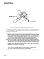
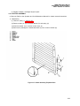
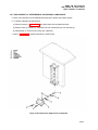
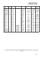
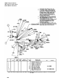
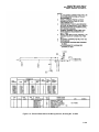
ARMY TM 9-6115-464-34
AIR FORCE 35C2-3-445-2
NAVY NAVFAC P-8-624-34
(7) If necessary, regrind crankshaft bearing journals to accept undersized bearings in accordance with
Table 3–3.
(8) inspect crankshaft gear for cracks and chipped, broken or excessive worn teeth.
(9) lf replacement of crankshaft gear is necessary, proceed as follows:
(a) Support crankshaft gear in arbor press and press crankshaft and woodruff key from gear.
(b) Heat replacement gear in an oven at 450°F. (232.2 °C.) for approximately one hour.
(c) Install woodruff key into crankshaft.
CAUTION
Wear heavy heat resistive asbestos gloves to avoid serious burns when handling
heated gear. Failure to observe this caution could result in equipment damage.
(d) Remove gear from oven and assemble onto crankshaft.
(e) Using a driver with an inside diameter of 2 inches, quickly drive gear into position,
(f) Allow crankshaft and gear to cool.
(10) Inspect connecting rod for cracks, breaks and excessively worn or damaged bushing.
(11) Check piston pin for nicks, burrs, cracks, and excessive wear.
(12) Remove minor nicks and burrs from piston by polishing with crocus cloth. Clean to remove abrasive
residue.
(13) If necessary, replace both piston pin and bushing.
NOTE
If new piston pin and bushing are used, check connecting rod alignment on a standard
aligning fixture.
(14) Inspect piston for deep scores and scratches and other damage.
(15) Insert each piston into its cylinder bore with a piece of 1/2 x 0.0050 feeler ribbon. A force of 5 to 8
pounds should be required to remove each ribbon. Replace all pistons if any are not within the
required limits.
NOTE
Cylinder bores may be rebored to accept oversized pistons (paragraph 3-55).
(16) Fit each piston ring into place into its cylinder bore and using a feeler gauge, measure gap
dimension. Gap shall be 0.0100 to 0.0200 inch. If gap is under 0.0100 inch, file as follows:
(a) Hold a file in a vise.
(b) Grasp piston ring in both hands.
(c) Insert file into ring gap and move ring down the entire length of the file. Be sure to apply equal
pressure on the ring.
(17) Roll each ring all the way around its piston groove to check clearance. If clearance is insufficient, lap
the sides of the ring on a piece of No. 000 grit emery cloth laid on a flat surface.
3-124