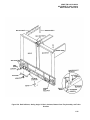
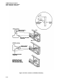
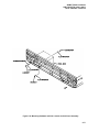
1
ARMY TM 9-6115-464-34
AIR FORCE 35C2-3-445-2
NAVY NAVFAC P-8-624-34
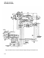
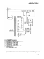
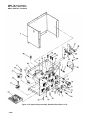
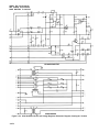
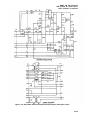
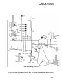
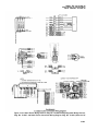
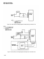
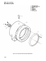
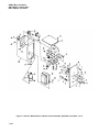
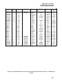
3-92. STATIC EXCITER AND VOLTAGE REGULATOR ASSEMBLY.
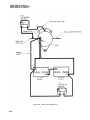
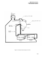
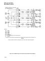
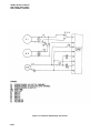
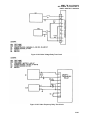
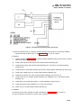
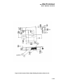
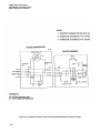
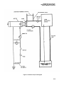
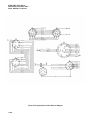
a. General. The static exciter and voltage regulator assembly provide excitation and voltage regulation for
the generator output voltage and compares it to a reference voltage which is established by the voltage adjust
rheostat on the generator set control cubicle. If difference exists, an error signal is sent to the static exciter.
Excitation current supplied by the current transformer assembly is altered by the error signal until generator
output voltage equals the reference voltage.
WARNING
Do not attempt to perform maintenance on the static exciter and voltage regulator
assembly while the generator set is operating. Severe electrical shock or death may
result from failure to observe this warning.
b. Removal.
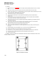
(1) Disconnect electrical connectors to static exciter and voltage regulator assembly.
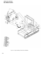
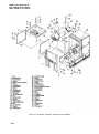
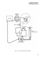
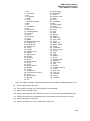
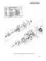
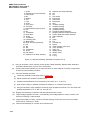
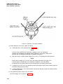
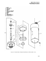
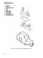
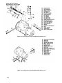
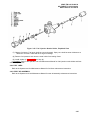
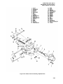
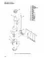
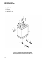
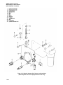
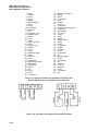
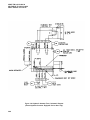
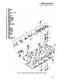
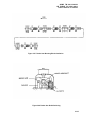
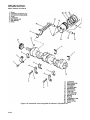
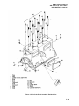
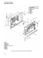
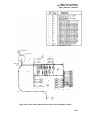
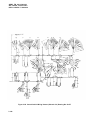
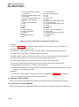
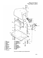
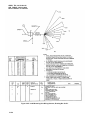
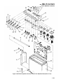
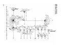
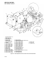
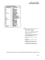
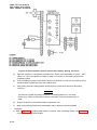
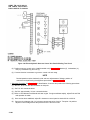
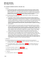
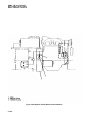
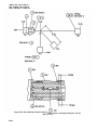
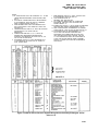
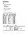
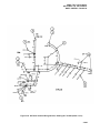
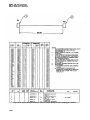
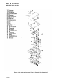
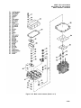
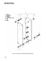
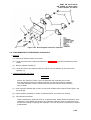
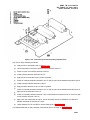
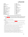
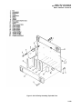
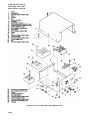
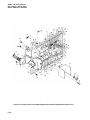
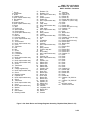
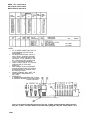
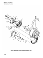
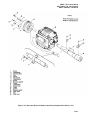
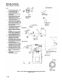
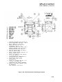
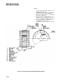
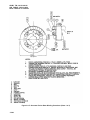
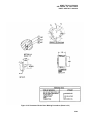
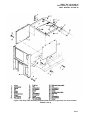
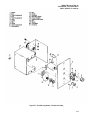
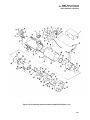
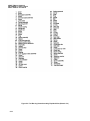
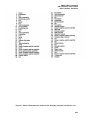
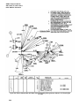
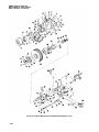
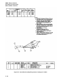
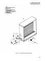
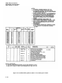
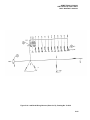
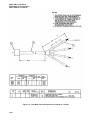
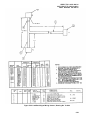
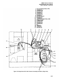
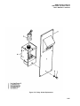
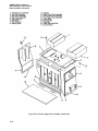
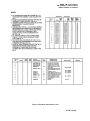
(2) Remove screws (1, figure 3-130) and Iockwasher (2) to remove static exciter and voltage regulator
assembly from generator set.
NOTE
Disassemble static exciter and voltage regulator assembly only as required to clean,
inspect, test and replace components.
c. Disassemblv. .
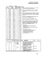
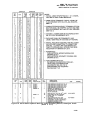
(1)
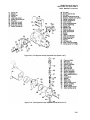
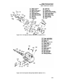
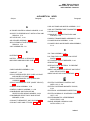
Remove screw (3, figure 3-130), on chassis cover (4) from chassis (68).
(2)
Remove nut and captive washer assembly (5), flat washer (6), screw (7) to remove heat sink
assembly (8).
(3)
Remove nut and captive washer assembly (9) and screw (10).
(4)
Remove wire (11), terminal lug (12), and semiconductor (13) as one assembly. Remove
semiconductor (14).
(5)
Remove nut and captive washer assembly (15), screws (16), heat sink (17) and heat sink support
(18).
(6)
Remove nut and captive washer assembly (19), screw (20), and terminal board (21).
(7)
Remove nut and captive washer assembly (22), screw (23), and transformer (24).
(8)
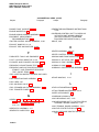
Remove nuts (25 and 26), screw (27), capacitor (28), Iockwasher (29) and bracket (30).
(9)
Remove nut & captive washer assembly (31), terminal (32), and nut& captive washer assembly (33).
(10) Remove nut & captive washer assembly (34), screw (35), and transformer (36).
(11)
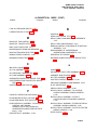
Remove screw (37), and voltage regulator assembly (38) from chassis (68).
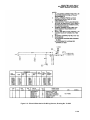
(12) Remove nut & captive washer assembly (39), screw (40), mounting bracket (41) and capacitor C2
(42).
(13) Remove nut & captive washer assembly (43), screw (44) and transformer (45).
(14) Remove nut & captive washer assembly (46), screw (47), nut& captive washer assembly (48),
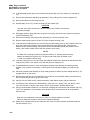
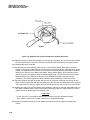
Washer (49), screw (50), mica washer (51), mounting bracket (52), resistors R1 and R2 (53 and 54).
3-264