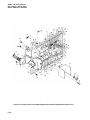
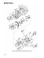
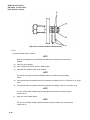
1
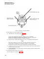
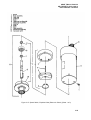
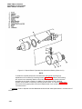
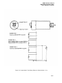
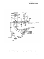
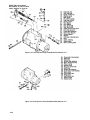
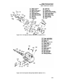
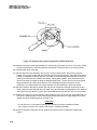
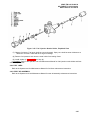
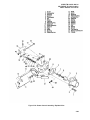
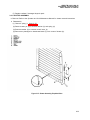
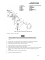
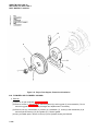
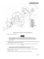
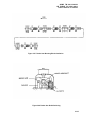
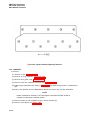
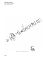
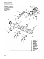
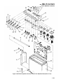
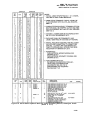
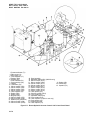
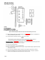
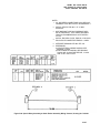
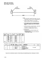
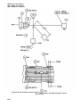
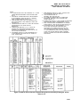
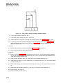
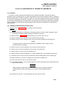
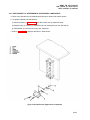
ARMY TM 9-6115-464-34
AIR FORCE TO 35C2-3-445-2
NAVY NAVFAC P-8-624-34
(26) Lift off the cam ring (121 ). Check and record the roller-to-roller dimension as instructed in the
assembly procedures. This dimension should be 1.9640 ± 0.0005 inches. Remove rollers (125),
shoes (126), plungers (127), and leaf springs (124). Discard spring screws (123).
CAUTION
Do not handle rotor shank. Failure to observe this caution could result in equipment
damage.
(27) Remove governor weight retainer snap ring (118) with snap ring pliers.
(28) The flexible retaining ring (120) should be replaced whenever the pump is disassembled. Insert the
snap ring plier, in the closed position, under the edge of the retaining ring between only two of the
rivets. Spread the pliers while applying pressure in an upward direction. A slight twisting motion will
snap the ring off the rivet. Repeat the process until the retaining ring is free from all rivets. Discard
the retaining ring.
d. Cleaning. Inspection. and Repair.
(1)
Inspect all springs, bores, grooves, and seal seats for wear, breakage, or damage. Repair or replace
as necessary.
(2)
Carefully inspect transfer pump blades for chipping on any edges, pitting, imbedded foreign particles,
or wear on the rounded ends. Visually check flat surfaces for scores. Determine blade wear by
measuring the length (0.538 inches minimum).
CAUTION
Do not handle the rotor shank. Do not force the plungers into their bore. Failure to
observe this caution could result in equipment damage.
(3)
While holding the rotor under fuel, insert the plungers into their bore. With thumb and forefinger over
the guide slots, tilt the rotor from side to side several times to insure complete freedom of movement
of the plungers. Interchanging or reversing their individual positions may be necessary, as these are
mated parts. Replace defective parts. If plungers are not visibly damaged, clean them with a soft
brush and a lacquer removing solvent such as lacquer thinner or acetone.
(4)
Examine the radii of the rotor which is contacted by the leaf springs, and the weight retainer for wear.
Check all slots, charging and discharge parts of the hydraulic head for chipping or erosion of edges.
Check the rotor shank for scratches.
NOTE
The rotor and hydraulic head are matched parts and shall be replaced as a unit.
(5)
Check the vent wire in the hydraulic head air bleed passage for freedom of movement. If the wire is
free, flush the head and blow out all passages with clean, dry compressed air. If the wire is stuck,
replace it after thoroughly cleaning the passages.
(6)
Check each cam roller for freedom of rotation in its shoe. Check each shoe for chipping or wear on
the surface contacted by the leaf spring.
(7)
Check the leaf springs for cracks, nicks, chipping, or distortion. Check for damage and wear along
rotor radii contact points and steps which retain roller shoes.
(8)
Examine the retainer sockets of governor weight retainer and the pivot point of each governor weight
for evidence of wear or damage. Replace the flexible snap ring (120) of the weight retainer.
(9)
Inspect the pivot points of the governor arm (86) pivot shaft for wear. Check the governor arm tabs at
the point which contacts the thrust sleeve. If either tab is worn flat, replace the governor arm.
3-55