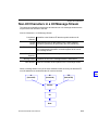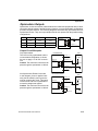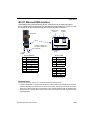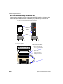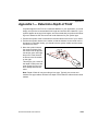
1
Quadrus EZ Reader
User's Manual
P/N 83-006700 Rev T
Copyright and Disclaimer
Copyright © 2007
by Microscan Systems, Inc.,
1201 S.W. 7th Street, Renton, Washington, U.S.A. 98057
(425) 226-5700 FAX: (425) 226-8682
ISO 9001:2000 Certification No. 06-1080
Issued by TüV USA
All rights reserved. The information contained herein is proprietary and is provided solely for the purpose
of allowing customers to operate and/or service Microscan manufactured equipment and is not to be
released, reproduced, or used for any other purpose without written permission of Microscan.
Throughout this manual, trademarked names might be used. Rather than put a trademark (™) symbol in
every occurrence of a trademarked name, we state herein that we are using the names only in an editorial
fashion, and to the benefit of the trademark owner, with no intention of infringement.
Disclaimer
The information and specifications described in this manual are subject to change without notice.
Latest Manual Version
For the latest version of this manual, see the Download page on our web site at www.microscan.com.
For technical support email [email protected].
Microscan Systems, Inc.
1201 S.W. 7th Street
Renton, Washington 98057
U.S.A.
Tel: 425 226 5700
Fax: 425 226 8250
[email protected]
Microscan Europe
Tel: 31 172 423360
Fax: 31 172 423366
Microscan Asia Pacific R.O.
Tel: 65 6846 1214
Fax: 65 6846 4641
ii
Quadrus EZ Reader User’s Manual
Introduction
Microscan Limited Warranty Statement and Exclusions
What Is Covered?
Microscan Systems Inc. warrants to the original purchaser that products manufactured by it will be free
from defects in material and workmanship under normal use and service for a period of one year from the
date of shipment. This warranty is specifically limited to, at Microscan’s sole option, repair or replacement
with a functionally equivalent unit and return without charge for service or return freight.
What Is Excluded?
This limited warranty specifically excludes the following: (1) Any products or parts that have been subject
to misuse, neglect, accident, unauthorized repair, improper installation, or abnormal conditions or operations; (2) Any products or parts that have been transferred by the original purchaser; (3) Customer misadjustment of settings contrary to the procedure described in the Microscan Systems Inc. owners manual;
(4) Upgrading software versions at customer request unless required to meet specifications in effect at the
time of purchase; (5) Units returned and found to have no failure will be excluded; (6) Claims for damage
in transit are to be directed to the freight carrier upon receipt. Any use of the product is at purchaser’s own
risk. This limited warranty is the only warranty provided by Microscan Systems Inc. regarding the product.
Except for the limited warranty above, the product is provided “as is.” To the maximum extent permitted by
law, this express warranty excludes all other warranties, express or implied, including but not limited to,
implied warranties of merchantability and. Technical support questions may be directed to: [email protected] Register your product with Microscan: www.microscan.com/register fitness for a
particular purpose. Microscan Systems Inc. does not warrant that the functions contained in the product
will meet any requirements or needs purchaser may have, or that the product will operate error free, or in
an uninterrupted fashion, or that any defects or errors in the product will be corrected, or that the product
is compatible with any particular machinery.
Limitation of Liability
In no event shall Microscan Systems Inc. be liable to you or any third party for any special, incidental, or
consequential damages (including, without limitation, indirect, special, punitive, or exemplary damages for
loss of business, loss of profits, business interruption, or loss of business information), whether in contract,
tort, or otherwise, even if Microscan Systems Inc. has been advised of the possibility of such damages.
Microscan Systems Inc.’s aggregate liability with respect to its obligations under this warranty or otherwise
with respect to the product and documentation or otherwise shall not exceed the amount paid by you for
the product and documentation. Some jurisdictions do not allow the exclusion or limitation of incidental or
consequential damages or limitations on an implied warranty, so the above limitation or exclusion may not
apply to you. This warranty gives you specific legal rights, and you may also have other rights which may
vary from state to state.
Tel: 425.226.5700 | Fax: 425.226.8250 | [email protected]
Quadrus EZ Reader User’s Manual
iii
Table of Contents
Table of Contents
Chapter 1
Quick Start
Step 1 Check Required Hardware........................................................... 1-2
Step 2 Connect the System..................................................................... 1-3
Step 3 Position Reader and Symbol ....................................................... 1-4
Step 4 Install ESP ................................................................................... 1-5
Step 5 Select Model ................................................................................ 1-6
Step 6 Select Communications Protocol ................................................. 1-7
Step 7 Locate the Symbol in the FOV ..................................................... 1-8
Step 8 Calibrate Settings....................................................................... 1-10
Step 9 Perform Readability Test ........................................................... 1-11
Step 10 Applications.............................................................................. 1-12
Step 11 Make Menu Changes and Save in ESP................................... 1-13
Video Output Option .............................................................................. 1-14
Chapter 2
Using ESP
EZ Mode .................................................................................................. 2-2
Application Mode ..................................................................................... 2-3
Menu Toolbar .......................................................................................... 2-4
Connecting ............................................................................................ 2-11
View....................................................................................................... 2-12
Navigating in ESP ................................................................................. 2-13
Send/Receive Options........................................................................... 2-14
Chapter 3
Communications
Communications by ESP......................................................................... 2-2
Communications Serial Commands ........................................................ 2-3
RS-232/422 Host Port ............................................................................. 2-4
RS-232 Auxiliary Port ............................................................................ 2-11
Network ................................................................................................. 2-21
Preamble ............................................................................................... 2-24
Postamble ............................................................................................. 2-25
Response Timeout ................................................................................ 2-26
LRC Status ............................................................................................ 2-27
Aux Port System Data Status ................................................................ 2-28
Chapter 4
Read Cycle
Read Cycle by ESP ................................................................................. 3-2
Read Cycle Serial Commands ................................................................ 3-3
Read Cycle Setup ................................................................................... 3-4
Multisymbol ............................................................................................. 3-5
Trigger ..................................................................................................... 3-7
Serial Trigger ......................................................................................... 3-13
End of Read Cycle ................................................................................ 3-15
Active Camera ....................................................................................... 3-17
Capture Mode........................................................................................ 3-18
iv
Quadrus EZ Reader User’s Manual
Introduction
Capture Timing ...................................................................................... 3-23
Dual Camera Switching ......................................................................... 3-25
Store Noread Image .............................................................................. 3-30
Chapter 5
Symbologies
Symbologies by ESP ............................................................................... 4-2
Symbologies Serial Commands .............................................................. 4-3
Data Matrix .............................................................................................. 4-4
QR Code.................................................................................................. 4-7
Code 39 ................................................................................................... 4-8
Code 128 ............................................................................................... 4-11
BC412.................................................................................................... 4-12
Interleaved 2 of 5 ................................................................................... 4-14
UPC/EAN............................................................................................... 4-17
Pharmacode .......................................................................................... 4-20
RSS Expanded ...................................................................................... 4-22
RSS Limited........................................................................................... 4-23
RSS-14 .................................................................................................. 4-24
PDF417 ................................................................................................. 4-25
MicroPDF417......................................................................................... 4-27
Composite ............................................................................................. 4-28
Narrow Margins ..................................................................................... 4-39
Symbology ID ........................................................................................ 4-30
Background Color .................................................................................. 4-31
Chapter 6
I/0 Parameters
I/O Parameters by ESP .......................................................................... 5-2
I/O Parameters Serial Commands........................................................... 5-3
Symbol Data Output ................................................................................ 5-4
When to Output Symbol Data .................................................................. 5-6
Noread Message ..................................................................................... 5-7
Bad/No Symbol Qualification ................................................................. 5-10
Read Duration Output............................................................................ 5-18
Output Indicators ................................................................................... 5-19
Serial Verification................................................................................... 5-23
Video Output.......................................................................................... 5-25
Image Output ......................................................................................... 5-28
Image Captioning .................................................................................. 5-30
Synchronous Trigger ............................................................................. 5-32
EZ Button............................................................................................... 5-34
Input 1.................................................................................................... 5-38
Output 1 Parameters ............................................................................. 5-39
Output 2 Parameters ............................................................................. 5-52
Output 3 Parameters ............................................................................. 5-54
Chapter 7
Symbol Quality
Symbol Quality by ESP ........................................................................... 6-2
Quadrus EZ Reader User’s Manual
v
Table of Contents
Symbol Quality Serial Commands........................................................... 6-2
Overview of Symbol Quality .................................................................... 6-3
Global ...................................................................................................... 6-4
Data Matrix .............................................................................................. 6-5
Static Symbol Quality Outputs............................................................... 6-13
Chapter 8
Matchcode
Matchcode by ESP .................................................................................. 7-2
Matchcode Serial Commands ................................................................. 7-2
Overview of Matchcode ........................................................................... 7-3
Matchcode Type ...................................................................................... 7-4
Sequential Matching ................................................................................ 7-5
Match Start Position ................................................................................ 7-6
Match Length........................................................................................... 7-7
Wild Card Character ................................................................................ 7-8
Sequence On Noread.............................................................................. 7-9
Sequence On Mismatch ........................................................................ 7-10
Sequence Step ..................................................................................... 7-11
Match Replace ...................................................................................... 7-12
Mismatch Replace ................................................................................. 7-13
New Master Pin ..................................................................................... 7-14
Chapter 9
Diagnostics
Diagnostics by ESP ................................................................................. 8-2
Diagnostics Serial Commands ................................................................ 8-2
Counts (Read Only)................................................................................. 8-3
External Camera Message ...................................................................... 8-4
Over Temperature Message ................................................................... 8-6
Service Message ..................................................................................... 8-7
Chapter 10
Camera Setup
Camera Setup by ESP ............................................................................ 9-2
Camera Setup Serial Commands............................................................ 9-2
Video ....................................................................................................... 9-3
Evaluation................................................................................................ 9-5
Region of Interest (ROI) .......................................................................... 9-8
Dynamic Setup ...................................................................................... 9-12
CCD Image Sensor ............................................................................... 9-14
CMOS Image Sensor ............................................................................ 9-15
Illumination Source ................................................................................ 9-17
Thresholding.......................................................................................... 9-18
Image Processing Settings.................................................................... 9-19
Hollow Mode.......................................................................................... 9-21
Mirrored Image ...................................................................................... 9-22
Other Camera Parameters .................................................................... 9-23
Chapter 11
IP Database
IP Database by ESP.............................................................................. 10-2
vi
Quadrus EZ Reader User’s Manual
Introduction
IP Database Serial Commands ............................................................. 10-3
Overview of IP Database ....................................................................... 10-4
Operation of IP Database ...................................................................... 10-4
IP Database Window ............................................................................. 10-6
Number of Active Database Settings..................................................... 10-7
CCD Image Sensor Database ............................................................... 10-8
CMOS Image Sensor .......................................................................... 10-10
Save Current Settings to Database ..................................................... 10-13
Load Current Settings from Database ................................................. 10-13
Request Database Settings ................................................................. 10-14
Request All Database Settings............................................................ 10-14
Chapter 12
Terminal
Terminal Window ................................................................................... 11-2
Find Function ......................................................................................... 11-3
Macros................................................................................................... 11-4
Terminal Window Menus ....................................................................... 11-5
Chapter 13
Utilities
Utilities Serial Commands ..................................................................... 12-2
Read Rate ............................................................................................. 12-3
Counters ................................................................................................ 12-4
Device Control ....................................................................................... 12-6
Master Database ................................................................................... 12-7
Firmware.............................................................................................. 12-12
Bar Code Configuration. ...................................................................... 12-16
Defaulting/Saving/Resetting ................................................................ 12-17
Reader Status Requests ..................................................................... 12-19
Other Operational Serial Commands .................................................. 12-20
Chapter 14
Unique Item Identifiers
UII Overview .......................................................................................... 13-2
Non-UII Characters in a UII Message Stream ....................................... 13-3
UII Mode Features ................................................................................. 13-4
Error Messaging .................................................................................... 13-6
Valid Formats ........................................................................................ 13-8
Chapter 15
Output Format
Output Format Serial Commands .......................................................... 14-2
Output Format Status ............................................................................ 14-3
Format Assign ....................................................................................... 14-4
Format Extract ....................................................................................... 14-5
Format Insert ......................................................................................... 14-7
Output Filter Configuration .................................................................... 14-9
Ordered Output Filter........................................................................... 14-13
Chapter 16
Ethernet
Step 1 Setup.......................................................................................... 15-2
Quadrus EZ Reader User’s Manual
vii
Table of Contents
Step 2 Preliminary Steps ....................................................................... 15-3
Step 3 Communicating in Ethernet........................................................ 15-7
Ethernet Application .............................................................................. 15-8
Appendices
Appendix A General Specifications .........................................................A-2
Appendix B Electrical Specifications .......................................................A-4
Appendix C Quadrus EZ DPM ................................................................A-8
Appendix D Quadrus EZ FLEX ...............................................................A-9
Appendix E Connectivity Accessories ...................................................A-10
Appendix F Serial Configuration Commands ........................................A-13
Appendix G ASCII Table .......................................................................A-20
Appendix H Data Matrix Symbology......................................................A-22
Appendix I Determine Depth of Field ....................................................A-23
Appendix J Field of View and Lenses ...................................................A-24
Appendix K Rapid Capture Mode ..........................................................A-28
Appendix L Object Detector ..................................................................A-30
Appendix M Operational Tips ................................................................A-31
Appendix N Embedded Menus..............................................................A-32
Appendix O Interface Standards ...........................................................A-33
Appendix P Multidrop Communications ................................................A-34
Appendix Q Glossary of Terms .............................................................A-37
viii
Quadrus EZ Reader User’s Manual
Introduction
About the Quadrus EZ Reader
The key features of the Quadrus EZ are:
• A multi-function EZ button for location, calibration, and reading
• “X” pattern symbol locator
• High speed image processing up to 60 reads per second
• Factory-adjustable focus 2 to 10 inches
• Ability to read both 2D and linear symbols
• Ability to read difficult symbols
• Secondary video input from RS-170 non-interlaced analog cameras
To aid in setup, the Quadrus EZ incorporates three primary features:
• An “X” locator identifies the center point of the FOV
• A calibration feature to optimize readability
• A green flash (visible from all angles) to signal a successful read
Host Communications
There are four ways to configure and test the Quadrus EZ:
1. EZ button.
2. Microscan’s Windows-based ESP (Easy Setup Program), which offers point-and-click
ease of use and visual responses to user adjustments.
3. Serial commands, such as <K100,1>, that can be sent from ESP’s Terminal window
or another terminal program.
4. The tree control menus and graphic interfaces in ESP’s App Mode.
Quadrus EZ Reader User’s Manual
ix
About the Quadrus EZ Reader User’s Manual
About the Quadrus EZ Reader User’s Manual
This manual provides complete information on setting up, installing, and configuring the
reader. The chapters are presented in the order in which a reader might be set up and
made ready for operation.
Highlighting
Serial commands, selections inside instructions, and menu defaults are highlighted in red
bold. Cross-references are highlighted in blue. Web links and outside references are
highlighted in blue bold italics. References to menu topics are highlighted in Bold Initial
Caps. References to topic headings within this manual or other documents are enclosed
in quotation marks.
x
Quadrus EZ Reader User’s Manual
Introduction
Warning and Caution Summary
WARNING
LED LIGHT
DO NOT VIEW DIRECTLY WITH OPTICAL INSTRUMENTS
CLASS 1M LED PRODUCT
Light Output: 648 cd. Wavelength: 464 nm; 518 nm; 635 nm.
IEC 60825-1:1993+A1:1997+A2:2001
• Viewing the Quadrus EZ’s LED output with optical instruments such as magnifiers, eye
loupes, or microscopes within a distance of 100 mm could cause serious eye injury.
• Maximum LED light output: 648 cd.
• Wavelength: 464 nm; 518 nm; 635 nm.
• Location of the Quadrus EZ’s LED aperture window:
LED Aperture Window
• CAUTION: Use of controls or adjustments or performance of procedures other than
those specified herein may result in hazardous radiation exposure.
Quadrus EZ Reader User’s Manual
xi
Statement of Agency Compliance
Statement of Agency Compliance
This equipment has been tested and found to comply with the limits for a Class A digital
device, pursuant to part 15 of the FCC Rules. These limits are designed to provide reasonable
protection against harmful interference in a residential installation. This equipment generates,
uses, and can radiate radio frequency energy, and, if not installed and used in accordance with
the instructions, may cause harmful interference to radio communications. However, there is
no guarantee that interference will not occur in a particular installation. If this equipment does
cause harmful interference to radio or television reception, which can be determined by turning
the equipment off and on, the user is encouraged to try to correct the interference by one or
more of the following measures:
• Reorient or relocate the receiving antenna
• Increase the separation between the equipment and receiver
• Connect the equipment into an outlet on a circuit different from that to which the receiver
is connected
• Consult the dealer or an experienced radio/TV technician for help
For connection to a UL-listed direct plug-in power unit marked Class II and rated 10 to 28
VDC at 10 watts (CCD) or 8 watts (CMOS), or greater if using electrical accessories.
European models must use a similarly rated Class I or Class II power supply that is certified
to comply with standard for safety IEC 60950.
Approvals
This equipment is in compliance or approved by the following organizations:
• CDRH (Center for Devices & Radiological Health)
• FCC (Federal Communications Commission)
• CE (Conformité Européenne)
• BSMI (Bureau of Standards, Metrology and Inspection)
xii
Quadrus EZ Reader User’s Manual
1 Quick Start
Contents
Step 1 Check Required Hardware................................................................................................ 1-2
Step 2 Connect the System.......................................................................................................... 1-3
Step 3 Position Reader and Symbol............................................................................................. 1-4
Step 4 Install ESP......................................................................................................................... 1-5
Step 5 Select Model ..................................................................................................................... 1-6
Step 6 Select Communications Protocol ...................................................................................... 1-7
Step 7 Locate the Symbol in the FOV .......................................................................................... 1-8
Step 8 Calibrate Settings........................................................................................................... 1-10
Step 9 Perform Readability Test................................................................................................ 1-11
Step 10 Applications.................................................................................................................. 1-12
Step 11 Make Menu Changes and Save in ESP....................................................................... 1-13
Video Output Option .................................................................................................................. 1-14
This chapter is designed to get your reader up and running quicklyusing the reader’s EZ
button or ESP (Easy Setup Program) so the user can get a sense of its capabilities and
test sample symbols.
Detailed setup information for installing the reader into the actual application can be
obtained in the subsequent chapters.
In addition to ESP, you can send commands to your reader by serial commands and
through the reader’s embedded menus.
Quadrus EZ Reader User’s Manual
1-1
Check Required Hardware
Step 1 — Check Required Hardware
To get started with just the EZ Button
You will need:
• A Quadrus EZ Reader (1), FIS 6700-XXXX.
• An IB-150 Kit, 98-000040-02, which includes a cable, 61-000034-02, and the IB-150
Interface Box (2), 99-000008-02.
• A Power Supply (3), 97-100004-15 (90-264 VAC, 24VDC).
If connecting to a host by RS-232
You will also need the following:
• A host computer with either a terminal
communications program or Microscan’s
ESP, which runs under Windows operating
system, Windows 98 or higher.
• An IB-150 Host Communications Cable (6),
61-000034-02 (25-pin socket to 9-pin socket).
• Object Detector (5) (optional), 99-000017-01.
1
4
7
2
HOST
READER
AUX PORT
6
If connecting to a host by TCP/IP
See Chapter 15, Ethernet.
3
5
Hardware Configuration
Caution: Be sure that all cables are connected BEFORE applying power to the
system. Always power down BEFORE disconnecting any cables.
1-2
Quadrus EZ Reader User’s Manual
Quick Start
Step 2 — Connect the System
You can connect the Quadrus EZ by EZ button, RS-232, or TCP-IP (Ethernet).
Connecting for EZ Button Setup without a Host
• Connect the Quadrus EZ Reader to the IB-150 Kit, 98-000040-02.
• Connect Power Supply.
• Apply power to the reader.
Connecting by RS-232
• Connect the reader to the IB-150 Kit,
98-000040-02.
• Connect the IB-150 Host Communications
Cable, 61-000034-02, to the host and the
host connector on the side of the IB-150
interface box.
Note: When wiring the interface box to a
host with a 25-pin host connector, cross
pins 2 and 3. When wiring the interface box
to a host with a 9-pin host connector, do
NOT cross pins 2 and 3.
1. Connect power supply.
1
25
Side View of IB-150 showing Host 25-pin
Socket Connection
2. Apply power to the reader.
Connecting to a Host by TCP/IP
See Chapter 15, Ethernet.
Quadrus EZ Reader User’s Manual
1-3
Position Reader and Symbol
Step 3 — Position Reader and Symbol
• Position the reader at the focal distance recommended on the back of the reader, for
example FD = 4”.
• Tip the reader relative to the symbol to avoid the glare of direct (specular) reflection. The
case parting line should be perpendicular to the plane of the symbol by either pitching
the symbol or the reader as shown.
• Position the reader in a place devoid of sunlight.
• Symbols can be rotated (tilted) in any angle; however, for best results symbols should
be aligned with the FOV (field of view).
Parting Line
Stand
Focal distance
90°
Reader Position
• In the case of linear symbols, aligning the bars in the direction of their movement (“ladder”
orientation) will minimize the chances of blurring and produce better reads.
• Avoid excessive skew or pitch. Maximum skew is ±30°; maximum pitch is ±30°.
Note: For instant setup and validation, the Quadrus EZ can be hand-held or laid on its
side; but for accuracy a mounting stand such as the one shown above is recommended.
1-4
Quadrus EZ Reader User’s Manual
Quick Start
Step 4 — Install ESP
ESP stands for Easy Setup Program.
ESP provides a quick and easy way to set up and configure your reader.
If installing from a Microscan Installation and Support CD:
1. Insert your Microscan Installation and Support CD in your computer’s CD drive.
2. Choose ESP Software from the main menu.
3. Launch Setup.exe under ESP and follow the prompts.
If downloading from the web:
1. Go to http://www.microscan.com/downloadcenter
2. Create a new “myMicroscan” member account or, if you are already a member, enter
your user name and password.
3. Click the Download Software link and extract the latest version of ESP to a directory
location of your choice. Note where your ESP.exe file is stored on your hard drive.
4. At the end of the installation process, the following icon will appear on your desktop:
5. Click the ESP icon to start the program.
Quadrus EZ Reader User’s Manual
1-5
Select Model
Step 5 — Select Model
When you start the program, the following menu will appear:
Note: If you need to select another model later, click the Switch Model button.
1. Click the Quadrus EZ button and then click OK. If you do not want to make this
selection every time you start ESP, uncheck “Show this window at Startup”.
2. Select the default reader name (Quadrus EZ-1), or type a name of your choice in
the Description text field and click OK.
3. Click Yes when this dialog appears:
1-6
Quadrus EZ Reader User’s Manual
Quick Start
Step 6 — Select Communications Protocol
When the Select Protocol dialog appears, choose
either RS-232 or TCP/IP (Ethernet) and click Next.
RS-232
1. In the RS-232 dialog, if your communications port
is not the default COM1, use the dropdown menu
to change your communications port.
2. Click Connect.
3. When connected, the CONNECTED message will
appear in a green box in the status bar on the bottom right of the dialog.
4. If the connection fails, click the Autoconnect button, select a different Com port,
and try again.
Note: If your host settings cannot be changed to match the reader’s settings, check the
Force Connect box.
TCP/IP (Ethernet)
Both ESP and the reader will need to have TCP/IP
addresses assigned.
1. If no address has been assigned to the reader, go
to Chapter 15, Ethernet. If your reader has already
been assigned IP addresses, enter the IP address
in the dialog box.
2. Click Connect.
Tip: If you do not see either the CONNECTED or DISCONNECTED messages at the bottom
of your dialog, try expanding the ESP window horizontally.
Quadrus EZ Reader User’s Manual
1-7
Locate the Symbol in the FOV
Step 7 — Locate the Symbol in the FOV
In this step, you move the symbol or the
reader so that the “X” pattern is centered
over the symbol.
It is important that the whole symbol falls
within the field of view (FOV) of the reader.
(The FOV is what appears in the Locate/
Calibrate window.)
Note: Holding the EZ button until you hear
4 beeps enables Live video output (if
attached to a monitor).
Locate by EZ Button
When not connected to a computer, the EZ
setup button will allow you to quickly locate a
symbol in the reader’s FOV.
1. Hold down the EZ setup button for about
one second and release when you hear one
short beep. You will see the blue X-pattern.
EZ Button
2. Center the X-pattern on the symbol.
Note: To end all EZ button functions, press the EZ button and quickly release.
1-8
Quadrus EZ Reader User’s Manual
Quick Start
Locate by ESP
1. In the EZ menu, click the Locate button to enable the X-pattern.
2. You will see the X-pattern in front of the reader.
3. Center the X-pattern over the symbol you want to read.
4. Click the Stop button to end the locate mode.
Quadrus EZ Reader User’s Manual
1-9
Calibrate Settings
Step 8 — Calibrate Settings
Quadrus EZ image settings can be
adjusted automatically for optimum readability by either the EZ setup button or ESP.
During the calibration routine, the reader
will flash its LEDs while searching through
various IP (image processing) settings and
matching them with the highest read rates.
Upon successful completion of this routine,
a green LED pattern will flash brightly and
illuminate the symbol. If unsuccessful, the
reader will emit 5 short beeps and stop
searching.
Calibrate by EZ Button
1. Hold down the EZ setup button about
2 seconds and release when you hear two short beeps.
2. The reader will search through various IP settings and match them with the highest
read rates.
Note: To end all EZ button functions, press the EZ button and quickly release.
Calibrate by ESP
1. Click the Calibrate button.
2. The reader will search through various IP settings and match
them with the highest read rates.
A successful calibration will display a green frame around the
symbol. Following this, a message, “Uploading all reader parameters” will appear.
After a moment the symbol’s data and related features will be presented under the
“Symbol Information” box below the image display window.
Calibrate by Serial Command
Send <op,6,1> to begin calibration. Send <op,6,0> to end calibration.
1-10
Quadrus EZ Reader User’s Manual
Quick Start
Step 9 — Perform Readability Test
This test will let you know the percent of good reads per captures achieved by the reader.
Testing by EZ Button
1. To start the read rate
test, hold down the EZ
setup button about 3
seconds until you hear
three short beeps and
see the alternating IP
and finder pattern LEDs.
20%, 40%, 60%, 80%, 100% these LEDs are only active while
the reader is in a read rate test
and represent the percentage of
good reads per images captured.
While the symbol is
being decoded, the read
rate LEDs will indicate
the corresponding read
rate percentage on the
side of the unit.
2. To end the read rate test,
press the EZ button and
quickly release.
Good Read Percentage
Testing by ESP
1. Click the Test button to
start the read rate test
and Stop to end it.
If your symbol has been
successfully decoded, its
data and related features
will be presented under
“Symbol Information.”
Also, while the symbol is
being decoded, the read rate LEDs will indicate the corresponding read rate percentage
on the side of the unit as shown above.
2. To end the test, click the Stop button.
Testing by Serial Command
You can also start a test with the <C> or <Cp> command and end it with the <J> command.
Quadrus EZ Reader User’s Manual
1-11
Applications
Step 10 — Applications
To make setup changes to the Quadrus EZ, click the App Mode button.
From here you can make changes in the configuration files that appear on the second row
of icons.
You can also do the following:
• Send or Receive commands by clicking the Send/Recv button.
• Make changes to Camera options by clicking the Camera button.
• Access the Terminal window to see data or entering serial commands by clicking the
Terminal button.
• Review status settings or make changes to operational commands by clicking the Utilities
button.
• Format data for output by clicking the Output Format button.
For details, see ESP Help in the pulldown menu.
The window on the left represents the tree control. The window on the right is where image
captures are displayed.
1-12
Quadrus EZ Reader User’s Manual
Quick Start
Step 11 — Make Menu Changes and Save in ESP
To make changes to a configuration setting:
1. Left click on the + to expand
tree.
2. Double click on parameter
and click once in selection
box to view options.
3. Place your cursor in the
selection box, scroll down to
the setting you want to
change and click once on
the setting.
4. Left click again on the open
screen to complete the
selection.
5. Right click on the open screen and
select Save to Scanner to implement the
command in the reader.
You have 3 choices for saving:
• Send, No Save. Changes will be lost when power is recycled.
Caution: This only saves certain commands to memory.
• All other commands are saved for power-on, the same as the Send and Save option.
• Send and Save. This activates all changes in current memory and saves to the scanner
for power-on.
• Send and Save as Customer Settings. Same as above, except that these settings are
saved to a special section of NOVRAM.
Note: This option must be enabled under the Options pull down menu before it will be
available as a save option.
Quadrus EZ Reader User’s Manual
1-13
Make Menu Changes and Save in ESP
Video Output Option
You can connect a remote video monitor (RS-170/monochrome, non-interlaced) via the
video output port on the back of the Quadrus EZ Reader and view live video or triggered
events such as a good read, no read, or slide show of on-going captures.
To Enable Live Video:
Press and hold the EZ button until you hear a series of 4 beeps.
Video
Output
Video
Input
Note for CCD readers: When Live video mode is active, in order to synchronize with the
video format, a shutter time of 1/1000 is the lowest shutter speed setting that can be
applied to the camera settings. Slower shutter speeds will disable the video output.
When connected to a remote video with Live video mode active, the monitor screen is a
close representation of the FOV. This allows you to visually verify that a symbol is within
the FOV and the X-pattern is centered over it.
Note: During normal read cycle operations, the X-pattern will not be present unless
enabled by <K750,,1> or by ESP.
Video Input Option
You can connect an external camera (RS-170/monochrome non-interlaced, progressive
format, 512 lines, 30 fps) for streaming captures into the Quadrus EZ Reader.
Note: Power to an external camera is not supplied by the Quadrus EZ Reader.
1-14
Quadrus EZ Reader User’s Manual
2 Communications
Contents
Communications by ESP .............................................................................................................. 2-2
Communications Serial Commands.............................................................................................. 2-3
RS-232/422 Host Port................................................................................................................... 2-4
RS-232 Auxiliary Port................................................................................................................. 2-11
Network...................................................................................................................................... 2-21
Preamble.................................................................................................................................... 2-24
Postamble .................................................................................................................................. 2-25
Response Timeout..................................................................................................................... 2-26
LRC Status................................................................................................................................. 2-27
Aux Port System Data Status .................................................................................................... 2-28
This section tells how to set up communications parameters with the host and an auxiliary
terminal.
With Microscan’s ESP (Easy Setup Program), configuration changes can be made in the
ESP menus, then sent and saved to your reader. The user can also send serial commands
to the reader via the ESP’s Terminal window.
Note: The characters NULL <> and , can only be entered through embedded menus, not
through ESP or serial commands.
Quadrus EZ Reader User’s Manual
2-1
Communications by ESP
Communications by ESP
Click this button to bring up
the Applications menu.
Click this button to bring up the
Communications parameters.
To open nested options,
single-click the +.
To change a setting,
double-click the setting
and use your cursor to
scroll through the
options.
2-2
Quadrus EZ Reader User’s Manual
Communications
Communications Serial Commands
Host Port Connections
Host Port Protocol
Host 232/422 Status
Auxiliary Port
Daisy Chain Autoconfigure
Daisy Chain ID
Ethernet Configuration
Preamble
Postamble
Response Timeout
LRC
Aux Port System Data Status
Quadrus EZ Reader User’s Manual
<K100,baud rate,parity,stop bits,data bits>
<K140,protocol>
<K102,host 422>
<K101,aux port mode,baud rate,parity,stop bits,data
bits,daisy chain ID status,daisy chain ID>
<K150DAISY>
<K151,daisy chain reader #,daisy chain reader ID>
<K125,IP address,subnet address,gatewayaddress,IP
address mode,primary TCP port,video TCP port>
<K141,status,preamble characters>
<K142,status,postamble characters>
<K143,response timeout>
<K145,status>
<K146,aux port system data>
2-3
RS-232/422 Host Port
RS-232/422 Host Port
The host port can be configured with RS-232 and RS-422 connections.
Host Port Connections
These settings define the basic transmission speeds and digital standards that ensure
common formatting.
Baud Rate, Host Port
Usage:
Can be used to transfer data faster or to match host port settings.
Definition:
The rate at which the reader and host transfer data back and forth.
Serial Cmd:
<K100,baud rate,parity,stop bits,data bits>
Default:
115.2K
Options:
0 = 600
3 = 4800
6 = 38.4K
1 = 1200
4 = 9600
7 = 57.6K
2 = 2400
5 = 19.2K
8 = 115.2K
Parity, Host Port
Usage:
Only changed if necessary to match host setting.
Definition:
An error detection routine in which one data bit in each character is set to 1
or 0 so that the total number of 1 bits in the data field is even or odd.
Serial Cmd:
<K100,baud rate,parity,stop bits,data bits>
Default:
None
Options:
0 = None
1 = Even
2 = Odd
Stop Bits, Host Port
Usage:
Only changed if necessary to match host setting.
Definition:
One or two bits added to the end of each character to indicate the end of
the character.
Serial Cmd:
<K100,baud rate,parity,stop bits,data bits>
Default:
One
Options:
0 = One
2-4
1 = Two
Quadrus EZ Reader User’s Manual
Communications
Data Bits, Host Port
Usage:
Only changed if necessary to match host setting.
Definition:
One or two bits added to the end of each character to indicate the end of
the character.
Serial Cmd:
<K100,baud rate,parity,stop bits,data bits>
Default:
8
Options:
0 = Seven
Quadrus EZ Reader User’s Manual
1 = Eight
2-5
RS-232/422 Host Port
Host Port Protocol
Usage:
In general, the point-to-point protocols will work well in most applications.
They require no address and must use RS-232 or RS-422 communications
standards.
Definition:
Protocols define the sequence and format in which information is transferred between the reader and the host, or in the case of Multidrop,
between readers and a concentrator.
Serial Cmd:
<K140,protocol>
Default:
Point-to-Point
Options:
0 = Point-to-Point
1 = Point-to-Point with RTS/CTS
2 = Point-to-Point with XON/XOFF
3 = Point-to-Point with RTS/CTS & XON/XOFF
4 = Polling Mode D
6 = User Defined
Point-to-Point (standard)
Usage:
Used only with RS-232 or RS-422.
Definition:
Standard Point-to-Point requires no address and sends data to the host
whenever it is available, without a request or handshake from the host.
Serial Cmd:
<K140,0>
Point-to-Point with XON/XOFF
Usage:
If an XOFF has been received from the host, data will not be sent to the
host until the host sends an XON. During the XOFF phase, the host is free
to carry on other chores and accept data from other devices.
Used only with RS-232.
Definition:
This option enables the host to send the XON and XOFF command as a
single byte transmission command of start (^Q) or stop (^S).
Serial Cmd:
<K140,1>
2-6
Quadrus EZ Reader User’s Manual
Communications
Point-to-Point with RTS/CTS
Usage:
A reader initiates a data transfer with an RTS (request-to-send) transmission. The host, when ready, responds with a CTS (clear-to-send) and the
data is transmitted. CTS and RTS signals are transmitted over two dedicated wires as defined in the RS-232 standard.
Used only with RS-232.
Definition:
Point-to-Point with RTS/CTS (request-to-send/clear-to-send) is a simple
hardware handshaking protocol that allows a reader to initiate data transfers to the host.
Serial Cmd:
<K140,2>
Point-to-Point with RTS/CTS & XON/XOFF
Usage:
Used only with RS-232.
Definition:
This option is a combination of Point-to-Point with RTS/CTS and Pointto-Point with XON/XOFF.
Serial Cmd:
<K140,3>
Polling Mode D
Usage:
When in Polling Mode D, an address of 1 is automatically displayed on the
configuration menu. However, during transmission, a 1C hex poll address
(FS) and a 1D hex select address (GS) are substituted for the 1.
Definition:
Like Point-to-Point, Polling Mode D requires a dedicated connection to
the host; but unlike Point-to-Point, it requires an address and must wait for
a poll from the host before sending data.
Serial Cmd:
<K140,4>
User Defined Point-to-Point
Usage:
Useful for developing custom protocols in polled or unpolled mode.
Definition:
Allows the user to customize the point-to-point protocol.
Serial Cmd:
<K140,6,RES,address,REQ,EOT,STX,ETX,ACK,NAK,from host>
User Defined Address
Definition:
User Defined is considered to be in a polled mode only if an address has
been assigned.
Serial Cmd:
<K140,6RES,address,REQ,EOT,STX,ETX,ACK,NAK,from host>
Default:
No address
Options:
Any ASCII character except a NULL < , or >.
Quadrus EZ Reader User’s Manual
2-7
RS-232/422 Host Port
User Defined Example
Definition:
Example: ACK/NAK protocol can be configured using User Defined. The
reader will transmit data to the host, when an ACK is received, it will carry on
with its business. If a NAK or response timeout occurs, the reader will resend the data to the host up to 3 more times before aborting.
Tip: To use User Defined Point-to-Point, first select Point-to-Point
<K140,0> and then User Defined <K140,6>.
Example: To select an unpolled ACK/NAK User Defined protocol with LRC
disabled, send <K140,0><K140,6,,,,,,,^F,^U><K145,0>. ACK and NAK will
be displayed in the menu.
Serial Cmd:
<K140,6,RES,address,REQ,EOT,STX,ETX,ACK,NAK,from host>
Default:
No assignment
Options:
Any ASCII character except a null. Control characters can be used to define
RES through NAK in serial commands.
From Host
Definition:
This option allows the handshaking protocol to be initiated from the host, if
not configured in an unpolled mode. Messages sent to the host will include
the reader’s defined protocol. The status of From Host determines if messages sent from the host to the reader must include the defined protocol. If
From Host is disabled, the defined protocol is not included. If From Host is
enabled, the defined protocol must be included.
Serial Cmd:
<K140,6,RES,address,REQ,EOT,STX,ETX,ACK,NAK,from host>
Default:
Disabled
Options:
0 = Disabled
2-8
1 = Enabled
Quadrus EZ Reader User’s Manual
Communications
Multidrop
Usage:
A concentrator can be used to connect up to 50 devices to a single host
port connection.
Definition:
Multidrop allows up to 50 devices to be connected to a single RS-485 host,
with the reader assigned an unique address (from 01 to 50).
Multidrop
Addresses:
Each address has its own separate poll and select address (from 1C to 7F
hex).
Options:
01 through 50
Serial Cmd:
If selecting Multidrop (K140,5) an address must be defined and appended
to the command string.
Format: <K140,5,address>
When Multidrop is selected, the protocol characters for RES, REQ, etc. are assigned
automatically.
User Defined Multidrop
Usage:
This option is used when connecting to a concentrator or other device that
does not match standard multidrop protocol.
If selecting User Defined Multidrop (7), complete the format by either choosing new parameters or place commas where unchanged data fields occur.
Definition:
User Defined Multidrop allows the user to customize the polling protocol.
Serial Cmd:
<K140,7,RES,address,REQ,EOT,STX,ETX,ACK,NAK>
For User Defined Multidrop, first select Multidrop <K140,5>, then User
Defined Multidrop <K140,7...>.
Address:
Any single character (02 hex to 7E hex) in the ASCII table can be assigned
as the address character. The character chosen is used as the poll character and the subsequent ASCII character becomes the select character. For
example, if a ^B (02 hex) is selected as the address, ^C (03 hex) becomes
the select address that the host will use in sending host select commands.
Note: Any ASCII character except a null (00) and a ^A (01) can be assigned as an
address. Control characters can be used to define RES through NAK in serial commands.
Note: Definitions of commands in User Defined and User Defined Multidrop must be
duplicated in host applications to enable poll and select sequences to execute correctly
during transmission.
Note: Typically, parameters in User Defined Multidrop are defined by first enabling Multidrop, then enabling User Defined Multidrop. This pre-loads multidrop characters into
the parameters. Then changes are made to individual characters to match the host or
other requirements.
Quadrus EZ Reader User’s Manual
2-9
RS-232/422 Host Port
Host 422 Status
Usage:
RS-232 is an industry standard. RS-422 is used where greater cable
lengths are required and/or where noise interference is an issue.
Definition:
Host 422 if enabled allows communication through the 422 I/O lines.
When Host 422 is enabled, RS-232 is disabled.
When Host 422 is disabled, RS-232 is enabled.
Serial Cmd:
<K102,host 422>
Default:
Disabled
Options:
0 = Disabled
2-10
1 = Enabled
Quadrus EZ Reader User’s Manual
Communications
RS-232 Auxiliary Port
The auxiliary port offers an alternative port that can be configured to communication in
RS-232 in several modes including daisy chain.
Aux Port Connections
As with the host port parameters, the auxiliary port settings (baud rate, parity, stop bits,
and data bits) must be identical with those of the auxiliary device.
Note: Aux port connections are not available when Ethernet is enabled.
Usage:
An auxiliary port connects the reader to a remote display or to other readers
that can display or transfer data.
Definition:
These commands set the communication parameters with the auxiliary port
which can be used to configure menus, send data to the host, display data
transmissions originating from the host of the reader, and relay data from
other readers set in tandem (daisy chained).
Baud Rate, Aux Port
Usage:
Can be used to transfer data faster or match an auxiliary device.
Definition:
The rate at which the reader and host transfer data back and forth.
Serial Cmd:
<K101,aux port mode,baud rate,parity,stop bits,data bits,daisy chain ID
status,daisy chain ID>
Default:
115.2K
Options:
0 = 600
3 = 4800
6 = 38.4K
1 = 1200
4 = 9600
7 = 57.6K
2 = 2400
5 = 19.2K
8 = 115.2K
Parity, Aux Port
Usage:
Only changed if necessary to match host setting.
Definition:
An error detection routine in which one data bit in each character is set
to 1 or 0 so that the total number of 1 bits in the data field is even or odd.
Serial Cmd:
<K101,aux port mode,baud rate,parity,stop bits,data bits,daisy chain ID
status,daisy chain ID>
Default:
None
Options:
0 = None
Quadrus EZ Reader User’s Manual
1 = Even
2 = Odd
2-11
RS-232 Auxiliary Port
Stop Bits, Aux Port
Usage:
Only changed if necessary to match host setting.
Definition:
Allows the user to select the last one or two bits in each character to indicate the end of the character.
Serial Cmd:
<K101,aux port mode,baud rate,parity,stop bits,data bits,daisy chain ID
status,daisy chain ID>
Default:
One
Options:
0 = One
1 = Two
Data Bits, Aux Port
Usage:
Only changed if necessary to match host setting.
Definition:
Number of bits in each character.
Serial Cmd:
<K101,aux port mode,baud rate,parity,stop bits,data bits,daisy chain ID
status,daisy chain ID>
Default:
Eight
Options:
0 = Seven
1 = Eight
Auxiliary Port Mode
Definition:
Determines the flow of data between the auxiliary port device(s), the reader,
and the host.
Serial Cmd:
<K101,aux port mode,baud rate,parity,stop bits,data bits,daisy chain ID
status,daisy chain ID>
Default:
Disabled
0 = Disabled
1 = Transparent
2 = Half duplex
3 = Full duplex
4 = Daisy chain
5 = Command Processing
Note: RS-232 host and aux port are available with full functionality.
Options:
2-12
Quadrus EZ Reader User’s Manual
Communications
Transparent Mode
Usage:
A common application, in conjunction with handheld readers, is one that
employs an auxiliary readout to detect mis-applied symbols.
In Transparent mode data is passed between the auxiliary port and the
host. The reader buffers data from the auxiliary port and echoes the keyed
data on the auxiliary port.
• Auxiliary port data is passed through to the host
Aux
whenever a return key is pressed at the auxiliary
Host
Port
port or whenever symbol data is sent. If sent with
symbol data, it is processed on a first-in/first-out
basis.
Reader
• Auxiliary port data to the host is always sent with
a preamble and a postamble.
• If the reader is in a polled mode to the host, auxiliary port data will still pass through.
• <D> is the only command accepted by the reader from the auxiliary port.
All other commands will pass through to the host.
Definition:
Data initiated from the Reader
• Transmission to the auxiliary port occurs immediately upon a good read.
• Data sent to the auxiliary port does not include a
preamble or a postamble.
• Communications with the auxiliary port is always
in Point-to-Point protocol, even if the host is in a
polled protocol mode.
Data initiated from the Host
• All host data is echoed to the auxiliary port in
unpolled mode.
Aux
Port
Host
Reader
Aux
Port
Host
Reader
Serial Cmd:
<K101,aux port mode,baud rate,parity,stop bits,data bits,daisy chain ID
status,daisy chain ID>
1 = Transparent
Quadrus EZ Reader User’s Manual
2-13
RS-232 Auxiliary Port
Half Duplex Mode
Usage:
Useful when the user wants symbol data displayed on an auxiliary menu
close to the reader.
In Half Duplex mode all auxiliary port data and symbol data is sent directly
to the host. Symbol data is displayed on the auxiliary port menu at the same
time the data is sent to the host.
Data initiated from the Auxiliary Port
• Auxiliary port data to the host is ignored if the
Aux
reader is in a polled mode.
Host
Port
• Auxiliary port data or read data is sent to the host
whenever it is received.
• Auxiliary port data is not echoed.
Reader
• Auxiliary port data to the host is always sent without a preamble or a postamble.
• <D> is the only command that is accepted by the reader from the auxiliary port. All other commands are passed through to the host.
Definition:
Data initiated from the Reader
• Data is transmitted to the auxiliary port at the
same time it is transmitted to the host.
• Data transmission conforms with all parameters
specified in the configuration menu (e.g., Preamble, Postamble, End of Read Cycle).
Aux
Port
Host
Reader
Data is initiated from the Host
• All host data is echoed to the auxiliary port in
unpolled mode.
Aux
Port
Host
Reader
Serial Cmd:
2-14
<K101,aux port mode,baud rate,parity,stop bits,data bits>
2 = Half Duplex
Quadrus EZ Reader User’s Manual
Communications
Full Duplex Mode
Usage:
When communication to and from the auxiliary port is required.
In Full Duplex mode all auxiliary port data and symbol data is sent directly
to the host. Symbol data is not displayed on the auxiliary port menu.
Data initiated from the Auxiliary Port
Aux
• Auxiliary port data to the host is ignored if the
Host
Port
reader is in a polled mode.
• Auxiliary port data or read data is sent to the host
whenever it is received.
Reader
• Auxiliary port data is not echoed.
• Auxiliary port data to the host is always sent
without a preamble or a postamble.
• <D> is the only command that is accepted by the reader from the auxiliary port. All other commands are passed through to the host.
Data initiated from the Reader
Definition:
• Data is not sent to the auxiliary port.
Aux
Port
Host
Reader
Data initiated from the Host
• All host data is echoed to the auxiliary port in
unpolled mode.
Aux
Port
Host
Reader
Serial Cmd:
<K101,aux port mode,baud rate,parity,stop bits,data bits,daisy chain ID
status,daisy chain ID>
3 = Full duplex
Quadrus EZ Reader User’s Manual
2-15
RS-232 Auxiliary Port
Daisy Chain Mode
Usage:
Useful in applications where:
• More than one symbol type is present.
• A symbol may be present on multiple sides of a package.
• Symbols are presented at different depths.
Definition:
In a daisy chain application, readers are connected in tandem or “daisy
chain” and decoded data is relayed from one reader to another on up to the
host.
A master reader has its host port linked to the host computer and its auxiliary
port linked to the host port of the first secondary reader in the chain.
Thereafter, each secondary reader’s auxiliary port is linked to the host port
of the secondary reader that is further from the host in the daisy chain.
Each reader in the daisy chain can be assigned an ID that accompanies
any data that it sends.
Serial Cmd:
<K101,aux port mode,baud rate,parity,stop bits,data bits,daisy chain ID
status,daisy chain ID>
Options:
4 = Daisy chain
Function:
Before the master reader times out, it checks its auxiliary port for data. It
should be set to wait at least 30 mS for each secondary reader in the daisy
chain. If no data is received within the read cycle timeout, the master sends
a noread message to the host. Otherwise the complete data is sent.
If for example the master reader is set to timeout in 120 mS, the first secondary
reader downstream might be set to 90 mS, the next to 30 mS, and so forth,
thus assuring that at least 30 ms elapses between transmissions.a
Daisy-chained readers can send a series of symbols by enabling Multisymbol
and a common multisymbol separator. If the master reader does not receive
the expected number of symbols, noread messages are appended to the
data string to make up the difference between the number of symbols
enabled in Multisymbol and the number of symbols read.
For example, a master and two secondary readers have Number of Symbols
set to 3 and Multisymbol Separator defined as %. If the master and the first
secondary reader do not find symbols, but the next secondary reader registers
a good read, the transmitted results would be: symbol data % noread %
noread.
a. The above example is based on the best case. Other factors such as baud rate, dynamic focus timing,
number of characters in a given symbol, and the number of secondary readers in the daisy chain can
affect timing and may need to be included in your calculations for complete accuracy.
2-16
Quadrus EZ Reader User’s Manual
Communications
Command Processing Mode
Usage:
Allows user to send configuration from the Host port or the AUX port.
Definition:
When enabled, Command Processing allows commands to be entered
via the aux port and direct externally triggered read cycle data in one of two
ways:
1. Bar code data, including the serial trigger if used, will be transmitted
to the last port from which a command was sent.
2. If the last command came from the host port, then externally triggered
read cycle data will only be output to the host port.
Serial Cmd:
<K101,aux port mode,baud rate,parity,stop bits,data bits,daisy chain ID
status,daisy chain ID>
Options:
5 = Command Processing
Quadrus EZ Reader User’s Manual
2-17
RS-232 Auxiliary Port
Daisy Chain ID Status
Usage:
Used in a daisy chain setup in cases where the host needs to know which
reader in a daisy chain setup sent the data.
Definition:
Each reader in a daisy chain can be assigned a one or two character ID that
will appear in front of decoded data and identify its source.
Serial Cmd:
<K101,aux port mode,baud rate,parity,stop bits,data bits,daisy chain ID
status,daisy chain ID>
Default:
Disabled
Options:
0 = Disabled
1 = Enabled
Note: Enable/disable and length must be the same in all readers.
Daisy Chain ID
Usage:
Used in a daisy chain setup in cases where the host needs to know which
reader sent the data.
Definition:
A one or two character prefix which identifies the particular daisy chain
reader from which the data is being sent.
Serial Cmd:
<K101,aux port mode,baud rate,parity,stop bits,data bits,daisy chain ID status,daisy chain ID>
Default:
1/
Options:
Any one or two ASCII characters.
2-18
Quadrus EZ Reader User’s Manual
Communications
Daisy Chain Autoconfigure
Usage:
For quick setup and configuration of the daisy chain network.
Definition:
Daisy Chain Autoconfigure is issued to the master reader in the daisy
chain and the software responds as follows:
• Counts the number of secondary readers in the daisy chain.
• Assigns an internal ID number (1...n) to each secondary reader, where
the first secondary reader is number 1 (and its own ID being a 0).
• Propagates the communications settings and the relevant operating
modes of the master reader to the host and auxiliary ports of each secondary reader.
• Resets each secondary reader.
• Verifies that each secondary reader has acquired the new settings.
Serial Cmd: <K150DAISY>
Note: All secondary readers must be set to Serial for Daisy Chain to function.
When setting up a daisy chain operation, do the following:
1. Set the master (the reader connected to the host) reader to Serial.
This sets all the readers in the daisy chain to Serial when the command is carried
out.
Before Autoconfigure you must set the master reader to Serial (S):
Host
S
Master
Reader
S
Secondary
Reader
S
Secondary
Reader
2. Send <K150DAISY> command.
3. If necessary, set the master reader to Edge.
After Autoconfigure you may set the master reader to Edge (E)
but the other readers must remain in Serial (S):
Host
E
Master
Reader
Quadrus EZ Reader User’s Manual
S
Secondary
Reader
S
Secondary
Reader
2-19
RS-232 Auxiliary Port
Daisy Chain Remote Secondary Reader ID
Note: Not in ESP.
Usage:
This command provides a handy way to assign custom daisy chain IDs to
specific readers that were assigned during the daisy chain autoconfigure
process.
Definition:
Assigns a new daisy chain ID to a daisy chain secondary reader. The command is sent to the master reader to configure the other secondary readers.
Daisy Chain Reader Number
Definition:
Specifies the target reader (by sequential number) which will be receiving the
new Daisy Chain ID. The master reader is always 0 (zero). All secondary readers are numbered 1...n in the order that they are connected.
Note: These numbers are for assigning IDs only and are not
changeable.
Serial Cmd:
<K151,daisy chain reader #,daisy chain reader ID>
Options:
1....n (0 for the master reader)
Daisy Chain Reader ID
Definition:
A two-character user-defined ASCII message identifying a reader in the
daisy chain.
Serial Cmd:
<K151,daisy chain reader #,daisy chain reader ID>
Default:
Sequential numbering of reader units resulting from the Daisy Chain Autoconfigure <K150> command; for example: ID Master = 1/;
ID Reader 1 = 2/; ID Reader 2 = 3/; etc.
Options:
Any two characters except NULL < , or >.
Note: After a secondary reader accepts a new ID, it automatically invokes a reset-withsave command.
2-20
Quadrus EZ Reader User’s Manual
Communications
Network
These port options are mutually exclusive and predetermined according to the FIS type
associated with the unit. For example, if you have an Ethernet enabled unit, you will not
be able to use USB or RS-485 Multidrop commands.
Network connections are made through the IB-151 connector, but setup is done through
RS-232 connections.
Ethernet
See Chapter 15, Ethernet, for more on Ethernet connections.
IP Address
Definition:
The 32-bit address defined by the Internet Protocol in RFC 791 (version
4). The Internet Protocol is the network layer for the TCP/IP Protocol
Suite. It is a connectionless, best-effort packet switching protocol.
Usage:
Use this to configure the reader with an IP address compatible with the
host network. Note that this only takes effect when IP Address mode is
configured for Static mode.
Serial Cmd:
<K125,IP address,subnet address,gatewayaddress,IP address mode,primary
TCP port,video TCP port>
Default:
192.168.0.100
Options:
0.0.0.0 to 255.255.255.255
Subnet
Definition:
The subnet portion of an IP address. In a subnetted network, the IP
address is split into a subnet portion and a host portion using an address
(subnet) mask. A bit mask is used to identify which bits in an IP address
correspond to the network and subnet portions of the address.
Usage:
Use this to configure a subnet mask that is compatible with the host network
and the reader's IP address.
Serial Cmd:
<K125, IP address,subnet address,gatewayaddress,IP address
mode,primary TCP port,video TCP port>
Default:
255.255.255.0
Options:
0.0.0.0 to 255.255.255.255
Quadrus EZ Reader User’s Manual
2-21
Network
Gateway Address
Definition:
AA gateway is a communications device/program which passes data
between networks having similar functions but dissimilar implementations.
This should not be confused with a protocol converter.
Usage:
This parameter is currently unused by the reader.
Serial Cmd:
<K125, IP address,subnet address,gateway address,IP address
mode,primary TCP port,video TCP port>
Default:
0.0.0.0
Options:
0.0.0.0 to 255.255.255.255
IP Address Mode
Definition:
Configures the method the reader will use to acquire its IP address.
Usage:
If host network has a DHCP server, then DHCP mode can be used to
assign the reader an IP address from a central location. Typically, the
DHCP server can be configured with the reader's MACID so a known IP
can be assigned. If the host network does not have a DHCP server, then
the reader must be programmed with a “Static” IP address.
Serial Cmd:
<K125, IP address,subnet address,gateway address,IP address
mode,primary TCP port,video TCP port>
Default:
Static
Options:
0 = Static. (The reader uses IP address configured via K command, ESP,
or embedded menu.)
1 = DHCP (The reader acquires an IP address from a DHCP/BOOTP)
Primary TCP Port
Definition:
TCP port in which the reader receives commands and sends bar code
data.
Usage:
The port number is configured for the convenience/preference of the host
system.
Note: The primary TCP port and the video TCP must be different.
Serial Cmd:
<K125, IP address,subnet address,gateway address,IP address
mode,primary TCP port,video TCP port>
Default:
2001
Options:
1024 to 65535
2-22
Quadrus EZ Reader User’s Manual
Communications
Video TCP Port
Definition:
TCP port in which the reader sends responses to ESP-related commands
(video, symbol information, histogram) from the Primary TCP port. Note
that if the Video TCP port is unconnected, the reader will respond to the
Primary TCP port instead.
Note: The primary TCP port and the video TCP must be different.
Usage:
The port number is configured for the convenience/preference of the host
system.
Serial Cmd:
<K125, IP address,subnet address,gateway address,IP address mode,primary TCP port,video TCP port>
Default:
2002
Options:
1024 to 65535
Quadrus EZ Reader User’s Manual
2-23
Preamble
Preamble
Preamble Status
Usage:
Useful for identifying and controlling incoming data. For example, defining
the preamble as a carriage return and a line feed causes each decoded
message to be displayed of on its own line.
Definition:
Define a one to four character data string that can be added to the front of
the decoded data.
Serial Cmd:
<K141,status,preamble character(s)>
Default:
Disabled
Options:
0 = Disabled
1 = Enabled (within any protocol)
Preamble Character(s)
Serial Cmd:
<K141,status,preamble character(s)>
Default:
^M corresponding to: carriage return/null/null/null.
Within a Serial Command
To enter control characters within a serial command, hold down the control
key while typing the desired character.
Example: <K141,1,CNTL-m> to enter ^M.
Within an Embedded Menu
Options:
2-24
Control characters entered on the command line are displayed in the menu
as mnemonic characters, such as: <CR><NUL><NUL><NUL>.
To enter a control character from within an embedded menu, first type in a
space (with the space key). This has the effect of allowing the control key to
be recognized as a part of the control character. Next hold down the control
key while typing the desired character.
Example: Space CNTL-m to enter ^M.
Quadrus EZ Reader User’s Manual
Communications
Postamble
Postamble Status
Usage:
Useful for identifying and controlling incoming data. For example, defining
the postamble as a carriage return and a line feed causes each decoded
message to be displayed of on its own line.
Definition:
Allows the user to enable or disable up to four postamble character(s) that
can be added to the end of the decoded data.
Serial Cmd:
<K142,status,postamble character(s)>
Default:
Enabled
Options:
0 = Disabled
1 = Enabled (within any protocol)
Postamble Character(s)
Serial Cmd:
<K142,status,postamble character(s)>
Default:
^M^J. Corresponds to carriage return/line feed/null/null, as displayed in the
menu.
Up to four user-defined ASCII character, including control characters.
Within a Serial Command
To enter control characters within a serial command, hold down the control
key while typing the desired character.
Example: <K142,1,CNTL-m CNTL-j> to enter ^M^J.
Options:
Within an Embedded Menu
Control characters entered on the command line are displayed in the menu
as mnemonic characters, such as: <CR><LF><NUL><NUL>
To enter a control character from within an embedded menu, first type in a
space (with the space key). This has the effect of allowing the control key to
be recognized as a part of the control character. Next hold down the control
key while typing the desired character.
Example: Space CNTL-m Space CNTL-j to enter ^M^J.
Quadrus EZ Reader User’s Manual
2-25
Response Timeout
Response Timeout
Usage:
Only used when a response is required from the host. While in Multidrop, if
the reader does not receive an ACK or NAK from the host after sending
polled data, it will act on a fault. The reader can be set to wait indefinitely by
setting Response Timeout to zero.
Definition:
Time the reader will wait before timing out if ACK, NAK, and ETX are
enabled, and a host response is expected.
Serial Cmd:
<K143,response timeout>
Default:
2 (in 10mS increments = 20mS)
Options:
0 to 255 (A zero (0) setting causes an indefinite wait.)
2-26
Quadrus EZ Reader User’s Manual
Communications
LRC Status
(Longitudinal Redundancy Check)
Usage:
Used when extra data integrity is required.
Definition:
An error-checking routine that verifies the accuracy of transmissions. It is
the exclusive OR of all characters following the STX (start of text) up to and
including the ETX (end of text). What this means is that the binary representation
of all the characters in a transmissions are cumulatively added in a column
and each resulting odd integer is assigned a 1 and each even integer a 0
(two 1s = 0, two 0s = 0, a 1 and a 0 = 1). The extra LRC character is then
appended to the transmission and the receiver (usually the host) performs
the same addition and compares the results.
Serial Cmd:
<K145,status>
Default:
Disabled
Options:
0 = Disabled
Quadrus EZ Reader User’s Manual
1 = Enabled
2-27
Aux Port System Data Status
Aux Port System Data Status
Definition:
When enabled, directs data from the reader to the auxiliary port.
Serial Cmd:
<K146,aux port system data>
Default:
Disabled
Options:
0 = Disabled
2-28
1 = Enabled
Quadrus EZ Reader User’s Manual
3 Read Cycle
Contents
Read Cycle by ESP ...................................................................................................................... 3-2
Read Cycle Serial Commands ..................................................................................................... 3-3
Read Cycle Setup......................................................................................................................... 3-4
Multisymbol................................................................................................................................... 3-5
Trigger .......................................................................................................................................... 3-7
Serial Trigger .............................................................................................................................. 3-13
End of Read Cycle...................................................................................................................... 3-15
Active Camera ............................................................................................................................ 3-17
Capture Mode............................................................................................................................. 3-18
Capture Timing ........................................................................................................................... 3-23
Dual Camera Switching .............................................................................................................. 3-25
Store Noread Image ................................................................................................................... 3-30
After you’ve established communications and completed basic read rate testing, you will
need to address the spatial and timing parameters associated with your application.
Note: The characters NULL <> and , can only be entered through embedded menus, not
through ESP or serial commands.
Quadrus EZ Reader User’s Manual
3-1
Read Cycle by ESP
Read Cycle by ESP
Click this button to bring up the
Read Cycle menu.
To open nested options, single-click the +.
To change a setting,
double-click the setting
and use your cursor to
scroll through the
options.
3-2
Quadrus EZ Reader User’s Manual
Read Cycle
Read Cycle Serial Commands
Multisymbol
Trigger Mode/Duration
External Trigger State
Serial Trigger Character
Start Trigger Character
Stop Trigger Character
End of Read Cycle
Active Camera
<K222,number of symbols,multisymbol separator>
<K200,trigger mode,trigger filter duration>
<K202,extermal trigger state>
<K201,serial trigger character>
<K229,start character>
<K230,stop character>
<K220,end of read cycle,read cycle timeout>
<K240,active camera>
<K241,capture mode,number of captures,rapid capture
Captures
mode>
<K242,time before 1st capture,time between capture 1 and 2
Capture Timing
,,,,,,,,time between capture 7 and 8>
<K243,switching mode,number of internal camera captures,
Dual Camera Operations number of external camera captures,internal camera timeout,
external camera timeout>
Store Noread Image
<K244,image storage type,image storage mode>
Quadrus EZ Reader User’s Manual
3-3
Read Cycle Setup
Read Cycle Setup
Based on your application, setting up read cycle and triggering parameters will involve a
series of decisions, as follows:
1. Select the number of symbols to be read in a read cycle (must not exceed Number
Of Captures).
2. Decide the trigger type to be used: if serial, the serial character; if external, Level or
Edge.
3. Designate how the read cycle should end (Timeout, New Trigger, Last Frame)
4. Calculate the maximum and minimum field of view (FOV).
5. Consider the speed of the transport in inches per second
6. Select Capture mode, Continuous or Rapid.
7. Select Number Of Captures.
8. Set the Time Before First Capture and Time Between Captures, if any.
9. If using an external camera, select the active camera(s).
10. Decide if you need to alternate between cameras, with Switching Mode.
11. Save settings to the IP database.
Note: With a CCD sensor, images can be captured at a rate of 60/second.
In CMOS, capture rate is 30/second.
3-4
Quadrus EZ Reader User’s Manual
Read Cycle
Multisymbol
Usage:
Multisymbol is commonly used in shipping applications where a shipping
symbol contains individual symbols for part number, quantity, etc. This
feature allows one trigger to pick up all the symbols.
Definition:
Multisymbol allows the user to define up to 6 symbols that can be read in a
single read cycle.
The following conditions apply:
1. Each symbol must be different to be read.
2. The maximum number of characters in a read cycle is 32,520 for all
symbols.
3. The maximum number of characters the reader can transmit is calculated
by: Preamble + maximum number of symbols * (aux id + symbology id
+ maximum symbol length + ((number of insertion cells x cell length)+
separator) + postamble + LRC = 37,425.
Conditions:
4. All noread messages are posted at the end of the data string.
5. If more than one symbol is within the field of view at the same time,
symbol data may not be displayed in the order of appearance.
6. If Matchcode Type is set to Sequential or if Trigger is set to Continuous
Read 1 Output, Number of Symbols will default to 1 (if set to any
number greater than 1).
Number of Symbols
Definition:
Number of Symbols is the number of different symbols that can be read in
a single read cycle.
Serial Cmd:
<K222,number of symbols,multisymbol separator>
Default:
1
Options:
1 to 6
Quadrus EZ Reader User’s Manual
3-5
Multisymbol
Multisymbol Separator
Usage:
Used to delimit or separate data fields with a user defined character.
Definition:
Any valid ASCII character, inserted between each symbol read when Multisymbol
is set to any number greater than 1.
Serial Cmd:
<K222,number of symbols,multisymbol separator>
Note: If Multisymbol Separator has been changed to any other character
than the default comma and you wish to re-define the separator as a
comma, use ESP or the embedded menus.
Default:
, (comma)
Options:
Any available ASCII character, except < or > (if used as delimiters).
Note: If a NULL is entered for the multisymbol separator, the multisymbol separator output
will be disabled.
Note: If noread messages are disabled and there are noreads occurring, separators will
only be inserted between symbol data outputs.
3-6
Quadrus EZ Reader User’s Manual
Read Cycle
Trigger
Note: When doing calibration or read rate testing, the current trigger setting will be disregarded.
Definition:
The type of trigger event that will initiate the read cycle.
Trigger Mode
Serial Cmd:
<K200,trigger mode,trigger filter duration>
Default:
External Edge
Options:
0 = Continuous Read
2 = External Level
4 = Serial Data
1 = Continuous Read 1 Output
3 = External Edge
5 = Serial Data & External Edge
Continuous Read
Usage:
Continuous Read is useful in testing symbol readability or reader functions.
It is not recommended for normal operations.
Definition:
In Continuous Read, trigger input options are disabled, the reader is
always in the read cycle, and it will attempt to decode and transmit every
capture.
When To Output and Noread options have no affect on Continuous
Read.
Serial Cmd:
<K200,0>
Quadrus EZ Reader User’s Manual
3-7
Trigger
Continuous Read 1 Output
Usage:
Continuous Read 1 Output can be useful in applications where it is not
feasible to use a trigger and all symbols contain different information. It is
also effective in applications where the objects are presented by hand.
Definition:
In Continuous Read 1 Output the reader self-triggers whenever it
decodes a new symbol or a timeout occurs.
If End Of Read Cycle is set to Timeout and the symbol doesn't change,
the output is repeated at the end of each timeout period. For example, if
Timeout is set to one second, the reader sends the symbol data immediately
and repeats the output at intervals of one second for as long as the symbol
continues to be captured.
If End Of Read Cycle is set to New Trigger, the reader will send the current
symbol data immediately, but send it only once. A new symbol appearing in
the reader’s range will be read and sent immediately provided it is not
identical to the previous symbol read.
Serial Cmd:
<K200,1>
Caution: In automated environments, Continuous Read 1 Output is not recommended
because there is no one to verify that a symbol was missed.
Note: If Trigger Mode is set to Continuous Read 1 Output, Number of Symbols will
default to 1 (if set to any number greater than 1).
3-8
Quadrus EZ Reader User’s Manual
Read Cycle
External Trigger Level
Usage:
This mode is effective in an application where the speeds of the conveying
apparatus are variable and the time the reader spends reading each object
is not predictable. It also allows the user to determine if a noread has
occurred.
Definition:
External Trigger Level allows the read cycle (active state) to begin when a
trigger (change of state) from an external sensing device is received. The
read cycle endures until the object moves out of the sensor range and the
active trigger state changes again.
Serial Cmd:
<K200,2>
Important: Level and Edge apply to the active logic state (Active Off (IOFF) or Active On
(ION)) that exists while the object is in a read cycle, between the rising edge and falling
edge. Rising edge is the trigger signal associated with the appearance of an object. Falling
edge is the trigger signal associated with the subsequent disappearance of the object.
Initiate Read Cycle:
Object # 1, moving in front of the detector beam,
causes a change in the trigger state, initiating the
read cycle.
Associated waveforms assume
External Trigger State is set to
Active On.
End Read Cycle:
The same object, moving out of the detector beam,
causes another change in the trigger state, ending
the read cycle.
Trigger Level
Quadrus EZ Reader User’s Manual
3-9
Trigger
External Trigger Edge
Usage:
This mode is highly recommended in any application where conveying
speed is constant or if spacing, object size, or timeouts are consistent.
Definition:
External Trigger Edge, as with Level, allows the read cycle (active state) to
begin when a trigger (change of state) from an external sensing device is
received. However, the passing of an object out of sensor range does not end
the read cycle. The read cycle ends with a good read output or, depending on
End of Read Cycle setting, a timeout or new trigger occurs.
Serial Cmd:
<K200,3>
Important: Level and Edge apply to the active logic state (Active Off (IOFF) or Active On
(ION)) that exists while the object is in a read cycle, between the rising edge and falling
edge. Rising edge is the trigger signal associated with the appearance of an object. Falling
edge is the trigger signal associated with the subsequent disappearance of the object.
Initiate Read Cycle:
Object # 1, moving in front of the detector beam,
causes a change in the trigger state, initiating the
read cycle.
Associated waveforms assume
External Trigger State is set to
Active On.
Initiate Second Read Cycle:
Object # 2, moving in front of the detector beam,
causes another change in the trigger state. This
signal initiates a new read cycle and ends the previous read cycle unless Timeout is enabled and a
good read or timeout has not occurred.
Trigger Edge
3-10
Quadrus EZ Reader User’s Manual
Read Cycle
Serial Data
Usage:
Serial Data is effective in a highly controlled environment where the host
knows precisely when the object is in the field of view. It is also useful in
determining if a noread has occurred.
Definition:
In Serial Data, the reader accepts an ASCII character from the host or
controlling device as a trigger to start a read cycle. A Serial Data trigger
behaves the same as an External Edge trigger.
Serial commands are entered inside corner brackets, such as <t>.
Serial Cmd:
<K200,4>
Note: In Serial Data, sending a non-delimited start serial character will start a read cycle;
however a non-delimited stop serial character has no effect.
Serial Data or External Edge
Usage:
Serial Data or External Edge is seldom used but can be useful in an
application that primarily uses an external sensing device but occasionally
needs to be manually triggered.
An auxiliary terminal can be connected to the aux port so the user can send
the serial trigger character through the reader to the host.
Definition:
In this mode the reader accepts either a serial ASCII character or an external
trigger pulse to start the read cycle.
Serial Cmd:
<K200,5>
Note: In Serial Data or External Edge, sending a non-delimited start serial character will
start a read cycle; however a non-delimited stop serial character has no effect.
Quadrus EZ Reader User’s Manual
3-11
Trigger
Trigger Filter Duration
Usage:
Trigger Filter Duration can be used to help the unit trigger more consistently
with an unstable external trigger.
Definition:
Trigger Filter Duration can prevent trigger bounce from falsely triggering
the reader by limiting the time during which trigger pulses can be received.
Serial Cmd:
<K200,trigger mode,trigger filter duration>
Default:
313 (x 32µs = 10.24mS)
Options:
0 to 65535 (corresponding to 0 to 2.097seconds in 32µs steps)
If the unit is in External Edge trigger mode, then Trigger Filter Duration specifies the time
following an edge that the reader will not consider another edge as a valid trigger.
If the unit is in External Level mode, then Trigger Filter Duration specifies the time following
the active edge that the trigger must be sampled once again as active before considering
it a valid level trigger.
External Trigger State
Usage:
Allows users to select the trigger state that will operate with their systems.
(If using an object detector, use Active Off.)
Definition:
When enabled for Active On (ION) the triggering device imposes a current
on the optoisolator to activate the read cycle. When enabled for Active Off
(IOFF) the triggering device interrupts the current to the optoisolator to
activate the read cycle.
Serial Cmd:
<K202,external trigger state>
Default:
Active On
Options:
0 = Active Off
1 = Active On
Note: External Level, External Edge, or Serial Data or Edge triggering mode must be
enabled for External Trigger to take effect.
3-12
Quadrus EZ Reader User’s Manual
Read Cycle
Serial Trigger
Usage:
Allows the user to define the trigger character and delimiters that start and
stop the read cycle.
Definition:
A serial trigger is considered an online host command and requires the
same command format as all host commands: that is, to be entered within
angle brackets delimiters < > or in the case of non-delimited triggers, define
individual start and stop characters.
Serial Trigger Character (delimited)
Usage:
Allows the user to define the trigger character that initiates the read cycle.
Definition:
A single ASCII host serial trigger character that initiates the read cycle.
A delimited trigger character is one that either starts or ends the read cycle
and is enclosed by delimiters such as < and >.
Serial Cmd:
<K201,serial trigger character>
Default:
Spacebar (corresponds to <SP> displayed in the embedded menu)
Any single ASCII character, including control characters, except NUL (00H),
an existing host command character, or an on-line protocol character. Control
Options:
characters entered on the command line are displayed in the menu as
mnemonic characters.
Note: Serial Data or Serial Data or Edge triggering mode must be enabled for Serial
Trigger Character to take effect.
Start and Stop Trigger Characters (non-delimited)
Usage:
It is useful in applications where different characters are required to start
and end a read cycle.
Definition:
A non-delimited trigger character is one that either starts or ends the read
cycle and is NOT enclosed by delimiters such as < and >.
Both Start and Stop non-delimited characters can be defined and will
function according to the trigger event, as follows:
When defining Start and Stop trigger characters, the following rules apply:
• In External Edge the reader looks only for the start trigger character and
ignores any end trigger character that may be defined.
• In External Level, the start trigger character begins the read cycle and end
trigger character ends it. Note that even after a symbol has been decoded
and the symbol data transmitted, the reader remains in External Level
trigger read cycle until a Stop character is received.
• In Serial Data & Edge trigger mode, command, either a start trigger
character or a hardware trigger can start an edge trigger read cycle.
Quadrus EZ Reader User’s Manual
3-13
Serial Trigger
Start Character (non-delimited)
Definition:
A single ASCII host serial trigger character that starts the read cycle and is
not enclosed by delimiters such as < and >.
Serial Cmd:
<K229,start character>
Default:
NULL (00 in hex) (disabled)
Options:
Two hex digits representing an ASCII character except <, >, XON, and XOFF.
Stop Character (non-delimited)
Usage:
It is useful in applications where different characters are required to start
and end a read cycle.
Definition:
A single ASCII host serial trigger character that ends the read cycle and is
not enclosed by delimiters such as < and >.
Serial Cmd:
<K230,stop character>
Default:
NULL (00 in hex) (disabled)
Options:
Two hex digits representing an ASCII character except <, >, XON, and XOFF.
3-14
Quadrus EZ Reader User’s Manual
Read Cycle
End of Read Cycle
Definition:
The read cycle is the time during which the reader will attempt to capture
and decode a symbol. A read cycle can be ended by a timeout, a new trigger,
or by the last frame in a capture sequence or a combination of the above.
End of Read Cycle Mode
Note: When operating in Continuous Read or Continuous Read 1 Output, the reader is
always in the read cycle.
Serial Cmd:
<K220,end of read cycle,read cycle timeout>
Default:
Timeout
Options:
0 = Timeout
2 = Timeout or New Trigger
4 = Last Frame or New Trigger
1 = New Trigger
3 = Last Frame
Timeout
Usage:
Typically used with Serial Data or Edge Trigger and Continuous One
Output.
It is effective in highly controlled applications when the maximum length of
time between objects can be predicted. It assures that a read cycle ends
before the next bar-coded object appears, giving the system extra time to
decode and transmit the data to the host.
Definition:
Timeout ends the read cycle, causing the reader to stop reading symbols
and send the symbol data or noread message when the time set in Timeout
elapses (times out), if When to Output is set to End of Read Cycle.
If in Continuous Read 1 Output, a timeout initiates a new read cycle and
allows the same symbol to be read again.
With either External Edge, Serial Data, or Serial Data & Edge enabled, a
timeout ends the read cycle and symbol data or a noread message is sent
to the host.
With External Level enabled, the read cycle does not end until the falling
edge trigger or a timeout occurs. The next read cycle does not begin until
the next rising edge trigger.
Quadrus EZ Reader User’s Manual
3-15
End of Read Cycle
New Trigger
Usage:
New Trigger is an effective way to end a read cycle when objects move
past the reader at irregular intervals (not timing dependent).
Definition:
New Trigger ends the current read cycle and initiates a new one when a
new trigger occurs. New Trigger refers only to a “rising edge” trigger.
With either External Edge, Serial, or Serial or Edge enabled, an edge or
serial trigger ends a read cycle and initiates the next read cycle.
In the case of External Level, a falling edge trigger ends the read cycle but
the next read cycle does not begin until the occurrence of the next rising
edge trigger.
Timeout or New Trigger
Usage:
Useful in applications that require an alternative way to end the read cycle.
For example, if an assembly line should stop completely or the intervals
between objects are highly irregular.
Definition:
Timeout or New Trigger is identical to Timeout except that a timeout or a
new trigger (whichever occurs first) ends the read cycle.
Last Frame
Usage:
Useful in applications in which the number of captures needed can be
defined but the timeout duration varies.
Definition:
Last Frame only applies to Rapid Capture mode.
Last Frame or New Trigger
Usage:
Useful in applications in which line speeds are irregular and a new labeled
object could appear before the last frame in a Rapid Capture sequence.
Definition:
New Trigger or Last Frame is identical to New Trigger except that a new
trigger or last frame (whichever occurs first) ends the read cycle.
Read Cycle Timeout
Definition:
Read Cycle Timeout is the duration of the read cycle.
Serial Cmd:
<K220, end of read cycle,read cycle timeout>
Default:
100 (x 10mS)
Options:
0 to 65,535
3-16
Quadrus EZ Reader User’s Manual
Read Cycle
Active Camera
Usage:
External and Dual options are useful where in applications where the
reader cannot be located near the symbol or where both the internal and
external cameras are required for products such as circuit boards that might
have two symbols in different locations.
Definition:
The Quadrus EZ has its own internal camera complete with illumination and
led sensor circuitry for capturing static or moving symbols at various camera
settings including shutter, contrast, etc.
The Quadrus EZ can also accept images from a remote (external) camera
using the RS-170 communications protocol.
Serial Cmd:
<K240,active camera>
Default:
Internal
Options:
0 = Internal Camera
1 = External Camera
2 = Dual Camera
Important: The Quadrus EZ does not control the timing of external cameras. Captures
from external cameras are streamed into the Quadrus EZ. To be sure to receive a complete
first capture, allow an extra 33mS delay before the first external capture.
Quadrus EZ Reader User’s Manual
3-17
Capture Mode
Capture Mode
Definition:
Capture Mode relates to the way that multiple captures are processed by
the Quadrus EZ.
Serial Cmd:
<K241,capture mode,number of captures,rapid capture mode>
Default:
Rapid Capture
Options:
0 = Rapid Capture
1 = Continuous Capture
Number of Captures
Usage:
Used to increase the opportunities for good reads and to “extend” the field
of view in dynamic applications.
Definition:
Sets the total number of captures that are processed during a read cycle in
the Rapid Capture mode when Switching Mode is set to Number of
Captures.
Serial Cmd:
<K241,capture mode,number of captures,rapid capture mode>
Default:
8
Options:
0 to 8
Note: When processing in Rapid Capture mode and Dual Capture mode, the number of
captures set for each camera will be limited by the number of captures set here. For example,
if Number Of Captures is set to 4, and the individual camera captures are set for 2 and 3
respectively, the last capture will be omitted.
Rapid Capture Mode
Usage:
Rapid Capture is useful in fast moving applications in which symbols are
only in the field of view a short time or precise timing between captures is
relevant or when dual camera mode is enabled. A single capture with Last
Frame ending the read cycle is the same as “single shot.”
Definition:
In Rapid Capture, decoding occurs independent of and simultaneous with
capturing, thus allowing precise timing (Diagram B) or no delay (Diagram
A) at all between captures. The downside is that the number of captures is
limited to 8 so that processing buffers are not overloaded.
Serial Cmd:
<K241,capture mode,number of captures,rapid capture mode>
Default:
Timed Capture
Options:
0 = Timed Capture
3-18
1 = Triggered Capture
Quadrus EZ Reader User’s Manual
Read Cycle
Timed Capture
Usage:
Timed Rapid Capture is useful in fast moving applications in which symbols
are only in the field of view a short time and precise timing is required.
Definition:
In Timed Rapid Capture, decoding occurs independent of and simultaneous
with capturing, thus allowing precise timing (Diagram B) or no delay (Diagram
A) at all between captures.
Also, consecutive captures are regarded as the same symbol if the output
data is the same.
No Time Delay Between Captures
Start of Read Cycle
Diagram A
n
End of
read cycle
Time Before First Capture
Time Delay Between Captures
End of
read cycle
Diagram B
Processing
Rapid Capture Mode, Single Camera
Quadrus EZ Reader User’s Manual
3-19
Capture Mode
Calculating Number of Captures in a Rapid Capture Application
1. First calculate the distance between multiple captures.
For multiple captures in Rapid Capture
mode, you can calculate the distance
between successive symbols by multiplying
the line speed by the capture time.
Distance traveled
between captures
For CCD:
TRAVEL DISTANCE = Line Speed X 15mS
For CMOS:
TRAVEL DISTANCE = Line Speed X 30mS
Capture time is a fixed “overhead” that
includes the time of capture and transfer of
the image.
Note: For Dual Camera operations, add 33 mS to the overhead time for the first
external capture.
Example:
A symbol moving at 10 ips (inches per second) past a CCD reader travels 0.010”/mS
* 15 mS = 0.15 inches between captures.
2. Next calculate number of captures.
0.78 inches FOV
Once the travel time is known, you can
easily calculate the number of captures
you can expect to occur inside a FOV by
subtracting the symbol size from the FOV
and dividing the result by the travel time.
NUMBER OF CAPTURES =
(FOV–Symbol Size)/Travel Distance
Following up on the example from Step 1:
0.4 inches
Symbol
Size
0.78" – 0.4"/0.15" = 2.5 captures
If a required number of captures has been determined, you can also work the formula
backwards and determine the minimum FOV by:
FOV = (Number Of Captures * Travel Time) + Symbol Size
3-20
Quadrus EZ Reader User’s Manual
Read Cycle
Triggered Capture
Usage:
Useful in applications where delays between captures can be controlled by
triggers rather than preset time delays.
Definition:
When enabled the reader will stay in the read cycle until either the userdefined number of captures has been met or, if configured, a timeout
occurs.
Notes on Triggered Capture Mode:
1. Trigger Mode <K200> must be set to Edge, Serial, or Serial & Edge. If set to
Level, Triggered Capture Mode will operate the same as Timed Rapid Capture
mode.
2. For End of Read Cycle settings <K220>:
a) If set to Timeout or New Trigger & Timeout and a timeout occurs before number
of capture have been met, it will abort the read cycle and disregard the remaining
number of triggers.
b) If set to New Trigger, the reader remains in the read cycle until the number of
captures is satisfied and an additional trigger is received indicating both the end
of the read cycle and the start and first capture of the next read cycle.
First trigger
starts the read
cycle
Captures on every trigger
Capture
Read cycle
ends on New
Trigger or Timeout, as configured.
Processing
Triggered Captures, Typical
Quadrus EZ Reader User’s Manual
3-21
Capture Mode
Continuous Capture
Usage:
Continuous Capture is useful in applications with slower line speeds or
where symbol spacing may be random or not time-dependent.
Definition:
In Continuous Capture a capture is followed sequentially by processing as
shown above. Since processing is completed before another capture can
occur (this usually takes about 30mS), a large number of captures can take
place throughout a read cycle.
Capture
Start of Read
Cycle
End of
read cycle
Processing time
Continuous Capture
3-22
Quadrus EZ Reader User’s Manual
Read Cycle
Capture Timing
Note: Capture Timing applies only to Rapid Capture mode.
Time Before 1st Capture
Usage:
In almost any moving line application, a time delay is needed to ensure that
a symbol will be in the reader’s field of view at the beginning of the capture
sequence.
Definition:
Time Before 1st Capture in a moving line application is the time between
an external trigger event and the occurrence of the first capture.
Serial Cmd:
<K242,time before 1st capture,time between capture 1 and 2,,,,,,,,time
between capture 7 and 8>
Default:
0
Options:
0 to 65535 (2.097seconds, in 32µS increments)
Start of
read cycle
Time Before First Capture
Processing
Time Before First Capture
Quadrus EZ Reader User’s Manual
3-23
Capture Timing
Time Between Captures
Usage:
This is useful in applications where more than one symbol can appear during a single read cycle (multisymbol), or where line speeds are slow enough
that captured frames might overlap or miss a symbol.
Definition:
A time delay can be inserted between individual frame captures in the
Rapid Capture mode.
Serial Cmd:
<K242,time before 1st capture,time between captures
[time1,time2,...time7]>
Entering 0’s will result in no time between captures (Diagram A).
Entering a different value in each field will vary the time delays accordingly.
(Diagram B)
Note: You must enter time values along with comma separators for each
field you want to change. If you omit fields, or enter only commas, the fields
will remain as previously set.
Default:
0
Options:
0 to 65535 (2.097seconds, in 32µS increments)
Note: Number of Captures and number of delays (Time Between Captures) must be
the same.
Start of Read Cycle
Diagram A
Time Delay Between Captures = 0
1 2 3 4 5
End of
read cycle
Time Delay Between Captures varies.
Diagram B
Time Delay Between Captures
3-24
Quadrus EZ Reader User’s Manual
Read Cycle
Dual Camera Switching
Note: The following options are only available when Active Camera is set to Dual.
Usage:
Useful where different symbols can appear within a single read cycle.
Definition:
When Active Camera is set to Dual, captures will alternate between the
internal and external cameras, starting with the internal camera.
Important Note: The Quadrus EZ does not control the timing of external cameras. Captures from external cameras are streamed into the Quadrus EZ. To be sure to receive a
complete first capture, allow up to 33mS delay before the first external capture.
Switching Mode
When Switching Mode is set to Number of Captures, the combined internal and external
camera captures can not exceed the total number set in Number of Captures; however if
the combined total is less than the total, then the capture pattern will be repeated until the
total number of captures has been met.
Definition:
Captures can be set to alternate between the internal and external cameras
by the number of captures or by camera timeouts.
Serial Cmd:
<K243,switching mode,number of internal captures,number of external
captures,internal camera timeout,external camera timeout>
Default:
Number of Captures
Options:
0 = Number Of Captures
1 = Timeout
Switching by Number of Captures
Number of Internal Camera Captures
Definition:
The number of captures taken by the internal camera before switching to
the external camera.
Serial Cmd:
<K243,switching mode,number of internal captures,number of external
captures,internal camera timeout,external camera timeout>
Default:
1
Options:
1 to 8
Quadrus EZ Reader User’s Manual
3-25
Dual Camera Switching
Number of External Camera Captures
Usage:
Useful where two cameras can expect different symbols within a given read
cycle.
Definition:
The number of captures taken by the external camera before switching to
the external camera.
Serial Cmd:
<K243,switching mode,number of internal captures,number of external
captures,internal camera timeout,external camera timeout>
Default:
1
Options:
1 to 8
Rapid Capture Mode Examples
Since examples 1 and 2 are in Rapid Capture mode, the cameras will continue to switch
until the Number Of Captures setting has been met.
Example # 1
Time Between Captures = 0, Active camera: Dual
Capture mode: Rapid, Number of captures = 7
Number of internal camera captures = 5
Number of external camera captures = 3
Internal
External
Processing
1
2
3
4
Up to 33mS time delay before 1st
external capture.
5
6
7
Note: The third capture for the external camera does not occur because the total number of captures (7)
has been met.
Note: In this mode, the first capture from an external camera (#6 is the above example) could be delayed
for up to 33mS until the external camera synchronizes with the reader.
Example # 2
Time Between Captures = 0, Active Camera: Dual
Capture Mode: Rapid, Number of captures = 8
Number of internal camera captures = 2
Number of external camera captures = 3
Extra 33mS time delay before
1st external capture.
Internal
External
Processing
1
2
6
3
4
5
7
8
Note: Since the total number of captures is greater than the combined number of captures of both cameras, capture source will oscillate between the two cameras until the total number (8) has been met.
3-26
Quadrus EZ Reader User’s Manual
Read Cycle
Continuous Capture Mode Examples
Continuous Capture mode is more involved due to the double buffering. The cameras
will continue to switch for the duration of the read cycle in a double-buffered format, so that
we start processing the first image while we are capturing the second. The third image will
then start when both the first one is completely processed and the second is completely
transferred.1
Example # 3
Time Between Captures = 0, Capture Mode: Dual Camera
Number of internal camera captures = 5
Number of external camera captures = 3
Internal
1
External
Processing
2
3
1
4
2
Extra 33mS time delay before
1st external capture.
5
3
6
5
4
7
6
8
7
8
Example # 4
Time Between Captures = 0, Capture Mode: Dual Camera
Number of internal camera captures = 1
Extra 33mS time delay before
1st external capture.
Number of external camera captures = 1
Internal
External
Processing
1
3
5
2
7
4
1
2
3
4
6
5
9
8
6
7
8
10
9
1. Because of space limitations, only 8 captures are shown in the Continuous examples.
Quadrus EZ Reader User’s Manual
3-27
Dual Camera Switching
Switching by Timeout
The timeout mode specifies the time each camera is active before switching to the other
camera. The read cycle will start with the internal camera and switch to the external camera after the specified time period has expired.
Internal Camera Timeout
Usage:
It is useful in many tightly controlled applications which require a read cycle
to end before the next object appears and therefore need the flexibility of a
timeout adjustment.
Definition:
Internal Camera Switching Time is the time span of the read cycle and is
represented in 10mS increments. It is used in conjunction with External
Edge or Serial Trigger.
Serial Cmd:
<K243,switching mode,number of internal captures,number of external captures,internal camera timeout,external camera timeout>
Default:
100 (x 10mS = 1 second)
Options:
0 to 65535. (Divide any positive number entered by 100 to determine the
time in seconds.)
External Camera Timeout
Usage:
It is useful in many tightly controlled applications which require a read cycle
to end before the next object appears and therefore need the flexibility of a
timeout adjustment.
Definition:
External Camera Timeout is the time allotted to the external camera and is
represented in 10mS increments.
Serial Cmd:
<K243,switching mode,number of internal captures,number of external captures,internal camera timeout,external camera timeout>
Default:
100 (x 10mS = 1 second)
Options:
0 to 65535. (Divide any positive number entered by 100 to determine the
time in seconds.)
Note: A minimum setting of 2 is recommended.
Note: Timeout or Timeout or New Trigger under End of Read Cycle must be enabled
for Timeout Duration to take effect.
3-28
Quadrus EZ Reader User’s Manual
Read Cycle
Example of Timeout in Rapid Capture Mode
Since examples 5 is in Rapid Capture mode, the cameras will continue to switch until the
Number Of Captures setting has been met.
Example # 5
Time Between Captures = 0
Capture Mode: Dual Camera
Number of captures = 6
Internal camera timeout = 170mS
External camera timeout = 160mS
Internal
External
Timeout (Int)
Timeout (Ext)
Processing
1
2
3
5
3
4
5
170ms
170ms
160ms
Note: The third and fifth captures were never completed since the active camera’s timeout occurred during the capture. When this occurs the capture is aborted and the active camera is switched.
Example of Timeout in Continuous Capture Mode
Continuous Capture mode is a little more involved due to the double buffering. The cameras will continue to switch for the duration of the read cycle in a double-buffered format,
so that we start processing the first image while we are capturing the second. The third
image will then start when both the first one is completely processed and the second is
completely transferred.
Example # 6
Time Between Captures = 0
Capture Mode: Dual Camera
Internal camera timeout = 100mS
External camera timeout = 160mS
Internal
External
Timeout (Int)
Timeout (Ext)
Processing
1
2
5
3
6
4
100mS
100mS
160ms
1
Quadrus EZ Reader User’s Manual
2
3
4
5
6
3-29
Store Noread Image
Store Noread Image
Note: Stored images will be lost whenever RAM is reset by re-powering or reset/save
sequences, the capture mode is changed, or a read rate mode is initiated.
Usage:
Useful for evaluating symbols and visually comparing images captured at
various settings and conditions.
Definition:
Images that are captured and processed but are not decoded may be
stored for subsequent evaluation.
Function:
The number of available slots for storage depends on the capture mode. If
in Rapid Capture, the number of images available for storage is the Rapid
Capture maximum (which is 8) less the number actually set in Capture
Number. For example, if Capture Number is set to 6, then only 2 images
will be available for storage. If in Continuous Capture mode, the number
of images available for storage is the maximum number set in Capture
Number less 3.
Image Storage Type
Usage:
Useful for evaluating symbols and visually comparing images captured at
various settings.
Definition:
When Disabled is selected, all saved images will be cleared and no further
images will be stored unless Store on Noread is selected.
Serial Cmd:
<K244,image storage type,image storage mode>
Default:
Disabled
Options:
0 = Disabled/Clear
1 = Store on Noread
Image Storage Mode
Definition:
Outputs the first or last noread images, as selected.
In First mode, images will be stored until the available image memory has
been filled. At this point the unit will stop storing additional images and the
first images stored will be available.
In Last mode, the last images stored will be available. After the available
memory has been filled, images will continue to be stored by purging the
oldest image in the storage memory.
Serial Cmd:
<K244,image storage type,image storage mode>
Default:
First
Options:
0 = First Images
3-30
1 = Last Images
Quadrus EZ Reader User’s Manual
4 Symbologies
Contents
Symbologies by ESP .................................................................................................................... 4-2
Symbologies Serial Commands ................................................................................................... 4-3
Data Matrix ................................................................................................................................... 4-4
QR Code....................................................................................................................................... 4-7
Code 39 ........................................................................................................................................ 4-8
Code 128 .................................................................................................................................... 4-11
BC412......................................................................................................................................... 4-12
Interleaved 2 of 5........................................................................................................................ 4-14
UPC/EAN.................................................................................................................................... 4-17
Pharmacode ............................................................................................................................... 4-20
RSS Expanded ........................................................................................................................... 4-22
RSS Limited................................................................................................................................ 4-23
RSS-14 ....................................................................................................................................... 4-24
PDF417 ...................................................................................................................................... 4-25
MicroPDF417.............................................................................................................................. 4-27
Composite .................................................................................................................................. 4-28
Narrow Margins .......................................................................................................................... 4-29
Symbology ID ............................................................................................................................. 4-30
Background Color....................................................................................................................... 4-31
This section describes the various symbol types that can be read and decoded by the
Quadrus EZ Reader.
Note: When assigning characters in user-defined fields, the characters NULL <> and , can
only be entered through embedded menus, not through ESP or serial commands.
See http://www.aimglobal.org/standards/aimpubs.asp
and http://www.gs1us.org/gs1us.html for additional information about symbologies.
Quadrus EZ Reader User’s Manual
4-1
Symbologies by ESP
Symbologies by ESP
Click this button to bring up
the Symbologies menu.
To open nested options,
single-click the +.
To change a setting,
double-click the setting
and use your cursor to
scroll through the options.
4-2
Quadrus EZ Reader User’s Manual
Symbologies
Symbologies Serial Commands
Data Matrix
QR Code
Code 39
Code 128
BC412
Interleaved 2 of 5
UPC/EAN
Pharmacode
RSS Expanded
RSS Limited
RSS-14
PDF417
Micro PDF417
Composite
Narrow Margins/
Symbology ID
Background Color
<K479,ECC 200 status,ECC 000 status,ECC 050 status,ECC 080
status,ECC100 status,ECC140 status,ECC 120 status,ECC 130
status>
<K480,status>
<K470, status,check digit status,check digit output status,large
intercharacter gap,fixed symbol length status,fixed symbol
length,full ASCII set>
<K474,status,fixed symbol length status,fixed symbol length>
<K481, status,check digit output,fixed symbol length status,fixed
symbol length>
<K472,status,check digit status,check digit output,symbol length
#1,symbol length #2,guard bar>
<K473,UPC status,EAN status,supplementals status,separator
status,separator character,supplemental type>
<K477,status,fixed symbol length status,fixed symbol length,min.
no. of bars,bar width status,direction,fixed threshold value>
<K484,status,fixed symbol length status,fixed symbol length>
<K483,status>
<K482,status>
<K476,status,[unused],fixed symbol length status,fixed symbol
length,[unused],codeword collection>
<K485,status,[usused],fixed symbol length status,fixed symbol
length>
<K453,mode,separator status,separator>
<K450,narrow margins,symbology identifier status>
<K451,background color>
Quadrus EZ Reader User’s Manual
4-3
Data Matrix
Data Matrix
Usage:
Very useful where information needs to be packed into a small area and/or
where symbols need to be applied directly to the substrate with etching, dot
peen, or other methods.
Definition:
Data Matrix is a type of Matrix symbology and has subsets ECC 000 —
200.
ECC 200 symbols have an even number of rows and an even number of
columns. Most of the symbols are square with sizes from 10 x 10 to 144 x
144. Some symbols however are rectangular with sizes from 8 x 18 to 16 x
48. All ECC 200 symbols can be recognized by the upper right corner module being light (binary 0).
ECC 200
Definition:
When enabled will decode ECC 200 symbols.
Serial Cmd:
<K479,ECC 200 status,ECC 000 status,ECC 050 status,ECC 080 status,
ECC 100 status,ECC 140 status,ECC 120 status,ECC 130 status>
Default:
Enabled
Note: This is the only symbol type enabled by default.
Options:
0 = Disabled
1 = Enabled
ECC 000
Definition:
When enabled will decode ECC 000 symbols
Serial Cmd:
<K479,ECC 200 status,ECC 000 status,ECC 050 status,ECC 080 status,
ECC 100 status,ECC 140 status,ECC 120 status,ECC 130 status>
Default:
Disabled
Options:
0 = Disabled
4-4
1 = Enabled
Quadrus EZ Reader User’s Manual
Symbologies
ECC 050
Definition:
When enabled will decode ECC 050 symbols.
Serial Cmd:
<K479,ECC 200 status,ECC 000 status,ECC 050 status,ECC 080 status,
ECC 100 status,ECC 140 status,ECC 120 status,ECC 130 status>
Default:
Disabled
Options:
0 = Disabled
1 = Enabled
ECC 080
Definition:
When enabled will decode ECC 080 symbols.
Serial Cmd:
<K479,ECC 200 status,ECC 000 status,ECC 050 status,ECC 080 status,
ECC 100 status,ECC 140 status,ECC 120 status,ECC 130 status>
Default:
Disabled
Options:
0 = Disabled
1 = Enabled
ECC 100
Definition:
When enabled will decode ECC 100 symbols.
Serial Cmd:
<K479,ECC 200 status,ECC 000 status,ECC 050 status,ECC 080 status,
ECC 100 status,ECC 140 status,ECC 120 status,ECC 130 status>
Default:
Disabled
Options:
0 = Disabled
1 = Enabled
ECC 140
Definition:
When enabled will decode ECC 140 symbols.
Serial Cmd:
<K479,ECC 200 status,ECC 000 status,ECC 050 status,ECC 080 status,
ECC 100 status,ECC 140 status,ECC 120 status,ECC 130 status>
Default:
Disabled
Options:
0 = Disabled
Quadrus EZ Reader User’s Manual
1 = Enabled
4-5
Data Matrix
ECC 120
Note: ECC 120 is a legacy symbol and NOT part of the ISO/IEC 16022 standard.
Definition:
When enabled will decode ECC 120 symbols
Serial Cmd:
<K479,ECC 200 status,ECC 000 status,ECC 050 status,ECC 080 status,
ECC 100 status,ECC 140 status,ECC 120 status,ECC 130 status>
Default:
Disabled
Options:
0 = Disabled
1 = Enabled
ECC 130
Note: ECC 130 is a legacy symbol and NOT part of the ISO/IEC 16022 standard.
Definition:
When enabled will decode ECC 130 symbols
Serial Cmd:
<K479,ECC 200 status,ECC 000 status,ECC 050 status,ECC 080 status,
ECC 100 status,ECC 140 status,ECC 120 status,ECC 130 status>
Default:
Disabled
Options:
0 = Disabled
4-6
1 = Enabled
Quadrus EZ Reader User’s Manual
Symbologies
QR Code
Usage:
Widely implemented in the automotive industry in Japan and throughout
their worldwide supply chain.
Definition:
The QR Code is capable of handling numeric, alphanumeric, byte data as
well as Japanese kanji and kana characters. Up to 7,366 characters
(numeric data) can be encoded using this symbol. Therefore, less space is
required to encode the same amount of data in the QR Code than in a
conventional symbol, helping to reduce the size of a symbol and lower the
paper costs.
Three Position Detection Patterns in the symbol make omnidirectional ultra
fast reading possible.
QR Code has error correction capability. Data can be frequently be restored
even if a part of the symbol has become dirty or been damaged.
Serial Cmd:
<K480,status>
Default:
Disabled
Options:
0 = Disabled
Quadrus EZ Reader User’s Manual
1 = Enabled
4-7
Code 39
Code 39
Usage:
Code 39 is considered the standard for non-retail symbology.
Definition:
An alphanumeric symbology with unique start/stop code patterns, composed
of 9 black and white elements per character, of which 3 are wide.
Serial Cmd:
<K470,status,check digit status,check digit output status,large intercharacter
gap,fixed symbol length status,fixed symbol length,full ASCII set>
Default:
Disabled
Options:
0 = Disabled
1 = Enabled
Check Digit Status (Code 39)
Serial Cmd:
<K470,status,check digit status,check digit output,large intercharacter
gap,fixed symbol length status,fixed symbol length,full ASCII set>
Default:
Disabled
Options:
0 = Disabled
1 = Enabled
Check Digit Output Status (Code 39)
Usage:
Check digit Output, added to the symbol, provides additional security.
Definition:
When enabled, the check digit character is read and compared along with
the symbol data. When disabled, symbol data is sent without the check
digit.
Note: With Check Digit Output and an External or Serial trigger option
enabled, an invalid check digit calculation will cause a noread message to
be transmitted at the end of the read cycle.
Serial Cmd:
<K470,status,check digit status,check digit output,large intercharacter
gap,fixed symbol length status,fixed symbol length,full ASCII set>
Default:
Disabled
Options:
0 = Disabled
4-8
1 = Enabled
Quadrus EZ Reader User’s Manual
Symbologies
Large Intercharacter Gap (Code 39)
Usage:
Large Intercharacter Gap is helpful for reading symbols that are printed
out of specification.
Caution: Do not use Large Intercharacter Gap with Narrow Margins
enabled since a large intercharacter gap (over 3x) could cause a narrow
margins (5x) to be interpreted as an intercharacter gap.
Definition:
When enabled, the reader can read symbols with gaps between symbol
characters that exceed three times (3x) the narrow element width.
Serial Cmd:
<K470,status,check digit status,check digit output,large intercharacter
gap,fixed symbol length status,fixed symbol length,full ASCII set>
Default:
Disabled
Options:
0 = Disabled
1 = Enabled
Fixed Symbol Length Status (Code 39)
Definition:
When enabled the reader will check the symbol length against the symbol
length field. If disabled any length would be considered a valid symbol.
Serial Cmd:
<K470, status,check digit status,check digit output,large intercharacter
gap,fixed symbol length status,fixed symbol length,full ASCII set>
Default:
Disabled
Options:
0 = Disabled
1 = Enabled
Fixed Symbol Length (Code 39)
Usage:
Fixed Symbol Length helps prevent truncations and increases data integrity
by ensuring that only one symbol length will be accepted.
Definition:
Specifies the exact number of characters that the reader will recognize (this
does not include start and stop and check digit characters). The reader
ignores any symbology not having the specified length.
Serial Cmd:
<K470,status,check digit status,check digit output,large intercharacter
gap,fixed symbol length status,fixed symbol length,full ASCII set>
Default:
10
Options:
1 to 128
Quadrus EZ Reader User’s Manual
4-9
Code 39
Full ASCII Set (Code 39)
Usage:
Must be enabled when reading characters outside the standard character
set (0-9, A-Z, etc.)
User must know in advance whether or not to use Full ASCII Set option.
Since Full ASCII Set requires two code words to encode one character, it is
less efficient.
Definition:
Standard Code 39 encodes 43 characters; zero through nine, capital “A”
through capital “Z”, minus symbol, plus symbol, forward slash, space, decimal
point, dollar sign and percent symbol. When Full ASCII Set is enabled, the
reader can read the full ASCII character set, from 0 to 255.
Serial Cmd:
<K470,status,check digit status,check digit output,large intercharacter
gap,fixed symbol length status,fixed symbol length,full ASCII set>
Default:
Disabled
Options:
0 = Disabled
4-10
1 = Enabled
Quadrus EZ Reader User’s Manual
Symbologies
Code 128
Usage:
Code 128 is a smaller symbology useful in applications with tight spots and
high security needs.
Definition:
A very dense alphanumeric symbology. It encodes all 128 ASCII characters,
it is continuous, has variable length, and uses multiple element widths
measured edge to edge.
Serial Cmd:
<K474,status,fixed symbol length status,fixed symbol length>
Default:
Disabled
Options:
0 = Disabled
1 = Enabled
Fixed Symbol Length Status (Code 128)
Definition:
When enabled the reader will check the symbol length against the symbol
length field. If disabled any length would be considered a valid symbol.
Serial Cmd:
<K474, status,fixed symbol length status,fixed symbol length>
Default:
Disabled
Options:
0 = Disabled
1 = Enabled
Fixed Symbol Length (Code 128)
Usage:
Fixed Symbol Length helps prevent truncations and increases data integrity
by ensuring that only one symbol length will be accepted.
Definition:
It specifies the exact number of characters that the reader will recognize
(this does not include start and stop and check digit characters). The reader
ignores any symbol not having the specified length.
Serial Cmd:
<K474, status,fixed symbol length status,fixed symbol length>
Default:
10
Options:
1 to 128
Note: Fixed Symbol Length Status must be enabled for Fixed Symbol Length to take
effect.
Quadrus EZ Reader User’s Manual
4-11
BC412
BC412
Usage:
It is widely used in the semi-conductor manufacturing and is particularly
useful where speed, accuracy, and ease of printing are required.
Definition:
BC412 (Binary Code 412), a proprietary IBM symbology since 1988, is an
alphanumeric symbol with a set of 35 characters, each encoded by a set of
4 bars in 12 module positions. All bars have a single width and it is the
presence or absence of bars in each of the 12 module positions that makes
it a binary code (hence the prefix “BC”).
The symbology is bi-directional and self-clocking with a start and stop character.
Serial Cmd:
<K481,status,check digit output,fixed symbol length status,fixed symbol
length>
Default:
Disabled
Options:
0 = Disabled
1 = Enabled
Check Digit Output (BC412)
Usage:
Check digit Output, added to the symbol, provides additional security.
Definition:
When enabled, the check digit character is read and compared along with
the symbol data. When disabled, symbol data is sent without the check
digit.
Note: With Check Digit Output and an External or Serial trigger option
enabled, an invalid check digit calculation will cause a noread message to
be transmitted at the end of the read cycle.
Serial Cmd:
<K481,status,check digit output,fixed symbol length status,fixed symbol
length>
Default:
Disabled
Options:
0 = Disabled
4-12
1 = Enabled
Quadrus EZ Reader User’s Manual
Symbologies
Fixed Symbol Length Status (BC412)
Definition:
When enabled the reader will check the symbol length against the symbol
length field. If disabled any length would be considered a valid symbol.
Serial Cmd:
<K481,status,check digit output,fixed symbol length status,fixed symbol
length>
Default:
Disabled
Options:
0 = Disabled
1 = Enabled
Fixed Symbol Length (BC412)
Usage:
Fixed Symbol Length helps prevent truncations and increases data integrity
by ensuring that only one symbol length will be accepted.
Definition:
Specifies the exact number of characters that the reader will recognize (this
does not include start and stop and check digit characters). The reader
ignores any symbology not having the specified length.
Serial Cmd:
<K481,status,check digit output,fixed symbol length status,fixed symbol
length>
Default:
10
Options:
1 to 64
Quadrus EZ Reader User’s Manual
4-13
Interleaved 2 of 5
Interleaved 2 of 5
Usage:
Definition:
Serial Cmd:
Default:
Options:
It is has been popular because it is the most dense symbology for printing
numeric characters less than 10 characters in length; however, Microscan
does not recommend this symbology for any new applications because of
inherent problems such as truncation.
A dense, continuous, self-checking, numeric symbology. Characters are
paired together so that each character has five elements, two wide and
three narrow, representing numbers 0 through 9, with the bars representing
the first character and the interleaved spaces representing the second
character. (A check digit is highly recommended.)
Important: You must set Symbol Length in order to decode I 2/5 symbols.
<K472,status,check digit status,check digit output,symbol length #1,symbol
length #2>
Disabled
0 = Disabled
1 = Enabled
Check Digit Status (Interleaved 2 of 5)
Usage:
Definition:
Serial Cmd:
Default:
Options:
It is typically not used but can be enabled for additional security in applications
where the host requires redundant check digit verification.
An error correcting routine in which the check digit character is added.
<K472,status,check digit status,check digit output,symbol length
#1,symbol length #2>
Disabled
0 = Disabled
1 = Enabled
Check Digit Output Status (Interleaved 2 of 5)
Definition:
Serial Cmd:
Default:
Options:
4-14
When enabled, a check digit character is sent along with the bar symbol
data for added data security.
<K472,status,check digit status,check digit output,symbol length
#1,symbol length #2>
Disabled
0 = Disabled
1 = Enabled
Quadrus EZ Reader User’s Manual
Symbologies
Symbol Length #1 (Interleaved 2 of 5)
Usage:
Definition:
Serial Cmd:
Default:
Options:
With I 2/5, two symbol lengths can be defined. When using only one symbol
length in an application, setting Symbol Length #2 to 0 (zero) to ensure
data integrity is recommended.
Allows user to define the symbol length. Because I 2/5 is a continuous
symbology, it is prone to substitution errors. Hence, a symbol length must be
defined and a bar code symbol must contain an even number of digits.
Note: If a start, stop or check digits are used, they are not included in the
symbol length count.
<K472, status,check digit status,check digit output,symbol length
#1,symbol length #2>
10
2 to 128, even.
Since I 2/5 characters are paired, symbol length must be set to an even
number. If Check Digit is enabled, add 2 to your symbol length. For example,
if your symbol is 10 characters plus a check digit, then enable Symbol
Length#1 for 12.
Note: Typically, when printing an I 2/5 symbol with an odd number of digits,
a 0 will be added as the first character.
Note: If both Symbol Length # 1 and Symbol Length # 2 are set to 0, then
I–2/5 will be variable.
Symbol Length #2 (Interleaved 2 of 5)
Usage:
Definition:
Serial Cmd:
Default:
Options:
If using a second symbol, a zero or any even symbol length from 2 to 64
may be specified. If not using a second symbol, set Symbol Length #2 to 0
to ensure data integrity.
Allows user to define a second symbol length for Interleaved 2 of 5.
<K472, status,check digit status,check digit output,symbol length #1,symbol
length #2>
6
2 to 128, even.
Since Interleaved 2 of 5 characters are paired, symbol length must be set to
an even number. If Check Digit is enabled, add 2 to your symbol length.
For example, if your symbol is 10 characters plus a check digit, then enable
Symbol Length for 12.
Note: Typically, when printing an I 2/5 symbol with an odd number of digits,
a 0 will be added as the first character.
Note: If both Symbol Length #1 and Symbol Length #2 are set to 0, then
I–2/5 will be variable.
Quadrus EZ Reader User’s Manual
4-15
Interleaved 2 of 5
Guard Bar (Interleaved 2 of 5)
Note: Whenever Guard Bar is enabled, the presence of guard bars is required for decoding
to take place.
Usage:
It is useful when I 2 of 5 multisymbols are enabled to prevent false data
output. This typically occurs with highly tilted or skewed symbols.
Definition:
A guard bar is a heavy bar, at least 2 times the width of the wide bar, surrounding
the printed I 2 of 5 symbol and helping to prevent false reads.
Serial Cmd:
<K472, status,check digit status,check digit output status,symbol length
#1,symbol length #2,guard bar>
Default:
Disabled
Options:
0 = Disabled
4-16
1 = Enabled
Quadrus EZ Reader User’s Manual
Symbologies
UPC/EAN
Usage:
Definition:
Serial Cmd:
Default:
Options:
Used primarily in POS application in the retail industry. It is commonly used
with Microscan readers in applications in combination with Matchcode
when there is a need to verify that the right product is being placed in the
right packaging.
UPC (Universal Product Code) is a fixed length numeric, continuous symbology.
UPC can have two- or five-digit supplemental bar code data following the
normal code. The U.P.C., Version A (U.P.C., A) symbol is used to encode a
12 digit number. The first digit is the number system character, the next five
are the manufacturer number, the next five are the product number, and the
last digit is the checksum character.
When enabled, the scanner will read UPC version A and UPC version E
only.
<K473,UPC status,EAN status,supplementals status,separator status,
separator character,supplemental type>
Disabled
0 = Disabled
1 = Enabled
EAN Status
Usage:
Definition:
Serial Cmd:
Default:
Options:
EAN is the European version of the UPC symbology and is used in European
market applications.
Note: UPC must be enabled for EAN to take effect.
EAN is a subset of UPC. When enabled, the scanner will read UPC version
A, UPC version E, EAN 13, and EAN 8. It also appends a leading zero to
UPC version A symbol information and transmits 13 digits. If transmitting 13
digits when reading UPC version A symbols is not desired, disable EAN.
Note: The extra character identifies the country of origin.
<K473,UPC status,EAN status,supplementals status, separator status,
separator character,supplemental type>
Disabled
0 = Disabled
1 = Enabled
Quadrus EZ Reader User’s Manual
4-17
UPC/EAN
Supplementals Status (UPC/EAN)
Usage:
Definition:
Serial Cmd:
Default:
Options:
Reads Supplementals typically used in publications and documentation.
A supplemental is a 2 or 5 digit symbol appended to the main symbol.
When set to Enabled or Required, the scanner reads supplemental bar
code data that has been appended to the standard UPC or EAN codes.
<K473,UPC status,EAN status,supplementals status,separator status,
separator character,supplemental type>
Disabled
0 = Disabled
1 = Enabled
2 = Required
Disabled
UPC Supplementals will not be decoded.
Enabled
When enabled, the scanner will try to decode a main and a supplemental. However, if a
supplemental is not decoded, at the end of the read cycle, the main will be sent by itself.
Required
When set to Required, both the main and the supplemental symbols must be read or a
single noread condition results.
For example, if Supplementals is set to Required, Separator is enabled, and an asterisk
is defined as the UPC separator character, then the data will be displayed as: MAIN *
SUPPLEMENTAL.
Note: Under no circumstances will the supplemental symbol data be sent without a main
symbol.
Note: If additional symbols—other than the main or supplemental—will be read in the
same read cycle, Number of Symbols should be set accordingly.
Separator Status (UPC/EAN)
Usage:
Definition:
Serial Cmd:
Default:
Options:
4-18
Allows user to distinguish between the main and Supplemental symbols.
Allows the user to insert a character between the standard UPC or EAN
symbology and the supplemental symbology when Supplementals is set to
Enabled or Required.
<K473,UPC status,EAN status,supplementals status,separator status,
separator character,supplemental type>
Disabled
0 = Disabled
1 = Enabled
Quadrus EZ Reader User’s Manual
Symbologies
Separator Character (UPC/EAN)
Note: If Separator Character has been changed to any other character and you wish to
re-define the separator as a comma, you will need to use ESP or the embedded menu.
Usage:
As required by the application.
Allows the user to change the separator character from a comma to a new
Definition:
character.
<K473,UPC status,EAN status,supplementals status,separator status,
Serial Cmd:
separator character,supplemental type>
Default:
, (comma)
Options:
Any ASCII character
Note: Whenever Separator Character is defined as a comma (,) sending a <K473,s?>
command will return the current settings including the separator character comma which
appears after the separator status comma.
Supplementals Type (UPC/EAN)
Usage:
Definition:
Serial Cmd:
Default:
Options:
As required by symbology used in application.
Allows the user to select 2 character or 5 character supplements, or both.
<K473,UPC status,EAN status,supplementals status,separator status,
separator character,supplemental type>
Both
0 = Both
1 = 2 char only
2 = 5 char only
Both
Either 2 character or 5 character supplementals will be considered valid.
2 Characters Only
Only two character supplementals will be considered valid.
5 Characters Only
Only five character supplementals will be considered valid.
Quadrus EZ Reader User’s Manual
4-19
Pharmacode
Pharmacode
Usage:
Definition:
Serial Cmd:
Default:
Options:
Used mostly with packaging for the pharmaceuticals industry.
Encodes up to five different numbers, each with its own color which may be
entered in decimal or “binary” format with a 1 represented by a thick bar and
a 0 represented by a thin bar. Bar width is independent of height.
In decimal format, each part can be up to 999999.
In binary format, each input have up to 19 ones and zeros.
<K477,status,fixed symbol length status,fixed symbol length,min. no. of
bars,bar width status,direction,fixed threshold value>
Disabled
0 = Disabled
1 = Enabled
Fixed Symbol Length Status (Pharmacode)
Definition:
Serial Cmd:
Default:
Options:
When enabled, the reader will check the symbol length against the symbol
length field. If disabled, any length would be considered a valid symbol.
<K477,status,fixed symbol length status,fixed symbol length,min. no. of
bars,bar width status,direction,fixed threshold value>
Disabled
0 = Disabled
1 = Enabled
Fixed Symbol Length (Pharmacode)
Definition:
Serial Cmd:
Default:
Options:
This specifies the exact number of characters that the reader will recognize
(this does not include start and stop and check digit characters). The reader
ignores any symbology not having the specified length.
<K477,status,fixed symbol length status,fixed symbol length,min. no. of
bars,bar width status,direction,fixed threshold value>
10
4 to 16
Minimum Number of Bars (Pharmacode)
Definition:
Serial Cmd:
Default:
Options:
4-20
Sets the minimum number of bars that a pharmacode symbol must have to
be considered as a valid symbol.
<K477,status,fixed symbol length status,fixed symbol length,min. no. of
bars,bar width status,direction,fixed threshold value>
4
4 to 16
Quadrus EZ Reader User’s Manual
Symbologies
Bar Width Status (Pharmacode)
Definition:
Serial Cmd:
Default:
Options:
If set to Mixed, it will autodiscriminate between narrow bars and wide bars.
If set to All Narrow, all bars will be considered as narrow bars. If set to All
Wide, all bars will be considered as wide bars. If set to Fixed Threshold, it
will use the Fixed Threshold value to determine whether the bars are
narrow or wide. The Bar Width Status setting will be ignored when the
reader is able to tell the difference between the narrow and the wide bars.
<K477,status,fixed symbol length status,fixed symbol length,min. no. of
bars,
bar width status,direction,fixed threshold value>
Mixed
0 = Mixed
1 = All Narrow
2 = All Wide
3 = Fixed Threshold
Direction (Pharmacode)
Definition:
Serial Cmd:
Default:
Options:
Specifies the direction that a symbol can be read.
<K477,status,fixed symbol length status,fixed symbol length,min. no. of
bars,
bar width status,direction,fixed threshold value>
Forward
0 = Forward
1 = Reverse
Fixed Threshold Value (Pharmacode)
Definition:
Serial Cmd:
Default:
Options:
Used when Bar Width Status is set to Fixed Threshold. Defines the minimum
difference in pixels that will distinguish a narrow bar from a wide bar.
<K477,status,fixed symbol length status,fixed symbol length,min. no. of
bars,bar width status,direction,fixed threshold value>
10
1 to 65535
Quadrus EZ Reader User’s Manual
4-21
RSS Expanded
RSS Expanded
Usage:
Used to encode primary and supplementary data in retail point-of-sale and
other applications.
Definition:
RSS Expanded is a variable length symbology that can encode supplementary
information in addition to the 14-digit EAN.UCC item identification number
and is capable of encoding up to 74 numeric or 41 alphabetic characters.
Serial Cmd:
<K484,status,fixed symbol length status,fixed symbol length>
Default:
Disabled
Options:
0 = Disabled
1 = Enabled (non-stacked)
2 = Enabled (stacked and non-stacked)
Where appropriate, use 1 (non-stacked) for better performance over 2 (stacked and nonstacked).
Fixed Symbol Length Status (RSS Expanded)
Definition:
When enabled, the reader will check the symbol length against the symbol
length field, minus the embedded check digit. If disabled, any length would
be considered a valid symbol.
Serial Cmd:
<K484,status,fixed symbol length status,fixed symbol length>
Default:
Disabled
Options:
0 = Disabled
1 = Enabled
Fixed Symbol Length (RSS Expanded)
Usage:
Fixed Symbol Length helps prevent truncations and increases data integrity
by ensuring that only one symbol length will be accepted.
Definition:
Specifies the exact number of characters that the reader will recognize (this
does not include start and stop and check digit characters). The reader
ignores any symbol not having the specified length.
Serial Cmd:
<K484,status,fixed symbol length status,fixed symbol length>
Default:
10
Options:
1 to 74
4-22
Quadrus EZ Reader User’s Manual
Symbologies
RSS Limited
Usage:
RSS Limited is designed to be read by laser and CCD readers. It is not
recommended for omnidirectional slot scanners.
Definition:
Encodes a smaller 14-digit symbol (74 modules wide) that is not omnidirectional.
Serial Cmd:
<K483,status>
Default:
Disabled
Options:
0 = Disabled
1 = Enabled
Quadrus EZ Reader User’s Manual
4-23
RSS-14
RSS-14
Usage:
Used in the grocery retail and prescription drug industries where full 14-digit
EAN.UCC item identification may be needed.
Definition:
RSS-14 (Reduced Space Symbology) is a fixed length symbology that
encodes 14-digits, including a 1 digit indicator digit and is 96 modules wide.
It can be stacked into two rows, read omnidirectional if printed in full height,
or not if height-truncated for small marking.
Serial Cmd:
<K482,status>
Default:
Disabled
Options:
0 = Disabled
1 = Enabled (non-stacked)
2 = Enabled (stacked and non-stacked)
Where appropriate, use 1 (non-stacked) for better performance over 2 (stacked and nonstacked).
4-24
Quadrus EZ Reader User’s Manual
Symbologies
PDF417
Usage:
Used in applications where a large amount of information (over 32 characters)
needs to be encoded within a symbol, typically where the symbol is transported
from one facility to another. For example, an automobile assembly line
might use a single symbol with multiple fields of information that will be read
at several stations along the way, without reference to a database.
Definition:
A two-dimensional, multi-row (3 to 90), continuous, variable length symbology
that has high data capacity for storing up to 2700 numeric characters, 1800
printable ASCII characters, or 1100 binary character per symbol. Each symbol
character consists of 4 bars and 4 spaces in a 17-module structure.
Serial Cmd:
<K476,status,[unused],fixed symbol length status,fixed symbol
length,[unused],codeword collection>
Default:
Disabled
Options:
0 = Disabled
1 = Enabled
Note: Sending <a1> will cause PDF417 data to be prefaced with information consisting of
error correction level (ECC Level n), number of rows (n Rows), number of columns
(n Columns), number of informative code words (n Info Code Words) and the number of
data characters (n Data Bytes). This feature can be disabled by re-sending <a1>.
Fixed Symbol Length Status (PDF417)
Serial Cmd:
<K476,status,[unused],fixed symbol length status,fixed symbol
length,[unused],codeword collection>
Default:
Disabled
Options:
0 = Disabled
1 = Enabled
Fixed Symbol Length (PDF417)
Usage:
Used to increase data integrity by ensuring that only one symbol length will
be accepted.
Definition:
When enabled, the PDF symbol must contain the same number of characters
as the symbol length setting before it can be considered a good read. The
reader will ignore any symbol not having the specified length.
Serial Cmd:
<K476,status,[unused],fixed symbol length status,fixed symbol
length,[unused],codeword collection>
Default:
10
Options:
1 to 2710
Note: Fixed Symbol Length Status must be enabled for Fixed Symbol Length to take
effect.
Quadrus EZ Reader User’s Manual
4-25
PDF417
Codeword Collection (PDF417)
Usage:
Multiple Codeword Collection is useful in applications where portions of
subsequent images can be read and pieced together so that no opportunity
or time is lost to assemble codewords for decoding.
Definition:
When set to Multiple, PDF codewords is collected from multiple images
and assembled throughout the read cycle until the read cycle ends or the
symbol is fully decoded. It is important to note that when this feature is
enabled, only one PDF symbol should be presented to the reader per read
cycle.
Serial Cmd:
<K476,status,[unused],fixed symbol length status,fixed symbol
length,[unused],codeword collection>
Default:
Single Image
Options:
0 = Single Image 1 = Multiple Image
Note: Fixed Symbol Length Status must be enabled for Fixed Symbol Length to take
effect.
4-26
Quadrus EZ Reader User’s Manual
Symbologies
MicroPDF417
Usage:
Used for labeling small items that need large capacity.
Definition:
A variant of PDF417, a very efficient and compact stacked symbology that
can encode up to 250 alphanumeric characters or 366 numeric characters
per symbol.
Serial Cmd:
<K485,status,[usused],fixed symbol length status,fixed symbol length>
Default:
Disabled
Options:
0 = Disabled
1 = Enabled
Fixed Symbol Length Status (MicroPDF417)
Serial Cmd:
<K485,status,[unused],fixed symbol length status,fixed symbol length>
Default:
Disabled
Options:
0 = Disabled
1 = Enabled
Fixed Symbol Length (MicroPDF417)
Usage:
Used to increase data integrity by ensuring that only one symbol length will
be accepted.
Definition:
When enabled, the Micro PDF symbol must contain the same number of
characters as the symbol length setting before it can be considered a good
read. The reader will ignore any symbol not having the specified length.
Serial Cmd:
<K485,status,[unused],fixed symbol length status,fixed symbol length>
Default:
10
Options:
1 to 2710
Note: Fixed Symbol Length Status must be enabled for Fixed Symbol Length to take
effect.
Quadrus EZ Reader User’s Manual
4-27
Composite
Composite
When set to Enabled or Required, will attempt to decode the composite component of a
linear symbol. The linear symbol can be RSS14, RSS Expanded, RSS Limited, UCC/EAN128, UPC-A, EAN-13, EAN-8, and UPC-E.
Usage:
Allows reading by both linear and 2D readers.
Definition:
Combines 2D and linear width modulated symbology on the same symbol
where different messages can be read by each reader type.
Serial Cmd:
<K453,mode,separator status,separator>
Default:
Disabled
Options:
0 = Disabled
1 = Enabled
Required
Enabled
If set to Enabled it only decodes the linear component, it will output only the linear component.
Required
If set to Required, it must decode both the linear and the composite components; otherwise
it outputs a noread.
Separator Status (Composite)
Usage:
Definition:
Serial Cmd:
Default:
Options:
Allows user to distinguish between the main and Supplemental symbols.
This separator separates the linear symbol and the composite component.
<K453,mode,separator status,separator>
Disabled
0 = Disabled
1 = Enabled
Separator Character (Composite)
Note: If Separator Character has been changed to any other character and you wish to
re-define the separator as a comma, you will need to use ESP or the embedded menu.
Usage:
Definition:
Serial Cmd:
Default:
Options:
4-28
As required by the application.
Allows the user to change the separator character from a comma to a new
character.
<K453,mode,separator status,separator>
, (comma)
Any ASCII character
Quadrus EZ Reader User’s Manual
Symbologies
Narrow Margins
Note: Narrow Margins is only used for linear symbology types. Do not use with PDF.
Usage:
Used when the leading and trailing edges of the symbols are smaller
than the standard margin or other objects encroach into the margins.
Definition:
Allows the reader to read symbols with quiet zones less than 8 times the
width of the narrow bar element. “Quiet zone” is the space at the leading
and trailing ends of a symbol. Each quiet zone can be as narrow as only
five times the width of the narrow bar element when Narrow Margins is
enabled.
Serial Cmd:
<K450,narrow margins,symbology identifier status>
Default:
Disabled
Options:
0 = Disabled
1 = Enabled
Note: Do not use Narrow Margins with Large Intercharacter Gap enabled in Code 39.
Quadrus EZ Reader User’s Manual
4-29
Symbology ID
Symbology ID
Usage:
Used when the symbology type and how it’s decoded needs to be known.
Definition:
Symbology ID is an ISO/IEC 16022 standard prefix set of characters that
identifies the symbol type.
When enabled, the reader analyzes and identifies the symbology and adds
a three character identifying prefix to the data:
1. ] (close bracket character) indicating the presence of a symbology ID
2. A, C, E, I, L, Q, b, d, p
A = Code 39; C = Code 128; E = UPC/EAN; I = I–2/5; L = PDF417; Q =
QR Code; b = BC412; d = Data Matrix; p = Pharmacode
3. Modifier
Serial Cmd:
<K450, narrow margins,symbology identifier status>
Default:
Disabled
Options:
0 = Disabled
1 = Enabled
Explanation of Modifiers for Code 39, Codabar, and I–2/5
• For Code 39, Codabar and I 2/5, the modifier indicates Check Digit and Check Digit
Output status.
• For Code 39 only, Full ASCII needs to be enabled to see modifiers 4, 5, and 7.
Modifier
Check Digit
0
1
3
4
5
7
Disabled
Enabled
Enabled
Disabled
Enabled
Enabled
Check Digit
Output
N/A
Enabled
Disabled
N/A
Enabled
Disabled
Full ASCII conversion performed
(Code 39 only)
No
No
No
Yes
Yes
Yes
Example:]A5 indicates a Code 39 symbol with Check Digit and Check Digit Output
enabled and Full ASCII conversion performed.
Explanation of Modifiers for Other Symbologies
• For Code 128, a 1 indicates ECC/EAN-128; otherwise the modifier is a 0.
• For QR Code, a 0 indicates Model 1; a 1 indicates Model 2.
• For all other codes, the modifier is 0.
4-30
Quadrus EZ Reader User’s Manual
Symbologies
Background Color
Usage:
If the background is darker than the symbol, then enable black background.
Typically the background is white; but on PCBs for example, they can be
black.
Definition:
Allows the user to choose which symbol background (white or black) the
reader can read.
Serial Cmd:
<K451, background color>
Default:
White
Options:
0 = White
Quadrus EZ Reader User’s Manual
1 = Black
4-31
Background Color
4-32
Quadrus EZ Reader User’s Manual
5 I/0 Parameters
Contents
I/O Parameters by ESP.................................................................................................................5-2
I/O Parameters Serial Commands ................................................................................................5-3
Symbol Data Output......................................................................................................................5-4
When to Output Symbol Data .......................................................................................................5-6
Noread Message...........................................................................................................................5-7
Bad/No Symbol Qualification ......................................................................................................5-10
Read Duration Output .................................................................................................................5-18
Output Indicators.........................................................................................................................5-19
Serial Verification ........................................................................................................................5-23
Video Output ...............................................................................................................................5-25
Image Output ..............................................................................................................................5-28
Image Captioning ........................................................................................................................5-30
Synchronous Trigger...................................................................................................................5-32
EZ Button ....................................................................................................................................5-34
Input 1 .........................................................................................................................................5-38
Output 1 Parameters...................................................................................................................5-39
Output 2 Parameters...................................................................................................................5-52
Output 3 Parameters...................................................................................................................5-54
This section includes instructions on setting up conditions for changing input/output electrical
transitions for control of internal and external devices. A discrete I/O (in/out) signal is an
electrical transition from one voltage level to another so that digital switching can occur.
Note: The characters NULL <> and , can only be entered through embedded menus, not
through ESP or serial commands.
Quadrus EZ Reader User’s Manual
5-1
I/O Parameters by ESP
I/O Parameters by ESP
Click this button to
bring up the I/O
menu.
To open nested
options, singleclick the +.
To change a setting,
double-click the setting
and use your cursor to
scroll through the options.
5-2
Quadrus EZ Reader User’s Manual
I/O Parameters
I/O Parameters Serial Commands
Symbol Data Output
<K705,symbol data output status,when to output>
Noread Message
<K714,noread message status,noread message>
Bad Symbol Message
<K715,[unused],message>
No Symbol Message
<K716,[unused],message>
1D/Stacked Symbology Qualifi<K717,minimum number of bars,minimum number of qualified scans,start/stop status>
cation
<K718,finder pattern status,symbol size mode,symbol size 1,symbol size 2,symbol size
2D Symbology
tolerance,dimension mode,dimension 1,dimension 2,dimension tolerance,orientation
Qualification
mode,orientation value>
Read Duration Output
<K706,status,separator>
LED Indicators
<K750,green flash mode,x-pattern status,green flash duration>
Beeper
<K702,beeper status>
LED Configuration
<K737,LED mode,ISO/IEC 15415 grade,DPM grade>
Serial Verification
<K701,serial command echo status,serial command beep status,control/hex output>
Video Output
<K760,video output mode,trigger image mode,image frame>
Image Output
<K739,image output mode,comm port,file format,JPEQ quality>
Image Captioning
<K762,mode>
Synchronous Trigger
<K761,synchronous trigger mode>
EZ Button
<K770,global status,default on power-on,load IP database,save for power-on>
EZ Button Modes
<K771,position 1 mode,position 2 mode,position 3 mode,position 4 mode>
Input 1
<K730,input mode,active state>
Output 1 Parameters
<K810,output on,active state,pulse width,output mode>
Trend Analysis Output 1
<K780,trend analysis mode,number of triggers,number to output on>
<K800,output on symbol contrast,symbol contrast threshold,output on print growth,print
Symbol Quality (ISO/IEC
growth threshold,output on axial non-uniformity,axial non-uniformity threshold,output on
15415) to Output 1
unused ecc,unused ecc threshold>
Symbol Quality (Inkjet/Direct)
<K820,output on dot center offset,dot center offset,output on cell fill,cell fill,output on dot
to Output 1
ovality,dot ovality threshold,output on angle of distortion,angle of distortion threshold>
Diagnostic Warnings
<K790,over temp,service unit,external camera disconnect>
to Output 1
Output 2
<K811,output on,active state,pulse width,output mode>
Trend Analysis Output 2
<K781,trend analysis mode,trigger evaluation period,number to output on>
<K801,output on symbol contrast,symbol contrast threshold,output on print growth,print
Symbol Quality (ISO/IEC
growth threshold,output on axial non-uniformity,axial non-uniformity threshold,output on
15415) to Output 2
unused ecc,unused ecc threshold>
Symbol Quality (Inkjet/Direct)
<K821,output on dot center offset,dot center offset,output on cell fill,cell fill,output on dot
to Output 2
ovality,dot ovality threshold,output on angle of distortion,angle of distortion threshold>
Diagnostic Warnings
<K791,over temp,service unit,external camera disconnect>
to Output 2
Output 3
<K812,output on,active state,pulse width,output mode>
Trend Analysis Output 3
<K782,trend analysis mode,trigger evaluation period,number to output on>
Symbol Quality (ISO/IEC
<K802,output on symbol contrast,symbol contrast threshold,output on print growth,print
15415)
growth threshold,output on axial non-uniformity,axial non-uniformity threshold,output on
to Output 3
unused ecc,unused ecc threshold>
Symbol Quality (Inkjet/Direct)
<K822,output on dot center offset,dot center offset,output on cell fill,cell fill,output on dot
to Output 3
ovality,dot ovality threshold,output on angle of distortion,angle of distortion threshold>
Diagnostic Warnings
<K792,over temp,service unit,external camera disconnect>
to Output 3
Quadrus EZ Reader User’s Manual
5-3
Symbol Data Output
Symbol Data Output
Note: Symbol Data Output relates to data and should not to be confused with
Outputs 1, 2, and 3 listed in the Outputs Parameters which describe output states and
functions.
Usage:
Useful when the host needs symbol data only under certain conditions.
Definition:
Defines the conditions under which decoded symbol data is transmitted to
the host.
Serial Cmd:
<K705,symbol data output status,when to output>
Default:
Good Read
Options:
0 = Disabled
2 = Mismatch
1 = Match
3 = Good Read
Note: Symbol Data Output Status if set to Match or Mismatch will not take effect unless
Matchcode Type is enabled and a master symbol is loaded into memory.
Disabled
Usage:
It is useful when an application only needs to use the discrete outputs and
can allow the reader to do the decision-making. When Disabled, the host
does not need the symbol data and the communication lines are used only
for setup and status checks.
Definition:
When set to Disabled, the reader will not transmit any data that is generated during a read cycle (symbols, noreads, etc.).
Match
Usage:
Match is used in an application that requires specific symbol information
and needs to sort, route or verify based on matching the specific symbol
data.
Definition:
When set to Match, the reader transmits symbol data whenever a symbol
matches a master symbol. However, if Matchcode Type is Disabled, it
transmits on any good read.
Note: A noread can still be transmitted if Enabled.
Mismatch
Usage:
Mismatch is typically used as a flag within the host system to prevent an
item from being routed in the wrong container.
Definition:
With Mismatch enabled, the reader transmits symbol data whenever the
symbol data information does NOT match the master symbol.
Note: A noread can still be transmitted if enabled.
5-4
Quadrus EZ Reader User’s Manual
I/O Parameters
Good Read
Usage:
Good Read is used when an application requires all symbol data to be
transmitted. It’s typically used in tracking applications in which each
object is uniquely identified.
Definition:
With Good Read enabled, the reader transmits symbol data on any good
read regardless of Matchcode Type setting.
Note: A noread can still be transmitted if enabled.
Quadrus EZ Reader User’s Manual
5-5
When to Output Symbol Data
When to Output Symbol Data
Definition:
This command allows the user to choose when symbol data can be sent to
the host.
Serial Cmd:
<K705,symbol data output status,when to output>
Default:
As Soon As Possible
Options:
0 = As Soon As Possible
1 = End of Read Cycle
As Soon As Possible
Usage:
Definition:
As Soon As Possible is useful in applications in which symbol data needs
to be moved quickly to the host, typically when the host is making decisions
based on symbol data.
Enabling As Soon As Possible causes symbol data to be sent to the host
immediately after a symbol has been successfully decoded.
Note: More than one decode might in fact be required to qualify as a good
read, depending on how Decodes Before Output is set.
End of Read Cycle
Usage:
End of Read Cycle is useful in timing-based systems in which the host is
not ready to accept data at the time it is decoded.
Enabling End of Read Cycle means that symbol data does not get sent to
the host until the read cycle ends with a timeout or new trigger.
End of read cycle
Start of read cycle
Definition:
Read cycle duration
Host
activates trigger
This is when host
expects output
Read Cycle
5-6
Quadrus EZ Reader User’s Manual
I/O Parameters
Noread Message
Usage:
Used in applications where the host needs serial verification that a symbol
has not been read and especially useful in new print verification.
Definition:
When enabled, and if no symbol has been decoded before timeout or the
end of the read cycle, the noread message will be transmitted to the host.
Noread Message Mode
Serial Cmd:
<K714,noread message status,noread message>
Default:
Enabled
Options:
0 = Disabled
1 = Enabled
2 = Detailed Noread Message
Disabled
No message is output when a noread condition occurs.
Enabled
The user-defined noread message is output whenever a noread condition occurs.
Detailed Noread Message
Important: In the case where the conditions set in Bad/No Symbol Qualification are
met, then the Bad Symbol or No Symbol message output will override the Noread
Message or the Detailed Noread Message, if either is enabled.
Usage:
Use this option to cover more detailed reasons for decode failures.
Definition:
Outputs a Noread message followed by an additional message (an Image
Processing Results Code) indicating the reason a symbol failed to
decode.
For example, in the following output: “NOREAD d_1, E_2” d and E are symbology ids for
Datamatrix and UPC respectively. The message means that Datamatrix and UPC are
enabled (and other symbologies are not), and that both failed to decode. The reason for
the failing Datamatrix is 1 and the reason for the failing UPC is 2. The first part of these
numbers (preceding the dot) is the relevant number and interpreted here:
2D Symbologies:
1. Failed to locate symbol (no finder pattern).
2. Failed to locate four corners or failed to qualify user-defined dimension (in pixels).
3. Failed to locate clocks or failed to qualify user-defined orientation (0-359 degree).
4. Failed to validate clocks or failed to qualify user-defined symbol size (clock element
count).
5. Failed to decode symbol.
Quadrus EZ Reader User’s Manual
5-7
Noread Message
Linear Symbologies:
1. Failed user-defined minimum number of bars.
2. Failed to decode start/stop character (doesn’t apply to UPC, RSS, MicropPDF417
and Pharmacode).
3. Failed user-defined minimum number of scan lines that qualify for the minimum
number of bars.
4. Failed to decode.
5. Failed to decode UPC supplemental.
5-8
Quadrus EZ Reader User’s Manual
I/O Parameters
Noread Message
Definition:
Any combination of ASCII characters can be defined as the noread
message.
Serial Cmd:
<K714,noread message status,noread message>
Default:
NOREAD
Options:
0 to 128 ASCII characters.
Note: Noread Message will only be transmitted if Symbol Data Output is set to Match,
Mismatch or Good Read.
Noread Message can be set to any ASCII characters except NULL < , or >.
Quadrus EZ Reader User’s Manual
5-9
Bad/No Symbol Qualification
Bad/No Symbol Qualification
Usage:
Useful in determining if a symbol is present and if user-defined requirements for that symbol are met.
Definition:
Sets the requirements that will qualify an object or a symbol before outputting a decode or message.
Bad Symbol Message
Usage:
Can tell the user if a qualified symbol is present but not decodable.
Definition:
When enabled, sends a message to the host whenever an object meets
specified qualifications for “bad symbol” status.
Serial Cmd:
<K715,[unused],message>
Default:
BAD_SYMBOL
Options:
Up to 128 ASCII characters (except NULL)
No Symbol Message
Usage:
Can tell the user if a object does not qualify as a symbol.
Definition:
When enabled, send a message to the host whenever an object meets
specified qualifications for “no symbol” status but is not decoded.
Serial Cmd:
<K716,[unused],message>
Default:
NO_SYMBOL
Options:
Up to 128 ASCII characters (except NULL)
1D/Stacked Symbology Qualification
Minimum Number of Bars
Definition:
Sets the minimum number of bars to qualify linear symbols.
Serial Cmd:
<K717,minimum number of bars,minimum number of qualified
scans,start/stop status>
Default:
0
Options:
0 to 255 (0 is disabled)
5-10
Quadrus EZ Reader User’s Manual
I/O Parameters
Minimum Number of Qualified Scan Lines
Definition:
Sets the minimum number of scans that have the required number of bars
set in Minimum Number of Bars.
Serial Cmd:
<K717,minimum number of bars,minimum number of qualified
scans,start and stop status>
Default:
0
Options:
0 to 11 (0 is disabled)
Start/Stop Status
Definition:
When enabled, both Start and Stop characters need to be present to qualify as a decodable symbol. In the case of PDF417, only a Stop or Stop
needs to be present.
Note: This parameter does not apply to UPC, Pharmacode, RSS and Micro
PDF417.
Serial Cmd:
<K717,minimum number of bars,minimum number of qualified scans,start
and stop status>
Default:
Disabled
Options:
0 = Disabled
Quadrus EZ Reader User’s Manual
1 = Enabled
5-11
Bad/No Symbol Qualification
2D Symbology Qualification
Note: in the cases where Symbol Size Status, Dimension Status, or Orientation Status
is enabled, the reader will always check the finder pattern regardless of Finder Pattern
Status setting.
Finder Pattern Status
Definition:
Checks for the presence of finder pattern.
Serial Cmd:
<K718,finder pattern status,symbol size mode,symbol size 1,symbol size
2,symbol size tolerance,dimension mode,dimension 1,dimension 2,dimension tolerance,orientation mode,orientation value>
Default:
Disabled
Options:
0 = Disabled
1 = Enabled
Symbol Size Mode (2D Symbology Qualification)
Note: if Symbol Size 1 is larger than Symbol Size 2, it will be automatically reversed in
the algorithm.
Definition:
Specifies the outputs resulting from the results of searches for Symbol Size
1 and Symbol Size 2.
Serial Cmd:
<K718,finder pattern status,symbol size mode,symbol size 1,symbol size
2,symbol size tolerance,dimension mode,dimension 1,dimension 2,dimension tolerance,orientation mode,orientation value>
Default:
Disabled
Options:
0 = Disabled
1 = Bad/No Symbol Output
2 = Object Qualification
3 = Enable Both
Disabled
Decoded messages are output, but no attempt to qualify symbols or output Bad or No
Symbol messages is undertaken.
Bad/No Symbol Output
Checks first for decodes. If no symbol is decoded, checks for symbol size. If both Symbol
Size 1 and Symbol Size 2 requirement are met, a Bad Symbol message is output. If both
are not met, outputs a No Symbol message.
Object Qualification
Checks first for matches to symbol size. If qualified, attempts to decode. If no decodes are
found within the specified read cycle parameters, outputs a Noread message.
Enable Both
Same as Object Qualification, except that if no objects qualify, then a No Symbol message
is output; if at least one object qualifies, then a Bad Symbol message is output.
5-12
Quadrus EZ Reader User’s Manual
I/O Parameters
Symbol Size 1 (2D Symbology Qualification)
Definition:
Checks for symbol sizes for a specified number of elements. In the case of
rectangular symbols, checks the longer side.
Serial Cmd:
<K718,finder pattern status,symbol size status,symbol size 1,symbol size
2,symbol size tolerance,dimension mode,dimension 1,dimension 2,dimension tolerance,orientation mode,orientation value>
Default:
10
Options:
8 to 88 elements
Symbol Size 2 (2D Symbology Qualification)
Definition:
Checks for symbol sizes for a specified number of elements. In the case of
rectangular symbols, checks the shorter side.
Serial Cmd:
<K718,finder pattern status,symbol size status,symbol size 1,symbol size
2,symbol size tolerance,dimension mode,dimension 1,dimension 2,dimension tolerance,orientation mode,orientation value>
Default:
10
Options:
8 to 88 elements
Symbol Size Tolerance (2D Symbology Qualification)
Definition:
Sets the allowable deviation, up or down, for symbol sizes specified in
Symbol Size 1 and Symbol Size 2.
Serial Cmd:
<K718,finder pattern status,symbol size status,symbol size 1,symbol size
2,symbol size tolerance,dimension mode,dimension 1,dimension
2,dimension tolerance,orientation mode,orientation value>
Default:
2
Options:
0 to 10
Quadrus EZ Reader User’s Manual
5-13
Bad/No Symbol Qualification
Dimension Mode (2D Symbology Qualification)
Definition:
Enables the searches for symbol Dimension 1 and Dimension 2.
Serial Cmd:
<K718,finder pattern status,symbol size status,symbol size 1,symbol size
2,symbol size tolerance,dimension mode,dimension 1,dimension 2,dimension tolerance,orientation mode,orientation value>
Default:
Disabled
Options:
0 = Disabled
1 = Bad/no symbol output
2 = Object qualification
3 = Enable both
Disabled
Decoded messages are output, but no attempt to qualify symbols or output Bad or No
Symbol messages is undertaken.
Bad/No Symbol Output
Checks first for decodes. If no symbol is decoded, checks for symbol dimension. If both
Dimension 1 and Dimension 2 requirements are met, a Bad Symbol message is output. If
both are not met, outputs a No Symbol message.
Object Qualification
Checks first for matches to symbol dimension. If qualified, attempts to decode. If no
decodes are found within the specified read cycle parameters, outputs a Noread message.
Enable Both
Same as Object Qualification, except that if neither Dimension 1 nor Dimension 2 qualifies, then a No Symbol message is output; if either Dimension 1 or Dimension 2 qualifies, then a Bad Symbol message is output.
Dimension 1 (2D Symbology Qualification)
Definition:
Checks symbol dimension for a specified number of pixels. In the case of
rectangular symbols, checks the longer side.
Serial Cmd:
<K718,finder pattern status,symbol size status,symbol size 1,symbol size
2,symbol size tolerance,dimension mode,dimension 1,dimension 2,dimension tolerance,orientation mode,orientation value>
Default:
0
Options:
0 to 656 pixels
5-14
Quadrus EZ Reader User’s Manual
I/O Parameters
Dimension 2 (2D Symbology Qualification)
Definition:
Checks symbol dimension for a specified number of pixels. In the case of
rectangular symbols, checks the shorter side.
Serial Cmd:
<K718,finder pattern status,symbol size status,symbol size 1,symbol size
2,symbol size tolerance,dimension mode,dimension 1,dimension 2,dimension tolerance,orientation mode,orientation value>
Default:
0
Options:
0 to 656 pixels
Dimension Tolerance (2D Symbology Qualification)
Definition:
Sets the allowable deviation, in percentage, for symbol sizes specified in
Dimension 1 or Dimension 1.
Serial Cmd:
<K718,finder pattern status,symbol size status,symbol size 1,symbol size
2,symbol size tolerance,dimension mode,dimension 1,dimension 2,dimension tolerance,orientation mode,orientation value>
Default:
10
Options:
0 to 100
Quadrus EZ Reader User’s Manual
5-15
Bad/No Symbol Qualification
Orientation Mode (2D Symbology Qualification)
Definition:
Sets the orientation value.
Serial Cmd:
<K718,finder pattern status,symbol size status,symbol size 1,symbol size
2,symbol size tolerance,dimension mode,dimension 1,dimension 2,dimension tolerance,orientation mode,orientation value>
Default:
Disabled
Options:
0 = Disabled
1 = Bad/no symbol output
2 = Object qualification
3 = Enable both
Disabled
Decoded messages are output, but no attempt to qualify symbols or output Bad or No
Symbol messages is undertaken.
Bad/No Symbol Output
Checks first for decodes. If no symbol is decoded, checks for symbol orientation. If Orientation Value is satisfied, a Bad Symbol message is output. If not satisfied, outputs a No Symbol message.
Object Qualification
Checks first for matches to symbol Orientation Value. If qualified, attempts to decode. If
no decodes are found within the specified read cycle parameters, outputs a Noread message.
Enable Both
Same as Object Qualification, except that if Orientation Value is satisfied but the symbol
is not decoded, then a Bad Symbol message is output; if not satisfied, outputs a Bad
Symbol message.
5-16
Quadrus EZ Reader User’s Manual
I/O Parameters
Orientation Value
Usage:
Instructs the reader to ignore symbols not in the specified orientation.
Sets the orientation of the symbol, in degrees clockwise from the default 0
orientation.
For Data Matrix symbols, sets the finder
“L” pattern, with the adjacent being an
example of the default 0 orientation:
Definition:
For QR Code, sets the locator pattern
(three squares), with the adjacent being
an example of the default 0 orientation:
The other position settings will rotate
clockwise from the defaults shown
above.
Serial Cmd:
<K718,finder pattern status,symbol size status,symbol size 1,symbol size
2,symbol size tolerance,dimension mode,dimension 1,dimension 2,dimension tolerance,orientation mode,orientation value>
Default:
0
Options:
0 to 359
Note: A symbol’s orientation can miss the precise Orientation Value by several degrees
and still be qualified. To be certain of the extent of the allowable tolerance, you should
experiment with symbols in various orientations. In no case can they be more than 45°
from the assigned orientation value and still be qualified.
Quadrus EZ Reader User’s Manual
5-17
Read Duration Output
Read Duration Output
Usage:
Useful in evaluating actual read cycle timing results, especially when initially
setting up an application to determine maximum line speed that can be
obtained based on the spacing between symbols.
Definition:
When enabled, the duration of the read cycle (in milliseconds) is appended
to the symbol data.
The read duration is the time from the beginning of the read cycle until data
is output.
Read Duration Output Mode
Serial Cmd:
<K706,status,separator>
Default:
Disabled
0 = Disabled
1 = Enabled
Important: To measure the entire read cycle when in External Level trigger mode, set
When to Output Symbol Data to End of Read Cycle.
This output can measure over 49 days worth of duration; if exceeded, the “OVERFLOW”
message will be output in place of the duration.
Options:
Options:
0 = Disabled
1 = Enabled
Read Duration Output Separator
Definition:
User-defined character that separates the symbol information from the
Read Duration Output.
Serial Cmd:
<K706,status,separator>
Default:
[space character]
Options:
Any ASCII character
5-18
Quadrus EZ Reader User’s Manual
I/O Parameters
Output Indicators
The Quadrus EZ has a beeper and three LED arrays, as follows:
1. An X-pattern of blue LEDs in the front of the reader that project an X-shape for centering
the field of view.
2. An array of green LEDs in the front of the reader that can be programmed to flash in
response to user-defined conditions.
3. A row of five status LEDs on the side of the Quadrus EZ.
X-Pattern
Usage:
Assists users in positioning and locating symbols in the center of the
reader’s FOV.
Definition:
The user can control when the targeting system is ON or OFF and save this
condition for power-on.
Serial Cmd:
<K750,green flash mode,x-pattern status,green flash duration>
Default:
Always Off
0 = Always OFF
1 = ON when NOT in the read cycle
Options:
2 = ON when in the read cycle
3 = Always ON
Important: The targeting system actuated by the EZ button or operational command
overrides this setting.
Always OFF
The X-pattern will remain OFF at all times unless overridden by the EZ button or operational
command.
On When NOT In The Read Cycle
The X-pattern is always ON except during the read cycle. If the EZ button or operational
command overrides this setting, the X-pattern will remain on at all times.
On When in the Read Cycle
The X-pattern will remain OFF except during the read cycle. If the EZ button or operational
command overrides this setting, the X-pattern will remain on at all times.
Always ON
The X-pattern is always ON.
Quadrus EZ Reader User’s Manual
5-19
Output Indicators
Green Flash Mode
Usage:
Used as a visual verification that a good read has occurred.
Definition:
An array of green LEDs in the front of the Quadrus EZ can be programmed
to flash briefly in response to user-defined conditions, or if in Static Presentation
mode, illuminate for a set period of time.
Serial Cmd:
<K750,green flash mode,x-pattern status,green flash duration>
Default:
Good Read
Options:
0 = Disabled
2 = Static Presentation
4 = Mismatch
1 = Good Read
3 = Match
Disabled
Green flash LEDs are disabled.
Good Read (Green Flash)
Green flash LEDs will flash for less than one second when a good read condition is meet
or when matchcode is enabled and a match occurs.
Static Presentation (Green Flash)
Static Presentation is used in conjunction with Continuous Read mode.
When operating in Static Presentation mode, the LEDs will illuminate while the Quadrus
EZ is searching for a symbol in Continuous Read mode. When a symbol is placed in the
FOV and a good read occurs, the green LEDs will illuminate and stay on for the duration of
time set in Green Flash Duration. Only one read will occur during that time unless more
than one symbol is enabled in Number of Symbols.
Note: If Static Presentation mode is selected but the reader is not in Continuous Read,
the Green Flash will revert to Good Read mode.
To use Static Presentation:
1. Enable Continuous Read.
2. Select the number of symbols.
3. Enable Static Presentation in Green Flash Mode.
4. Select the read time in Green Flash Duration.
Note: Green Flash Duration values only take effect in Static Presentation Mode.
Match (Green Flash)
Green flash LEDs will flash for less than 1 second when a match condition is met. If multisymbol is enabled, then green flash LEDs will illuminate only if all symbols qualify as a
match. If matchcode is disabled, then this mode will activate the LED's on a good read.
Mismatch (Green Flash)
Same as On Match except it illuminates on a mismatch.
5-20
Quadrus EZ Reader User’s Manual
I/O Parameters
Green Flash Duration
Usage:
A visual verification that a good read has occurred.
Definition:
When a good read occurs, the Green flash LED's will illuminate and stay on
for the time set for the Green Flash Duration value.
Serial Cmd:
<K750,green flash mode,x-pattern status,green flash duration>
Default:
100 (1 second)
Options:
0 to 65535 (in 10mS increments)
Note: Green Flash Duration values only take effect in Static Presentation Mode.
Beeper
Usage:
An audible verification that either a good read or a noread has occurred.
Definition:
A beep is emitted either after each good read or noread.
Serial Cmd:
<K702,beeper status>
Default:
Good Read
0 = Disabled
1 = Good Read
2 = Noread
Note: Beeper will also sound if any of the following occur:
• the reader is defaulted
• a send/save command from ESP or an Exit command from any embedded menu
• at the conclusion of a calibrate procedure
• a <Z>, <Zp>, <Zd>, or <K701,1> command is sent
Options:
Quadrus EZ Reader User’s Manual
5-21
Output Indicators
LED Configuration Mode
Usage:
Useful as a visible verification of read rates and bar code quality.
Definition:
Determines the mode in which the status LEDs on the side of the Quadrus
EZ operate.
Serial Cmd:
<K737,LED mode,ISO/IEC 15415 grade,DPM grade>
Default:
Standard
Options:
0 = Standard
1 = ISO/IEC Grade
2 = DPM Grade
In both ISO/IEC 15415 and DPM grade modes the LEDs represent the grade of the first
Data Matrix symbol read in a read cycle.
The parameter to be graded is set in the ISO/IEC 15415 Grade or DPM Grade options.
For example, to program the LEDs to indicate the ISO/IEC 15415 print growth grade, set
LED Mode to ISO/IEC 15415 Grade and set ISO/IEC 15415 Grade to Print Growth. If all
the LEDs from 20% to 100% were illuminated, the read result would be a grade A; if only
the 20% LED were illuminated, the result would be a grade F.
Standard (LED Configuration)
In Standard mode the STATUS LED indicates read cycle status and the GOOD READ
LED illuminates upon a good read at the end of a read cycle. In a read rate test, these
LEDs represent the percentage of good reads per images captured.
ISO/IEC 15415 Grade (LED Configuration)
Usage:
Provides visual validation of specific ISO/IEC 15415-related features.
Definition:
Determines which ISO/IEC 15415 feature the reader will grade via the
LEDs.
Serial Cmd:
<K737,LED mode,ISO/IEC 15415 grade,DPM grade>
Default:
Final Grade
Options:
0 = Final Grade
2 = Print Growth
1 = Symbol Contrast
3 = Unused EEC
DPM Grade (LED Configuration)
Usage:
Provides visual validation of specific DPM-related features.
Definition:
Determines which DPM feature the reader will grade via the LEDs.
Serial Cmd:
<K737,LED mode,ISO/IEC 15415 grade,DPM grade>
Default:
Final Grade
Options:
0 = Final Grade
2 = Dot Ovality
5-22
1 = Dot Center Offset
3 = Angle of Distortion
Quadrus EZ Reader User’s Manual
I/O Parameters
Serial Verification
Allows the user to verify configuration command status.
Serial Command Echo Status
Usage:
This command is useful in removing any doubt about the reader’s interpretation of any configuration command.
For example, if the current preamble is “SOM” and <K701,1, START> is
entered, the reader will echo back <K701, SOM> since the attempted entry
“START” exceeds the four character limit for that command. Therefore it is
rejected and the existing “SOM” message is echoed back and remains the
preamble message.
Definition:
When enabled, a configuration command
received from the host is echoed back to
the host with the resultant settings.
Function:
If a command with multiple fields is processed, some of the fields may have
been processed properly while others were not. The changes will appear in
the string echoed back so that the user will know which fields did or did not
change.
Serial Cmd:
<K701,serial command echo status,serial command beep status,control/
hex output>
Default:
Disabled
Options:
0 = Disabled
Host
Reader
1 = Enabled
Serial Command Beep Status
Usage:
Used to audibly verify the acceptance and validity of a command.
Definition:
Causes the reader to beep once whenever a K command is entered to indicate that the command was accepted and processed.
Function:
If an invalid command is entered, the reader beeps 5 times to indicate an
invalid entry. However, this does not necessarily mean that all data fields
have been entered incorrectly. Only one bad field needs to be found in
order to activate the 5 beep response.
Serial Cmd:
<K701,serial command echo status,serial command beep status,control/
hex output>
Default:
Disabled
Options:
0 = Disabled
Quadrus EZ Reader User’s Manual
1 = Enabled
5-23
Serial Verification
Control/Hex Output
Usage:
Useful for viewing settings with binary characters when using serial command on a terminal.
Definition:
Determines the response to an Serial Command Echo or status request
command.
When set to Control, two characters are transmitted to represent a nondisplayable character. For example, a carriage return will be shown as the
two characters: ^M.
When set to Hex, the output is the hex character.
Serial Cmd:
<K701,serial command echo status,serial command beep status,control/
hex output>
Default:
Control
Options:
0 = Control
5-24
1 = Hex
Quadrus EZ Reader User’s Manual
I/O Parameters
Video Output
Usage:
Useful for remote visual confirmation and review of images.
Note: Only available in the Quadrus EZ video option.
Definition:
Configures the operation of
video output of RS170 standard
video monitors. Video source
is configured via the Active
Camera command.
The video output can be confined
to a single event such as a
good read or can be fed as
continuous live video.
Video
Output
Video Output Mode
Serial Cmd:
<K760,video output mode,trigger image mode,image frame>
Default:
Trigger event
Options:
0 = Disabled
1 = Triggered
2 = Live (real time)
Disabled
When selected the video output is disabled.
Triggered
Usage:
Ideal for dynamic applications.
Definition:
Outputs specific capture to the video output port as per the setting in
Triggered Mode.
Quadrus EZ Reader User’s Manual
5-25
Video Output
Live (Video Output)
Note: Whenever the Locate mode (X-pattern) is activated by the EZ button, Live video
will automatically be enabled.
Usage:
Live output is useful during initial setup in locating symbols in the field of
view in real time.
Definition:
The video output is configured for a real-time operating mode and is
updated every video frame. If used in conjunction with Dual Camera mode,
video will only output from the internal camera.
Note for CCD readers:
When Live video mode is active, in order to synchronize with the video format, a shutter
time of 1/1000 is the slowest shutter speed setting that can be applied to the camera
settings. Slower shutter speeds will disable the video output.
Notes for CMOS/External Camera:
1. When attempting to upload images, Live video mode should not be used. This is
because the 1st image captured in a read cycle is used as a “live” video buffer when
exiting the read cycle, and is continually updated with real-time image data. If this
buffer is requested to be uploaded, it will no longer have the original captured image,
but the last real-time image frame received.
2. If images are being saved on a noread condition, and the saved image is the 1st
captured image from the most recent read cycle, then the same problem will exist as
in note 1.
3. Video output is disabled during read cycle operation when configured in Live Video
Output mode.
5-26
Quadrus EZ Reader User’s Manual
I/O Parameters
Trigger Image Mode
Definition:
Event which triggers a video output.
Serial Cmd:
<K760,video output mode,trigger image mode,image frame>
Default:
Last Capture
Options:
0 = Last Capture
2 = Noread
4 = Selected Capture
1 = Good Read
3 = Slide Show
Last Capture
At the end of a triggered read cycle, the video output will be the last capture.
Good Read
At the end of a triggered read cycle, the video output will be the last good read capture.
Note: If a good read does not occur, there is no video output.
Noread
At the end of a triggered read cycle, the video output will be the last noread capture
Slide Show
At the end of a triggered read cycle, all of the captures taken in the read cycle will be
output at a rate of 350mS between captures. The last capture will be held for 700mS and
then the cycle will be repeated.
Note: This only functions in a triggered mode.
Selected Capture
At the end of a triggered read cycle, the video output will be the capture specified in the
Capture Number field.
Image Frame
Definition:
Specifies the frame that will be output at the end of the read cycle.
Serial Cmd:
<K760,video output mode,trigger image mode,image frame>
Default:
1
Options:
1 to 8
Quadrus EZ Reader User’s Manual
5-27
Image Output
Image Output
Usage:
Useful for remote visual examination and review of images.
Definition:
Outputs an image file when a specified condition (good read or noread) is
met. The video output can be confined to a single event such as a good
read or can be fed as continuous live video.
Serial Cmd:
<K739,image output mode,comm port,file format,JPEG quality>
Default:
Disabled
Options:
0 = Disabled
1 = Good Read
2 = Noread
3 = Good Read and Noread
Disabled
No image file will be output at the end of the read cycle.
Good Read (Image Output)
Usage:
Provides a visual record for comparison.
Definition:
If a Good Read condition is met, the image file of the first good read image
will be output, immediately following the read cycle output + postamble. In
order for a good read condition to occur all symbols must qualify in the read
cycle.
Noread (Image Output)
Usage:
Provides visual representation to identify quality issues with noread
images.
Definition:
If a Noread occurs, the image file of the first noread image will be output,
immediately following the read cycle output + postamble.
Conditions where an image will not be output:
• The scanner was expecting two symbols in the same image capture but only one was
read.
• The image had a good read present and therefore would not be considered a Noread
image.
Good read and Noread (Image Output)
Usage:
Provides a visual record for comparison and allows the user to identify
quality issues with Noread images.
Definition:
The image file of the first Good Read image and the first Noread image
will be output immediately following the read cycle output + postamble.
5-28
Quadrus EZ Reader User’s Manual
I/O Parameters
Communications Port (Image Output)
Definition:
The communications port to which the image will be sent.
Serial Cmd:
<K739,image output mode,comm port,file format,JPEG quality>
Default:
Host
Options:
0 = Host
1 = Aux
2 = Network
File Format (Image Output)
Definition:
File format of the output image.
Serial Cmd:
<K739,image output mode,comm port,file format,JPEG quality>
Default:
JPEG
Options:
0 = Bitmap
1 = JPEG
2 = Binary
Bitmap
Outputs the image in a bitmap format.
JPEG
Outputs the image in a JPEG format.
Binary
Outputs the image in a raw binary format.
JPEG Quality (Image Output)
Definition:
Determines the relative quality of the JPEG image sent, with 100 being the
highest quality.
Serial Cmd:
<K739,image output mode,comm port,file format,JPEG quality>
Default:
90
Options:
1 to 100 (where 100 is the highest quality)
Quadrus EZ Reader User’s Manual
5-29
Image Captioning
Image Captioning
Usage:
Useful in verifying data output visually in real time.
Definition:
Overlays text onto the specified image. The text displayed is dependent on
the captioning mode that is enabled. The text captioning is overlaid onto
the image frame that is output to the video port, and will be displayed on
the uploaded image for that image frame as well. If more than one image
frame is available in a read cycle, the image frame selected by the triggered
video mode will be displayed. When the Slide Show video mode is
enabled the text is overlaid onto every image frame prior to being output to
the video port, so every image will have overlay text when uploaded.
Serial Cmd:
<K762,mode>
Default:
Disabled
Options:
0 = Disabled
1 = Read Cycle Results
2 = Statistic Mode 1 (counts)
3 = Statistic Mode (timing)
Important Notes:
• If triggered video is not enabled this feature is disabled regardless of the mode setting.
• Only 26 characters can be displayed per line, and only 2 lines of data will be
displaye33d. If the data string is longer than this, it will be truncated.
• 1 line of captioning takes approximately 125ms to complete overlay. Therefore, for 2
lines of overlay an additionally 250ms of overhead will have to be added to the read
cycle duration.
Disabled
Image captioning is disabled.
Read Cycle Results (Image Captioning)
When enabled the results of the read cycle will be overlaid onto the triggered video image in
the upper left hand corner. This will include Symbol data, Noread message(s) (if enabled),
and any displayable formatting such as pre-amble, postamble, and Symbol ID.
5-30
Quadrus EZ Reader User’s Manual
I/O Parameters
Statistic Mode 1 (counts) (Image Captioning)
Outputs trigger count, image frame number, decode status, running read rate, good read/
match count, noread count, and mismatch count. Count values are total number since
reset.
Format:
DECODE
XXX%
F/X
Where:
T/XXXXX V/XXXXX
N/XXXXX
DECODE =
Decode status: “DECODE” or “NOREAD”
T/ =
Trigger count
0 - 65535
(5 digits)
V/ =
Good read / Match count
0 - 65535
(5 digits)
%=
Read rate
0 - 100
(3 digits)
F/ =
Image frame number
0-7
(1 digit)
N/ =
Noread count
0 - 65535
(5 digits)
X/ =
Mismatch count
0 - 65535
(5 digits)
Important:
• If Match Code is disabled, the Mismatch count will not be displayed.
• Read rate is calculated as a running average.
Statistic Mode 2 (timing) (Image Captioning)
Indicates timing information including processing time required for displayed image and
total read cycle time. Also included is Decode status and image frame number.
Format:
TOTAL READ TIME = XXXXX ms (if decoded) or STATUS (if a noread)
F/X READ CYCLE = XXXXX ms
Where:
Total Read Time =
Status =
F/ =
Read Cycle =
Processing time required for displayed image (1ms resolution).
1 to 65535ms (up to 5 digits)
Decode status is a NOREAD
Image frame number
0 - 7 (1 digit)
Total read cycle time (1ms resolution).
1 to 65535ms (5 digits)
Quadrus EZ Reader User’s Manual
5-31
Synchronous Trigger
Synchronous Trigger
Note: This feature only applies to the CCD image sensor.
Usage:
Helps center the image on the video display.
Definition:
Configures the image capture trigger to be synchronous with the video
frame to allow for stable video during image capture events.
Serial Cmd:
<K761,synchronous trigger mode>
Default:
Disabled
Options:
0 = Disabled
1 = Enabled
Disabled
When disabled, the trigger event for an image capture is asynchronous with the video
frame. This means that when a trigger occurs, the video timing is reset and an image
capture occurs immediately. This causes flickering in an output monitor during image
captures because video timing needs to resync every time the video signal is reset.
Enabled (synchronous trigger)
When enabled, the trigger event for an image capture is synchronous with the video
frame. This means that when a trigger occurs the image captured is not released until the
start of the next video frame, which occurs every 16.68ms. The video timing never
changes and no effect is seen during image captures on the video monitor.
Restrictions
When the Synchronous Trigger mode is enabled, it will not take effect unless the following
conditions are met:
1. The CCD model is in use.
2. Shutter selection is 1/1200 or faster.
3. Live Video Mode is in effect.
5-32
Quadrus EZ Reader User’s Manual
I/O Parameters
Application Notes
1. If a Rapid Capture trigger mode is enabled, the timing on the trigger will change
when Synchronous Trigger mode is enabled, and will probably not be sufficient for
most applications. This is because the trigger can have up to a 16ms delta from the
time the trigger is issued until the image capture occurs. Thus the trigger timing will
not be stable and should not be used in a dynamic applications.
2. If the IP database is being used in a Continuous Capture mode, the capture
sequence is sequential and no longer double buffered. Thus a capture cannot occur
until the previous frame has been processed and up to a 16ms delay can be introduced
between image captures.
3. In a Continuous trigger, Continuous Capture, or read rate mode, the decode
speed should not be affected (while using the synchronous trigger mode) since a
double buffer format is used for image capturing. The only time a slow down should
be noticed in these modes is when the decode time is less than the capture time.
Capture time = 16ms.
Quadrus EZ Reader User’s Manual
5-33
EZ Button
EZ Button
The EZ button has four positions, selectable by the length of time that the button is held
down and indicated by one, two, three, and four beeps in succession. Each position can
be programmed for any of eight options.
Definition:
Serves as a master switch to enable/disable the EZ button status.
Serial Cmd:
<K770,global status,default on power-on,load IP database,save for
power-on>
Default:
Enabled
Options:
0 = Disabled
1 = Enabled
2 = Trigger
Disabled
When set to Disabled, the EZ button is disabled.
Enabled
When selected, the EZ Button is enabled and the function of each button position is
selected by the EZ Button Mode command.
Trigger Mode (EZ Button)
When selected, the EZ Button acts as a trigger for the reader to start and end read cycles.
All other button operations are inactive.
In External
Level:
The read cycle endures for as long as the EZ button is pressed, unless a
timeout occurs and Timeout is enabled for End Of Read Cycle.
In External
Edge:
As with Level, Edge allows a read cycle to be initiated by pressing the button,
but unlike level mode, the read cycle ends with a good read output, a timeout,
or a new trigger.
Default on Power-On (EZ Button)
Definition:
When enabled, if the EZ button is held down on power-on the reader will
default to customer defaults and saved for power-on. This is the same as
sending a <Zrc> command.
Serial Cmd:
<K770,global status,default on power-on,load IP database,save for
power-on>
Default:
Enabled
Options:
0 = Disabled
5-34
1 = Enabled
Quadrus EZ Reader User’s Manual
I/O Parameters
Load IP Database (EZ Button)
Definition:
Allows the user to load the IP database with calibration results. When the
user performs a calibration using the EZ button, all the database entries
are moved down one index and the results of the calibration are saved to
index 0. Note the results will saved as current settings as well.
Serial Cmd:
<K770,global status,default on power-on,load IP database,save for poweron>
Default:
Enabled
Options:
0 = Disabled
1 = Enabled
Save for Power-On (EZ Button)
Definition:
If enabled, after calibration is complete, all parameters will saved for
power-on.
Serial Cmd:
<K770,global status,default on power-on,load ip database,save for poweron>
Default:
Disabled
Options:
0 = Disabled
1 = Enabled
EZ Button Modes
Usage:
Useful for performing multiple, repetitive tasks at the work site.
Definition:
Allows user to program each of EZ button’s 4 positions from a selection of 8
modes.
Serial Cmd:
<K771,position 1 mode,position 2 mode,position 3 mode,position 4 mode>
Options:
0 = Disabled
Single Beep
0 = Disabled
1 = Read rate
2 = Calibrate
3 = Save for power on
4 = Unused
5 = Load new master
6 = Unused
7 = Target system
8 = Live Video
9 = Bar Code Config.
1 = Enabled
Two Beeps
0 = Disabled
1 = Read rate
2 = Calibrate
3 = Save for power on
4 = Unused
5 = Load new master
6 = Unused
7 = Target system
8 = Live Video
9 = Bar Code Config.
Quadrus EZ Reader User’s Manual
Three Beeps
0 = Disabled
1 = Read rate
2 = Calibrate
3 = Save for power on
4 = Unused
5 = Load new master
6 = Unused
7 = Target system
8 = Live Video
9 = Bar Code Config.
Four Beeps
0 = Disabled
1 = Read rate
2 = Calibrate
3 = Save for power on
4 = Unused
5 = Load new master
6 = Unused
7 = Target system
8 = Live Video
9 = Bar Code Config.
5-35
EZ Button
Disabled
When set to disabled, the associated button position will have no function associated with
it, and the position will be skipped over.
Read Rate
Read rate will be initiated when the associated button position is selected. Read rate will
perform decodes/second and is the same as sending a <C> from the terminal. To exit read
rate mode quickly press and release the EZ Button.
Calibrate
Calibration will be initiated when the associated button position is selected. To abort calibration,
quickly press and release the EZ Button.
Save for Power On
All reader settings will be saved to non-volatile memory to be recalled on power-on
whenever the associated button position is selected. This is the same as sending the <Z>
in the terminal.
Load New Master
Functions the same as new master pin input whenever the associated button position is selected.
The new master pin’s Consecutive Decode requirement holds true for this function.
Target system
Turns on the targeting system (X pattern) whenever the associated button position is
selected. To disable, quickly press and release the EZ Button.
Note: This mode is the only one that does not require that the button be released before
taking effect. Thus, as soon as the scanner beeps the appropriate number of times for the
position, it will take effect. If it is necessary to have the target system on before another
operation such as calibration or read rate is performed, ensure that the target system
mode is assigned a lower position so that it will be activated first.
Live Video
Enables live video mode when the associated button position is selected. To disable,
quickly press and release the EZ Button.
Important Note: If the user has a non-video unit and this mode is selected, it will behave
the same as if the mode was disabled.
Bar Code Configuration
Enables bar code configuration mode whenever the associated button position is selected.
When enabled the reader can accept configuration commands from bar codes without first
reading a special, coded Data Matrix ISO/IEC 15415 symbol. To disable, quickly press and
release the EZ Button.
5-36
Quadrus EZ Reader User’s Manual
I/O Parameters
EZ Button Operation
To execute EZ button commands,
Single Beep (Position #1)
Hold down button until a singe beep is heard (and the 20% LED illuminates).
Two Beeps (Position #2)
Hold down button until two quick beeps are heard (and the 20% and 40% LEDs illuminate).
Three Beeps (Position #3)
Hold down button until three quick beeps are heard (and the 20%, 40% and 60% LEDs
illuminate).
Four Beeps (Position #4)
Hold down button until four quick beeps are heard (and the 20%, 40%, 60% and 80%
LEDs illuminate).
Quadrus EZ Reader User’s Manual
5-37
Input 1
Input 1
Usage:
For example, an application is setup so that a mismatch stops the production
line by using outputs in a latch mode. A push button switch can be connected
to the input pin so that when pressed, it unlatches the output, allowing the
line to resume operations.
Definition:
A programmable, discrete input used to reset counters, outputs or control
optoelectrical settings.
Serial Cmd:
<K730,input
Default:
Disabled
Options:
0 = Disabled
mode,active state>
1 = Reset Counts
2 = Unlatch Output
Disabled
Definition:
When set to Disabled there is no effect on operation.
Reset Counts
Usage:
Primarily used in test mode. Can also be used to reset counters daily.
Definition:
When set to Reset Counts, a transition to the active state of the input will
cause the reader to reset the internal counters.
Unlatch Output
Definition:
This setting is used in combination with any of the three discrete outputs
that are in Unlatch Mode 1. A transition to the active state will clear any of
the three outputs that were previously latched.
Active State (Input)
Definition:
Sets the active level of the input pin.
Serial Cmd:
<K730,input
Default:
Active Off
Options:
0 = Active On (same as active closed)
1 = Active Off (same as active open)
5-38
mode,active state>
Quadrus EZ Reader User’s Manual
I/O Parameters
Output 1 Parameters
Usage:
This option provides switching to host software to control external devices
such as PLCs and relays. It is useful for routing and sorting and to prevent
mis-packaging and mis-routing.
Definition:
Sets the discrete output functions for specific user-selected conditions.
Output On (Output 1)
Definition:
Allows the user to set the conditions under which an output (or outputs) will
be activated.
Serial Cmd:
<K810,output on,output state,pulse width,output mode>
Default:
Mismatch or Noread
Options:
0 = Mismatch Or Noread
2 = Mismatch3 = Noread
5 = Symbol Quality
7 = In Read Cycle
1 = Match (or good read)
4 = Trend Analysis
6 = Diagnostic Warning
Note: If Output On is set to Mismatch Or Noread, Match, or Mismatch, a transition
(switching) will not occur unless Matchcode Type is enabled and a master symbol is
loaded into memory.
Mismatch or Noread
Activates discrete output when the data does not match that of the master symbol or the
symbol has not been decoded before the end of the read cycle.
Good Read/Match
Activates a discrete output when the symbol data matches the master symbol.
Note: If you want to output for a good read and Matchcode is not enabled, you can
enable any output for Match.
Mismatch
Activates a discrete output whenever the symbol data does not match that of the master
symbol.
Noread
Activates a discrete output whenever the symbol data is not decoded before the end of
the read cycle.
Quadrus EZ Reader User’s Manual
5-39
Output 1 Parameters
Trend Analysis
Usage:
Typically used when successful decodes are occurring but a discrete output is
needed to flag a trend in a quality issues.
Definition:
Activates discrete output when a trend analysis condition is met, depending
on the trend analysis option enabled.
Symbol Quality
Usage:
Typically used when a discrete indication is needed to flag a symbol quality
condition.
Definition:
Activates discrete output when a symbol quality condition is met, depending
on the symbol quality option enabled.
Diagnostic Warning
Usage:
Typically used when a discrete indication of a diagnostic condition is
needed.
Definition:
Activates discrete output when a trend analysis condition is met, depending
on the trend analysis option enabled.
In Read Cycle
Definition:
5-40
Output is active while reader is operating in the read cycle.
Quadrus EZ Reader User’s Manual
I/O Parameters
Output State (Output 1)
Definition:
Sets the active electrical state of the discrete output.
Serial Cmd:
<K810,output on,output state,pulse width,output mode>
Default:
Normally Open
Options:
0 = Normally Open
1 = Normally Closed
Pulse Width (Output 1)
Definition:
Sets the time in 10 ms increments that the discrete output remains active.
Serial Cmd:
<K810,output on,output state,pulse width,output mode>
Default:
50 (Corresponds to .50S)
Options:
0 to 255 (0 to 2.55 seconds). Divide the number entered on the command
line by 100 for time in seconds.
Output Mode (Output 1)
Definition:
Sets the condition in which the discrete output is de-activated.
Serial Cmd:
<K810,output on,output state,pulse width,output mode>
Default:
Pulse
Options:
0 = Pulse
2 = Latch Mode 2
1 = Latch Mode 1
3 = Latch Mode 3
Pulse
This is the default mode of operation in which the programmable output is activated when
the Output On condition has been met and held active for the duration of the selected
pulse width.
Latch Mode 1 (Unlatch on Input 1 Pin)
The programmable output is active when the Output On condition has been met and held
active until the discrete Input 1 has been activated.
Latch Mode 2 (Unlatch Opposite Condition)
The programmable output is activated when the Output On condition has been met and
held active until the opposite condition selected under Output On has been met.
For example, if Noread is enabled under Output On, the programmable output will go
active upon a noread and remain active until the opposite condition, a good read, occurs.
Latch Mode 3 (Unlatch Re-enter Read Cycle)
The programmable output is active when the Output On condition has been met and is
held active until a new read cycle begins.
NOTE: All of the Output On modes are inhibited when any Output on Warning is active
for Output 1 (see <K713> command).
Quadrus EZ Reader User’s Manual
5-41
Output 1 Parameters
Trend Analysis (Output 1)
Note: Output On under Output 1 Parameters must be set to Trend Analysis for this
output to function.
Under Output 1 Parameters, expand the Trend Analysis tree.
Usage:
Useful in cases in which the user doesn’t want to shut down for one condition
but wants to monitor quality and read conditions.
Definition:
Applies trend analysis settings to Output 1.
With Trend Analysis, the user can track the occurrences and frequency of
mismatches, noreads, and the number of reads per trigger and output the
results to any of three outputs.
Example:
Trend analysis mode =
Noread
Number of Triggers =
25
Number to Output On =
4
In this example, the reader will activate an output when 4 noreads occur
within a period of 25 triggers (read cycles).
5-42
Quadrus EZ Reader User’s Manual
I/O Parameters
Trend Analysis Mode
Sets the trend condition (Mismatch, Noread, or Reads/Trigger) that will
activate the output.
Definition:
Serial Cmd:
<K780,trend analysis mode,number of triggers,number to output on>
Default:
Noread
Options:
0 = Mismatch
3 = Bad Symbol
1 = Noread
4 = No Symbol
2 = Unused
Mismatch
Output will be activated when the number of Mismatches equals the value entered for
Number to Output On within the trigger window selected in Number of Triggers.
Noread
Output will be activated when the number of noreads equals the value entered for Number
to Output On within the trigger window selected in Number of Triggers.
Bad Symbol
Output will be activated when the number of Bad Symbol occurrences equals the value
entered for Number to Output On within the trigger window selected in Number of
Triggers.
No Symbol
Output will be activated when the number of No Symbol occurrences equals the value
entered for Number to Output On within the trigger window selected in Number of
Triggers.
Quadrus EZ Reader User’s Manual
5-43
Output 1 Parameters
Number of Triggers (Trend Analysis)
Definition:
The number of triggers to examine for the trend analysis condition.
Serial Cmd:
<K780,trend analysis mode,number of triggers,number to output on>
Default:
0
Options:
0 to 255
Number to Output On (Trend Analysis)
Usage:
For example, if Number to Output On is set to 3 and Trend Analysis Mode
is set to Noread, then the output will not be activated until 3 noreads have
occurred.
Definition:
Sets the number of Trend Analysis Mode events (mismatches, noreads or
reads/trigger as configured by Trend Analysis Mode) to occur within the
trigger evaluation time period before activating the associated output.
Serial Cmd:
<K780,trend analysis mode,number of triggers,number to output on>
Default:
0
Options:
0 to 255
5-44
Quadrus EZ Reader User’s Manual
I/O Parameters
Symbol Quality to Output 1 (ISO/IEC 15415)
Note: Output On under Output 1 Parameters must be set to Symbol Quality for this
output to function.
Under Output 1 Parameters, expand the Symbol Quality (ISO/IEC 15415) tree.
Output on Symbol Contrast
Usage:
Lets the user know if symbol quality is less than acceptable.
Definition:
If enabled, toggles Output 1 active when Symbol Contrast Threshold is
met.
Serial Cmd:
<K800,output on symbol contrast,symbol contrast threshold,output on
print growth,print growth threshold,output on axial non-uniformity,axial nonuniformity threshold,output on unused ecc,unused ecc threshold>
Default:
Disabled
Options:
0 = Disabled
1 = Enabled
Output on Print Growth
Usage:
Lets the user know if symbol quality is less than acceptable.
Definition:
If enabled, toggles Output 1 active when Print Growth Threshold is met.
Serial Cmd:
<K800,output on symbol contrast,symbol contrast threshold,output on
print growth,print growth threshold,output on axial non-uniformity,axial
non-uniformity threshold,output on unused ecc,unused ecc threshold>
Default:
Disabled
Options:
0 = Disabled
Quadrus EZ Reader User’s Manual
1 = Enabled
5-45
Output 1 Parameters
Output on Axial Non-Uniformity
Usage:
Lets the user know if symbol quality is less than acceptable.
Definition:
If enabled, toggles Output 1 active when Axial Non-Uniformity Threshold is met.
Serial Cmd:
<K800,output on symbol contrast,symbol contrast threshold,output on print
growth,print growth threshold,output on axial non-uniformity,axial nonuniformity threshold,output on unused ecc,unused ecc threshold>
Default:
Disabled
Options:
0 = Disabled
1 = Enabled
Output on Unused Error Correction
Usage:
Lets the user know if symbol quality is less than acceptable.
Definition:
If enabled, toggles Output 1 when Unused ECC Threshold is met.
Serial Cmd:
<K800,Output on Symbol Contrast,Symbol Contrast Threshold,Output on
Print Growth,Print Growth Threshold,Output on Axial Non-Uniformity,Axial
Non-Uniformity Threshold,Output on Unused ECC,Unused ECC Threshold>
Default:
Disabled
Options:
0 = Disabled
1 = Enabled
Symbol Contrast Threshold
Usage:
Lets the user set the acceptable level of symbol quality.
Definition:
Conforms to ISO/IEC 15415 symbol quality grading (A,B,C,D).
Serial Cmd:
<K800,output on symbol contrast,symbol contrast threshold,output on
print growth,print growth threshold,output on axial non-uniformity,axial nonuniformity threshold,output on unused ecc,unused ecc threshold>
Default:
Grade C
Options:
0 = Grade A
1 = Grade B
5-46
2 = Grade C
3 = Grade D
Quadrus EZ Reader User’s Manual
I/O Parameters
Print Growth Threshold
Usage:
Lets the user set the acceptable level of symbol quality.
Definition:
Conforms to ISO/IEC 15415 symbol quality grading (A,B,C,D).
Serial Cmd:
<K800,output on symbol contrast,symbol contrast threshold,output on print
growth,print growth threshold,output on axial non-uniformity,axial nonuniformity threshold,output on unused ecc,unused ecc threshold>
Default:
Grade C
Options:
0 = Grade A
1 = Grade B
2 = Grade C
3 = Grade D
Axial Non-Uniformity Threshold
Usage:
Lets the user set the acceptable level of symbol quality.
Definition:
Conforms to ISO/IEC 15415 symbol quality grading (A,B,C,D).
Serial Cmd:
<K800,output on symbol contrast,symbol contrast threshold,output on print
growth,print growth threshold,output on axial non-uniformity,axial non-uniformity threshold,output on unused ecc,unused ecc threshold>
Default:
Grade C
Options:
0 = Grade A
1 = Grade B
2 = Grade C
3 = Grade D
Unused ECC Threshold
Usage:
Lets the user set the acceptable level of symbol quality.
Definition:
Conforms to ISO/IEC 15415 symbol quality grading (A,B,C,D).
Serial Cmd:
<K800,Output on Symbol Contrast,Symbol Contrast Threshold,Output on
Print Growth,Print Growth Threshold,Output on Axial Non-Uniformity,Axial
Non-Uniformity Threshold,Output on Unused ECC,Unused ECC Threshold>
Default:
Grade C
Options:
0 = Grade A
1 = Grade B
Quadrus EZ Reader User’s Manual
2 = Grade C
3 = Grade D
5-47
Output 1 Parameters
Symbol Quality to Output 1 (Inkjet/Direct)
Note: Output On under Output 1 Parameters must be set to Symbol Quality for this
output to function.
Under Output 1 Parameters, expand the Symbol Quality (Inkjet/Direct) tree.
Output on Dot Center Offset
Definition:
When enabled, dot center offset of decoded symbols are compared to the
dot center offset threshold. If the value does not meet the threshold standard,
the output is asserted.
Serial Cmd:
<K820,output on dot center offset,dot center offset,output on cell fill,cell
fill,output on dot ovality,dot ovality threshold,output on angle of distortion,
angle of distortion threshold>
Default:
Disabled
Options:
0 = Disabled
1 = Enabled
Output on Cell Fill
Definition:
When enabled, cell fill of decoded symbols are compared to the cell fill
threshold. If the value does not meet the threshold standard, the output is
asserted.
Serial Cmd:
<K820,output on dot center offset,dot center offset,output on cell fill,cell
fill,output on dot ovality,dot ovality threshold,output on angle of distortion,
angle of distortion threshold>
Default:
Disabled
Options:
0 = Disabled
5-48
1 = Enabled
Quadrus EZ Reader User’s Manual
I/O Parameters
Output on Dot Ovality
Definition:
When enabled, dot ovality of decoded symbols are compared to the dot
ovality threshold. If the value does not meet the threshold standard, the
output is asserted. This has no effect when the dot is specified as a square.
Serial Cmd:
<K820,output on dot center offset,dot center offset,output on cell fill,cell
fill,output on dot ovality,dot ovality threshold,output on angle of distortion,
angle of distortion threshold>
Default:
Disabled
Options:
0 = Disabled
1 = Enabled
Output on Angle of Distortion
Definition:
When enabled, the angle of distortion of decoded symbols are compared to
the angle of distortion threshold. If the value does not meet the threshold
standard, the output is asserted.
Serial Cmd:
<K820,output on dot center offset,dot center offset,output on cell fill,cell
fill,output on dot ovality,dot ovality threshold,output on angle of distortion,
angle of distortion threshold>
Default:
Disabled
Options:
0 = Disabled
1 = Enabled
Dot Center Offset
Definition:
This adopts the ISO/IEC 15415 letter grades to be compared against to
determine whether or not to assert the output. The <=2% (Grade A) is from
Aerospace Direct Part Marking Standard Spec.
Serial Cmd:
<K820,output on dot center offset,dot center offset,output on cell fill,cell
fill,output on dot ovality,dot ovality threshold,output on angle of distortion,
angle of distortion threshold>
Default:
Grade B (>2-5%)
Options:
0 = Grade A (0-2%)
2 = Grade C (>5-10%)
Quadrus EZ Reader User’s Manual
1 = Grade B (>2-5%)
3 = Grade D (>10%)
5-49
Output 1 Parameters
Cell Fill
Definition:
This adopts the ISO/IEC 15415 letter grades to be compared against to
determine whether or not to assert the output. The <=2% (Grade A) is from
Aerospace Direct Part Marking Standard Spec.
Serial Cmd:
<K820,output on dot center offset,dot center offset,output on cell fill,cell
fill,output on dot ovality,dot ovality threshold,output on angle of distortion,angle of distortion threshold>
Default:
Grade B (>2-5%)
Options:
0 = Grade A (0-2%)
2 = Grade C (>5-10%)
1 = Grade B (>2-5%)
3 = Grade D (>10%)
Dot Ovality Threshold
Definition:
This adopts the ISO/IEC 15415 letter grades to be compared against to
determine whether or not to assert the output. The <=2% (Grade A) is from
Aerospace Direct Part Marking Standard Spec. This has no effect when the
dot is specified as a square.
Serial Cmd:
<K820,output on dot center offset,dot center offset,output on cell fill,cell
fill,output on dot ovality,dot ovality threshold,output on angle of distortion,angle of distortion threshold>
Default:
Grade B (>2-5%)
Options:
0 = Grade A (0-2%)
2 = Grade C (>5-10%)
1 = Grade B (>2-5%)
3 = Grade D (>10%)
Angle of Distortion Threshold
Definition:
This adopts the ISO/IEC 15415 letter grades to be compared against to
determine whether or not to assert the output. The <=3.5 degree (Grade A)
and >3.5 to 7 degree (Grade B) are from Aerospace Direct Part Marking
Standard Spec.
Serial Cmd:
<K820,output on dot center offset,dot center offset,output on cell fill,cell
fill,output on dot ovality,dot ovality threshold,output on angle of distortion,angle of distortion threshold>
Default:
Grade C (>7-10.5)
Options:
0 = Grade A (0-3.5 degree)
2 = Grade C (>7-10.5)
5-50
1 = Grade B (>3.5-7)
3 = Grade D (>10.5-14)
Quadrus EZ Reader User’s Manual
I/O Parameters
Diagnostics
Note: When Diagnostic Warning is enabled under Output 1 Parameters, Output Mode
configuration has no effect.
Usage:
Alerts user to critical conditions.
Definition:
Sets up specific warnings that will cause activation on output 1.
The output will remain active as long as one of the diagnostic conditions is
met. The output will go inactive as soon as it detects no active diagnostic
warning.
Over Temperature
Definition:
Setups the output to toggle active when an over-temperature condition is
detected.
Serial Cmd:
<K790,over temp,service unit,external camera disconnect>
Default:
Disabled
Options:
0 = Disabled
1 = Enabled
Service Unit
Definition:
Setups the output to toggle active when the service timer has expired. This
condition will only be held for one service timer tick.
Serial Cmd:
<K790,over temp,service unit,external camera disconnect>
Default:
Disabled
Options:
0 = Disabled
1 = Enabled
External Camera Disconnect
Note: This feature cannot be used if in a Continuous Read mode.
Definition:
Setups the output to toggle active if the external camera goes off-line.
Serial Cmd:
<K790,over temp,service unit,external camera disconnect>
Default:
Disabled
Options:
0 = Disabled
Quadrus EZ Reader User’s Manual
1 = Enabled
5-51
Output 2 Parameters
Output 2 Parameters
Note: Output 2 has the same parameters and default settings as Output 1.
Serial Cmd:
<K811,output on,output state,pulse width,output mode>
Trend Analysis to Output 2
Note: Output On under Output 2 Parameters must be set to Trend Analysis for this
output to function.
Serial Cmd:
<K781,trend analysis mode,number of triggers,number to output on>
Symbol Quality to Output 2 (ISO/IEC 15415)
Note: Output On under Output 2 Parameters must be set to Symbol Quality for this
output to function.
Serial Cmd:
5-52
<K801,Output on Symbol Contrast,Symbol Contrast Threshold,Output on
Print Growth,Print Growth Threshold,Output on Axial Non-Uniformity,Axial
Non-Uniformity Threshold,Output on Unused ECC,Unused ECC Threshold>
Quadrus EZ Reader User’s Manual
I/O Parameters
Symbol Quality to Output 2 (Inkjet/Direct)
Note: Output On under Output 2 Parameters must be set to Symbol Quality for this
output to function.
Serial Cmd:
<K821,output on dot center offset,dot center offset,output on cell fill,cell
fill,output on dot ovality,dot ovality threshold,output on angle of distortion,
angle of distortion threshold>
Diagnostic Warnings to Output 2
Note: Output On under Output 2 Parameters must be set to Symbol Quality for this
output to function.
Serial Cmd:
<K791,over temp,service unit,external camera disconnect>
Quadrus EZ Reader User’s Manual
5-53
Output 3 Parameters
Output 3 Parameters
Output 3 has the same parameters and default settings as Output 1.
Serial Cmd:
<K812,output on,active state,pulse width,output mode>
Trend Analysis to Output 3
Note: Output On under Output 3 Parameters must be set to Trend Analysis for this
output to function.
Serial Cmd:
<K782,trend analysis mode,number of triggers,number to output on>
Symbol Quality to Output 3 (ISO/IEC 15415)
Note: Output On under Output 3 Parameters must be set to Symbol Quality for this
output to function.
Serial Cmd:
5-54
<K802,Output on Symbol Contrast,Symbol Contrast Threshold,Output on
Print Growth,Print Growth Threshold,Output on Axial Non-Uniformity,Axial
Non-Uniformity Threshold,Output on Unused ECC,Unused ECC Threshold>
Quadrus EZ Reader User’s Manual
I/O Parameters
Symbol Quality to Output 3 (Inkjet/Direct)
Note: Output On under Output 3 Parameters must be set to Symbol Quality for this
output to function.
Serial Cmd:
<K822,output on dot center offset,dot center offset,output on cell fill,cell
fill,output on dot ovality,dot ovality threshold,output on angle of distortion,
angle of distortion threshold>
Diagnostic Warning to Output 3
Note: Output On under Output 3 Parameters must be set to Diagnostic Warnings for
this output to function.
Serial Cmd:
<K792,over temp,service unit,external camera disconnect>
Quadrus EZ Reader User’s Manual
5-55
Output 3 Parameters
5-56
Quadrus EZ Reader User’s Manual
6 Symbol Quality
Contents
Symbol Quality by ESP ................................................................................................................ 6-2
Symbol Quality Serial Commands................................................................................................ 6-2
Overview of Symbol Quality ......................................................................................................... 6-3
Global ........................................................................................................................................... 6-4
Data Matrix ................................................................................................................................... 6-5
Static Symbol Quality Outputs.................................................................................................... 6-13
This section describes parameters that, when enabled, will output grades or values that
evaluate symbol quality.
Note: The characters NULL <> and , can only be entered through embedded menus, not
through ESP or serial commands.
Quadrus EZ Reader User’s Manual
6-1
Symbol Quality by ESP
Symbol Quality by ESP
Click this Button to bring up
the Symbol Quality menu.
To open nested options,
single-click the +.
To change a setting,
double-click the setting and
use your cursor to scroll through
the options.
Symbol Quality Serial Commands
Total Read Time (global)
Symbol Quality Separator/
Data Matrix Output Mode
ISO/IEC 15415 Symbol
Quality
<K710,[not changed in this context],total read time>
<K708,symbol quality separator,data matrix output mode>
<K709,symbol contrast,print growth,axial non-uniformity,
unused ecc>
<K710,percent cell damage,[see Total Read Time above],
Grading Symbol Quality
capture time,locate time,decode time,pixels per element,ecc
level,matrix size,quiet zone>
Inkjet/Direct Symbol Qual- <K711,dot shape,marking method>
ity
<K712,dot center offset,cell fill,dot ovality,angle of distortion>
Static ISO/IEC 15415/
<VAL>
Grading Output
Static Inkjet/Direct Output <VAL2>
6-2
Quadrus EZ Reader User’s Manual
Symbol Quality
Overview of Symbol Quality
Information about symbol quality and timing can be appended to symbol data output by
enabling specific parameters in ESP or by serial command. The order that these values
will be appended corresponds directly to the order in which they appear in this section and
in the ESP Symbol Quality menu.
Symbol Quality parameters are separated into ISO/IEC 15415, Grading, and Inkjet/Direct
parameters. In addition, there are two parameters, Total Read Time and Symbol Quality
Separator, that are common to all.
Reports
You can receive comprehensive reports by sending a <VAL> command to obtain an ISO/
IEC 15415/Grading Symbol Quality Report or a <VAL2> for Inkjet/Direct Marking report.
Discrete Outputs
Symbol Quality parameters can also be programmed to toggle discrete outputs in
response to symbol quality changes (see "Symbol Quality to Output 1 (ISO/IEC
15415)" on page 5-46).
Quadrus EZ Reader User’s Manual
6-3
Global
Global
Total Read Time and Symbol Quality Separator apply to all three Symbol Quality
groups: ISO/IEC 15415, Grading, and Inkjet/Direct.
Total Read Time
Definition:
The time that transpires between the image capture and the output of the
decoded data, including locate time.
If enabled, is appended to the symbol.
Serial Cmd:
<K710,[not changed in this context],total read time>
Default:
Disabled
Options:
0 = Disabled
1 = Enabled
Symbol Quality Separator
Definition:
Inserts a separator between each enabled field of the symbol quality output.
Serial Cmd:
<K708,symbol quality separator,output mode>
Default:
<SP> (space character)
Options:
Any ASCII character except a NULL < , or >.
6-4
Quadrus EZ Reader User’s Manual
Symbol Quality
Data Matrix
Output Mode
Note: Output Mode applies to both ISO/IEC 15415 and Inkjet/Direct symbol quality
parameters.
Definition:
Output Mode specifies how the four output parameters, if enabled, are formatted.
Serial Cmd:
<K708,symbol quality separator,output mode>
Default:
Grade
Options:
0 = Grade
1 = Value
Grade
If in Grade mode, a grade (A,B,C,D) specified by the International Symbology Specification
—Data Matrix, is appended to the symbol data.
Value
If in Value mode, the calculated value for that parameter is appended to the symbol data.
ISO/IEC 15415 Symbol Quality
Symbol Quality parameters specified by ISO/IEC 15415.
Symbol Contrast
Usage:
Lets the user know if contrast settings are less than acceptable.
Definition:
All the pixels that fall within the area of the test symbol, including its
required zone, will be sorted by their reflectance values to select the darkest 10% and the lightest 10% of the pixels. The arithmetic mean of the darkest and the lightest pixels is calculated and the difference of the two means
is the Symbol Contrast.
(ANSI) Symbol Contrast grade is defined in this way:
A (4.0) if SC > 70%
B (3.0) if SC > 55%
C (2.0) if SC > 40%
D (1.0) if SC > 20%
F (0.0) if SC < 20%
If enabled, the symbol contrast is appended to the symbol data according to
the ISO/IEC 15415 Symbol Quality Output Mode setting.
Serial Cmd:
<K709,symbol contrast,print growth,axial non-uniformity,unused ecc>
Default:
Disabled
Options:
0 = Disabled
Quadrus EZ Reader User’s Manual
1 = Enabled
6-5
Data Matrix
Print Growth
Definition:
The extent to which dark or light markings appropriately fill or exceed their
module boundaries. These values are determined by counting pixels in the
clock pattern of the binary digitized image, then comparing it to a nominal
value and Min. and Max. values. (ISO/IEC 15415) Print Growth grade is
defined in this way:
A (4.0) if -.050 < D < 0.50B (3.0) if -.070 < D < 0.70
C (2.0) if -.085 < D < 0.85D (1.0) if -.1.00 < D < 1.00
F (0.0) if D <-1.00 or D >1.00
If enabled, the print growth is appended to the symbol data according to the
ISO/IEC 15415 Symbol Quality Output Mode setting.
Serial Cmd:
<K709,symbol contrast,print growth,axial non-uniformity,unused ecc>
Default:
Disabled
Options:
0 = Disabled
1 = Enabled
Axial Non-Uniformity
Definition:
Axial non-uniformity is a measure of how much the sampling point spacing
differs from one axis to another, namely AN = abs (XAVG - YAVG) /((XAVG
+YAVG)/2) where abs () yields the absolute value. If a symbology has more
than two major axes, then AN is computed for those two average spacings
which differ the most. (ANSI) Axial non-uniformity grade is defined in this
way:
A (4.0) if AN < .06 B (3.0) if AN < .08
C (2.0) if AN < .10 D (1.0) if AN < .12
F (0.0) if AN > .12
If enabled, the axial non-uniformity is appended to the symbol data according to the ISO/IEC 15415 Symbol Quality Output Mode setting.
Serial Cmd:
<K709,symbol contrast,print growth,axial non-uniformity,unused ecc>
Default:
Disabled
Options:
0 = Disabled
6-6
1 = Enabled
Quadrus EZ Reader User’s Manual
Symbol Quality
Unused Error Correction
Definition:
The correction capacity of Reed-Solomon decoding is expressed in the
equation, e + 2d < d - p, where e is the number of erasures, t is the number
of errors, d is the number of error correction code words, and p is the
number of code words reserved for error detection.
The Unused ECC (Error Correction Code) parameter tests the extent to
which regional or spot damage in the symbol has eroded the reading safety
margin that error correction provides. (ISO/IEC 15415) Unused ECC grade
is defined in this way:
A (4.0) if UEC > .62 B (3.0) if UEC > .50
C (2.0) if UEC > .37D (1.0) if UEC > .25
F (0.0) if UEC < .25
If enabled, the unused ECC is appended to the symbol data according to
the ISO/IEC 15415 Symbol Quality Output Mode setting.
Serial Cmd:
<K709,symbol contrast,print growth,axial non-uniformity,unused ecc>
Default:
Disabled
Options:
0 = Disabled
Quadrus EZ Reader User’s Manual
1 = Enabled
6-7
Data Matrix
Grading Symbol Quality
Percent Cell Damage
Definition:
Number of cells (also called elements) damaged per total number of cells x
100. The ideal reading is 0 (zero).
If enabled, is appended to the symbol.
Serial Cmd:
<K710,percent cell damage,total read time,capture time,locate
time,decode time,pixels per element,ecc level,matrix size,quiet zone>
Default:
Disabled
Options:
0 = Disabled
1 = Enabled
Capture Time
Definition:
Capture time (in milliseconds) is a fixed “overhead” that includes the time of
capture and transfer of the image.
If enabled, is appended to the symbol.
Serial Cmd:
<K710,percent cell damage,total read time,capture time,locate
time,decode time,pixels per element,ecc level,matrix size,quiet zone>
Default:
Disabled
Options:
0 = Disabled
1 = Enabled
Locate Time
Definition:
The time in milliseconds from the start of image processing until the symbol
has been located and is ready to be decoded.
If enabled, is appended to the symbol.
Serial Cmd:
<K710,percent cell damage,total read time,capture time,locate
time,decode time,pixels per element,ecc level,matrix size,quiet zone>
Default:
Disabled
Options:
0 = Disabled
1 = Enabled
Decode Time
Definition:
The time in milliseconds required to decode a symbol.
If enabled, is appended to the symbol.
Serial Cmd:
<K710,percent cell damage,total read time,capture time,locate
time,decode time,pixels per element,ecc level,matrix size,quiet zone>
Default:
Disabled
Options:
0 = Disabled
6-8
1 = Enabled
Quadrus EZ Reader User’s Manual
Symbol Quality
Pixels per Element
Definition:
The number of pixels for each element, either dark or light for both x and y
directions.
If enabled, is appended to the symbol.
Serial Cmd:
<K710,percent cell damage,total read time,capture time,locate time,decode
time,pixels per element,ecc level,matrix size,quiet zone>
Default:
Disabled
Options:
0 = Disabled
1 = Enabled
ECC Level
Definition:
Outputs the ECC type symbology.
If enabled, is appended to the symbol.
Serial Cmd:
<K710,percent cell damage,total read time,capture time,locate time,decode
time,pixels per element,ecc level,matrix size,quiet zone>
Default:
Disabled
Options:
0 = Disabled
1 = Enabled
Matrix Size
Definition:
Defines the symbol matrix size, in number of pixels in both the x and y axis.
If enabled, is appended to the symbol.
Serial Cmd:
<K710,percent cell damage,total read time,capture time,locate time,decode
time,pixels per element,ecc level,matrix size,quiet zone>
Default:
Disabled
Options:
0 = Disabled
1 = Enabled
Quiet Zone
Definition:
If enabled, the size of the quiet zone is evaluated and a PASS or FAIL
message is appended to the symbol.
Serial Cmd:
<K710,percent cell damage,total read time,capture time,locate time,decode
time,pixels per element,ecc level,matrix size,quiet zone>
Default:
Disabled
Options:
0 = Disabled
Quadrus EZ Reader User’s Manual
1 = Enabled
6-9
Data Matrix
Inkjet/Direct Symbol Quality
Parameters related to inkjet, dot peen, and laser and chemical etching.
Dot Shape
Definition:
The shape of the symbol’s printed or dot peen markings.
Serial Cmd:
<K711,dot shape,marking method>
Default:
Round
Options:
0 = Round
1 = Square
Marking Method
Definition:
The marking method used to create the symbol.
Serial Cmd:
<K711,dot shape,marking method>
Default:
Dot Peen
Options:
0 = Dot Peen
1 = Laser or Chemical
Dot Center Offset
Definition:
Measures the deviation from the ideal dot centers. If enabled, a grade is
appended to the symbol. The worst case gives the quality of the worst dot in
percentage and its position in the grid. Passing grades are 80 to 100%.
Grading:
A if 0 - 2%
B if 3 - 7%
C if 8 - 13%
D if 14 - 20%
F if > 20%
Note that if the dot isn't a circle or an ellipse (with its major or minor axes
parallel or perpendicular to the L-Pattern), then the calculated offset may be
incorrect. So if a dot fails on center offset, it may only indicate that the dot is
out-of-shape. Also note the ideal dot centers are based upon the prior gridmapping calculation. It is not assumed that the cells are evenly placed, and
they are adjusted if they are skewed.
Serial Cmd:
<K712,dot center offset,cell fill,dot ovality,angle of distortion>
Default:
Disabled
Options:
0 = Disabled
2 = Average
6-10
1 = Worst Case
3 = Both
Quadrus EZ Reader User’s Manual
Symbol Quality
Cell Fill
Definition:
Percentage of the ideal cell size that the dot fills. Worst Case indicates the
quality of the worst dot in percentage and its position in the grid.
For dot peen symbols this is referred to as Cell Size, and for Laser or
Chemical this is called Cell Fill. The calculation used for both is similar.
If enabled, the grading letter is appended to the symbol.
Grading:
A if 0 - 2%
B if 3 - 7%
C if 8 - 13%
D if 14 - 20%
F if > 20%
Dot Peen, Round Laser/Chemical measures dot size from center of the dot,
averages the maximum and minimum, and compares it with the ideal cell
size to find the percentage.
Square Laser/Chemical measures dot size from left-right and up-down, on
the angle of the symbol, averages the dimensions, and compares it with the
ideal cell size to find the percentage.
Serial Cmd:
<K712,dot center offset,cell fill,dot ovality,angle of distortion>
Default:
Disabled
Options:
0 = Disabled
2 = Average
Quadrus EZ Reader User’s Manual
1 = Worst Case
3 = Both
6-11
Data Matrix
Dot Ovality
Definition:
Identifies the extent of the oval distortion of the mark. Does not apply when
the dots are specified as squares.
If enabled, the grading letter is appended to the symbol.
Grading:
A if 0 - 2%
B if 3 - 7%
C if 8 - 13%
D if 14 - 20%
F if > 20%
From the center of the dot, searches left-right and up-down, or diagonally
negative and positive, on the angle of the symbol to determine the dimension
of the dot. The longest dimension is D, and the shortest is d, with Dot Ovality
= (D-d) / (Length of the ideal cell).
Serial Cmd:
<K712,dot center offset,cell fill,dot ovality,angle of distortion>
Default:
Disabled
Options:
0 = Disabled
2 = Average
1 = Worst Case
3 = Both
Angle of Distortion
Definition:
The angular deviation from a 90 degree plane between row and column.
If enabled, the grading letter is appended to the symbol.
Grading:
A if 0 - 3.5 degrees
B if 3.6 - 7.0 degrees
C if 7.1 - 10.5 degrees
D if 10.6 - 14.0 degrees
F if > 14.0 degrees
Serial Cmd:
<K712,dot center offset,cell fill,dot ovality,angle of distortion>
Default:
Disabled
Options:
0 = Disabled
6-12
1 = Enabled
Quadrus EZ Reader User’s Manual
Symbol Quality
Static Symbol Quality Outputs
When in a static capture mode, you can send a serial command immediately following a
triggered output to see all of the symbol quality outputs.
Note: This command does not function in dynamic captures.
In the following screen captures, all the symbol quality parameters are “forced;” that is,
they are displayed although not individually enabled. When you enable parameters individually,
either through the <K707...> command or through ESP, the symbol quality results will be
appended to the end of the symbol data.
Static ISO/IEC 15415/Grading Symbol Quality Output <VAL>
If the reader decoded a data matrix symbol in its last read cycle, sending a <VAL> serial
command will return a report that includes ISO/IEC 15415 and Grading Symbol Quality
parameters and symbol data.
Static Inkjet/Direct Symbol Quality Output <VAL2>
If the reader decoded a data matrix symbol in its last read cycle, sending a <VAL2> serial
command will return a report that includes Inkjet/Direct symbol quality parameters and
symbol data.
Quadrus EZ Reader User’s Manual
6-13
Static Symbol Quality Outputs
6-14
Quadrus EZ Reader User’s Manual
7 Matchcode
Contents
Matchcode by ESP ....................................................................................................................... 7-2
Matchcode Serial Commands ...................................................................................................... 7-2
Overview of Matchcode ................................................................................................................ 7-3
Matchcode Type ........................................................................................................................... 7-4
Sequential Matching ..................................................................................................................... 7-5
Match Start Position ..................................................................................................................... 7-6
Match Length................................................................................................................................ 7-7
Wild Card Character ..................................................................................................................... 7-8
Sequence On Noread................................................................................................................... 7-9
Sequence On Mismatch ............................................................................................................. 7-10
Sequence Step .......................................................................................................................... 7-11
Match Replace............................................................................................................................ 7-12
Mismatch Replace ...................................................................................................................... 7-13
New Master Pin .......................................................................................................................... 7-14
This section explains the matchcode output functions and the master symbol database
setup.
Note: The characters NULL <> and , can only be entered through embedded menus, not
through ESP or serial commands.
Quadrus EZ Reader User’s Manual
7-1
Matchcode by ESP
Matchcode by ESP
Click this button to bring
up the Matchcode menu.
To open nested options,
single-click the +.
To change a setting, double-click
the setting and use your cursor to
scroll through the options.
Matchcode Serial Commands
Matchcode Type
<K223,type,sequential matching,match start position,
match length,wild card character,sequence on
noread,sequence on mismatch>
<K228,sequence step>
<K735,status,replacement string>
<K736,status,replacement string>
<K225,status>
<K224,number of master symbols>
<K231,master symbol number,data>
Sequence Step
Match Replace
Mismatch Replace
New Master Pin
Number of Master Symbols
Enter Master Symbol Data
Read Next Symbol as Master
<G master symbol number>
Symbol
Request Master Symbol Data <K231?,>[for all] or <K231?,master symbol number>
Delete Master Symbol Data
<K231, master symbol number,>
7-2
Quadrus EZ Reader User’s Manual
Matchcode
Overview of Matchcode
Definition:
With Matchcode you can store master symbol data in the reader’s memory,
compare this data against the read symbols, and define how symbol data
and/or discrete signal output will be directed.
A master symbol database can be setup for up to 10 master symbols.
Note: Matchcode will function with multiple symbols; however if Matchcode
Type is set to Sequential or if Triggering Mode is set to Continuous Read
1 Output, Number of Symbols will default back to 1 (if set to any number
greater than 1).
Usage:
Matchcode is used in applications to sort, route, or verify data based on
matching the specific symbol in a variety of ways as defined in this section.
For example, a manufacturer might sort a product based on dates that are
embedded in the symbol.
Steps for Entering and Using Master Symbols
1. Set Triggering Mode to External or Serial.
2. Chose the method of symbol comparison that fits your application.
3. Define the output you want to achieve with your matchcode setup.
4. Select the number of master symbols you want to create.
5. Decide which of 4 ways you want enter your master symbol(s):
a) Use ESP to type in master symbol data directly;
b) Send a serial command with symbol data in the form of <M 231,master symbol#,
data>;
c) Send a <G> (Read Next Symbol as Master Symbol) command;
d) Enable the New Master Pin command and activate a discrete input to store the
next symbol read as master symbol.
6. Enter master symbol data using the method determined in step 4.
Quadrus EZ Reader User’s Manual
7-3
Matchcode Type
Matchcode Type
Definition:
Allows the user to choose the way that master symbols will be compared
with subsequently read symbols.
Note: First set Triggering Mode to External or Serial.
ESP:
Serial Cmd:
<K223,matchcode type,sequential matching,match start position,
match length,wild card character,sequence on noread,sequence on mismatch>
Default:
Disabled
Options:
0 = Disabled
2 = Sequential
Disabled:
Has no effect on operations.
Enabled:
Instructs the reader to compare symbols or portions of symbols with the
master symbol.
Sequential:
Instructs the reader to sequence after each match (numeric only) and
compare symbols or portions of symbols for sequential numbers.
Note: If Matchcode Type is set to Sequential, Number of Symbols will
default back to 1 (if set to any number greater than 1).
Wild Card:
Allows the user to enter user defined wild card characters in the master
symbol.
7-4
1 = Enabled
3 = Wild Card
Quadrus EZ Reader User’s Manual
Matchcode
Sequential Matching
Usage:
Useful in tracking product serial numbers that increment or decrement
sequentially.
Definition:
With Sequential enabled, Sequential Matching determines if a count is in
ascending (incremental) or descending (decremental) order.
Serial Cmd:
<K223,matchcode type,sequential matching,match start position,match
length,wild card character,sequence on noread,sequence on mismatch>
Default:
Increment
Options:
0 = Increment
Quadrus EZ Reader User’s Manual
1 = Decrement
7-5
Match Start Position
Match Start Position
Usage:
Match Start Position is useful in defining specific portions of a symbol for
comparisons. For example, if a symbol contains a part number, manufacturing
date, and lot code info but the user is only interested in the part number
information. With Match Start Position the reader can be set to only sort on
the part number and ignore the rest of the characters.
Definition:
Match Start Position determines the portions of symbols that will be
matched by defining the first character in the symbol (from left to right) that
will be compared with those of the master symbol, when Matchcode Type is
set to Enabled or Sequential.
Function:
For example, if Match Start Position is set to 3, the first 2 characters read
in the symbol will be ignored and only the 3rd and subsequent characters to
the right will be compared, up to the number of characters specified by
Match Length.
Serial Cmd:
<K223,matchcode type,sequential matching,match start position,match
length,wild card character,sequence on noread,sequence on mismatch>
Default:
0
Options:
0 to 2710
Note: Match Start Position must be set to 1 or greater to enable this feature. A 0 setting
will disable this feature.
7-6
Quadrus EZ Reader User’s Manual
Matchcode
Match Length
Usage:
For example, if Match Length is set to 6 in a 10 character symbol, and
Match Start Position is set for 2, only the 2nd through 7th characters (from
left to right) will be compared.
Definition:
Defines the length of the character string that will be compared with that of
the master symbol when Match Start Position is set to 1 or greater. when
Match Start Position is set to 0, no comparison will occur.
Serial Cmd:
<K223,matchcode type,sequential matching,match start position,match
length,wild card character,sequence on noread,sequence on mismatch>
Default:
1
Options:
1 to 2710
Quadrus EZ Reader User’s Manual
7-7
Wild Card Character
Wild Card Character
Usage:
For example, with Wild Card Character defined as the default asterisk,
defining CR*34 as the master symbol will result in matches for CR134,
CR234, but not CR2345. Entering the wild card at the end of the master
symbol as in CR* will result in matches for variable symbol lengths such as
CR1, CR23, CR358, etc.
Definition:
Wild Card Character allows a user to define a wild card character as part
of the master symbol.
Serial Cmd:
<K223,matchcode type,sequential matching,match start position,match
length,wild card character,sequence on noread,sequence on mismatch>
Default:
* (asterisk)
Options:
Any valid ASCII character
7-8
Quadrus EZ Reader User’s Manual
Matchcode
Sequence On Noread
Usage:
Sequence On Noread is useful when the reader needs to stay in sequence
even if no decode occurs.
Definition:
When Sequence On Noread is Enabled and Matchcode is set to
Sequential, the reader sequences the master symbol on every match or
noread. When disabled, it does not sequence on a noread.
Serial Cmd:
<K223,matchcode type,sequential matching,match start position,match
length,wild card character,sequence on noread,sequence on mismatch>
Default:
Enabled
Options:
0 = Disabled
1 = Enabled
As an example of Sequence on Noread Enabled, consider the following series of
decodes:
Master symbol Decoded symbol
Master symbol after decode
001
001
002
002
002
003
003
noread
004 (sequenced on noread)
004
004
005
005
noread
006 (sequenced on noread)
006
noread
007 (sequenced on noread)
007
007
008
As an example of Sequence on Noread Disabled, consider the following series of
decodes:
Master symbol
001
002
003
003
004
004
004
Decoded symbol
001
002
noread
003
noread
noread
004
Quadrus EZ Reader User’s Manual
Master symbol after decode
002
003
003 (not sequenced)
004
004 (not sequenced)
004 (not sequenced)
005
7-9
Sequence On Mismatch
Sequence On Mismatch
Note: Matchcode must be set to Sequential for this command to function.
Usage:
Enable this parameter if every trigger event should have a decode and
more than one consecutive mismatch may occur.
Disable this parameter if every trigger event should have a decode but no
more than one consecutive mismatch may occur.
Definition:
When set to Enabled, the master symbol sequences on every decode,
match or mismatch.
When set to Disabled, the master symbol will not sequence whenever
consecutive mismatches occur.
Serial Cmd:
<K223,matchcode type,sequential matching,match start position,match
length,wild card character,sequence on noread,sequence on mismatch>
Default:
Disabled
Options:
0 = Disabled
1 = Enabled
The reader will sequence the master to one more/less than the decoded symbol. As an
example of Sequence On Mismatch Enabled, consider the following decodes:
Master symbol Decoded symbol
Master symbol after decode
001
001
002
002
002
003
003
abc
004 (sequenced on mismatch)
004
004
005
005
def
006 (sequenced on mismatch)
006
ghi
007 (sequenced on mismatch)
007
007
008
As an example of Sequence On Mismatch Disabled, consider the following decodes:
Master symbol Decoded symbol
001
001
002
002
003
abc
004
004
005
def
7-10
006
ghi
006
006
Master symbol after decode
002
003
004 (sequenced because of previous match)
005
006 (sequenced because of previous match)
006 (not sequenced because of previous mismatch)
007
Quadrus EZ Reader User’s Manual
Matchcode
Sequence Step
Usage:
Useful in applications in which it is desirable to count by intervals other than 1.
Definition:
Sequencing in Matchcode operations can occur in steps from 1 to 32,768.
Sequencing performs like a mechanical counter by displaying positive integers and a specific number of digits after roll-overs. For example, 000 – 3 =
997 (not –3) and 999 + 3 = 002 (not 1002).
Serial Cmd:
<K228,sequence step>
Default:
1
Options:
1 to 32,768
As an example of Sequence Step, if Sequence Step is set to 3 and Sequential Matching
is set to Increment.
Master symbol
003
003
003
006
006
006
Quadrus EZ Reader User’s Manual
Decoded symbol
001
002
003
004
005
006
Master symbol after decode
003
003
006
006
006
009
7-11
Match Replace
Match Replace
Usage:
Provides a convenient shortcut for applications that need to output a predefined text string whenever a symbol matches a master symbol.
Definition:
Outputs a user-defined data string whenever a match occurs and Matchcode
is enabled.
Serial Cmd:
<K735,status,replacement string>
Default:
Disabled
Options:
0 = Disabled
1 = Enabled
Replacement String
Definition:
User-defined string that when enabled will replace the matchcode data.
Serial Cmd:
<K735,status,replacement string>
Default:
MATCH
Options:
Any ASCII string up to 128 characters.
7-12
Quadrus EZ Reader User’s Manual
Matchcode
Mismatch Replace
Usage:
Provides a convenient shortcut for applications that need to output a predefined text string whenever a symbol does not match a master symbol.
Definition:
Outputs a user-defined data string whenever a mismatch occurs and
Matchcode is enabled.
Serial Cmd:
<K736,status,replacement string>
Default:
Disabled
Options:
0 = Disabled
1 = Enabled
Replacement String
Definition:
User-defined string that when enabled will be output whenever a mismatch
occurs.
Serial Cmd:
<K736,status,replacement string>
Default:
MISMATCH
Options:
Any ASCII string up to 128 characters.
Quadrus EZ Reader User’s Manual
7-13
New Master Pin
New Master Pin
Usage:
Some applications require the line worker to change the master symbol.
This can be done by installing a switch at the location of the reader. It is
very common to have a keyed switch so that accidental switching does not
occur.
Definition:
After New Master Pin is enabled, a pulse can be received on the new master
pin that will cause the reader to record the next decoded symbol(s) as the
new master symbol(s).
It is important to note that the enabling New Master Pin does not in itself
cause a master symbol to be recorded. The master pin must then be activated
momentarily (for a minimum of 10 ms) before a master symbol can be read
into memory.
Serial Cmd:
<K225,status>
Default:
Disabled
Options:
0 = Disabled
1 = Enabled
After New Master Pin has been enabled and the pin activated, decodes will be saved in
the master database beginning with master symbol #1. If the reader is configured for a
multisymbol read cycle (Number of Symbols is greater than 1), the remaining decodes
will be saved in each consecutive master symbol location. For example, if Number of
Symbols is set to 3 and New Master Pin is then activated, at the end of the next read
cycle, the decoded symbols will be saved as master symbols 1, 2, and 3.
7-14
Quadrus EZ Reader User’s Manual
8 Diagnostics
Contents
Diagnostics by ESP.......................................................................................................................8-2
Diagnostics Serial Commands ......................................................................................................8-2
Counts (Read Only).......................................................................................................................8-3
External Camera Message............................................................................................................8-4
Over Temperature Message .........................................................................................................8-6
Service Message...........................................................................................................................8-7
This section describes warning and operating messages and their settings.
Note: The characters NULL <> and , can only be entered through embedded menus, not
through ESP or serial commands.
Quadrus EZ Reader User’s Manual
8-1
Diagnostics by ESP
Diagnostics by ESP
Click this button to bring
up the Diagnostics menu.
To open nested options, single-click the +.
To change a setting,
double-click the setting and
use your cursor to scroll
through the options.
Diagnostics Serial Commands
<K406,power-on,resets,power-on saves,customer
default saves>
<K410,disconnect msg status,disconnect message,
External Camera Message
connect msg status,control message>
Over Temperature Message <K402,over temperature status,warning message>
Service Message
<K409,status,service message,threshold,resolution>
Power-on/Reset Counts
8-2
Quadrus EZ Reader User’s Manual
Diagnostics
Counts (Read Only)
Counts for Power-on/Reset/Saves are stored in the reader and can be displayed at any
time in response to serial commands listed here, in the embedded Diagnostic menu, or in
ESP by requesting reader settings. If you did not choose to receive reader settings upon
connection in ESP, you can right-click anywhere in the Diagnostic window and select
Receive Reader Settings.
Power-on
Definition:
Displays a count of the number of times power to the reader is recycled.
Serial Cmd:
<K406,power-on,resets,power-on saves,customer default saves>
Resets
Definition:
Displays a count of the number of times the reader is reset.
Serial Cmd:
<K406,power-on,resets,power-on saves,customer default saves>
Power-on Saves
Definition:
Displays a count of the number of power-on saves <Z> command.
Serial Cmd:
<K406,power-on,resets,power-on saves,customer default saves>
Custom Default Saves
Definition:
Displays a count of the number of power-on saves (customer defaults) to
flash memory (<Zc> command)
Serial Cmd:
<K406,power-on,resets,power-on saves,customer default saves>
Quadrus EZ Reader User’s Manual
8-3
External Camera Message
External Camera Message
Note: This feature cannot be used if in a Continuous Read mode.
Disconnect Status
Definition:
When enabled, a message is sent when the system detects that the external
camera is not connected.
Conditions:
On power-on, if enabled and the external camera is not connected, the
“disconnect message” will be output. The message will not be output again
unless power is cycled or a “disconnect” condition occurs after a “connect”
condition with connect message enabled.
Note: If the external camera is configured in “Interlaced” mode instead of
“Progressive,” this will be detected as a Disconnect condition.
Serial Cmd:
<K410,disconnect msg status,disconnect message,connect msg status,
connect message>
Default:
Disabled
Options:
0 = Disabled
1 = Enabled
Disconnect Message
Serial Cmd:
<K410,disconnect msg status,disconnect message,connect msg status,
connect message>
Default:
EX_CAM_OFF
Options:
Any 1 to 10 ASCII characters except NULL < , or >.
Connect Status
Definition:
When enabled, a message is sent when the system detects that the external
camera is connected.
Conditions:
On power-on, if enabled and the external camera is connected, the “connect
message” will be output. The message will not be output again unless
power is cycled or a “connect” condition occurs after a “disconnect” condition
with connect message enabled.
Note: If the external camera is configured in “Interlaced” mode instead of
“Progressive,” this will not be detected as a connect condition.
Serial Cmd:
<K410,disconnect msg status,disconnect message,connect msg status,
connect message>
Default:
Disabled
Options:
0 = Disabled
8-4
1 = Enabled
Quadrus EZ Reader User’s Manual
Diagnostics
Connect Message
Serial Cmd:
<K410,disconnect msg status,disconnect message,connect msg status,
connect message>
Default:
EX_CAM_ON
Options:
Any 1 to 10 ASCII characters except NULL < , or >.
Quadrus EZ Reader User’s Manual
8-5
Over Temperature Message
Over Temperature Message
Over Temperature Status
Usage:
Helps ensure that the reader is being used within its temperature specification.
Definition:
When enabled, a message is sent whenever the system detects that the
internal temperature has exceeded it's specified operating temperature.
Serial Cmd:
<K402,over temperaturestatus,warning message>
Default:
Disabled
Options:
0 = Disabled
1 = Enabled
Warning Message
Serial Cmd:
<K402,over temperature status,warning message>
Default:
OVER_TEMP
Options:
Any 1 to 10 ASCII characters except NULL <, or >.
8-6
Quadrus EZ Reader User’s Manual
Diagnostics
Service Message
Service Message Status
Definition:
When enabled, a message is sent whenever the system detects that a
user-set service time has expired.
The service timer is reset on power-on, thus the timer only records the time
that has elapsed since the last reset.
The message is sent every time the timer expires.
Serial Cmd:
<K409,status,service message,threshold,resolution>
Default:
Disabled
Options:
0 = Disabled
1 = Enabled
Service Message
Serial Cmd:
<K409,status,service message,threshold,resolution>
Default:
SERVICE
Options:
Any 1 to 10 ASCII characters except NULL < , or >.
Threshold
Definition:
Sets the number of hours or minutes that will transpire before the service
message is output.
Serial Cmd:
<K409,status,service message,threshold,resolution>
Default:
300 (5 minutes)
Options:
1 to 65,535
Resolution
Definition:
Records time in seconds or minutes.
Serial Cmd:
<K409,status,service message,threshold,resolution>
Default:
Seconds
Options:
0 = Seconds
Quadrus EZ Reader User’s Manual
1 = Minutes
8-7
Service Message
8-8
Quadrus EZ Reader User’s Manual
9 Camera Setup
Contents
Camera Setup by ESP ................................................................................................................. 9-2
Camera Setup Serial Commands................................................................................................. 9-2
Video ............................................................................................................................................ 9-3
Evaluation..................................................................................................................................... 9-5
Region of Interest (ROI) ............................................................................................................... 9-8
Dynamic Setup ........................................................................................................................... 9-12
CCD Image Sensor .................................................................................................................... 9-14
CMOS Image Sensor ................................................................................................................. 9-15
Illumination Source ..................................................................................................................... 9-17
Thresholding............................................................................................................................... 9-18
Image Processing Settings......................................................................................................... 9-19
Hollow Mode............................................................................................................................... 9-21
Mirrored Image ........................................................................................................................... 9-22
Other Camera Parameters ......................................................................................................... 9-23
This section provides adjustment to the physical controls of the internal camera, image
acquisition, database settings, and image diagnostics.
Note: Camera Setup only applies to the Quadrus EZ internal camera. If using an external
camera, images are received on an as-ready basis. Allow a 33mS delay for the first image
to appear from an external camera.
Note also that the Quadrus EZ may have one of two types of image sensors, CCD or
CMOS. Even though some of the parameters between the sensors are similar, they are
configured independently with different configuration commands. Therefore, the user
needs to know which sensor type is installed in the Quadrus EZ. This can be determined
with the <op,10> command.
Quadrus EZ Reader User’s Manual
9-1
Camera Setup by ESP
Camera Setup by ESP
Click this Button to bring up
the Camera Setup menu
To open nested options,
single-click the +.
To change a setting,
double-click the setting
and use your cursor to
scroll through the
options.
Camera Setup Serial Commands
Region of Interest
CCD Image Sensor
CMOS Image Sensor
Illumination Source
Thresholding
Image Processing Mode
Multiple Symbols in Fast Linear Mode
Image Processing Timeout
Hollow Mode
Mirrored Image
9-2
<K516,top,left,height,width>
<K540,shutter speed,gain>
<K541,shutter speed,gain,contrast,offset>
<K535,illumination source>
<K512,threshold mode,threshold value>
<K513,processing mode>
<K518,number of symbols>
<K245,image processing timeout>
<K517,hollow status>
<K514,mirrored image>
Quadrus EZ Reader User’s Manual
Camera Setup
Video
In the Camera menu you can locate and capture images just as you did in the EZ Mode
when first starting ESP.
Locate
Turns on the blue X-pattern to help you center the symbol in the field of view.
Calibrate
If you haven’t already calibrated the symbol,
1. Click the Locate button and center the X pattern over the symbol.
2. Click the Calibrate button to optimize read rate.
The reader will search through various IP (image processing) settings and match
them with the highest read rates.
A successful calibration will display the calibrated symbol image a message, “Calibrated
successfully”.
3. Click Close on the Calibration dialog.
After a short wait, the symbol’s data and related features will be presented under the
“Symbol Information” box below the image display window, as shown in the following
example:
Calibrate by Serial Command
Send <op,6,1> to begin calibration. Send <op,6,0> to terminate calibration.
Quadrus EZ Reader User’s Manual
9-3
Video
Capture and Decode
After calibration, click the Capture and Decode button.
Symbol data
Symbol number, in
order of appearance.
Capture and Decode
Notice that following a capture and successful decode:
• 1D symbols have a green line through them.
• 2D symbols are surrounded by green boxes.
The new settings are uploaded to ESP and displayed in the Symbol Information box
below the Video screen.
Test (Video Capture)
1. With your calibrated symbol in the recommended position, click the Test button.
Notice that the Number Of Symbols decoded is posted and Percent/Decode is
dynamically updated. You can also click the Decodes per Second checkbox which
shifts the output from Percent Decode to Decodes/Second. Un-clicking it returns
the output to Percent Decode.
2. Click Stop to end the read rate test.
9-4
Quadrus EZ Reader User’s Manual
Camera Setup
Evaluation
In Evaluation, you can view images
currently in the reader, capture and
decode a symbol, save it as a digital
file, and perform histogram and line
scan evaluations.
When you click on the Evaluation tab,
you will see the images that are currently
stored in the reader.
Click Receive to refresh the view.
Click Capture/Decode to display the
current image in the scanner. Only one
capture/decode event will occur
regardless of read cycle settings.
Click Read to trigger a read cycle. If
there’s enough time in the read cycle
up to 8 good reads can be captured
and displayed depending on the number
enabled in Number of Captures under
Capture Mode in the Camera Setup
Evaluation
menu tree to the left of the tabs.
If you click Save, the current image will be saved to as a file to the location of your choice.
Note: An image can only be saved in the format that the image was captured in. JPEG
images will be saved as a .jpg, bitmaps as a .bmp.
When you click the JPEG Image box, notice that the Line Scan Button is grayed out.
The JPEG option allows faster captures and transfers, but since the JPEG standard
compresses image data, it is not suitable for the more rigorous demands of a line scan
evaluation.
JPEG also allows you to adjust the image quality (resolution) by adjusting the sliding tab
between 1 and 100, 1 being the lowest quality and 100 the highest.
When possible, use the highest quality; when not, speed up image transfers by using a
lower quality setting. Adjustments for this setting will depend on your specific hardware/
software limitations.
Quadrus EZ Reader User’s Manual
9-5
Evaluation
Histogram
Usage:
Useful in determining quality and contrast of symbols.
A histogram is a graphical presentation of the numeric count of the occurrence
of each intensity (gray level) in an image. The horizontal axis is the values
Definition:
of gray levels and the vertical axis is the number of pixels for each gray
level.
Note: Since histograms are performed in the reader, the results will be save regardless of
whether the image was captured as a BMP or JPG.
1. From the Evaluation window, click the Histogram button.
The current image is transferred into the histogram operation. This may take a
moment since all relevant pixels are being evaluated intensively.
2. When the Histogram window opens, you might need to expand the window and/or
adjust the scroll bars in order to bring the image into view.
3. To generate a histogram, click and drag your mouse pointer diagonally across the
symbol or a portion of it.
Threshold (Histogram)
Enable Autothreshold is checked by default.
To manually adjust the threshold,
1. Uncheck the Enable Autothreshold checkbox.
2. Move the threshold marker (vertical green dashed line) in the Histogram chart.
Hint: This should be midway between the maximum and minimum curves.
3. Click on the Send Threshold button to adopt the new threshold position.
Histogram Evaluation
In a histogram, the first peak from the left is the Low Peak. Its highest point occurs at 20 in
the dark-to-light range. The next peak is the High Peak which occurs at 141.
The minimum (dark) and maximum (light) represent the entire range of pixels that are
derived from the capture.
Threshold is the mean setting and represented by a vertical dashed green line. In practical
terms, the threshold represents the point at which all pixels on the left are regarded as
dark and all to the right as light.
You can adjust the threshold by unchecking the Enable Autothreshold checkbox, moving
the threshold and clicking Send Threshold to save the new setting.
9-6
Quadrus EZ Reader User’s Manual
Camera Setup
Line Scan
1. From the Evaluation tab, click the Line Scan button.
The window shown below appears.
Hint: When the Histogram window opens, you might need to expand the window
and/or adjust the scroll bars in order to bring the image into view.
2. Drag your mouse pointer across the
image, horizontally.
It will create a dashed horizontal line. Pixel
information and a visual representation of
the dark and light pixels will be displayed
below the image.
When you center your cursor over the dashed
line, it becomes a double arrow cross. This will
allow you to move this line anywhere in the
window. You can also use your keyboard
arrows to move this line incrementally in any
direction.
As with the histogram, the line scan compares
light and dark pixels, but in a spacial distribution.
On the Y axis of the graph, 0 is black and 255 is
white; the X axis represents the horizontal axis
of the symbol as described by the line scan.
Line Scan
When you click anywhere on the graph, a vertical
red line appears at that point and its position
and value (in terms of black to white) are updated in the Pixel Info table to the left of the
graph, in this case 237. In addition, a horizontal, dashed red line is displayed that indicates
the average value.
Quadrus EZ Reader User’s Manual
9-7
Region of Interest (ROI)
Region of Interest (ROI)
You can narrow the active image area (field of view) by defining a specific area or region of
interest.
This is especially useful for increasing decode speed, improving threshold, and selecting
the desired symbol from multiple symbols the FOV.
Notes:
1. When using video output, the “Region of Interest” image will only be shown in triggered
video mode. When in live video mode, the entire image from the image sensor will
be shown.
2. If external camera is in use the maximum row and column size is the same as the
CMOS image sensor. However, if the unit has a CCD camera, the command will
range check for the CCD and will allow a larger row and column size then the sensor
has. The overall operation of the Window of Interest will not be effected if a larger
row or column size is selected.
3. The “Region of Interest” can be disabled by setting all values to 0 or setting the
“Region of Interest” area to equal the image sensor area.
Caution: Region of Interest will shrink the field of view and therefore could cause symbols
to be missed in dynamic applications.
9-8
Quadrus EZ Reader User’s Manual
Camera Setup
Region of Interest by ESP
1. From the Camera menu, click the ROI
tab to bring up Region of Interest.
If you haven’t already captured an
image, click the Capture and Decode
button to decode the present image. If
successful, the Good Read indicator
on the ROI tab will be green and the
symbol will appear in the pane below.
Note: You can resize the image by
clicking and dragging the ESP window
from the lower right corner. This is useful
where very small symbols are being
read.
2. Click and drag your cursor over the
symbol that you want to isolate for
reading.
Notice that the surrounding area goes
black.
You can use the handles on the image
area that you have just drawn to resize
the region of interest. You can also
click on the center of the region of
interest and move it about.
3. Test the new settings in Read Rate
mode.
Note: to remove the region of interest, click
the Reset button or just click anywhere in
the ROI pane.
Note that all pixels not in the ROI are
defined as black.
Because the Quadrus EZ has much less
processing to do in a smaller window, read
rates typically increase dramatically. One
possible downside is that the chance of missing a symbol increases with the smaller window.
Always verify that your ROI will be large enough to allow for any random movement of
symbols in your FOV.
Quadrus EZ Reader User’s Manual
9-9
Region of Interest (ROI)
Region of Interest by Serial Command
The exact size and position of the
ROI within the image area can be
defined numerically in terms of pixels.
“Region of Interest Parameters”
shows where to locate the start
position of the row and column
pointers and how to measure the
column depth and row width dimensions.
Note that the CMOS model has a
different number of pixels from the
CCD in both the column and row
dimensions.
Top
Left
Height
Width
Region of Interest Parameters
Top (Row Pointer)
Definition:
Defines the row position of the upper-left starting point of the window.
Serial Cmd:
<K516,top,left,height,width>
Default:
0
Options:
0 to 496 (CCD)
0 to 480 (CMOS)
Left (Column Pointer)
Definition:
Defines the column position of the upper-left starting point of the window.
Serial Cmd:
<K516,top,left,height,width>
Default:
0
Options:
0 to 656 (CCD)
0 to 640 (CMOS)
9-10
Quadrus EZ Reader User’s Manual
Camera Setup
Height (Row Depth)
Definition:
Defines the size, in rows, of the window. Maximum value is defined as the
maximum row size of image sensor minus the Top value.
Serial Cmd:
<K516,top,left,height,width>
Default:
0
Options:
0 to 496 (CCD)
0 to 480 (CMOS)
Width (Column Width)
Definition:
Defines the size, in columns, of the window. Maximum value is defined as
the maximum column size of Image sensor minus the Left value.
Serial Cmd:
<K516,top,left,height,width>
Default:
0
Options:
0 to 656 (CCD)
0 to 640 (CMOS)
Quadrus EZ Reader User’s Manual
9-11
Dynamic Setup
Dynamic Setup
You can visually determine where moving symbols will appear in the FOV during a read
cycle by adjusting the delay time before capture.
Note: If not already in Edge and Rapid modes, the reader will automatically change to
those settings when you open the Dynamic window.
1. First set the Captures #.
2. Next set the Number of Captures and Number of Symbols that will be read during
the read cycle.
3. Set Delay time.
If Number of Captures is set to 1,
Delay time will be the time between
the start of a read cycle and the first
capture. If set to any number other
than 1, Delay time will be the time
between the capture set in Capture #
and the previous capture.
4. Start the moving application and trigger the read cycle.
5. Adjust the Delay setting so that the
symbol appears near the center of the
window.
For example, if Number of Symbols is set
to 3 and Capture # is set to 1, the Delay
time will represent the time before the capture. You can change the number by manually sliding the bar tab back and forth or by
typing in a number. Numbers in the Delay
box are rounded to the nearest value in ±32µS increments.
Note: If a read cycle trigger occurs before ESP has finished processing/receiving an
image from the previous read cycle, the trigger will be ignored. This is done to ensure that
ESP remains in sync with the reader.
9-12
Quadrus EZ Reader User’s Manual
Camera Setup
Calculator
The Calculator is a convenient tool to help visualize and control the spacing of rapid captures.
To use the calculator:
1. From the Dynamic window, click the Show Calculator.
The Calculator window will pop up with the number of captures shown.
2. Enter the line speed under Transport Speed.
3. Select Lens Type and Focal Distance.
4. You can now enter in delays individually before each capture. (Delay 1 is the same
at the Delay (Sec) entered in the Dynamic window.)
You can change the delay before the first capture by moving the sliding horizon bar
in the Dynamic window and clicking Show Calculator.
You can also click on any of the delays (including the first) and directly type in the
delay time into any of the delays.
The spacing of the captures (C1 through Cn) represents the number of captures that will
fall within the reader’s FOV during the captures taken in the rapid capture burst.
Quadrus EZ Reader User’s Manual
9-13
CCD Image Sensor
CCD Image Sensor
Configures the operation of the CCD image sensor. Typically most of these parameters
will be adjusted during the calibration process and do not need to be modified directly by
the user.
Note that the Quadrus EZ may have one of two types of image sensors, CCD or CMOS.
Even though some of the parameters between the sensors are similar, they are configured
independently with different configuration commands. Therefore, the user needs to know
which sensor type is installed in the Quadrus EZ. To find the sensor type, send <op,10>.
The reader will reply with a status report that includes the message: “SENSOR=CCD” or
“SENSOR=CMOS.”
Gain (CCD)
Usage:
Can be used to adjust pixel gray scale values for readability.
Definition:
The CCD has a programmable gain amplifier (PGA) that controls the
amount of gain applied to the pixel gray scale value, prior to output. This
value can vary depending on lighting conditions and shutter speed.
Serial Cmd:
<K540,shutter speed,gain>
Default:
550
Options:
0 to 1023
Shutter Speed (CCD)
Usage:
Faster shutter speeds reduce blurring in faster applications.
Slower shutter speeds are useful in slower and lower contrast applications.
Definition:
Shutter speed is the time, in fractions of a second, that the CCD sensor is
exposed to light.
Serial Cmd:
<K540,shutter speed,gain>
Default:
1000 (1/1000 second)
Options:
50 to 50,000
Note for CCD readers: When Live video mode is active, in order to synchronize with the
video format, a shutter time of 1/1000 is the lowest shutter speed setting that can be
applied to the camera settings. Slower shutter speeds will disable the video output.
9-14
Quadrus EZ Reader User’s Manual
Camera Setup
CMOS Image Sensor
Configures the operation of the CMOS image
sensor. Typically these parameters will be
obtained during the calibration process, and
do not need to be modified directly by the user.
Note that the Quadrus EZ has one of two
types of image sensors, CCD or CMOS. Even
though some of the parameters between the
sensors are similar, they are configured independently with different configuration commands.
Therefore, the user needs to know which sensor type is installed in the Quadrus EZ. To
find the sensor type, send <op,10>. The reader will reply with a status report that includes
the message: “SENSOR=CCD” or “SENSOR=CMOS.”
Shutter Speed (CMOS)
Usage:
Faster shutter speeds reduce blurring in faster applications.
Slower shutter speeds are useful in slower and lower contrast applications.
Definition:
Shutter speed is the time, in fractions of a second, that the CMOS sensor is
exposed to light. For very short shutter times, additional external lighting
may be required.
Serial Cmd:
<K541,shutter speed,gain,contrast,offset>
Default:
250 (1/250 second)
Options:
50 to 50,000
Gain (CMOS)
Usage:
Can be used to adjust pixel gray scale values for readability.
Definition:
Controls the amount of energy applied to the pixel gray scale values, prior
to output. This value can vary depending on lighting conditions and shutter
speed.
Serial Cmd:
<K541,shutter speed,gain,contrast,offset>
Default:
10
Options:
0 to 63
Quadrus EZ Reader User’s Manual
9-15
CMOS Image Sensor
Contrast (CMOS)
Usage:
Too low a contrast setting can cause an image to be “washed” out.
Too high a setting can cause some gray areas to go white.
Definition:
Controls the distinction between white and dark elements.
Serial Cmd:
<K541,shutter speed,gain,contrast,offset>
Default:
2
Options:
0 to 7
Offset (CMOS)
Usage:
Useful to distinguish a symbol from the background.
Definition:
Allows you to change the Offset value. This adjustment is usually made
experimentally during setup.
Serial Cmd:
<K541,shutter speed,gain,contrast,offset>
Default:
0
Options:
0 to 63
9-16
Quadrus EZ Reader User’s Manual
Camera Setup
Illumination Source
Usage:
Allows different intensities of light or external lighting to be applied to a variety
of symbols in various environments.
Definition:
Configures the illumination source. When external lighting is configured,
then the on-board illumination LEDs are disabled. Internal illumination is
comprised of two sets of LEDs. This allows for three levels of illumination
intensity and patterns.
Serial Cmd:
<K535,illumination source>
Default:
Internal, both inner and outer LED rings
Options:
0 = External, internal lighting disabled
1 = Internal, both inner and outer LED ring
2 = Internal, inner LED ring only
3 = Internal, outer LED ring only
Quadrus EZ Reader User’s Manual
9-17
Thresholding
Thresholding
Threshold Mode
Usage:
Fixed works better when decode time must be as short as possible and the
reflectance and illumination of the symbol area is uniform and unchanging.
Otherwise Adaptive is the preferred mode.
Definition:
This value switches the image processing threshold mode between the
Adaptive and Fixed modes.
An adaptive routine sets the light/dark threshold from data acquired from
the current read. A fixed mode applies the same gray scale threshold value
to each and every symbol.
Generally, Adaptive gives better results than Fixed.
Unlike Adaptive, Fixed applies the same value consistently to each and
every symbol.
Serial Cmd:
<K512,threshold mode,threshold value>
Default:
Adaptive
Options:
0 = Adaptive
1 = Fixed
Threshold Value
Usage:
A higher value will increase the threshold for distinguishing between light
and dark elements.
Definition:
Determines how the reader will distinguish light from dark pixels.
This value is used for the Fixed Mode only. When the Adaptive Mode is set,
this value is ignored.
Serial Cmd:
<K512,threshold mode,threshold value>
Default:
128
Options:
0 to 255
9-18
Quadrus EZ Reader User’s Manual
Camera Setup
Image Processing Settings
Image Processing Settings control the amount of processing that occurs before an
image is displayed.
Processing Mode
Usage:
Standard mode should decode over 90% of symbologies.
Mode 1 is useful for QR code and narrow-margined symbols.
Mode 2 and Mode 3 are intended for multiple symbols in the same FOV.
Mode 3 can also be used for narrow-margined symbols and large QR code
with large position detection patterns.
Mode 4 applies to Data Matrix only and is used in rare cases to improve
readability.
Mode 5 is for used to increase decode rates of linear symbols that are
presented in the picket fence direction.
Definition:
Processing modes can affect processing time and image quality.
Typically Standard mode should perform quickly and adequately in most
cases. Modes 1, 2, and 3 may slow down processing slightly but might be
recommended in certain usages.
Serial Cmd:
<K513,processing mode>
Default:
Standard
Options:
0 = Standard
3 = Mode 3
1 = Mode 1
4 = Mode 4
2 = Mode 2
5 = Fast Linear Mode
Multiple Symbols in Fast Linear Mode
Applies to For Fast Linear processing mode only.
Usage:
Used to process more than one symbol appearing in the FOV
Definition:
Searches for one or two symbols in the FOV, as defined.
Serial Cmd:
<K518,number of symbols>
Default:
0
Options:
0 to 2
Quadrus EZ Reader User’s Manual
9-19
Image Processing Settings
Image Processing Timeout
Caution: Image Processing Timeout, if not properly set, can have a negative impact on
good reads. If you do not see improvements after experimenting with various timeouts,
re-apply the default 0 value.
Usage:
Useful in higher speed applications where image processing time is long
enough that not all captures have an opportunity to be processed.
Definition:
Specifies the maximum amount of time to process a captured image. When
the timeout expires, the image processing is aborted. This timeout works in
both Rapid Capture and Continuous Capture modes, as well as with the
IP database.
Serial Cmd:
<K245,image processing timeout>
Default:
0
Options:
0 to 65535 (in 1mS increments)
Notes:
1. If set to 0, then there is no timeout.
2. The timeout period does not include capture time.
3. If a timeout occurs during processing, the image will be recorded as a NOREAD. For
this reason a longer timeout might be tried to remove uncertainty.
9-20
Quadrus EZ Reader User’s Manual
Camera Setup
Hollow Mode
Usage:
Used to decode hollow data matrices.
Definition:
When set to Enabled, will decode hollow data matrices but not decode
solid data matrices. When set to Disabled, will decode normal solid data
matrices.
Serial Cmd:
<K517,hollow status>
Default:
Disabled
Options:
0 = Disabled
1 = Enabled
The image below is an example of a hollow mode outline matrix.
Quadrus EZ Reader User’s Manual
9-21
Mirrored Image
Mirrored Image
Usage:
When the reader is getting a mirrored image, for example with an attached
right-angled mirror, enable this setting.
Definition:
When enabled, outputs a mirrored image of the symbol.
Serial Cmd:
<K514,mirrored image>
Default:
Regular Image
Options:
0 = Regular Image
9-22
1 = Mirrored Image
Quadrus EZ Reader User’s Manual
Camera Setup
Other Camera Parameters
The following commands are listed in other menus but included in the Camera menu as a
convenience:
For:
See Chapter 4, Symbologies.
For:
See Chapter 4, Symbologies.
For:
See Chapter 3, Read Cycle.
Quadrus EZ Reader User’s Manual
9-23
Other Camera Parameters
9-24
Quadrus EZ Reader User’s Manual
10 IP Database
Contents
IP Database by ESP................................................................................................................... 10-2
IP Database Serial Commands .................................................................................................. 10-3
Overview of IP Database............................................................................................................ 10-4
Operation of IP Database ........................................................................................................... 10-4
IP Database Window .................................................................................................................. 10-6
Number of Active Database Settings.......................................................................................... 10-7
CCD Image Sensor Database .................................................................................................... 10-8
CMOS Image Sensor ............................................................................................................... 10-10
Save Current Settings to Database .......................................................................................... 10-13
Load Current Settings from Database ...................................................................................... 10-13
Request Database Settings...................................................................................................... 10-14
Request All Database Settings................................................................................................. 10-14
An image processing database allows the user to save up to 10 multiple camera/image
processing settings.
Note: The characters NULL <> and , can only be entered through embedded menus, not
through ESP or serial commands.
Quadrus EZ Reader User’s Manual
10-1
IP Database by ESP
IP Database by ESP
Click this button to bring
up the Read Cycle/
Triggering menu.
10-2
You will see these tabs to the left of
the Camera Settings tree control.
Click on the IP Database tab.
Quadrus EZ Reader User’s Manual
IP Database
IP Database Serial Commands
IP Database Size
CCD Database
CMOS Database
Save Current Settings to Database—
CCD
Save Current Settings to Database—
CMOS
Load Current Settings to Database—
CCD
Request Database Settings—
CCD
Request Database Settings—
CMOS
Request all Database Settings—
CCD
Load Current Settings to Database—
CMOS
Request all Database Settings—
CMOS
Quadrus EZ Reader User’s Manual
<K252,number of active database settings>
<K250,CCD database index,shutter
speed,gain,threshold mode, fixed threshold
value,processing mode,background color,narrow
margins>
<K251,CMOS database index,shutter
speed,gain,contrast,offset,threshold mode,fixed
threshold value,processing mode,background
color,narrow margins>
<K250+,database index>
<K251+,database index>
<K250-,database index>
<K250?,database index >
<K251?,database index >
<K250?>
<K251-,database index>
<K251?>
10-3
Overview of IP Database
Overview of IP Database
Usage:
Useful in applications in which a variety of symbol conditions require different
settings that can be applied in real time.
Definition:
Up to 10 multiple camera/image processing settings can be saved to a
database and be applied sequentially during operations.
Operation of IP Database
Once IP Database is enabled, the reader’s current settings for Shutter Speed, Gain,
Threshold Mode, Fixed Threshold Value, Processing Mode, Background Color, and
Narrow Margins will no longer impact reader operation. For those parameters, only settings
that are in the database will be used for image capture and processing.
When in IP Database mode and at the end of a read cycle or a calibration routine, if a
decode has occurred, the settings that were applied to that decode will move to the top of
the database. For example if a decode occurred using the 4th configuration index, it would
be moved to index #1 and the configurations preceding index 4 would be moved down one
slot as illustrated below:
Index
1
2
3
4
5
Moved to
2
3
4
1
5
When changing database settings, it is not always necessary to re-capture an image. If
the new configuration changes a camera parameter, then it is necessary to re-capture an
image. The capture mode selected (Rapid or Continuous) also has an impact on whether
a new image needs to be captured. The following summarizes the operation of the reader
for the two different capture modes when the IP database is enabled.
10-4
Quadrus EZ Reader User’s Manual
IP Database
Rapid Capture Mode
In Rapid Capture mode, a capture can occur during image processing. For this reason it
is not possible to modify any image processing or decode parameters in this mode and
only camera configuration settings in the database will take effect. The following IP database
settings are not applied while in Rapid Capture mode: Threshold mode, Fixed Threshold
Value, Processing Mode, Background Color and Narrow Margins.
In Rapid Capture mode, when a reader enters the read cycle, it uses index 0 settings of
the IP database for the 1st image capture. For each successive capture the IP database
index is incremented and the new settings are applied to the new capture. A new capture
is acquired for each database configuration. When the last active database index is filled
and there are more captures to take, the index will start back at 0.
Continuous Capture Mode
When IP database is enabled (whenever Database Size is not equal to 0), Continuous
Capture no longer works in a double-buffered format. When the read cycle begins, the
reader enters uses index 0 settings of the IP database for the 1st image capture. The
reader will capture and decode the image, and increment the database index and apply
the new configuration. If the new configuration does not change camera settings, then a
new image is not acquired and the reader will try to decode the current captured image
with the new image processing settings. If the camera settings have changed from the
previous settings, then a new capture is required. When the end of the active database
configuration has been reached, the index will start back at 0.
Quadrus EZ Reader User’s Manual
10-5
IP Database Window
IP Database Window
In ESP when you click on the IP Database tab you will see the following:
Changes to settings in
the Current row will be
reflected in ESP settings
Click once to select the
index row;
Double-click on any cell
to make specific
changes
Setting to any
number other than zero
will enable
(same as <K252>)
Copies saved db
settings to the window
Saves selected
index settings to
db.
Copies the selected
index settings to Current index
Starts a
calibration
routine
From ESP, you enable IP Database by setting Number of Active Database Settings to
any number other than zero, the number chosen will cause the same number of rows in
the database above to turn blue.
You can make changes to any setting in any row simply by double-clicking and changing
the resulting popup dialog.
You can change current settings in ESP by making changes in the Current row of the
database or by making changes in the tree commands to the left of the database.
10-6
Quadrus EZ Reader User’s Manual
IP Database
Number of Active Database Settings
Usage:
It’s important to remember that IP Database Size must be set for the number
of indices you are planning to define for your database.
Definition:
This determines the number of active database indices. Whenever the
number of active database indices is something other than 0, IP database is
enabled.
In the IP Database tab, enter the number of database settings.
ESP:
Serial Cmd:
<K252,number of active database settings>
Default:
0
Options:
1 to 10
Quadrus EZ Reader User’s Manual
10-7
CCD Image Sensor Database
CCD Image Sensor Database
The database indexes (arrays) of camera/image processing settings that are applied when
one or more indexes are made active in IP Database Size.
Note: The following commands apply to the CCD reader only.
CCD Database Index
Definition:
Defines the specific database index (1 to 10) of settings that will be applied
during operations. Each index (1 to 10) will have its own settings, for example
<K250,1...>, <K250,2...>, etc.
Serial Cmd:
<K250,CCD database index,shutter speed,gain,threshold mode,threshold
value,processing mode,background color,narrow margins>
Default:
0
Options:
1 to 10
Gain
Serial Cmd:
<K250,CCD database index,shutter speed,gain,threshold mode,threshold
value,processing mode,background color,narrow margins>
Default:
0
Options:
0 to 1023
Shutter Speed
Serial Cmd:
<K250,CCD database index,shutter speed,gain,threshold mode,threshold
value,processing mode,background color,narrow margins>
Default:
0
Options:
50 to 50,000
Threshold Mode
Serial Cmd:
<K250,CCD database index,shutter speed,gain,threshold mode,threshold
value,processing mode,background color,narrow margins>
Default:
0
Options:
0 = Adaptive
10-8
1 = Fixed
Quadrus EZ Reader User’s Manual
IP Database
Threshold Value
Serial Cmd:
<K250,CCD database index,shutter speed,gain,threshold mode,threshold
value,processing mode,background color,narrow margins>
Default:
0
Options:
0 to 255
Processing Mode
Serial Cmd:
<K250,CCD database index,shutter speed,gain,threshold mode,threshold
value,processing mode,background color,narrow margins>
Default:
Standard
Options:
0 = Standard
3 = Mode 3
1 = Mode 1
4 = Mode 4
2 = Mode 2
5 = Fast Linear Mode
Background Color
Serial Cmd:
<K250,CCD database index,shutter speed,gain,threshold mode,threshold
value,processing mode,background color,narrow margins>
Default:
White
Options:
0 = White
1 = Black
Narrow Margin Status
Serial Cmd:
<K250,CCD database index,shutter speed,gain,threshold mode,threshold
value,processing mode,background color,narrow margins>
Default:
Disabled
Options:
0 = Disabled
Quadrus EZ Reader User’s Manual
1 = Enabled
10-9
CMOS Image Sensor
CMOS Image Sensor
The database indexes (arrays) of camera/image processing settings that are applied when
one or more indexes are made active in IP Database Size.
Note: The following commands apply to the CMOS reader only.
CMOS Database Index
Definition:
Defines the specific database index (1 to 10) of settings that will be applied
during operations. Each index (1 to 10) will have its own settings, for example
<K251,1...>, <K251,2...>, etc.
Serial Cmd:
<K251,CMOS database index,shutter speed,gain,contrast,offset,threshold
mode,threshold value,processing mode,background color,narrow margins>
Default:
0
Options:
1 to 10
Shutter Speed
Serial Cmd:
<K251,CMOS database index,shutter speed,gain,contrast,offset,threhold
mode,threshold value,processing mode,background color,narrow margins>
Default:
0
Options:
50 to 50,000
Gain
Serial Cmd:
<K251,CMOS database index,shutter speed,gain,contrast,offset,threhold
mode,threshold value,processing mode,background color,narrow margins>
Default:
0
Options:
0 to 63
10-10
Quadrus EZ Reader User’s Manual
IP Database
Contrast
Serial Cmd:
<K251,CMOS database index,shutter speed,gain,contrast,offset,threhold
mode,threshold value,processing mode,background color,narrow margins>
Default:
0
Options:
0 to 7
Offset
Serial Cmd:
<K251,CMOS database index,shutter speed,gain,contrast,offset,threhold
mode,threshold value,processing mode,background color,narrow margins>
Default:
0
Options:
0 to 63
Threshold Mode
Serial Cmd:
<K251,CMOS database index,shutter speed,gain,contrast,offset,threhold
mode,threshold value,processing mode,background color,narrow margins>
Default:
Adaptive
Options:
0 = Adaptive
1 = Fixed
Threshold Value
Serial Cmd:
<K251,CMOS database index,shutter speed,gain,contrast,offset,threhold
mode,threshold value,processing mode,background color,narrow margins>
Default:
0
Options:
0 to 255
Processing Mode
Serial Cmd:
<K251,CMOS database index,shutter speed,gain,contrast,offset,threhold
mode,threshold value,processing mode,background color,narrow margins>
Default:
Standard
Options:
0 = Standard
3 = Mode 3
Quadrus EZ Reader User’s Manual
1 = Mode 1
4 = Mode 4
2 = Mode 2
5 = Fast Linear Mode
10-11
CMOS Image Sensor
Background Color
Serial Cmd:
<K251,CMOS database index,shutter speed,gain,contrast,offset,threhold
mode,threshold value,processing mode,background color,narrow margins>
Default:
White
Options:
0 = White
1 = Black
Narrow Margins
Serial Cmd:
<K251,CMOS database index,shutter speed,gain,contrast,offset,threhold
mode,threshold value,processing mode,background color,narrow margins>
Default:
Disabled
Options:
0 = Disabled
10-12
1 = Enabled
Quadrus EZ Reader User’s Manual
IP Database
Save Current Settings to Database
Saves settings currently enabled to the designated database index.
CCD
Serial Cmd:
<K250+,database index>
CMOS
Serial Cmd:
<K251+,database index>
Load Current Settings from Database
Loads selected database index settings into current reader settings.
CCD
Serial Cmd:
<K250-,database index>
CMOS
Serial Cmd: <K251-,database index>
Example: <K251-,5> loads settings from database index # 5.
Quadrus EZ Reader User’s Manual
10-13
Request Database Settings
Request Database Settings
Returns settings for selected database index.
CCD
Serial Cmd:
<K250?,database index>
CMOS
Serial Cmd:
<K251?,database index>
Request All Database Settings
Returns settings for the entire database.
CCD
Serial Cmd:
<K250?>
CMOS
Serial Cmd:
10-14
<K251?>
Quadrus EZ Reader User’s Manual
11 Terminal
Contents
Terminal Window ........................................................................................................................11-2
Find Function ..............................................................................................................................11-3
Macros ........................................................................................................................................11-4
Terminal Window Menus.............................................................................................................11-5
This section describes the Terminal window and macro functions.
Note: The characters NULL, <, >, and , can only be entered through embedded menus,
not through ESP or serial commands.
Note: You can learn the current setting of any parameter by inserting a question mark after
the number, as in <K100?>. To see all “K” commands, send <K?>.
Quadrus EZ Reader User’s Manual
11-1
Terminal Window
Terminal Window
To use ESP’s Terminal, click on the Terminal button:
You will see this window:
Clear
screen
Macros listed
on this bar
Copy,
paste,
save
Type text here to
find matching text
in the Terminal
window.
Terminal
screen
Click on Macros arrow to Add Macro,
Remove Macro, or Edit Macro.
Type serial
commands
here.
Click on desired
Macro to run.
The Terminal screen allows you to send serial commands to the reader by using Macros,
by copying and pasting, or by typing commands in the “Send” text field.
The Terminal screen also displays symbol data or information from the reader.
You can also right click on the Terminal screen to bring up a menu of further options.
11-2
Quadrus EZ Reader User’s Manual
Terminal
Find Function
The Find box allows you to enter text strings to be searched for in the Terminal window.
For example, a series of symbols have been read into the Terminal view and you want to
determine if a particular code starting with “ABC” has been read.
1. Type ABC into the Find box.
2. Press Enter.
The first instance of ABC will be highlighted in the Terminal window.
3. Press the F3 key to search again for the next instance of ABC.
4. Press Shift-F3 to search for the previous instance of ABC.
Quadrus EZ Reader User’s Manual
11-3
Macros
Macros
Macros can be stored in a macro selection bar, edited in a separate window, and executed
by clicking on the macro name.
Click on Next
Row to see the
next row of
macros
Click on the first arrow here to see Add
Macro or Default Macros.
When you default macros, the entire
macros set is restored to their original
macro commands.
Click on subsequent
arrows to edit macros.
When you click on the macro name, the macro is executed in the Terminal window.
If this is a command, it is sent to the reader at the same time that it is displayed.
Editing a Macro
When you click the arrow next to any macro and select Edit, the following appears:
You can edit an existing macro or type in the Macro Name text field and define it in the
Macro Value text field. Click OK.
11-4
Quadrus EZ Reader User’s Manual
Terminal
Terminal Window Menus
Right click on the Terminal window to display the following dropdown menu:
•
•
•
•
•
•
•
Copy selected text to clipboard.
Paste from Terminal or computer text.
Clear all text in Terminal window.
Select All text in the Terminal window.
Save... brings up a save as dialog box.
Change Font... of data text, brings up a text dialog.
Change Echo Font... to change typed in text or
commands.
• Change Background Color of Terminal window.
• Default Settings changes all the above back to
default settings.
Terminal Dropdown Menu
The dropdown Terminal menu has Capture Text and Save Current Text functions, as
well as the functions defined above.
• Capture lets you append data in real
time to a text file of your choice. While
in operation, the text file cannot be
opened. You can select Pause to interrupt
the capture flow or Stop to end the flow
and open the file.
• Save Current Text... saves all text in
the Terminal window to a text file of
your choice.
Quadrus EZ Reader User’s Manual
11-5
Terminal Window Menus
11-6
Quadrus EZ Reader User’s Manual
12 Utilities
Contents
Utilities Serial Commands .......................................................................................................... 12-2
Read Rate .................................................................................................................................. 12-3
Counters ..................................................................................................................................... 12-4
Device Control ............................................................................................................................ 12-6
Master Database ........................................................................................................................ 12-7
Firmware................................................................................................................................... 12-12
Bar Code Configuration. ........................................................................................................... 12-16
Defaulting/Saving/Resetting ..................................................................................................... 12-17
Reader Status Requests .......................................................................................................... 12-19
Other Operational Serial Commands ....................................................................................... 12-20
Utility commands are generally commands that are performed during reader operations to
check read rates, determine read rates or perform miscellaneous operations on reader
hardware. Serial utility commands are not prefaced with a “K” and a numeric code. Nor do
they require an initialization command (<A> and <Z>). They can be entered from within
any terminal program or from within ESP in the Terminal window or the window adjacent
to the Utilities menu.
Note: The characters NULL <> and , can only be entered through embedded menus, not
through ESP or serial commands.
Quadrus EZ Reader User’s Manual
12-1
Utilities Serial Commands
Utilities Serial Commands
Read Rate
Counter Request
and Clear
Master Database
Part Number
Checksum/
Device Control
Default/Reset/Save
Reader Status
Commands
12-2
<C>
<Cp>
<J>
<N>
<O>
<T>
<U>
<V>
<W>
<X>
<Y>
<E>
<F>
<G>
<M?>
<K231,master symbol
number,master symbol
data>
<#>
<#a>
<#b>
<#d>
<#f>
<!>
<!a>
<!b>
<!d>
<!f>
<L1>
<L2>
<L3>
<A>
<Ard>
<Arp>
<Arc>
<Z>
<Zc>
<Zrd>
<Zrc>
<K?>
<->
<?>
<?1>
Enter Decode Rate Test
Enter Percent Rate Test
Exit Decode Rate and Percent Rate Test
Noread Counter
Noread Counter Reset
Trigger Counter
Trigger Counter Reset
Good Read/Match Counter
Good Read/Match Counter Reset
Mismatch Counter
Mismatch Counter Reset
Enable Master Symbol
Disable Master Symbol
Store next Symbol read to Database.
Request Master Symbol Information
Request Master Symbol Information for specific database
number.
Display Software Code Part Numbers
Display Application Code Part Number
Display Boot Code Part Number
Display DSP Part Number
Display FPGA Part Number
Display all 3 Checksums of Flash memory
Display Application Code Checksum
Display Boot Code Checksum
Display DSP Code Checksum
Display FPGA Code Checksum
Programmable Output 1
Programmable Output 2
Programmable Output 3
Reset (does not save for power-on)
Reset and recall Microscan defaults
Reset and recall power-on parameters
Reset and recall customer default parameters
Save current settings for power-on
Save current settings as customer default parameters
Recall Microscan default parameters and save for power-on
Recall customer default parameters and save for power-on
All Configuration Commands Status
Input Status
Reader Status
Extended Reader Status
Quadrus EZ Reader User’s Manual
Utilities
Read Rate
By ESP
You can access Read Rate from the Utilities menu in the Read Rate tab.
To see the number of decodes per second, click the Decodes/sec radio button and click
the Start button.
To see the percentage of decodes, click the Percent radio button and Start button.
To end a read rate routine, click the Stop button (same as the Start button).
Read Rate by Serial Command
Enter Decodes/Second Test
Sending <C> instructs the reader to transmit the decodes per second and symbol data (if
any). The decode rate can vary dramatically due to the angle and location of the symbol in
relation to the field of view. This test is very useful in aligning and positioning the reader
during setup.
Enter Percent Test
Sending <Cp> instructs the reader to transmit the percentage of decodes and any read
symbol data.
Enable PDF Information
Sending <a1> will cause PDF417 data to be prefaced with information consisting of error
correction level (ECC Level n), number of rows (n Rows), number of columns
(n Columns), number of informative code words (n Info Code Words) and the number of
data characters (n Data Bytes).
This feature can be disabled by re-sending <a1>.
End Read Rate Test
Sending <J> ends both the Percent test and the Decodes/Second test.
Quadrus EZ Reader User’s Manual
12-3
Counters
Counters
Counter commands can be a numeric value from 00000 to 65,535. After reaching the
maximum numeric limit of 65,535, an error message will be displayed and the counter will
automatically roll-over and start counting again at 00000. To obtain the cumulative total of
counts after the roll-over has occurred, add 65,536 per each roll-over (the reader does not
keep track of the number of roll-overs) to the current count.
Note: All counter values will be lost if power is recycled to the reader or the reader
receives a reset or save command.
By ESP
You can access Counters from the Utilities menu.
Click the Request button to display the appropriate count or Clear to set counter to zero.
Counters by Serial Command
Noread Counter
Sending <N> displays the total number of noreads that have occurred since the last reset.
Noread Counter Reset
Sending <O> sets Noread Counter to 00000.
Trigger Counter
Sending <T> displays the total number of triggers since the last reset.
Trigger Counter Reset
Sending <U> sets the trigger counter to 00000.
12-4
Quadrus EZ Reader User’s Manual
Utilities
Good Read/Match Counter (or Good Read Counter)
Sending <V> displays the total number of good reads matching the master symbol or, if
Master Symbol is not enabled, the number of good reads since the last reset. This counter
is always enabled, but will only work as a match count when Master Symbol is enabled. If
Master Symbol is not enabled, this counter records the number of good reads. This count
can be requested at any time.
Good Read/Match Counter Reset
Sending <W> sets the Match Counter to 00000.
Mismatch Counter
Sending <X> displays the number of decoded symbols since the last reset that do not
match the master symbol.
Mismatch Counter Reset
Sending <Y> sets the Mismatch Counter to zero.
Quadrus EZ Reader User’s Manual
12-5
Device Control
Device Control
By ESP
Device Control By Serial Command
Output #1 Pulse
Sending <L1> pulses activates the link between Output 1(+) and Output 1(–) of the host
connector (regardless of Master Symbol or Output 1 status).
Output #2 Pulse
Sending <L2> pulses activates the link between Output 2(+) and Output 2(–) of the host
connector (regardless of Master Symbol or Output 2 status).
Output #3 Pulse
Sending <L3> activates the link between Output 3(+) and Output 3(–) of the host connector
(regardless of Master Symbol or Output 3 status).
Disable Reader
Sending <I> will turn the reader OFF, end the current read cycle and not allow the reader
to enter a read cycle until turned ON. This feature is useful during extended periods of
time when no symbols are being scanned or the reader is being configured. Disabling the
reader will not affect any downloaded commands to the reader.
Enable Reader
Sending <H> will turn the reader ON and allow it to enter read cycles.
12-6
Quadrus EZ Reader User’s Manual
Utilities
Master Database
Important: Master Database is used only for comparing entire symbols, when Sequential
and Wild Card are NOT enabled, and Start Position is equal to 0.
Master Database Overview
Usage:
Used where more than one master symbol is required, as in a Multisymbol
setup, for matching and other matchcode operations.
Allows you to define up to 10 master symbols as the master symbol database,
which can be entered by keyboard, scanned in, displayed, or deleted by
serial or ESP commands.
1. Click the Master Database tab.
Definition:
2. Set the Master Symbol Database Size.
3. Select database index you want to enter the master symbol.
4. Do one of the following to enter master symbol data.
a) Double-click the index row to type data directly into index
b) Click the Read Symbol into Selected Index to enter the next decoded symbol.
Set master
symbol database size
here.
Double-click row to enter data
into popup dialog box.
Loads the next
symbol
scanned into
selected index.
Loads the reader’s saved
master symbols into ESP.
Saves the displayed database to
the reader.
Master Database
Important: Master Symbol Database is used only for comparing entire symbols, when
Sequential and Wild Card are NOT enabled, and Start Position is equal to 0.
Quadrus EZ Reader User’s Manual
12-7
Master Database
Master Symbol Database Size
Definition:
Number of Master Symbols allows you to select 1 to 10 master symbols
for the master symbol database.
Serial Cmd:
<K231,master symbol database size>
Note: You must follow this command with a save command <A> or <Z>.
Default:
1
Options:
1 to 10
Use arrows to
set Master
Symbol Database Size.
Caution: Since the total number of characters available for the master symbol data base
is 2710, changes to the Master Symbol Data Base Size will re-allocate the number of
characters available for each master symbol and could cause existing master symbols to
be deleted (except master symbol #1 unless it also exceeds the size limitation).
The table below specifies the maximum number of characters available to each symbol
according to the number of master symbols defined, from 1 through 10.
Maximum Characters for Master Symbol
Master Symbol
Number
#1
#2
#3
#4
#5
12-8
Maximum
Characters
2710
1355
903
677
542
Master Symbol
Number
#6
#7
#8
#9
#10
Maximum
Characters
451
387
338
301
271
Quadrus EZ Reader User’s Manual
Utilities
Enter Master Symbol Data
Definition:
Allows you to enter master symbol data for a any enabled master symbol
index number (1 to 10), provided the total number of characters does not
exceed the specified maximum.
Serial Cmd:
<K231,master symbol number,master symbol data>
Options
Enter data for 1 to 10 symbols (any combination of ASCII text up to the
specified maximum.
For example, to enter data for master symbol 9, after making certain that
master symbol database size is enabled for 9 or more symbols, send
<K231,9,data>.
Caution: If no data is entered, the existing data will be deleted.
1. Open the Utilities menu.
2. Set the number of master symbols you want to create in Master Symbol
Database Size.
3. Double-click on each symbol number you want to setup and copy or
type in your data in the popup dialog and click OK.
ESP:
4. When all your data has been enter, click on the button, Send Database
to the Reader.
Quadrus EZ Reader User’s Manual
12-9
Master Database
Request Master Symbol Data
Definition:
Serial Cmd:
Returns master symbol data for any enabled master symbols from 1 to 10.
For example, to request master symbol #5, enter <K231?,5>. The reader
transmits master symbol #5 data in brackets in the following format: <5/
data>.
If no master symbol data is available, the output will be: <5/>.
<K231?,master symbol number>
Caution: Be sure to add the ? or you will delete the master symbol.
Returns the number of master symbols if no number is included.
ESP:
1. Click the Utilities button and the Master Database tab.
2. Click on the Receive Reader’s Database button.
Request All Master Symbol Data
Serial Cmd:
<K231?>
This command will return master symbol data for all symbols enabled
(up to 10).
Read Next Symbol as Master Symbol
Definition:
After you’ve set the size in the database, you can order the reader to read
the next symbol as the master symbol for any given master symbol number.
Serial Cmd:
<G master symbol number>
To store the next symbol read as master symbol #1, send:
<G> or <G1>.
To store next symbol read as the master symbol for any other master symbol
database number, send:
<Gmaster symbol number [1-10]>.
For example, <G5> will cause the next symbol read to be entered as master
symbol #5.
ESP:
In the Master Database tab, under the Output Format menu
1. Select the master symbol index number in which you want to store the
symbol data.
2. Click on Read Symbol into Selected Index.
Caution: If you’ve selected an index which has existing data, that data will
be copied over by scanned data when you use this command.
12-10
Quadrus EZ Reader User’s Manual
Utilities
Request New Master Status
Usage:
Informs the user when a new master symbol is pending and which position
it is in.
Definition:
Returns the position in the master symbol database that will be loaded on
the next read.
Serial Cmd:
<NEWM>
The reader returns: <NEWM/next master to load>
Once a symbol has been read and loaded, the status will be cleared and a
response will be <NEWM/0>.
Delete Master Symbol Data
Definition:
You can directly delete the master symbol data by serial command or ESP.
1. Click the Utilities button to access the master symbol:
2. Click the Master Database tab and double-click the symbol number
you want to delete.
3. Delete text and Click OK.
ESP:
Serial Cmd:
<K231,master symbol number,>
To delete a master symbol, enter the database number and a comma,
but leave the data field empty. For example, to delete master symbol #5,
send the following <K231,5,>. The command is entered with a blank
master symbol data field which tells the reader to delete the selected
master symbol from the database.
Quadrus EZ Reader User’s Manual
12-11
Firmware
Firmware
By ESP
Firmware Update
Application code versions are specific to your reader. Consult with your sales representative
before downloading application code. If needed, an application code will be sent to you in
the form of a *.mot file.
To download application code:
1. First make sure the host is connected to your reader.
2. Apply power to the reader.
3. Before updating, you should verify the current firmware.
4. Click in the Firmware Update text box and select the file type you want to download.
This will open a file locator box.
5. Navigate to the appropriate file (a *.mot file) and open the file.
Caution: Do not interrupt power or disconnect the host cable while download is in
progress. Be sure that each download is complete before moving on to the next.
Important: When updating firmware, be sure that the application code, boot code, DSP
code, and FPGA code are versions that are compatible with each other.
12-12
Quadrus EZ Reader User’s Manual
Utilities
Firmware Verification
Request Part Number
You can send a request to the reader for part numbers, checksums, boot code, and
application code.
By ESP
You can access Part Numbers from the Utilities menu.
1. Click the Firmware tab.
2. From the pull-down selection box to the left of the Request Part No., make your
selection.
3. Select the code type to see part number displayed in the box to the right.
By Serial Command
Upon sending <#> the reader returns:
<#b/BOOT_CODE><#a/APP_CODE><#d/DSP_CODE><#f/FPGA_CODE>.
Upon sending <#a> the reader returns: <#a/APP_CODE>.
Upon sending <#b> the reader returns: <#b/BOOT_CODE>.
Upon sending <#d> the reader returns: <#d/DSP_CODE>
Upon sending <#f> the reader returns: <#f/FPGA_CODE>
Quadrus EZ Reader User’s Manual
12-13
Firmware
Request Checksum
You can send a request to the reader for part numbers, checksums, boot code, and
application and code.
Checksums verify a reader’s flash memory.
By ESP
You can access Checksum from the Utilities menu.
1. Click the Firmware tab.
2. From the pull-down selection box to the left of the Request Checksum, make your
selection.
3. Select the code type to see the checksum displayed in the box to the right.
By Serial Command
Upon sending <!> the reader returns four 4-digit hex numbers that are displayed under
Check Sum and apply to APP_CODE, BOOT_CODE, DSP_CODE, and FPGA_CODE.
Upon sending <!a> the reader returns a 4-digit hex number that is displayed under
Application Code.
Upon sending <!b> the reader returns a 4-digit hex number that is displayed under Boot
Code.
Upon sending <!d> the reader returns a 4-digit hex number that is displayed under DSP
Code.
Upon sending <!f> the reader returns a 4-digit hex number that is displayed under FPGA
Code.
12-14
Quadrus EZ Reader User’s Manual
Utilities
Sensor Type
Request Sensor Type
Definition:
Reports the type of image sensor installed in the reader. This is a read-only
command. To obtain the image sensor status, send the command as a
status request.
By ESP
By Serial Command
Serial Cmd:
<op,10>
When you send this command, the Quadrus EZ responds with a long string of status values
related to the reader. Within this string you will see either:
SENSOR=CCD
or
SENSOR=CMOS
Quadrus EZ Reader User’s Manual
12-15
Bar Code Configuration
Bar Code Configuration
Definition:
Bar code configuration is a way of programming the reader by using Data
Matrix ECC200 symbols.
Serial Cmd:
<BCCFG>
Bar code configuration can be entered three different ways:
1. By forcing the reader into bar code configuration mode by serial command
<BCCFG>.
2. By configuring one of the 4 EZ button positions to bar code configuration mode.
3. By reading a Data Matrix symbol with a special code word used by ISO/IEC 16022
to signify reader programming. This can be either in a regular read cycle or in read
rate. Reading this symbol in the calibration routine will have no effect.1
Once Bar Code Configuration mode has been entered, the Data Matrix symbols can be
thought of as serial data. You can configure the reader by printing labels in Microscan’s
serial command format. Commands are processed as if the data were streamed in
through the serial port. The reader will acknowledge the symbol with a beep, green flash,
and echo the serial data to the host. If the command causes the reader to produce more
serial output such as serial verification or counter requests, the data will be routed to the
host port.
The Bar code configuration mode can be exited by any reset <A> or <Z> command as
well as a <J> or a quick press and release of the EZ button.
The command to exit bar code configuration can be included as part of the bar code, for
example, encoding <K200,4><K220,1><J> into a Data Matrix symbol. This would configure
the reader to serial trigger mode, program a new trigger to end the read cycle, and exit the
bar code configuration mode with the <J>.
To end all EZ button functions, press the EZ button and quickly release.
1. In normal reading modes, it is required to read a special Data Matrix symbol with a special codeword used by
ISO/IEC 16022 to signify reader programming.
12-16
Quadrus EZ Reader User’s Manual
Utilities
Defaulting/Saving/Resetting
Understanding and controlling your reader’s active, saved, and default settings is critical to
the operation of your reader.
Software Reset/Save/Recall Commands
Function
Saved for Power-on
Resets
(not saved
for power-on)
Reset
Reset and recall Microscan
defaults
Reset and recall power-on
parameters
Reset and recall customer
default parameters
Save current settings for poweron
Serial
Cmd
<A>
ESP (first, right click in
any menu tree)a
Save to Reader,
Send No Save
EZ Button
No
<Ard>
No
No
<Arp>
No
No
<Arc>
No
No
<Z>
Save to Reader,
Send and Save
Save to Reader,
Send and Save Customer Defaultsb
No
Save current settings as customer default parameters
<Zc>
Recall Microscan default parameters and save for power-on
<Zrd>
No
No
Recall customer default parameters and save for power-on
<Zrc>
No
Press and hold
while powering on
reader
No
a. When you right click in a menu tree and select Default Current Menu Settings or Default All ESP
Settings, it is important to note that only ESP settings are defaulted. To save these defaults to the
reader itself, you need to follow up with a <Z> or Save to Reader, Send and Save command.
b. Only available in ESP if enabled under the Options pulldown menu.
Resets
Resets (“A” commands) affect only the current settings (active memory) and are not saved
for power-on.
Saved for Power-on
Power-on parameters (“Z” commands) are saved to NOVRAM and recalled and loaded
into current parameters when power is cycled or the <Arp> command is issued.
Defaults
Defaults are Microscan firmware settings or saved customer settings that can be recalled,
either by software or hardware reset.
Quadrus EZ Reader User’s Manual
12-17
Defaulting/Saving/Resetting
Customer Default Parameters
Customer default parameters (saved by <Zc>) are the same set of parameters as poweron parameters but are saved in a different, isolated section of NOVRAM. This allows a
user to essentially create a backup set of parameters that can be recalled in the event that
the current parameters or power-on parameters have been accidentally changed or no
longer desired.
It is important to note that a hardware default does not affect customer default parameters.
For example, a user that has inadvertently changed communication settings and saved
them with a <Z> command, may not know the correct settings or doesn't have the capability
to communicate at those settings. By first doing an EZ button or hardware default to
restore the known Microscan defaults, the user can then recall the previously customer
saved settings with an <Arc> or <Zrc> command.
Microscan Default Parameters
Microscan default parameters are contained in the firmware and cannot be changed.
Software Defaults
Microscan default parameters can be recalled (loaded into current settings) with <Ard>
command or recalled and saved for power-on with the <Zrd> command.
Hardware Default
If a software default reset is not possible, it may be necessary to reset the reader by shorting
(connecting) specific pins. This procedure has the same effect as the <Zrd> software
command.
Important: For this reset to occur, this command must be executed within 60 seconds
after a power-on or a reset.
1. Apply power to the reader.
2. If using an IB-150, locate pins 7 and 11 on the host connector.
Caution: Be certain that the correct pins are located. Connecting the wrong pins could
cause serious damage to the unit.
3. Momentarily connect these wires (or pins) and listen for a series of short beeps.
4. Within 3 seconds, connect them again. A longer beep should be heard. If not, repeat
the process.
Default on Power-On
You can also use the EZ button to default the reader by holding down the EZ button while
applying power to the reader, provided that this feature is enabled.
12-18
Quadrus EZ Reader User’s Manual
Utilities
Reader Status Requests
<?> Reader Status Byte
The reader responds to a status request <?> with a two character hex value, for example
<?/22>. To determine the status:
1. Look up the binary conversion in the hex-to-binary table.
For example, the first 2 in binary would be 0 0 1 0 as read from binary digits 3
through 0; the second 2 the binary digits 7 through 4 which is also 0 0 1 0.
2. Next, enter your binary values in the “Reader Status”
table in the “Binary” column next to the appropriate bit.
Quadrus EZ Status
Bit
0
1
2
3
4
5
6
7
Binary
0
1
0
0
0
1
0
0
Reader Status
Command error detected
Command received
Communication error detected
Flash sector unprotect failure
Host/Aux port buffer overflow
Reader is in a read cycle
Software Watch dog reset
Hardware Watch dog reset
3. Under “Binary,” interpret 1s as true and the 0s as not
true. For example, bit 1 has a 1 in the “Binary” column,
indicating “Command Received.” Bit 5 is also a 1 indicating
that the “Reader is in a read cycle.”
<?1 > Extended Status
The reader responds to an extended status request <?1> with
several fields.
These represent, in order: the status byte as discussed
above, the boot part number, application part number, FPGA
part number, Flash checksum, and Flash parameter checksum.
Hex Value to Binary
Conversion
Hex
Value
0
1
2
3
4
5
6
7
8
9
A
B
C
D
E
F
Binary Bit
Digits
7
6
5
3
2
1
4
0
0
0
0
0
0
0
0
0
1
1
1
1
1
1
1
1
0
0
0
0
1
1
1
1
0
0
0
0
1
1
1
1
0
0
1
1
0
0
1
1
0
0
1
1
0
0
1
1
0
1
0
1
0
1
0
1
0
1
0
1
0
1
0
1
<K?> Configuration Command Status
Returns the current status of all configuration commands.
Quadrus EZ Reader User’s Manual
12-19
Other Operational Serial Commands
Other Operational Serial Commands
The following serial utility commands can be entered from the ESP Terminal window or a
PLC:
Y-Modem Upload Image
<uy,filename>
Calibration
<op,6,1> Calibrate to optimize Contrast and Readability
<op,6,0> End Calibration
<op,7> Determine Calibration Progress
<@DPM> Calibrate to optimize DPM (Direct Part Marking) features
Image Library Request
Manages files and directories in a selected directory.
<op,9,source>
File Source
(Nothing)
/
/saved
*.*
/del
/saved/del
del*.*
Explanation
All files in “root” directory
All files in “root” directory
All files in “saved” directory
All files in all directories
Deletes all files in the root director
Deletes all files in the saved directory
Deletes files in all directories
Autodiscrimination
You can enable most or specific symbol types by the following operational commands.
Default:
Code 39 (only)
Options:
<P> Enables most symbol types.
<Q> Enable Code 39 only
<R> Enable Codabar only
<S> Enable I 2/5 only
12-20
Quadrus EZ Reader User’s Manual
13 Unique Item Identifiers
Contents
UII Overview................................................................................................................................13-2
Non-UII Characters in a UII Message Stream.............................................................................13-3
UII Mode Features.......................................................................................................................13-4
Error Messaging ..........................................................................................................................13-6
Valid Formats ..............................................................................................................................13-8
This section explains the structure and purpose of Unique Item Identifiers (UIIs), and how
to configure the Quadrus EZ to read them.
Quadrus EZ Reader User’s Manual
13-1
Overview of IUID and UII
Overview of IUID and UII
The Department of Defense (DoD) now requires “Item Unique Identification” (IUID) for all
products sold to the DoD by private vendors. A Unique Item Identifier (UII) is like a Social
Security number for each part. The UII must be encoded in a Data Matrix ECC 200 symbol
that conforms to the data structure defined in the DoD’s “Guide for Uniquely Identifying
Items”.
UII Elements
UIIs come in two forms, called Construct 1 and Construct 2. The following is an example of
Construct 2. Construct 1 is identical, except that it doesn’t include a part number. Construct 2
is composed of three basic elements:
(Issuing Agency Code)
(2.) Part Number
(1.) Enterprise
Identifier (EID):
A number
assigned and
controlled by a
specific agency
(e.g. Dunn and
Bradstreet or
GS1 US).
UN ABCD 98 / 76 123-AC
(3.) Serial Number
Encoding a UII
The information in a Data Matrix UII also includes a compliance indicator, data qualifiers, and
data element separators. None of these elements are part of the final UII. When UII-Only is
enabled in the Quadrus EZ, the characters that are not part of the UII are removed from the
decoded symbol data. Only characters that make up the UII are passed on to the host computer. Otherwise, the symbol is rejected.
Compliance
Indicator
Format
Header
Enterprise
Identifier
Part
Number
Serial
Number
Message
Trailer
[)> {RS} DD {GS} DUNABCD {GS} PN098 / 76 {GS} SEQ123-AC {RS} {EOT}
Trailer
Character
13-2
Data Element
Separator
Data Element
Separator
Data Element
Separator
Trailer
Character
Quadrus EZ Reader User’s Manual
Unique Item Identifiers
Non-UII Characters in a UII Message Stream
The table below identifies and describes all characters in a UII message stream that are
not part of the final UII sent to the host.
Non-UII Characters in a UII Message Stream
Compliance
Indicator
Identifies to the Quadrus EZ that the symbol contains a UII.
Format
Header
Describes the type of data qualifier used. These qualifiers
include AI (format 05), DI (format 06), and TEI (format DD).
Trailer Character
Data Element
Separator
Message Trailer
Data Qualifier
An ASCII character that separates the compliance indicator from
the format header information, and also appears at the end of
the message stream.
An ASCII character used to separate data fields.
Identifies the end of the message within the data stream.
Defines each data element placed in the UII message stream.
When a message stream in any of the three available formats is read by the Quadrus EZ,
non-UII characters are omitted and the UII is sent to the host.
AI
(format 05)
DI
(format 06)
(form
TEI
(format DD)
Reader
UII
Host
Quadrus EZ Reader User’s Manual
13-3
UII Mode Features
UII Mode Features
UII-Only Enabled
Allows the Quadrus EZ to read only UII message streams
encoded in ECC 200 Data Matrix symbols and to send the UII
output to the host computer. The Quadrus EZ will not read any
other symbol data when UII-Only is enabled.
UII-Only Enabled with
Error Messaging
Allows the Quadrus EZ to read only UII message streams
encoded in ECC 200 Data Matrix symbols and to send the UII
output to the host computer. In addition, the Quadrus EZ will
send an error message to the host if the UII message stream
is invalid.
UII Enabled with Pass
Through
Allows both UII-encoded symbols and non-UII symbols to be
decoded and sent to the host.
UII Enabled with Error
Messaging and Pass
Through
Allows the Quadrus EZ to decode UII symbols and non-UII
symbols, and to provide error messages if the UII message
stream is invalid.
UII Mode by ESP
Click this button to
bring up the I/O
Parameters menu.
To change settings, double-click the setting and use your cursor
to scroll through the options.
Open the nested Unique
Item Identifier option in
the I/O Parameters tree
control.
Note: The setting Enabled in ESP’s UII tree controls is functionally identical to UII Enabled with Pass Through
in the table at the top of this page. Therefore, the combination of UII Enabled and Error Message Enabled is
functionally identical to the UII Enabled with Error Messaging and Pass Through condition in the table at the
top of the page.
13-4
Quadrus EZ Reader User’s Manual
Unique Item Identifiers
UII Mode by Serial Command
Serial Cmd:
<K455,status,errstatus>
Default:
Disabled
Options:
0 = Disabled
1 = UII Enabled with Pass Through
2 = UII-Only Enabled
UII Disabled
No UII is constructed when symbol data is read.
UII Enabled with Pass Through
Usage:
Use when symbols may contain either non-UII data or UII data.
Definition:
Message streams with valid UII compliance indicators will be evaluated
as UIIs. All other data will be processed in the normal manner.
UII-Only Enabled
Usage:
Use when symbols will contain only UII data, or when symbols with
non-UII data are to be rejected.
Definition:
All data will be treated as potential UII data and symbols that do not
comply with DoD UII guidelines will be rejected.
UII Mode Error Messaging
Serial Cmd:
<K455,status,errstatus>
Default:
Disabled
Options:
0 = Disabled
1 = Enabled
Usage:
Identifies problems with data in UII format.
Definition:
Evaluates the UII elements and returns an error message if invalid UII
elements are found.
Important: When Error Messaging is disabled, any symbol with data that does not conform
to UII format will be treated as a NOREAD.
Quadrus EZ Reader User’s Manual
13-5
Error Messaging
Error Messaging
This feature is used to determine if UII message streams are in the correct format. When
Error Messaging is enabled, the Quadrus EZ sends a message to the host indicating an
error every time a bad symbol is read. The table below shows examples of error messages.
Examples of Error Messages
Invalid Format [)>{RS}15{GS}800406141411A0B9C3D6{RS}{EOT}
Header Error message: “Invalid UII Format Header”
(01 + 21)
Invalid AI [)>{RS}05{GS}0100061414199999{GS}311A0B9C3D6{RS}{EOT}
Error message: “Invalid AI”
(UN + 12V + 1P + S)
Invalid DI [)>{RS}06{GS}12X077991289{GS}1P4202435{GS}S10936{RS}{EOT}
Error message: “Invalid DI”
Invalid TEI
Space in Data
Qualifier
(D + CAG + SER)
[)>{RS}DD{GS}CAX987654{GS}SERMKLJHUIYD{RS}{EOT}
Error message: “Invalid TEI”
[)>{RS}05{GS}8 0040614 1411 A0 B9 C3D6{RS}{EOT}
Error message: “Invalid AI (or DI or TEI depending on format in use)”
Lower Case [)>{RS}05{GS}800406141411a0B9C3d6{RS}{EOT}
Characters Error message: “Invalid Characters in Data”
13-6
Quadrus EZ Reader User’s Manual
Unique Item Identifiers
Examples of Error Messages (cont.)
Invalid Characters
UII Too Long
[)>{RS}05{GS}800406141411#0B9C3D6{RS}{EOT}
Error message: “Invalid Characters in Data”
(Character limit:78)
[)>{RS}05{GS}80021234567891123456789212345678931234567
894123456789512345678961234567897123456789{RS}{EOT}
Error message: “UII Too Long”
(Character limit: 32)
Part Number Too [)>{RS}DD{GS}DUNABCD{GS}PNO1234567891123456789212
Long 345678931234{GS}SEQ123-AC{RS}{EOT}
Error message: “UII Part Number Too Long”
(Character limit: 30)
Serial Number Too [)>{RS}DD{GS}DUNLong ABCD{GS}PNO09876{GS}SEQ123456789112345678921234567
8931{RS}{EOT}
Error message: “UII Serial Number Too Long”
EID Too Long
Invalid Compliance
Indicator
(Character limit: 13)
[)>{RS}DD{GS}DUN12345678911234211{GS}PNO98/76{GS}
SEQ123-AC{RS}{EOT}
Error message: “UII EID Too Long”
[))>{RS}05{GS}800406141411A0B9C3D6{RS}{EOT}
Error message: “Invalid UII Compliance Indicator”
The following symbol will read in UII with Pass Through mode,
because the invalid compliance indicator suggests that the
encoded characters form a non-UII message stream.
Quadrus EZ Reader User’s Manual
13-7
Valid Formats
Valid Formats
The table below shows examples of correctly encoded UII message streams and the
decoded UII output.
Examples of Valid UII Message Streams and UII Output
AI (Format 05)
Encoded message stream:
[)>{RS}05{GS}0100061414199999{GS}211A0B9C3D6{RS}{EOT}
Decoded UII output:
000614141999991A0B9C3D6
DI (Format 06)
Encoded message stream:
[)>{RS}06{GS}18SOCVA5674A36458{RS}{EOT}
Decoded UII output:
DOCVA5674A36458
TEI (Format DD)
13-8
Encoded message stream:
[)>{RS}DD{GS}CAG987654{GS}SERMKJHUIYD{RS}{EOT}
Decoded UII output:
D987654MKLJHUIYD
Quadrus EZ Reader User’s Manual
14 Output Format
Contents
Output Format Serial Commands............................................................................................... 14-2
Output Format Status ................................................................................................................. 14-3
Format Assign ............................................................................................................................ 14-4
Format Extract............................................................................................................................ 14-5
Format Insert .............................................................................................................................. 14-7
Output Filter Configuration ......................................................................................................... 14-9
Ordered Output Filter .............................................................................................................. 14-13
This section explains how to control the formatting and filtering of decoded symbol data for
output.
Quadrus EZ Reader User’s Manual
14-1
Output Format Serial Commands
Output Format Serial Commands
Format Extract
Format Insert
Format Assign
Format Status
Output Filter Configuration
Ordered Output Filter
14-2
<K740,output index,start location,length>
<K741,output index,length,hex string>
<K742,symbol number,status>
<K743,output format status>
<K744,filter number,symbology type,length,wildcard,
placeholder,data,unused,database index>
<K745,number of filters>
Quadrus EZ Reader User’s Manual
Output Format
Output Format Status
Definition:
This is a global enable/disable parameter. In order to use formatting you
must set up the format using the insert and extract commands, and you
must also assign a symbol to format using the Format Assign command.
Serial Cmd:
<K743,output format status>
Default:
Disabled
Options:
0 = Disabled
1 = Enabled
Output Format Status Disabled
When Format Status is set to Disabled, output formatting is globally disabled.
Output Format Status Enabled
When Format Status is set to Enabled, output formatting is enabled. However, Format
Assign, Format Insert, and Format Extract must be properly set up as well.
By ESP
On the Output Format tab, check the Enable Output Format box.
Quadrus EZ Reader User’s Manual
14-3
Format Assign
Format Assign
Symbol Number
Definition:
Symbol Number refers to the number of the symbol to which output formatting
will apply. For example, if you wish to enable user-defined formatting to
symbol # 2 in a multisymbol read cycle, you would send the command
<K742,2,1>. Note that the number of symbols may exceed the format
capabilities.
Serial Cmd:
<K742,symbol number,status>
Options:
1 to 10
1 = Formatted output status for symbol # 1.
2 = Formatted output status for symbol # 2.
...
10 = Formatted output status for symbol # 10.
Status
Definition:
Status refers to the user-defined formatting of a selected symbol position in
the read cycle result. Note that there is also a global formatting “enable”
command that must be set for the formatting to be applied.
Serial Cmd:
<K742,symbol number,status>
Default:
Disabled
Options:
0 = Disabled
1 = Enabled (Assign parameters to specified symbol.)
By ESP
Use the Set Number of Symbols spin box to
determine the number of symbols to be included in
the output phrase.
Then check the Parse boxes
beneath the symbols that you wish to
format for user-defined output.
14-4
Quadrus EZ Reader User’s Manual
Output Format
Format Extract
Output Index
Definition:
Output Index refers to the database entry you wish to modify with this
command. A formatted output is built by extracting data from a symbol’s
original data output and/or inserting user-defined characters.
It may be helpful to think of individual indexes as positions in the final formatted
output you wish to build. Starting with index # 1, enter either an extract or
insert command to begin building your desired output string. Then, with the
next index number, enter either an extract or insert command to continue
building the output string. Continue this process until you are finished building
the string.
Serial Cmd:
<K740,output index,start location,length>
Options:
1 to 100
Start Location
Definition:
Defines the location within the symbol data where the character extraction
will begin. The first character extracted will also be the first character in the
sequence displayed in user-defined output.
Serial Cmd:
<K740,output index,start location,length>
Default:
0
Options:
1 to n (maximum number of characters in the symbol data).
Length
Definition:
Defines the length (in consecutive characters) that will be extracted and
placed in user-defined output.
Serial Cmd:
<K740,output index,start location,length>
Default:
0 (disabled; end of format cell array)
Options:
1 to n (maximum number of characters in the symbol data).
Quadrus EZ Reader User’s Manual
14-5
Format Assign
Format Extract by ESP
The Extract Range
function corresponds to
the Start Location and
Length parameters in
the Format Extract
serial command.
You can extract and insert several character sequences
using ESP’s Symbol Parse feature. In this example, the
selected extraction range is characters 2-4. The “Sample
Symbol Parse” example on the Symbol Parse dialog
shows the selected character positions extracted and
output as desired. Simultaneously, the data string from
the actual selected symbol is displayed at the bottom left
of the Parse Table, followed by the user-defined
extracted output (“icr” in this example).
14-6
Quadrus EZ Reader User’s Manual
Output Format
Format Insert
Output Index
Definition:
Output Index refers to the database entry you wish to modify with this
command. A formatted output is built by extracting data from a symbol’s
original data output and/or inserting user-defined characters.
It may be helpful to think of individual indexes as positions in the final formatted
output you wish to build. Starting with index # 1, enter either an extract or
insert command to begin building your desired output string. Then, with the
next index number, enter either an extract or insert command to continue
building the output string. Continue this process until you are finished building
the string.
Serial Cmd:
<K741,output index,length,hex string>
Options:
1 to 100
Length
Definition:
Specifies the length of the user-defined character string that will be inserted.
This function is limited to 4 characters per output index, so multiple indexes
must be entered in order to insert longer character sequences.
For example, if you wish to insert a 10 character sequence in user-defined
output, you would need three commands with consecutive index numbers,
where the first two character sequence lengths were 4 and the third was 2.
Serial Cmd:
<K741,output index,length,hex string>
Default:
0 (disabled; end of format cell array)
Options:
1 to 4
Hex String
Definition:
Specifies a character string that represents ASCII characters to be inserted
in the database entry. Two hex characters are required for every ASCII
character to be inserted in the user-defined output string. These two characters
comprise the hex (base 16) value of the ASCII character.
For example, if you wanted to enter the three-character sequence “Hi!” you
would enter 3 for the length of the string, and a hex sequence of 486921 for
the ASCII sequence to be inserted. (48 = H; 69 = i; 21 = !)
Important: Each pair of hex characters represents one ASCII character.
Hex character pairs range from 00 to FF. Since you are limited to 4 ASCII
characters per insertion per database entry, you are likewise limited to 8
hex characters per insertion per database entry.
Serial Cmd:
<K741,output index,length,hex string>
Default:
NULL (00)
Options:
00 to FF (As many as 4 bytes, or hex pairs.)
Quadrus EZ Reader User’s Manual
14-7
Format Insert
Format Insert by ESP
The Format Insert process is very similar
to the Format Extract process, except that
Insert allows you to enter characters using
the Insertion Calculator (shown above).
Notice that Extract and
Insert share the same
Parse Table.
14-8
Quadrus EZ Reader User’s Manual
Output Format
Output Filter Configuration
Definition:
Output filtering is a method of providing a set of good read qualifiers and
also providing ordered output. There is a filter for up to the first 10 positions
in a multisymbol output. The first filter corresponds to the first symbol output
at the end of the read cycle. Each filter has has settings for the following
four parameters: Symbology Type, Symbol Length, Data, and Configuration
Database Number.
Serial Cmd:
<K744,filter number,symbology type,length,wildcard,placeholder,data,
unused,database index>
Rules for Output Filter Configuration
Rule # 1
Each symbol that is decoded must match one of the filters before it can be saved to a read
cycle record. There is an exception to this rule, however, when the number of symbols
required for a read cycle exceeds the number of active filters. In such a case, unfiltered
symbols can be placed into unfiltered output positions.
For example, if the number of symbols required is 6 but there are only 4 active filters, the
last 2 positions can be filled by any (unfiltered) qualified symbol.
Rule # 2
The same filter setup can be used multiple times.
For example, filters 1, 2, and 3 can be set up to filter Data Matrix symbols, and the output
will occur in the order the symbols are decoded.
Rule # 3
All qualified symbols will be sorted and output in the matching filter position. If a symbol
matches filter 3, it will be output as the third symbol. If a filter does not have a matching
qualified symbol, a NOREAD message will be output in place of the symbol (assuming the
NOREAD message is enabled).
For example, if there is not a symbol that meets filter 3’s requirements, then a NOREAD
message will be output in the third output position.
Quadrus EZ Reader User’s Manual
14-9
Output Filter Configuration
Filter Number
Definition:
This is the filter index number that represents the position of the symbol in
the data output at the end of the read cycle. This index number should be
entered along with the following filter settings for the predetermined symbol
position.
Serial Cmd:
<K744,filter number,symbology type,length,wildcard,placeholder,data,
unused,database index>
Options:
1 to 10
Symbology Type
Definition:
Specifies the symbology type allowed to occupy this location in multi-symbol
output.
Note: To filter or order a symbol, the symbol must meet all the requirements
of the selected filter index.
Serial Cmd:
<K744,filter number,symbology type,length,wildcard,placeholder,data,
unused,database index>
Default:
0 (any symbology type)
Options:
•
•
•
•
•
•
•
•
•
•
•
•
•
•
•
•
14-10
0 = Any type
1 = Interleaved 2 of 5
2 = Code 39
3 = Code 128
4 = Codabar
5 = UPC
6 = PDF417
7 = EAN 128
8 = Code 93
9 = PharmaCode
10 = RSS
11 = MicroPDF417
12 = Composite
13 = BC412
14 = Data Matrix
15 = QR Code
Quadrus EZ Reader User’s Manual
Output Format
Length
Definition:
Specifies the length of the decoded symbol allowed to occupy this location
in multi-symbol output.
Note: To filter or order a symbol, the symbol must meet all requirements of
the selected filter index.
Serial Cmd:
<K744,filter number,symbology type,length,wildcard,placeholder,data,
unused,database index>
Default:
0
Options:
0 to 64
Wildcard
Definition:
This is the character to be used in the data output field when performing a
data filter comparison. The wildcard character represents the end of matching,
and allows for variable lengths of symbol output.
Serial Cmd:
<K744,filter number,symbology type,length,wildcard,placeholder,data,
unused,database index>
Default:
“ * “ = 2A (hex)
Options:
Any ASCII input in the form of a pair of hex characters.
Example:
2A = *
00 = disabled
Placeholder
Definition:
The placeholder character requires a character to be present, but does not
compare the data value.
Serial Cmd:
<K744,filter number,symbology type,length,wildcard,placeholder,data,
unused,database index>
Default:
“ ? ” = 3F (hex)
Options:
Any ASCII input in the form of a pair of hex characters.
Example:
3F = ?
00 = disabled
Quadrus EZ Reader User’s Manual
14-11
Output Filter Configuration
Data
Definition:
This is the data string to be used when comparing symbol data for output
filtering and ordering. This data string may also contain wildcard and
placeholder characters to facilitate matching. Remember that in order to
filter or order symbol data, it must meet all the requirements of the selected
filter index.
Examples:
• Filter data = “123*”. This will match data strings of “123”, “123456”, and
“123ABC”, but not “12”.
• Filter data = “123*AB?C”. This will be interpreted as “123*”.
• Filter data = “123?”. This will match “1234” and “123A”, but not “123”,
“12345”, or “1234C”.
• Filter data = “123?A”. This will match “1234A” and “123BA”, but not
“123”, “1234C”, or “1234ABCD”.
• Filter data = “123?A?”. This will match “1234AB” and “123BAT”, but not
“1234A” or “123BATS”.
• Filter data = “12??*”. This will match “1234”, “123456”, and “123ABC”,
but not “12” or “123”.
• Filter data = “123?A*”. This will match “1234A”, “123BA”, and
“123BATS”, but not “1234” or “1234C”.
Serial Cmd:
<K744,filter number,symbology type,length,wildcard,placeholder,data,
unused,database index>
Default:
00
Options:
Any ASCII input in the form of a pair of hex characters.
Examples:
41422A = AB*
Data [0] = null represents string matching disabled.
Database Index
Definition:
The index of the database entry that decodes a given symbol must equal
this setting for filtering to occur. A setting of 0 allows any database index for
this filter entry.
Serial Cmd:
<K744,filter number,symbology type,length,wildcard,placeholder,data,
unused,database index>
Default:
0 (any index)
Options:
0 to 10
14-12
Quadrus EZ Reader User’s Manual
Output Format
Ordered Output Filter
Definition:
Number of Filters refers to the number of active output filters. 0 disables
all output filters. Any non-zero numeral will enable filtering to be performed
using the filter indexes covered by this value.
For example, if the number of filters is 1, then only filter index # 1 will be
applied. If the number of filters is 2, then only filter index # 1 and filter index
# 2 will be applied, etc.
Serial Cmd:
<K745,number of filters>
Default:
0
Options:
0 to 10
Quadrus EZ Reader User’s Manual
14-13
Ordered Output Filter
14-14
Quadrus EZ Reader User’s Manual
15 Ethernet
Contents
Step 1 Setup............................................................................................................................... 15-2
Step 2 Preliminary Steps ............................................................................................................ 15-3
Step 3 Communicating in Ethernet............................................................................................. 15-7
Step 4 Ethernet Application ........................................................................................................ 15-8
This section only applies to Quadrus EZ readers that are designed for Ethernet connectivity.
While it is possible to connect the Quadrus EZ directly to your host computer by Ethernet
TCP/IP, typical usage is in a networked environment with either a switch or router.
Note: The characters NULL <> and , can only be entered through embedded menus, not
through ESP or serial commands.
Quadrus EZ Reader User’s Manual
15-1
Step 1 —Setup
For Ethernet setup, you will need:
• A Quadrus EZ Ethernet-ready reader with application code -14 or newer and ESP version
1.2 or newer.
• An IB-151 Ethernet/USB interface.
• An IB-150 kit (interface and cable).
• An Ethernet switch or router. RJ45 Ethernet cables (use a crossover cable if connecting
directly to the host computer).
• A Laptop or Desktop host computer with Ethernet connectivity to a network and Windows
98 or 2000.
15-2
Quadrus EZ Reader User’s Manual
Ethernet
Step 2 —Preliminary Steps
1. Plug the IB-151 interface into the Quadrus EZ.
2. Plug the IB-150 kit cable into the IB-151 and make the connection to the host computer
and power supply.
3. Connect the Ethernet cables from the IB-151 interface to the switch or router and
from the switch or router to the host computer.
The “NETWORK STATUS” LED on the side of the Quadrus EZ should light green
when the Ethernet cable is connected.
4. Start ESP and establish communication with the host computer through the RS-232
host port.
There are three ways the Quadrus EZ can connect to a host by Ethernet:
• Assigning a network address.
• Using the reader’s default IP address.
• Using DHCP (Dynamic Host Configuration Protocol) assignment.
Quadrus EZ Reader User’s Manual
15-3
Assigning a Network Address
This procedure will configure the reader to work with the TCP/IP configuration of the host
computer.
Note: This is only a temporary solution since the preferred method is to receive IP, subnet,
and gateway (if necessary) from your IS department.
If an IP address has been assigned to the reader by the IS department (the most appropriate
method), skip steps 1-3 below.
1. Determine the host computer's IP address on the host's network:
Go to the Windows Start menu, select Run, type command and press Enter.
a) On Win2K computers, at the command prompt, type ipconfig.
b) On Win98 computers type winipcfg and select the Ethernet Interface in the
drop-down box.
2. To the IP Address of the host computer add '1' to the last decimal value. This will be
the IP address that you will assign to the reader.
For example, if the host computer's IP is 123.234.1.25, the reader's IP will be
123.234.1.26.
3. To verify that the new IP address is available, go back to the command prompt and
type in the command: ping [reader IP address]. For example: ping 123.234.1.26.
If the ping program responds with “Request timed out” message, then the IP
address can probably be used temporarily. If you get a “Reply” message, then that
address has already been assigned to another device and you need to contact your
IS department for an available IP address.
4. Do Receive Reader Settings.
5. From the ESP Communications menu, enter your reader's new IP address, for
example, 123.234.1.26, and save this to the reader.
The reader is now configured with an
IP address that will allow communication with the host computer. In the ESP
Communications menu, you should
see the following:
6. Go to Step 3, Communicating in
Ethernet.
15-4
Quadrus EZ Reader User’s Manual
Ethernet
Using the Reader's Default IP Address
Note: This procedure is only used when the reader is directly connected to the computer.
Also, this is only a temporary solution since the preferred method is to receive IP, subnet,
and gateway (if necessary) from your IS department.
1. Determine the host computer's IP address on the host's network:
Go to the start menu, select Run, type command and press Enter.
a) On Win2K computers, at the command prompt, type ipconfig.
b) On Win98 computers type winipcfg and select the Ethernet Interface in the
drop-down box.
2. Note the IP Address of the host computer.
3. At the Windows command prompt, type route add 192.168.0.100 [host computer
IP] and press Enter. This adds the reader’s IP to the computers routing table.
4. At the Windows command prompt, type route print and press Enter.
The command prompt should display something similar to the following:
5. Look for the “192.168.0.100” in the Network Destination column. If it does not
appear here, contact your IS department.
6. Go to Step 3, Communicating in Ethernet.
Quadrus EZ Reader User’s Manual
15-5
Using DHCP to Configure the Reader
This assumes that the Quadrus EZ is connected to a network on which resides a DHCP
server. RS-232 configuration is required to enable the reader's DHCP client (default “IP
address mode” setting is “static”, which disables DHCP).
1. Do Receive Reader Settings.
2. Under Network in the ESP Communications menu, double click on IP
Address Mode and change Static to
DHCP.
3. Right click on the Communications
menu and do Save to Reader/Send
no Save.
4. Do Receive Reader Settings.
5. Notice that the network will have assigned new numbers to the IP Address, Subnet,
and Gateway, as shown here:
(If the numbers have not changed, contact your IS department.)
6. Go to Step 3, Communicating in Ethernet.
15-6
Quadrus EZ Reader User’s Manual
Ethernet
Step 3 —Communicating in Ethernet
By now either the reader should be configured with an IP address or the host computer is
configured to use the reader's default IP address. Now ESP needs configuration:
1. In ESP under the Connect pull down menu, select Settings…
2. Click the TCP/IP tab.
3. Type in the reader's IP address (as shown on the ESP Communications menu).
4. Click Connect.
5. After a few seconds, ESP should display “CONNECTED” at the bottom of the window.
Quadrus EZ Reader User’s Manual
15-7
Step 4 —Ethernet Application
The Quadrus EZ supports the Microscan communication protocol for readers over two
TCP/IP ports. This is the same “protocol” that is supported through the reader's RS-232
Host serial port. Note that on Ethernet, the Quadrus EZ is a server device, which requires
the Host to establish the connection. Once the connection is established, however, the
reader will send bar code and diagnostic message data whenever it is generated.
Network Protocols Supported
The Quadrus EZ supports the following RFC-compliant protocols:
IP
RFC0791, RFC950
ICMP, PING
RFC0792
TCP
RFC0793
Sockets
BSD v4.3
ARP
RFC0826
DHCP client
RFC0951, RFC1541, RFC2131, RFC2563 partial support
TFTP server
Revision 2, RFC1350
Communication with the Quadrus EZ can be established via a Telnet client (raw data only,
no IAC command processing), or through a custom “sockets” application. The Quadrus EZ
becomes a “server” device. It listens for connect requests from the Host before communication
can begin. All Quadrus EZ readers have a unique 48-bit hardware (MACID) address. This
address is printed on the reader's product label.
Microscan Protocol/Host RS-232 Supported
•
•
•
•
Configuration Commands (“K Commands”)
ESP interface commands (“<op>” commands)
Utility commands <A> - <Z>
Host preamble <K141> and postamble <K142> strings are added to command
responses and bar code data.
• All bar code data formatting is supported (<K740>, <K741>).
Differences from Other Protocols
• Y Modem is not supported. This includes Firmware Download command <dy> and
Image Send command <uy>.
• Reader does not send an immediate response to the reader’s Status command <?>.
The response is queued for output between read cycles. Also, the response is formatted
with host-port preamble and postamble characters.
• Aux port (RS-232) interaction is not supported for transferring data between Ethernet
and the aux port (Transparent, Half-, Full- Duplex). These modes only function with
the Host RS-232 port, and are not affected by Ethernet.
• Reader sends responses to “binary frame” commands out the Video TCP port when
connected. If not connected, the response will be sent to the Primary TCP port.
15-8
Quadrus EZ Reader User’s Manual
Ethernet
Primary (Command) TCP Port
This port is used for all command processing and data outputs (except “binary frame”
command responses). The application protocol used is the same as the Host RS-232 port.
Video TCP Port
The Video TCP port is transmit-only (output from the reader, read-only by the Host), and is
used for “binary frame” data outputs as follows:
1. Response to Image Send command <op,4>
2. Response to Capture and Decode and Save command <op,5>
3. Response to Symbol Information command <op,8>
4. Response to Histogram command <op,14>
The primary purpose of this port is for access to a dedicated video stream for Easy Setup
Mode functions in Windows-based ESP configuration and evaluation program, in particular.
Because the format of the “binary frame” data is quite different from the reader's other
command responses and outputs, sending this data on a dedicated, independent TCP
port facilitates easier ESP implementation. Also, end users who wish to implement their
own applications may find this useful since it has a consistent data type and provides
access to a port whose only traffic is that which the host application has initiated.
The Video TCP port is read-only from the host's perspective. The reader does not receive
any data or commands on this port. The reader only processes commands from the primary
(Command) TCP port. Also, the reader only responds to the video port if the video port
has a connection to the host and a command is received that requires a “binary frame”
response. If the video port is unconnected, the reader will respond to the primary port. This
allows hosts the option to operate over a single port.
Quadrus EZ Reader User’s Manual
15-9
Image File Transfers
The reader's image files can be accessed with either “binary frame” commands <op,4>
and <op,5>, or TFTP.
Binary Frames
These are primarily intended for ESP's “near-real-time video” purposes. Although it is possible
to get a full-size image from the reader using an <op,4> or <op,5> command, for quicker
response, it is recommended that TFTP be used.
TFTP Server
A TFTP (Trivial File Transfer Protocol) client can access the reader's image files (the
reader is a TFTP server). Since TFTP does not support any sort of directory structure, the
host application must know the reader's file naming convention, or request an image list
from the reader through the primary TCPIP port (or RS-232 port) with the <op,9> command.
Limitations
The largest data size per packet (TCP MSS/MTU) the reader can receive and transmit is
approximately 550 bytes. Since TCP/IP is used, this will not prevent larger data transmissions,
but it will limit throughput.
Some host network systems may find an MTU of 550 somewhat limiting, but this should
not prevent operation with any network.
15-10
Quadrus EZ Reader User’s Manual
Appendices
Appendix A General Specifications...............................................................................................A-2
Appendix B Electrical Specifications.............................................................................................A-4
Appendix C Quadrus EZ DPM .....................................................................................................A-8
Appendix D Quadrus EZ FLEX .....................................................................................................A-9
Appendix E Connectivity Accessories.........................................................................................A-10
Appendix F Serial Configuration Commands..............................................................................A-13
Appendix G ASCII Table.............................................................................................................A-20
Appendix H Data Matrix Symbology ...........................................................................................A-22
Appendix I Determine Depth of Field ..........................................................................................A-23
Appendix J Field of View and Lenses .........................................................................................A-24
Appendix K Rapid Capture Mode ...............................................................................................A-28
Appendix L Object Detector ........................................................................................................A-30
Appendix M Operational Tips......................................................................................................A-31
Appendix N Embedded Menus ...................................................................................................A-32
Appendix O Interface Standards.................................................................................................A-33
Appendix P Multidrop Communications ......................................................................................A-34
Appendix Q Glossary of Terms...................................................................................................A-37
Quadrus EZ Reader User’s Manual
A-1
General Specifications
Appendix A — General Specifications
Mechanical
Height: 2.25” (57 mm)
Width: 2.5” (64 mm)
Depth: 4.2” (107 mm)
Weight: 12 oz. (340g)
Environmental
Enclosure Rating: IP65 (standard unit)
With video I/O option: IP54
Operating Temperature: 0° to 43°C (32° to 109°F)
if mounted on a Microscan stand. If mounted on a non-metal
surface, maximum operating temperature is 40°C (109°F)
Storage Temperature: -50 to 75°C (-58 to 167°C)
Humidity: up to 90% (non-condensing)
Emissions/Immunity
ITE Disturbances: IEC 55022:1998 (radiated and conducted).
Class A
General Immunity: IEC 55024:1998 (residential)
Heavy Industrial Immunity: IEC 61000-6-2:1999
Light Source
Type: High output LEDs
Light Collection
Progressive scan, square pixels. Software-adjustable shutter
speed, electronic mechanism.
CCD array: 659 x 494 pixels
CMOS array: 640 by 480 pixels
Symbology Types
2D: Data Matrix (ECC 0-200), QR Code
Stacked symbologies: PDF417, MicroPDF417, GS1
DataBar (Composite and Stacked)
Linear: Code 39, Code 128, I 2/5, UPC/EAN, Pharmacode,
BC412
Video Input (Option)
Quadrus EZ Reader Dimensions
Signal System: EIA (RS-170)
Number of Scanning Lines: 525 lines, 30 fps, non-interlaced
Input: Analog 1 Vp-p
Video Output (Option)
Signal System: EIA
Number of Scanning Lines: 525 lines, 2:1 interlaced
Input: Analog 1 Vp-p/75 ohm
A-2
Quadrus EZ Reader User’s Manual
Appendices
Read Parameters
Pitch: ±30° Skew: ±30° Tilt: 360°
Decode Rate: Up to 60 decodes per second
Focal Range: 2 to 10 inches (factory-adjustable)
Indicators
Beeper: Good Read, Match/Mismatch, No Read, serial command confirmation, On/Off
LEDs: Read performance, Power, Read Status, Network Status
Communication Protocols
Standard Interface: RS-232/422/485
Optional Interface: Ethernet
Electrical
Power Requirements: Input, 10 to 28VDC, 200 mV p-p max. ripple, 270 mA at 24VDC (typ. CMOS),
333mA at 24VDC (typ. CCD)
Trigger, New Master, Input 1: (Optoisolated) 5 to 28VDC rated (12mA at 24VDC)
Outputs 1, 2, 3: (Optoisolated) 1 to 28VDC rated (ICE < 100mA at 24VDC, current limited by user)
Safety Certifications
FCC, CE, UL/cUL, BSMI
ISO Certification
ISO 9001:2000 Certification No. 06-1080
Issued by TüV USA
©2008 Microscan Systems, Inc.
All rights reserved. Specifications subject to change.
Product specifications are given for typical performance at 25°C (77°F) using grade A labels. Performance
characteristics may vary at high temperatures or other environmental extremes. Warranty–One year limited
warranty on parts and labor. Extended warranty available.
Quadrus EZ Reader User’s Manual
A-3
Electrical Specifications
Appendix B — Electrical Specifications
Maximum Operating Power: CCD: 10Watts; CMOS: 8watts
Power Input: 10 to 28VDC, 200mV p-p max. ripple;
346 mA @24VDC (typ.) CCD; 260 mA @24VDC (typ.) CMOS
Trigger, New Master, Input 1: 4.5 to 28VDC (12mA @24VDC) (optoisolated)
Outputs (1,2,3): 1 to 28VDC rated
(ICE <100mA @24VDC, current limited by user) (optoisolated)
Host 25-pin Connector
Pin
1
2
3
4
5
6
7
8
9
10
11
12
13
14
15
16
17
18
19
20
21
22
23
24
25
All
I/O
RS-232
AuxRS232
RS-422/485
Ethernet
RxD (+) In
TxD (–) Out
RxD (+) In
RxD (–) In
RxD (–) In
TxD (–) Out
TxD (+) Out
TxD (+) Out
a
Chassis ground
Output 1 (+)
Signal groundb
Output 2 (+)
Trigger (–)
Trigger (+)
Default config.c
Input 1 (+)
Output 3 (+)
Power groundd
Power +10 to 28 VDC
Output 1 (–)
Output 2 (–)
Output 3 (–)
Input 1 (–)
New master (–)
New master (+)
Out
In
Out
In
Out
TxD
RxD
RTS
Aux TxD
CTS
Aux RxD
Out
In
In
In
In
Out
In
Out
Out
Out
In
In
In
a. Chassis ground: Used to connect chassis body to earth ground only. Not to be used as power or signal return.
b. Signal ground: Used for communication and signal line grounds only. Not to be used as power or chassis return.
c. The default is activated by connecting pin 11 to ground pin 7.
d. Power ground: Used for power return only.
Caution: If using your own power supply, verify correct connection of power and ground lines. Incorrect connections or use of “Chassis ground,” “Power ground,” and “Signal ground” lines could cause equipment and/or
software failure.
A-4
Quadrus EZ Reader User’s Manual
Appendices
Optoisolator Outputs
Optoisolator circuits can transfer pulses between the reader and peripherals with no direct
connection with the reader’s internal circuitry. However, not every optoisolator configuration
provides complete isolation. The following diagrams show both fully optoisolated and nonoptoisolated circuits. They are only examples and do not represent all the possible wiring
configurations.
Iload=5mA
Iload=50mA
Iload=100mA
VOutOn
0.5V
0.5V
1.0V
tOn-Typ
5mS
0.7mS
0.8mS
tOff-Typ
5µS
5µS
5µS
Outputs (+)
Scanner
Output
ILoad
Outputs (–)
Output Circuit Examples
Fully Optoisolated
This circuit is fully optoisolated and the
recommended configuration. It allows
the user to apply 1 to 28 VDC to the circuit.
Caution: The maximum current that can
pass through the optoisolator is 100mA.
Host
Isolated Reader
Power (+)
1 to 28 V
Scanner
Outputs (+)
Output
Input
Outputs (–)
Power ground
Not Optoisolated, Reader Grounded
In this diagram, power is applied externally, but the reader’s power ground is
used to complete the circuit. This setup
involves some risk to the optoisolator if
excessive voltages are applied.
Caution: The maximum current that can
pass through the optoisolator is 100mA.
Non-isolated Reader
Host
Power (+)
1 to 28 V
Scanner
Outputs (+)
Output
Input
Outputs (–)
Power ground
Quadrus EZ Reader User’s Manual
A-5
Electrical Specifications
Additional Isolated Output Circuit Examples
Secondary Relay
1 to 28 V
Isolated Reader
PLC
Power +
RELAY
Isolated Reader
Power +
Scanner
Scanner
Output
Outputs (+)
PLC
Input
Outputs (+)
Outputs (–)
Output
V
PLC
GND
Power ground
Outputs (–)
Power ground
A-6
Quadrus EZ Reader User’s Manual
Appendices
Optoisolator Inputs
All discrete inputs can be fully isolated pulses as PNP or NPN circuits.
Inputs include trigger, new master, and input 1.
Generic Waveform Characteristics
Minimum
Input (+)
I load
Maximum
VIN-HIGH/IINHIGH
4.5V/4mA
28V/33mA
VIN-LOW/IIN-LOW
0 V/0mA
2 V/2mA
Pulse Widthmin
48 µS
Input (–)
Input Examples
Fully Optoisolated
PNP Source
+V
Isolated Scanner
V
CC
NPN Source
Isolated Scanner
V
CC
+V
Input (+)
Signal
Input (+)
Input (–)
Input (–)
Signal
Not Optoisolated
PNP Source
Non-isolated Scanner
V
CC
Power (+)
Input (+)
+V
V
CC
Signal
NPN Source
Non-isolated Scanner
Power (+)
+V
Input (+)
Input (–)
Input (–)
Power ground
Quadrus EZ Reader User’s Manual
Power
ground
Signal
A-7
Quadrus EZ DPM
Appendix C — Quadrus EZ DPM
The Quadrus EZ is now available in an option specifically for direct part mark applications.
The Quadrus EZ DPM Imager (FIS-6700-04XXG-XXXX) is optimized to read low-contrast
direct part marks on challenging surfaces such as metal, plastic, rubber, and glass. The
even illumination provided by the light diffuser and unique LED array minimizes specular
reflection and improves symbol readability.
Contact your distributor or refer to Microscan’s Product Pricing Catalog for detailed information
about focal distance options and Quadrus EZ DPM accessories.
Input/Output ports (back)
EZ Button for
out-of-the-box
testing and
configuration
Illumination diffuser
Standard illumination often creates specular reflection
on parts with highly reflective or irregular surfaces.
This can negatively impact direct part mark readability.
The Quadrus EZ DPM Imager reduces specular
reflection by diffusing LED illumination.
Standard
Diffused
Recommended Applications
•
•
•
•
Automotive assembly and power train
Aerospace assembly
Electronics manufacturing
Medical device manufacturing
Important: The Quadrus EZ DPM Imager retains all other standard Quadrus EZ functionality.
A-8
Quadrus EZ Reader User’s Manual
Appendices
Appendix D — Quadrus EZ FLEX
The Quadrus EZ FLEX (FIS-6700-2001G) retains the firmware functionality of the standard
Quadrus EZ, and adds the flexibility of a manual focus C-Mount lens and external LED
illumination.
Contact your distributor or refer to Microscan’s Product Pricing Catalog for detailed information
about focal distance options and Quadrus EZ FLEX accessories.
Ethernet and Video I/O ports (back)
EZ Button for
out-of-the-box
testing and
configuration
Optional
C-Mount
lens
Components for a Complete Solution
General Purpose Lens/Illumination
98-000100-02
Complete Solution
Micro-Density Lens/Illumination
98-000100-01
Complete Solution
Camera
FIS-6700-2001G
Recommended Applications
• Factory automation
• Parts traceability
• Work-in-progress
Quadrus EZ Reader User’s Manual
A-9
Connectivity Accessories
Appendix E — Connectivity Accessories
Three interface options are available for Quadrus EZ connectivity.
IB-150 Kit
The IB-150 interface links the Quadrus EZ to the host, power supply, trigger, and aux port
connections. In addition to multidrop and daisy chain hookups, the aux port can plug into
the IB-152 interface for terminal strip wiring.
Quadrus EZ
Quadrus EZ Cable
T RIGGER
POWER
HOST
IB-150
Interface
READER
QUAD RUS EZ ™
AUX PORT
IB-150
IB-150 Port Connectors
Trigger 4-pin Connector
Pin
Reader
Host
Aux Port
Pin
Function
1
2
3
4
5
6
7
8
9
10
11
12
13
14
15
16
17
18
19
20
21
22
23
24
25
Chassis ground
TxD
RxD
RTS/Aux TxD
CTS/Aux RxD
Output 1 (+)
Signal GND
Output 2 (+)
Trigger (–)
Trigger (+)
Default
Input 1 (+)
RxD (+)
TxD (–)
Output 3 (+)
RxD (–)
Power ground
+10 to 28 VDC
TxD (+)
Output 1 (–)
Output 2 (–)
Output 3 (–)
Input 1 (–)
New master (–)
New master (+)
Chassis ground
TxD
RxD
RTS/Aux TxD
CTS/Aux RxD
Output 1 (+)
Signal GND
Output 2 (+)
Trigger (–)
Trigger (+)
Default
Input 1 (+)
RxD (+)
TxD (–)
Output 3 (+)
RxD (–)
NC
NC
TxD (+)
Output 1 (–)
Output 2 (–)
Output 3 (–)
Input 1 (–)
New master (–)
New master (+)
Chassis ground
RxD
TxD
NC
NC
Output 1 (+)
Signal GND
Output 2 (+)
Trigger (–)
Trigger (+)
Default
Input 1 (+)
RxD (+)
TxD (–)
Output 3 (+)
RxD (–)
Power ground
+10 to 28VDC
TxD (+)
Output 1 (–)
Output 2 (–)
Output 3 (–)
Input 1 (–)
New master (–)
New master (+)
1
2
3
4
Power + 10 to 28VDC (out)a
Trigger (–) (in)b
Power Ground
Trigger (+) (in)a
A-10
a. For NPN type, connect pins 1 and 4.
b. For PNP type, connect pins 2 and 3.
Power 3-pin Connector
Pin
Function
1
2
3
Power Ground
Chassis Ground
Power + 10 to 28VDC (in)
Note: The IB-151 should be used whe
establishing an Ethernet connection.
Quadrus EZ Reader User’s Manual
Appendices
IB-151 Ethernet/USB Interface
USB (USB-B) and standard Ethernet (RJ-45) connections can be made through the
IB-151 interface which plugs directly into the host port of the Quadrus EZ. The IB-151 has
an second 25-pin port to pass through all but the RS-422/485 connections.
Ethernet
(socket)
USB Connector
(socket)
Quadrus EZ
3 2
1
4
QU ADRU S E Z ™
IB-151
8
1
Category 5 cabling less
than 50 m in length is recommended
1
25
Host Connector
(plug)
IB-151 Ethernet
Pin
1
2
3
4
5
6
7
8
Ethernet Port
Ethernet TX (+)
Ethernet TX (–)
Ethernet RX (+)
NC
NC
Ethernet RX (–)
NC
NC
IB-151 USB
Pin
1
2
3
4
USB Port
+5VDC
Data (–)
Data (+)
GND
IB-151 Host
Pin
13
14
16
19
Host Porta
NC
NC
NC
NC
a. All other pins are as shown on
the reader port of the IB-150.
Important Notes
For ethernet connection, the IB-151 is recommended for the following reasons:
• Protection components are installed within the IB-151 to address ethernet susceptibility to line transients
and electrostatic discharge (ESD) that can cause communication dropouts and connection termination.
• The IB-150’s matching cable does not provide the proper matched impedance that the standard CAT 5
cable provides, thus allowing higher emission levels which exceed Class A CE limits and possible further
signal degradation.
Quadrus EZ Reader User’s Manual
A-11
Connectivity Accessories
IB-152 Terminal Strip Interface Kit
Custom terminal strip wiring can be done through the IB-152 interface, which can either
connect directly to the Quadrus EZ or indirectly by way of the aux port of the IB-150.
Note: The IB-152 kit includes a gender changer. The gender changer is only used
for direct connection between the IB-152 and the Quadrus EZ.
IB-150
QUAD RUS E Z ™
TRIGGER
POWER
HOST
IB-150
Interface
READER
AUX PORT
Quadrus EZ
Gender
Changer
IB-152
Note: Inside terminal assembly can be flipped
over as required by application.
Steps for wiring the IB-152
Interface:
25
1. Remove two screws from
top case at these locations.
(plug)
1
2. Pry at this point to
separate cases
3. Connect external wires to
terminal connections as
marked. (See host or aux
port pinouts on IB-150.)
12 11 10 9
8
7
6
5
4
25
22
A-12
2
1
13
24
23
3
14
21 20 19 18 17
15
16
Quadrus EZ Reader User’s Manual
Appendices
Appendix F — Serial Configuration Commands
The following table is a summary of all the available serial configuration commands, presented in the order found in the chapters.
Serial Configuration Commands
Communications
Host Port Connections
Host Port Protocol
Host 232/422 Status
<K100,baud rate,parity,stop bits,data bits>
<K140,protocol>
<K102,host 422>
<K101,aux port mode,baud rate,parity,stop bits,data
Auxiliary Port
bits,daisy chain ID status,daisy chain ID>
Daisy Chain Autoconfigure
<K150DAISY>
Daisy Chain ID
<K151,daisy chain reader #,daisy chain reader ID>
<K125,IP address,subnet address,gatewayaddress,IP
Ethernet Configuration
address mode,primary TCP port,video TCP port>
Preamble
<K141,status,preamble characters>
Postamble
<K142,status,postamble characters>
Response Timeout
<K143,response timeout>
LRC
<K145,status>
Aux Port System Data Status <K146,aux port system data>
Read Cycle
Multisymbol
<K222,number of symbols,multisymbol separator>
Trigger Mode/Duration
<K200,trigger mode,trigger filter duration>
External Trigger State
<K202,extermal trigger state>
Serial Trigger Character
<K201,serial trigger character>
Start Trigger Character
<K229,start character>
Stop Trigger Character
<K230,stop character>
End of Read Cycle
<K220,end of read cycle,read cycle timeout>
Active Camera
<K240,active camera>
<K241,capture mode,number of captures,rapid capture
Captures
mode>
<K242,time before 1st capture,time between capture 1 and
Capture Timing
2,,,,,,,,time between capture 7 and 8>
<K243,switching mode,number of internal camera captures,
Dual Camera Operations
number of external camera captures,internal camera timeout,
external camera timeout>
Store Noread Image
<K244,image storage type,image storage mode>
Quadrus EZ Reader User’s Manual
A-13
Serial Configuration Commands
Symbologies
Data Matrix
QR Code
Code 39
Code 128
BC412
Interleaved 2 of 5
UPC/EAN
Pharmacode
DataBar Expanded
DataBar Limited
DataBar-14
PDF417
Micro PDF417
Composite
Narrow Margins/
Symbology ID
Background Color
Unique Item Identifiers
(UII)
I/O Parameters
Symbol Data Output
Noread Message
Bad Symbol Message
No Symbol Message
1D/Stacked Symbology
Qualification
A-14
<K479,ECC 200 status,ECC 000 status,ECC 050 status,ECC 080
status,ECC100 status,ECC140 status,ECC 120 status,ECC 130
status>
<K480,status>
<K470, status,check digit status,check digit output status,large
intercharacter gap,fixed symbol length status,fixed symbol
length,full ASCII set>
<K474,status,fixed symbol length status,fixed symbol length>
<K481, status,check digit output,fixed symbol length status,fixed
symbol length>
<K472,status,check digit status,check digit output,symbol length
#1,symbol length #2,guard bar>
<K473,UPC status,EAN status,supplementals status,separator
status,separator character,supplemental type>
<K477,status,fixed symbol length status,fixed symbol length,min.
no. of bars,bar width status,direction,fixed threshold value>
<K484,status,fixed symbol length status,fixed symbol length>
<K483,status>
<K482,status>
<K476,status,[unused],fixed symbol length status,fixed symbol
length,[unused],codeword collection>
<K485,status,[usused],fixed symbol length status,fixed symbol
length>
<K453,mode,separator status,separator>
<K450,narrow margins,symbology identifier status>
<K451, background color>
<K455,status,errstatus>
<K705,symbol data output status,when to output>
<K714,noread message status,noread message>
<K715,[unused],message>
<K716,[unused],message>
<K717,minimum number of bars,minimum number of qualified
scans,start/stop status>
Quadrus EZ Reader User’s Manual
Appendices
<K718,finder pattern status,symbol size mode,symbol size
1,symbol size 2,symbol size tolerance,dimension mode,dimension 1,dimension 2,dimension tolerance,orientation mode,orientation value>
Read Duration Output
<K706,status,separator>
LED Indicators
<K750,green flash mode,x-pattern status,green flash duration>
Beeper
<K702,beeper status>
LED Configuration
<K737,LED mode,ISO/IEC 15415 grade,DPM grade>
<K701,serial command echo status,serial command beep staSerial Verification
tus,control/hex output>
Video Output
<K760,video output mode,trigger image mode,image frame>
Image Output
<K739,image output mode,comm port,file format,JPEQ quality>
Image Captioning
<K762,mode>
Synchronous Trigger
<K761,synchronous trigger mode>
<K770,global status,default on power-on,load IP database,save
EZ Button
for power-on>
<K771,position 1 mode,position 2 mode,position 3 mode,posiEZ Button Modes
tion 4 mode>
Input 1
<K730,input mode,active state>
Output 1 Parameters
<K810,output on,active state,pulse width,output mode>
<K780,trend analysis mode,number of triggers,number to outTrend Analysis Output 1
put on>
<K800,output on symbol contrast,symbol contrast threshSymbol Quality (ISO/IEC old,output on print growth,print growth threshold,output on axial
non-uniformity,axial non-uniformity threshold,output on unused
15415) to Output 1
ecc,unused ecc threshold>
<K820,output on dot center offset,dot center offset,output on
Symbol Quality (Inkjet/
cell fill,cell fill,output on dot ovality,dot ovality threshold,output
Direct)
on angle of distortion,angle of distortion threshold>
to Output 1
Diagnostic Warnings
<K790,over temp,service unit,external camera disconnect>
to Output 1
Output 2
<K811,output on,active state,pulse width,output mode>
<K781,trend analysis mode,trigger evaluation period,number to
Trend Analysis Output 2
output on>
<K801,output on symbol contrast,symbol contrast threshSymbol Quality (ISO/IEC old,output on print growth,print growth threshold,output on axial
non-uniformity,axial non-uniformity threshold,output on unused
15415) to Output 2
ecc,unused ecc threshold>
<K821,output on dot center offset,dot center offset,output on
Symbol Quality (Inkjet/
cell fill,cell fill,output on dot ovality,dot ovality threshold,output
Direct)
on angle of distortion,angle of distortion threshold>
to Output 2
Diagnostic Warnings
<K791,over temp,service unit,external camera disconnect>
to Output 2
2D Symbology
Qualification
Quadrus EZ Reader User’s Manual
A-15
Serial Configuration Commands
Symbol Quality
Total Read Time (global)
Symbol Quality Separator/
Data Matrix Output Mode
ISO/IEC 15415 Symbol
Quality
Grading Symbol Quality
<K710,[not changed in this context],total read time>
<K708,symbol quality separator,data matrix output mode>
<K709,symbol contrast,print growth,axial nonuniformity, unused
ecc>
<K710,percent cell damage,[see Total Read Time above],capture
time,locate time,decode time,pixels per element,ecc
level,matrix size,quiet zone>
Matchcode
Matchcode Type
Sequence Step
New Master Pin
Number of Master Symbols
Enter Master Symbol
Data
Read Next Symbol as
Master Symbol
Request Master Symbol
Data
Delete Master Symbol
Data
<K223,type,sequential matching,match start position,match
length,wild card character,sequence on noread,sequence on
mismatch>
<K228,sequence step>
<K225,status>
<K224,number of master symbols>
<K231,master symbol number,data>
<G master symbol number>
<K231?,>[for all] or <K231?,master symbol number>
<K231, master symbol number,>
Diagnostics
Power-on/Reset Counts
External Camera Message
Over Temperature Message
Service Message
Camera
Region of Interest
CCD Image Sensor
CMOS Image Sensor
Illumination Source
Thresholding
Image Processing Mode
Multiple Symbols in Fast
Linear Mode
A-16
<K406,power-on,resets,power-on saves,customer default
saves>
<K410,disconnect msg status,disconnect message,connect
msg status,control message>
<K402,over temperature status,warning message>
<K409,status,service message,threshold,resolution>
<K516,top,left,height,width>
<K540,shutter speed,gain>
<K541,shutter speed,gain,contrast,offset>
<K535,illumination source>
<K512,threshold mode,threshold value>
<K513,processing mode>
<K518,number of symbols>
Quadrus EZ Reader User’s Manual
Appendices
Image Processing Timeout <K245,image processing timeout>
Hollow Mode
<K517,hollow status>
Output Format
Format Extract
<K740,output index,start location,length>
Format Insert
<K741,output index,length,hex string>
Format Assign
<K742,symbol number,status>
Format Status
<K743,output format status>
<K744,filter number,symbology type,length,wildcard, placeholder,
Output Filter Configuration
data,unused,database index>
Ordered Output Filter
<K745,number of filters>
Format Extract
<K740,output index,start location,length>
Quadrus EZ Reader User’s Manual
A-17
Serial Configuration Commands
Serial Command Format
Serial commands are of two types: utility and configuration.
Rules that apply to both utility and configuration commands
• A less than < and greater than > characters enclose the commands.
• Commands and data are “case sensitive.” That is, characters must be entered as upper
or lower case, as specified.
Serial Utility Commands
These are sent during operations and are not followed by a <A> or <Z>.
Serial Configuration “K” Commands
These begin with a single K character followed by a 3-digit numeric character, data fields,
and an initializing command, as follows:
<Knumeric parameter,data,data,...etc.><initializing command>
An initializing command <A> or <Z> may follow the command. A <Z> initializes the
reader’s memory and saves for power-on; an <A> initializes the reader’s memory but does
not save for power-on.
For example, to enable UPC and save the change for power-on, send <K473,1><Z>.
To change Baud Rate and reset without saving changes for power-on, send
<K100,3><A>.
Serial Configuration Command Conventions
•
•
•
•
All data fields (except the last) must be followed by a comma (without a space).
The following characters cannot be used: , < > NULL.
All fields preceding a modified field must be included.
If there is no change in preceding fields, then commas alone can be entered in these
fields. For example, if only the last field in the following command is changing,
<K100,4,1,0,0> can be entered as <K100,,,,0>.
• All fields following a modified field can be omitted. For example, to change Baud Rate
only, send <K100,3>.
Concatenating Configuration Commands
Commands can be concatenated (added together) in a single string or data block. For
example, <K145,1><K220,1><K450,1><A> enables LRC, sets End of Read Cycle mode
to New Trigger, enables Narrow Margins, and resets the data buffers (without saving the
changes for power-on).
A-18
Quadrus EZ Reader User’s Manual
Appendices
Serial Command Status Request
To ensure that any command was received and accepted, you can send the Show Reader
Status command: <?>.
The status of a specific serial command can be requested by entering the command followed
by a question mark. For example, send <K142?> to request the status of Postamble.
Entering Special Characters in Serial Commands
To enter control characters within a serial command, hold down the control key while typing
the desired character.
Example: To enter a carriage return and line feed (^M^J), enter
<K141,1,CNTL-m CNTL-j>
Entering Special Characters in Embedded Menus
Control Characters
Control characters entered on the command line are displayed in the menu as mnemonic
characters, such as: <CR><LF><NUL><NUL>.
Press SP (the space bar) once, then enter the control character by holding down the control key and simultaneously pressing the desired character. For example to define a line
feed, press SP, then Control and J simultaneously. It is displayed as ^J on the command
line and as <LF> in the menu when the screen is refreshed.
To Define a Carriage Return as a Character
Press SP, then CR. It is displayed as ^M on the command line and as <CR> in the menu
when the screen is refreshed.
To Define a Space as a Character
Press SP twice. It is displayed as a blank space in the menu when the screen is refreshed.
While it appears that nothing has been assigned, the hex value 20 will be sent during data
transmission.
To Select NUL as the Character
Press SP, then a 0 (zero). It is displayed as <NUL> in the menu when the screen is
refreshed.
Quadrus EZ Reader User’s Manual
A-19
ASCII Table
Appendix G — ASCII Table
ASCII Table with Control Characters
Dec
00
01
02
03
04
05
06
07
08
09
10
11
12
13
14
15
16
17
18
19
20
21
22
23
24
25
26
27
28
29
30
31
A-20
Hex
00
01
02
03
04
05
06
07
08
09
0A
0B
0C
0D
0E
0F
10
11
12
13
14
15
16
17
18
19
1A
1B
1C
1D
1E
1F
Mne
NUL
SOH
STX
ETX
EOT
ENQ
ACK
BEL
BS
HT
LF
VT
FF
CR
SO
SI
DLE
DC1
DC2
DC3
DC4
NAK
SYN
ETB
CAN
EM
SUB
ESC
FS
GS
RS
US
Ctrl
^@
^A
^B
^C
^D
^E
^F
^G
^H
^I
^J
^K
^L
^M
^N
^O
^P
^Q
^R
^S
^T
^U
^V
^W
^X
^Y
^Z
^[
^\
^]
^^
^_
Dec
32
33
34
35
36
37
38
39
40
41
42
43
44
45
46
47
48
49
50
51
52
53
54
55
56
57
58
59
60
61
62
63
Hex
20
21
22
23
24
25
26
27
28
29
2A
2B
2C
2D
2E
2F
30
31
32
33
34
35
36
37
38
39
3A
3B
3C
3D
3E
3F
Ch
SP
!
“
#
$
%
&
'
(
)
*
+
,
.
/
0
1
2
3
4
5
6
7
8
9
:
;
<
=
>
?
Dec
64
65
66
67
68
69
70
71
72
73
74
75
76
77
78
79
80
81
82
83
84
85
86
87
88
89
90
91
92
93
94
95
Hex
40
41
42
43
44
45
46
47
48
49
4A
4B
4C
4D
4E
4F
50
51
52
53
54
55
56
57
58
59
5A
5B
5C
5D
5E
5F
Ch
@
A
B
C
D
E
F
G
H
I
J
K
L
M
N
O
P
Q
R
S
T
U
V
W
X
Y
Z
[
\
]
^
_
Dec
96
97
98
99
100
101
102
103
104
105
106
107
108
109
110
111
112
113
114
115
116
117
118
119
120
121
122
123
124
125
126
127
Hex
60
61
62
63
64
65
66
67
68
69
6A
6B
6C
6D
6E
6F
70
71
72
73
74
75
76
77
78
79
7A
7B
7C
7D
7E
7F
Ch
`
a
b
c
d
e
f
g
h
i
j
k
l
m
n
o
p
q
r
s
t
u
v
w
x
y
z
{
|
}
~
D
Quadrus EZ Reader User’s Manual
Appendices
Communication Protocol Commands
Protocol Command
(Mnemonic displayed on
Microscan menu)
Control Characters
(Entered in menu or
serial command)
Hex
Code
Effect of Command
RES
^D
04
Reset
REQ
^E
05
Request
EOT
^D
04
Reset
STX
^B
02
Start of Text
ETX
^C
03
End of Text
ACK
^F
06
Acknowledge
NAK
^U
15
Negative Acknowledge
XON
^Q
11
Begin Transmission
XOFF
^S
13
Stop Transmission
Quadrus EZ Reader User’s Manual
A-21
Data Matrix Symbology
Appendix H — Data Matrix Symbology
Individual element (or module)
A white corner on a white background symbol
indicates an even number of elements per side, a
black corner indicates an odd number.
Even number of elements per side indicates an
ECC 200; an odd number indicates 000 to 140
(in most cases)
Alternating finder pattern
on two sides used to define cell structure
Solid finder pattern on two sides define physical size, orientation
and symbol distortion
Data Matrix Symbol Comparisonl
Symbol Features
Number of rows and columns
(including finder pattern)
Element in upper right hand corner
Error correction routine
Symbol sizes
(not including quiet zones)
Append in structured format
Subdivide code word stream into
blocks for error detection
Extended channel interpretation for
other character sets
Data encoded in:
A-22
ECC 000 - 140
Odd (except for some
closed applications)
Dark (for light background
symbols)
Convolution
17 to 21 sizes
(squares only)
No
ECC 200
Even
No
Light (for light background
symbols)
Reed-Solomon
24 squares
6 rectangular
Yes, up to 16 symbols
Yes, for symbols with more than
255 code words
No
Yes, optional
Base 11, 27, 41, 37,
ASCII, 8-bit Byte
ASCII, C40, text, X12, EDIFACT,
and Base 256
Quadrus EZ Reader User’s Manual
Appendices
Appendix I — Determine Depth of Field
If symbols appear in the FOV at a consistent distance in your application, you could
simply set up for the recommended focal length and omit this test. However, if your
symbols appear at varying focal lengths, we recommend that you perform the following test to determine the inner and outer read distances for your symbol type.
1. Position the symbol at the focal distance recommended on the back of your reader.
2. Position the symbol relative to the reader so that the distance to the reader can be
shortened or extended. Ideally, you should have the symbol mobile and the reader
mounted on a stand.
3. Move the symbol towards
the reader and away from
the reader until the decode
rate and/or green LED light
drops off in each direction
as shown in the illustration
on the right.
u
De
p th
of f
ield
This will give you a sense of
the depth of field (inner and
outer ranges) for your symbol’s density and focal distance.
Note: Depth of field will vary according to lens type. Typically, the narrow and
medium lens type readers will have less depth of field than the wide and extra wide
readers.
Quadrus EZ Reader User’s Manual
A-23
Field of View and Lenses
Appendix J — Field of View and Lenses
Representations of two lens type views are shown in the drawing below. Notice that while
FOVs vary considerably by lens type and focal distance (the distance from the front of the
reader—also called “object distance”), the image sensor sizes are fixed. This is the case
with the both the CMOS and CCD which use the same sensor size for all lens types.
Wide lens
FOV
Image sensor
Extra wide
angle lens
Image sensor
FOV
Pixels and Resolution
Wider lenses mean a wider
Wide angle lens
Extra-wide angle lens
FOV, but lower resolutions.
This is because the number
of pixels on the image sensor, whether CCD or CMOS,
is the same for all lens
types. So if you increase the
FOV—by going to a larger
lens type or a longer focal
distance—the resolution
(the number of pixels available for a given area) diminishes. In the representations
to the right, the extra-wide
lens has the same number of pixels available as the wide angle at similar distances, but
since the wide angle’s FOV is about half that of the extra-wide’s FOV, its resolution is
therefore double.
This can be stated in two rules:
1. At any given focal distance, the smaller the lens type, the higher the resolution.
2. For any given lens type, the shorter the focal distance, the higher the resolution.
A-24
Quadrus EZ Reader User’s Manual
Appendices
Relative Sizes of FOVs by Lens Type at 4” Focal Distance
Note: FOV representations are approximate and
should not to be used for actual measurement.
.49”
12.4mm
.78”
19.8mm
Narrow
1.41”
35.8mm
.71”
18.0mm
.56”
14.2mm
.37”
9.40 mm
1.88”
47.8mm
.95”
24.1mm
Medium
Wide
Extra wide
Quadrus EZ Maximum 2D Symbol Sizes
Maximum Element Sizes by Lens Type at 4” (101.6mm) Focal Distance
Lens Type
Field of View
X-dimension
Narrow
Medium
Wide
Extra Wide
.49” (12.4mm)
.78” (19.8mm)
.95” (24.1mm)
1.88” (47.8mm)
.37” (9.40mm)
.56” (14.2mm)
.71” (18.0mm)
1.41” (35.8mm)
.355” (9.0mm)
64 x 64
48 x 48
.538” (13.7mm)
.68” (17.3mm)
1.35” (34.3mm)
64 x 64
48 x 48
88 x 88
64 x 64
64 x 64
48 x 48
Y-dimensiona
Symbol
.005”
(.127mm)
.0075
(.191mm)
.010
(.254mm)
.015
(.381mm)
Adjusted Yb
Aligned to FOV
Rotatedc
Aligned to FOV
Rotated
Aligned to FOV
Rotated
Aligned to FOV
Rotated
88 x 88
64 x 64
a. The Y-dimension = X-dimension x 75%.
b. A 20 pixel combined top and bottom buffer (96%) around the symbol is the adjusted Y-dimension.
c. When 2D symbols are rotated 45°, their maximum Y-dimension is divided by 1.41 to assure readability.
Notes:
• Dynamic symbols that are close in size to the maximum field of view limitations may prove difficult to
read unless their vertical placements are precisely controlled.
• Good read opportunities are enhanced in Rapid Capture mode by ensuring the maximum number of
Rapid Captures occur while the symbol is in the field of view.
Quadrus EZ Reader User’s Manual
A-25
Field of View and Lenses
CCD Focal Distance, FOV, DOF and Symbol Size by Lens Type
Focal Distance
Inches
mm
3.50
3.75
4.00
4.25
4.50
4.75
5.00
88.9
95.3
101.6
108.0
114.3
120.7
127.0
2.25
3.00
3.50
4.00
5.00
6.00
7.00
8.00
9.00
10.00
57.2
76.2
88.9
101.6
127.0
152.4
177.8
203.2
228.6
254.0
2.00
3.00
4.00
5.00
6.00
7.00
8.00
9.00
10.00
50.8
76.2
101.6
127.0
152.4
177.8
203.2
228.6
254.0
2.50
3.00
4.00
5.00
6.00
7.00
8.00
9.00
10.00
63.5
76.2
101.6
127.0
152.4
177.8
203.2
228.6
254.0
2.50
3.00
4.00
5.00
6.00
7.00
8.00
9.00
10.00
63.5
76.2
101.6
127.0
152.4
177.8
203.2
228.6
254.0
A-26
Field of View
Depth of Field
Inches
mm
Inches
mm
Narrow Lens
0.33
8.4
0.20
5.1
0.39
9.9
0.20
5.1
0.44
11.2
0.20
5.1
0.49
12.4
0.20
5.1
0.55
14.0
0.20
5.1
0.59
15.0
0.40
10.2
0.65
16.5
0.40
10.2
Medium Lens
0.44
11.2
0.10
2.5
0.59
15.0
0.50
12.7
0.68
17.3
0.50
12.7
0.77
19.6
0.50
12.7
0.94
23.9
1.00
25.4
1.12
28.4
1.00
25.4
1.30
33.0
2.20
55.9
1.49
37.8
2.50
63.5
1.63
41.4
2.60
66.0
1.78
45.2
4.20
106.7
Wide Lens
0.49
12.4
0.10
2.5
0.72
18.3
0.50
12.7
0.93
23.6
1.00
25.4
1.13
28.7
2.00
50.8
1.35
34.3
2.20
55.9
1.56
39.6
2.80
71.1
1.76
44.7
4.20
106.7
1.96
49.8
4.20
106.7
2.17
55.1
4.80
121.9
Extra Wide Lens (for 2D symbols)
1.26
32.0
1.00
25.4
1.45
36.8
1.00
25.4
1.84
46.7
1.00
25.4
2.22
56.4
2.00
50.8
2.58
65.5
3.60
91.4
2.94
74.7
4.20
106.7
3.33
84.6
4.20
106.7
3.70
94.0
5.80
147.3
4.18
106.2
6.00
152.4
Extra Wide Linear Lens (for linear symbols)
1.26
32.0
0.60
15.2
1.45
36.8
1.10
27.9
1.84
46.7
1.40
35.6
2.20
55.9
2.80
71.1
2.60
66.0
3.00
76.2
2.96
75.2
3.80
96.5
3.33
84.6
3.80
96.5
3.73
94.7
5.00
127.0
4.14
105.2
6.80
172.7
Symbol Element Size
Inches
mm
0.0050
0.0050
0.0050
0.0050
0.0050
0.0075
0.0075
0.127
0.127
0.127
0.127
0.127
0.191
0.191
0.0050
0.0075
0.0075
0.0075
0.0100
0.0100
0.0150
0.0150
0.0150
0.0200
0.127
0.191
0.191
0.191
0.254
0.254
0.381
0.381
0.381
0.508
0.0050
0.0075
0.0100
0.0150
0.0150
0.0150
0.0200
0.0200
0.0200
0.127
0.191
0.254
0.381
0.381
0.381
0.508
0.508
0.508
0.0150
0.0150
0.0150
0.0200
0.0300
0.0300
0.0300
0.0400
0.0400
0.381
0.381
0.381
0.508
0.762
0.762
0.762
0.1016
0.1016
0.0075
0.0100
0.0100
0.0150
0.0150
0.0200
0.0200
0.0200
0.0300
0.191
0.254
0.254
0.381
0.381
0.508
0.508
0.508
0.762
Quadrus EZ Reader User’s Manual
Appendices
CMOS Focal Distance, FOV, DOF and Symbol Size by Lens Type
Focal Distance
Inches
mm
3.50
3.75
4.00
4.25
4.50
4.75
5.00
88.9
95.3
101.6
108.0
114.3
120.7
127.0
2.25
3.00
4.00
5.00
6.00
7.00
8.00
9.00
10.00
57.2
76.2
101.6
127.0
152.4
177.8
203.2
228.6
254.0
2.00
3.00
4.00
5.00
6.00
7.00
8.00
9.00
10.00
50.8
76.2
101.6
127.0
152.4
177.8
203.2
228.6
254.0
2.50
3.00
4.00
5.00
6.00
7.00
8.00
9.00
10.00
63.5
76.2
101.6
127.0
152.4
177.8
203.2
228.6
254.0
Field of View
Depth of Field
Inches
mm
Inches
mm
Narrow Lens
0.34
8.6
0.10
2.5
0.40
10.2
0.10
2.5
0.46
11.7
0.10
2.5
0.51
13.0
0.10
2.5
0.56
14.2
0.10
2.5
0.61
15.5
0.20
5.1
0.67
17.0
0.20
5.1
Medium Lens
0.24
6.1
0.10
2.5
0.60
15.2
0.20
5.1
0.80
20.3
0.50
12.7
0.98
24.9
0.80
20.3
1.16
29.5
1.80
45.7
1.32
33.5
2.00
50.8
1.50
38.1
2.00
50.8
1.70
43.2
3.40
86.4
1.86
47.2
3.40
86.4
Wide Lens
0.50
12.7
0.10
2.5
0.75
19.1
0.50
12.7
0.98
24.9
1.00
25.4
1.17
29.7
1.80
45.7
1.40
35.6
2.20
55.9
1.60
40.6
3.40
86.4
1.82
46.2
3.60
91.4
1.99
50.5
3.60
91.4
2.26
57.4
6.00
152.4
Extra Wide Lens
1.09
27.7
1.00
25.4
1.46
37.1
1.00
25.4
1.88
47.8
1.00
25.4
2.27
57.7
2.20
55.9
2.64
67.1
3.80
96.5
3.05
77.5
5.00
127.0
3.47
88.1
5.20
132.1
3.83
97.3
4.80
121.9
4.24
107.7
8.00
203.2
Quadrus EZ Reader User’s Manual
Symbol Element Size
Inches
mm
.005
.005
.005
.005
.005
.0075
.0075
0.127
0.127
0.127
0.127
0.127
0.191
0.191
.005
.0075
.0075
.010
.015
.015
.015
.020
.020
0.127
0.191
0.191
0.254
0.381
0.381
0.381
0.508
0.508
.005
.0075
.010
.015
.015
.020
.020
.020
.030
0.127
0.191
0.254
0.381
0.381
0.508
0.508
0.508
0.762
.015
.015
.015
.020
.030
.030
.030
.030
.040
0.381
0.381
0.381
0.508
0.762
0.762
0.762
0.762
1.016
A-27
Rapid Capture Mode
Appendix K — Rapid Capture Mode
In rapid capture mode, from one to eight captures can be specified along with time delays
between captures. In this mode the only built-in delay is the time for image capture and
transfer.
After the initial capture has been transferred, decoding begins and is processed simultaneously with and independently of subsequent captures.
The key features of Rapid are:
• There is no wait between captures for processing
• From one to eight captures can be user-defined
• Time delays between captures can be individually user-defined
Rapid Capture is useful when:
• Reading sets of up to 8 symbols
• “Extending” the field of view
• In very high-speed applications
• Switching by number of captures in dual camera applications
• Precise timing and spacing are needed
Single Capture
When you first load ESP, the default for capturing is Rapid Capture and Number of Captures
set to 1.
This is the same as “single shot” and will work
well with many moving applications. When
FOV
Symbol
objects are tightly spaced, Rapid Capture set
to Last Frame is the preferred setup.
In the sketch to the above, a trigger is used to time the capture to occur when the symbol
is in the center of the FOV.
A-28
Quadrus EZ Reader User’s Manual
Appendices
Multiple Captures
In many applications, you can improve opportunities for good reads by increasing the
number of captures.
The sketches below show dynamic multiple captures with no user-defined time delays
added between them. However, since a built-in or “overhead” capture time (15mS for CCD
and 30mS for CMOS) occurs after each capture, some spacing between captures will be
noticeable in higher speed applications.
• An ideal setup would look
like this where overlapping
symbols fall within or
mostly within the FOV.
Quadrus EZ Reader User’s Manual
• This shows an acceptable
pattern where at least one
symbol can be expected to
fall within the FOV.
• The spacing here is not acceptable since it is too wide to guarantee that any of the symbols
will fall within the FOV.
A-29
Object Detector
Appendix L — Object Detector
In a typical operation, a reader will wait for symbol data only during a triggered read cycle.
A read cycle is initiated by a “trigger” and can be in the form of a serial command from the
host (internal trigger) or a signal from an object detector (external trigger).
When an object detector (also called a sensor, package detector, etc.) is used, it is set up
so that its beam will bounce off the approaching object and the resulting pulse will be sent
to the reader to begin the read cycle. Typically, a detector is positioned so that it will detect
the presence of an object before its symbol can be read.
An object detector is mounted in almost any position relative to the object as long as (1)
the object passes within range of the detector and (2) direct or reflected light from the
detector does not interfere with the reader’s reception.
As the item continues to move down the line, its symbol moves into the reader beam and
is read by the reader.
Object Detector Operation
A-30
Quadrus EZ Reader User’s Manual
Appendices
Appendix M — Operational Tips
Cleaning
The Quadrus EZ has a hard coated window that should only be cleaned with Alcohol
(100% Isopropyl).
Mounting
When mounting the Quadrus EZ, do not insulate the stand mount. The bottom of the
reader is the hottest part of the reader and metal to metal contact is needed for heat dissipation.
Quadrus EZ Reader User’s Manual
A-31
Embedded Menus
Appendix N — Embedded Menus
In addition to ESP, you can also use a communications menu such as HyperTerminal to
establish communication with Microscan’s embedded menus.1
1. With your host connected to the Quadrus EZ, set your host communications settings as
follows: 115.2K baud, 8 Data Bits, 1 Stop Bits, and None Parity.
2. Set Flow Control to None.
3. Make the communications port selection. (Usually COM 1 for Windows OS.)
Upon connection, send a <D> command to bring up the main menu.
Menu navigation commands are case sensitive. Use the space bar or N to advance to the
next item, CR (return key) to select a highlighted item, B to return to the previous item, M
to return to the previous menu, and ESC to return to the Main menu or to exit the program.
When exiting the program, you will be prompted to save your active settings for power up
(Y or N). Typing Y will be equivalent to saving with a <Z> command.
1. If you are using HyperTerminal, you may find that the initial screen is not visible when you call up the program
with the <D> command. If this occurs, exit the embedded menu with an ESC, E, and N sequence and repeat
A-32 the <D> command.
Quadrus EZ Reader User’s Manual
Appendices
Appendix O — Interface Standards
Interface Standards, established by the Electronic Industries Association (EIA), specify
such things as the signaling voltage levels, maximum cable lengths, and number of drivers.
With Microscan devices, selection of interface is made by pin assignment and, in the case
of the host communications, by software switching between RS-232 and RS-422. Microscan
devices use RS-232, RS-422, and RS-485 multidrop.
RS-232
RS-232 defines an interface between two devices such as, for example, the reader and
host. It differs from the other interfaces by dedicating individual pins to specific functions
and by requiring both devices to share a common ground line. Since both device chassis
are connected to a common ground, a ground loop potential and the possibility of noise
interference exists. Therefore cable lengths are limited to a maximum of 50 feet (19.7m).
Despite being the most limited, this interface is used frequently because of the large
installed base of RS-232 equipment.
RS-422
RS-422, unlike RS-232, measures signals deferentially; that is, the receiver looks at the
potentials between the two receive (or transmit) wires rather than the potential between
signal and ground. As a result, cables, if shielded, can be up to 4000 feet (1219m) in
length. Like RS-232, RS-422 communication is designed for only two devices on a single
line and must have a common ground. It can be used wherever RS-232 is used.
RS-485
RS-485, like RS-422, can transmit up to 4000 feet (1219 m) using differential voltages but
unlike RS-422, its transmitters are turned off until a request for data is received from the
host. RS-485 is used exclusively in multidrop protocol.
Ethernet
Ethernet is supported for 10Mbps per second with packets between 64 and roughly 1500
bytes in length. A 6-byte address is used, which is divided into a 3-byte vendor ID and a 3byte vendor-defined field. Ethernet manufacturers are assigned a unique vendor ID, and
are then responsible for insuring that all of their devices have unique addresses in the last
3 bytes.
Quadrus EZ Reader User’s Manual
A-33
Multidrop Communications
Appendix P — Multidrop Communications
This appendix describes the rules for setting up a concentrator or controller to communicate with a reader in standard Multidrop protocol.
The diagram to the right shows a typical Multidrop network in which 1 to 50 readers can comHost
municate with a host via an intermediary device,
a concentrator or a controller.
Polling Sequence
Polled Protocol
Concentrator
Data that is transmitted to the host (symbol
Multidrop ONLY
data, noread messages, counters, etc.) via
RS-485 Interface
concentrators is solicited by poll requests from
the host.
The polling sequence example by poll address
1E (ASCII hex value for Reader 02) and a REQ
Reader 01
(request). The reader responds by first transmitting its own address, 1E, followed by a STX
Reader 02
(start of text) character, and then the data. Next
Reader 03
it transmits an ETX (end of text) character and
an LRC (longitudinal redundancy check) character.
Multidrop
If the concentrator (or controller) receives the
data from the reader and is able to validate it with an LRC calculation, it responds with an
ACK (acknowledgment). If the reader in turn receives the ACK, the reader ends this successful exchange with a RES (reset).
Start of Sequence
Concentrator
Reader 02
End of Sequence
RES 1E REQ
ACK
1E STX DATA ETX LRC
RES
Polling Sequence
Polling Reset
• If the reader has no information, it responds to a poll request by transmitting a RES
(reset).
• If the reader receives a NAK instead of the ACK after transmitting its data string, it will
re-attempt to send the data string up to three times. If the reader still does not receive an
ACK, it will send a RES (reset) and discard the data in its buffers.
• If the reader transmits data to the concentrator and the concentrator responds with an
ACK or NAK, but the reader doesn’t receive the concentrator’s response, the reader will
timeout and send a REQ to the concentrator and request another response. If after
three retries (the number of times it transmits a REQ to the concentrator) the reader
receives no response, it ends the transmission with a RES (reset).
A-34
Quadrus EZ Reader User’s Manual
Appendices
Select Sequence
Unlike poll requests, select commands always originate from the host and consist of serial
configuration or operation commands to devices that are configured in Multidrop. The
reader complies with the command when it is polled during the cycle.
Start of Sequence
End of Sequence
Concentrator RES 1F REQ
Reader 02
STX <T>ETX LRC
1F ACK
RES
1F ACK
Polling Sequence
A RES (reset) is the first command in the select sequence. The 1F hex is the select
address associated with Reader 02 address. It is followed by a REQ (request). The reader
responds with its own select address, 1F hex, and an ACK (acknowledge). The concentrator then transmits an STX (start of text), the data (in this case a <T>), an ETX (end of text),
and an LRC character.
The reader replies by transmitting its own address, followed by an ACK, acknowledging
receipt of the command. Upon receipt of an ACK, the concentrator concludes the successful exchange with a RES.
In the example above, the reader only acknowledges a trigger counter request from the
concentrator. It does not respond to the trigger counter request until a subsequent poll. For
example, if the reader’s trigger count was 12 at the time the trigger counter request was
received, on a subsequent poll it would send 02T/00012. (The 02 at the beginning of the
string is the reader’s address.)
Select Reset
If the reader receives bad data from the concentrator, it transmits a SEL (its select
address) and a NAK to the concentrator. The concentrator re-transmits the data up to
three times. The concentrator will end the sequence with a RES (reset) if no ACK is
received.
Quadrus EZ Reader User’s Manual
A-35
Multidrop Communications
Multidrop Addresses
Multidrop
Address
01
02
03
04
05
06
07
08
09
10
11
12
13
14
15
16
17
18
19
20
21
22
23
24
25
A-36
Poll
Character
ASCII
HEX
^\
1C
^^
1E
SP
20
"
22
$
24
&
26
(
28
*
2A
,
2C
.
2E
0
30
2
32
4
34
6
36
8
38
:
3A
<
3C
>
3E
@
40
B
42
D
44
F
46
H
48
J
4A
L
4C
Select
Character
ASCII
HEX
^]
1D
^1F
!
21
#
23
%
25
'
27
)
29
+
2B
2D
/
2F
1
31
3
33
5
35
7
37
9
39
;
3B
=
3D
?
3F
A
41
C
43
E
45
G
47
I
49
K
4B
M
4D
Multidrop
Address
26
27
28
29
30
31
32
33
34
35
36
37
38
39
40
41
42
43
44
45
46
47
48
49
50
Poll
Character
ASCII
HEX
N
4E
P
50
R
52
T
54
V
56
X
58
Z
5A
\
5C
^
5E
`
60
b
62
d
64
f
66
h
68
j
6A
l
6C
n
6E
p
70
r
72
t
74
v
76
x
78
z
7A
|
7C
~
7E
Select
Character
ASCII
HEX
O
4F
Q
51
S
53
U
55
W
57
Y
59
[
5B
]
5D
_
5F
a
61
c
63
e
65
g
67
i
69
k
6B
m
6D
o
6F
q
71
s
73
u
75
w
77
y
79
{
7B
}
7D
D
7F
Quadrus EZ Reader User’s Manual
Appendices
Appendix Q — Glossary of Terms
Aberration—The failure of an optical lens to produce an exact point-to-point correspondence between the object and its resulting image. Various types are chromatic, spherical,
coma, astigmatism and distortion.
Absorption—The loss of light of certain wavelengths as it passes through a material and
is converted to heat or other forms of energy. (-)
Active Illumination—Lighting a scene with a light source coordinated with the acquisition
of an image. Strobed flash tubes and pulsed lasers are examples.
Ambient light—Light which is present in the environment of the imaging front end of a
vision system and generated from outside sources. This light, unless used for actual
scene illumination, will be treated as background noise by the vision system.
Analog—A smooth, continuous voltage or current signal or function whose magnitude
(value) is the information. From the word “analogous,” meaning “similar to.”
Analog Gain Adjustment (AGC). Adjustment to signal strength that seeks to maintain a
constant level regardless of the range of the bar code symbol.
Analog-to-Digital Converter (A/D)—A device which converts an analog voltage or current signal to a discrete series of digitally encoded numbers (signal) for computer processing. Architecture—For a vision system, the hardware organization designed for high speed
image analysis.
ASIC—An acronym for Application Specific Integrated Circuit. All vision system elements
including firmware can be integrated onto one ASIC.
Aspect Ratio—The ratio between the height and width of a sensor or display. It is found
by dividing the vertical number of pixels (height) by the horizontal number of pixels (width)
leaving it in fractional format.
Auxiliary Port—RS-232 connections to an auxiliary terminal or device for remote viewing.
the transfer of data to and from the host, and under certain conditions a configuration port.
Blooming—The situation where too many photons are being produced to be received by
a pixel. The pixel overflows and causes the photons to go to adjacent pixels. Blooming is
similar to overexposure in film photography, except that in digital imaging, the result is a
number of vertical and/or horizontal streaks appearing from the light source in the picture.
Baud Rate—The number of discrete signal events per second. Bits per second.
Capture—The act of acquiring and storing video images in a reader or computer. Also, the
image captured.
CCD—Charged Coupled Device CCDs capture light onto an array of light-sensitive
diodes, each diode representing one pixel.
Check Digit—A Modulus 43 or Modulus 10 digit that is added to the bar code message for
additional data integrity.
CMOS—Complementary Metal Oxide Semiconductor. Like CCDs, CMOS readers include
an array of photo-sensitive diodes, one diode within each pixel. Unlike CCDs, however,
each pixel in a CMOS reader has its own individual amplifier integrated inside.
Quadrus EZ Reader User’s Manual
A-37
Glossary of Terms
Connector—Physical device (plug or socket) on a device or cable to provide in/out connectivity for various circuits and pins.
Concentrator—Intermediary device that relays data from readers to a host and commands from the host to the reader or other devices.
Counter—Memory space provided to keep track of reader events.
Daisy Chain—Linkage of master and secondary readers to allow data to be relayed up to
the host via auxiliary port connections.
Decode—A good read. The successful scanning and decoding of the information
encoded in a bar code symbol.
Default—Restores ROM or Flash settings, initializes serial commands and resets all
counters.
Delimited—A command or field that is bracketed by pre-defined characters.
Decode Rate—The number of good reads per second decoded by the reader.
Darkfield Illumination—Lighting of objects, surfaces or particles at very shallow or low
angles, so that light does not directly enter the optics.
Depth-of-Field—The in-focus range of an imaging system. Measured from the distance
behind an object to the distance in front of the object with all objects appearing in focus.
Diffused lighting—Scattered soft lighting from a wide variety of angles used to eliminate
shadows and specular glints from profiled, highly reflective surfaces.
Digital-to-Analog Converter—A VLSI circuit used to convert digital computer processed
images to analog for display on a monitor. DAC is the acronym.
Digital Imaging—Conversion of a video picture into pixels by means of an A/D converter
where the level of each pixel can be stored in a computer.
Digital Signal Processor (DSP)—A VLSI chip designed for ultra high speed arithmetic
processing. Often imbedded in a vision engine. TI's TMS320C40 is the industry standard.
Discrete I/O—Inputs and outputs characterized by discrete signal transitions from one
voltage level to another so that digital switching can occur.
DMA—Direct Memory Access. A capability provided by some computer bus architectures
that allows data to be sent directly from an attached device (such as a disk drive) to memory.
DSP—Digital Signal Processing
Dynamic Range—The difference between the minimum and maximum thresholds of discernible images; the amount of usable signal.
Edge Enhancement—Image processing method to strengthen high-spatial frequencies in
the image.
EPROM—Erasable, programmable, read only memory.
Embedded Memory—Onboard memory device such as EPROM or flash.
End of Read Cycle—The time or condition at which the reader stops expecting symbol
information to decode.
A-38
Quadrus EZ Reader User’s Manual
Appendices
External Edge—Allows a read cycle to be initiated by a trigger signal from an object
detector when it detects the appearance of an object (rising edge). The read cycle ends
with a good read, a timeout, or a new trigger.
External Level—Allows a read cycle to be initiated by a trigger signal from an object
detector. The read cycle ends when the object moves out of the detector’s range.
Falling Edge—A change of state (to inactive) associated with a level trigger in which Fill
Factor—Percentage of pixel area used for light collection.
Firmware—Software hard-coded in non-volatile memory (ROM).
Fixed Code Length—Increases data integrity by ensuring that only one symbol length will
be accepted.
Focal Distance—In camera-based vision, the distance from the front of the camera to the
object being viewed. (In optics, the distance from the lens to the focal plane.)
Focal Plane—Usually found at the image sensor, it is a plane perpendicular to the lens
axis at the point of focus (-).
Focus—The point at which rays of light converge for any given point on the object in the
image. Also called the focal point.
Frame—The total area scanned in an image sensor while the video signal is not blanked.
Frame Grabber—A device that interfaces with a camera and, on command, samples the
video, converts the sample to a digital value and stores that in a computer's memory.
Front End System—The object, illumination, optics and reader blocks of a vision system.
Includes all components useful to acquire a good image for subsequent processing.
FPGA—A field-programmable gate array.
Gain—The amount of energy applied to the pixel gray scale values prior to output,
expressed in dB; optimal signal strength.
Good Read—A decode. The successful scanning and decoding of the information
encoded in a bar code symbol.
Gradient—The rate of change of pixel intensity (first derivative).
Gray Scale—Variations of values from white, through shades of gray, to black in a digitized image with black assigned the value of zero and white the value of one.
Half Duplex—Auxiliary port data is sent directly to the host and displayed on the auxiliary
port screen.
Histogram—A graphical representation of the frequency of occurrence of each intensity
or range of intensities (gray levels) of pixels in an image. The height represents the number of observations occurring in each interval.
Host—A computer, PLC, or other device that is used to execute commands and process
data and discrete signals.
Image—Projection of an object or scene onto a plane (i.e. screen or image sensor).
Image Processing—Transformation of an input image into an output image with desired
properties.
Image sensor—Array of pixels on a CCD or CMOS sensor.
Initialize—Implement serial configuration commands into the reader’s active memory.
Quadrus EZ Reader User’s Manual
A-39
Glossary of Terms
Input—A channel or communications line. Decoded data or a discrete signal that is
received by a device. See Output.
Integration—Exposure of pixels on a CCD or CMOS sensor.
Ladder Orientation—A bar code symbol in which the bars are parallel to the symbol’s
direction of travel.
LED—Light emitting diode. Often used as a strobe for medium speed objects.
Lens—A transparent piece of material with curved surfaces which either converge or
diverge light rays.
Machine Vision—The automatic acquisition and analysis of images to obtain desired data
for controlling a specific activity.
Multidrop—A communications protocol for networking two or more readers or other
devices with a concentrator (or controller) and characterized by the use of individual
device addresses and the RS-485 standard.
Noise—The same as static in a phone line or “snow” in a television picture, noise is any
unwanted electrical signal that interferes with the image being read and transferred by the
reader.
Normally Closed—A discrete output state that is only active when open.
Normally Open—A discrete output state that is only active when closed.
Object Plane—An imaginary plane at the object, which is focused by the optical system at
the image plane on the sensor.
Output—A channel or communications line. Data or discrete signals that are transmitted
or displayed by a device.
Parity—An error detection routine in which one data bit in each character is set to 1 or 0
(zero) so that the total number of 1 bits in the data field is even or odd.
Picket Fence Symbol Orientation—A bar code symbol in which the bars are perpendicular to the symbol’s direction of travel.
Pixel—Acronym for picture element. The individual elements in a digitized image array.
Port. Logical circuit for data entry and exit. (One or more ports may be included within a
single connector.)
Processing Time—The time used by a vision system to receive, analyze and interpret
image information. Often expressed in parts per minute.
Progressive Scan—A non-interlaced scan that doubles the number of visible picture lines
per field by displaying all picture lines at once.
Protocol. The rules for communication between devices, providing a means to control the
orderly flow of information between linked devices.
RAM—An acronym for Random Access Memory for storage and retrieval of data.
Read Cycle—A programmed period of time or condition during which the reader will
accept bar code symbol input.
Real Time Processing—In machine vision, the ability of a system to perform a complete
analysis and take action on one part before the next one arrives for inspection.
A-40
Quadrus EZ Reader User’s Manual
Appendices
Region—Area of an image. Also called a region of interest for image processing operations.
Resolution, Image—The number of rows and columns of pixels in an image. A “higher”
resolution means that more pixels are available per element or symbol being read. For a
image sensor the total number of pixels, e.g. 640 x 480.
RS-170—The Electronic Industries Association (EIA) standard governing monochrome
television studio electrical signals. The broadcast standard of 30 complete images per
second.
Saturation—The degree to which a color is free of white. One of the three properties of
color perception along with hue and intensity (HSI).
Scattering—Redirection of light reflecting off a surface or through an object. See diffuse.
Symbol Transitions—The transition of bars and spaces on a symbol, used to detect the
presence of a symbol on an object.
Symbology—A code type, such as Code 39 or Code 128, with special rules to define the
widths and positions of bars and spaces to represent specific numeric or alphanumeric
information.
Tilt—Symbol (or reader) rotation around the centerline of the scan beam.
Trigger—A signal, transition, or character string that initiates a read cycle.
Watchdog Timer—A security device that detects system crashes and attempts to reset
the reader.
Quadrus EZ Reader User’s Manual
A-41
Glossary of Terms
A-42
Quadrus EZ Reader User’s Manual
Hyperlink Index
A
About the Quadrus EZ Reader i-ix
About the Quadrus EZ Reader User’s Manual i-x
Active Camera 3-17
Active State (Input) 5-38
Add Macro 11-4
Additional Isolated Output Circuit Examples A-6
AI (Format 05) 13-8
Always OFF 5-19
Always ON 5-19
Angle of Distortion 6-12
Angle of Distortion Threshold 5-50
Appendices A-1
Application Code 12-14
Application Notes 5-33
Applications i-12
Approvals i-xii
As Soon As Possible 5-6
ASCII Table A-18
ASCII Table with Control Characters A-18
Assigning a Network Address 15-4
Autodiscrimination 12-20
Aux Port Connections 2-11
Aux Port System Data Status 2-28
Auxiliary Port Mode 2-12
Axial Non-uniformity 6-6
Axial Non-Uniformity Threshold 5-47
B
Background Color 4-31, 10-9, 10-12
Bad Symbol 5-43
Bad Symbol Message 5-10
Bad/No Symbol Output 5-12, 5-14, 5-16
Bad/No Symbol Qualification 5-10
Bar Code Configuration 5-36, 12-16
Bar Width Status (Pharmacode) 4-21
Baud Rate, Aux Port 2-11
Baud Rate, Host Port 2-4
BC412 4-12
Beeper 5-21
Quadrus EZ Reader User’s Manual
1
Binary 5-29
Binary Frames 15-10
Bitmap 5-29
Boot Code 12-14
Both 4-19
C
Calculating Number of Captures in a Rapid Capture Application 3-20
Calculator 9-13
Calibrate 5-36, 9-3
Calibrate by ESP 1-10
Calibrate by EZ Button 1-10
Calibrate by Serial Command 1-10, 9-3
Calibrate Settings 1-10
Calibration 12-20
Camera Setup 9-1
Camera Setup by ESP 9-2
Camera Setup Serial Commands 9-2
Capture 11-5
Capture and Decode 9-4
Capture Mode 3-18
Capture Time 6-8
Capture Timing 3-23
CCD Database Index 10-8
CCD Focal Distance, FOV, DOF and Symbol Size by Lens Type A-24
CCD Image Sensor 9-14
CCD Image Sensor Database 10-8
Cell Fill 5-50, 6-11
Change Background Color 11-5
Change Echo Font 11-5
Change Font 11-5
Check Digit Output (BC412) 4-12
Check Digit Output Status (Code 39) 4-8
Check Digit Output Status (Interleaved 2 of 5) 4-14
Check Digit Status (Code 39) 4-8
Check Digit Status (Interleaved 2 of 5) 4-14
Check Required Hardware 1-2
Cleaning A-29
Clear 11-5
CMOS Database Index 10-10
CMOS Focal Distance, FOV, DOF and Symbol Size by Lens Type A-25
CMOS Image Sensor 9-15, 10-10
Code 128 4-11
Code 39 4-8
2
Quadrus EZ Reader User’s Manual
Codeword Collection (PDF417) 4-26
Command Processing Mode 2-17
Communicating in Ethernet 15-7
Communication Protocol Commands A-19
Communications 2-1
Communications by ESP 2-2
Communications Port (Image Output) 5-29
Communications Serial Commands 2-3
Communications Standards A-3
Compliance Indicator 13-3
Composite 4-28
Concatenating Configuration Commands A-16
Configuration Command Status 12-19
Connect Message 8-5
Connect Status 8-4
Connect the System 1-3
Connecting by RS-232 1-2, 1-3
Connecting by TCP/IP 1-2, 1-3
Connecting for EZ Button Setup without a Host 1-3
Connectivity Accessories A-8
Construct 1 13-2
Construct 2 13-2
Continuous Capture 3-22
Continuous Capture Mode 10-5
Continuous Capture Mode Examples 3-27
Continuous Read 3-7
Continuous Read 1 Output 3-8
Contrast 10-11
Contrast (CMOS) 9-16
Control Characters A-17
Control/Hex Output 5-24
Copy 11-5
Counters 12-4
Counters by ESP 12-4
Counters by Serial Command 12-4
Counts (Read Only) 8-3
Custom Default Saves 8-3
Customer Default Parameters 12-18
D
Daisy Chain Autoconfigure 2-19
Daisy Chain ID 2-18
Daisy Chain ID Status 2-18
Daisy Chain Mode 2-16
Quadrus EZ Reader User’s Manual
3
Daisy Chain Reader ID 2-20
Daisy Chain Reader Number 2-20
Daisy Chain Remote Secondary Reader ID 2-20
Data 14-12
Data Bits, Aux Port 2-12
Data Bits, Host Port 2-5
Data Element Separator 13-3
Data initiated from the Auxiliary Port 2-14, 2-15
Data initiated from the Host 2-13, 2-15
Data initiated from the Reader 2-13, 2-14, 2-15
Data is initiated from the Host 2-14
Data Matrix 4-4, 6-5
Data Matrix Symbol Comparison A-20
Data Matrix Symbology A-20
Data Qualifier 13-3
Database Index 14-12
Decode Time 6-8
Default Macros 11-4
Default on Power-On 12-18
Default on Power-On (EZ Button) 5-34
Default Settings 11-5
Defaulting/Saving/Resetting 12-17
Defaults 12-17
Define a Carriage Return as a Character A-17
Define a Space as a Character A-17
Delete Master Symbol Data 12-11
Detailed Noread Message 5-7
Determine Depth of Field A-21
Device Control 12-6
Device Control by ESP 12-6
Device Control By Serial Command 12-6
DI (Format 06) 13-8
Diagnostic Warning 5-40
Diagnostic Warning to Output 3 5-55
Diagnostic Warnings to Output 2 5-53
Diagnostics 5-51, 8-1
Diagnostics by ESP 8-2
Diagnostics by Serial Command 8-2
Differences from other Protocols 15-8
Dimension 1 (2D Symbology Qualification) 5-14
Dimension 2 (2D Symbology Qualification) 5-15
Dimension Mode (2D Symbology Qualification) 5-14
Dimension Tolerance (2D Symbology Qualification) 5-15
Direction (Pharmacode) 4-21
Disable Reader 12-6
4
Quadrus EZ Reader User’s Manual
Disabled 4-18, 5-4, 5-7, 5-12, 5-14, 5-16, 5-20, 5-25, 5-28, 5-30, 5-32, 5-34, 5-36, 5-38
Disclaimer i-ii
Disconnect Message 8-4
Disconnect Status 8-4
Discrete Outputs 6-3
Dot Center Offset 5-49, 6-10
Dot Ovality 6-12
Dot Ovality Threshold 5-50
Dot Shape 6-10
Downloading ESP from the Web 1-5
DPM Grade (LED Configuration) 5-22
DSP Code 12-14
Dual Camera Switching 3-25
Dynamic Setup 9-12
E
EAN Status 4-17
ECC 000 4-4
ECC 050 4-5
ECC 080 4-5
ECC 100 4-5
ECC 120 4-6
ECC 130 4-6
ECC 140 4-5
ECC 200 4-4
ECC Level 6-9
Editing a Macro 11-4
EID Number Too Long 13-7
Electrical Specifications A-4
Embedded Menus A-30
Emissions/Immunity A-2
Enable Autothreshold 9-6
Enable Both 5-12, 5-14, 5-16
Enable Live Video 1-14
Enable PDF Information 12-3
Enable Reader 12-6
Enabled 4-18, 4-28, 5-7, 5-34
Enabled (synchronous trigger) 5-32
Encoding a UII 13-2
End of Read Cycle 3-15, 5-6
End of Read Cycle Mode 3-15
End Read Rate Test 12-3
Enter Decodes/Second Test 12-3
Enter Master Symbol Data 12-9
Quadrus EZ Reader User’s Manual
5
Enter Percent Test 12-3
Entering Special Characters in Embedded Menus A-17
Entering Special Characters in Serial Commands A-17
Enterprise Identifier (EID) 13-2
Environmental A-2
Error Messaging 13-6
Ethernet 2-21, 15-1, A-31
Ethernet Application 15-8
Evaluation 9-5
Example of Timeout in Continuous Capture Mode 3-29
Example of Timeout in Rapid Capture Mode 3-29
Examples of error messages 13-6
Exclusions i-iii
Explanation of Modifiers for Code 39, Codabar, and Interleaved 2 of 5 4-30
Explanation of Modifiers for Other Symbologies 4-30
Extended Status 12-19
External Camera Disconnect 5-51
External Camera Message 8-4
External Camera Timeout 3-28
External Trigger Edge 3-10
External Trigger Level 3-9
External Trigger State 3-12
Extract Range 14-6
EZ Button 5-34
EZ Button Modes 5-35
EZ Button Operation 5-37
EZ Button Setup 1-2
F
F3 11-3
Features of UII Mode 13-4
Field of View and Lenses A-22
File Format (Image Output) 5-29
Filter Number 14-10
Find 11-3
Find Function 11-3
Finder Pattern Status 5-12
Firmware 12-12
Firmware by ESP 12-12
Firmware Update 12-12
Firmware Verification 12-13
Firmware Verification by ESP 12-13
Firmware Verification by Serial Command 12-13
FIS Options A-3
6
Quadrus EZ Reader User’s Manual
Five Characters Only 4-19
Fixed Symbol Length (BC412) 4-13
Fixed Symbol Length (Code 128) 4-11
Fixed Symbol Length (Code 39) 4-9
Fixed Symbol Length (Micro PDF417) 4-27
Fixed Symbol Length (PDF417) 4-25
Fixed Symbol Length (Pharmacode) 4-20
Fixed Symbol Length (RSS 14 expanded) 4-22
Fixed Symbol Length Status (BC412) 4-13
Fixed Symbol Length Status (Code 128) 4-11
Fixed Symbol Length Status (Code 39) 4-9
Fixed Symbol Length Status (Micro PDF417) 4-27
Fixed Symbol Length Status (PDF417) 4-25
Fixed Symbol Length Status (Pharmacode) 4-20
Fixed Symbol Length Status (RSS 14 expanded) 4-22
Fixed Threshold Value (Pharmacode) 4-21
Focal lens A-3
Format Assign 14-4
Format Assign by ESP 14-4
Format Extract 14-5
Format Extract by ESP 14-6
Format Header 13-3
Format Insert 14-7
Format Insert by ESP 14-8
Four Beeps (Position #4) 5-37
FPGA Code 12-14
From Host 2-8
Full ASCII Set (Code 39) 4-10
Full Duplex Mode 2-15
G
Gain 10-8, 10-10
Gain (CCD) 9-14
Gain (CMOS) 9-15
Gateway Address 2-22
General Specifications A-2
Global 6-4
Glossary of Terms A-36
Good Read 5-5, 5-27
Good Read (Green Flash) 5-20
Good Read (Image Output) 5-28
Good read and Noread (Image Output) 5-28
Good Read Percentage 1-11
Good Read/Match 5-39
Quadrus EZ Reader User’s Manual
7
Good Read/Match Counter (or Good Read Counter) 12-5
Good Read/Match Counter Reset 12-5
Grade 6-5
Grading Symbol Quality 6-8
Green Flash Duration 5-21
Green Flash Mode 5-20
Guard Bar (Interleaved 2 of 5) 4-16
H
Half Duplex Mode 2-14
Hardware Configuration 1-2
Hardware Default 12-18
Height (Row Depth) 9-11
Hex String 14-7
Highlighting i-x
Histogram 9-6
Histogram Evaluation 9-6
Hollow Mode 9-21
Host 422 Status 2-10
Host Communications i-ix
Host Port Connections 2-4
Host Port Protocol 2-6
I
I/0 Parameters 5-1
I/O Parameters by ESP 5-2
I/O Parameters Serial Commands 5-3
IB-151 Ethernet/USB Interface A-9
IB-152 Terminal Strip Interface Kit A-10
Illumination Source 9-17
Image Captioning 5-30
Image File Transfers 15-10
Image Frame 5-27
Image Library Request 12-20
Image Output 5-28
Image Processing Settings 9-19
Image Processing Timeout 9-20
Image Storage Mode 3-30
Image Storage Type 3-30
In Read Cycle 5-40
Indicators A-3
Inkjet/Direct Symbol Quality 6-10
Input 1 5-38
8
Quadrus EZ Reader User’s Manual
Input Examples A-7
Install ESP 1-5
Installing ESP from a CD 1-5
Interface Standards A-31
Interleaved 2 of 5 4-14
Internal Camera Timeout 3-28
Invalid AI 13-6
Invalid Characters 13-7
Invalid Compliance Indicator 13-7
Invalid DI 13-6
Invalid Format Header 13-6
Invalid TEI 13-6
IP Address 2-21
IP Address Mode 2-22
IP Database 10-1
IP Database by ESP 10-2
IP Database Serial Commands 10-3
IP Database Window 10-6
ISO/IEC 16022 Grade (LED Configuration) 5-22
ISO/IEC 16022 Symbol Quality 6-5
J
JPEG 5-29
JPEG Quality (Image Output) 5-29
L
Large Intercharacter Gap (Code 39) 4-9
Last Capture 5-27
Last Frame 3-16
Last Frame or New Trigger 3-16
Latch Mode 1 5-41
Latch Mode 2 5-41
Latch Mode 3 5-41
LED Aperture Window i-xi
LED Configuration Mode 5-22
Left (Column Pointer) 9-10
Length 14-5, 14-6, 14-7, 14-11
Light Collection A-2
Light Source A-2
Limitations 15-10
Line Scan 9-7
Linear Symbologies 5-8
Live (Video Output) 5-26
Quadrus EZ Reader User’s Manual
9
Live Video 5-36
Load Current Settings from Database 10-13
Load IP Database (EZ Button) 5-35
Load New Master 5-36
Locate 9-3
Locate by ESP 1-9
Locate by EZ Button 1-8
Locate the Symbol in the FOV 1-8
Locate Time 6-8
Longitudinal Redundancy Check 2-27
Lower Case Characters 13-6
LRC Status 2-27
M
Macro Name 11-4
Macro Value 11-4
Macros 11-4
Make Menu Changes and Save in ESP 1-13
Marking Method 6-10
Master Database 12-7
Master Database Overview 12-7
Master Symbol Database Size 12-8
Match 5-4
Match (Green Flash) 5-20
Match Length 7-7
Match Replace 7-12
Match Start Position 7-6
Matchcode 7-1
Matchcode by ESP 7-2
Matchcode Serial Commands 7-2
Matchcode Type 7-4
Matrix Size 6-9
Maximum Characters for Master Symbol 12-8
Maximum Element Sizes by Lens Type A-23
Mechanical A-2
Message Trailer 13-3
Micro PDF417 4-27
Microscan Default Parameters 12-18
Microscan Protocol/Host RS-232 Supported 15-8
Minimum Number of Bars 5-10
Minimum Number of Bars (Pharmacode) 4-20
Minimum Number of Qualified Scan Lines 5-11
Mirrored Image 9-22
Mismatch 5-4, 5-39, 5-43
10
Quadrus EZ Reader User’s Manual
Mismatch (Green Flash) 5-20
Mismatch Counter 12-5
Mismatch Counter Reset 12-5
Mismatch or Noread 5-39
Mismatch Replace 7-13
Mounting A-29
Mounting Specifications A-3
Multidrop 2-9, A-32
Multidrop Addresses A-35
Multidrop Communications A-32
Multiple Captures A-27
Multiple Symbols in Fast Linear Mode 9-19
Multisymbol 3-5
Multisymbol Separator 3-6
N
Narrow Margin Status 10-9
Narrow Margins 4-29, 10-12
Network 2-21
Network Protocols Supported 15-8
New Master Pin 7-14
New Trigger 3-16
Next Row 11-4
No Symbol 5-43
No Symbol Message 5-10
Non-UII Characters in a UII Message Stream 13-3
Noread 5-27, 5-39, 5-43
Noread (Image Output) 5-28
Noread Counter 12-4
Noread Counter Reset 12-4
Noread Message 5-7, 5-9
Noread Message Mode 5-7
Notes on Triggered Capture Mode 3-21
Number of Active Database Settings 10-7
Number of Captures 3-18
Number of External Camera Captures 3-26
Number of Internal Camera Captures 3-25
Number of Symbols 3-5
Number of Triggers (Trend Analysis) 5-44
Number to Output On (Trend Analysis) 5-44
Quadrus EZ Reader User’s Manual
11
O
Object Detector A-28
Object Qualification 5-12, 5-14, 5-16
Offset 10-11
Offset (CMOS) 9-16
On When in the Read Cycle 5-19
On When NOT In The Read Cycle 5-19
One-Dimensional/Stacked Symbology Qualification 5-10
Operation of IP Database 10-4
Operational Tips A-29
Optoisolator Inputs A-7
Optoisolator Outputs A-5
Ordered Output Filter 14-13
Orientation Mode (2D Symbology Qualification) 5-16
Orientation Value 5-17
Other Camera-related Parameters 9-23
Other Operational Serial Commands 12-20
Output #1 Pulse 12-6
Output #2 Pulse 12-6
Output #3 Pulse 12-6
Output 1 Parameters 5-39
Output 2 Parameters 5-52
Output 3 Parameters 5-54
Output Circuit Examples A-5
Output Filter Configuration 14-9
Output Filter Configuration Rule # 1 14-9
Output Filter Configuration Rule # 2 14-9
Output Filter Configuration Rule # 3 14-9
Output Format 14-1
Output Format Serial Commands 14-2
Output Format Status 14-3
Output Format Status by ESP 14-3
Output Format Status Disabled 14-3
Output Format Status Enabled 14-3
Output Index 14-5, 14-7
Output Indicators 5-19
Output Mode 6-5
Output Mode (Output 1) 5-41
Output On (Output 1) 5-39
Output on Angle of Distortion 5-49
Output on Axial Non-Uniformity 5-46
Output on Cell Fill 5-48
Output on Dot Center Offset 5-48
Output on Dot Ovality 5-49
12
Quadrus EZ Reader User’s Manual
Output on Print Growth 5-45
Output on Symbol Contrast 5-45
Output on Unused ECC 5-46
Output State (Output 1) 5-41
Over Temperature 5-51
Over Temperature Message 8-6
Over Temperature Status 8-6
Overview of IP Database 10-4
Overview of Matchcode 7-3
Overview of Symbol Quality 6-3
P
Parity, Aux Port 2-11
Parity, Host Port 2-4
Parse Table 14-6
Part Number Too Long 13-7
Paste 11-5
Pause 11-5
PDF417 4-25
Percent Cell Damage 6-8
Perform Readability Test 1-11
Pharmacode 4-20
Pixels and Resolution A-22
Pixels per Element 6-9
Placeholder 14-11
Point-to-Point (standard) 2-6
Point-to-Point with RTS/CTS 2-7
Point-to-Point with RTS/CTS & XON/XOFF 2-7
Point-to-Point with XON/XOFF 2-6
Polling Mode D 2-7
Polling Reset A-33
Polling Sequence A-32
Position Reader and Symbol 1-4
Postamble 2-25
Postamble Character(s) 2-25
Postamble Status 2-25
Power Requirements A-3
Power-on 8-3
Power-on Saves 8-3
Preamble 2-24
Preamble Character(s) 2-24
Preamble Status 2-24
Preliminary Steps 15-3
Primary (Command) TCP Port 15-9
Quadrus EZ Reader User’s Manual
13
Primary TCP Port 2-22
Print Growth 6-6
Print Growth Threshold 5-47
Processing Mode 9-19, 10-9, 10-11
Pulse 5-41
Pulse Width (Output 1) 5-41
Q
QR Code 4-7
Quadrus EZ Maximum 2D Symbol Sizes A-23
Quadrus EZ Reader i-i
Quick Start 1-1
Quiet Zone 6-9
R
Rapid Capture Mode 3-18, 10-5, A-26
Rapid Capture Mode Examples 3-26
Rapid Capture Mode, Single Camera 3-19
Read Cycle 3-1, 5-6
Read Cycle by ESP 3-2
Read Cycle Results (Image Captioning) 5-30
Read Cycle Serial Commands 3-3
Read Cycle Setup 3-4
Read Cycle Timeout 3-16
Read Duration Output 5-18
Read Duration Output Mode 5-18
Read Duration Output Separator 5-18
Read Next Symbol as Master Symbol 12-10
Read Parameters A-3
Read Rate 5-36, 12-3
Read Rate by ESP 12-3
Read Rate by Serial Command 12-3
Reader Dimensions A-2
Reader Position 1-4
Reader Status Byte 12-19
Reader Status Requests 12-19
Region of Interest (ROI) 9-8
Region of Interest by Click and Drag 9-9
Region of Interest by Serial Commands 9-10
Relative Sizes of FOVs by Lens Type A-23
Replacement String 7-12, 7-13
Reports 6-3
Request All Database Settings 10-14
14
Quadrus EZ Reader User’s Manual
Request All Master Symbol Data 12-10
Request Checksum 12-14
Request Checksum by ESP 12-14
Request Checksum by Serial Command 12-14
Request Database Settings 10-14
Request Master Symbol Data 12-10
Request New Master Status 12-11
Request Part Number 12-13
Request Sensor Type 12-15
Request Sensor Type by ESP 12-15
Request Sensor Type by Serial Command 12-15
Required 4-18, 4-28
Reset Counts 5-38
Resets 8-3, 12-17
Resolution 8-7
Response Timeout 2-26
Restrictions 5-32
RS-232 A-31
RS-232 Auxiliary Port 2-11
RS-232/422 Host Port 2-4
RS-422 A-31
RS-485 A-31
RSS Expanded 4-22
RSS Limited 4-23
RSS-14 4-24
Rules for Output Filter Configuration 14-9
Rules for Utility and Configuration Commands A-16
S
Safety Certifications A-3
Save 11-5
Save Current Settings to Database 10-13
Save Current Text 11-5
Save for Power On 5-36
Save for Power-On (EZ Button) 5-35
Saved for Power-on 12-17
Select All 11-5
Select Communications Protocol 1-7
Select Model 1-6
Select NUL as the Character A-17
Select Reset A-34
Select Sequence A-34
Selected Capture 5-27
Sensor Type 12-15
Quadrus EZ Reader User’s Manual
15
Sensor type A-3
Separator Character (Composite) 4-28
Separator Character (UPC/EAN) 4-19
Separator Status (Composite) 4-28
Separator Status (UPC/EAN) 4-18
Sequence On Mismatch 7-10
Sequence On Noread 7-9
Sequence Step 7-11
Sequential Matching 7-5
Serial Command Beep Status 5-23
Serial Command Echo Status 5-23
Serial Command Format A-16
Serial Command Status Request A-17
Serial Configuration “K” Commands A-16
Serial Configuration Command Conventions A-16
Serial Configuration Commands A-11
Serial Data 3-11
Serial Data or External Edge 3-11
Serial Number Too Long 13-7
Serial Trigger 3-13
Serial Trigger Character (delimited) 3-13
Serial Utility Commands A-16
Serial Verification 5-23
Service Message 8-7
Service Message Status 8-7
Service Unit 5-51
Setup 15-2
Shift-F3 11-3
Shutter Speed 10-8, 10-10
Shutter Speed (CCD) 9-14
Shutter Speed (CMOS) 9-15
Side View of IB-150 1-3
Single Beep (Position #1) 5-37
Single Capture A-26
Slide Show 5-27
Software Defaults 12-18
Space in Data Qualifier 13-6
Standard (LED Configuration) 5-22
Start and Stop Trigger Characters (non-delimited) 3-13
Start Character (non-delimited) 3-14
Start Location 14-5, 14-6
Start/Stop Status 5-11
Statement of Agency Compliance 1-xii
Static Inkjet/Direct Symbol Quality Output 6-13
Static ISO/IEC 16022/Grading Symbol Quality Output 6-13
16
Quadrus EZ Reader User’s Manual
Static Presentation (Green Flash) 5-20
Static Symbol Quality Outputs 6-13
Statistic Mode 1 (counts) (Image Captioning) 5-31
Statistic Mode 2 (timing) (Image Captioning) 5-31
Status 14-4
Steps for Entering and Using Master Symbols 7-3
Stop 11-5
Stop Bits, Aux Port 2-12
Stop Bits, Host Port 2-4
Stop Character (non-delimited) 3-14
Store Noread Image 3-30
Subnet 2-21
Supplementals Status (UPC/EAN) 4-18
Supplementals Type (UPC/EAN) 4-19
Switching by Number of Captures 3-25
Switching by Timeout 3-28
Switching Mode 3-25
Symbol Contrast 6-5
Symbol Contrast Threshold 5-46
Symbol Data Output 5-4
Symbol Length #1 (Interleaved 2 of 5) 4-15
Symbol Length #2 (Interleaved 2 of 5) 4-15
Symbol Number 14-4
Symbol Parse 14-6
Symbol Quality 5-40, 6-1
Symbol Quality by ESP 6-2
Symbol Quality Separator 6-4
Symbol Quality Serial Commands 6-2
Symbol Quality to Output 1 (Inkjet/Direct) 5-48
Symbol Quality to Output 1 (ISO/IEC 16022) 5-45
Symbol Quality to Output 2 (Inkjet/Direct) 5-53
Symbol Quality to Output 2 (ISO/IEC 16022) 5-52
Symbol Quality to Output 3 (Inkjet/Direct) 5-55
Symbol Quality to Output 3 (ISO/IEC 16022) 5-54
Symbol Size 1 (2D Symbology Qualification) 5-13
Symbol Size 2 (2D Symbology Qualification) 5-13
Symbol Size Mode (2D Symbology Qualification) 5-12
Symbol Size Tolerance (2D Symbology Qualification) 5-13
Symbologies 4-1
Symbologies by ESP 4-2
Symbologies Serial Commands 4-3
Symbology ID 4-30
Symbology Type 14-10
Symbology Types A-3
Synchronous Trigger 5-32
Quadrus EZ Reader User’s Manual
17
T
Table of Contents i-iv
Target system 5-36
TEI (Format DD) 13-8
Terminal Dropdown Menu 11-5
Terminal Mode 11-1
Terminal Window 11-2
Terminal Window Functions 11-5
Test (Video Capture) 9-4
Testing by ESP 1-11
Testing by EZ Button 1-11
TFTP Server 15-10
Three Beeps (Position #3) 5-37
Threshold 8-7
Threshold (Histogram) 9-6
Threshold Mode 9-18, 10-8, 10-11
Threshold Value 9-18, 10-9, 10-11
Thresholding 9-18
Time Before 1st Capture 3-23
Time Before First Capture 3-23
Time Between Captures 3-24
Time Delay Between Captures 3-24
Timed Capture 3-19
Timeout 3-15
Timeout or New Trigger 3-16
Top (Row Pointer) 9-10
Total Read Time 6-4
Trailer Character 13-3
Transparent Mode 2-13
Trend Analysis 5-40
Trend Analysis (Output 1) 5-42
Trend Analysis Mode 5-43
Trend Analysis to Output 2 5-52
Trend Analysis to Output 3 5-54
Trigger 3-7
Trigger Counter 12-4
Trigger Counter Reset 12-4
Trigger Edge 3-10
Trigger Filter Duration 3-12
Trigger Image Mode 5-27
Trigger Level 3-9
Trigger Mode 3-7
Trigger Mode (EZ Button) 5-34
Triggered 5-25
18
Quadrus EZ Reader User’s Manual
Triggered Capture 3-21
Triggered Captures, Typical 3-21
Two Beeps (Position #2) 5-37
Two Characters Only 4-19
Two-Dimensional Symbologies 5-7
Two-Dimensional Symbology Qualification 5-12
U
UII Disabled 13-5
UII Elements 13-2
UII Enabled with Error Messaging and Pass Through 13-4
UII Enabled with Pass Through 13-4, 13-5
UII Mode by ESP 13-4
UII Mode by Serial Command 13-5
UII Mode Error Messaging 13-5
UII Mode Features 13-4
UII Too Long 13-7
UII-Only Enabled 13-4, 13-5
UII-Only Enabled with Error Messaging 13-4
Unique Item Identifiers 13-1
Unlatch Output 5-38
Unused ECC 6-7
Unused ECC Threshold 5-47
UPC/EAN 4-17
User Defined Address 2-7
User Defined Example 2-8
User Defined Multidrop 2-9
User Defined Point-to-Point 2-7
Using DHCP to Configure the Reader 15-6
Using the Reader's Default IP Address 15-5
Utilities 12-1
Utilities Serial Commands 12-2
V
Valid Formats 13-8
Value 6-5
Video 9-3, A-3
Video Input (Option) A-3
Video Input Option 1-14
Video Output 5-25
Video Output (Option) A-3
Video Output Mode 5-25
Video Output Option 1-14
Quadrus EZ Reader User’s Manual
19
Video TCP Port 2-23, 15-9
W
Warning and Caution Summary i-xi
Warning Message 8-6
Warranty Statement i-iii
When to Output Symbol Data 5-6
Width (Column Width) 9-11
Wild Card Character 7-8
Wildcard 14-11
Within a Serial Command 2-24, 2-25
Within an Embedded Menu 2-24, 2-25
X
X-Pattern 5-19
Y
Y-Modem Upload Image 12-20
20
Quadrus EZ Reader User’s Manual