1
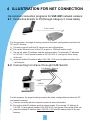
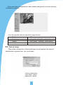
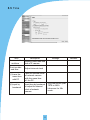
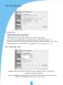
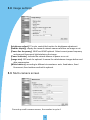
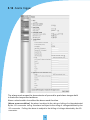
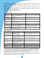
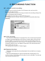
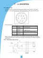
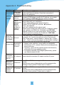
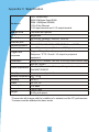
SIERA ELECTRONICS
SOUND
&
SECURITY
IP CAMERA
INSTRUCTION MANUAL
VSP 3001 IP CAMERA
www.sieraelectronics.com
PREFACE
Warning: Please read this manual carefully before
using.
Complete package should include the following items:
AC adaptor
1 pc
category 5 cross cable
1 pc
I/O terminal cable
1 pc
instruction manual
1 pc
CONTENTS
1
Introduction
2
1.1 technology support
1.2 system requirements
2
Panel description
3
2.1 front view
2.2 rear view
3
Installation
4
3.1 cautions
3.2 step
4
Illustration for net connection
5
4.1 onnect with PC directly by category 5 cable
4.2 connect to INTRANET through HUB/Switch
4.3 connect to INTERNET through HUB/Switch/Router
5
IP camera pages
7
5.1 home page
5.3 setup page
5.5 time
5.7 general user
5.9 multi-camera screen
5.11 transfer image in the timer mode
5.12 background recording function
6
Recording function
5.2 video page
5.4 network
5.6 administrator
5.8 image settings
5.10 alarm trigger
18
6.1 ActiveX control recording
6.2 FTP recording
6.3 playback function
7
I/O description
19
7.1 about I/O
7.2 example about I/O
8
Appendix
20
8.1 reset to factory default
8.2 troubleshooting
8.3 UFO specifications
1
1 INTRODUCTION
1.1 Features
Built-in web server, high quality JPEG image can be displayed through Internet
browser upon connection with Ethernet.
Motion JPEG can be up to 15 frames per second with high resolution 640x480.
Through Internet, pan/tilt heads and lens can be conveniently controlled to meet
with long-range monitoring.
Based on ASP/JAVA script, web server can provide max. platform compatibility.
Based on script CGI/ASP control, the server can offer convenience for the user to
integrate applications.
Output of E-mail,TFTP,I/O triggered with date, time and I/O input.
2 users security control, prevent unregistered users accessing the system.
Recording through IE.
Recording through FTP.
1.2 System requirements
The requirements for PC through which the network camera pages can be browsed
are as below:
Description
Item
Operation
system
Network
protocol
Interface
Windows
Windows
Windows
Windows
Windows
98
2000
ME
NT 4.0
Xp
TCP/IP Intenet Agreement(HTTP, FTP, SMTP, TCP, UDP, ICMP IP)
10/100Mbps
Internet Explorer 5.0 or later
Web browser Netscape Navigator 4.7 or later
Remarks: the CPU is recommended to be Pentium II (300MHz) or greater,
which can prevent the hardware restriction.
2
2 PANEL DESCRIPTION
2.1 Front view
Power indicator
Lens
2.2 Rear view
Ethernet indicator
Ethernet port
I/O connector
DC in jack
3
3
INSTALLATION
3.1 Cautions
Please read all safety instructions carefully before installation.
VSP-3001 IP camera should installed indoors generally. The prolonged exposure
under the sunlight or other strong lights shall accelerate the aging of the shell and
shorten the using term.
Please install the IP camera at safe site. The fall may cause the damage.
Do not place the network camera near water and assure the IP camera in a
dry circumstance with aeration.
Please use the proper input power source(input AC 220v and output DC12v/1A).
Don't leave the cables easy-touched to prevent the stumble.
Don't forcedly turn the pan/tilt head or lens to avoid the damage.
Don't touch the lens of the sensor. The fingerprint smudge shall cause the blur or no
image displayed and it also shall hurt the paint on the lens.
Please unplug the AC adaptor before cleaning the network camera. Please wipe wet
cloth only and don't use chemical and aerosol products.
Screen protection is recommended. The long-time display for same image of the
PC shall damage the monitor.
Please take the network camera to the qualified serviceman under the below cases:
A when the power supply cord or plug is damaged.
B when liquid has been spilled into the IP camera.
C
when the network camera has been dropped and damaged.
D
If the IP camera does not work normally after the setup and debug by
operating instruction.
E If the network camera exhibits an irregular condition in performance.
3.2 Installation step
A Bracket installation: aim the screw of the bracket at the hole on the bottom and turn
clockwise.
B Ethernet connectiona: use category 5 cross cable and RJ-45 linker to connect the
network camera to the net. Use category 5 straight cable to connect with HUB/
Switch or use category 5 cross cable when connecting directly to the PC.
C Confirm the specification of the AC adaptor(input AC220v,output DC12v,1A) and
connect with the network camera.
D Check if the power source indicator is enlightened. If the net has been connected
correctly, the net indicator will be enlightened within 1 second.
4
4 ILLUSTRATION FOR NET CONNECTION
He common connection programs for VSP-3001 network camera:
4.1 Connecting directly to PC(through category 5 cross cable)
Cross reticle
Users
For this program, the page browsing requires the basic configuration as below for
PC and IP camera:
A Connect correctly with the IP camera as above illustration.
B Set up the Ethernet card of the PC as auto or 10M half duplex mode.
C Set up the static IP address and the subnet masks. For example, IP address
is 192.168.1.6 and subnet masks is 255.255.255.0, and ignore other setup
of the net.
D enter the default IP address http://192.168.1.252 into the address field of the
net browser.
4.2 Connecting to Intranet through HUB/Switch
Link Builder / Switcher
Users
Reticle
Record server
For this program, the page browsing requires the basic configuration as below for PC
and network camera:
A Connect correctly with the network camera as above illustration.
B Set up the static IP address and the subnet masks. For example, IP address is
192.168.1.6 and subnet masks is 255.255.255.0, and ignore other setup of the net.
C enter the default IP address http://192.168.1.252 into the address field of the net
browser.
5
4.3 Connecting to Internet through HUB/Switch/Router
INTERNET
Users
Link Builder / Switcher
Router
Users
Reticle
Record server
For this program, not only the basic setup of PC and IP camera but also the setup of
Port Forwarding function of Router is required, so the visit for network camera besides
Intranet is accessible. The Router should have the function of Network Address
Transition(NAT) to transit the global address to local address and assign the different
external port No. to each IP camera.
4.4 Access home page of IP camera
If the IP browser is Internet Explorer, the download for ActiveX is required. So,
reset the security level of the IE as low level(Tools menu > Internet Options > Security tab
> Custom level), and then enter HTTP://192.168.1.252 to the address field to open the
home page of VSP-3001 network camera. Click the Single Camera Screen Mode, and wait
a minute till the image appearing, then set the security level to its original level.(The PC
will save the program of ActiveX after reading it, so the security level can be set to its
original level.)
If the IP browser is Netscape Navigator, please enter directly HTTP://192.168.1.252
to address field to open the home page of VSP-3001 IP camera. Click the Single Camera
Screen Mode, wait a minute and then the image will appear.
6
5 IP CAMERA PAGES
5.1 Home page
There are 3 options on home page:
1) image browsing (single camera screen/multi camera screen)
2) configuration
3) help
5.2 Video page
Click single camera screen mode, following dialogue box appears:
In put network password
Please input users and password
Webserver:
192. 168. 0. 220
Domain:
Camera
User(u)
Password(p)
Please store password into the list
Confirmation
Cannel
factory parameters
user name admin
password admin
7
Enter user name and password of administrator and general user, then following
dialogue box appears:
click left operation bars to adjust the image directly:
Brightness
17 levels
Resolution
640 480
Quality
favor clarity
Image size
x1
320 240
standard
160 120
favor motion
x2
5.3 Setup page
Click system configuration, following dialogue box will appear if the setup of
administrator or general user has been made:
In put network password
Please input users and password
Webserver:
192. 168. 0. 220
Domain:
Camera
User(u)
Password(p)
Please store password into the list
Confirmation
Cannel
factory parameters
user name admin
password admin
8
Enter user name and password of administrator, then setup page appears.
Basic setup
network
set up network parameters
time
set up date and time
administrator
set up user name and password of administrator
general user
set up user name and password of general user
image
multi-camera screen
set up image size
set up multi-camera screen
alarm trigger
Transfer
timer trigger
FTP recording
Others
restart
restart
factory default
reset to factory default
version
display version of hardware and software
9
5.4 Network
Name of network camera
4-15 English characters and 2-7 Chinese characters
Port no
The range is 1-65535(default:80). If there are 2 or more
network cameras in 1 LAN and connect to Internet or other
net through router, it will be possible to set different port no.
for each network camera.
Assign IP address
Enter IP address and submit mask assigned by
administrator to every data field.
Assign DHCP
Gateway
DNS
DHCP(Dynamic Host Configuration Protocol):please enter
the name of network camera if the system uses DHCP
server function which assign IP address automatically.
Enter the default gateway.
DNS(Domain Name Server):2 DNS IP addressescan be set up.
Please set it on first data field for single IP address.
Network camera
management server
log in for user name and password.
Bandwidth
It can restrict the transmit bandwidth.
Notes: please restart after click save to effect the settings you entered.
10
5.5 Time
item
1.current date
and time
description
settings
Display current date and
time of IP camera.
2.set up date
and time
Adjust internal clock
(1) have the
same time
with PC
Take the internal clock
of network camera
with the same time
of the PC.
(2) input by
handwork
Input time by handwork
to adjust the internal
clock of network
camera.
11
yyyy-mm-dd for year
1970 to 2039.
hh:mm:ss for 24h
mode.
remarks
5.6 Administrator
[Authentication]
[None]: anyone can access all pages.
[administrator only]:for setup page
[administrator]for setup page and [general user] for viewer page
[user name and password]:user name should be 4-15 English words or 2-7
Chinese characters. Password should be 4-15 English words or numbers. User name
and password should not be blank, [”], ['], [#], [&], [%], [=], [+], [ ], [<], [>], [ ].
5.7 General user
[general user information]: list all user name of general users. Functions for
delete and modify are offered.
[first login]:register a new general user. User name and password should not be
blank, [”], ['], [#], [&], [%], [=], [+], [ ], [<], [>], [ ].
12
5.8 Image settings
[brightness adjust]:17 levels, control the function for brightness adjustment.
[Header display]: display the name of network camera and time on image or not.
[Power line frequency]: 50HZ and 60HZ optional. Select correct power frequency
and prevent fluorescent light interfering the image.
[Power indicator]: indicate the network camera is power on or not.
[Image size]:100 levels for optional. It means the ratio between images before and
after compression.
[White balance]: according to different circumstance: auto, fixed indoor, fixed
fluorescent, fixed outdoor and hold is optional.
5.9 Multi-camera screen
Can set up multi-camera screen, the number is up to 4.
13
5.10 Alarm trigger
The alarm mode means the transmission of pre and/or post alarm images held
in the buffer to specified address.
Alarm: select enable to confirm the alarm mode function.
[Alarm occur condition]: the alarm is subject to the rising or falling of voltage detected
by the I/O connector. rising: the alarm is subject to the rising of voltage detected by the
I/O connector. Falling: the alarm is subject to the falling of voltage detected by the I/O
connector.
14
[Image setting]: select the parameters for the image which shall be transferred. Image
resolution: 640 480 / 320 240 / 160 120. Image quality: favor clarity / standard / favor
motion
[Image buffer setting]: the images held in the buffer pre and/or post alarm in short-term.
Select the image buffer frequency and the number of images which shall be transferred
into the buffer pre and/or post alarm.
[Transfer method]: select FTP or E-mail.
[FTP transfer]
Item
Description
IP address or
host name of
FTP server
port number
Host name: 1-255 English characters Should not be blank, [”], ['], [#], [&],
IP address: IP address of the
[%], [=], [+], [ ], [<], [>], [ ].
FTP server
FTP method
login ID
Remarks
1 65535
select the FTP method: active
or passive.
login ID of the FTP server: 1-15
English characters.
Password
0-15 English characters
The folder name of the FTP server
upload file path into which the file upload.
It means the naming rule for files
over write setting
Start with / and end with / ,
Root directory: / (default).
uploaded repeatedly.
[Mail transfer]
Item
Description
Remarks
Name:1-255 English
Should not be blank, [”], ['], [#], [&], [%],
SMTP server addr- characters
[=],
[+], [ ], [<], [>], [ ].
ess or host name address: IP address
Enter the user ID or not
User ID required is subject to the authentication User ID and password is not demanded
requirement of SMTP server
or not
when there is no authentication.
when send an E-mail.
Enter the user ID if the authentication
User ID
is required when send an E-mail.
Enter the password if the authentication is required when
Password
send an E-mail.
The address to receive the E-mail.
From
The address to send the E-mail. 0-63 English characters, 0-31 Chinese characters.
To
The subject of the E-mail
Subject
0-63 English characters, 0-31 Chinese characters.
The text of the E-mail
Text
Notification to be sent when alarm occurs: send or not the E-mail of notification to specified
E-mail address after alarm occurs.The E-mail of notification with no image enclosed includes
text message only. The setting for E-mail is the same as the above.
Notes: VSP-3001 network camera will only operate correctly with mail server using SMTP
(Simple Message Transfer Protocol), it is not available with the mail server accessed via web
browser (address to receive the E-mail is an exception).
15
5.11 Transfer image in the timer mode
Timer mode means sending images to specified address when the clock reaches the
pre-assigned time.
[Timer]: select the function of transferring image in the timer mode or not.
[Timer setting]: 8 timers is optional.
[Image setting]: select the parameters of images which shall be sent when it reaches
the pre-assigned time. Resolution: 640 480 / 320 240 / 160 120. Image quality:
favor clarity / standard / favor motion.
[Transfer method]: select the transfer method of the images when it reaches the
pre-assigned time by FTP or E-mail. FTP and E-mail setting refers to section
4.3.7(alarm trigger)
16
5.12 Background recording function
Background recording means sending images to background FTP server for recording
at specified intervals.
[Record]: select the background recording function or not.
[Image setting]: select the parameters of the image recorded in background. Resolution:
640 480 / 320 240 / 160 120. Image quality: favor clarity/stand/ favor motion
[image buffer frequency setting]: select the frequency for sending images for recording.
[FTP server]: refer to section 4.3.7-alarm trigger-FTP.
[Notification to be sent when record fail]: select the function to send an E-mail of
notification to specified address or not when record fail or record success after retry.
The setting for E-mail refers to section 4.3.7-alarm trigger-E-mail.
17
6 RECORDING FUNCTION
6.1 Activex control recording
ActiveX control recording function is for IE browser only, and can not for
Netscape Navigator browser.
Please right-click the mouse at the image and select the recording setting in the
option box appeared when browsing.
[File path]: select the folder in which JPEG files saved.
[File name]: enter the file mark. Actual recorder file is name(file+date+time)
[interval]
6.2 FTP recording
The FTP server is demanded. For example, Serv-U as a common type at present
is suitable for personal application with features of simple setting, strong function
and high stability. It can provide not only the function for downloading of files, but
also the general protection for system security. The setting of password and access
licensing for different users are optional. Please refer to the relevant book about
Serv-U written by lv da rong.
FTP setting refers to section 4.3.7(alarm trigger)
6.3 Playback function
The image can be played by free media-playback tool provided by our company
or ACDSee.
Open the media-playback tool, open the selected file, and play the file. The
function of delay is adjustable and the function of circle is selectable. The date and
time should be the same as PC.
18
7
I/O DESCRIPTION
7.1 About I/O
The I/O connector controls input and output of signal, and it includes 1 I/O input
terminal, 1 I/O output terminal and 1 RS-232 converter or half duplex RS-485 port.
Port description:
Port
1
2
3
4
5
6
7
8
Name
AGND
485B/RXD
485A/TXD
DGND
+12V
I/O-OUT
I/O-IN
hold
Description
analog ground
digital ground
max. output current:100mA
hold
Notes: the current(+12V) output to the peripheral equipment should not exceed
100mA, otherwise the overloading is possible to damage the AV adapter and inner
components.
7.2 Example about I/O
19
8 APPENDIX
Appendix 1: Reset to factory default
In some case, we need reset the server to factory default which can operate on
Setup Page. If the user can not login the Setup Page(such as forgetting the user name
and the password), it will be available for resetting to factory default through ARP and
PING to re-assign the IP address.
Notes: after the success of re-assigning the IP address through ARP and PING, all
other settings shall be reset to factory default except IP address setting.
Assign
IP address through ARP notes before operation:
Check the correct connection to the net and with the power for IP camera.
Obtain a unique IP address from administrator.
MAC address: there is a unique Ethernet address for every VSP-3001 IP
camera(MAC address is labeled on bottom of the IP camera). The Ethernet
address is a number with 12 figures(such as 00-0c-e8-xx-xx-xx).
Fox example, the IP address for PC is 192.168.1.6, the IP address for VSP-3001
IP camera will be set as 192.168.1.61, the MAC address is 00-0c-e8-xx-xx-xx.
The IP address of VSP-3001 network camera must have the same IP domain
with the IP address of PC(it means the same subnet mask). For example, the
IP address of PC is 192.168.1.6, the IP address of network camera is 192.168.1.61,
and the subnet mask is 255.255.255.0. If the subnet mask is 255.255.255.128 or
higher, the domain will not cover 192.168.1.61 and the setting will not be effective.
Operation procedure
1 IN operation system of Windows, open the DOS window and
operate as <start all programs accessory command
prompt> to DOS.
20
2
3
4
5
6
7
8
clear ARP: enter<arp d>.
Set up ARP: enter<arp s 192.168.1.61 00-0c-e8-00-00-01>.
PING: enter<ping t 192.168.1.61>.
Turn off the network camera.
Turn on the network camera again.
Enter Ctrl-c after Pinging, and enter <arp-d> to clear ARP
statistics.
Enter <exit> to quit the DOS.
Display as below:
C:\>arp -d
C:\>arp -s 192.168.1.61 00-0c-e8-00-00-01
C:\>ping -t 192.168.1.61
Pinging 192.168.1.61 with 32 bytes of data:
Request timed out.
Request timed out.
Request timed out.
Reply from 192.168.1.61: bytes=32 time=5ms TTL=255
Reply from 192.168.1.61: bytes=32 time=4ms TTL=255
Reply from 192.168.1.61: bytes=32 time=4ms TTL=255
Reply from 192.168.1.61: bytes=32 time=4ms TTL=255
Ping statistics for 192.168.1.61:
Packets: Sent = 7, Received = 4, Lost = 3 (42% loss),Approximate round
trip times in milli-seconds:
Minimum = 4ms, Maximum = 5ms, Average = 2ms
Control-C
^C
C:\>arp -d
C:\>exit
21
Appendix 2: Troubleshooting
Problem
Cause
the problem
of Ethernet
connection
Remedy
Please check the VSP-3001 network camera, the Hub, the
Switch and Ethernet indicator. Check their connection if
there is any abnormity.
conflict of IP Disconnect the Ethernet connection, perform PING. The
success of PING shows a conflict for IP address, so re-assign
address
the IP address of VSP-3001 network camera is needed.
Check if the IP address of VSP-3001 network camera is in the
The IP
address is in same subnet with your workstation.
1.Click start>setting>control panel>network
different
2.Select TCP/IP ADAPTOR, and click Properties .
subnet.
3.click IP address
There is
problem in
heck the IP address and the subnet mask.
setting of
Please check carefully the settings such as IP address, subnet
gateway.
mask, gateway and DNS if the workstation and VSP-3001
network camera is not in the same subnet. When necessary,
it will be required to re-assign the IP address of VSP-3001
network camera in the same subnet.
If the web browser is Internet Explorer, the download for ActiveX
when the
is
required. So, reset the security level of the IE as low level
image does ActiveX
Click Tools menu > Internet Options > Security tab > Custom
not appear
level . The PC will save the program of ActiveX after reading it,
so the security level can be set to its original level.
The frame rate is subject to the following conditions:
1 Display mode, resolution, image quality and bandwidth.
Bandwidth
image delay
2 Performance of PC, network, theme enviroment(brightness,
and other
theme and more)
reasons
3 Overmany users visit the network camera simultaneously
will prevent the image updating quickly.
4 For network cameras, if the images update slowly, please
use Switch instead of HUB.
can not
access the
network
camera via
browser
The power
LED indica- AC adaptor
Please check the standard AC adaptor and the AC power.
tor does not
light up.
When forgetting the
password of Password
setup page
Forget the IP
IP address
address of
network
camera
Use ARP and PING to re-assign the IP address of network
camera.
Reset the user name of administrator and the password after
resetting to factory default. Please refer to chapter 3.
Use ARP and PING to re-assign the IP address of network
camera.
Reset the user name of administrator and the password after
resetting to factory default. Please refer to chapter 3.
22
Appendix 3: Specification
Hardware
I mage
Image
size
CPU: 32 Bits RISC
ROM: 2M Bytes Flash ROM
RAM: 16M Bytes SDRAM
1 RJ-45 for Ethernet
1 I/O input terminal and 1 I/O output terminal
100 levels are optional
Brightness
Resolution
NTSC/PAL: 640x480, 320x240, 160x120
Ethernet port
Ethernet(10 Base-T)
Network protocol
Performance
TCP/UDP/IP, ARP, ICMP, HTTP, TFTP, Telnet, SMTP
Trigger and
response
max. 30 frames/second. Net: max. 300Kbytes/second
Trigger: I/O input/timer(frequency/motion detection
Response: TFTP / E-mail / I/O output to peripheral
equipment
Installation
Update firmware
Assign the IP address: use ARP or through administrator page
System requirement
Microsoft IE5.x or later, Netscape Navigator 4.x or later,
through TELNET
Win98/NT/2000/XP
Security
2 layer password protection
Operation temperature 0
- 40
Humidity
Power
20-80 %
Consumption
<10 watts
Dimension
100
Weight
0.60kg with power
DC12V, 1A
77mm
* Frame rate will change with the condition of a network and the PC performance.
* A sensor must be attached for alarm mode.
23