1
VAX 4000 Model 300
Technical Information
Order Number: EK-,337 AA-TI-001
VAX 4000 Model 300
Technical Information
Order Number EK-337AA-TI-001
digital equipment corporation
maynard, massachusetts
First Printing, March 1990
The information in this document is subject to change without notice and should not be
construed as a commitment by Digital Equipment Corporation.
Digital Equipment Corporation assumes no responsibility for any errors that may appear in
this document.
The software, if any, described in this document is furnished under a license and may be used
or copied only in accordance with the terms of such license. No responsibility is assumed
for the use or reliability of software or equipment that is not supplied by Digital Equipment
Corporation or its affiliated companies.
Restricted Rights: Use, duplication or disclosure by the U.S. Government is subject to
restrictions as set forth in subparagraph (c)(l)(ii) of the Rights in Technical Data and Computer
Software clause at DFARS 252.227-7013.
© Digital Equipment Corporation 1990. All rights reserved.
Printed in U.S.A
The Reader's Comments form at the end of this document requests your critical evaluation to
assist in preparing future documentation.
The following are trademarks of Digital Equipment Corporation.
COMPACTape
DDCMP
DEC
DEC direct
DECnet
DECserver
DECsystem 5400
DECUS
DECwrlter
DELNI
DELQA
DEQNA
DESTA
DSSI
!VIS
Letterprinter
Letterwriter
MicroVAX
PDP
Professional
Q-bus
ReGIS
RQDX
ScriptPrinter
ThinWire
ULTRIX
UNffiUS
VAX
VAX 4000
VAXcluster
VAX DOCUMENT
VAXELN
VAXlab
VMS
VT
mOmOOmD
lM
Amphenol is a trademark of Amphenol Corporation. Bell is a trademark of Bell telephone
companies. CHAMP is a registered trademark of AMP Inc. POSTSCRIPT is a registered
trademark of Adobe Systems Incorporated. Proprinter is a trademark of International
Business Machines Corporation. Tektronix is a registered trademark of Tektronix, Inc.
FCC NOTICE: The equipment described in this manual generates, uses, and may emit radio
frequency energy. The equipment has been type tested and found to comply with the limits for
a Class A computing device pursuant to Subpart J of Part 15 of FCC Rules, which are designed
to provide reasonable protection against such radio frequency interference when operated in
a commercial environment. Operation of this equipment in a residential area may cause
interference, in which case the user at his own expense may be required to take measures to
correct the interference.
$1351
This document was prepared using VAX DOCUMENT, Version 1.2.
Contents
Preface
vii
Chapter 1 Base System Description
1.1
1.2
1.3
1.4
1.4.1
1.4.2
1.5
1.6
1.7
System Overview. . . . . . . . . . . . . . . . . . . . . . . . . . . . . . . . . . 1-1
Firmware Overview. . . . . . . . . . . . . . . . . . . . . . . . . . . . . . . . 1-3
Power-On. . . . . . . . . . . . . . . . . . . . . . . . . . . . . . . . . . . . . . . . 1-4
Console 110 Mode Overview ................... , . . . . . . 1-4
Control Characters in Console 1/0 Mode. . . . . . . . . . . . . . 1-4
Console 110 Mode Commands. . . . . . . . . . . . . . . . . . . . . . . 1-6
Digital Storage System Interconnect (DSSI) ............. 1-13
KA670-AAIBA CPU Specifications. . . . . . . . . . . . . . . . . . . .. 1-14
MS670-BA Memory Specifications. . . . . . . . . . . . . . . . . . . .. 1-17
Chapter 2 Option Specifications
2.1
Options Overview ................................. .
2.1.1
Configuration .................................. .
2.2
Mass Storage Options ............................. .
2.2.1
KDA50 Controller .............................. .
KFQSA Storage Adapter ......................... .
2.2.2
2.2.3
nESI Controller ............................... .
2.2.4
RA60 Disk Drive
RAB1 Disk Drive
2.2.5
2.2.6
RAB2 Disk Drive
2.2.7
RA90 Disk Drive. . . . . . . . . . . . . . . . . . . . . . . . . . . . . . ..
2.2.B
RF71 Integrated Storage Assembly (ISA). . . . . . . . . . . . ..
2.2.9
RF31 Integrated Storage Assembly (ISA). . . . . . . . . . . . ..
2.2.10 RRD40 Compact-Disk Subsystem. . . . . . . . . . . . . . . . . . ..
2.2.11 TK70 Tape Drive ................................
2-2
2-2
2-3
2-4
2-5
2-6
2-7
2-B
2-10
2-11
2-12
2-13
2-14
2-16
iii
2.2.12 TQK70 Controller ...............................
2.2.13 TSV05 Tape Drive .. . . . . . . . . . . . . . . . . . . . . . . . . . . . ..
2.2.14 TSV05 Controller. . . . . . . . . . . . . . . . . . . . . . . . . . . . . . ..
2.2.15 TU81-Plus Tape Drive. . . . . . . . . . . . . . . . . . . . . . . . . . ..
Communications Options ........................... .
2.3
CXA16 Asynchronous Multiplexer (16 lines) .......... .
2.3.1
CXB16 Asynchronous Multiplexer (16 lines) .......... .
2.3.2
CXY08 Asynchronous :rvlultiplexer (8 Lines) ........... .
2.3.3
DESQA Ethernet Controller ...................... .
2.3.4
DFAOI Asynchronous Controller with Integral Modem .. .
2.3.5
DPVll Synchronous Controller .................... .
2.3.6
DSRVB DECserver 200 .......................... .
2.3.7
DSVII Synchronous Controller .................... .
2.3.8
Real-TIme Options . . . . . . . . . . . . . . . . . . . . . . . . . . . . . . . . .
2.4
AAV11-S Digital-to-Analog Converter ............... .
2.4.1
ADQ32 Analog-to-Digital Converter ................. .
2.4.2
ADVll-S Analog-to-Digital Converter ............... .
2.4.3
AXVII Controller ............................... .
2.4.4
DRQ3B Parallel Interface ........................ .
2.4.5
DRVIW Parallel Interface ........................ .
2.4.6
IBQO 1 Controller ............................... .
2.4.7
IEQ11 Controller ............................... .
2.4.8
KWV11-S Programmable Real-Time Clock ........... .
2.4.9
Printer Options ...................................
2.5
LA75 Companion Printer ..........................
2.5.1
LAI00 Letterwriter . . . . . . . . . . . . . . . . . . . . . . . . . . . . ..
2.5.2
LA120 PrinterlTerminal (DECwriter III) ..............
2.5.3
LA210Letterprinter. . . . . . . . . . . . . . . . . . . . . . . . . . . . ..
2.5.4
LGO 1 Text Printer . . . . . . . . . . . . . . . . . . .. . . . . . . . . . ..
2.5.5
LG02 Text and Graphics Printer . . . . . . . . . . . . . . . . . . ..
2.5.6
LG31 Printer ...................................
2.5.7
LJ2501LJ252 Companion Color Printers ..............
2.5.8
LN03-Series Laser Printers . . . . . . . . . . . . . . . . . . . . . . ..
2.5.9
2.5.10 LP29 Printer .. . . . . . . . . . . . . . . . . . . . . . . . . . . . . . . . ..
2.5.11 LPVl1-SA Printer Interface .......................
2.5.12 LQP02 Printer ..................................
iv
2-18
2-19
2-21
2-22
2-24
2-25
2-28
2-31
2-33
2-34
2-36
2-38
2-40
2-42
2-43
2-45
2-47
2-49
2-51
2-53
2-55
2-56
2-58
2--61
2~2
2~4
2~6
2~8
2-70
2-72
2-74
2-76
2-78
2--80
2--82
2--83
2.5.13
LQP03 Printer . . . . . . . . . . . . . . . . . . . . . . . . . . . . . . . . .. 2-85
2.6 Memory Options. . . . . . . . . . . . . . . . . . . . . . . . . . . . . . . . . .. 2-87
2.6.1
MRVI1-D Programmable Read-Only Memory Module. . .. 2-87
Chapter 3
3.1
3.2
System Expansion
Planning Your System Expansion .....................
Completing the Configuration Worksheet. . . . . . . . . . . . . . ..
3-1
3-1
Index
Examples
1-1
1-2
1-3
1-4
1-5
1-6
SHOW QBUS Display . . . . . . . . . . . . . . . . . . . . . . . . . . . . . .
SHOW DEVICE Display ............................
SHOW ETHERNET Display .........................
SHOW LANGUAGE Display . . . . . . . . . . . . . . . . . . . . . . . ..
SET LANGUAGE Command . . . . . . . . . . . . . . . . . . . . . . . ..
SET BOOT Command
1-9
1-10
1-10
1-11
1-11
1-12
Figures
1-1
3-1
VAX 4000 Model 300 Block Diagram . . . . . . . . . . . . . . . .. . .
VAX 4000 Model 300 Configuration Worksheet. . . . . . . . . . .
1-2
3-3
Tables
1-1
1-2
1-3
3-1
Console 1/0 Mode Control Characters
1-5
Console 110 Mode Commands ........................ . 1-7
Device Names ................................... . 1-12
Power Requirements .............................. . 3-4
v
(
Preface
This manual provides a summary of technical information about the VAX
4000 Model 300 system.
The manual is organized as follows:
•
Chapter 1 describes the base system and lists specifications for the
KA670-AA/-BA CPU module and MS670-BA memory module.
•
Chapter 2 describes optional components available for your system and
lists their specifications.
•
Chapter 3 contains information on expanding your system.
NOTE: You will find a Glossary in the Operation Manual to help with word
definitions and acronyms.
Conventions
The following conventions are used in this manual:
Convention
Meaning
A key name is shown enclosed to indicate that you press a named
key on the keyboard.
A sequence such as ICtrl/xl indicates that you must hold down the
key labeled Ctrl while you press another key.
BOLD
This bold type indicates user input. For example:
»> BOOT MUAO
This line shows that the user must enter BOOT MUAO at the
console prompt.
NOTE
Notes provide general information about the current topic.
CAUTION
Cautions provide information to prevent damage to equipment
or software. Read these carefully.
WARNING
Warnings provide information to prevent personal injury. Read
these carefully.
vii
Chapter 1
Base System Description
This chapter describes the VAX 4000 Model 300 base system, including the
following:
•
Power-on self-tests
•
Digital Storage System Interconnect (DSSI) architecture
•
Specifications for the KA670-AA/-BA CPU and MS670-BA memory
1.1 System Overview
All VAX 4000 Model 300 base system components are housed in a BA440
enclosure, which contains a 12-slot backplane.
Each base system contains the following:
•
A KA670-AA/-BA (IAOOO-Al-B) central processing unit (CPU) module
•
From one to four MS670-BA memory modules.
The base system modules are located in the following BA440 card slots:
•
Any MS670-BA memory modules are installed in slots 1 through 4.
•
The KA670 CPU module is installed in slot 5.
The base system operates from the KA670 CPU firmware and the controls
on the console modUle. The firmware is described in Section 1.2. Base
system operation also integrates Digital Storage System Interconnect
(DSSI) technology, which is discussed in Section 1.5.
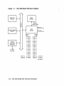
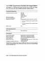
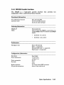
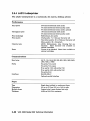
Figure 1-1 is a block diagram of the VAX 4000 Model 300 system.
Base System Description
1-1
Figure 1-1:
VAX 4000 Model 300 Block Diagram
Real-Time
Devices
Main
Memory
1/1
:::s
.0
N
Memory
Interconnect
C\I
o
Communication
Devices
tc-----I'"
Ethernet
CPU
Module
Console
TQK70
Tape Drive
Controller
MLO-003829
1-2 VAX 4000 Model 300 Technical Information
1.2 Firmware Overview
Two electrically programmable read-only memory (EPROM) chips on the
KA670 CPU module contain the firmware. This firmware consists of the
following three major programs, which perform the system power-on selftests and diagnostics:
•
A console program
•
A set of self-tests for the CPU and memory
•
A primary bootstrap program (VMB)
The console program receives control whenever the processor halts. In
a processor halt, processor control passes to the console program and
instruction execution continues. The standard VAX console functionality
is emulated whenever you execute a program in ROM.
Control passes to the firmware under any of the following conditions:
•
You power-on the system.
•
You press the Restart button.
•
You assert the Q22-bus BHALT signal by pressing the Halt button.
•
You enter a break when the Break EnablelDisable switch is set to
enable.
•
A HALT instruction is executed.
•
A system error occurs.
Base System Description
1-3
1.3 Power-On
At power-on, the console program determines the console device type and
console language, then runs the self-tests for the CPU and memory. You
choose the console language when you perform the set-up operations during
your console terminal installation procedure.
You determine the type of power-on mode by setting the Power-On Mode
switch on the CPU console module. See your VAX 4000 Dual-Host Systems
manual for the following power-on information:
•
Power-on procedures
•
Power-On Mode and Break Enable1Disable switch settings
•
Examples of successful power-on sequences
•
Boot and autoboot procedures
See the VAX 4000 '1}-oubleshooting and Diagnostics manual for examples of
problems you may encounter during power-on.
1.4 Console 1/0 Mode Overview
If you set the Break EnablelDisable switch on the console module to enable,
the console program enters Console 110 mode after the power-on self-tests
are completed successfully. The console program also enters Console 110
mode in response to any external halt condition.
CAUTION: Do not press the Restart button while the console program is
in console mode. Doing so destroys the system state and prevents normal
operation.
Console I/O mode allows you to control the system by typing commands
at the console prompt (»». You may enter these commands in either
uppercase or lowercase letters. Enter each command, then press IRetum!.
1.4.1 Control Characters in Console I/O Mode
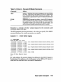
Table 1-1 lists the keypad control characters that have special meaning in
Console I/O mode.
1-4 VAX 4000 Model 300 Technical Information
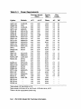
Table 1-1: Console 1/0 Mode Control Characters
Character
Action
IRetum I also <CR>
The carriage return ends a command line. No action is taken on
a command until after it is terminated by a carriage return. A
null line termlnated by a carriage return is treated as a valid, null
command. No action is taken, and the console prompts for input.
Carriage return is echoed as carriage return, line feed «CR><LF».
When you press 0 (rubout), the console deletes the previously typed
character. The resulting display differs, depending on whether the
console is a video or a hardcopy terminal.
~ (rubout)
For hardcopy terminals, the console echoes a backslash (\)
followed by the character being deleted. If you press additional
rubouts, the additional deleted characters are echoed. If you type a
non-rub out character, the console echoes another backslash, followed
by the character typed. The result is to echo the characters deleted,
surrounding them with backslashes. For example:
EXAMI;E0!!1 NE<CR>
The console echoes: EXAMI;E\E;\NE<CR>
The console sees the command line: EXAMINE<CR>
For video terminals, the previous character is erased and the
cursor is restored to its previous position.
ICtrl/AI
or l£E]
Ictrllcl
Ictrllo\ orB
ICtri/EI
Ictri/FI or El
Ictrllsl, [Ij, or
ICtrl/H I, I!J (rubout),
m
[ffiJ
Ictrllol
or
The console does not delete characters past the beginning of a
command line. If you press more rub outs than there are characters
on the line, the extra rubouts are ignored. A rubout entered on a
blank line is ignored.
Toggles insertion/overstrike mode for command line editing. By
default, the console powers up to overstrike mode.
Echoes I\C<CR> and aborts processing of a command. Has no effect
as part of a binary load data stream. Clears Ictrllsi and re-enables
output stopped by Icwo I.
Moves the cursor one position to the left.
Moves the cursor to the end of the line.
Moves the cursor one position to the right.
Recalls the previous commands.
Deletes the previously typed character. Same function as !!I
(rub out), above.
Ignores transmissions to the console until you enter ICtrilO I. Echoes
1\0 when disabling output, which is not echoed when it re-enables
output. Output is re-enabled if the console prints an error message,
or if it prompts for a command from the terminal. Output is also
enabled by entering Maintenance mode: press IBreak I or enter ICtri/C I.
Resumes output to the console terminal. Not echoed.
Base System Description
1-5
Table 1-1 (Cant.): Console I/O Mode Control Characters
Character
Action
Echoes <CR><LF>, followed by the current command line. Can be
used to improve the readability of a command line that has been
heavily edited.
Stops output to the console terminal until you enter Ictrllol. Not
echoed.
Echoes AU<CR>. Entered, but otherwise ignored if typed on an
empty line.
The console accepts Console I/O mode commands up to 80 characters long.
Longer commands produce error messages. The character count does not
include rubouts, rubbed-out characters, or the <CR> at the end of the
command.
Two or more consecutive spaces and tabs are treated as a single space.
Leading and trailing spaces and tabs are ignored. You can place command
qualifiers after the command keyword or after any symbol or number in
the command.
All numbers (addresses, data, counts) are hexadecimal, but symbolic
register names contain decimal register numbers. The hexadecimal digits
are 0 through 9 and A through F. You can use uppercase and lowercase
letters in hexadecimal numbers (A through F) and commands.
The following symbols are qualifier and argument conventions:
[] = an optional qualifier or argument
{} = a required qualifier or argument
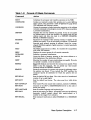
1.4.2 Console 1/0 Mode Commands
Table 1-2 lists and describes the Console I/O mode commands. You can
display the list of commands by typing HELP at the console prompt (»».
For a complete explanation of how to use the commands, along with
information on qualifiers and arguments, refer to the KA670 CPU Technical
Manual (EK-KA670-TM).
1-6 VAX 4000 Model 300 Technical Information
Table 1-2: Console 1/0 Mode Commands
Command
Action
BOOT
CONFIGURE
Initializes the processor and transfers execution to the VMB.
Invokes an interactive mode that permits you to enter Q22-bus
device names, then generates a table of Q22-bus I/O page device
CSR addresses and interrupt vectors.
Causes the processor to begin instruction execution at the address
currently contained in the program counter (PC). Does not perform
a processor initialization.
Deposits data into the address you specify. If you do not specify
an address space or data size qualifier, the console uses the last
address space and data size used in a DEPOSIT, EXAMINE,
MOVE, or SEARCH command.
Examines the contents of the memory location or register of the
address you specify. If you do not specify an address, + is assumed.
Searches main memory starting at address 0 (zero) for a pagealigned 128-Kbyte segment of good memory, or a restart parameter
block (RPB).
The HALT command has no effect. It is included for compatibility
with other VAX consoles.
Displays the correct syntax for all console commands.
Performs a processor initialization.
Copies the block of memory starting at the source address to a
block beginning at the destination address.
Executes the number of macro instructions you specify. If you do
not specify a number, 1 (one) is assumed.
Repeatedly displays and executes the command you specify. Press
Icwc I to stop the command. You can specify any valid console
command except the REPEAT command.
Finds all occurrences of a pattern and reports the addresses where
the pattern was found. If you include the !NOT qualifier, the
command reports all addresses for which the pattern did not
match.
Sets the default R5 boot flags. The value must be a hexadecimal
number of up to eight digits.
Sets the default boot device. The value must be a valid device
name.
Sets Control-P as the console halt condition, instead of a BREAK.
Connects to the DUP or MAINTENANCE driver on the node or
device you specify.
Sets the console language and keyboard type.
Sets the halt action you define. Acceptable values are the following
keywords: default, restart, reboot, halt, restartJeboot, or a
number in the range 0 to 4 inclusive.
Sets command recall state to either ENABLED (1) or DISABLED
CONTINUE
DEPOSIT
EXAMINE
FIND
HALT
HELP
INITIALIZE
MOVE
NEXT
REPEAT
SEARCH
SETBFLAG
SET BOOT
SET CONTROLP
SET HOST
SET LANGUAGE
SET HALT
SET RECALL
(0).
Base System Description
1-7
Table 1-2 (Cont.): Console 1/0 Mode Commands
Command
Action
SHOWBFLAG
SHOW BOOT
SHOW CONTROLP
Displays the default R5 boot flags.
Displays the default boot device.
Shows the current state of Control-P halt recognition, either
ENABLED or DISABLED.
Displays all devices displayed by the SHOW DSSI, SHOW
ETHERNET, and SHOW UQSSP commands.
Displays the status of all nodes that can be found on the DSSI
bus. For each node on the DSSI bus. the firmware displays the
node number, the node name. and the boot name and type of the
device, if available. Does not indicate whether the device contains
a bootable image.
Displays the hardware Ethernet address for all Ethernet adapters
that can be found, both on-board and on the Q22-bus.
Displays console language and keyboard type.
Displays main memory configuration, board by board.
Displays all Q22-bus lIO addresses that respond to an aligned
word read, plus vector and device name information. For each
address, the console displays the address in the VAX lIO space in
hexadecimal, the address as it would appear in the Q22-bus lIO
space in octal, and the word that was read in hexadecimal. Also
displays the vector that you should set up, and device name or
names that could be associated with the CSR.
Displays the current state of command recall, either ENABLED or
DISABLED.
Displays the halt action. Keywords include: default, restart,
reboot, halt, restart_reboot or a number in the range 0 to 4
inclusive.
Displays all RLOl and RL02 disks that appear on the Q22-bus.
Shows any SCSI devices in the system.
Shows any virtual addresses that map to the specified physical
address.
Displays the status of all disks and tapes that can be found on the
Q22-bus that support the UQSSP protocol. For each such disk or
tape on the Q22-bus, the firmware displays the controller number.
the controller CSR address. and the boot name and type of each
device connected to the controller. The command does not indicate
whether the device contains a bootable image.
Displays the current firmware version.
Starts instruction execution at the address you specify. If you
do not give an address. the current program counter is used. If
memory mapping is enabled, macro instructions are executed from
virtual memory, and the address is treated as a virtual address.
Equivalent to a DEPOSIT to PC, followed by a CONTINUE. Does
not perform a processor initialization.
SHOW DEVICE
SHOW DSSI
SHOW ETHERNET
SHOW LANGUAGE
SHOW MEMORY
SHOWQBUS
SHOW RECALL
SHOW HALT
SHOWRLV12
SHOW SCSI
SHOW TRANSLATION
SHOWUQSSP
SHOW VERSION
START
1-8 VAX 4000 Model 300 Technical Information
Table 1-2 (Cont.): Console I/O Mode Commands
Command
Action
TEST
Invokes a diagnostic test program specified by the test number
you enter. If you enter a test number of 0 (zero), all tests allowed
to be executed from the console terminal are executed. The
console accepts an optional list of up to five additional hexadecimal
arguments.
Performs an 110 bus reset, by writing a 1 (one) to IPR 55 (decimal).
Loads or unloads (that is, writes to memory or reads from memory)
the specified number of data bytes through the console serial line
(regardless of console type), starting at the specified address. For
use by automatic systems communicating with the console.
UNJAM
X
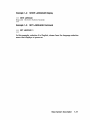
Examples 1-1 through 1-6 show sample displays for the commonly used
commands SHOW and SET.
The SET command sets the parameter to the value you specify. The SHOW
command displays the console parameter you specify.
Example 1-1: SHOW QBUS Display
»> SHOW gBOS
Scan of Qbus I/O Space
-200000DC (760334 )
0000
-200000DE (760336)
OAAO
-200000EO (760340)
0000
-200000E2 (760342)
OAAO
-200000E4 (760344)
0000
-200000E6 (760346)
OAAO
0000
-20001468 (772150)
OAAO
-2000146A (772152)
-20001F40 (777500)
0020
(300) RQDX3/KDA50/RRD50/RQC25/KFQSA-DISK
(304 ) RQDX3/KDA50/RRD50/RQC25/KFQSA-DISK
(310) RQDX3/KDA50/RRD50/RQC25/KFQSA-DISK
(154) RQDX3/KDA50/RRD50/RQC25/KFQSA-DISK
(004 ) IPCR
Scan of Qbus Memory Space
»>
For each address, the console displays the address in the VAX 1/0 space in
hexadecimal, the address as it would appear in the Q22-bus I/O space in
octal, and the word data that was read in hexadecimal.
Base System DeSCription
1-9
Example 1-2:
SHOW DEVICE Display
»>SHOW DEVICE
DSSI Bus 0 Node
-DIA10 (RF7l)
DSSI Bus 0 Node
-DIAll (RF7l)
DSSI Bus 0 Node
-DIA12 (RF71)
DSSI Bus 0 Node
0 (BARNEY)
1 (BETTY)
2 (FRED)
7 (*)
DSSI Bus 1 Node 0 (SNEEZY)
-DIBO (RF71)
DSSI Bus 1 Node 1 (DOPEY)
-DIBl (RF71)
DSSI Bus 1 Node 2 (SLEEPY)
-DIB2 (RF71)
DSSI Bus 1 Node 3 (GRUMPY)
-DIB3 (RF71)
DSSI Bus 1 Node 4 (BASHFUL)
-DIB4 (RF71)
DSSI Bus 1 Node 5 (HAPPY)
-DIB5 (RF71)
DSSI Bus 1 Node 6 (DOC)
-DIB6 (RF71)
DSSI Bus 1 Node 7 (*)
UQSSP Tape Controller 0 (774500)
-MUAO (TK70)
Ethernet Adapter
-EZAO (OB-00-2B-06-10-42)
For each device, the console displays the controller, the node, and the
address on the first line, and the device name and option on the second
line.
.
Example 1-3:
SHOW ETHERNET Display
»> SHOW ETHERNET
Ethernet Adapter
-EZAO (OB-00-2B-OB-29-14)
1-10 VAX 4000 Model 300 Technical Information
Example 1-4: SHOW LANGUAGE Display
»> SHOW LANGUAGE
English (United States/Canada)
»>
Example 1-5:
SET LANGUAGE Command
»> SET LANGUAGE 5
»>
In this example, selection 5 is English, chosen from the language selection
menu that displays at power-on.
Base System Description
1-11
Example 1--6:
SET BOOT Command
»> SET BOOT NOAO
»>
In this example, entering MUAO sets the tape drive as the default boot
device.
Table 1-3: Device Names
Device Logical
Name
Device Type
Controller/Adapter
RF -series ISA
Embedded DSSI host adapter
(part of CPU)
DImn l
RF -series ISA
KFQSA storage adapter
DUcn2
TK70 tape drive
TQK70
MUcnB
PROM (programmable read
only memory)
MRVll module
PRAn
Ethernet adapter
On-board (part of CPU)
EZAO
Ethernet adapter
DESQA Ethernet controller
XQAn
RA-series drives
KDA50
DUcn2
1m = nSSI bus adapter (A = first bus (0), B = second bus (1), etc.)
n = unit number
When under operating system control, DIBn devices are recognized as DIAn devices.
2c = MSCP controller designator (A = first, B = second, etc.)
n = unit number
Bc = TMSCP controller designator (A = first, B = second, etc.)
n = unit number
1-12 VAX 4000 Model 300 Technical Information
1.5 Digital Storage System Interconnect (OSSI)
The KA670 CPU module contains two DSSI bus interfaces that are
dedicated to the mass storage devices in the VAX 4000 Model 300 system.
(See Figure 1-1 for the VAX 4000 Model 300 block diagram.)
Each DSSI bus interface connects to a DSSI integrated storage assembly
(lSA). An ISA is a 5.25-inch integrated storage element (lSE) that is housed
in a special mounting bracket for simplified enclosure installation and
upgrading.
Each DSSI bus has the following characteristics:
•
A 4-Mbytes-per-second bandwidth
•
Up to eight nodes (one interface and up to seven ISAs)
•
Eight data lines
•
One parity line
•
Eight control lines
DSSI architecture improves system performance as follows:
•
The DSSI bus handles all mass storage transactions.
•
Mass storage devices can act independently, since each device contains
its own controller. Several devices can work simultaneously.
The two DSSI bus interfaces support up to 16 nodes. These 16 nodes include
the 2 DSSI interfaces and 14 ISAs.
An ISA can maintain connections to more than one DSSI interface. In a
dual-host configuration in which multiple CPUs can be connected to the
DSSI bus interfaces, two VAX 4000 Model 300 systems have access to each
ISA on the DSSI busses.
For more information about dual hosting VAX 4000 Model 300 systems
and the advantages of such configurations, see the section on dual-host
capability in the VAX 4000 Model 300 Operation manual.
Base System Description
1-13
1.6 KAS70-AAIBA CPU Specifications
The VAX 4000 Model 300 system uses the KA670-AA central processing
unit.
The VAXserver 4000 Model 300 uses the KA670-BA central
processing unit.
Central Processing Unit
Addressing modes
Clock rate
Data path width
Number of data types
Number of instructions
General purpose registers
PDP-ll compatibility mode
Time bases
I/O bus interface
Backplane termination
General register: 8
143 MHz
64 bits
Hardware: 9
Software emulated: 7
Hardware: 272
Software emulated: 32
16 (32-bit wide)
Program counter: 4
Index: 9
Emulated in software
Time-of-year clock: 1 (battery backup)
Interval timer: 1 (10 milliseconds)
Programmable timers: 2
One Q22-bus interface with 8192 entry map
240 n
Memory Management and Control
Page size
Virtual address space
Physical memory space
Number of memory modules
512 bytes
4 gigabytes
512 Mbytes
4 maximum
Performance
Instruction prefetch buffer size
On-chip cache
Size
Speed
Associativity
On-board cache
Size
Speed
12 bytes
2 Kbyte
28 nanoseconds
Direct mapped
128 Kbytes
84 nanoseconds
1-14 VAX 4000 Model 300 Technical Information
Performance
Associativity
Translation buffer
Size
Associativity
Q22-bus address translation
map cache
Size
Associativity
1/0 bus buffer size
Input
Output
Maximum 1/0 bandwidth
Block mode DMA read
Block mode DMA write
Direct mapped
64 entry
Fully associative
16 entry
Fully associative
32 bytes
4 bytes
2.4 Mbyteslsecond
3.3 Mbyteslsecond
Ethernet Port
Supported protocols
Supported media types
Data path width
Maximum bandwidth
Buffer size
Transmit buffer
Receiver buffer
Ethernet V2.0
Standard or ThinWire
1 bit
10 Mbitslsecond
128 bytes/second
128 bytes/second
Digital Storage System Interconnect (DSSI) Connector
Maximum number of supported devices
Data path width
Maximum bandwidth
Maximum queue 1/0
Buffer size
Transmit buffer
Receiver buffer
14
8 bits
4 Mbyteslsecond
800/second
128 bytes/second
128 bytes/second
Console Serial Line
Interface standards
EIA RS-423-AlCCITT V. 10 X.26
EIA RS-232-C/CCITT V.28
DEC-423
Base System Description
1-15
Console Serial Line
Data format
Baud rates
1 start bit, 8 data bits, 0 parity bits, 1 stop
bit
300; 600; 1200; 2400; 4800; 9600; 19,200;
38,400
Ordering Information
Included as part of base system
Configuration Information
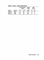
Form factor
Power requirements
Powerconsuxaption
Bus loads
Quad height
+5 Vdc, 7.4A
+3.3 Vdc, 0.27 A
+12 Vdc, 0.35 A
-12 Vdc, 0.04 A
42.6W
4.0 ac
1.0 dc
Operating System Support
VMS
Version 5.3-2 and later
VAXELN
Diagnostic Support
MicroVAX Diagnostic Monitor
Self-tests
Release 131 and later
Yes
Related Documentation
EK-KA670-TM
KA670 CPU Technical Manual
1-16 VAX 4000 Model 300 Technical Information
1.7 MS670-BA Memory Specifications
The MS670-BA is a 32-Mbyte memory module that provides memory
expansion for the KA.670-AA/-BA CPU module. The MS670-BA modules
interface with the CPU through the MS670 local memory interconnect.
You can use up to four MS670-BA modules in the VAX 4000 Model 300
system.
Operating system support and diagnostic support are the same as for the
KA670 CPU module, as listed in Section 1.6.
Performance
Memory Cycle Time at 28 nanoseconds:
Memory Read (Octaword):
Page mode memory read
Non-page mode memory read
Memory write (Octaword):
Page mode memory write
Non-page mode memory write
Memory masked write (Longword):
Page mode memory write
Non-page mode memory write
392 nanoseconds
756 nanoseconds
308 nanoseconds
504 nanoseconds
399 nanoseconds
504 nanoseconds
Ordering lDformation
MS670-BA
32-Mbyte field-installed kit
Configuration Information
Form factor
Power requirements
Power consumption
Bus loads
Quad height
+5 Vdc, 2.52 A
+12 Vdc, 0.0 A
12.6W
0.0 ac
0.0 dc
Base System Description
1-17
Chapter 2
Option Specifications
This chapter lists specifications for the options currently supported in the
VAX. 4000 Model 300 system, grouped as follows:
•
•
•
•
•
Mass storage
Communications
Real-time
Printer
Memory
The specifications appear in alphanumerical order within each of the above
groups. All weights are approximate.
Some of the options are already installed in your system. If you want to add
other options, your Digital sales representative can advise you. Chapter 3
offers some guidelines on determining what options you can add.
Option Specifications
2-1
2.1 Options Overview
The option specifications include the following, where applicable:
•
Functional information
•
Ordering information
•
Performance
•
Configuration information
•
Related documentation
Unless otherwise noted, operating system support and diagnostic support
for all options are the same as for the KA670 CPU module, as listed in
Section 1.6.
2.1.1 Configuration
Options must be properly configured so that the system recognizes them.
Each option in a system has a device address, commonly referred to as
a control and status register (CSR) address, and an interrupt vector that
must be set when the option is installed. Options are usually configured by
setting switches or jumpers on modules already configured at the factory
or Digital service representatives configure the option when they install it
in your system.
Self-maintenance customers can find information on setting CSR addresses
and interrupt vectors in the Microsystems Options volwne of the Entry
Systems Service kit.
2-2 VAX 4000 Model 300 Technical Information
2.2 Mass Storage Options
The VAX 4000 Model 300 system supports the following mass storage
devices:
•
Internal to the BA440 enclosure:
TK70 tape drive
RF -series integrated storage assembly (lSA)
•
External to the BA440 enclosure:
RRD40 compact disk subsystem (tabletop)
TU81-Plus tape
TSV05 tape
RA-series disks
Four RF-series drives are supported by one KDA50 controller. The system
supports up to eight RF -series drives, with two KDA50 controllers.
Up to four RF-series ISAs can be installed in your system. The CPU
communicates with the ISAs through a Digital Storage System Interconnect
(DSSI) adapter, which is built into the CPU. Your VAX 4000 system has two
DSSI adapters, and hence, two separate DSSI busses. Each DSSI bus is
capable of supporting seven integrated storage assemblies.
You can put only two disk controllers in the Q-bus backplane, two KDA50s,
two KFQSAs, or one of each.
Option Specifications
2-3
2.2.1 KDA50 Controller
The KDA50 is an intelligent controller that interfaces with up to four SDIcompatible mass storage devices on the Q22-bus.
Functional Information
Controller protocol
Bad block replacement
Supported drives
Drives per controller
Controllers per system
Drive interconnect
MSCP
Software dependent
~60,~70,~81,~82,~90
4
1 maximum for VMS 5.1
2 maximum for VMS V5.2 and later
Transformer-coupled radial
Ordering Information
KDA50-SF
KDA50-SG
~-series disk drive controller, controls up to a
maximum of four RA-series devices 1
Second KDA50 controller, for support of up to four
~-series devices, uses three Q-bus slots 1
Performance
ReadIWrite data transfers
Data buffering
Command buffering
Up to 16-byte block mode DMA
32 Kbytes
20 command and response ring buffers
Configuration Information
Form factor
Power requirements
Power consumption
Bus loads
Two quad height
+5 Vdc, 13.5 A (typical)
+12 Vdc, 0.03 A (typical)
67.86 W
3.0 ac
0.5 dc
Related Documentation
EK-KDA5Q-UG
1Field
KDA50-Q User's Guide
installed option.
2-4 VAX 4000 Model 300 Technical Information
2.2.2 KFQSA Storage Adapter
The KFQSA is an intelligent storage adapter that allows Q22-bus systems
to communicate with storage peripherals based on the Digital Storage
System Interconnect (DSS!).
Functional Information
Controller protocol
Supported drive
Drives per adapter
Drive interconnect
Controllers per system
SSP: to and from Q22-bus host
DSSI: to and from ISAs
RF-series !SAs
7
Direct
2 maximum
Ordering Information
KFQSA-SG
RF-series ISA adapter, controls up to a maximum
of 7 RF-series ISAs
Performance
Peak transfer rate
Sustained transfer rate
I/O request throughput
Error detection
4 Mbytes/second
1.5 Mbytes/second
190 I/O requests/second (single-sector reads)
DSSI bus parity and check character,
transmissions
all
Configuration Information
Form factor
Power requirements
Power consumption
Bus loads
Quad height
+5 Vdc, 5.5 A (typical)
27.5 W
4.4 ac
0.5 dc
Related Documentation
EK-KFQSA-IN
KFQ Storage Adapter Installation and User
Manual
Option Specifications
2-5
2.2.3 KLESI Controller
The KLESI-SA is a controller that interfaces with the TU81-Plus tape
drive on the Q22-bus.
Functional Information
Controller protocol
Supported drive
Drives per adapter
Drive interconnect
Controllers per system
TMSCP
TU81-Plus
1
Direct
1 maximum
Ordering Information
Included with the TUa1-Plus tape drive
Configuration Information
Form factor
Power requirements
Power consumption
Bus loads
Dual
+5 Vdc, 4.0 A (typical)
+12 Vdc, 0.0 A (typical)
20.0W
0.5 ac
1.0 dc
Related Documentation
EK-LESIB-UG
KLESI-B Module User's and Installation Guide
2-6 VAX 4000 Model 300 Technical Information
2.2.4 RA60 Disk Drive
The RA60 disk drive is a high-capacity removable disk drive that provides
205 Mbytes of formatted storage space. The VAX 4000 Model 300 supports
these drives in separate storage expansion enclosures only.
Storage Capacity
User capacity
User capacity (blocks)
205 Mbytes
400 t 176
Ordering Information
RA60-AF
BC26V-06
RA60 disk drive and cables
Interconnect cable with connector block
Performance
Average seek time
Average rotational latency
Average access time
Peak transfer rate
41.67 milliseconds
8.33 milliseconds
50.30 milliseconds
15.84 Mbitslsecond
Physical Specifications
Height
Width
Depth
Weight
26.52
48.26
85.09
68.95
cm (10.44 in)
cm (19 in)
em (33.75 in)
kg (152 lb)
Configuration Information
Form factor
10.5-in hight full rack width
Related Documentation
EK-ORA60-UG
RA60 Disk Drive User's Guide
Option Specifications
2-7
2.2.5 RA81 Disk Drive
The RA8l disk drive is a high-capacity fixed-disk drive that provides 456
Mbytes of formatted storage space. The VAX 4000 Model 300 supports these
drives in separate storage expansion enclosures only.
Storage Capacity
User capacity
User capacity (blocks)
456 Mbytes
891,070
Ordering Information
RA81-HA
RA8l-HD
RQA8l-AA
RQA81-AD
BC26V-6D
RA8l disk drive (120 V)
RA8l disk drive (240 V)
RA8l disk drive (120 V) with KDA50 controller
and BC26V-06 cable
RA8l disk drive (240 V) with KDA50 controller
and BC26V-6D cable
Interconnect cable with connector block
Performance
Average seek time
Average rotational latency
Average access time
Peak transfer rate
28.00 milliseconds
8.32 milliseconds
36.30 milliseconds
17.4 Mbitslsecond
Physical Specifications
Height
Width
Depth
Weight
26.3
44.5
67.3
61.2
em (10.38 in)
em (17.5 in)
em (26.5 in)
kg (135 Ib)
Configuration Information
Form. factor
10.5-in high, full rack width
2-8 VAX 4000 Model 300 Technical Information
Related Documentation
EK-ORA81-SV
EK-ORA81-UG
RA81 Disk Drive Service Guide
RA81 Disk Drive User's Guide
Option Specifications
2-9
2.2.6 RA82 Disk Drive
The RA.82 disk drive is a high-capacity fixed-disk drive that provides 623
Mbytes of formatted storage space. The VAX 4000 Model 300 supports these
drives in separate storage expansion enclosures only.
Storage Capacity
User capacity
User capacity (blocks)
623 Mbytes
1,216,660
Ordering Information
RA82-AA
RA82-AD
BC26V-06
RA.82 rUsk drive (120 V) with one BC26V-12 cable
RA.82 disk drive (240 V) with one BC26V-12 cable
Interconnect cable with connector block
Performance
Average seek time
Average rotational latency
Average access time
Peak transfer rate
24.00 milliseconds
8.33 milliseconds
32.33 milliseconds
19.2 Mhits/second
Physical Specifications
Height
Width
Depth
Weight
26.3
44.5
67.3
61.2
em (10.38 in)
em (17.5 in)
em (26.5 in)
kg (135 lb)
Configuration Information
Form factor
10.5-in high, full rack width
Related Documentation
EK-ORA82-SV
EK-ORA82-UG
RA.82 Disk Drive Service Guide
RA82 Disk Drive User's Guide
2-10 VAX 4000 Model 300 Technical Information
2.2.7 RA90 Disk Drive
The RA90 disk drive is a high-capacity fixed-disk drive that provides 1.2
gigabytes of formatted storage space. The VAX 4000 Model 300 supports
these drives in separate storage expansion enclosures only.
Storage Capacity
User capacity
User capacity (blocks)
1.2 gigabytes
2,376,153
Ordering Information
RA90-NA
RA90-ND
BC26V-12
RA90 disk drive (120 V)
RA90 disk drive (240 V)
Interconnect cable with connector block
Performance
Average seek time
Average access time
Peak transfer rate
17.5 milliseconds
8.33 milliseconds
22.1 Mbitslsecond
Physical Specifications
Height
Width
Depth
Weight
26.6 em (10.4 in)
23.0 em (8.7 in)
68.5 em (27.0 in)
13.6 kg (62 lb)
Configuration Information
Form factor
10.5-in high, full rack width
Related Documentation
EK-ORA90-SV
EK-0RA90-UG
RA90 Disk Drive Service Guide
RA90 Disk Drive User's Guide
Option Specifications
2-11
2.2.8 RF71 Integrated Storage Assembly (ISA)
The RF71 is a DSSI integrated storage assembly (ISA) that provides 400
Mbytes offormatted storage space. An ISAis a 5.25-inch integrated storage
element (ISE) that is housed in a special mounting bracket for simplified
installation and upgrading.
Storage Capacity
User capacity
User capacity (blocks)
400 Mbytes
781,440
Ordering Information
RF71E-AA
400 Mbyte DSSI ISA
Performance
Average random seek time
Average rotational latency
Average access time
Peak transfer rate
19.20 milliseconds
8.33 milliseconds
34.2 milliseconds
1.5 Mbitslsecond
Physical Specifications
Height
Width
Depth
Weight
7.75 em (3.05 in)
14.60 cm (5.75 in)
20.75 cm (8.17 in)
4.09 kg (9.0 lb)
Configuration Information
Form factor
Power requirements
Power consumption
Standard 10.5-in footprint
+5 Vdc, 1.25 A
+12 Vdc, 1.64 A
25.93 W
Related Documentation
EK-RF71D-IM
EK-RF71D-UG
RF71 Disk Drive Installation Manual
RF71 Disk Drive User's Guide
2-12 VAX 4000 Model 300 Technical Information
2.2.9 RF31 Integrated Storage Assembly (ISA)
The RF31 is a DSSI integrated storage assembly (ISA) that provides 381
Mbytes of formatted storage space. An ISA is a 5.25-inch integrated storage
element (lSE) that is housed in a special mounting bracket for simplified
installation and upgrading.
Storage Capacity
Data storage capacity
381 Mbytes, formatted
Ordering Information
RF31E-AF
381 Mbyte half-height DSSI ISA
Performance
Average seek time
Average access time
Peak transfer rate
14.7 milliseconds
23 milliseconds
4.0 Mbyteslseeond
Physical Specifications
Height
Width
Depth
Weight
4.10 em (1.75 in)
14.60 em (5.75 in)
20.45 em (8.25 in)
1.81 kg (4.0 Ib)
Configuration Information
Form factor
Power requirements
Power consumption
Standard 5.25-in footprint
+5 Vdc, LOA
+12 Vdc, 2.80 A
38.6W
Option Specifications
2-13
2.2.10 RRD40 Compact-Disk Subsystem
The RRD40 is a CD reader that retrieves data in fixed-length blocks from
removable compact-disk media.
Functional Information
Modes
Orientation
Idle mode
Operation mode: search, normal play
Horizontal
Ordering Information
RRD40-SF
Field-installed tabletop CDROM drive with controller
Performance
Motor stop time
Motor start time
Formatted capacity
Average transfer rate
Average latency
Initialization time
30% of nominal speed within 30 seconds maximumt 5 seconds typical
90% of nominal speed within 20 seconds maximu~ less than 11 seconds typical
525 Mbytes with maximum of 600 Mbytes (65
minutes)
153.6 Kbyteslsecond t mode 1
176.4 Kbyteslsecond t mode 2
60 JlS maximum at inner track
155 }lS at outer track
15 seconds maximum to sector zero
Physical Specifications
Height
Width
Depth
Weight
27.6 em. (11.02 in)
8.18 em. (3.27 in)
22.7 em. (9.06 in)
5.0 kg (11.0 lb)
Configuration Information
Power consumption
19.2 W maximum
Play mode: 18 W maximum
2-14 VAX 4000 Model 300 Technical Information
Related Documentation
EK-RRD40-0M
EK-RRD40-SU
RRD40 Disk Drive Owner's Manual
RRD40 MicroVAX Monitor User's Guide Updates
Option Specifications
2-15
2.2.11 TK70 Tape Drive
The TK70 is a streaming-tape-drive subsystem that can store up to 296
Mbytes on a tape cartridge for backup data storage. The TK70 can read
data from cartridges recorded on a TK50 drive, but cannot write data to
cartridges recorded on a TK50 drive.
Functional Information
Recording media
Tape dimensions
Mode of operation
Recording method
Recording density
Number of tracks
Storage capacity
Magnetic tape
1.27 em (0.5 in) wide, 182.9 m (600 ft) long
Streaming
Serpentine
10,000 bits/in
48
296 Mbytes formatted
Ordering Information
TK70E-AF
TKQK70-SF
296 Mbyte cartridge tape drive
Controller for TK70E-AF
Performance
Tape start time
Tape stop time
Tape speed
Streaming data rate
Access time (from insertion of tape)
TK50 mode (read-only)
TK70 mode
325 milliseconds maximum
200 milliseconds maximum
390 cm/second (100 in/second)
125 Kbytes/second
35 minutes maximum
60 minutes maximum
Physical Specifications
Height
Width
Depth
Weight
8.25 em (3.25 in)
14.60 cm (5.70 in)
21.44 cm (8.44 in)
3.07 kg (5.0 lb)
2-16 VAX 4000 Model 300 Technical Information
Configuration Information
Form factor
Power requirements
Standard 5.25-in footprint
+5 Vdc, 1.5 A
+12 Vdc, 2.4 A
Power consumption
Bus loads
36.3W
0.0 ac
0.0 dc
Related Documentation
EK-OTK70-OM
EK-OTK70-TM
EK-OTK70--SM
TK70 Tape Drive Subsystem Owner's
Manual
TK70 Tape Drive Subsystem Technical
Manual
TK70 Tape Drive Subsystem Service
Manual
Option Specifications
2-17
2.2.12 TQK70 Controller
The TQK70 controller module provides the interface between the TK70 tape
drive and the Q22-bus.
Functional Information
Controller protocol
Supported drive
Drives per controller
Drive interconnect
Controllers per system
TMSCP
TK70
1
Direct
1 maximum
Ordering Information
TQK70-AA
Controller for TK70E-AF
Performance
Data throughput rate
ReadlWrite data transfers
Buffer size
125 Kbytes/second
Up to 16-word burst mode DMA, truncated to 8word burst mode if another device is requesting
the bus
64 Kbytes
Configuration Information
Form factor
Power requirements
Power consumption
Bus loads
Dual height
+5 Vdc, 3.5 A
+12 Vdc, 0.0 A
17.5W
4.3 ac
0.5 dc
Related Documentation
EK-OTK70-0M
TK70 Tape Drive Subsystem Owner's
Manual
2-18 VAX 4000 Model 300 Technical Information
2.2.13 TSV05 Tape Drive
The TSV05 is a magnetic streaming-tape-drive that provides 40.5 Mbytes
of backup data storage. The TSV05 reads or writes up to 160 Kbytes per
second in standard ANSI format.
Functional Information
Recording media
Tape dimensions
Mode of operation
Recording method
Recording density
Number of tracks
Storage capacity
Magnetic tape
1.27 em (0.5 in) wide, 731 m (2400 ft) long
Streaming
Phase encoded (FE)
1600 bits/in
9
40 Mbytes formatted
Ordering Information
TSV05-SB
TSV05 tape drive subsystem
Performance
Handling
Tape velocity
Maximum data transfer rate
Rewind time (731 m (2400 ft) tape on
26.7 cm (10.5 in) reel)
Bidirectional reel-to-reel with compliance arm
64 or 254 em/second (25 or 100 in/second)
40 or 160 Kbyteslsecond
2.8 minutes
Physical Specifications
Height
Width
Depth
Weight
23.0 em (8.75 in)
43 em (17 in)
62 cm (24.5 in)
36 kg (80 lb)
Configuration Information
Form factor
10.5-in high, full rack width
Option Specifications
2-19
Related Documentation
EK-TSV05-UG
EK-TSV05-TM
TSV05 Tape Transport System User's Guide
TSV05 Tape Transport Subsystem Technical
Manual
2-20 VAX 4000 Model 300 Technical Information
2.2.14 TSV05 Controller
The TSV05 tape drive controller interfaces the TSV05 tape drive to the
Q22-bus.
Functional Information
Controller protocol
Supported drive
Drives per controller
Drive interconnect
Controller unique
TSVOS
1
Direct
Ordering Information
TSV05-SB
TSVOS tape drive subsystem
Performance
Buffer size
3.S Kbytes
Configuration Information
Form factor
Power requirements
Power consumption
Bus loads
Quad height
+S Vdc, 6.S A (typical)
+12 Vdc, 0.0 A (typical)
32.SW
2.4 ac
1.0 dc
Related Documentation
EK-TSV05-UG
TSVOS Tape Transport System User's Guide
Option Specifications
2-21
2.2.15 TU81-Plus Tape Drive
The TU81-Plus is a reel-to-reel tape drive mounted in a 101.6-cm (40in) cabinet. The drive supports two industry-standard recording methods:
group coded recording (GCR) and phase encoded (PE).
Storage Capacity
PE unformatted
PE formatted
GCR unformatted
GCR formatted
45.3 Mbytes
40.0 Mbytes
177 Mbytes
140 Mbytes
Functional Specifications
Recording media
Tape dimensions
Mode of operation
Recording methods
Recording density
Number of tracks
Magnetic tape
1.27 em (0.5 in) wide, 731 m (2400 ft) long
Streaming
Group code recording (GCR)
Phase encoded (PE)
6250 bits/in (GCR)
1600 bits/in (PE)
9
Ordering Information
TUS1E-DA
TUS1E-DB
TUSl-Plus tape drive, KLESI controller for 120 V
TUSl-Plus tape drive, KLESI controller for 240 V
Performance
Handling
Tape velocity
High speed
Low speed
Channel data transfer rate
PE high speed
PE low speed
GCR high speed
GCR low speed
Rewind time (731.5 m (2400 ft) tape on
26.7 cm (10.5 in) reel)
2-22
Bidirectional reel-to-reel
190.5 cm/second (75 inlsecond)
63.5 cmIsecond (25 inlsecond)
120 Kbyteslsecond
40 Kbyteslsecond
469 Kbyteslsecond
156 Kbyteslsecond
2.75 minutes maximum
VAX 4000 Model 300 Technical Information
Physical Specifications
Height
Width
Depth
Weight
105.8 em (41.7 in)
54.6 em (21.5 in)
76.2 em (30.0 in)
139 kg (295 lb)
Related Documentation
EK-TU81E-UG
TU81-Plus Tape Subsystem User's Guide
Option Specifications
2-23
2.3 Communications Options
The VAX 4000 Model 300 system supports the following communications
options:
•
CXA16 asynchronous multiplexer (16 lines)
•
CXB16 asynchronous multiplexer (16 lines)
•
CXY08 asynchronous multiplexer (8 lines)
•
DESQA Ethernet controller
•
DFAOI asynchronous controller with integral modem
•
DPVll synchronous interface
•
DSRVB DECserver 200
•
DSVll synchronous controller
Asynchronous Serial Controllers
Asynchronous serial controllers provide low-speed connections between
peripheral devices and the system. Asynchronous communications between
the system and the peripheral depends on recognition of a pattern of start
and stop bits, not on a time interval.
Synchronous Serial Controllers
Synchronous serial controllers provide high-speed connections between
systems. Communication between synchronous devices depends on time
intervals that are synchronized before transmission of data begins.
Ethernet Controllers
Ethernet controllers connect your system to an Ethernet network. With
a network connection and appropriate DECnet software, you can use all
network services.
2-24 VAX 4000 Model 300 Technical Information
2.3.1 CXA 16 Asynchronous Multiplexer (16 lines)
The CXA16 is an intelligent, preprogrammed serial controller that can
operate in either DHVll or DHUll mode, depending on the setting of an
on-board switch. The module contains 16 multiplexed lines.
Functional Information
Supported line interfaces
Split-speed operation
Flow control (XONIXOFF)
Supported data formats
EIA RS-423-AlCCITT V.lO
EIA RS-232--D/CCITT V.28
DEC-423
All lines
All lines
16 programmable formats (each with 1 start bit)
5, 6, 7, or 8 data bits, 0 or 1 parity bit, and 1
stop bit
5 data bits, 0 or 1 parity bit, and 1.5 stop bits
6, 7, or 8 data bits, 0 or 1 parity bit, and 2
stop bits
Modem control
Parity, if enabled, can be either odd or even.
None
Ordering Information
CXA16-AF
CXA16 field-installed kit.
Includes two 7.6m (25-ft) BC16D-25 cables, two H3104 cable
concentrators, and other accessories required to
install the option.
BC16D-25 cable-data only, 36-conductor,
terminated with 36-pin Amphenol male
connectors
•
H3104 cable concentrator--concentrates eight
BCl6E cables into one BC16D cable; eight
modified modular jacks and one 36-pin Amphenol female connector
Option Specifications
2-25
Ordering Information
BC16E-series cable
H8572
H8571-A
H8571-B
H3105
Office cable-data only, six-conductor, terminated
with modified modular plugs
•
BC16E-10: 3 m (10 ft)
•
BC16E-25: 7.6 m (25 ft)
•
BC16E-50: 15.2 m (50 ft)
Cable extender. Null modem cable terminated
with modified modular jacks.
25-pin passive adapterl
9-pin passive adapterl
Active adapter. Converts EIA R~23~D signals
to DEC-423 signals.
Performance
Transmit data transfers
Receive data transfers
Transmit buffer size
Receive buffer size
Supported baud rates
Throughput at maximum baud rate:
5 data bits, 0 parity
bits, 1 stop bit
7 data bits, 1 parity bit, 1 stop bit
Single-character programmed transfers or up to
16-character block mode DMA transfers in DHVll
mode.
Single-character or two-character programmed
transfers, or up to 16-character block mode DMA
transfers in DHUll mode.
Single-character programmed transfers in both
DHVll and DHUll modes.
One character for programmed transfers in
DHVll mode
64-character FIFO for programmed transfers in
DHUll mode
64-character FIFO for DMA transfers in DHUll
and DHVll modes
256-character FIFO in DHVll and DHUll modes
16 programmable baud rates: 50; 75; 110; 134.5;
150'300'600' 1200' 1800'2000-2400' 4800'7200'
'
,
,
,
,
9600; 19~00;' 38,4002
140,000 characters/second (all lines)
110,000 characters/second (all lines)
lConverts a D-connector to a modified modular jack. Required for connecting terminals and
printers to office cables terminated with modified modular plugs.
238,400 baud rate is not supported by Digital operating systems.
2-26 VAX 4000 Model 300 Technical Information
Configuration Information
Form factor
Power requirements
Power consumption
Bus loads
Module connectors
Quad height with integral, recessed cover panel
+5 Vdc, 1.6 A (typical)
+12 Vdc, 0.20 A (typical)
10.4 W
3.0 ac
0.5 dc
2 female, 36-pin Amphenol connectors
Related Documentation
EK-CABl6-UG
EK-CABl6-TM
CXAl61CXB16 User's Guide
CXAl61CXB16 Technical Manual
Option Specifications
2-27
2.3.2 CXB16 Asynchronous Multiplexer (16 lines)
The CXB16 is an intelligent, preprogrammed serial controller that can
operate in either DHVll or DHUll mode, depending on the setting of an
on-board switch. The module contains 16 multiplexed lines.
Functional Information
Supported line interfaces
Split-speed operation
Flow control (XONIXOFF)
Supported data formats
Modem control
EIA RS-422-AlCCITT v.n X.27
All lines
All lines
16 programmable formats (each with 1 start bit)
•
5, 6, 7, or 8 data bits, 0 or 1 parity bit, and 1
stop bit
•
5 data bits, 0 or 1 parity bit, and 1.5 stop bits
•
6, 7, or 8 data bits, 0 or 1 parity bit, and 2
stop bits
Parity, if enabled, can be either odd or even.
None
Ordering Information
CXB16-AF
Module and cable kit. Includes two 7.6-m (25-ft)
BC16D-25 cables, two H3104 cable concentrators,
and other accessories required to install the
option.
BC 16D-25 cable--data only, 36-conductor,
terminated with 36-pin Amphenol male
connectors
•
BC16E-series cable
H3104 cable concentrator-concentrates eight
BC16E cables into one BC16D cable; eight
modified modular jacks and one a6-pin Amphenol female connector
Office cable-data only, six-conductor, terminated
with modified modular plugs
•
BC16E-10: 3 m (10 ft)
•
BC16E-25: 7.6 m (25 ft)
•
BC16E-50: 15.2 m (50 ft)
2-28 VAX 4000 Model 300 Technical Information
Ordering Information
H8572
Cable extender. Null modem cable terminated
with modified modular jacks.
Performance
Transmit data transfers
Receive data transfers
Transmit buffer size
Receive buffer size
Supported baud rates
Throughput at maximum baud rate:
5 data bits, 0 parity bits, 1 stop
bit
7 data bits, 1 parity bit, 1 stop bit
Single-character programmed transfers or up to
16-character block mode DMA transfers in DHV11
mode.
Single-character or two-character programmed
transfers, or up to 16-character block mode DMA
transfers in DHUll mode.
Single-character programmed transfers in both
DHVll and DHUll modes.
One character for programmed transfers in
DHVll mode
64-character FIFO for programmed transfers in
DHUll mode
64-character FIFO for DMA transfers in DHU11
and DHVll modes
256-character FIFO in DHV11 and DHUll modes
16 programmable baud rates: 50; 75; 110; 134.5;
150'300'600' 1200' 1800'2000'2400'4800'7200'
9600; 19:200;' 38,4001
'
,
,
,
,
140,000 characters/second (all lines)
110,000 characters/second (all lines)
Configuration Information
Form factor
Power requirements
Power consumption
Bus loads
Module connectors
Quad height with integral, recessed cover panel
+5 Vdc, 2.0 A (typical)
+12 Vdc, 0.00 A (typical)
10.0W
3.0 ac
0.5 dc
2 female, 36-pin Amphenol connectors
138,400 baud rate is not supported by Digital operating systems.
Option Specifications
2-29
Related Documentation
EK-CABl6-UG
EK-CABl6-TM
CXAl61CXB16 User's Guide
CXAl61CXB16 Technical Manual
2-30 VAX 4000 Model 300 Technical Information
2.3.3 CXY08 Asynchronous Multiplexer (8 Lines)
The CXY08 asynchronous multiplexer performs data concentration, realtime processing, and interactive terminal handling. The CXY08 can operate
in either DHVll or DHUll mode, depending on the setting of an on-board
switch. The CXY08 supports full modem control.
Functional Information
Supported line interfaces
Split-speed operation
Flow control (XONIXOFF)
Supported data formats
EIA RS-423-AlCCITT V.10
EIA RS-232-D/CCITT V.28
DEC-423
All lines
All lines
16 programmable formats (each with 1 start bit)
•
5,6,7, or 8 data bits, 0 or 1 parity bit, and 1
stop bit
5 data bits, 0 or 1 parity bit, 1.5 stop bits
•
Modem control
Supported modems
6, 7, or 8 data bits, 0 or 1 parity bit, and 2
stop bits
Parity, if enabled, can be either odd or even.
Full
Bell models 103, 113, 212
Ordering Information
CXY08-AF
CXY08 field-installed kit.
Includes two 3.7m (12-ft) BC19N-12 cable assemblies and other
accessories required to install the option.
•
BC19N-12 cable assembly--concentrates four
ll-conductor cables with 25-pin male
D-connectors into one 44-connector cable terminated by a 50-pin male CHAMP connector.
Performance
Transmit data transfers
Single-character programmed transfers or up to
16-character block mode DMA transfers in DHVll
mode.
Option Specifications
2-31
Performance
Receive data transfers
Transmit buffer size
Receive buffer size
Supported baud rates
Throughput at maximum baud rate:
5 data bits, 0 parity bits, 1 stop
bit
7 data bits, 1 parity bit, 1 stop bit
Single-character or two-character programmed
transfers, or up to 16-character block mode DMA
transfers in DRUll mode.
Single-character programmed transfers in both
DHVll and DRUll modes.
One character for programmed transfers in
DHVll mode
64-character FIFO for programmed transfers in
DHUll mode
64-character FIFO for DMA transfers in DHUll
and DHVll modes
256-character FIFO in DHVll and DHUll modes
16 programmable baud rates: 50; 75; 110; 134.5;
150'300'600' 1200' 1800'2000'2400' 4800'7200'
9600; 19~00;' 38,4001
'
,
,
,
,
87,771 characters/second (all1ines)
61,440 characters/second (all lines)
Configuration Information
Form factor
Power requirements
Power consumption
Bus loads
Module connectors
Quad height with integral, recessed cover panel
+5 Vdc, 1.64 A (typical)
+12 Vdc, 0.395 A (typical)
12.94 W
3.0 ac
0.5 dc
2 female, 50-pin CHAMP connectors
Related Documentation
EK-CXY08-UG
EK-CXY08-TM
CXY08 User's Guide
CXY08 Technical Manual
138,400 baud rate is not supported by Digital operating systems.
2-32 VAX 4000 Model 300 Technical Information
2.3.4 DESQA Ethernet Controller
The DESQA Ethernet controller provides a high-speed asynchronous
connection between a Q22-bus system and a Local Area Network (LAN)
based on Ethernet or IEEE 802.3. The DESQA supports either standard
or ThinWire Ethernet cabling.
Functional Information
Supported protocols
Ethernet, IEEE 802.3
Maintenance Operation Protocol (MOP)
Ordering Information
DESQA-SF
External cable (standard)
External cable (ThinWire)
DESQA field-installed kit
BNE3B or BNE3D
BC16M
Performance
'I.ransmitlReceive data transfers
'I.ransmit data transfers
Receive data transfers
Throughput at maximum rate
Up to 32-byte block mode DMA
2-Kbyte FIFO for DMA transfers
4-Kbyte FIFO for DMA transfers
10 Mbitslsecond
Configuration Information
Form factor
Power requirements
Power consumption
Bus loads
Module connectors (standard)
Module connectors (Thinwire)
Quad height
+5 Vdc, 2.4 A
+12 Vdc, 0.22 A
14.64 W
2.2 ac
0.5 dc
One 15-pin D-type
T-connector to BNC connector on DESQA
Related Documentation
EK-DESQA-TM
DESQA Technical Manual
Option Specifications
2-33
2.3.5 DFA01 Asynchronous Controller with Integral Modem
The DFAOl is an asynchronous serial controller that emulates the DZQll.
It has two lines, each with a DF224-compatihle integral modem.
Functional Information
Supported modulation protocols
Split-speed operation
Flow control (XONIXOFF)
Supported data formats
Modem control
Bell103J
Be1l212A
CCITTV.22
CCITT V.22-BIS
Both lines
No
8 programmable formats (each with 1 start bit)
•
5, 6, 7, or 8 data bits, 0 or 1 parity bit, and 1
stop bit
•
5, 6, 7, or 8 data bits, 0 or 1 parity bit, and 2
stop bits
Full
Ordering Information
DFAOI-AF
Field-installed kit
Performance
Transmit data transfers
Receive data transfers
Transmit buffer size
Receive buffer size
Supported baud rates
Throughput at maximum baud rate
Single-character programmed transfers
Single-character programmed transfers
One character for programmed transfers
64-character FIFO
8 programmable baud rates: 50, 75, 110, 134.5,
150,300,1200,24001
1200 bytes/second
IThe serial line is capable of baud rates up to 9600 baud. However, because the modem is
restricted to speeds of 0-300, 1200, and 2400 baud, all other baud rates are considered illegal
and pass meaningless data.
2-34
VAX 4000 Model 300 Technical Information
Configuration Information
Form. factor
Power requirements
Power consumption
Bus loads
Module connectors
Quad height with integral, flush cover panel
+5 Vdc, 1.97 A
+12 Vdc, 0.04 A
10.30 W
3.0 ac
1.0 dc
4 TELCO: 2 modified modular jacks (MMJ) for
data lines; 2 modular jacks (MJ) for voice lines
Related Documentation
EK-DFA01-UG
EK-DFA01-IN
DFA01 Modem User's Guide
DFA01 Modem Installation Guide
Option Specifications
2-35
2.3.6 DPV11 Synchronous Controller
The DPVll is a single-line programmable controller that provides local or
remote interconnections between systems.
Functional Information
Supported line interfaces
EIA RS-232-C/CCITT V.28
EIA RS-423-A
EIA RS-422-A
Supported protocols
Digital Data Communications Message Protocol
(DDCMP)
BISYNC
SDLC
Full or half-duplex
Program selectable (5-8 bits with character-oriented
protocols and 108 bits with bit-oriented protocols)
Limited
All Digital modems and the Bell 200 series
Operating mode
Character size
Modem support
Supported modems
Ordering Information
DPVll-SF
Field-installed kit
Performance
TransmitlReceive data transfers
Transmit buffer size
Receive buffer size
Data rate
Single-byte programmed transfer
2 bytes
2 bytes
56 Kbits/second
Configuration Information
Form factor
Power requirements
Power consumption
Bus loads
Dual height
+5 V dc, 1.2 A (typical)
+12 Vdc, 0.3 A (typical)
9.6W
1.0 ac
1.0 dc
2-36 VAX 4000 Model 300 Technical Information
Related Documentation
EK-DPVll-UG
EK-DPVll-TM
DPVll Synchronous Interface User's Guide
DPVll Technical Manual
Option Specifications
2-37
2.3.7 DSRVB DECserver 200
The DSRVB DECserver 200 is an 8-line terminal server used to connect
terminals to a host computer on an Ethernet Local Area Network (LAN).
Software for the server is downline-loaded from a host to the server. The
server is available in two models: the modem control (MC) model has
modem control and an RS-232-C line interface; the data leads (DL) model
has no modem control and a DEC-423 (DECconnect) line interface.
Functional Information
Supported line interfaces
Modem control
Protocols
Supported terminal devices
RS-232-C (MC Model)
DEC-423 (DL Model)
Yes (MC Model)
No (DL Model)
Asynchronous
VT-, LN-, LA-, and LQ-series devices
Ordering Information (hardware only) 1
DSRVB-AA
DSRVB-BA
DSRVB-AB
DSRVB-BB
8-line DEC server 200IMC, RS-232-C line interface, 120 V. Includes country kit. 2
8-line DEC server 200IDL, DEC-423 (DECconnect)
line interface, 120 V. Includes country kit.
8-line DEC server 200IMC, RS-232-C line interface, 240 V. Requires country kit.
8-line DEC server 200IDL, DEC-423 (DEC connect)
line interface, 240 V. Requires country kit.
Performance
Maximum throughput
8 lines at 19.2 Kbytes/second
Physical Specifications
Height
Width
Depth
Weight
11.75 cm (4.63 in)
48.90 cm (19.25 in)
32.07 cm (12.63 in)
5.44 kg (12 lb)
1 You must order the software appropriate for your operating system and processor. See the
Networks and Communications Buyer's Guide.
2Each country kit includes a power cord, hardware manual, and rack mounting brackets. See
the Networks and Communications Buyer's Guide for available country kits.
2-38
VAX 4000 Model 300 Technical Information
Related Documentation
AA-HL77B-TK
DSRVB DEC server 200 User's Guide
Option Specifications
2-39
2.3.8 DSV11 Synchronous Controller
The DSVII is a two-channel, high-speed, synchronous controller that
interfaces Q22-bus backplanes.
Functionallnformation
Supported line interfaces
Supported protocols
Operating mode
Character size
Modem support
Supported modems
RS-423
RF-422
RS-232N.24, V.35
DDCMP
HDLC/SDLC
BISYNC
Full or half-duplex
Full modem control
Ordering Information
DSVll-SF
DSVll-SG
Field-installed kit (first DSVll)
Field-installed kit (additional DSVlls)
Performance Information
TransmitlReceive data transfers
Transmit buffer size
Receive buffer size
Data rate, Mhits/second (maximum)
DMA
RS-232-CN.24 = up to 20K
RS-423 = lOOK
RS-422 = 256K
V.35 = 48K
Configuration Information
Form factor
Power requirements
Power consumption
Bus loads
Quad height
+5 Vdc, 5.43 A (typical)
+12 Vdc, 0.69 A (typical)
35.43 W
3.9 ac
1.0 dc
2-40 VAX 4000 Model 300 Technical Information
(
Related Documentation
EK-DSVll-UG
EK-DSVll-TD
DSVll-S Communications Option User Guide
DSVll Communications Option Technical
Description
Option Specifications
2-41
2.4 Real-Time Options
Real-time controllers interface devices that monitor processes in
environments such as the laboratory or manufacturing. Typically, realtime controllers are parallel devices that transmit more than one bit of
information simultaneously.
The VAX 4000 Model 300 system supports the following real-time options:
•
•
•
•
•
•
•
•
•
AAV11--S digital-to-analog converter
ADQ32 analog-to-digital converter
ADV11--S analog-to-digital converter
AXV11 controller
DRQ3B parallel interface
DRV1W parallel interface
IBQ01 controller
IEQ11 controller
KWV11-S programmable real-time clock
2-42 VAX 4000 Model 300 Technical Information
2.4.1 AAV11-S Digital-to-Analog Converter
The AAVll-S is a digital-to-analog converter with DMA capability. The
AAVll-S is functionally equivalent to the AAVII-D.
Functional Information
Circuits
D/A input
Data notation
D/A output
Voltage
Control signals
Polarity
Two D/A converter circuits
12-bit digital input
Binary input notation for unipolar output; offset
binary or two's complement input notation for
bipolar output.
Output voltage range is jumper selectable: :1::10 V,
:1::5 V, or 0 V to +10 V.
4-bit digital output for control signals, such as
CRT intensity, blank, unblank, and erase
Unipolar or bipolar output
Ordering Information
AAVll-SF
UDIP-BAl
UDIP-DB
UDIP-TA
AAVll-S field-installed kit
Universal data interface panel (UDIP) mounting
box
Universal data interface panel (UDIP)
Tabletop enclosure
Performance
Analog output
Voltage
Current
DC impedance
Linearity (0-10 V)
Differential linearity
Offset error
Offset drift
Gain aecuracy
Gain drift
Settling time
:dO V, at 10 mA
:1::5 V, at 10 mA
o V to 10 V, at 10 mA
10 mA, at 10 V minimum
0.05n typical
:1::112 LSB; :1::1.2 m V at full-scale range
:1::112 LSB
Adjustable to 0
:1::15 ppm/at maximum °C
Adjustable to zero
:1::25 ppm/at maximum °C
6 JlS to 0.1% for a p-p output change of 20 V
lyou must order both the UDIP mounting box and the UDIP interface when installing a new
option.
Option Specifications
2-43
Configuration Information
Form factor
Power requirements
Power consumption
Bus loads
Dual height
+5 Vdc, 2.10 A (typical)
+12 Vdc, 0.0 A
10.5 W
2.5 ac
0.5 dc
Related Documentation
EK-AV1lD-UG
2-44
Q-Bus DMA Analog System User's Guide
VAX 4000 Model 300 Technical Information
2.4.2 ADQ32 Analog-to-Digital Converter
The ADQ32 is an analog-to-digital converter with DMA capability.
Functional Information
Input channels
Programmable gain
32 single-ended analog input channels or 16
differential analog input channels; single-ended or
differential is programmable
1, 2, 4, or 8; selectable per channel
AID output
Resolution
Data notation
AID conversions
AID results
Interrupts
Common mode rejection ratio
12-bit output data resolution
Straight binary (unipolar), two's complement
(bipolar)
Can be started by a program, a real-time clock, or
an external trigger
Can be received by a programmed I/O transfer or
by servicing an interrupt request
Can be enabled and automatically set
55 dB at maximum range
Ordering Information
ADQ32-SF
UDIP-BAI
UDIP-AA
UDIP-TA
ADQ32 field-installed kit
Universal data interface panel (UDIP) mounting
box
Universal data interface panel (UDIP)
Tabletop enclosure
Performance
Analog input
No. of analog inputs
Input range
Input impedance
Input bias current
Input protection
Common mode rejection ratio
16 channels using differential inputs or 32
channels using single-ended inputs
o V to +10 V (unipolar)
-10 V to +10 V (bipolar)
10 Mn, minimum
500 nA maximum ON current
Inputs are current-limited and protected to an
overvoltage of ::1:35 V without damage.
55 dB
1 You must order both the UDIP mounting box and the UDIP interface when installing a new
option.
Option Specifications
2-45
Performance
AID output
Data buffer register
Resolution
Data notation
Sample and hold amplifier
Aperture uncertainty
Aperture delay
Input noise
AID converter performance
Linearity
Differential
Integral
Scale drift
16-bit read-only output register
12 bits unipolar; 11 bits bipolar plus sign. bit
Straight binary or two's complement
1 nanosecond
50 nanoseconds, maximum with minimum
aperture enabled (clock bypass bit set)
2}.1Vp-p
0.2 to 2 LSB
1.5 LSB, maximum
15 ppm/C typical
Performance
System throughput
Maximum single channel
sample rate
Maximum multichannel rate
to ensure :1:1/2 LSB
accuracy
250 KHz
200 KHz
Configuration Information
Form factor
Power requirements
Power consumption
Bus loads
Quad height
+5 Vdc, 4.45 A (typical)
+12 Vdc, 0.0 A
22.25 W
2.5 ac
0.5 dc
Related Documentation
EK-153AA-UG
ADQ32 Analog-to-Digital Converter User's Guide
2-46 VAX. 4000 Model 300 Technical Information
2.4.3 ADV11-S Analog-to-Digital Converter
The ADVll-S is an analog-to-digital converter with DMA capability. The
ADVll--S is functionally equivalent to an ADVll-D.
Functional Information
Input channels
Programmable gain
16 single-ended analog input channels or 8
differential analog input channels; SEIDl input is
jumper-selectable.
1,2,4, or 8
AID output
Resolution
Data notation
AID conversions
AID results
Interrupts
Common mode rejection ratio (gain=l)
12-bit output data resolution
Binary, offset binary, or two's complement
Can be started by a program, a real-time clock, or
an external trigger
Can be received by a programmed I/O transfer or
by servicing an interrupt request
Can be enabled and automatically set by AID
DONE and/or ERROR bits
80 dB at maximum range
Ordering Information
ADVll-SF
UDIP-BAI
UDIP-AB
UDIP-TA
ADVll field-installed kit
Universal data interface panel (UDIP) mounting
box
Universal data interface panel (UDIP) for ADVllS
Tabletop enclosure
Performance
Analog input
No. of analog inputs
Input range
Maximum input signal
Input impedance
Off channels
On channels
8 channels using differential inputs or 16 channels
using single-ended inputs
o V to +10 V (unipolar)
-10 V to +10 V (bipolar)
±10.5 V (signal + common mode voltage)
100 Mn minimum, 10 pF maximum
100 Mn minimum, 100 pF maximum
1 You
must order both the UDIP mounting box and the UDIP interface when installing a new
option.
Option Specifications
2-47
Performance
Power off
Input bias current
Input protection
Common mode rejection
ratio
AID output
Data buffer register
Resolution
Data notation
Sample and hold amplifier
Aperture uncertainty
Aperture delay
Front end settling
Input noise
AID converter performance
Linearity
Stability (temperature coefficient)
Stability (long term)
System accuracy (gain=1)
System throughput
1 Kn in series with a diode
:20 nA at 25°C· (77°F) maximum
Inputs are current-limited and protected to an
overvoltage of :35 V without damage.
80 dB at a range of :10 V at 60 Hz
16-bit read-only output register
12 bits unipolar; 11 bits bipolar plus sign bit
Binary, offset binary, or two's complement
Less than 10 nanoseconds
Less than 0.5 J.lS from start of conversion to signal
disconnect
Less than 15 llS to :0.01% of full-scale value for a
peak-to-peak input of 20 V
Less than 0.2 m V rms
Less than : 1/2 LSB
:30 ppm at maximum °C (32°F)
:0.05% change in 6 months
Input voltage to digitized value to within :0.03%
25K channel samples/second
Configuration Information
Form factor
Power requirements
Power consumption
Bus loads
Dual height
+5 Vdc, 2.0 A (typical)
+12 Vdc, 0.0 A
10.0W
2.3 ac
0.5 dc
Related Documentation
EK-AVllO-UG
Q-Bus DMA Analog System User's Guide
2-48 VAX. 4000 Model 300 Technical Information
2.4.4 AXV11 Controller
The AXVll-S is an inputJoutput circuit board for analog devices. The
AXVll-S is functionally equivalent to the AXVII-C.
Functional Information
Input channels
Programmable gain
AID output
Data resolution
Data notation
Voltage
AID conversions
AID results
Common mode rejection ratio
D/A converters (DACs)
No. ofDACs
Input (each DAC)
Output (each DAC)
16 single-ended analog input channels or 8
differential analog input channels; SEIDl
jumper is field-selectable.
1,2,4, or 8
12-bit output data resolution
Binary, offset binary, or two's complement
Output voltage range selection of :!:l0 V (bipolar)
or 0 V to 10 V (unipolar)
Can be started by a program, an external trigger,
or a real-time clock
Can be received by a programmed I/O transfer or
by servicing an interrupt request
80 dB at maximum range
2
12-bit digital input
Unipolar or bipolar output
Ordering Informatio~
AXVll-SF
UDIP-BAl
UDIP-AY
UDIP-TA
AXVll field-installed kit
Universal data interface panel (UDIP) mounting
box
Universal data interface panel (UDIP) for AXVllS
Tabletop enclosure
Performance
AID converter performance
Linearity
Stability (temperature coefficient)
Stability (long term)
Conversion time
1 You
To within :1:112 LSB
:1:30 ppm at maximum °C (32 F)
:1:0.05% change in 6 months
25 llS from end of front end settling to setting the
AID DONE bit
Q
must order both a UDIP mounting box and an interface when installing a new option.
Option Specifications
2-49
Performance
System throughput
DIA converter specifications
No. of DIA converters
Digital input
Analog output
Output current
Output impedance
Differential linearity
N onlinearity
Offset error
Offset drift
Gain accuracy
Gain drift
Settling time
Noise
Capacitive load capability
25K channel samples/second
2
12 bits (Binary code is used for unipolar output;
offset binary or two's complement code is used for
bipolar output.)
:1:10 V (bipolar) or 0 V to +10 V (unipolar)
:1:5 mA maximum
0.1
n
To within :1:112 LSB
0.02% of full-scale value
Adjustable to 0
:1:30 ppm at maximum °C (32°F)
Adjustable to full-scale value
:1:30 ppm at maximum °C (32°F)
65 p.s to 0.1% for a peak-to-peak output change of
20V
0.1 % full-scale value
0.5 p.F
Configuration Information
Power requirements
Power consumption
Bus loads
+5 Vdc, 2.0A
+12 Vdc, 0.0 A
10.0 W
1.2 ac
0.3 dc
Related Documentation
EK-AXVAA-UG
MP-01l291-00
2-50
AXV111KWVll Module User's Guide
AXVll-C Field Maintenance Print Set
VAX 4000 Model 300 Technical Information
2.4.5 DRQ38 Parallel Interface
The DRQ3B is a high-speed parallel interface that provides two
independent I6-hit, unidirectional data channels.
Functional Information
Two unidirectional channels
Interrupt vectors
Each 512-word FIFO
One for both DMA channels
One for all other interrupts
Ordering Information
DRQ3B-SF
Cables
Field-installed kit
Used to connect the DRQ3B to a user device or to
another DRQ3B. Order two cables for each DRQ3B
module.
•
BC19T-25: 7.6 m (25 ft)
•
BC19T-50: 15.2 m (50 ft)
Performance
Throughput rates
Burst: 500 kilowords
Block: 1.1 megawords
Extended block mode: 1.1 megawords
Height speed: 1.4 megawords
Configuration Information
Form factor
Power requirements
Power consumption.
Bus loads
Module connectors
1/0 port data transceivers
Quad height
+ 5 Vdc, 4.5 A
+12 Vdc, 0.0 A
22.5 W
2.0 ac
0.5 dc
Two 50-pin female IEEE connectors
Source 16 mA, sink 64 mA
Option Specifications
2-51
Related Documentation
EK-047AA-UG
2-52
DRQ3B Parallel DMA Input/Output Module
User's Guide
VAX 4000 Model 300 Technical Information
2.4.6 DRV1 W Parallel Interface
The DRVI W is a general-purpose, parallel interface with one I6-bit input
port and one I6-bit output port. The DRVI W supports DMA. The DRVIWS is functionally equivalent to the DRVII-WA.
Functional Information
Number of lines
Line characteristics
Input data lines
Input control lines
Output data lines
Output control lines
Logic levels
Total: 50
16 data output lines
16 data input lines
3 user-definable input status lines
3 user-definable output control lines
8 input control lines
4 output control lines
1 TTL unit load each
1 TTL unit load each
10 TTL unit loads each
10 TTL unit loads each
High = logic 1
Low = logic 0
Ordering Information
DRVIW-SF
Field-installed kit
Performance
Transfer mode
Data transfer rate
Up to 2-byte programmed transfers
Up to 8-byte burst mode DMA transfers and
unlimited burst mode DMA transfers (unsupported)
Up to 250,000 16-bit words/second in single-cycle
mode
Up to 500,000 16-bit words/second in burst mode
Configuration Information
Form factor
Power requirements
Power consumption
Dual height
+5 Vdc, 1.8 A (typical)
+12 Vdc, 0.0 A
9.0W
Option Specifications
2-53
Configuration Information
Bus loads
Module connectors
2.0 ac
1.0 dc
Two 40-pin connectors
Related Documentation
EK-DRVWA-UG
DRVll-WA General Purpose DM..J\ User's Guide
2-54 VAX 4000 Model 300 Technical Information
2.4.7 IBQ01 Controller
The IBQOl is a DMA controller that interfaces a Q22-bus system to RS-485
industrial control and measurement devices.
Functional Information
Communication protocol
Supported functions
Modified SDLC
Single multidrop interconnect
250 BITBUS compatible devices
Ordering Information
IBQ01-SF
Cables
Field-installed kit
User-supplied RS-485 BITBUS standard
Performance
Transfer mode
Data transfer rate
Programmed I/O transfers with interrupt DMA
data transfer
Up to 2.4 Mbitslsecond at BITBUS length of 30 m
375 Khits/second at BITBUS length of 300 m
62.5 Kbits/second at BITBUS length of 13,200 m
Configuration lDformation
Form factor
Power requirements
Power consumption
Bus loads
Quad height
+5 Vdc, 5.0 A
+12 Vdc, 0.3 A
28.6W
4.6 ac
1.0 dc
Related Documentation
EK-mQ01-UG
EK-mQ01-IN
EK-mQ01-TM
EK-JQ52A-TN
DECscan BITBUS
DECscan BITBUS
Manual
DECscan BITBUS
Manual
DECscan BITBUS
Installation
Controller User's Guide
Controller Installation
Controller Technical
Controller Software
Option Specifications
2-55
2.4.8 IEQ11 Controller
The IEQll option is a DMA controller that interfaces a Q22-bus system to
two independent instrument buses (IECIIEEE).
Functional Information
Supported interfaces
Supported interface functions
IEEE-488-1978
IEC 625-1
Automatic source handshake
Automatic acceptor handshake
Talker and extended talker (includes serial poll
capability)
Listener and extended listener
Service request
Remote local
Parallel poll
Device clear
Device trigger
Controller
Ordering Information
IEQll-SF
Field-installed kit for IEC connection
Performance
Transfer mode
Data transfer rate
Programmed I/O transfers with interrupt DMA
data transfers
Up to 150 Kbytes/second during a DMA block
transfer
Configuration Information
Form factor.
Power requirements
Power consumption
Bus loads
Module connectors
2-56
Quad height
+5 Vdc, 3.5 A (typical)
+12 Vdc, 0.0 A
17.5W
2.0 ac
1.0 dc
Standard 24-pin IEEE 488 connector (IEQAA-AC)
Standard 25-pin IEC 625 connector (IEQll-AD)
VAX 4000 Model 300 Technical Information
Related Documentation
EK-IEUQ1-UG
IEUll-AIIEQll-A User's Guide
Option Specifications
2-57
2.4.9 KWV11-S Programmable Real-Time Clock
The KWVl1-S is a programmable real-time clock that can be programmed
to count from one to five crystal-controlled frequencies, from an external
frequency or event, or from a 50-Hz or 60-Hz line frequency on the Q22bus. The board can generate interrupts or can synchronize the processor
to external events. The KWVll-S clock is functionally equivalent to the
KWVII-C.
Functional Information
Resolution
Frequencies
Schmitt Triggers
Input
Modes
16 bits
5 internal crystal frequencies - 1 MHz, 100 kHz,
10 kHz, 1 kHz, and 100 Hz
2, each with slope and level controls that can
be used to start the clock or generate program
interrupts
Line frequency input from BEVNT bus signal (50
or 60 Hz)
4 programmable modes
Ordering Information
KWVll-SF
UDIP-BAI
UDIP-KB
UDIP-TA
Field-installed kit
Universal data interface panel (UDIP) mounting
box
Universal data interface panel (UDIP) for KWVllS
Tabletop enclosure
Performance
Clock
Crystal oscillator
Output ranges
Oscillator accuracy
Other sources
Schmitt-Trigger input signals
No. of inputs
Input range
Triggering range
Triggering slope
Source
1 You
10-MHz base frequency
1 MHz, 100 kHz, 10 kHz, 1 kHz, and 100 Hz
0.01%
Line frequency or input at Schmitt Trigger
2
:t30 V (maximum limits)
-12 V to +12 V (adjustable)
Positive or negative, switch-selectable
User device
must order both a UDIP mounting box and an interface when installing a new option.
2-58 VAX 4000 Model 300 Technical Information
Performance
Response time
Hysteresis
Characteristics
Clock output
Signal
Output pins
Function
Duration
Line driver
Maximum source current
Maximum sink current
Schmitt-Trigger 1 output
Signal
Output pins
Function
Other characteristics
Schmitt-Trigger 2 output
Signal
Output pin
Function
Other characteristics
Depends on input waveform and amplitude; for
TTL logic levels, typically 600 nanoseconds
Approximately 0.5 V, positive and negative
Single-ended input with lOO-Kn impedance to
ground
CLK OV L (clock overflow, asserted low)
J1 pin 5 and CLK OVFL tab
Time base selection from an internal
crystal-controlled frequency, an input at ST1, or a
line frequency at BEVNT bus line
Approximately 500 nanoseconds
TTL-compatible, open collector circuit with a
470-D pull-up resistor to +5 V
5 mA when output is high (~2.4 V), measuring
from source through load to ground
8 mA when output is low (~0.8 V), measuring from
external source voltage through load to output
ST1 OUT L (asserted low)
J1 pin 2 and ST1 OUT tab
External time base input or counter of external
events. Input frequency is a function of the input
signal.
Same as clock output
ST2 OUT L (asserted low)
J1 pin 4
Starts counter, sets ST2 flag, and generates an
interrupt (if enabled); causes buffer preset register
(BPR) to be loaded from counter.
Same as clock output
Configuration Information
Power requirements
Power consumption
Bus loads
+5 Vdc, 2.2 A (typical)
+12 Vdc, 0.013 A (typical)
11.156 W
1.0 ac
0.3 dc
Option Specifications
2-59
Related Documentation
EK-AXVAA-UG
2-60
AXVll1KWVll Module User's Guide
VAX 4000 Model 300 Technical Information
2.5 Printer Options
The VAX 4000 Model 300 system supports the following printer options:
•
Line printer subsystems (require the LPVll-SA interface)
LPVll-SA printer interface
LGO 1 text printer
LG02 text and graphics printer
LG3l printer
LP29 printer
•
Dot matrix printers
LA75 companion printer
LAIOO Letterwriter
LA120 printer/terminal (DECwriter III)
LA210 Letterprinter
•
Ink jet printers
LJ250ILG252 companion color printers
•
Laser printers
LN03 basic text printer
LN03-PLUS text and bit-mapped graphics
LN03R SCRIPTPRINTER hit-mapped graphics with POSTSCRIPT
support
•
Letter-quality daisy wheel printers
LQP02 printer
LQP03 printer
For line printer subsystems, see Section 1.6 for operating system and
diagnostic support. For all other printers, operating system and diagnostic
support depends on the serial interface port.
Option Specifications
2-61
2.5.1 LA75 Companion Printer
The LA75 is a high-speed, dot matrix printer designed for the office
environment.
Performance
Printing speed
Print technology
Print density
Character spacing
Line spacing
Graphics
Character sets
Buffer capacity
Draft mode: 250 characters/second
Memo mode: 125 characters/second
Near-letter-quality mode: 42 characters/second
Letter-quality mode: 32 characters/second
Bidirectional, dot matrix
Draft mode: 12 x 9 matrix
Memo mode: 24 x 9 matrix
Near-letter-quality mode
Letter-quality mode: 36 x 18 matrix
Bit-map graphics mode
10, 12, 16.5, 17.1 characters/inch (standard-width
characters)
5, 6, 8.25, 8.55 characters/inch (double-width
characters)
2, 3, 4, 6, 8, 12 lines/inch
Digital sixel protocol
Nine built-in character sets: U.S. ASCII, National
Replacement (NRC), ISO 8-bit Supplemental,
DEC Supplemental, VT100 Special Graphic, DEC
Technical, plus IBM Proprinter Line Drawing,
Chart Drawing, and Symbol Drawing sets.
2047-character input buffer
Communications
Baud rates
Character code
Interfaces
110 to 9600 bits/second
7- or 8-bit ASCII with odd, even, mark, space, or
no parity
EIARS-423
EIA RS-232-C parallel
Paper
Type
Fanfold. Form width: 11.4 cm to 25.4 cm (4.25 in
to 10 in)
Single-sheets: 21.6 cm x 27.9 cm (8.5 in x 11 in)
Envelopes
2-62 VAX 4000 Model 300 Technical Information
Paper
Thickness
Multipart forms: up to 4 parts, carbon or
carbonless
0.06 em (0.002 to 0.012 in)
Power Requirements
Line voltage and frequency
120 Vac, at 50/60 Hz
240 Vac, at 50/60 Hz
Physical Characteristics
Height
Width
Depth
Weight
12.1 em (4.8 in)
42.7 em (16.8 in)
34.5 em (13.6 in)
9.5 kg (21Ib)
Ordering Information
LA75-CA
LA75P-CA
H8571-A
H8571-B
DEC-423 serial interface printer, U.S., Canada
(English, French)
13 other country-specific serial models available
Parallel model, U.S., Canada (English, French)
13 other country-specific parallel models available
Adapter for 25-pin male host printer port
Adapter for 9-pin male host printer port
Related Documentation
EK-OLA75-UG
EK-OLA75-RM
Installing and Using the LA75 Companion Printer
LA75 Companion Printer Programmer
Reference Manual
Option Specifications
2-63
2.5.2 LA 100 Letterwriter
The LAIOO Letterwriter is a wide-carriage, tabletop printer/terminal.
Performance
Print speed
Print technology
Print matrix
Character pitch
Line spacing
Character sets
Fonts
Buffer capacity
240 characters/second (draft mode)
30 characters/second (letter-quality mode)
80 characters/second (memo mode), optional
Bidirectional, dot matrix
Draft-quality: 7 x 9 dots per character cell
Near-letter-quality: 33 x 18 dots per character cell
Memo-quality: 33 x 9 dots/inch
Graphics: 132 x 72 dots/inch
16.5, 13.2, 12, 10, 8.25, 6.6, 6, or 5 characters/inch
2, 3, 4, 6, 8, or 12 lines/inch
ASCII, Multinational, Line Drawing Set are
standard.
Courier-10, Courier-12, Orator-10, Gothic-lO, and
Gothic-12
400 characters
Communications
Baud rates
Parity
Interfaces
50,75,110,134.5,200,300,600,1200,1800,2400,
4800,7200, or 9600
7-hit: odd, even, mark, space, or none
8-hit: odd, even, or none
EIA RS-232-C
Optional 20-mA interface
Paper
Type
Dimensions
Multiple forms
Thickness
Single sheet, roll, or continuous forms
7.6 cm to 37.8 cm (3.2 in to 14.9 in) wide
Original plus 3 parts
0.051 cm (0.020 in) maximum
Power Requirements
Voltage
Frequency
Power consumption
120 V nominal (87-128 Vac range)
47 to 63 Hz
138 W, printing maximum
2-64 VAX 4000 Model 300 Technical Information
Physical Characteristics
Height
Width
Depth
Weight
17.7 em (7 in)
55.9 em (22 in)
39.34 cm (15.5 in)
11.3 kg (25 lb)
Ordering Information
LAIOO-BA
LA100-BB
Letterwriter 100 US/uK KSR model
Letterwriter 100 international KSR model
Related Documentation
EK-LW100-OP
EK-LW100-IN
EK-LW100-RM
Letterwriter 100 Operator Guide
Letterwriter 100 Installation Guide
LA100-Series Programmer Reference Manual
Option Specifications
2-65
2.5.3 LA 120 Printer/Terminal (DECwriter III)
The LA120 is a dot matrix, pedestal-mounted printer/terminal.
Performance
Print speed
Print technology
Print matrix
Character pitch
Line spacing
Buffer capacity
Character sets
Fonts
180 characters/second (draft mode)
Bidirectional, dot matrix
Draft-quality: 7 x 9 dots per character cell
Graphics: 132 x 72 dots/inch
13.2, 12, 10, 8.25, 6.6, 6, or 5 characters/inch
2, 3, 4, 6, 8, or 12 lines/inch
1 Kbyte or optional 4 Kbytes
ASCII and optional international character sets
Courier-l0, Courier-12, Orator-l0, Gothic-10, and
Gothic-12
Communications
Baud rates
Split speeds
Parity
Interface
50,75,110,134.5,200,300,600,1200,1800,2400,
4800,7200, or 9600
600 or 1200 receive with 75 or 150 transmit
2400 or 4800 receive with 300 or 600 transmit
7-hit: odd, even, or none
8-hit: mark or space
EIA RS--232-C
Paper
Type
Dimensions
Multiple forms
Thickness
Fanfold
7.6 cm to 37.8 cm (3.2 in to 14.9 in) wide
Up to 6 parts
0.051 cm (0.020 in) maximum
Power Requirements
Voltage
Power consumption
120 or 240 Vac, 50 or 60 Hz
440 W, printing maximum
2-66 VAX 4000 Model 300 Technical Information
Physical Characteristics
Height
Width
Depth
Weight
85.1 em (33.5 in)
69.9 em (27.5 in)
61.0 em (24.0 in)
46.4 kg (102 lb)
Ordering Information
LA 120-BB
Letterwriter 120 international KSR model
Related Documentation
EK-LA12O-RG
EK-LA120-TM
EK-LA120-UG
LA120 Operator's Reference Card
LA120 Technical Manual
LA120 User Guide
Option Specifications
2-67
2.5.4 LA210 Letterprinter
The LA210 Letterprinter is a multimode, dot matrix, desktop printer.
Performance
Print speed
Throughput speed
Print technology
Print matrix
Character sets
Fonts
240 characters/second (draft mode)
40 characters/second Getter-quality mode)
80 characters/second (memo mode), optional
185 characters/second (draft mode)
30 characters/second Getter-quality mode)
Bidirectional, dot matrix
Draft-quality: 7 x 9 dots per character cell
Near-letter-quality: 33 x 18 dots per character cell
Memo-quality: 33 x 9 dots/inch
ASCII, Multinational, Line Drawing Set are
standard.
Other character sets available on
optional cartridges.
Courier-10 is standard. Other fonts availahle on
optional cartridges.
Communications
Baud rates
Parity
Interfaces
50,75,110,134.5,200,300,600,1200,1800,2400,
4800, 7200, or 9600
No parity, 7-hit, mark
No parity, 7-bit, space
Even parity, 7-hit; odd parity, 7-hit
Even parity, 8-hit; odd parity, 8-hit
No parity, 8-bit
EIA RS-232-C
Optional parallel interface
Paper
Type
Dimensions
Multiple forms
Thickness
Single sheet, pinfeed, or continuous forms
8.9 cm to 37.8 cm (3.5 in to 14.9 in) wide
Original plus 3 parts (bottom feed only)
0.038 cm (0.015 in) maximum
2-68 VAX 4000 Model 300 Technical Information
Power Requirements
Voltage
Frequency
Power consumption
120 V nominal (90-128 Vac range)
240 V nominal (180-256 Vac range)
47 to 63 Hz
154 W, printing maximum
Physical Characteristics
Height
Width
Depth
Weight
12.7 em (5 in) without tractor
22.8 em (9 in) with tractor
54.6 em (21.5 in)
34.3 em (13.5 in)
12.15 kg (27 lb)
Ordering Information
LA210-AA
LA210-AE
United States (English)
UKlIreland (English)
Other country-specific models are available
Related Documentation
EK-LA210-UG
EK-LA210-IN
EK-LA210-RM
LA210 Letterprinter User Guide
Installing the LA210 Letterprinter
LA210 Letterprinter Programmer Reference
Manual
Option Specifications
2-69
2.5.5 LG01 Text Printer
The LGOI is a 600-lines-per-minute impact printer with multiple printing
modes.
Performance
Printing speed
Print technology
Character spacing
Line spacing
Paper slew rate
Character sets
Buffer capacity
Paper
Draft mode: 600 lines/minute with 64-character
set; 480 lines/minute with 96-character set
Correspondence mode: 280 lines/minute with 64character set; 240 lines/minute with 96-character
set
Full-character, impact, matrix
Draft mode: 5/10/15 characters/inch
Correspondence mode: 10/12 characters/inch
6 or 8 lines/inch
20 inch/second
64- or 96-character ASCII, OCRA, OCRB
1000-character input buffer
Fanfold. Form width: 15.6 cm to 62.4 cm (4 in to
16 in); form length: 11.7 cm to 78 cm (3 in to 20
in)
Multipart forms: up to 6 parts, carbon or
carbonless
Thickness: 0.06 cm (0.025 in)
Power Requirements
Line voltage and frequency
Power consumption
Heat dissipation
90-128 Vac, at 60 Hz
180-256 Vac, at 50 Hz
1000 W average
3000 Btulhour
Physical Characteristics
Height
Width
Depth
Weight
97.8 em (38.5 in)
85.1 em (33.5 in)
57.2 em (22.5 in)
157.5 kg (350 Ib)
2-70 VAX 4000 Model 300 Technical Information
Ordering Information
LGOl-EA
LGOI-JA
LGOl printer, LPVll-SA, and BC27L-30 cable
LGOl printer and BC27L cable for connecting to
the second port of the LPVll-SA
Related Documentation
EK-OLGOl-IN
EK-OLGOI-UG
EK-OLGOI-TM
LGOl 600 LPM Text Printer Installation/Operator's
Manual
LGOl 600 LPM Text Printer User's Guide
LGOl 600 LPM Text Printer Technical
Manual
Option Specifications
2-71
2.5.6 LG02 Text and Graphics Printer
The LG02 is a 600-lines-per-minute impact printer with multiple printing
and graphics.
mode~
Performance
Printing speed
Print technology
Character spacing
Line spacing
Paper slew rate
Character sets
Graphics
Buffer capacity
Paper
Draft mode: 600 lines/minute with 64-character
set; 480 lines/minute with 96-character set
Correspondence mode: 280 lines/minute with 64character set; 240 lines/minute with 96-character
set
Full-character, impact, matrix
Draft mode: 5/10/15/16.2 characters/inch
Correspondence mode: 10/12 characters/inch
6 or 8 lines/inch
20 inch/second
64- or 96-character ASCII, OCRA, OCRB
Digital sixel protocol
1000-character input buffer
Fanfold. Form width: 15.6 cm to 62.4 cm (4 in to
16 in); form length: 11.7 cm to 78 cm (3 in to 20
in)
Multipart forms: up to 6 parts, carbon or
carbonless
Thickness: 0.06 cm (0.025 in)
Power Requirements
Line voltage and frequency
Power consumption
Heat dissipation
90-128 Vac, at 60 Hz
180-256 Vac, at 50 Hz
1000 W average
3000 Btulhour
Physical Characteristics
Height
Width
Depth
Weight
97.8 em (38.5 in)
85.1 em (33.5 in)
57.2 em (22.5 in)
157.5 kg (350 lb)
2-72 VAX 4000 Model 300 Technical Information
Ordering Information
LG02-EA
LG02-JA
LG02 printer, LPVll-SA, and BC27L-30 cable
LG02 printer and BC27L cable for connecting to
the second port of the LPVll-SA
Related Documentation
EK-OLG02-IN
EK-OLG02-UG
EK-OLG02-TM
EK-OW02-RM
LG02 600 LPM Text and Graphics Printer
Installation/Owner's Manual
LG02 600 LPM Text and Graphics Printer
User's Guide
LG02 600 LPM Text and Graphics Printer
Technical Manual
LG02 600 LPM Text and Graphics Printer
Mini-Reference Manual
Option Specifications
2-73
2.5.7 LG31 Printer
The LG31 is a 300-lines-per-minute impact printer with multiple printing
modes and graphics capability.
Performance
Printing speed
Print technology
Character spacing
Line spacing
Paper slew rate
Character set
Graphics
Buffer capacity
Paper
Data processing mode
Uppercase: up to 300 lines/minute
Uppercase and lowercase: up to 240
lines/minute
N ear-letter-quality mode
Uppercase: up to 147 lines/minute
Uppercase and lowercase: up to 105
lines/minute
OCRA and OCRB
65 lines/minute
Full-charactert impactt matrix
10/12/13.3/15/16.7 characters/inch t with horizontal
and vertical expansion capability
6 t 8 t or 10 lines/inch
50 cm/second (15 inlsecond)
7- or 8-bit character sets, ASCII t OCRAt OCRB
Digital sixel protocol
Firmware-dependent
Fanfold. Form width 7.6 cm x 42.0 cm (3 in x 16.54
in); form length: 0.84 em to 55.9 cm (0.33 in to 22
in)
Multipart forms: up to 6 parts t carbon or
carbonless
Thickness: 0.05 cm (0.025 in)
Power Requirements
Line voltage and frequency
Interface (controller) current
Power consumption
Heat dissipation
100-240Vac
50-60 Hz
1.5 A at 5.0 Vdc
50 W standby; 400 W printing
171 Btu/hour standby
1368 Btulhour printing
2-74 VAX 4000 Model 300 Technical Information
Physical Specifications
Height
Width
Depth (with paper tray)
Weight
116.84 em (46.0 in)
73.66 cm (29.0 in)
103.12 em (40.6 in)
131 kg (287Ib)
Ordering Information
LG31-A2
LG31 printer with RS-232 serial interface and
BN22D-25 (25-ft cable)
Related Documentation
EK-LG31E-IN
EK-LG31E-PS
EK-LG31E-UG
LG31 Printer Installation Manual
LG31 Printer Pocket Service Guide
LG31 Printer User's Guide
Option Specifications
2-75
2.5.8 LJ250/LJ252 Companion Color Printers
LJ250ILJ252 companion color printers are disposable-cartridge, thermal
ink-jet printers, available with either serial or parallel interface. These
ink-jet printers provide high-quality color graphics with near-letter-quality
text.
Performance
Printing speed
Print technology
Character spacing
Line spacing
Character sets
Graphics
Character printing attributes
Page printing attributes
Color graphics mode
Aspect ratio
Character code
Communications baud rates
Buffer control
Buffer capacity
2-76
Text-print speed
Black: near-Ietter-quality, 167 characters/second
(burst); 90 characters/second (throughput)
Color: near-l etter-quality, 55 characters/second
(burst); 20 characters/second (throughput)
Thermal ink jet drop-on demand
Standard: 10/12118 characters/inch
Double width (DEC mode only): 5/6/9 characters/inch
2, 3, 4, 6, 8, or 12 lines/inch
VT100, US ASCII, DEC Technical, ISO Supplemental, 14 National Replacement Character Sets,
DEC Supplemental, Roman-8, PC-8, ECMA-94,
ffiM-EUROPE, and National Character Sets
Digital and HPIPCL protocols
Color, true descenders, superscript, subscript,
bold, italics, underline, double underline, overline,
strike-through
Margins, tabs, printhead positioning, autowrap,
unidirectionallbidirectional printing, transparency
mode
Solid colors (180 x 180 dots/inch): black, cyan,
magenta, yellow, red, green, and blue
Half-tone dithered colors (90 x 90 dots/inch, with
90 x 45 dotslinch in DEC mode only): 255 colors,
HLS system or RGB
1:1, 2:1, or 2.5:1
Bit serial, character asynchronous, consisting of a
start bit (space), 7 or 8 data bits (1 = mark, 0 =
space), an optional parity bit, and a stop bit (mark)
4800 or 9600
XONIXOFF or DTR
2 Kbytes of input buffer space
VAX 4000 Model 300 Technical Information
Power Requirements
Line voltage and frequency
100, 120, 220, 240 Vac
48-66 Hz
Physical Specifications
Height
Width
Depth
Weight
9.2 cm (3.65 in)
44.4 em (17.50 in)
31.1 em (13.05 in)
4.5 kg (10 lb)
Ordering Information
LJ250-CA
LJ252-CA
LJ250 Companion Color Printer with serial
(DEC-423 and EIA RS-232-C) interface
LJ252 Companion Color Printer with
parallel (Centronics-type) interface
Related Documentation
EK-LJ250-DK
LJ250ILJ252 Companion Color Printer
Documentation Kit
Option Specifications
2-77
2.5.9 LN03-Series Laser Printers
Three models of the LN03 laser printer offer laser imaging and xerographic
printing in a desktop unit:
•
LN03-basic text printer
•
LN03 PLUS-text and bit-mapped graphics
•
LN03R SCRIPTPruNTER-bit-mapped graphics with support for
POSTSCRIPT, a page description language that can integrate text and
graphics
Performance
Print speed
Recommended duty cycle
Paper feed
Paper output
Print orientation
Resolution
Image area
Paper sizes
Character sets
Fonts
Graphics
RAM
ROM
Eight pages/minute (about 333 characters/second
letter-quality, 2500 characters/page)
3500 pages/month
Adjustable 250-sheet cassette (16 to 24lb paper)
250 sheets sequenced
Portrait: 66 lines/page, 120 characterslline
Landscape: 66 lines/page, 150 characterslline
300 x 300 dots/inch
2400 dots/scan line x 3225 scan lines (ANSI A)
2400 dots/scan line x 3400 scan lines (A4)
Standard ANSI A: 21.6 x 27.9 cm (8.5 x 11 in)
European A4: 21 x 29.7 cm (8.3 x 11.7 in)
ASCII, DEC Supplemental, DEC
Built-in:
Technical, and Line Drawing Set
Downline-Ioaded: 10 additional available
LN03 and LN03 PLUS: 16 resident fonts
LN03R: 29 resident fonts
Other fonts available on ROM cartridges or by
downline loading them from a host
Sixel protocol (LN03 PLUS and LN03R)
Tektronix 4010/4014 files (LN03 and LN03R)
ReGIS (LN03R)
LN03: no on-board RAM; accepts two RAM
cartridges
LN03 PLUS: 1 Mbyte on-board RAM; accepts two
RAM cartridges
LN03R: 2 Mbytes on-board RAM; accepts two
RAM cartridges
LN03: no on-board ROM; accepts two precoded
ROM font cartridges
2-78 VAX 4000 Model 300 Technical Information
Performance
LN03 PLUS: no on-board ROM; accepts two
precoded ROM font cartridges
LN03R: 1 Mbyte of on-board ROM for POSTSCRIPT
interpreter; accepts two precoded ROM font
cartridges
Communications
Interface
Baud rates
Parity
EIA RS-232-C
1200;2400;3800;3900;4800; 7200; 9600; 19,200
If enabled, even/mark or odd/space
Power Requirements
VoltagelFrequency
Power consumption
Heat dissipation
90-128 V at 50/60 Hz
190-256 V at 50 Hz
1kVAmax
3400 Btulhour
Physical Characteristics
Height
Width
Depth
Weight
38.1 em (15 in) with exit tray
53.4 em (21 in)
59.7 em (23.5 in) with tray
36.3 kg (80 lb)
Ordering Information
LN03-AA
LN03S-AA
LN03R-AA
U.S. model ofLN03
U.s. model of LN03 PLUS
U.s. model of LN03R SCRIPTPRINTER
21 other country-specific models available
Related Documentation
EK-OLN03-UG
EK-OLN03-RM
Installing and Using the LN03
LN03 Programmer Reference Manual
Option Specifications
2-79
2.5.10 LP29 Printer
The LP29 printer is a 2000-lines-per-minute impact printer.
Ordering Information
LP29-QA
LP29-Q3
LP29-VA
LP29-V3
LP29 printer (120 V) with LPV11 controller,
powered paper stacker, and cabinet kit.
LP29 printer (240 V) with LPV11 controller,
powered paper stacker, and cabinet kit.
LP29 printer (120 V) with powered paper stacker
and cabinet kit
LP29 printer (240 V) with powered paper stacker
and cabinet kit
Performance
Print speed
Print technology
Character spacing
Line spacing
Paper slew speed
Character set
Buffer capacity
Paper
Thickness
Up to 2000 lines/minute with optimized character
set
1650 lines/minute with 64-character set
1100 lines/minute with 96-character set
Full-character, impact, band
10 characters/inch
6 or 8 lines/inch
127 cm/second (50 in/second)
64- or 96-character ASCII (printing and nonprinting characters), or proprietary optimized character
band
Double buffered interface-264 characters
Fanfold: 8.9 em x 47.6 cm (3.5 in x 18.8 in)
Multipart forms: up to 6 parts, fanfold carbon
0.05 em (0.020 in)
Power Requirements
Line voltage and frequency
Interface (controller) current
Power consumption
Heat dissipation
100-240 Vac
47-63 Hz
1.5 A at 5.0 Vdc
455 W, standby; 1000 W, printing
4013 Btulhour, printing
2-80 VAX 4000 Model 300 Technical Information
Physical Specifications
Height
Width
Depth
Weight
124.5 cm (49 in)
89.0 em. (35 in)
74.9 em. (29.5 in)
255.0 kg (560 Ib)
Related Documentation
EK-LP279-UG
EK-LP279-IN
EK-OLP29-PS
LP271LP29 Operator's Manual
LP27ILP29 Line Printer Installation Manual
LP29 Pocket Service Guide
Option Specifications' 2-81
2.5.11 LPV11-SA Printer Interface
The LPVll printer interface controls the flow of data between the Q22-bus
and a line printer.
Ordering Information
LPVll~A
LPVll controller module
Con:figuration Information
Form factor
Power requirements
Power consumption
Bus loads
Module connectors
Quad height
+5 Vdc, 2.8 A (typical)
+12 Vdc, 0.0 A
14.0W
1.8 ac
0.5 dc
2 female, 37-pin D subminiature connectors
Related Documentation
EK-LPVll-OP
2-82
LPVll Printer User's Manual
VAX 4000 Model 300 Technical Information
2.5.12 LQP02 Printer
The LQP02letter-quality printer is a full-size, 96-petal daisy wheel printer.
Performance
Print speed
Print technology
Print density
Character pitch
Line spacing
Vertical slew speed
Buffer capacity
Buffer control
Paper
32 characters/second (letter-quality, Shannon text)
Bidirectional, full-character, impact
Full-character, even density
Variable pitch, software selectable (10 characters/inch
default)
Variable, includes proportional spacing (6 lines/inch
default)
5 inch/second
256 characters
XONIXOFF
Cutsheet: 7.6 em to 34.3 em (3 to 13.5 in) wide
Fanfold: 7.6 em to 38.1 em (3 to 15 in) wide
Thickness: 0.025 em (0.011 in) maximum
Communications
Baud rates
Data interface
Parity
75, 110, 134.5, 150, 200, 300, 600, 1200, 1800,
2000,2400,3800, 3900, 4800, 7200, and 9600, fullduplex transmission
EIA RS-232-C
7-bit, odd, even, mark, or space
Power Requirements
LQP02-AA
LQP02-AD
Power consumption
120 Vac, 60 Hz
240 Vac, 50 Hz
120 W, average RMS
Physical Characteristics
Height
Width
Depth
Weight
17.8 em (7 in)
63.5 em (25 in)
40.6 em (16 in)
22 kg (48Ib)
Option Specifications
2-83
Ordering Information
LQP02-AA
LQP02-AD
LQP02 printer (120 V)
LQP02 printer (240 V)
Related Documentation
AA-L662A-TK
EK-LQP02-RM
Installing and Using the LQP02 Printer
LQP02 Printer Programmer Reference
Manual
2-84 VAX 4000 Model 300 Technical Information
2.5.13 LQP03 Printer
The LQP03 letter-quality printer is a compact, 130-petal daisy wheel
printer.
Performance
Print speed
Print technology
Print density
Paper
25 characters/second (Shannon text at 10 characters/inch)
34 characters/inch (triple-A text at
12 characters/inch)
Bidirectional, full-character, impact
Full-character, even density
Cutsheet: U.S.: 21.6 x 27.9 cm (8.5 x 11 in); A4:
21.1 x 29.7 cm (8.3 x 11.7 in); both in vertical and
horizontal orientation; 1S-241h bond
Type Characteristics
Character sets
Character pitches
Maximum print columns
Margins
Tabs
Character code
Horizontal pitch
Vertical pitch
Horizontal resolution
Lines/inch
Characters/inch
ASCII, EnglishlU.K., French, French-Canadian,
German, Italian, Spanish, Swedish, Finnish,
Norwegian, Danish, JIS Roman, Multinational
Printwheels available in 10, 12, and 15 pitch
110 at 10 pitch, 132 at 12 pitch, 165 at 15 pitch
Left, right, top, and bottom
256 contiguous horizontal; 168 contiguous vertical
7-bit and 8-bit ASCII, switch-selectable
Variable pitch, software-selectable
Variable pitch, software-selectable
120 increments/inch
Variable, includes proportional spacing
(6 lines/inch default)
Variable
(10 characters/inch default)
Communications
Baud rates
Data interface
Parity
Transmission rate
Buffer capacity
Buffer control
110, 150, 300, 600, 1200, 2400, 4800, and 9600
Serial EIA RS-232-C standard
Odd, even, mark, or space, switch-selectable
Full-duplex, from 110 to 9600 baud
256 characters
XONIXOFF
Option Specifications
245
Power Requirements
VoltagelFrequency
Line current
Power consumption
Heat dissipation
90-132 V, 57-63 Hz; 18~264 V, 47-53 Hz
14 A, maximum starting current; 1 A nominal
operating current
Less than 100 W, average RMS
410 Btu/hour, nominal operation
Physical Characteristics
19.7 em (7.75 in)
52.7 em (20.75 in)
38.7 em (15.25 in)
22.7 kg (28lb)
Height
Width
Depth
Weight
Ordering Information
LQP03-A
LQP03-B
LQP03 printer (120 V)
LQP03 printer (240 V)
Related Documentation
EK-LQP03-UG
EK-LQP03-RM
EK-LQP03-TM
2-86
Installing and Using the LQP03 Printer
LQP03 Printer Programmer Reference
Manual
LQP03 Printer Technical Manual
VAX 4000 Model 300 Technical Information
2.6 Memory Options
The VAX 4000 Model 300 system supports the following memory options:
•
MS670-BA 32-Mbyte memory (described in Section 1.7)
•
MRVII-D programmable read-only memory
2.6.1 MRV11-D Prog rammable Read-Only Memory Module
The MRVII-D memory module contains sixteen 28-pin sockets that accept
static random-access memory (RAM) and a variety of user-supplied readonly memories (ROMs). By placing appropriate programmable ROMs into
the module, you can design your own boot sequence.
Ordering Information
MRVll-D
MRVll-D module
Configuration Information
Form. factor
Power requirements
Power consumption
Bus loads
Dual height
+5 Vdc, 1.6 A
+12 Vde, 0.0 A
8.0W
3.0 ac
0.5 de
Related Documentation
EK-MRVID-UG
MRVll-D Universal PROM Module User's Guide
Option Specifications
2-87
Chapter 3
System Expansion
This chapter provides guidelines on how to expand your VAX 4000 Model
300 system.
3.1 Planning Your System Expansion
You must consider the following when you decide to expand your system:
•
Can your system accommodate additional supported options?
You determine this by filling in the worksheet (Figure 3-1) with the
options currently installed in your system and those you wish to add.
•
If your existing system cannot accommodate a particular set of
supported options, you might wish to add the R400X expander to enable
support for up to seven RF-series ISAs.
This chapter does not describe how to configure new options or how to install
them in your system. Configuring an option involves assigning a control and
status register (CSR) address and an interrupt vector. This is usually done
by means of switches or jumpers on the options themselves. Digital service
representatives configure the options when they install them. Your Digital
service representative also determines the proper placement of options
within your system, according to specific guidelines.
3.2 Completing the Configuration Worksheet
To determine. what options you can add to your system, you must list the
options currently installed and their power requirements on the VAX 4000
Model 300 Configuration Worksheet, Figure 3-I.
The worksheet is for the BA440 enclosure. All backplane slots and mass
storage devices are powered by the H7874 power supply.
System Expansion
3-1
Use the worksheet as follows:
1.
In the Module column, list all options and mass storage devices
currently installed in your system, except the controller for the tape
drive. The processor module, one memory module, and the TK70 tape
drive have already been entered.
Use the label on the cover panel of each slot to identify the module
installed in that slot.
List each RF -series ISA.
2. List the options and mass storage devices you wish to add to your
system.
3. List the controller for the TK70 tape drive last.
4. Fill in the power requirements for each module and each mass storage
device. The power requirements for the more common options are listed
in Table 3-1; refer to the option descriptions in Chapter 2 for the power
requirements of additional options.
5. Add each column and make sure the totals do not exceed the specified
limit. As long as the figures are within range, you can probably install
the new option(s).
NOTE: The worksheet is only a guide. Confirm your plan with your Digital
sales representative. While certain configurations may be possible, they may
not be recommended due to excessive loads on the system or difficulties in
arranging bus and cable access to all devices.
Table 3-1 lists the information you need for each option supported in the
BA440 enclosure.
3-2 VAX 4000 Model 300 Technical Information
Figure 3-1:
SLOT
VAX 4000 Model 300 Configuration Worksheet
MODULE
Current (Amps)
+5 Vdc
+12 Vdc
+3.3 -12
Power
(Watts)
Bus Load
AC
DC
1
2
3
4
L4001-BA
2.52
0.0
12.6
5
L4000-A/-B
7.4
0.35
42.S
1.7
0.5
17.5
1.5
2.4
36.0
SO.OA
18.0A
584.0W
S
7
8
9
10
11
12
H3S04
MASS STORAGE:
0
TK70
1
2
3
Total these columns:
Must not exceed:
Note: Total output power from +3.3 Vdc and +5 Vdc must not exceed 330 W.
MLO-O03830
System Expansion
3-3
Table 3-1: Power Requirements
Current (Amps)
(Max)
Power
(Max )
Bus
Loads
Option
Module
+5V
+12 V
Watts
AC
DC
AAVll-SA
ADQ32-SA
ADVll-SA
AXVll-SA
CXAl6-M
CXBl6-M
CXY08-M
DESQA-SA
DFA01-AA
DPVll-SA
DRQ3B-SA
DRV1J-SA
DRV1W-SA
DSVll
DTQNA-BC
H3604 1
IBQ01-SA
IEQ11-SA
KA670-AlB2
KDA50-SA
A1009-PA
A030
A1008-PA
A026-PA
M3118-YA
M3118-YB
M3119-YA
M3127-PA
M3121-PA
M8020-PA
M7658-PA
M8049-PA
M7651-PA
M3108
M7130
2.10
4.45
2.00
2.00
1.60
2.00
1.64
2.40
1.97
1.20
4.50
1.80
1.80
5.43
6.00
1.70
5.00
3.50
7.40
6.93
6.57
4.00
2.60
5.50
2.70
2.20
6.00
2.80
1.603
2.52
1.00
1.25
1.50
0.00
0.00
0.00
0.00
0.20
0.00
0.395
0.22
0.04
0.30
0.00
0.00
0.00
0.69
2.00
0.50
0.30
0.00
0.35
0.00
0.03
0.00
0.20
0.00
0.00
0.013
1.40
0.00
0.00
0.00
2.80
1.64
2.40
10.50
22.25
10.00
10.00
10.40
10.00
12.94
14.64
10.30
9.60
22.50
9.00
9.00
35.43
54.00
14.50
28.60
17.50
41.20
34.65
33.21
20.00
15.40
27.50
13.50
11.156
46.80
14.00
8.00
12.60
38.60
25.93
36.30
2.5
2.5
2.3
1.2
3.0
3.0
3.0
2.2
3.0
1.0
2.0
2.0
2.0
3.9
3.9
0.5
0.5
0.5
0.3
0.5
0.5
0.5
0.5
1.0
1.0
0.5
1.0
1.0
1.0
0.5
4.6
2.0
4.0
3.0
1.0
1.0
1.0
0.5
0.5
3.0
4.4
2.7
1.0
2.7
1.8
3.0
1.0
1.0
0.5
1.0
0.3
1.0
0.5
0.5
KLESI-SA
KMVlA-SA
KFQSA-M
KRQ50-SA
KWVll-SA
KXJll-SF
LPVll-SA
MRVll-D
MS670-BA
RF31E-AA
RF71E-AA
TK70E-AA
M3125-PA
M8634-PA
L4000-AIB
M7164
M7165
M7740-PA
M7500-PA
M7769
M7552
M4002-PA
M7616
M8086-PA
M8578
L4001-BA
lAIso include -12 Vdc @ 0.25 A, 3 W
2AIso include 3.3 Vdc @ 0.27 A, 0.9 Wand -12 Vdc
3Value is for the unpopulated module only.
3-4
@
0.04 A, 0.5 W
VAX 4000 Model 300 Technical Information
Table 3-1 (Cant.):
Power Requirements
Current (Amps)
(Max)
Power
(Max )
Bus
Loads
Option
Module
+5V
+12 V
Watts
AC
DC
TQK70-SA
TSV05-SA
TSV05-SA
M7559
M7530
M7206
3.50
6.50
6.50
0.00
0.00
0.00
17.50
32.50
32.50
4.3
1.5
2.4
0.5
1.0
1.0
System Expansion
3-5
Index
A
D
Asynchronous serial controllers
description of, 2-24
Device abbreviations, 1-12
DHUll mode
and CXA16 support, 2-25
and CXB16 support, 2-28
DHVll mode
and CXA16 support, 2-25
and CXB16 support, 2-28
Digital Storage System Interconnect
See DSSI
DSSI
description of, 1-13
B
BA440 enclosure, 1-1
Base system
description of, 1-1
Break EnablelDisable switch
description of enable setting, 1-4
c
Communications options
supported, listo~ 2-24
Console commands
qualifier and argument
conventions in Console
110 mode, 1-6
Console 110 mode
and examples of SET and SHOW
commands, 1-9
console commands, 1-6
description of, 1--4
Console program, 1-3
and power.,on mode, 1-4
entering Console I/O mode, 1-4
Control and status register (CSR)
assigning, 3-1
description of, 2-2
Controllers, mass storage
supported in KA670 systems, list
of, 2-3
CSR
See Control and status register
E
Expanding your system, 3-1
F
Firmware
system control of, 1-3
Integrated storage assembly (ISA)
and support on DSSI bus, 1-13
RF-series, description of, 2-12,
2-13
Interrupt vector
description of, 2-2
K
KA670-AAl-BA module
system names for, 1-14
M
Mass storage controllers
Index-1
Mass storage controllers (Cont.)
See Controllers
Modules
KA670-AAl-BA CPU, location of,
1-1
MS670-BA memory, location of,
1-1
MS670-BA module
and maximum supported number,
1-1
N
Network controllers
description of, 2-24
p
Power-on self-tests
description of, "1-3
Power supply
minimum load, 3-5
Printer options
supported, list of, 2-61
R
Real-time options
supported, list of, 2-42
s
Self-tests
See Power-on self-tests
SET BOOT command, 1-11
SET command
description of, 1-9
SET LANGUAGE command, 1-10
SHOW command
description of, 1-9
SHOW DEVICE display, 1-10
SHOW ETHERNET display, 1-10
SHOW LANGUAGE display, 1-10
SHOW QBUS display, 1-9
Storage devices
supported in KA670 systems, list
of,2-3
Index-2
Synchronous serial controllers
description of, 2-24
v
VMB
description of, 1-3
HOW TO ORDER ADDITIONAL DOCUMENTATION
From
Call
Write
Alaska, Hawaii,
or New Hampshire
603-884-6660
Digital Equipment Corporation
P.O. Box CS2008
Nashua NH 03061
Rest of U.S.A.
and Puerto Rico!
800-DIGITAL
IPrepaid orders from Puerto Rico, call Digital's local subsidiary (809-754-7575)
Canada
800-267-6219
(for software
documentation)
Digital Equipment of Canada Ltd.
100 Herzberg Road
Kanata, Ontario, Canada K2K 2A6
Attn: Direct Order Desk
613-592-5111
(for hardware
documentation)
Internal orders
(for software
documentation)
DTN: 241-3023
508-874-3023
Software Supply Business (SSB)
Digital Equipment Corporation
Westminster MA 01473
Internal orders
(for hardware
documentation)
DTN: 234-4323
508-351-4323
Publishing & Circulation Services (P&CS)
NR03-1IW3
Digital Equipment Corporation
Northboro MA 01532
Reader's Comments
VAX 4000 Model 300
Technical Information
EK-337AA-TI-001
Your comments and suggestions will help us improve the quality of our future documentation. Please note that this form is for comments on documentation only.
I rate this manual's:
Accuracy (product works as described)
Completeness (enough information)
Clarity (easy to understand)
Organization (structure of subject matter)
Figures (useful)
Examples (useful)
Index (ability to find topic)
Page layout (easy to find information)
Excellent
0
0
0
0
0
0
0
0
Good
Fair
0
0
0
0
0
0
0
0
0
0
0
0
0
0
0
0
What I like best about this manual:
What I like least about this manual:
My additional comments or suggestions for improving this manual:
I found the following errors in this manual:
Page
Description
Please indicate the type of user/reader that you most nearly represent:
o Administrative Support
o Computer Operator
o EducatorlTrainer
o Programmer/Analyst
o Sales
N ame!I'itle
o ScientistiEngineer
o Software Support
o System Manager
o Other (please specify)
Dept.
Company
Date
Mailing Address
Phone
10/87
Poor
0
0
0
0
0
0
0
0
Do Not Tear -
Fold Here and Tape
-
-
-
-
-
-
-
-
-
-
-
-
-
-
-
-
-
-
-
NO POSTAGE
NECESSARY
IF MAILED
IN THE
UNITED STATES
BUSINESS REPLY MAIL
FIRST CLASS PERMIT NO.33 MAYNARD MASS.
POSTAGE WILL BE PAID BY ADDRESSEE
DIGITAL EQUIPMENT CORPORATION
CORPORATE USER PUBLICATIONS
PK03-1/D30
129 PARKER STREET
MAYNARD, MA 01754-2198
III ••• 11.111 ••• 1.1.1 •• 11111.1111.1 •• 1'111.1.1 ••• 11.1
Do Not Tear - Fold Here