1
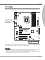
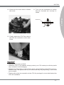
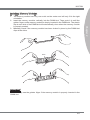
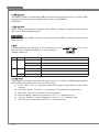
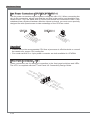
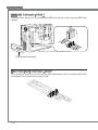
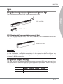
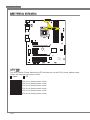
Chapter 1
Getting Started
Thank you for choosing the 7681 v3.2 Series (MS-7681)
ATX mainboard. The series mainboards are based
on Intel® P67 chipsets for optimal system efficiency.
Designed to fit the advanced Intel® LGA1155 processor,
the series deliver a high performance and professional
desktop platform solution.
Getting Started
Mainboard Specifications
Processor Support
■ Intel® Sandy Bridge processor in the LGA1155 package
Chipset
■ Intel® P67 chipset
Memory Support
■ 4 DDR3 DIMMs support DDR3 2133(Over Clocking)/ 1600(Over Clocking)/ 1333/
1066 DRAM (32GB Max)
■ Supports Dual-Channel mode
LAN
■ Supports LAN 10/100/1000 by Realtek® RTL8111E
IEEE 1394
■ 2 IEEE 1394 ports by VIA® VT6308P (pinheader x1, rear panel x1)
Audio
■ Chip integrated by Realtek® ALC892
■ Flexible 8-channel audio with jack sensing
■ Compliant with Azalia 1.0 Spec
SATA
■ 4 SATA 3Gb/s ports (SATA3~6 by Intel® P67 PCH)
■ 4 SATA 6Gb/s ports (SATA1~2 by Intel® P67 PCH, SATA7~8 by Marvell® 9128)
■ 2 eSATA ports (back panel) by JMicron® JMB362
RAID
■ SATA1~6 support Intel® Matrix Storage Technology (AHCI/ RAID 0/ 1/ 5/ 10) by Intel®
P67 PCH
■ SATA7~8 support RAID 0/ 1 mode by Marvell® SE9128
■ 2 eSATA ports support RAID 0/ 1 & JBOD mode by JMicron® JMB362
USB 3.0
■ 2 USB 3.0 rear ports by RENESAS uPD720200AF1-DAP-A
■ 2 USB 3.0 front ports by RENESAS uPD720200AF1-DAP-A
1-2
MS-7681
Connectors/ Ports
Chapter 1
■ Back panel
- 1 PS/2 keyboard/mouse port
- 1 Clear CMOS button
- 1 Coaxial S/PDIF-Out
- 1 Optical S/PDIF-Out
- 1 IEEE 1394 port
- 8 USB 2.0 ports
- 2 USB 3.0 ports
- 2 eSATA ports
- 1 LAN port
- 6 flexible audio ports
■ On-Board
- 1 USB 2.0 connector
- 1 IEEE 1394 connector
- 1 Front Panel Audio connector
- 1 OC switch /LED connector
- 2 USB 3.0 ports
Slots
■ 1 PCIE 2.0 x16 slot (PCI_E2)
■ 1 PCIE 2.0 x8 slot (in x16 slot)(PCI_E5)
■ 3 PCIE 2.0 x1 slots
■ 2 PCI slots, support 3.3V/ 5V PCI bus Interface
Form Factor
■ ATX (30.5cm X 24.5 cm)
Mounting
■ 9 mounting holes
1-3
Getting Started
Mainboard Layout
CPUFAN
Top : mouse orkeyboard
Bottom: USB ports
JPWR2
Clear CMOS
Top:
Coaxial S/PDIF
Buttom:
Optical S/PDIF
SYSFAN4 SYSFAN3
T: 1394 port
M: USB ports
B:e SATA port
Top : USB ports
Bottom: eSATA port
Top: LAN Jack
Bottom: USB 2.0 ports
SYSFAN2
PCI_E1
PCI_E2
BATT
+
PCI_E4
Intel
P67
JBAT1
PCI_E5
J2
PCI1
Fintek
F71889AD
PCI2
JAUD1
USB3
USB4
J1394_1
JUSB1
(MS-7681) ATX Mainboard
1-4
JFP3
JFP3
VIA
VT6308P
PCI_E3
SATA7_8 SATA5_6 SATA3_4 SATA1_2
DIMM1
DIMM2
DIMM3
DIMM4
SYSFAN1
T: Line-In
M: Line-Out
B: Mic
T:RS-Out
M:CS-Out
B:SS-Out
JPWR1
USB 3.0 ports
Chapter 2
Hardware Setup
This chapter provides you with the information about
hardware setup procedures. While performing the installation, be careful in holding the components and following the installation procedures. For some components, if
you install in the wrong orientation, the components will
not work properly.
Use a grounded wrist strap before handling computer
components. Static electricity may damage the components.
Hardware Setup
Quick Components Guide
CPU, p.2-4
JPWR2, p.2-10
CPUFAN, p.2-14
DDR3, p.2-8
Back Panel,
p.2-11
SYSFAN3~4,
p.2-14
JPWR1, p.2-10
JBAT1, p.2-18
SYSFAN2, p.2-14
SYSFAN1, p.2-14
BATT
+
PCIE, p.2-19
SATA1~8, p.2-13
PCI, p.2-19
JFP1, p.2-14
JAUD1, p.2-16
JFP3, p.2-17
USB3/4, p.2-15
J1394_1, p.2-16
JUSB1, p.2-15
2-2
MS-7681
Screw Holes
When you install the mainboard, you have to place the mainboard into the chassis in the
correct direction. The locations of screws holes on the mainboard are shown as below.
Chapter 2
BATT
+
The side has to
toward the rear,
the position for
the I/O shield of
the chassis.
Screw holes
Refer above picture to install standoffs in the appropriate locations on chassis and then
screw through the mainboard screw holes into the standoffs.
Important
• To prevent damage to the mainboard, any contact between the mainboard circuit and
chassis or unnecessary standoffs mounted on the chassis is prohibited.
• Please make sure there are no metal components placed on the mainboard or within
the chassis that may cause short circuit of the mainboard.
2-3
Hardware Setup
CPU (Central Processing Unit)
When you are installing the CPU, make sure to install the cooler to prevent overheating.
If you do not have the CPU cooler, consult your dealer before turning on the computer.
For the latest information about CPU, please visit http://www.msi.com/index.
php?func=cpuform2
Important
Overheating
Overheating will seriously damage the CPU and system. Always make sure the cooling
fan can work properly to protect the CPU from overheating. Make sure that you apply
an even layer of thermal paste (or thermal tape) between the CPU and the heatsink to
enhance heat dissipation.
Replacing the CPU
While replacing the CPU, always turn off the ATX power supply or unplug the power
supply’s power cord from the grounded outlet first to ensure the safety of CPU.
Overclocking
This mainboard is designed to support overclocking. However, please make sure your
components are able to tolerate such abnormal setting, while doing overclocking. Any
attempt to operate beyond product specifications is not recommended. We do not guarantee the damages or risks caused by inadequate operation or beyond product specifications.
Introduction to LGA 1155 CPU
The surface of LGA 1155 CPU. Remember to apply some thermal paste on it for
better heat dispersion.
Alignment Key
Yellow triangle is the
Pin 1 indicator
2-4
Alignment Key
MS-7681
CPU & Cooler Installation
When you are installing the CPU, make sure the CPU has a cooler attached on the top
to prevent overheating. Meanwhile, do not forget to apply some thermal paste on CPU
before installing the heat sink/cooler fan for better heat dispersion.
Follow the steps below to install the CPU & cooler correctly. Wrong installation will
cause the damage of your CPU & mainboard.
2. Open the load level.
3. Lift the load lever up to fully open position.
4. After confirming the CPU direction for correct mating, put down the CPU in the
socket housing frame. Be sure to grasp on the edge of the CPU base. Note that the
alignment keys are matched.
Alignment Key
5. Visually inspect if the CPU is seated well into the socket. If not, take out the CPU
with pure vertical motion and reinstall.
Alignment Key
2-5
Chapter 2
1. The CPU socket has a plastic cap on it to protect the contact from damage. Before
you install CPU, always cover it to protect the socket pin. Romove the cap.
Hardware Setup
6. Engage the load lever while pressing
down lightly onto the load plate.
8. Make sure the four hooks are in porper position before you install the
cooler.
7. Secure the lever near the hook end
under the retention tab.
9. Align the holes on the mainboard with
the heatsink. Push down the cooler
until its four clips get wedged into the
holes of the mainboard.
Important
• Confirm if your CPU cooler is firmly installed before turning on your system.
• Do not touch the CPU socket pins to avoid damaging.
2-6
MS-7681
10. Press the four hooks down to fasten
the cooler.
11. Turn over the mainboard to confirm
that the clip-ends are correctly inserted.
Chapter 2
Mainboard
Hook
12. Finally, attach the CPU Fan cable to
the CPU fan connector on the mainboard.
Important
• Read the CPU status in BIOS.
• Whenever CPU is not installed, always protect your CPU socket pin with the plastic
cap covered to avoid damaging.
• Mainboard photos shown in this section are for demonstration of the CPU/ cooler installation only. The appearance of your mainboard may vary depending on the model
you purchase.
• Please refer to the documentation in the CPU fan package for more details about the
CPU fan installation.
2-7
Hardware Setup
Memory
These DIMM slots are used for installing memory modules. For more information on
compatible components, please visit http://www.msi.com/index.php?func=testreport
DDR3
240-pin, 1.5V
48x2=96 pin
72x2=144 pin
Memory Population Rule
Please refer to the following illustrations for memory population rules.
Dual-Channel mode Population Rule
In Dual-Channel mode, the memory modules can transmit and receive data with two
data bus lines simultaneously. Enabling Dual-Channel mode can enhance the system
performance. The following illustrations explain the population rules for Dual-Channel
mode.
1
DIMM1
DIMM2
DIMM3
DIMM4
2
DIMM1
DIMM2
DIMM3
DIMM4
Installed
Empty
Important
• DDR3 memory modules are not interchangeable with DDR2, and the DDR3 standard
is not backwards compatible. You should always install DDR3 memory modules in
the DDR3 DIMM slots.
• In Dual-Channel mode, make sure that you install memory modules of the same type
and density in different channel DIMM slots.
• To ensure a successful system boot-up, always insert the memory modules into the
DIMM1 first.
• Due to the chipset resource deployment, the system density will only be detected up
to 31+GB (not full 32GB) when each DIMM is installed with a 8GB memory module.
2-8
MS-7681
Installing Memory Modules
1. The memory module has only one notch on the center and will only fit in the right
orientation.
3. Manually check if the memory module has been locked in place by the DIMM slot
clips at the sides.
Notch
Volt
Important
You can barely see the golden finger if the memory module is properly inserted in the
DIMM slot.
2-9
Chapter 2
2. Insert the memory module vertically into the DIMM slot. Then push it in until the
golden finger on the memory module is deeply inserted in the DIMM slot. The plastic
clip at each side of the DIMM slot will automatically close when the memory module
is properly seated.
Hardware Setup
Power Supply
ATX 24-pin Power Connector: JPWR1
This connector allows you to connect an ATX 24-pin power supply. To connect the ATX
24-pin power supply, make sure the plug of the power supply is inserted in the proper
orientation and the pins are aligned. Then push down the power supply firmly into the
connector.
You may use the 20-pin ATX power supply as you like. If you’d like to use the 20-pin
ATX power supply, please plug your power supply along with pin 1 & pin 13.
d
n
u
ro
V
.G 5 V
4
2 3.+ +5 V
d
2 2. 5 s n d
2 1.+ Re ou un d
2 0. Gr ro un #
2 9. G o N d
1 8. Gr -O un
1 7. PS o
1 6. Gr 2V V
1 5. 1 .3
1 4.- +3
1 3.
1
V
.3
3 V
.+ 2 V
2 1 2
1 .+ +1 B OK
11 0. S R d
1 .5V W un
d
9 .P ro
8 .G 5V un
7 .+ ro nd
6 .G 5V u
5 + o V
r
.
4 .G 3.3 3V
.
3
+
.
3
2 .+
1
ATX 8-pin Power Connector: JPWR2
This connector is used to provide the power output to the CPU.
d
n
u d
ro un nd
.G ro u d
4 .G ro un
3 .G ro
2 .G
1
V
2
1 V
.+ 2 V
8 .+1 2 V
7 .+1 12
6 .+
5
Important
Make sure that all the connectors are connected to proper ATX power supplies to ensure stable operation of the mainboard.
2-10
MS-7681
Back Panel
IEEE 1394 Port
Mouse/
Keyboard
Coaxial
S/PDIF-Out
USB 2.0 Port
LAN
RS-Out
Chapter 2
Line-In
Line-Out CS-Out
USB 2.0 Port
Optical
S/PDIF-Out
USB 2.0 Port
eSATA Port
Mic SS-Out
USB 3.0 Port
Clear CMOS Button
▶ Mouse/Keyboard
The standard PS/2® mouse/keyboard DIN connector is for a PS/2® mouse/keyboard.
▶ Clear CMOS Button
There is a CMOS RAM on board that has a power supply from external battery to keep
the system configuration data. With the CMOS RAM, the system can automatically
boot OS every time it is turned on. If you want to clear the system configuration, use
the button to clear data. Press the button to clear the data.
Important
Make sure that you power off the system before clearing CMOS data.
After pressing this button to clear CMOS data in power off (G3) state, the system will
boot automatically.
▶ Coaxial S/PDIF-Out
This S/PDIF (Sony & Philips Digital Interconnect Format) connector is provided for digital audio transmission to external speakers through a coaxial cable.
▶ Optical S/PDIF-Out
This S/PDIF (Sony & Philips Digital Interconnect Format) connector is provided for digital audio transmission to external speakers through an optical fiber cable.
▶ IEEE 1394 Port
The IEEE 1394 port on the back panel provides connection to IEEE 1394 devices.
▶ eSATA Port
The eSATA (External SATA) port is for attaching the eSATA hard drive.
2-11
Hardware Setup
▶ USB 2.0 Port
The USB 2.0 port is for attaching USB devices such as keyboard, mouse, or other USBcompatible devices. Supports data transfer rate up to 480Mbit/s
(Hi-Speed).
▶ USB 3.0 Port
USB 3.0 port is backward-compatible with USB 2.0 devices. It supports data transfer
rate up to 5 Gbit/s (SuperSpeed).
Important
If you want to use a USB 3.0 device, you must use the USB 3.0 cable to connect to the
USB 3.0 port.
▶ LAN
The standard RJ-45 LAN jack is for connection to
the Local Area Network (LAN). You can connect a
network cable to it.
Yellow
Green/ Orange
LED
Color
LED State
Condition
Left
Yellow
Off
LAN link is not established.
On(Steady state)
LAN link is established.
On(brighter & pulsing)
The computer is communicating with another computer on the LAN.
Off
10 Mbit/sec data rate is selected.
On
100 Mbit/sec data rate is selected.
On
1000 Mbit/sec data rate is selected.
Right
Green
Orange
▶ Audio Ports
These audio connectors are used for audio devices. It is easy to differentiate between
audio effects according to the color of audio jacks.
■ Line-In: Blue - Line In, is used for external CD player, tape-player or other audio
devices.
■ Line-Out: Green - Line Out, is a connector for speakers or headphones.
■ Mic: Pink - Mic, is a connector for microphones.
■ RS-Out: Black - Rear-Surround Out in 4/ 5.1/ 7.1 channel mode.
■ CS-Out: Orange - Center/ Subwoofer Out in 5.1/ 7.1 channel mode.
■ SS-Out: Gray - Side-Surround Out 7.1 channel mode.
2-12
MS-7681
Connectors
Serial ATA Connector: SATA1~8
This connector is a high-speed Serial ATA interface port. Each connector can connect
to one Serial ATA device.
Chapter 2
* The MB layout in this figure is for reference only.
SATA1_2
SATA3_4
SATA5_6
SATA1~2 & SATA7~8 (6Gb/s)
SATA3~6 (3Gb/s)
SATA7_8
Important
Please do not fold the Serial ATA cable into a 90-degree angle. Otherwise, data loss
may occur during transmission.
2-13
Hardware Setup
Fan Power Connectors: CPUFAN,SYSFAN1~4
The fan power connectors support system cooling fan with +12V. When connecting the
wire to the connectors, always note that the red wire is the positive and should be connected to the +12V; the black wire is Ground and should be connected to GND. If the
mainboard has a System Hardware Monitor chipset on-board, you must use a specially
designed fan with speed sensor to take advantage of the CPU fan control.
CPUFAN
SYSFAN1~4
d
n
u
ro 2V or
.G 1 s
1 .+ en
2 .S
3
d
n
u
ro 2V or l
.G 1 s o
1 + en tr
.
2 .S on
3 .C
4
Important
• Please refer to the recommended CPU fans at processor’s official website or consult
the vendors for proper CPU cooling fan.
• Fan cooler set with 3 or 4 pins power connector are both available for CPUFAN.
Front Panel Connector: JFP1
These connectors are for electrical connection to the front panel switches and LEDs.
The JFP1 is compliant with Intel® Front Panel I/O Connectivity Design Guide.
P
o
w
e
r
0
in
P o 8.
.+
.N
6
.4 +
.
2
e
ch
w
it
o
w
1
S
P
r
L
E
D
ch
it
w
d
S
e
t
rv e
D
s
E
se e
L
e R
D
.R
D
9
+
H
.
7 .5 .
3 .+
1
2-14
MS-7681
Front USB 2.0 Connector: JUSB1
This connector, compliant with Intel® I/O Connectivity Design Guide, is ideal for connecting high-speed USB interface peripherals such as USB HDD, digital cameras, MP3
players, printers, modems and the like.
Chapter 2
115V
d
C un +
.N o 1
0 r B 11 .G
8 S B
.U S
6 .U C
4 VC
.
2
in
P nd
o u +
.N ro 0
9 .G SB 07 U B
.
S
5 .U CC
3 .V
1
* The MB layout in this figure is for reference only.
USB Bracket (optional)
Important
• Note that the pins of VCC and GND must be connected correctly to avoid possible
damage.
Front USB 3.0 Port: USB3/ USB4
USB 3.0 port is backward-compatible with USB 2.0 devices. Supports data transfer rate
up to 5 Gbit/s (SuperSpeed). It is for medion front connect module.
USB 3.0 connector: USB3/ 4
Important
• If you want to use a USB 3.0 device, you must use the USB 3.0 cable to connect to
the USB 3.0 port.
2-15
Hardware Setup
IEEE1394 Connector: J1394_1
This connector allows you to connect the IEEE1394 device via an optional IEEE1394
bracket.
* The MB layout in this figure is for reference only.
1394 Bracket (optional)
Front Panel Audio Connector: JAUD1
This connector allows you to connect the front panel audio and is compliant with Intel®
Front Panel I/O Connectivity Design Guide.
ct
te
e
D
e
n
o
n
h
io
P
ct
d
e
a
e in et
.H P D
0 o
1 .N IC
d
8 M
n
.
C
u
6
N
o
.
4 Gr
.
2
io
n
L
e D
n
o N
h E R
P _S ne
d
o
a E h
e NS P
.H E d
9 .S ea R
7 .H IC L
5 .M IC
3 .M
1
2-16
MS-7681
OC switch /LED Connector: JFP3
This connector is for electrical connection to the overclocking switch and LED.
l
o
tr
n
co
o T+
+
.N S - D 9 .R T E D
7 .RS C L E
5 O CL
.
3 .O
1
Chapter 2
in
P
o +.N W
0 S W
1 W S +
.P W C 8 .P .O C
6 4 .O
2
2-17
Hardware Setup
Jumpers
Clear CMOS Jumper: JBAT1
There is a CMOS RAM on board with an external battery power supply to preserve the
system configuration data. With the CMOS RAM, the system can automatically boot OS
every time it is turned on. If you want to clear the system configuration, set the jumper
to clear data.
1
JBAT1
1
Keep Data
1
Clear Data
Important
You can clear CMOS by shorting 2-3 pin while the system is off. Then return to 12 pin position. Avoid clearing the CMOS while the system is on; it will damage the
mainboard.
2-18
MS-7681
Slots
PCIE (Peripheral Component Interconnect Express) Slot
The PCIE slot supports the PCIE interface expansion card.
Chapter 2
PCIE x16 Slot
PCIE x1 Slot
PCI (Peripheral Component Interconnect) Slot
The PCI slot supports LAN card, SCSI card, USB card, and other add-on cards that
comply with PCI specifications.
32-bit PCI Slot
Important
When adding or removing expansion cards, make sure that you unplug the power supply first. Meanwhile, read the documentation for the expansion card to configure any
necessary hardware or software settings for the expansion card, such as jumpers,
switches or BIOS configuration.
PCI Interrupt Request Routing
The IRQ, acronym of interrupt request line and pronounced I-R-Q, are hardware lines
over which devices can send interrupt signals to the microprocessor. The PCI IRQ pins
are typically connected to the PCI bus pins as follows:
Order1
Order2
Order3
Order4
PCI Slot1
INT A#
INT B#
INT C#
INT D#
PCI Slot2
INT B#
INT C#
INT D#
INT A#
2-19
Hardware Setup
LED Status Indicators
BATT
+
APS LEDs
APS LED
The APS (Active Phase Switching) LED indicate the current CPU power phase mode.
Follow the instructions below to read.
: Lights
: Off
CPU is in 1 phase power mode.
CPU is in 2 phase power mode.
CPU is in 3 phase power mode.
CPU is in 4 phase power mode.
CPU is in 5 phase power mode.
CPU is in 6 phase power mode.
2-20