1
DENON
AV SURROUND RECEIVER
AVR-1909
Owner's Manual
Manuel de l'Utilisateur
ENGLISH
FRANCAIS
SAFETY INSTRUCTIONS
o SAFETY PRECAUTIONS
Read Instructions - All the safety and operating instructions should be read
before the product is operated.
2. Retain Instructions - The safety and operating instructions should be
retained for future reference.
Heed Warnings - All warnings on the product and in the operating
3
instructions should be adhered to.
4. Follow Instructions - All operating and use instructions should be followed.
5. Cleaning - Unplug this product from the wall outlet before cleaning. Do not
use liquid cleaners or aerosol cleaners.
6. Attachments - Do not use attachments not recommended by the product
manufacturer as they may cause hazards.
7. Water and Moisture - Do not use this product near water - for example,
near a bath tub, wash bowl, kitchen sink, or laundry tub; in a wet basement;
or near a swimming pool; and the like.
8. Accessories - Do not place this product on an unstable cart, stand, tripod,
bracket, or table. The product may fall, causing serious injury to a child or
adult, and serious damage to the product. Use only with a cart, stand,
tripod, bracket, or table recommended by the manufacturer, or sold with the
product. Any mounting of the product should
follow the manufacturer's instructions, and should
use a mounting accessory recommended by the
manufacturer.
9. A product and cart combination should be moved
with care. Quick stops, excessive force, and
uneven surfaces may cause the product and cart
combination to overturn.
10. Ventilation - Slots and openings in the cabinet are provided for ventilation
and to ensure reliable operation of the product and to protect it from
overheating, and these openings must not be blocked or covered. The
openings should never be blocked by placing the product on a bed, sofa,
rug, or other similar surface. This product should not be placed in a built-in
installation such as a bookcase or rack unless proper ventilation is provided
or the manufacturer's instructions have been adhered to.
11. Power Sources - This product should be operated only from the type of
power source indicated on the marking label. If you are not sure of the type
of power supply to your home, consult your product dealer or local power
company. For products intended to operate from battery power, or other
sources, refer to the operating instructions.
12. Grounding or Polarization - This product may be equipped with a polarized
alternating-current line plug (a plug having one blade wider than the other).
This plug will fit into the power outlet only one way. This is a safety feature.
If you are unable to insert the plug fully into the outlet, try reversing the
plug. If the plug should still fail to fit, contact your electrician to replace your
obsolete outlet. Do not defeat the safety purpose of the polarized plug.
1.
CAUTION:
TO REDUCE THE RISK OF ELECTRIC SHOCK, DO NOT REMOVE
COVER (OR BACK). NO USER-SERVICEABLE PARTS INSIDE.
REFER SERVICING TO QUALIFIED SERVICE PERSONNEL.
The lightning flash with arrowhead symbol. within an equilateral
triangle, is intended to alert the user to the presence of
uninsulated "dangerous voltage" within the product's enclosure
that may be of sufficient magnitude to constitute a risk of electric
shock to persons.
The exclamation point within an equilateral triangle is intended
to alert the user to the presence of important operating
and maintenance Iservicing) instructions in the literature
accompanying the appliance.
WARNING:
TO REDUCE THE RISK OF FIRE OR ELECTRIC SHOCK, DO NOT
EXPOSE THIS APPLIANCE TO RAIN OR MOISTURE.
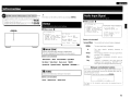
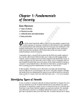
fiGURE A
EXAMPLE OF ANTENNA GROUNDING
AS PER NATIONAL
ELECTRICAL CODE
ANTENNA
LEAD IN
WIRE
ANTENNA
DISCHARGE UNIT
(NEe SECTION 810·20)
_ _ POWER SERVICE GROUNDING
elECTRODE SYSTEM
NEe - NATIONAL ELECTRICAL CODe (NEe ART 250. PART H)
I
13. Power-Cord Protection - Power-supply cords should be routed so that they
are not likely to be walked on or pinched by items placed upon or against
them, paying particular attention to cords at plugs, convenience receptacles,
and the point where they eXit from the product
14. Outdoor Antenna Grounding - If an outside antenna or cable system is
connected to the product, be sure the antenna or cable system is grounded
so as to provide some protection against voltage surges and built-up static
charges. Article 810 of the National Electrical Code, ANSI/NFPA 70. provides
information with regard to proper grounding of the mast and supporting
structure, grounding of the lead-in wire to an antenna discharge unit, size
of grounding conductors, location of antenna-discharge unit, connection to
grounding electrodes, and requirements for the grounding electrode. See
Figure A.
15. Lightning - For added protection for this product during a lightning storm,
or when it is left unattended and unused for long periods of time, unplug it
from the wall outlet and disconnect the antenna or cable system. This will
prevent damage to the product due to lightning and power-line surges.
16. Power Lines - An outside antenna system should not be located in the
vicinity of overhead power lines or other electric light or power circuits, or
where it can fall into such power lines or circuits. When installing an outside
antenna system, extreme care should be taken to keep from touching such
power lines or circuits as contact with them might be fatal.
17. Overloading - Do not overload wall outlets, extension cords, or Integral
convenience receptacles as this can result in a risk of fire or electric shock.
18. Object and Liquid Entry - Never push objects of any kind into this product
through openings as they may touch dangerous voltage points or short-out
parts that could result in a fire or electric shock. Never spill liquid of any kind
on the product.
19. Servicing - Do not attempt to service this product yourself as opening or
removing covers may expose you to dangerous voltage or other hazards.
Refer all servicing to qualified service personnel.
20. Damage Requiring Service - Unplug this product from the wall outlet
and refer servicing to qualified service personnel under the following
conditions:
a) When the power-supply cord or plug is damaged,
b) If liquid has been spilled, or objects have fallen into the product,
c) If the product has been exposed to rain or water,
d) If the product does not operate normally by following the operating
instructions. Adjust only those controls that are covered by the operating
instructions as an improper adjustment of other controls may result in
damage and will often require extensive work by a qualified technician to
restore the product to its normal operation,
e) If the product has been dropped or damaged in any way, and
f) When the product exhibits a distinct change in performance - this
indicates a need for service.
21. Replacement Parts - When replacement parts are required, be sure the
service technician has used replacement parts specified by the manufacturer
or have the same characteristics as the original part. Unauthorized
substitutions may result in fire, electric shock. or other hazards.
22. Safety Check - Upon completion of any service or repairs to this product,
ask the service technician to perform safety checks to determine that the
product is in proper operating condition.
23, Wall or Ceiling Mounting - The product should be mounted to a wall or
ceiling only as recommended by the manufacturer.
24, Heat - The product should be situated away from heat sources such as
radiators. heat registers, stoves, or other products (including amplifiersl that
produce heat.
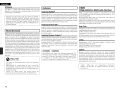
FRANCAIS
FCC INFORMATION (For US customers)
ENGLISH
o NOTE ON USE I OBSERVATIONS RELATIVES A L'UTILISATION
1. PRODUCT
This product complies with Part 15 of the FCC Rules. Operation is subject to the following two conditions: (1) this
product may not cause harmful interference. and (2) this product must accept any interference received, including
interference that may cause undesired operation.
2. IMPORTANT NOTICE: DO NOT MODIFY THIS PRODUCT
This product, when installed as indicated in the instructions contained in this manual, meets FCC requirements.
Modification not expressly approved by DENON may void your authority, granted by the FCC, to use the product.
3. NOTE
This product has been tested and found to comply with the limits for a Class B digital device. pursuant to Part 15
of the FCC Rules. These limits are designed to provide reasonable protection against harmful interference in a
residential installation.
This product generates, uses and can radiate radio frequency energy and, if not installed and used in accordance
with the instructions, may cause harmful interference to radio communications. However, there is no guarantee
that interference will not occur in a particular installation. If this product does cause harmful interference to radio or
television reception, which can be determined by turning the product OFF and ON, the user is encouraged to try to
correct the interference by one or more of the following measures:
• Reorient or relocate the receiving antenna.
• Increase the separation between the equipment and receiver.
• Connect the product into an outlet on a cirCUit different from that to which the receiver is connected.
• Consult the local retailer authorized to distribute this type of product or an experienced radio!TV technician for
help.
• Keep the unit free from mOisture, water,
and dust.
• Proteger rappareil contre I'humidit€!. I'eau
et la poussiere.
high temperatures.
Allow for sufficient heat dispersion when
installed in a rae
• Eviler des temperatures elevees.
Tanir compte d'une dispersion de chaleur
suffisante lars de I'installation sur une
etagere.
• Do not let foreign obJecls into the unit.
• Ne pas laisser des objets etrangers dans
I'apparell.
• AVOid
1----------------1
This Class B digital apparatus complies with Canadian ICES-003.
Cet appareil numerique de la classe Best con forme a la norme NMB-003 du Canada.
• Unplug the power cord when not usmg the
unit for long periods of time.
• Debrancher Ie cordon d'alimematlon
lorsque I'appareil n'est pas utilise pendant
de longues periodes.
• Do not let insecticides. benzene, and
thinner come In contact with the unit.
• Ne pas mettre en contact des insecticides.
du benzene et un dtluant avec I'apparei!.
-=,,)\\~I\
• Handle the power cord carefully.
Hold the plug when unplugging the cord.
• Manipuler Ie cordon d'alimemation avec
precaution.
Tenir la prise lars du debranchement du
U~.::i\W
• (For apparatuses with ventilation holes)
cordon.
• Do not obstruct the ventilation holes.
• Ne pas obstruer les traus d'aeration.
• Never disassemble or modify the unit in
any way.
• Ne jamais demonter au modifier I'appareil
d'une maniere au d'une autre.
II
ENGLISH
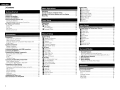
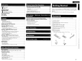
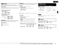
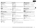
o Contents
Getting Started
···· .... ·····2
Accessories············· .
............... ·3
Cautions on Handling·····
Cautions on Installation··
.
..·3
About the Remote Control Unit·
··3
................. .. .. ·3
Inserting the Batteries·
.
· .. ·3
Operating Range of the Remote Control Unit
Part Names and Functions· .
·4
Front Panel
.
..·4
.
·.. ·5
Display·····
.
................ ··6
Rear Panel
··· .... ·7
Remote Control Unit
Connections
Preparations .. ·
..
·8
8
Cables Used for Connections· .
.. ·····9
Video Conversion Function
On-Screen Display for Component Video Outputs and
.. ·· .. 9
HDMIOutput
Speaker Connections "
···10
..·10
Speaker Installation .
Speaker Connections
..
.
.. .. ·10
·····12
Connecting Equipment with HDMI connectors
Connecting the Monitor··
.
.. .. ·13
·.. ··· .. ·13
Connecting the Playback Components
13
Blu-ray Disc player / DVD player
..14
CD Player .....
..14
iPod® ..
TV/CABLE Tuner
.
..
·····15
..15
Connecting the Recording Components
.
Video Cassette Recorder
..
·· .. ·15
.... ·16
CD Recorder / M D Recorder / Tape Deck·
·····16
Connections to Other Devices··
Video Camera / Game Console
.
16
Component with Multi-channel Output connectors
·····17
XM connector .
·····17
18
SIRIUS connector·
19
Antenna terminals
Multi-zone
.
····20
·20
External Controller···· ·············
............... ·21
Connecting the Power Cord·
.
····21
Once Connections are Completed
1
Operations··
.. ··· ·.. ··..·····22
Example of Display of Default Values·· .... ·· .. ·
·....
..... 22
Examples of On-screen Display and Front Display
·.. ··23
Menu Map··..
.
24
·35
·35
.. ···35
·.. ·36
·36
·36
·36
·36
····37
··· .. 37
..
m
m
Auto Setup
Preparations .
..
Auto Setup
D Start Menu .. ·
Error Messages···
fJ Parameter Check
···25
·····26
...... 26
·28
...... 29
Manual Setup
Speaker Setup·
D Speaker Configuration·
fJ Subwoofer Setup
II Distance··
lEI Channel Level
II Crossover Frequency
Front Speaker Setup
HDMI Setup·
D Color Space
fJ RGB Range·
II Auto Lipsync
lEI HDMI Audio Out··
II HDMI Control .... ·· ...... ·· ..
Power Off Control
Audio Setup
.
D EXT. IN Subwoofer Level
fJ 2ch Direct/Stereo·
II Dolby Digital Setup
lEI Auto Surround Mode· .
II EQ Preset·
ZONE2 Setup
D Level Lch
fJ Level Rch
II Volume Limit
.
lEI Power On Level·
II Mute Level
Option Setup··
Amp Assign
fJ Volume Control··
II Source Delete .......
lEI On-Screen Display
II Quick Select Name·
Remote ID Setup·
B 2Way Remote
II Display··
Setup Lock
a
Menu Operations
m
····29
......... ··29
.. ·30
30
···31
·····31
.. .. 31
···32
··· .. 32
...............
..
.
····32
·........··....·32
·32
··32
·· .... 32
·33
.... ·33
m
.
.
.. .. ·33
33
..·33
·34
.. ··34
.. ·34
···34
..·35
·····35
·35
Input Setup
38
Settings Related to Playing Input Sources·· .. ·
Auto Preset···
.
fJ Preset Skip ..
II Preset Name
lEI Video·
.
II Input Mode .
Rename·····
.
B Source Level
II Assign················ .. ···
iPod
.
Oil Antenna Aiming
Parenral Lock
a
m
·39
. ·· .. ·39
·39
39
........ ·39
··41
····41
·41
m
.... ·42
··· .. ·42
m
43
.. 43
Surround Modes
CD Standard Playback·..
CV
®
CD
...... 44
Surround Playback of 2-channel Sources
····44
Playing Multi-ehannel Sources (Dolby Digital. DTS. etc.) .. ········45
DSP Simulation Playback
··45
Direct Playback·····
···45
Stereo Playback· .. ·.. ···
.... 45
Playback in the PURE DIRECT Mode .. ···
·······46
Parameter
Adjusting the parameters
Surround Parameter··
Surround Parameter
Tone
..
Audyssey Settings
RESTORER··················
Night Mode
Audio Delay··
..
.
···46
.. ····47
··47
·.. ·.. ·49
·49
..·51
·····51
51
ENGLISH
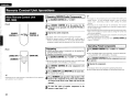
Remote Control Unit Operations
Information
Status
.
MAIN ZONE
II ZONE2
.
Audio Input Signal··········
HOMI Information·· . .
HDMI Signal Information
II HDMI Monitor Information
Auto Surround Mode
Quick Select·
.
Preset Station
o
o
.
.
.
···52
···52
·52
52
··53
53
·53
53
··53
·53
Playback
Preparations·
··54
Turning the Power On·
·54
Selecting the Input S o u r c e · · : · · · · · · 54
Operations During Playback
... ····54
Playing Video and Audio E q u i p m e n t · · · · · · 5 5
Basic Operation···
·······55
Listening to FMIAM B r o a d c a s t s · · · · · · · 55
Basic Operation
·······55
Presetting Radio Stations (Preset Memory)
····55
Listening to Preset Stations
·56
·······56
Listening to XM Satellite Radio Programs
Basic Operation
······56
·56
Checking the XM Signal Strength and Radio ID·
Presetting Radio Stations (Preset Memory)
57
Listening to Preset Stations··
·····57
Searching Categories
.
·······57
57
Listening to SIRIUS Satellite Radio Programs·
Basic Operation··
·······58
····58
Checking the SIRIUS Signal Strength and Radio ID
Presetting Radio Stations (Preset Memory)··
··········58
Listening to Preset Stations··
..
... ·······58
Searching Categories
. ····59
Parental Lock
······59
··59
iPod® Playback··
Basic Operation··
·59
······················60
Listening to Music·
Viewing Still Pictures or Videos on the iPod
·60
Main Remote Control Unit {RC-1099) .. ·· ........ ·.... ·
Operating DENON Audio Components
Presetting
· .. ·
.
Operating Preset Components
Punch Through Function
..
Sub Remote Control Unit (RC-1107)
...... 65
.... ·65
·65
.. ·65
.. 68
.. 68
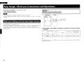
Amp Assign I Multi-zone Connections and
Operations
Multi-zone Settings with the Amp Assign Function
69
Multi-zone Settings and Operations with Zone Output ..
71
Multi-zone Operations..
...... ..........
·72
·.. ··72
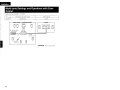
Turning the Power On and Off·
..
Selecting the Input Source
···72
.... ·· .. 72
Adjusting the Volume· .
Turning off the Sound Temporarily··
········72
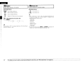
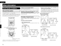
Getting Started
Thank you for purchasing this DENON product. To ensure proper
operation, please read this owner's manual carefully before using the
product.
After reading them, be sure to keep them for future reference.
Accessories
Check that the following parts are supplied with the product.
CD Owner's manual
Troubleshooting
73
82
.
...... 1
@ Getting Started
..
(1) Warranty (for North America model only)
® Service station list
® Main remote control (RC-1 099)
® R6/AA batteries (for RC-1099)
....... 1
.
1
.
1
....... 1
..
.
.
Sub remote control (RC-11 07) ..
® R03/AAA batteries (for RC-11 07)
® FM indoor antenna
@ AM loop antenna
.
@ Setup microphone
(DM-A409, Cord length: Approx. 25 ft /7.6 m) .
(j)
Other Information
.
2
.1
...... 2
.... 1
...... 1
.. .... 1
o
Specifications
"~
86
o
:.1
List of preset codes
End of thiS manual
Other Operations and Functions
Other Operations··
61
Recording on an External Equipment (REC OUT mode)
·····61
Convenient Functions···
·62
HDMI Control Function
..·62
Channel Level
···......
.
63
Fader Function..
..
63
Quick Select Function .. ·
·64
Personal Memory Plus Function
·
·.. ·.. ··· · ·64
Last Function Memory
·· .. ·· .. ·· .. ·.. · ···
··
·.. ·· .. ·.. ··
··64
Backup Memory.. ····
· ·
··· .. ······ .. ·.. ·· .. ·· .. ·.. ····· .. ···64
Resetting the Microprocessor
64
I
2
ENGLISH
I
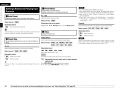
Cautions on Handling
• Before turning the power switch on
Check once again that all connections are correct and that there are
no problems with the connection cables.
• Power is supplied to some of the circuitry even when the unit is
set to the standby mode. When traveling or leaving home for long
periods of time, be sure to unplug the power cord from the power
outlet.
• About condensation
If there is a major difference in temperature between the inside of
the unit and the surroundings, condensation (dew) may form on
the operating parts inside the unit, causing the unit not to operate
properly.
If this happens, let the unit sit for an hour or two with the power
turned off and wait until there is little difference in temperature
before using the unit.
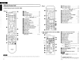
About the Remote Control Unit
In addition to the AVR-1909, the included main remote control unit
(RC-l099) can also be used to operate the equipment listed below.
CD DENON system components
CV Non-DENON system components
• By setting the preset memory (~page 65 - 67)
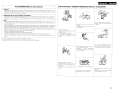
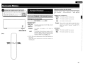
Inserting the Batteries
CD
Lift the clasp and remove the rear lid.
(RC-ll07)
• Cautions on using mobile phones
Using a mobile phone near this unit may result in noise. If so, move
the mobile phone away from this unit when it is in use.
• Moving the unit
Turn off the power and unplug the power cord from the power
outlet.
Next, disconnect the connection cables to other system units before
moving the unit
CV
.N·U·
• Replace the batteries with new ones if the set does not operate
even when the remote control unit is operated close to the unit.
• The supplied batteries are only for verifying operation.
• When inserting the batteries, be sure to do so in the proper direction,
following the "Ej;)" and "8" marks in the battery compartment.
• To prevent damage or leakage of battery fluid:
• Do not use a new battery together with an old one.
• Do not use two different types of batteries.
• Do not attempt to charge dry batteries.
• Do not short-circuit, disassemble, heat or dispose of batteries in
flames.
• If the battery fluid should leak, carefully wipe the fluid off the inside
of the battery compartment and insert new batteries.
• Remove the batteries from the remote control unit if it will not be in
use for long periods.
• When replacing the batteries, have the new batteries ready and
insert them as quickly as possible .
Operating Range of the Remote Control
Unit
Load the two batteries properly as indicated by the marks in the
battery compartment
Point the remote control unit at the remote sensor when operating it.
(RC-ll07)
R03/AAA
• Note that the illustrations in these instructions may differ from the
actual unit for explanation purposes.
Cautions on Installation
Note:
For proper heat dispersal, do not install this unit in a confined
space, such as a bookcase or similar enclosure.
®
Put the rear cover back on.
Approx. 23 feet / 7 m
(RC-l099)
.Neii.
The set may function improperly or the remote control unit may not
operate if the remote control sensor is exposed to direct sunlight,
strong artificial light from an inverter type fluorescent lamp or infrared
light
3
ENGLISH
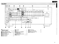
Part Names and Functions
~Cursor buttons (ll. \7)
·····122}
~ MASTER VOLUME control knob
..... (54)
For buttons not explained here, see the page indicated in parentheses ( ).
4D AUDYSSEY DYNAMIC VOLUME
II Front Panel
f) HD AUDIO indicator .. ·.... ·
«i) Master volume indicator
indicator..
.
..
El DYNAMIC VOLUME button
* About Dynamic Volume
... (50)
·····(45)
~Display
WRemote control sensor ....
....... (72)
~SOURCE SELECT k n o b ·
·······(54)
@lSOURCE button· .... ·....
~STATUS button
~ DIMMER button
~ RESTORER button
~ BAND button··········· .. ··
~ SHIFT button
o Power operation button
~ SETUP MIC jack··
(ON/STANDBY) .
8
..... (54)
Power i n d i c a t o r · · · · · (54)
C) Power switch (.-ON .OFF)
(54)
8Headphones jack (PHONES)
(54)
01NPUT MODE b u t t o n ·
o SPEAKERS button
(17, 41)
(31, 54)
8 ZONE2 ON/OFF button····
8 QUICK SELECT buttons···
0v. AUX INPUT connectors
(72)
(64)
... (3)
~ ZONE2/REC SELECT button
·(54)
(52,56)
········ .. (37)
(51)
...... (551
.. (551
@) PRESET buttons·
..... (55)
€il TUNING buttons
..... (55)
G) MULTEQ button·
..... (49)
*
(50)
Audyssey Dynamic Volume™ solves the problem
of large variations in volume level between
television programs. commercials. and between
the soft and loud passages of movies.
Audyssey Dynamic EOTM is integrated into
Dynamic Volume so that as the playback volume
is adjusted automatically, the perceived bass
response, tonal balance, surround impression.
and dialog clarity remain the same .
About Dynamic EQ
Audyssey Dynamic EO solves the problem of
deteriorating sound quality as volume is decreased
by taking into account human perception and
room acoustics. Audyssey Dynamic EO works in
tandem with Audyssey MultEO® to provide wellbalanced sound for every listener at any volume
level.
@)VIDEO SELECT b u t t o n · · · ·
(39)
....... (25)
41 MENU button
.......... (22)
~ RETURN button
.
~ SELECT/ENTER knob·· .
..
(22)
.
(22)
#
• The SELECT/ENTER knob on the main unit
operates in the same way as the cursor <l and C>
buttons on the remote control unit.
SElECTfEIIITER
Remove the cap covering the terminals when
you want to use them.
:0:
(
)
• The control functions in the same way as the
cursor <l button when turned counterclockwise.
as the cursor C> button when turned clockwise.
• The control functions in the same way as the
ENTER button when pressed the knob.
4
I
::
ENGLISH
Display
I
iiiii:::::i=~=1
=J) .
=::....=====.:::::::::::..::::::::::::::
::::::::::I·-I-·~
o Input signal indicators
4D NIGHT indicator
81nput signal channel indicators
These light when digital signals are input.
(B RESTORER indicator
•
8
Information display
The input source name, surround mode, setting
values and other information are displayed
here.
Output signal channel indicators
o Front speaker indicator
These light according to the settings of the front
A and B speakers.
(1) ZONE2 output indicator
This lights when the power for the ZONE2 is
turned on.
o Master volume indicator
(;) AUDYSSEY MULTEO indicator
This lights when the MultEQ is selected.
01nput mode indicators
tIi> Recording output source indicator
This lights when the REC OUT mode is
selected.
5
This lights when the night mode is selected.
This lights when the RESTORER mode is
selected.
~ HDMI indicator
This lights
connections.
when
playing
using
HDMI
4J) Decoder indicators
These light when the respective decoders are
operating.
4i)Tuner reception mode indicators
This lights according to the reception conditions
when the input source is set to "TUNER".
-AUTO
This lights when in the auto tuning mode.
- STEREO
In the FM mode, this lights when receiving
analog stereo broadcasts.
-TUNED
This lights when the broadcast is properly tuned
in.
ENGLISH
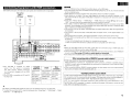
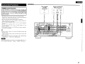
Rear Panel,
l~ ~ ~; jl,-~ -~-3~v-':A-~'-;'-.I-~-:=-O-N'T-OA-~-4+~-:-: -:-:rl-tg-~-.:-.:~4_-1.~_ _~ _~ ]
0 I
••_••
~I _-, S:- ~- :- s-
_ _.-.-U--FA-O-NT-----
----~-~
n
. ---..-SU-AA-O-UN-O-.--.-S-UA-A-BA-CK-IA-M-P-AS-SIG-N-.-.
. .• .•·••. ©
.•. ·•.. • . . • .•. .•.•.
RIi
..
W-
,
_,-
I
AC 120V
60Hz
I
(J[J:.
'""
"r
~ o~.o··.• • (I.~· O·~·~. .O
. ··O··.rI..O·'ii··O FAONT:O.A:l:=::~ ~~~:~:NO·:=::~ :~ApAA::I~~.6~16Q
•
J JDllj·.
",'
1IlliI[8
()
I
,P:cRi
T 2
I
I
TVI
CBL
(,Pod)
TAPE
:.......
DIGITAL
(ASSIGNABLEI
FA
SWlTCHED TOTAl 120W(1A.) MAX
i
i
REMDTECONTROl
{@;"'@)
I,:"~ i~.~~ CJ
ROOM TO ROOM
•••••••••• laiii ~ ••
(J[J
l!lIl
•
--C,I~J
(1) AC OUTLETS
.VIDEO I S-VIDEO connectors
(13 - 16)
4D> Speaker terminals (SPEAKERS)
.Analog audio connectors (AUDIO)
(13 - 16)
4D FMIAM antenna terminals
o
REMOTE CONTROL jacks
.PRE OUT connector
•
.
ZONE2 connectors················
(17)
(20)
.
[.I~~
........ (21)
.
o
GEXT.IN connectors··· .
...
o
OOigital audio connectors
(OPTICAL I COAXIAL)---- (13 - 15, 18)
(10)
Power cord
(TUNER ANTENNA)
.
... (21)
........ (10)
~RF/RC 2 WAY j a c k · ·
49 XM connector (SAT TU2)
("')
0
~
£.
' . :.:
i11
JJ
,I 3"
I
0
I :;:
'1
TAPEI
-c
f-.--2.-
~.. ~LO
~
----+-..------ ID CO-R
VCR O.~.~
OVO
VCR ..~
HOP ..~
CO-AI ..~~
~
SW ..~
SA ..~
SBR .. S~.BWDDFER.(~·~0.z·".~E20
..
~:
IlfctRi
2
"
I ¥
gI.
~.
'y
I
'Jl
II <:~
·.b.·.··.··
.•.••..••.••.
• c::=:J
~
I
ooc~coiTTul~sIRlu.,.ss.lr. @
. 0.. /RC2J
. ii"iJ'i~ Irt,1 o
.• .• •. • ~.· .©·~.· .· ·. · ~·.a.c
. ·~ ~©.~~~©~.. ,~
.• .• ·. .©l•.c~.·.• . •. ~.• . •. .• .·
•..•©
•.~~i..• . .•.•·.•.~
•. •. ~
.• ~ ;.•. • . • •. •~
. .•~.~::.• .~•.•·. ·.) '.~ ·. ·. ·.~:.'.•
AC OUTLETS
Ii .• • •.~• • • ~• . ~ ~ /~ .~ .• .• .~ .•.• ~.• i~:
~~~-1 (0 I.~. @J @J @J!~ ~ ~.I ~:/i//i/iii
tc··········c·········
=1
...................
1~~f-2!~ ~ vl~TPd~.e.g i!'colv7DEO!lEI' EXT~i~
...~. ~ . ~
..••.~...~.• ~....~.~ ~=
IN " ,.,
SPEAKER IMPEDANCE
1>\:;:;1 VIDE~'.IlGI\,"l.mo."'\VIm'~'llli~:
~
I
I ::.'.
... ···(20)
. (17)
~ SIRIUS connector (SAT TU 1)
...... (18)
48 DOCK CONTROL jack···········
... (14)
(191
~COMPONENT VIDEO connectors
(13,15)
~HOMI connectors
····(12, 13, 15)
(20)
6
ENGLISH
I
Remote Control Unit
o
o ZONE2 power buttons
8 Source select buttons··
* :To select "SIRIUS",
[ Rear]
Main Remote Control Unit (RC-1099)
o Indicator
,"-·zONE1--", '---tiAiN----~
~OFFON::OFFON~
.
f) Power buttons
•
----.--m:Q
8' 'Q 0!~
........... .. =~_~:_::::: ... J
.. (65)
.
QUICK SELECT buttons
.~.JCb
.. (54)
...... (641
o Source select buttons··
:
TV/CBL
select "SIRIUS", "XM" as the input
source, use the SAT TU1/2 button.
l.gJ.,GS cGjEi
•
~:
iPod
•
Video select button (V.SEL)
o Tuner system buttons·················· .. ·.. ... (551
o Test tone button (TEST)
o MAIN ZONE power buttons (MAIN)
8 Surround mode buttons
(45, 46)
o Amp menu button (A. MENU)
o Input mode button (INPUT)
(17, 41)
(22)
SATTUlI2:
:0G3t+*
System buttons··
(60)
AUDIO DELAY button··
(51)
Cursor buttons (f:,. \7 <3 C»
(571
~, rCr··5·····a~1
ID RETURN button
(50)
(3
~ Cursor buttons (f:,. \7<3
DYNAMIC VOLUME button
Ci)RESTORER button·····
.
C!>SOURCE CONTROL switches·
(22,65)
(51)
48 Remote control signal transmitter
48 Master volume control buttons
(54)
~ MUTING button
(54)
~ NIGHT button
(51 )
4Gl MULTEQ button·························
(49)
TOPMENU
(59, 63)
LQ...Q
~
allr
Enter button (ENT)
(22)
.
(22)
C»
(22)
IIII .
SfTUP:'0'8*-0
;
IIII
4. MfNU : __
INPUT
AUDIO
Q !0~: ~~~IIII
(3)
4D Channel select (CH SEL) /
ENTER button··
o
MODE
(39)
(72)
&-+ffi--i
lill
"XM" as the input
source, use the SAT TU1/2 button.
(31)
VCR:
GJ 0:
iG]
(54)
*: To
o
o
8
o
Dva
GJ!
(72)
(54)
ENT
I
o..!'ll"""""'U[~111
:0:~
MEMORY
TEST
I
III'
o
: RETURN
III
~
Sub remote control unit for ZONE2
(RC-1107)
O~--..,
o Remote control signal transmitter
8
Zone power off button (OFF)
•
CHANNEL buttons
o TUNING buttons
o System buttons
o REPEAT button··
8
(3)
(68)
.
.
........ ···
(68)
.. (68)
(68)
.
(68)
RANDOM button·························
(68)
o Zone power on button (ON)·
o Source select buttons···
(68)
(68)
*1 : To select "SIRIUS" asthe input source, use
the SAT TUl button.
*2: To select "XM" as the input source, use
the SATTU2 button.
DENON
~ Volume control buttons (VOLUME)
(68)
ID Muting button (MUTE)
(68)
~ SHIFT button
.. (68)
Gl FAVORITES DIRECT PLAY button
(68)
.~[.u.
• N.Ji.
If buttons on the front or rear are pressed strongly. the button on the opposite side will be activated too.
7
The DTU and PHONO buttons cannot be used .
#"
The FAVORITES DIRECT PLAY button can function
when the control dock for iPod ASD-3N/3W is
used.
ENGLISH
I
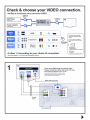
, Connections
Connections for all compatible audio and video signal formats
are described in this owner's manual. Please select the types of
connections suited for the equipment you are connecting.
With some types of connections, certain settings must be made
on the AVR-1909. For details, refer to the instructions for the
respective connection items below.
-N·na
• Do not plug in the power cord until all connections have been
completed.
• When making connections, also refer to the operating instructions of
the other components.
• Be sure to connect the left and right channels properly (left with left,
right with right).
• Do not bundle power cords together with connection cables. Doing
so can result in humming or noise.
Preparations
I
II Cables Used for Connections
Select the cables according to the equipment being connected.
Audio cables
Video cables
Component video connections
Coaxial digital connections
(Orange)
e
~
0
Coaxial digital (75 O/ohms pin-plug) cable
(Green)
~ ~
(Blue) ~
(Red)
~
~ll!
.o:i-J
C)---------lClP
[£J]
S-Video connections
Optical cable
00----00
Analog connections (stereo)
(White)
e
(Red) ~
~e
~e
S-Video cable
Video connections
(Yellow)
Stereo pin-plug cable
e
cj[]::=------:::[]IP
e 9[J:::------:DIP e
75 O/ohms pin-plug video cable
Analog connections (monaural, for subwoofer)
(Black)
G (Y)
G (Ps/Cs)
~ G (PR/CR)
_Ill
Component video cable
Optical digital connections
m
~
e
Pin-plug cable
Audio and video cables
HOMI connections
Speaker connections
:
)iiiiiiiiiiiiiii~(
+
19-pin HDMI cable
Speaker cables
Signal direction
Audio signal:
~ Output
llnput
1
Input
T
Output
Video signal
Output
t
Input
1
Input
T
Output
8
ENGLISH
I
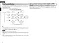
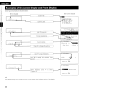
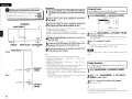
• This function automatically converts various formats of video signals input to the AVR-1909 into the
format used to output the video signals from the AVR-1909 to a monitor.
• The AVR-1909's video input/output circuitry is compatible with the following four types of video signals:
Digital video signals: HOMI
Analog video signals: Component video, S-Video and Video
[Flow of video signals inside the AVR-1909]
High picture
quality playback
1+I
1=
'=----.===-'
l§l
Y
------.:o-'J+
'=-[=
I
'=
J+
==:J+
1
'--I,=-=
l>
~
HOMI connector
pwc.
PNCR
~~~
/
/
/
::" / / A
Component video
connectors
\')",,71
/
/",0 """
0connecto~
?/~).()
S-Video
HOM I connector
Y
PWC. PNCR
~~~
Component video
connectors
@)
.0
Monitor
;"",,\ S-Video connector
~ V .
~
Video connector
Video connector
Video input
terminals
Monitor output
terminals
- - - - : When 480i/576i signals are input
.::!"-.
.. '
• When not using this function, connect a monitor output with the same type of connector as the video
input connector.
·The resolution of the HOMI input-compatible monitor connected to the AVR-1909 can be checked at
menu "Information" - "HOMllnformation" (G"'page 53).
'~(.}j.
• HOMI signals cannot be converted into analog signals.
• 1080p component input video signals cannot be output to anything other than component video
connectors .
• 480p/576p, 1080i and nop component video input signals cannot be converted into S-Video or Video
format.
• When a non-standard video signal from a game machine or some other source is input, the video
conversion function might not operate.
9
• When viewing HOMI or component video signals via the AVR-1909, the on-screen display appears when
the MENU button on the main unit or the A.MENU button on the main remote control unit is operated.
• When only HOMI or component video signals are input to the AVR-1909, the characters of the on-screen
display are not displayed over the picture.
ENGLISH
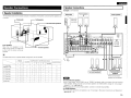
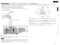
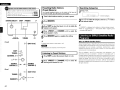
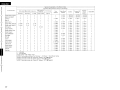
I Speaker Connections
Speaker Connections
Example: 5.1[l.1-channels
I Speaker Installation
The illustration below shows a basic example of installation of the amplifier combined with 8 speakers and
a monitor.
Subwoofer
Center speaker
I Subwoofer
I
Front speakers
A
Center speaker
o I
_ - - - - - Surround back speakers
=
E>
v
'"2
~
"C
"t
.
,
;
Q;
a
-<
"'"'"
Front speakers
Place the front speakers to the
sides of the monitor or screen and
as flush with the screen surface as
possible.
~------
Surround speakers
,.:.:
a
'"
........-====.....----------------1- -
~
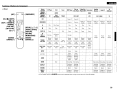
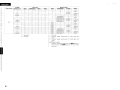
The table below shows a typical speaker configuration for the AVR-1909.
~
7.1-channels
(FRONT A+B)
7.1-channels
5.1-channels
5.1-channels
3.1-channels
2.1-channels
2-channels
FRONT
SURROUND
* L : Left
CENTER
L
R
0
0
0
0
0
0
0
0
0
0
0
0
0
0
R: Right
SURROUND BACK
SUBWOOFER
L
R
L
R
1 speaker
0
0
0
0
0
-
0
0
0
0
0
0
0
0
0
0
0
0
0
-
-
-
0
-
-
-
-
-
-
-
-
-
-
-
-
-
-
0
0
0
0
0
-
-
-
-
-
-
-
oD
=
=
Surround speakers
-11"===::::::0'1'"""'"
o
a
go 0i
=
=
I
I
~I
I
I
I
I
I
I
When surround back
speakers are connected
For surround back speakers:
• Since" Amp Assign" of AVR-1909 is set to "ZONE2" by default, audio is not output from the surround
back speakers. When using the surround back speakers with MAIN ZONE, change the "Amp Assign"
setting to "7.1ch" (Gr'page 35).
• When using just one surround back speaker, connect it to the left channel (SBl).
For ZONE2 speakers:
• For multi-zone connection and operation, see "Amp Assign / Multi-zone Connections and Operations"
(Gr'page 59 - 72)
10
ENGLISH
I
Connecting the Speaker Cables
Protection circuit
Carefully check the left (L) and right (R) channels and + (red) and (black) polarities on the speakers being connected to the AVR-1909,
and be sure to interconnect the channels and polarities correctly.
1
Peel off about 0.03 ftJI0 mm ofsheathing
from the tip of the speaker cable, then
either twist the core wire tightly or
terminate it.
2
terminal
Turn
the
speaker
counterclockwise to loosen it.
3
Insert the speaker cable's core wire to
the hilt into the speaker terminal.
4
Turn the speaker terminal clockwise to
tighten it.
When using a banana plug
Tighten the speaker terminal firmly before
inserting the banana plug.
~
~~~
JlfJi '"
~0
·n·u.
• Use speakers with an impedance of 6 to 16 O/ohms. When using
front A and B speakers simultaneously, use speakers with an
impedance of 12 to 16 O/ohms.
• Connect the speaker cables in such a way that they do not stick out
of the speaker terminals. The protection circuit may be activated if
the core wires touch the rear panel or if the + and - sides touch each
other ( & "Protection circuit").
• Never touch the speaker terminals while the power supply is
connected. Doing so could result in electric shock.
11
If the core wires touch the rear panel and the screws etc., or the ±
sides touch each other, the protection circuit will be activated and
the power indicator will flash red at intervals of 0.5 secs.
If the protection circuit is activated, the speaker output is isolated,
and the power supply goes to the standby state. If the power supply is turned off, after the power supply cord is withdrawn, please
confirm that speaker cable and input cable are connected.
Also, if replaying large sound levels by using a speaker having an
impedance less than that specified (eg, 4 O/ohmsL the temperature
will rise, and the protection circuit might be activated. The power
supply will go into the standby state, and the power indicator will
flash red at 2 second intervals.
In this case, please switch off the power supply, and wait until
the AVR-1909 has cooled down, and the surrounding ventilation is
good.
Even if there are no problems with the surrounding ventilation and
connections, in the event of the protection circuit becoming activated, due to thinking that the AVR-1909 has failed, please contact
DENON Service center after switching off.
Connecting Equipment with HDMI connectors
With HDMI connections, the video and audio signals can be transferred with a single cable.
ENGLISH
-u·j·-
The AVR-1909 cannot be controlled from another device via the HDMI cable.
The audio signals output from the HDMI connector (sampling frequency, bit rate, etc.) may be restricted
by the connected device.
o Video signals are not output properly when using devices that are not HDCP-compatible.
o Video signals are not output if the input video signals do not match the monitor's resolution. In this
case, switch the Blu-ray Disc player / DVD player's resolution to a resolution with which the monitor is
compatible.
olf the menu "Manual Setup" - "HDMI Setup" - "HDMI Audio Out" setting (u:;:rpage 32) is set to
"AMP", the sound may be interrupted when the monitor's power is turned off.
o Use a cable on which the HDMI logo is indicated la certified HDMI product) for connection to the HDMI
connector. Normal playback may not be possible when using a cable other than one on which the HDMI
logo is indicated (a non-HDMI-certified product).
o If the monitor or Blu-ray Disc player / DVD player does not support Deep Color, deep color signal transfer
is not possible.
o If the monitor or Blu-ray Disc player / DVD player does not support xvYCC, xvYCC signal transfer is not
possible.
o If the monitor does not support" Auto Lipsync Correction" function, this function will not work.
o The AVR-1909 is compatible with the HDMI's CEC (Consumer Electronics Controll function. Please note
the following .
• It may not work depending on the device it is connected to and its setup.
• It does not operate with televisions or players that are not compatible with HDMI's CEC.
o
o
o When the AVR-1909 and Blu-ray Disc player / DVD player are connected using an HDMI cable, also
connect the AVR-1909 and monitor using an HDMI cable.
• If the connected monitor or Blu-ray Disc player / DVD player only has a DVI-D connector, use an HDMI/DVI
converter cable. When using a DVI cable, no audio signals. are transmitted.
• Use a Deep Color compatible cable for connection to Deep Color compatible devices.
When connecting with an HDMI/DVI converter cable (adapter)
HDMI video signals are theoretically compatible with the DVI format.
When connecting to a monitor, etc., equipped with a DVI-D connector, connection is possible using an
HDMI/DVI converter cable, but depending on the combination of components in some cases the video
signals will not be output.
o When connecting using an HDMI/DVI converter adapter, the video signals may not be output properly
due to poor connections with the connected cable, etc.
o
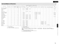
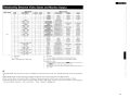
'* The
'*
AVR-1909 is equipped. for HDMI
version 1.3a. This version is compatible
with other versions, allowing connection
to all components equipped with an HDMI
connector.
The AVR-1909 is compatible with 30- and 36bit Deep Color.
Compatible
audio format
Details
Discs
(examples)
2-channellinear
PCM
2ch 32-192 kHz
16/20/24 bits
CD, DVD-Video,
DVD-Audio
Multi-channel
linear PCM
8ch 32-192 kHz
16/20/24 bits
DVD-Audio,
Blu-ray
Dolby Digital, DTS Bitstream
Dolby Digital Plus,
DolbyTrueHD,
Bitstream
DTS-HD
DVD-Video
Blu-ray
Copyright protection system (HDCP)
In order to play the digital video and audio signals of a Blu-ray, DVD- Video or DVD-Audio disc using HDMI/
DVI connections, both the connected Blu-ray Disc player / DVD player and monitor must be equipped for
a copyright protection system called "HDCP" (High-bandwidth Digital Content Protection).
HDCP is a copy protection technology consisting of data encoding and mutual identification of the
devices.
The AVR-1909 is HDCP-eompatible. For details on the Blu-ray Disc player / DVD player or monitor you are
using, refer to its operating instructions.
tIo
By default, the HDMI audio signals are output from the speakers connected to the AVR-1909.
o To output the sound from the TV, make the settings at menu "Manual Setup" - "HDMI Setup" - "HDMI
Audio Out" - "TV" (R::iT'page 32).
12
I
ENGLISH
I
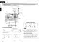
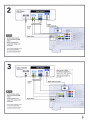
Connecting the Monitor
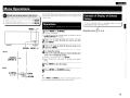
• Select the terminal to use and connect the device (Gf'page 9 "Video Conversion Function").
• With HDMI connections, the video and audio signals can be transferred with a single cable.
• To output the audio signals to the monitor with HDMI connections, set menu" Manual Setup" - "HDMI
Setup" - "HDMI Audio Out" to "TV" (Gf'page 32).
Connecting the Playback Components
Carefully check the left (l) and right (R) channels and the inputs and outputs, and be sure to interconnect
correctly.
Blu-ray Disc player I DVD player
Monitor
Select the terminal to use and connect the device.
HDMI
Blu-ray Disc player I DVD player
IN
--AUDIO-AUDIO
OUT
L
COAXIAL
OUT
R
f)f)
f)
* When connected to a Blu-ray
Disc player, and playing Dolby
TrueHD, DTS-HD, Dolby Digital
Plus HD AUDIO, connect the
HDMI.
J
iN,n•
• The component video connectors may be indicated differently on your monitor. For details, see the
monitor's operating instructions.
• The audio signals output from the HDMI connectors are only the HDMI input signals.
-
T- '
When using an optical cable for the digital audio connection, make the settings at menu "Input Setup"
- "Assign" - "Digitalin" (Gf'page 42).
13
CD player
--AUDIO-COAXIAL
OUT
o
AUDIO
OUT
L
R
00
Use a DENON control dock for iPod (ASD-l R, ASD-3N or ASD-3W sold
separately) to connect the iPod to the AVR-1909. For instructions on
the control dock for iPod settings, refer to the control dock for iPod's
operating instructions.
I
I
iPod
,c
ASD·3N/3W
{
,
~
c
o
,
<
When using an optical cable for the digital audio connection, make the
settings at menu "Input Setup" - "Assign" - "Digital In" (lI:2Wpage
42).
• With the default settings, the iPod can be used connected to the
VCR OPod) connector.
• To assign the iPod to a connector other than VCR (iPod), make the
settings at menu "Input Setup" - "(input source to which iPod dock·
assigned)" - "Assign" - "iPod dock" (lI:2Wpage 42).
14
ENGLISH
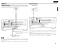
;' I TVICABLE Tuner
""
Select the terminal to use and connect the device.
TV tuner
Connecting the Recording Components
Carefully check the left (l) and right (Rl channels and the inputs and outputs, and be sure to interconnect
correctly.
~
Video Cassette Recorder
Select the terminal to use and connect the device.
Video cassette recorder
- - - - - AUDIO-----
-VIDEOHOMI
-.
OUT
AUDIO
OUT
L
R
AUDIO
IN
L
R
00 00
OPTICAL
OUT
OPTICAL
IN
IT£]
IT£]
,
When using a coaxial cable for the digital audio connection, make the settings at menu "Input Setup"
- "Assign" - "Digitalin" (lJ::§'page 42).
• When recording via the AVR-1909, the playback device's cable must be of the same type as the cable
used to connect the AVR-1909's VCR OUT connector.
Example: TV IN --+ S-Video cable. VCR OUT --+ S-Video cable
TV IN --+ Video cable. VCR OUT --+ Video cable
• When using a component video cable for the video connection, make the settings at menu "Input Setup"
- "Assign" - "Component In" (lJ::§'page 42)
l1(iU.
Do not connect the output of the component connected to the AVR-1909's OPTICAL2 output connector to
any input connector other than OPTICAL2.
15
ENGLISH
I CD Recorder I MD Recorder I Tape Deck
Make analog connections if you wish to record analog audio signals, or digital connections if you wish to
record digital audio signals, depending on the types of connectors on the components being used.
CD recorder I
MD recorder I
Tape deck
Connections to Other Devices
Carefully check the left (L) and right (R) channels and the inputs and outputs, and be sure to interconnect
correctly.
--AUDIO-AUDIO
IN
L
R
I
Video Camera I Game Console
Video camera I
Game console
AUDIO
OUT
L
R
- VIDEO-
GG GG
viDEO
,:Ot.iT
~
-AUDIOAUDIO
OlIT
L
R
GG
q lI-~, !,,-,-'~7-"7' }~u 0
-
--
o
I
I
00 0
000
I
I
16
ENGLISH
I
II...Co
...'.;..m....,.,:.p....o...n....e_n....t_w.;..it....h_M....u....l....ti....-c....h""'8""'n_n...e...I...O....u_t.:.p....u_t....c....o....n....n....e_ct...o_rs_'......................=="1 I XM connector
Blu-ray Disc player / DVD player /
External decoder
-------AUDIO - - - - - - -
I
SUB·
WOOFER
FRONT
L
R
~~
CENTER
SURROUND
SURROUND
BACK
L
R
~~
• The AVR-1909 is an XM Ready® receiver, You can receive XM® Satellite Radio by connecting to the
XM Mini-Tuner and Home Dock (includes home antenna, sold separately) and subscribing to the XM
service.
• Plug the XM Mini-Tuner and Home Dock into the XM connector on the rear panel.
• Position the Home Dock antenna near a south-facing window to receive the best signal.
For details, see "Listening to XM Satellite Radio Programs" ((iT'page 56,57).
When making connections, also refer to the operating instructions of the XM Mini-Tuner and Home
Dock.
XM Mini-Tuner and Home Dock
o
:ii.
• To play the analog input signals input to the EXT. IN connectors, press the INPUT MODE button on the
main unit or INPUT button on the main remote control unit and select "EXT. IN" or make the settings at
menu "Input Setup" - "Input Mode" - "Input Mode" - "EXT. IN" ((iT'page 41).
• The video signal can be connected in the same way as a Blu-ray Disc player I DVD player ((iT'page 13).
-n'lia
Keep the power cord unplugged until the XM Mini-Tuner and Home Dock connection have been
completed .
• The XM name and related logo are registered trademarks of XM Satellite Radio Inc. All rights
reserved.
• XM Ready® is a registered trademark of XM Satellite Radio Inc. All rights reserved.
17
ENGLISH
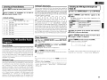
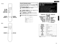
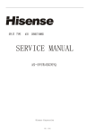
I SIRIUS connector
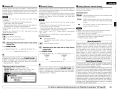
o Positioning the Antenna
• The AVR-1909 is a SIRIUS Satellite Radio Ready® receiver. You can receive SIRIUS® Satellite Radio by
connecting to the SiriusConnect Home Tuner and subscribing to the SIRIUS service.
• Plug the SIRIUS connector on the rear panel.
• Position the Home Tuner antenna near a south-facing window to receive the best signal.
For details, see "Listening to SIRIUS Satellite Radio Programs" (Gr'page 57 - 59).
When making connections, also refer to the operating instructions of the SiriusConnect Home Tuner.
For a consistent satellite signal, the antenna must be positioned correctly. Use the following map to
determine which area you are in and position the antenna accordingly.
I
SiriusConnect Home Tuner
WEST
EAST
-c
;;
-<
".
,
HORIZON
SOUTH
I.Ii
'*' When connecting digital audio
Area 1 : Point the antenna toward the sky in the east, northeast, or southeast, either through a window
or outside.
Area 2 : Point the antenna toward the sky in the north or northeast, either through a window or outside.
Area 3 : Point the antenna toward the sky in the north or northwest, either through a window or
outside.
Area 4 : Point the antenna toward the sky in the west, northwest, or southwest, either through a window
or outside.
Area 5 : Put the antenna outside and point it straight up. The antenna cannot be used indoors.
When connecting digital of the SiriusConnect Home Tuner, perform the setting" Input Setup" - "Assign"
- "Digitalin" from the menu. (Gr'page 42).
-Nlnw
Keep the power cord unplugged until the SiriusConnect Home Tuner connection have been completed.
© 2006 SIRIUS Satellite Radio Inc. "SIRIUS", the SIRIUS dog logo, and channel names and logos are
trademarks of SIRIUS Satellite Radio Inc.
18
'"
o
X"
ENGLISH
I Antenna terminals
An F-type FM antenna cable plug can be connected directly.
Direction of broadcasting station
I
AM loop antenna
[<cooli,d)
~
J
FM antenna
Jl750/0hms
rr;l Coaxial cable
~~~w......a1;.~~-.-'
o
FM indoor antenna
(supplied)
Connection of AM antennas
1. Push the
lever.
AM outdoor antenna
Ground
AM loop antenna assembly
@
Remove the vinyl tie and take
out the connection line.
WJ
a. With the antenna on top of
any stable surface.
rA\
~
n
..
o
~
~
Mount
Connect to the AM
antenna terminals.
Bend in the reverse direction.
b. With the antenna attached
toa wall.
~~~~l
Installation hole Mount on wall, etc.
19
IJ
2. Insert the
conductor.
3. Return the
lever.
II. .
¢
~
¢
~
-N'U• Do not connect two FM antennas simultaneously.
• Even if an external AM antenna is used, do not
disconnect the AM loop antenna .
• Make sure the AM loop antenna lead terminals do not
touch metal parts of the panel.
Note to CATV system installer:
This reminder is provided to call the CATV system
installer's attention to Article 820-40 of the NEC
which provides guidelines for proper grounding and,
in particular, specifies that the cable ground shall be
connected to the grounding system of the building,
as close to the point of cable entry as practical.
ENGLISH
I Multi-zone
ntroller
RF remote receiver
ZONE2 out Connections
If another pre-main (integrated) amplifier is connected, the ZONE2 out connectors can be used to playa
different program source in ZONE2 at the same time (Gr'page 69 - 72).
I
Pre-main amplifier
(ZONE2)
-AUDIOAUDIO
IN
L
R
~~
I
Extension jack for future use.
(Connect devices corresponding with room to
room function to this jack.)
AUX
OUT
Input
Infrared tr.=====~~~
retransmitter
~I:~~~~~IB!
Infrared
sensor
l
r
• When using in combination with an RF Remote Controller (RC-7000CI, sold separately) or RF Remote
Receiver (RC-7001 RCI, sold separately) two-way communica ion with an RF Remote Controller is
possible
The AVR-1909's status information as well as iPod can be browsed watching the RF Remote Controller's
display. For details, refer to the operating instructions of the respective devices.
• When used in combination with an RF Remote Controller or RF Remote Receiver, make the settings at
menu "Manual Setup" - "Option Setup" - "2Way Remote" - "Used" (~page 36).
-N·n•
• For the audio output, use high quality pin-plug cords so that no induction humming or noise is produced.
• For instructions on installing and operating separately sold devices, refer to the respective devices'
operating instructions .
• To conduct multi-zone playback, see" Amp Assign I Multi-zone Connections and Operations" (~page
69 - 72)
20
ENGLISH
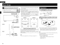
Connecting the Power Cord
Wait until all connections have been completed before connecting the power cord.
~
U.;-------~I:J
I
Power cord
To household
power outlet
(AC 120 V, 60 Hz)
Connection to the AC outlets
ll~·
-""-:.:. . --,'-----o====f
-N·n.
• These outlets supply power to external audio
equipment.
• The power supplied from these outlets turns on and
off together with the set's power switch.
• Audio equipment with a total power consumption
of 120 W (1 A) can be connected.
• Insert the AC plugs securely. Incomplete connections could cause noise.
• Only use the AC outlets to plug in audio equipment. Do not use them as power supplies for hairdryers or
anything other than audio equipment.
Once Connections are Completed
Turning the Power On (~page
21
54)
ENGLISH
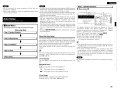
Menu Operations
&
Symbols used to indicate buttons in this manual
Button located on both the main unit and the remote control
unit
~ BUTTON
Button only on the main unit
~ <BUTTON>
Button only on the remote control unit
~ [BUTTON]
<MENU> 6. 'V
With the AVR-1909, settings and operations for most functions can be
performed by operating white looking at the menus displayed on the
monitor screen.
In lists of selectable items or adjustable ranges, the item
surrounded by a border is the default value.
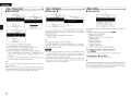
Operations
The same operation
control unit
1
*
Press
IS
Example of Display of Default
Values
possible on the main unit or main remote
<MENU> or [A.MENU).
[Selectable items]
0
B A+B
The menu is displayed.
To operate from the main remote control unit, be sure to set the
[SOURCE CONTROL 1] to "AUDIO".
2
3
4
*
* Select
[SOURCE ~
CONTROL 1)
[Rear]
<ll>
"Default Yes", then press <I to reset to the default
setting.
5
6
6. V
Press 6. 'V again to select the item you want to set,
then press ENTER.
To change the setting:
Press 6. V to select the item you want to change, then
press <I l> to change the setting.
To return to the previous item, press RETURN.
[Front]
[A. MENU) ~} '-1__
Press 6. 'V to select the item you want to set, then
press ENTER.
Press
ENTER to enter the setting.
Press
<MENU> or [A.MENU) to finish.
ENTER
I .:..t.jGjRETURN
'" ·:·1
#"
When <MENU> or [A.MENU] is pressed, the settings made up to that
point are entered and the settings menu screen turns off.
22
I
ENGLISH
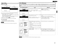
Examples of On-screen Display and Front Display
Some typical examples are described below.
[Front display]
[On-screen display]
Screen title
en .C Aut 0
Set u p)
.Manual Setup
3. Input Setup
4. Parameter
5. Information
Submenu title
I
f'1enu
Press <] to execute
Currently selected line
3-1.Assign
Current setting
:+:H55
D1 g
i:3n
[j'D i g ita I
i t.~ 1
Press <]t> to change the setting
?-:
:~
None
3-4. Rename
Use L \1 to input characters.
' - - - - - - - - - - - - - - 1 Use
I n : ~ ••,._~
iPod Dock
<]t> to change the character input
1-_ _--,
[j'DVD
position.
De f a u I t
G;J~
3-4. Rename
:+:r;~enar"le:
P2r;.~r:·le1 ~
DI..JD
C 1~3:--!
'--
--1 When
highlighted,
"Default Yes".
press
\1
to
select 1-_ _....
......
rn~~~.~
:~DVD-3930~
De f a u I t 8J~
The selected setup menu number is shown in the master volume indicator section of the display.
23
ENGLISH
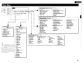
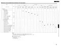
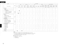
Menu Map
. . . J ~:
IT 3.
······-1 ~:
r{ Auto Setup (trpage 25 [flo
2.
3.
4.
5.
Auto Setup • • • • • • • • •
Manual Setup • • • • • • •
Input Setup • • • • • • • •
Parameter • • • • • • •
Informat ion
•
••
•••
••
• •••••••••
•••
.......... ~
••••••
••
•
•••
•
••
••••••••
••
•
...
(trpage 46 - 51)
When "Screensaver" is set to
"ON", the screensaver is activated
if no operation is performed for
about 3 minutes.
When you press D. V <l [>, the
screen saver is cancelled and the
screen before that screen saver
started is displayed.
::::I Surround Parameter
• Mode
• Cinema EQ
·DRC
• Dynamic Range Compression
• LFE
• Center Image
• Panorama
• Dimension
• Center Width
• Delay Time
• Effect Level
• Room Size
• AFDM
• SB CH Out
• SWAn
• Subwoofer
• Default
::::I Tone
• Tone Control
• Bass
• Treble
::::I Audyssey Settings
• MultEQ
• Dynamic EQ
• Dynamic Volume
• Setting
::::I RESTORER
o Night Mode
::::I Audio Delay
J
::::I Parameter Check
• Speaker Configuration Check
• Distance Check
• Channel Level Check
• Crossover Frequency Check
• EQCheck
• Restore
ri Manual Setup (trpage 29 - 37)
Parameter
::::I Status
• MAIN ZONE
• ZONE2
::::I Audio Input Signal
::::I HDMllnformation
::::I Auto Surround Mode
::::I Quick Select
::::I Preset Station
::::I Start Menu
• Step ,: Speaker Detection
• Step 2: Measurement
• Step 3: Calculation
• Step 4: Check
• Step 5: Store
29)
••
••
~
::::I Speaker Setup (t:jf'page 29 - 31)
• Speaker Configuration
• Subwoofer Setup
• Distance
• Channel Level
• Crossover Frequency
• Front Speaker Setup
::::I HDMI Setup Ia::u"page 32)
• Color Space
• RGB Range
• Auto Lipsync
• HDMI Audio Out
• HDMI Control
• Power Off Control
Input Setup (l@'page 38 ::::I TUNER (FM/AM)
• Auto Preset
• Preset Skip
• Preset Name
• Video
• Input Mode
• Rename
• Source Level
J
::::I Audio Setup Ia::u"page 33, 341
• EXT. IN Subwoofer Level
• 2ch Direct/Stereo
• Dolby Digital Setup
• Auto Surround Mode
• EQ Preset
::::IZONE2 Setup Ia::u"page 34, 35)
• Level Lch
• Level Rch
• Volume Limit
• Power On Level
• Mute Level
::::I Option Setup l(Fpage 35 - 37)
• Amp Assign
• Volume Control
• Source Delete
• On·Screen Display
• Quick Select Name
• Remote 10 Setup
• 2Way Remote
• Display
• Setup Lock
43)
::::I CD, CDR/TAPE, DVD, HOP,
TV/CBL, VCR, V.AUX
• Assign
• Video
• Input Mode
• Rename
• Source Level
• iPod
::::IXM
• Preset Skip
• Antenna Aiming
• Video
• Input Mode
• Rename
• Source Level
::::I SIRIUS
• Preset Skip
• Parental Lock
• Antenna Aiming
• Assign
• Video
• Input Mode
• Rename
• Source Level
o
;;l
24
ENGLISH
Auto Setup
&
Symbols used to indicate buttons in this manual
Button located on both the main unit and the remote control
unit
• BUTTON
Button only on the main unit
• <BUTTON>
Button only on the remote control unit
• [BUTTON]
I
MASTER VOLUME D. '1
to
"'"-r-------r--Fei=[::
RETURN ENTER.<Jl>
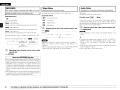
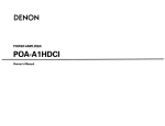
• Audyssey MultEO® automatically measures the acoustical problems
in the listening environment to create the best audio experience for
your home theater.
• Audyssey MultEO optimizes a large listening area where one or
more listeners are seated.
Measurements are performed by placing the calibrated microphone
IDM-A409) successively at multiple positions throughout the
listening area as shown in Example CD. For best results, it is strongly
recommended to measure 6 positions so that the measurements
have the proper spatial weighting.
Even if the listening environment is small as shown in Example (1),
measuring at multiple points throughout the listening environment
results in more effective correction.
Example CD
:0GJ;'I;:~:
......
/....
.
,:
'I ENTER
D. '1 <J l> I ,:-.,. ,:_,
~
L·jTRETURN
Sound ---=:::!~----~---.--..J
receptor
Place the microphone at ear height on a tripod or stand
with the microphone pointing directly up towards the
ceiling.
-'.
= )
* Do not hold the microphone in your hand during measurements.
About the main listening position (*M)
The main listening position refers to the most central position where
one would normally sit within the listening environment.
MultEO uses the measurements from this position to calculate
speaker distance, level. polarity, and the optimum crossover value
for the subwoofer.
.J·-: __
25
The auto setup screen appears automatically.
.
MASTER VOLUME
[Rear]
Connect the included calibrated setup microphone to
the SETUP MIC jack on the main unit.
l-:Measuring positions)
~ 'iJ :
' . ~ ...'
1
2
Example (1)
\ ~ rr;rr
[Front]
Preparations
To make manual adjustments to the settings, see pages 29 - 31.
Be sure that the path from microphone to the speakers is not
blocked by objects. Avoid placing the microphone close to a seat
back or wall as sound reflections may give inaccurate results.
1'"-,£;
~
When using a subwoofer, make the following settings before starting
the auto setup procedure:
• Defeat the volume and crossover controls if possible
• If this is not possible then set
• Volume: "12 o'clock" position
• Crossover frequency: "Maximum/Highest Frequency"
· Low pass filter: "Off"
· Standby mode: "Off"
ENGLISH
-n'''-
• Do not disconnect the setup microphone until the auto setup
procedure is completed.
• When using headphones. unplug the headphones before starting
the auto setup procedure.
Auto Setup
Optimize settings for speakers In use
• Start Menu
The settings found at this stage are applied automatically.
[Auto setup flow)
( Step 1: Speaker Detection
)
t
)
t
.....;..-------------'
t
t
)
( Step 2: Measurement
( Step 3: Calculation
,.
)
)
( Step 4: Check
,.
...;...---------~
( Step 5: Store
-n'''-
• Loud test sounds may be played during Audyssey MultEO automatic
speaker setup. This is part of normal operation. If there is background
noise in room, these test signals will increase in volume.
• Do not stand between the speakers and setup microphone or allow
obstacles in the path while the measurements are being made. This
will cause inaccurate readings.
• Make the room as quiet as possible. Background noise can disrupt
the room measurements. Close windows, silence cell phones,
televisions, radios, air conditioners, fluorescent lights, home
appliances, light dimmers, or other devices as measurements may
be affected by these sounds.
Cell phones should be placed away from all audio electronics during
the measurement process as Radio Frequency Interference (RFI)
may cause measurement disruptions (even if the cell phone is not in
use).
• Operating MASTER VOLUME during the measurements will cancel
the measurements.
About the Auto Setup
The Audyssey MultEO auto setup function detects the presence of
each speaker and automatically calculates the speaker size, channel
level, distance, and optimal crossover frequency setting. Audyssey
MultEO corrects acoustical distortions within the listening area.
Before starting, connect and position all of your speakers.
Once started, MultEO will playa series of test tones through each
speaker.
If an error message appears during the measurements, check" Error
Messages", take the advised action, then start the measurements
again (o:::F page 28).
o Front Speaker
The front speaker to be measured can be selected ahead of time
here.
)
( Step 1 : Speaker Detection
•
Menu screen •
CD
Auto Setup
The speaker connection and polarity are detected at the first
measurement position (main listening position). The following
attributes are also determined at this time: "Speaker Size", "Speaker
Distance", "Channel Level", "Crossover Frequency".
CD Press .6. \l to select "Amp Assign", then press ENTER,
(1) Press <1[> to select "71ch", then press ENTER.
® Press .6. \l to select "Start ", then press <1.
® Press .6. \l to select "Next ", then press <1.
• To cancel the measurements, press <1.
• If the result differs from the actual connection status or an error
message appears, use \l to on-screen display "Retry ...." and then
press <1 to repeat the measurement.
• If the result still differs from the actual connection status after
re-measurement or the error message still appears, it is possible
that the speakers are not connected properly. Turn the AVR-1909
off, check the speaker connections and repeat the measurement
process from the beginning.
-n,"-
Do not change the speaker connections or subwoofer volume after
"Step 1".
[Selectable items]
CD :Output test tone from front speakers A.
B
co
Audyssey Mu It EQ
Ste 1 :Speaker Detection
~
Fro n t S p.
y"
~ §
~
Center Sp.
Subwoofer
Front Sp. ~ A •
Sur r 0 u n d Sp. y"
IJ'Amp Assign
S. Back SP.
S tar t ~
Cancel ~
IJ'Next~
Ret r y ~
: Output test tone from front speakers B.
A+B : Output test tone from front speakers A and B.
DAmp Assign
Advanced setting: changes power amplifier assignment.
For details, refer to "Amp Assign" (r:rpage 35).
26
:::l
:::l
"
~
<3
:::l
I
'"
ENGLISH
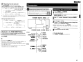
C'-S_t_e.:..p_2_:_M_e_as_u_r_e_rn_e_n_t
•
J
)
Menu screen •
•
Menu screen •
m
[J'Next4
Calculate4
Cancel4
I
)
(Step 3 : Calculation
•
m
...,....
[J'Calculate4
Ret r y 4
Cancel4
)
(Step 4 : Check
Menu screen •
m
~
_---------._
..
_
[J'Speaker Config. Check
Distance Check
Channel Level Check
Crossover FreQ. Check
Next4
[J'Ca nee I 4
The values obtained from the measurements are automatically
analyzed and the attributes for each of the speakers in the listening
area are determined.
G) Press 6. to select "Calculate "''', then press <l.
• Analysis begins.
(J"Next4
Calculate4
Ret r y 4
Cancel4
G) Press 6. to select "Next "''', then press <l.
• The measurement of the 2nd position starts.
Move the microphone to the 3rd position and press <l
• The measurement of the 3rd position starts.
® Perform 0 repeatedly for the 4th, 5th, and 6th measurments.
• "All the measurements were finished." is displayed on the onscreen display. When you have completed measurements in 6
positions
• If you want to stop after measuring just five or fewer positions,
press \l to select "Cancel"''', then press <l.
o
After completing a measurement position, move the microphone to
the next position.
Measure at 6 positions: the main listening position and 5 other
surrounding positions. Although it is allowable to measure less than 6
positions, it is recommended to measure 6 for best results.
27
• Analysis takes several minutes to complete.
• The time required for this analysis depends on the number of
speakers connected. The greater the number of speakers connected,
the longer analysis will take.
-N'U8
• Do not change the speaker connections or subwoofer volume,
or speaker locations after making measurements. If changes are
necessary, make the changes and use the Audyssey MultEO auto
setup once again for an updated EO solution.
• For instance, if the location or direction of a speaker is altered, the
Auto Setup should be performed again to ensure the correct EO
solution for the new room configuration.
When analysis is complete, check the analysis results for the following
four items.
G) Make your selection using Lc,. \l and press ENTER.
• Presence and size of speaker
"Speaker Config. Check"
• Distance of speaker from listening position
"Distance Check"
• Speaker channel level
"Channel Level Check"
• Crossover Frequency
"Crossover Freq. Check"
(1) Use 6. \l to change which speaker is displayed.
OTo switch to another analysis result item
Press RETURN
This returns you to analysis results items, so repeat step G).
OTo proceed to "Step 5: Store"
Press 6. to select "Next "''', then press <l.
Distance values that are greater than the actual distance of a speaker
may be accurate for speakers with built-in filters (subwoofers, etc).
This is because these filters add electrical delay (distance) to the signal
that is compensated for by the Auto Setup process.
ENGLISH
( Step 5 : Store
•
)
Menu screen •
CD
Error Messages
If the auto setup procedure could not be completed due to speaker installation, the measuring environment. etc., an error message is
displayed. If this happens, check the relevant items, be sure to take the necessary measures,then perform the auto setup procedure over
again.
Error messages (examples)
Measures
• Connect the included setup microphone to the SETUP
MIC jack on the main unit.
• Check the speaker connections.
• Not all speakers could be detected.
• The front L speaker was not
detected.
[J"Store~
Cancel~
The auto setup measurement results are stored in the AVR-1909.
CD Press 6. to select" Store ...... then press <3.
• "Storing Please wait··· .. is displayed on the on-screen display
while the results are being stored.
• When storing is complete, "Storing complete. Auto Setup is now
finished." is displayed on the on-screen display.
Select" Exit". then press ENTER.
® Disconnect the setup microphone from the AVR-1909.
properly
I
• Too much noise in the room for accurate • Either turn off any device generating noise or move it
measurements to be made.
away.
• Try again when the surroundings are quieter.
• Speaker or subwoofer sound is too low for • Check the speaker installation and the direction in
which the speakers are facing.
accurate measurements to be made.
• Adjust the subwoofer's volume.
en
o To cancel storing
Ret r y ~
Cancel~
Press 6. \l to select "Cancel ...... then press <3.
• All the measured auto setup data will be erased.
_Ntn.
Cause
• Included setup microphone is not connected.
Auto Setup
AudweL Mu I t EQ
t4.'~"'.
Do not turn the power off while the settings are being stored.
[J"~
-i..
Fro n t
O l ,I4
Retry~
Cancel~
Auto Setup
~~=
'I § ~
?\ Mu I t EQ
!!i!!!!i!A·U
AudW
[J' ~
• Displayed speaker could not be detected.
• Check the connections of the displayed speaker.
. The front R speaker were not properly
detected.
Only one channel of the surround speakers
was detected.
Sound was output from the R channel
when only one surround back speaker was
connected.
. The surround back. but the surround speaker
was not detected.
• Displayed speaker
polarities reversed.
Fro n t
connected
with
the • Check the polarities of the displayed speaker.
• For some speakers. this error message may be
displayed even if the speaker is properly connected. If
you are sure that the wiring is correct, select" Skip".
Ret r y
~
Cancel~
Ski ~
:ft.:. Select" Retry" to measure again.
-Ntii. Be sure to turn the power off before checking the speaker connections.
28
I
ENGLISH
II Parameter Check
Check auto setup measurement results.
This is displayed after the auto setup procedure is completed.
[Selectable items]
Speaker Contig. Check
Distance Check
Channel LavelCheck
Crossover Freq. Check
EO Check
Manual Setup
&
Make detail settings for various parameters.
Symbols used to indicate buttons in this manual
Button located on both the main unit and the remote control
)0 BUTTON
unit
Button only on the main unit
)0 <BUTTON>
Button only on the remote control unit
)0 [BUTTON]
Speaker Setup
Use this procedure to set the speakers manually or If you wish to
change the settings made with the auto setup procedure.
•
The auto setup results can be set again when "Restore" is selected.
SOURCE SELECT
Menu screen.
1
<DIMMER>
(Sl
2. Manua I
1. Auto Setup
0"2. Manua I Setup
3. I nput Setup
4. Parameter
5. I n for ma t ion
~l-rLt
<SPEAKERS>
<MENU>
<:J[>
CJ"1. Speaker Setup
2.HDMI Setup
3. Audio'Setup
4. ZONE2 Se t up
5.0ption Setup
• Speaker Configuration
Select speaker configuration and size_
(bass reproduction capability)
[Front]
Front Speaker
Select front speaker size.
[Selectable items] I Large I Small
Center Speaker
Select center speaker use and size.
[Rear]
--i661/
SOURCE
i6
enS!
SELECT
:"", ., ... '
:0 i3 6 :
~
:hd_Q.Qi·
i3'
29
I
urge I Small None
Subwoofer
Select subwoofer use.
~__:..."__, I [A. MENU]
'~';I(1)''0+:y'_o,:c... I
[Selectable items]
<l t>
I [TESn
I For details on how to select, set and cancel settings for each menu, see "Menu Operations" (!l2if'page 22).
[Selectable items]
I Yes .,
Se t up
No
ENGLISH
Surround Speaker
II'Distance
Select surround speakers use and size.
[Selectable items]
I
Large' Small
I None
- Select "Large" or "Small" not according to the physical size of the
speaker but according to the low frequency reproduction capabilities
based on the frequency set at "Crossover Frequency" (&page
Set distance from listening position to speakers.
Before making-."the •settings, measure thedista"nCe from
lis"teningcpOsition to the aifferent speakers.
me
31).
Surround Back Speaker
Select surround back speaker use and size.
[Selectable items] ( Large
(l2spkrs
ISmall I None )
I 1spkr )
INti••
Since "Amp Assign" of AVR-1909 is set to "ZONE2" by default,
audio is not output from the surround back speakers. When using the
surround back speakers with MAIN ZONE, change the "Amp Assign"
setting to "7.1 ch" (&page 35).
-When "Front Speaker" is set to "Small", "Subwoofer" can
automatically set to "Yes".
-If "Subwoofer" is set to "No", "Front Speaker" is automatically set
to "Large".
-If "Surround Speaker" is set to "None", "Surround Back Speaker"
are automatically set to "None".
- When "Front Speaker" is set to "Small", "Center Speaker" can not
be set to "Large".
- When using just one surround back speaker, connect it to the left
channel (SBU
LFE
I: Play
low range and LFE signal of channels set to
"Small".
LFE+Main : Play low range and
No
:Select this when no subwoofer is connected.
2spkrs
1spkr
Select the number of surround back speakers.
Even when the Surround Back Speaker setting is other than
"None'; sound may not be emitted from the surround back
speaker, depending on the playback source. In this case, make
a menu "Parameter" - "Surround Parameter" - "SB CH Out"
setting other than "OFF" (@"page 48).
[Selectable items]
I 1ft "I
o.1ft : Can be selected when" Feet" is set.
: Can be selected when
"Meters" is set.
Default
Resets the settings to the default values.
None :Select this when no speaker is connected.
:Select this when a subwoofer is connected.
I
Select step. (smallest distance)
[Selectable items]
frequency reproduction capabilities.
Yes
Step
Select low range signal to be reproduced bysubwoofer.
frequency reproduction capabilities.
Small :Select this when using small speakers without ample low
Select unit for distance.
I aim I O;01m
• Subwoofer Setup
Large :Select this when using large speakers with ample low
Feet / Meters
LFE signal of all channels.
~,;
- This can be set when menu "Speaker Configuration" - "Subwoofer"
is set to "Yes".
- Play music or a movie source and select the mode offering the
strongest bass.
- Select "LFE+Main" if you want the bass signals to always be
produced from the subwoofer.
Distance measurement
,~-
Select the speaker you want to set, then set the distance.
Set the value closest to the measured distance.
[Variable range]
O.Oft - &a.Oft
: Display when "Feet" is set.
0.00m -18.00m : Display when "Meters" is set.
mg
Set the distance between the listening position and the various
speakers to no more than 20.0 ft (6.00 metersl.
For details on how to select, set and cancel settings for each menu, see "Menu Operations" (Gf'page
22}.1
30
I
ENGLISH
• Channel Level
II Crossover Frequency
II Front Speaker Setup
Adjust channel levels to.obtain equal volume from all speakers.
Select crossover frequency from which subwoofer handles low
range signal.
Select front speakers to use for each surround mode.
[Selectable items]
Test Tone
[Selectable items]
Select test tone playback method.
40Hz
60Hz 180Hz 190Hz
[Selectable items]
200Hz
250Hz
I Auto I:
Automatically switch speaker from which test tone is
output
Manual : Manually switch speaker from which test tone is output.
Test Tone Start
110Hz
120Hz
150Hz
Only the portion of the bass sound of the various speakers output
from the subwoofer that has a frequency below the frequency set
here is output
Set this according to the low frequency reproduction capabilities of
the speakers you are using.
Advanced
Output test tone.
[Variable range]
100Hz
OFF
*
-12dB -
IOdB I -
Set the crossover frequency separately for the different speakers.
+12dB
* In the case of a sub woofer, reducing the volume when it is at "-12
dB" will change the setting to "OFF" (none).
Default
Resets the settings to the default values.
~ Operating from the main remote control unit
Adjusting with the main remote control unit using the test tones is
only possible in the" Auto" mode and only effective in the STANDARD
mode. The adjusted levels for the different modes are automatically
stored in the memory.
.~
-If in the "Advanced" settings, "Subwoofer Setup" (Gf'page 30)
in the menu is set to "LFE", it is possible to make this setting
for speakers set to "Small" at "Speaker Configuration". If set to
"LFE+Main", this setting can be made regardless of the speaker
size.
- For speakers set to "Small", sound below the crossover frequency
is cut from the sound output The cut bass sound is output from the
subwoofer or front speakers.
- Always set the crossover frequency to "80 Hz". When using small
speakers, however, we recommend setting the crossover frequency
to a higher frequency.
[Adjusting using test tones]
Q) Press [TESn
Test tones are output from the various speakers.
CV Use <l t> to adjust so that the volume is equal for all speakers.
® When the adjustments are completed, press [TESn again.
-When the menu "Speaker Configuration" - "Surround Back
Speaker" setting (Gf'page 30) is set to "lspkr", the surround back
speaker display is set to "Surround Back Sp." .
- Speakers set to "None" in the "Speaker Configuration" settings are
not displayed.
- When "Channel Level" is adjusted, the adjusted values are set for all
the surround modes. To adjust the channel level separately for the
different surround modes, use the operation see page 63.
31
I For details on how to select, set and cancel settings for each menu, see "Menu Operations" (~page 221.
I Nonnal I: To change the settings, select "Custom".
Custom
Make separate settings for 2-channel mode.
When set to "Custom", you can select beforehand the front speaker
to use for each surround mode.
[Selectable items]
[IJ
MULTI CH: [IJ
DIRECT/STEREO:
-N·h.
B
A+B
B
A+B
When set to "Custom", <SPEAKERS> does not operate .
ENGLISH
HDMI Setup
flRGB Range
II Power Off Control
Make settings for HOMI video/audio output
Make settings for RGB output range.
Interlock power OFF with HOMI control.
•
[Selectable items]
Menu screen •
2. Manua I
Set up
1
2-2. HDMI
1. Speaker
Setup
[1"2. HDM I Set up
3.Audio Setup
4. ZONE2 Set u p
5.0ption Set up
I Nonnal I: Use video range from 16 (black) to 235 (white)
(1'Color
RGB
Set UP
Space
YCbCr
•
Range
Normal
Auto
00
•
LmS
• c
m2-2. HDM I
setting to avoid black washout.
~
~
y nc
~OFF
When "YCbCr" is selected under "Color Space", "RGB Range" will
have no effect.
Se t up
HDMI
Audio
• AMP
HDMI
Co n t r 0 I
Power
Enhanced : Video range from 0 (black) to 255 (white). Use this
Out
~
tmJ.:~OFF
Off
Control
tmJ. : ~OFF
II Auto Lipsync
Automatic compensation for timing shift in audio and video
output.
[Selectable items]
II HOMI Audio Out
Make settings for output color space.
Select HOMI audio output device.
YCbCr
RGB
: Output using YCbCr format.
: Output using RGB format.
OFF
#.
• This can be set when" HOM I Control" is set to "ON".
'. Please consult the operating instructions for each connected device
to check the settings
·Uej··
• When the" HOMI Control" setting has been changed, always turn
off the power to the connecting devices afterwards and then turn
back on.
• The "HOMI Control" and "Power Off Control" does not work when
the power to the equipment is off.
• For details, see "HOMI Control Function" (!3T'page 62).
~ OFF
D Color Space
[Selectable items]
[Selectable items] ~
[Selectable items]
IAMP I: Use speakers connected to receiver for audio playback.
TV
: Use speakers of TV for audio playback.
-n,o.
When connected to a monitor with a OVI-O connector (HOCP
compatible) using an HOMI/OVI converter cable, the signals are output
in RGB format, regardless of this setting.
When the HOMI control function is operating, the setting of audio
playback in the connected TV takes priority (l!2ir'page 62 "HOMI
Control Function").
II HOMI Control
Make settings for HOMI control function.
[Selectable items]
ON
~
Please consult the operating instructions for each connected device
to check the settings.
'N,O.
For details, see "HOMI Control Function" ((E'page 62)
For details on how to select, set and cancel settings for each menu, see "Menu Operations" l(1f"page 22).1
32
•
ENGLISH
Front
Audio Setup
II Dolby Digital Setup
Select front speaker size.
Make settings for audio playback
Set dynamic range for downmix playback of Dolby Digital
sources.
[Selectable items]
•
(")
o
::>
::>
'"~
o'
::>
'"
ILarge I Small
Menu screen •
2. Manua I
1
Se t up
2-3. Aud i 0
1. Speaker Setup
2. HDMI Setup
IT3.Audio Setup
4. ZONE2 Setup
5.0ption Setup
Setup
ITl. EXT. IN SW Level
2. 2ch Direct/Stereo
3.Dolby Digital Setup
4. Auto Surround Mode
5. EQ Preset
I
[Selectable items]
: Select front speaker size.
ON
Subwoofer
Select subwoofer use.
~:
[Selectable items]
•
~
No
: Select subwoofer use.
Select low range signal to be reproduced by subwoofer.
[Selectable items]
Set the subwoofer level for playback.
[Selectable items]
OdB
+5dB
~ LFE+Main : Select subwoofer signal.
+1OdB
Do not use compression. This is the recommended
setting.
• Set this to "ON" if the sound from the front speakers seems
distorted.
• When not using the center speaker or surround speakers, the
playback sound is down-mixed and output from the front speakers.
Subwoofer Mode
a EXT. IN Subwoofer Level
Compression is used. Select this if sound from front
speakers is distorted.
II Auto Surround Mode
I +15dB I
Crossover
We recommend setting to "+ 15dB".
Select crossover frequency from which subwoofer handles low range
signal.
Make setting for memorizing surround mode setting for each
input signal type.
[Selectable items]
~:
[Selectable items]
fJ 2ch Direct/Stereo
40Hz
60Hz 180Hz I 90Hz
Make speaker settings for 2-ehannel mode playback.
2110Hz
250Hz : Select crossover frequency.
100Hz
110Hz
120Hz
150Hz
OFF
Memorize settings. Most recently stored surround mode is
automatically selected.
Do not memorize settings. Surround mode does not change
according to input signal.
-~~
:.-<
~
Setting
Distance FL
To change the settings, select "Custom"
Set distance from listening position to front left speaker.
[Selectable items]
[Variable range]
I Basic I: Use the same settings as in "Speaker Setup".
Custom
Make separate settings for 2-channel mode.
O.Oft - 6O.Oft
Distance FR
Set distance from listening position to front right speaker.
[Variable range]
"
O.Oft - 60.00
-n-Ua
~
o
::>
~::
Set the distance between the listening position and the various
speakers to no more than 20.0 ft (6.00 metersl.
33
I For details on how to select. set and cancel settings for each menu. see "Menu Operations" (D2!f'page 22).
• The auto surround mode function lets you store in the memory the
surround mode last used for playing the four types of input signals
listed below.
<D Analog and PCM 2-channel signals
@ Dolby Digital and DTS 2-channel signals
@ Dolby Digital and DTS multi-channel signals
® Multi-channel signals other than Dolby Digital and DTS (PCM,
etc.)
• When playing in the PURE DIRECT mode, the surround mode does
not change even if the input signal is changed.
ENGLISH
Manual EO
lJea Preset
Set MultEO related settings and Manual EO beforehand.
ZONE2 Setup
Adjust tonal quality for each speaker using graphic equalizer.
Make settings for audio playback In a ZONE2 system
o Default
Resets the settings to the default values.
EO Customize
When MultEO® and Manual EO you are not using are preset, MultiEO
can be skipped when selected on the main unit or main remote control
unit.
o
o
Menu screen •
2. Manua I
Copy the MultEO "Audyssey Flat" correction curve.
1
Setup
2-4. ZONE2
1. Speaker
Setup
2. HDMI Setup
3.Audio Setup
[J"4. ZONE2 Setup
5.0ption Setup
[Selectable items]
Yes
Before running Auto Setup
•
Base Curve Copy
No
[Selectable items]
Manual.
o
1
Used
I Not Used
"Base Curve Copy" is displayed after the auto setup procedure has
been performed.
After running Auto Setup
[Selectable items]
Audyssey Byp. LlR.
Audyssey Flat
Manual
I
o Adjust CH
Used
Not Used
I Used
Not Used
I
Not Used
Used
Direct Mode
Select "MultEO" use for DIRECT or PURE DIRECT mode.
[Selectable items]
ON
~.
Use "MultEO"
Setup
ch
Rch
:.
OdB~
:.
0 dB~
Vo I. Lim i t
: .OFF ~
Power On Lev.
Las t ~
: • Fu I I ~
Mute Lev.
[J"L eve I
L
I
-n·u.
"ZONE2 Setup" is displayed when ZONE2 is selected with "Amp
Assign" (i:Tpage 35)
Q) Select speaker adjustment method.
[Selectable items]
Each CH •Adjust tonal quality for each speaker separately
I.IR eH •Adjust tonal quality for each
All CH
DLevel Lch
LlR speaker pair.
Adjust the left channel output level.
•Adjust tonal quality for all speakers together.
@ Select the speaker and frequency band and adjust the level.
[Selectable items] 63Hz
125Hz
250Hz
2kHz
4kHz
8kHz
-20dB
-
Do not use "MultEO".
[Variable range]
I OdB I -
500Hz
[Variable range]
-12dB
-
IOdB I -
+12dB
1kHz
16kHz
II Level Rch
+6dB
Adjust the right channel output level.
[Variable range] -12dB
-
I OdB I -
+12dB
--
For details on how to select, set and cancel settings for each menu, see "Menu Operations" (Gr"page
22).1
34
I
ENGLISH
II Volume Limit
Option Setup
fJ Volume Control
Make a setting for maximum volume.
Make vanous other settings
Set the MAIN ZONE volume setting.
[Selectable items]
~:
Do not set a maximum volume.
-2OdB
Set the maximum volume to -20 dB.
-1OdB
Set the maximum volume to -10 dB.
OdB
Set the maximum volume to 0 dB.
•
Menu screen •
2.Manual
Setup
1. Speaker Setup
2. HDMI Setup
3.Audio Setup
4. ZONE2 Setup
IT5.0ption Setup
Volume Limit
1
2-5.0ption Setup
[J"1.Amp Assign
2. Vol. Control
3.Source Delete
4.0n-Screen Display
5.Quick Select Name
6. Remote ID Setup
7. 2Way Remo t e
8.Display
9. Setup Lock
[Selectable items]
I:
Last
Use the memorized setting from the last session.
Always use the muting on condition when power
is turned on.
[Variable range]
-7OdB - +18dB
Set the volume level when the power is turned on
in units of 1 dB.
Set the amount of attenuation when muting is on.
[Selectable items]
~:
The sound is cut off entirely.
-40dB : The sound is attenuated by 40 dB.
-2OdB :
The sound is attenuated by 20 dB.
Do not set a maximum volume.
-2OdB
Set the maximum volume to -20 dB.
-1OdB
Set the maximum volume to -10 dB.
Set the maximum volume to 0 dB .
Power On Level
Define how the amplifier for the surround back speaker channels
is used.
This sets the volume set when the MAIN ZONE's power is turned
on.
The places where the surround back amplifier are used can be set
freely according to the usage environment. This makes it possible to
output sound to rooms other than the room (the MAIN ZONE) where
surround playback is performed (multi-zone playback) or play the sound
with high quality using the front speakers (bi-amp connections).
[Selectable items]
[Selectable items]
[Variable range]
: The surround back channel is output from the
speakers connected to the SURR.BACK/AMP
ASSIGN terminals.
ZONEZ
:When ZONE2 power is on, the ZONE2 channel
- - - - - - is output from speakers connected to the SURR.
BACK/AMP ASSIGN terminals.
FrontA Bi-Amp . The Front A channel for Bi-Amp use is output from
the speakers connected to the SURR.BACK/AMP
ASSIGN terminals.
I: Use the memorized setting from the last session.
Last
: Always use the muting on condition when power
is turned on.
-81dB - +18dB
Set the volume level when the power is turned on
in units of 1 dB.
Mute Level
This sets the amount of attenuation of the volume when the mute
mode is set in the MAIN ZONE.
[Selectable items]
~:
The sound is cut off entirely.
FrontB Bi-Amp : The Front B channel for Bi-Amp use is output from
-40dB
The sound is attenuated by 40 dB.
the speakers connected to the SURR.BACK/AMP
ASSIGN terminals.
-2OdB
The sound is attenuated by 20 dB.
For details, see" Amp Assign / Multi-zone Connections and Operations"
(&page 69 - 72)
35
~:
.. Amp Assign
7.1ch
II Mute Level
[Selectable items]
OdB
.. Power On Level
Define the volume setting that is active when the power is turned
on.
Make a setting for maximum volume.
I For details on how to select, set and cancel settings for each menu, see "Menu Operations" (ll2iT'page 22).
ENGLISH
II Source Delete
Remove input sources that are not used from the display.
[Selectable items]
ON
I:
Use this source.
Delete
Do not use this source
Master Volume
II Quick Select Name
Master volume display during adjustment.
Change the Quick Select name.
Up to 16 characters can be input.
[Selectable items]
ON
I:Turn display on.
[Input characters]
OFF
:Turn display off.
A-Z a-z 0-9
!#%&'()*+.-./:;=H?@[\](space)
Tuner Information
Default
This sets the time the on-screen display is displayed when a tuner
operation is performed.
Resets the settings to the default values.
Resets the settings to the default values.
-n·n.
[Selectable items]
Default
• Input sources being used in the various zones cannot be deleted.
• Input sources set to "Delete" cannot be selected using SOURCE
SELECT
Always
II On-Screen Display
Make on-screen display related settings.
Screensaver
Make screensaver settings.
Use the screensaver to prevent burn-in on the monitor screen.
When set to "ON". the screensaver is activated if there is no activity
for about 3 minutes.
[Selectable items]
ON
OFF
: Activate the screensaver if there is no activity for about 3
minutes.
: Turn the screensaver function off.
Show display continuously.
Set remote control 10.
I 30sec I:
Show display for 30 seconds after operation.
10sec
Show display for 10 seconds after operation.
OFF
. Turn display off.
iPod Information
This sets the time the on-screen display is displayed when an iPod
operation is performed.
Always
[Selectable items]
ON
:Turn display on
OFF
Turn display off
-n·n.
c:=IJ
2
3
4
When using the AVR-1909 with only the included remote control
unit (RC-1099). use Remote ID "1" (default).
When using a separately sold remote control unit IRC-7000CI. etcl
this function can be used. Match the 10 setting of the remote control
unit and the receiver.
Show display continuously.
IJ 2Way Remote
I 30sec I: Show display for 30 seconds after operation.
10sec
OFF
Make setting for 2-way remote control unit.
Show display for 10 seconds after operation.
[Selectable items]
. Turn display off.
Used
IMode1 I: If there is no video signal.
: Use 2-way remote controL
I Not Used I:Do not use 2-way remote controL
Display Mode
[Selectable items]
Input source and mode display.
[Selectable items]
[Selectable items]
Select the on-screen display's display mode.
Text
I
II Remote ID Setup
flickering of the on-screen
#
When using a 2-way remote control unit (RC-7000CI and RC-7001 RCI.
sold separately), set this to "Used'"
display is not prevented.
Mode2 : Prevents flickering of the on-screen display when there is
no video signaL
Use this mode if the on-screen display does not appear
in the Mode 1. as may happen according to the TV being
used.
For details on how to select. set and cancel settings for each menu, see "Menu Operations" (02W'page
22)·1
36
I
ENGLISH
II Display
II Setup Lock
Adjust display brightness of the receiver.
Protect settings from inadvertent change.
[Selectable items]
[Selectable items]
IBright I: Normal display brightness.
ON
Reduced display brightness
Dark
Very low display brightness.
OFF
Display is off unless controls are operated.
=._ Operating from the main unit
<DIMMER>
r---
l-
Bright
OFF _
-
Dim ~
Dark
----l
When setting to "OFF", the display brightness of the menu setting in
operation changes to "Dark".
37
protection on.
~ .Turn protection off.
Dim
Press
: Turn
-When "Setup Lock" is set to "ON", the settings listed below can
no longer be changed. Also, "SETUP LOCKED!" is displayed if you
attempt to operate related buttons.
· RESTORER
· Night Mode
· Parameter
· MultEO
· Dynamic EO
· Dynamic Volume
· Channel Level
· Audio Delay
- To cancel the setting, press <MENU> or [A.MENU) to re-display the
"Setup Lock" screen, then change the setting to "OFF"
I For details on how to select, set and cancel settings for each menu, see "Menu Operations" (!GT'page 22).
ENGLISH
Input Setup
•
Use this procedure to select the input source and make the settings
related to playing input sources.
Synlbols used to indicate buttons in this manual
Button located on both the main unit and the remote control
unit
~ BUTTON
Button only on the main unit
~ <BUTTON>
Button only on the remote control unit
~ [BUTTON]
o
TUNER (AM/FM)
------------r-c!= i,J
1
OXM
<INPUT MODE>
..........
.
Displayed when
source name is
changed with
"Rename':
I
CD
[J"1.Assign
2.Video
3. I npu t Mode
4. Rename
5. Source Leve I
I
* The menu settings below can be made for these input sources
ENTER,
3 . Input
This menu is for "XM".
1-,-_ _...-_ _
•
<l[>
1.
2.
3.
4.
5.
[J"6.
Menu screen •
3.lnput
Setup
•
XM
[J"1.Preset Skip
2.Antenna Aiming
3.Video
4. Input Mode
5. Rename
6. Source Leve I
[Rear]
o
Setup
•
VCR
As sign
Video
Input Mode
Rename
Source Level
iPod
~1
3-6. iPod
[J"Repeat
Shu f fie
Mode
Mode
:
:
.
.
AI I
~
OFF
•
Changing the input source within Input Setup
SIRIUS
This menu is for "SIRIUS".
3. Input
•
[J"l.Assign
2.Video
3. I npu t Mode
4. Rename
5. Source Leve I
Menu screen •
3. Input
Setup
•
"~"
o'
,--------------,
3. I nput Setup
when "iPod dock" is set to "Assign".
~~1
o
Menu screen •
•
Setup
.C Tl.J.NJ~a ••• ~
.[FM/AM TU]
[J"1. Auto Prese·r···········
2.Preset Skip
3. Preset Name
4.Video
5. I npu t Mode
6. Rename
7. Source Leve I
VIDEO SELECT D. 'V
t
•
Menu screen •
3. I nput
n
This menu is for "CD", "CDR/TAPE", "DVD", "HOP", "TV/CBL",
"VCR", "V.AUX".
."
This menu is for "TUNER".
•
o CD, CDR/TAPE, DVD, HOP, TV/CBL, VCR, V.AUX
SIRIUS
[J"1.Preset Skip
2.Parental Lock
3. Antenna Aimi ng
4.Assign
5.Video
6. I nput Mode
7. Rename
8. Sou r ce Leve I
~
Setup
~
.
The input source currently selected in the MAIN ZONE is not changed
even when the input source within Input Setup is changed.
For details on how to select, set and cancel settings for each menu, see "Menu Operations" (&page 22)·1
38
I
ENGLISH
Settings Related to Playing Input
Sources
II Preset Name
Assign name to a preset memory.
Names containing up to 8 characters can be input.
BAtito'Preset
Al-G8
Use the auto preset function to program radio stations.
Select the preset memory number.
[Input source] I TUNER
[Input source]
I
TUNER I
[Selectable items]
Start :
•
I
[Characters that can be input]
A-Z a-z 0-9 !#%&'O*+,-./:;=U?@[\](space)
-N·"·
- It is not possible to select HDMI input signals.
- When playing HDMI video input signals, the analog video signal of
another input source cannot be selected for the HDMI video output.
-Input sources for which "Delete" is selected at "Source Delete"
cannot be selected.
- When" HDP" is set to "None" with "Manual Setup" - "Input Setup"
- "Amp Assign" - "Component In" from the menu, you cannot set
"Video Select" to "HDP".
Convert
Automatically convert video input signal to monitor output format.
Start the auto preset process.
[Input source] I OVO II HOP II TV/CBl II VCR II V.AUX I
If an FM station cannot be preset automatically, select the desired
station by tuning it in manually, then preset it manually.
[Selectable items]
• Video
~:
Setting the video source.
OFF
• Preset Skip
Set the preset memories that you do not want to display when
tuning.
Video Select
Switch video input source while listening to audio signal.
[Input source] I TUNER II CO II COR/TAPE II OVO I~
I TV/CBl II VCR II V.AUX II XM II SIRIUS I
A-G
Select the preset channel(s) you do not want to display.
[Input source] I TUNER II XM II SIRIUS I
[Selectable items]
OVO
HOP
TV/CBl
VCR
V.AUX
Select video input source to view.
[Selectable items]
~:
Display this number.
Skip : Skip this number.
When set to "Skip", it is possible to skip entire preset memory blocks
(A to G)
39
I
ISource I:
The video and audio for the same input source are played.
%
Operating from the main unit or main remote
control unit
Press VIDEO SELECT until the desired picture appears.
* To cancel, press VIDEO SELECT to select "Source".
For details on how to select, set and cancel settings for each menu, see "Menu Operations" (&page 22).
Enable conversion.
: Disable conversion.
-N·"·
When a non-standard video signal from a game machine or some
other source is input, the video conversion function might not operate.
If this happens, please set the conversion mode to "OFF".
ENGLISH
i/p Scaler
Progressive Mode
Make settings for i1p scaler function.
Select optimum progressive mode for video material.
[Input source] I OVO II HOP II TV/CBL II VCR II V.AUX I
[Input source]
[Selectable items]
[Selectable items]
IA to HI: Use i1p scaler function for analog video signal.
OFF
: Do not use i1p scaler function.
-u·na
Auto
: Automatically detect video material type.
Video1
: Select mode suitable for video playback.
Video2
: Select mode suitable for video and 30-frame film material
I
playback.
When the "Convert" setting is "OFF'; you cannot set "i1p scaler':
Resolution
I OVO II HOP II TV/CBL II VCR II V.AUX I
This can be set when" i1p Scaler" is set to "A to H':
Make settings for resolution of HOM I video output signal.
[Input source] I OVO II HOP II TV/CBL II VCR II V.AUX I
[Selectable items]
I
Auto
I:Detect monitor panel resolution and automatically set
output resolution.
480pJ576p : Output at 480p/576p resolution
Aspect
This sets the aspect ratio when outputting 480i/576i or 480p/576p
input signals from the HDMI output connector.
[Input source] I OVO II HOP II TV/CBL II VCR II V.AUX I
[Selectable items]
1080i
: Output at 1080i resolution.
Full
I:Output at 16:9 aspect ratio.
720p
: Output at nop resolution.
Normal
: Output at 4:3 aspect ratio.
1080p
: Output at 1080p resolution.
This can be set when "i1p Scaler" is set to "A to H':
This can be set when "i1p Scaler" is set to "A to H ':
-u·na
• It is not possible to convert" 1080i" signals into "nop" format.
• It is not possible to convert "nop" signals into" 1080i" format.
For details on how to select, set and cancel settings for each menu, see "Menu Operations" ((W'page 22).1
40
ENGLISH
n
o
.~"".
o'
""'
I
•
• When a digital signal is properly input, the "1Qi[]" indicator lights on
the display. If the "1Qi[]" indicator does not light, check the digital
input connector assignment and the connections.
• The surround mode cannot be set if the input mode is set to "EXT
IN':
• Only set "PCM" and "DTS" when playing the respective signals.
Input Mode
Set the input mode for this source.
~ Operating from the main unit or main remote
[Input source] I TUNER I
control unit
[Selectable items]
p~l:
C
':• •' . Play only signals from EXT IN input.
*1
Auto
-
~
I
."
o
[Input source] I CD II CDR/TAPE II DVD II HOP II TV/CBL II VCR
I V.AUX
II SIRIUS
__- - - Analog ••
HOMI
I
I
menu
menu
Set the decode mode for this source.
[Input source] I CD II CDR/TAPE II DVD II HOP II TV/CBL II VCR I
I V.AUX I
items]
I: Automatically detect input signal and perform playback. I[Selectable
Auto I: Detect type of digital input signal and decode and play
* 1: Play only signals from HDMI input. (Excluding CD and
SIRIUS)
Digital
: Play only signals from
analog input.
EXT.IN
: Play only signals from
EXT IN input.
* 1: This
*
* 2 :Play only signals from digital input.
ADalog
can be selected for input sources for which the menu
"Assign" setting is set to "HDMI In':
2: This can be selected for input sources for which the menu
"Assign" setting is set to "Digitalin" (02jf'page 42).
41
Default
Resets the settings to the default values.
--.J
[Selectable items]
.Auto
A-Z a-z !~~!t~.·U·+.-./:;=·?@[\](space)
*2
Decode Mode
s
N
[Characters that can be input]
Digital ~
"Assign" setting is set to "Digitalin" (02jf'page 42).
Automatically detect input signal and perform playback.
m:tN : Play only signals from EXT IN input.
~
EXT IN
HDMI
* 1: This can be selected for input sources for which the
"Assign" setting is set to "HDMlln':
* 2: This can be selected for input sources for which the
XM I
[Selectable items]
FJ'~<'I:
Names90l1~t~~up';'!~8~~rs~n be input.
Press <INPUT MODE> or [INPUn
Each time you press the button, the input mode display will change.
Play only signals from analog input.
[Input source]
IIRename·
Change the dis~narnef()(.thi~¥>urce.
automatically.
PCM
Decode and play only PCM input signals.
OTS
Decode and play only DTS input signals.
• This can be selected for input sources for which the menu "Assign"
setting is set to "HDMlln" or "Digitalin" (02jf'page 42)
• Only set "PCM" and "DTS" when playing the respective signals.
I For details on how to select. set and cancel settings for each menu, see "Menu Operations" (lGT'page 22).
[Variable range]
•
a2dil - 1"'81 -
+12118
For input sources for which "HDMlln" and "Digitalin" are set at the
menu "Assign" setting, the analog input level and digital input level
can be set separately.
ENGLISH
IJAssign
Assign input sources to input connectors.
Digitalin
iPod dock
Select digital input connector to assign to this source.
Assign control dock for iPod to this source.
[Input source] I CD II CDR/TAPE II DVD II HDP II TV/CBL II VCR
HDMlln
I V.AUX I
[Selectable items]
[Selectable items]
[Input source] I DVD II HDP II TV/CBL II VCR II V.AUX I
COAX1
Assign COAXIAL 1 input connector.
[Selectable items]
COAX2 :
Assign COAXIAL 2 input connector.
HDMI2 :Assign HDMI2 input connector.
om : Assign OPTICAL 1 input connector.
om : Assign OPTICAL 2 input connector.
HDMI3 :Assign HDMI3 input connector.
None
HDMI1 :Assign HDMll input connector.
: No HDMI input connector assigned.
Input source
Default setting
[Input source] I CD II CDR/TAPE II DVD II HDP II TV/CBL II VCR I
I V.AUX II SIRIUS I
Select HDMI connector to assign to this source.
None
I
OVO
HOP
TV/CBL
VCR
VAUX
HDMI1
HDMI2
None
HDMI3
None
Assign : Assign iPod input.
None
: No digital input connector assigned.
Input
CD
source
Default
COAX2
setting
CDR/
TAPE
OVO
HOP
TV/CBL
VCR
VAUX
SIRIUS
None
COAX1
None
OPT1
OPT2
None
None
• With the default settings, the control dock for iPod can be used
connected to the VCR (iPod) connector.
• Even if "iPod dock" is set to "Assign", if AVR-1909 and control dock
for iPod are not connected, the input is used as the normal input
source.
Make settings for "iPod" playback.
:1
Select component video input to assign to this source.
[Input source] I CD II CDRfTAPE II DVD II HDP II TV/CBL II VCR
[Input source] I DVD II HDP II TV/CBL II VCR II V.AUX I
"a
N
Assign component video 1 input connector.
Repeat
2-RCA
Assign component video 2 input connector.
Make settings for repeat mode.
3-RCA : Assign component video 3 input connector.
::l
I
1·RCA
'"
[Selectable items]
All
None : No component video input connector assigned.
One
Default setting
I
o
I V.AUX
[Selectable items]
Input source
I
lIiPod
Component In
• With HDMI, the video and audio signals are transferred
simultaneously. When HDMI is assigned to an input source, the
audio signal switches to HDMI along with the video signal. To use
with the digital audio input connectors assigned, set menu" Input
Mode" to "Digital".
• When the AVR-1909 and monitor are connected with an HDMI cable,
if the monitor is not compatible with HDMI audio signal playback,
only the video signals are output to the monitor.
• The audio signals input from the analog, digital and EXT. IN connectors
are not output to the monitor.
Do not assign iPod input.
OVO
HOP
TV/CBL
VCR
VAUX
1-RCA
2-RCA
3-RCA
None
None
~:
Repeat all songs.
Repeat the current song.
Cancel repeat mode.
For details on how to select, set and cancel settings for each menu, see "Menu Operations" (Grpage 22).1
42
I
ENGLISH
Shuffle
DSIRIUS Antenna Aiming
Edit Lock Code
..
Make settings for shuffle mode.
DWhen DENON control dock for iPod ASD-1R is connected
[Selectable items]
I
OFF
Shuffle songs from current album only.
I: Cancel shuffle mode.
DENON control dock for iPod ASD-3N/3W is
connected
~:
,
I
SIRIUS
Lock Setting
Cancel shuffle mode.
Set the channel radio reception limits.
CD
CIl
Press ENTER.
Using f:J. \1 <I
- If the old password is incorrectly input, "Incorrect Code" is displayed,
and proceed again from step CD
-If the password input is 3 digits or less, "Input 4-digit" is displayed,
and input again with a 4 digit password.
- If the new password is not correctly input. "Input Error" IS displayed
and the password does not change.
I
Shuffle mode on.
This can be selected for input sources for which" Assign" is assigned
at the "iPod dock" setting.
Press ENTER.
Input old password (4 digits) using f:J. \1 <II>, and press ENTER.
Input new password (4 digits) using f:J. \1 <II>, and press ENTER.
@) Input new password (4 digits) again using f:J. \1 <I 1>, and press
ENTER. If the correct password is input, "Completed" is displayed,
and the new password is modified.
CIl
®
For any channel, set the radio reception limits.
[Input source]
[Selectable items]
CD
mParental Lock
o When
ON
Signal strength is excellent
Signal strength is good
Signal strength is weak
No signal
iiiiiiliiiiiiii
s;;§!
'"
Songs . Shuffle all songs.
Albums
='"
Change the password.
1>, input the password (4 digits number) and press
ENTER.
®
Select channel by pressing f:J. \1, and set the lock by pressing
<I
1>.
[Selectable items]
1m Antenna Aiming
IUnlock I:
Check the XM and SIRIUS radio reception sensitivity.
[Input source]
I
XM
II
Lock
Do not lock selected channel(s).
Lock selected channel(s).
%' When a Parental Locked channel is tuned, "Code:
displayed, then input the password.
SIRIUS I
]" is
Satellite
Indicate satellite signal strength.
- The default password is "0000".
-If the password is wrong, "Incorrect Code" is displayed. Input the
correct password.
- While listening to the channel being played, you can also set parental
lock (@"page 59).
Terrestrial
Indicate terrestrial signal strength.
-Neil.
DXM Antenna Aiming
DisDlav
Condition
••• i:i
~i§ i~
._. !~i
iii,
""
Signal strength
Signal strength
Signal strength
Signal strength
No signal
i~i
43
I For
You can set "Parental Lock" when the input source is "SIRIUS':
is
is
is
is
strong
good
marginal
weak
details on how to select, set and cancel settings for each menu, see "Menu Operations" (@"page 22).
-N'O.
You can set "Edit Lock Code" when the input source is "SIRIUS':
ENGLISH
Surround Modes
•
Symbols used to indicate buttons in this manual
Button located on both the main unit and the remote control
unit
.. BUTTON
Button only on the main unit
.. <BUTTON>
Button only on the remote control unit
.. [BUTTON)
CD Standard Playback
This IS the mooe for enjoying surround sound according to the
program source
I Surround Playback of 2-channel Sources
47)
o DOLBY PLIIx or DOLBY PLII
: This mode is suited for movie sources.
Selecting the surround mode
Music
:This mode is suited for music sources.
Select by turning <SELECT/ENTER> or pressing [SID).
Game
: This mode is suited for games.
DOLBY PLIIx
or
DOLBY PLll
DTS NEO:6
[Rear)
Select the "Cinema", "Music", "Game" and "Pro Logic" modes at
menu "Parameter" - "Surround Parameter" - "Mode" (&page
Cinema
[Selectable items]
<SELECT/ENTER>
Select the mode to suit the source
neural
Pro Logic : This
is the Pro Logic playback mode. This can be
selected when playing with a DOLBY PLIJ decoder.
When this mode is selected, "DOLBY PL" is
displayed.
* : The signals are decoded in DOLBY PLlJx or DOLBY
PLIJ for playback
. The signals are decoded in DTS NEO:6 for
•
DOTS NEO:6
playback.
Cinema
: This mode is suited for movie sources.
~
It is possible to play analog input signals and PCM
(2-channel, 48 kHz or less) in the surround mode.
This is the optimum mode for playing sources
recorded in XM HD Surround (&page 75).
Music
:This mode is suited for music sources.
N
o
:J
'"
*:DOLBY PLIIx can be selected when surround back speakers are
being used.
DOLBY PLIJ can be selected when surround back speakers are
not being used.
[PURE]
[O/ST] ~
~ [STO]
4s G-!- [SIMU]
44
ENGLISH
I
Playing Multi-channel Sources
(Dolby Digital, DTS, etc.)
In the case of standard playback of multi channel sources, the AVR1909 recognizes the format of the multi-ehannel audio input signal and
automatically operates the appropriate decoder for surround sound.
@ DSP Simulation Playback
The desired mode according to the program source and viewing
situation can be selected from among 7 DENON original surround
modes.
The surrouGd parameters can be adjusted I&page 76, 77) to
achieve an even 'Y1ore realistic, powerful sound field
Selecting the surround mode
STANDARD
Any of the surround modes in the "Display" column in the following
table.
The mode changes depending upon factors such as the
• Input signal
• Whether or not surround back speakers
are being used.
Select by turning <SELECT/ENTER> or pressing [SIMU].
[Selectable items]
SCH /7CH STEREO
DOLBY DIGITAL
DOLBY DIGITAL EX
DOLBY DIGITAL+PLIlx CINEMA
DOLBY DIGITAL+PLfJx MUSIC
DOLBY DIGITAL Plus (*4) DOLBY DIGITAL +
DOLBYTrueHD
DOLBY HD+EX
DOLBY TrueHD (* 4)
DOLBY HD+PUlx CINEMA
DOLBY HD+PLIlx MUSIC
DTS SURROUND
DTS+PLIlx CINEMA
DTS (5.1 ch) 1
DTS+PLIlx MUSIC
DTS-ES Discrete 6.1 1
DTS+NEO:6
DTS-ES Matrix 61 1
DTS ES MTRX6.1 (* 1)
DTS 96/24
DTS ES DSCRT6.1 (* 2)
DTS 96/24 ( * 3)
DTS-HD HI RES
DTS-HD MSTR
DTS-HD (*4)
DTS-HD+NEO:6
DTS-HD+PLIlx CINEMA
DTS-HD+PLOx MUSIC
MULTI CH IN
MULTI IN+PLOx CINEMA
PCM (multi ch)
MULTI IN+PLlJx MUSIC
MULTI CH IN 71
* 1 : This is displayed when the input signal is "DTS-ES Matrix 6.1 "
and the AVR-1909's "AFDM" setting is set to "ON".
2 : This is displayed when the input signal is "DTS-ES Discrete
61 "
*3' This is displayed when the input signal is "DTS 96/24".
4: When a signal is input, the HD AUDIO indicator lights.
*
For details, see pages 78, 79.
45
* 1 :This
mode is for enjoying stereo sound
from all speakers.
ROCK ARENA
This mode is for enjoying the atmosphere
of a live concert in an arena.
JAZZ CLUB
This mode is for enjoying the atmosphere
of a live concert in a jazz club.
Displav
DOLBY DIGITAL
(other than 2ch) 1
DOLBY DIGITAL EX
*
Selecting the mode
Select by turning <SELECT/ENTER> or pressing [D/Sn
[Selectable items]
[Selectable items]
Input signal
® Direct Playback
MONO MOVIE
DIRECT
In this mode the signals bypass the tone adjustment circuitry for high
quality sound.
The sound is output to the same channels as the input signal.
* 2 :This mode is for playing monaural movie
PCM (multi ch)
sources with surround sound.
VIDEO GAME
This mode is suited for achieving surround
sound with video games.
MATRIX
This mode lets you add a sense of expansion
to stereo music sources.
VIRTUAL
This mode is for enjoying surround
effects using only the front speakers or
headphones.
* 1: "5CH
*
STEREO" is displayed when "Surround Parameter" "SB CH Out" is "OFF", and "Amp Assign" is set to "lONE2"
(a2!rpage 35, 48)
2: When playing sources recorded in monaural in the MONO MOVIE
mode, the sound will be off balance with a single channel (left or
right). so input to both channels.
Display
Input signal
Analog signal 1
PCM (2ch) 1
Dolby Digital source 1
DTS source 1
Other 2-channel diqital siqnals
DIRECT
MULTI CH DIRECT
M DIRECT + PLOx CINEMA
M DIRECT + PLOx MUSIC
M DIRECT 71
For details, see page 79
@ Stereo Playba'ck
Selecting the mode
Select by turning <SELECT/ENTER> or pressing [D/Sn
[Selectable items]
STEREO
Depending on the program source being played, it may not be possible
to achieve a satisfactory surround effect. In this case, try other modes
to achieve a sound field suited to your tastes.
.N·U-
When the input signal is DOLBY TrueHD, DOLBY DIGITAL Plus ,DTSHD you cannot select DENON original surround mode.
This is the mode for playing in stereo. The tone can be adjusted.
Sound is output from the front left and right speakers and subwoofer.
ENGLISH
Operating from the main unit
Parameter
Use <SELECT/ENTER> to select the surround mode.
ODuring PCM (2ch) I Analog I DOLBY DIGITAL (2ch)
~
DIRECT ~ STEREO ~ DOLBY PRO LOGIC!=JX
(DOLBY PRO LOGIC II)
C
7CH STEREO ~ neural
(5CH STEREO)
*~
DTS NEO:6
ROCK ARENA ~ JAZZ CLUB ~ MONO MOVIE ~
VIRTUAL
~
~
MATRIX
VIDEO GAME
_-------J
Symbols used to indicate buttons in this manual
•
Button located on both the main unit and the remote control
unit
• BUTTON
Button only on the main unit
• <BUTTON>
Button only on the remote control unit
• [BUTTON]
kHz or less) in the surround mode.
RESTORER MULTEQ <MENU>
o During Digital (Multi channell
C
~
STEREO
OCK ARENA
JAZZ CLUB
VIRTUAL
~
~
~
!
STANDARD::-l
(Dolby Digital, DTS, e~
7CH STEREO
(5CH STEREO)
~
MATRIX
MONO MOVIE ~
~ VIDEO GAME ~
~ 'V
Playback in the PURE DIRECT Mode
<MENU> or [A.MENU].
The menu is displayed.
2
Use ~ 'V to select "Parameter", then press
To operate from the main remote control unit, be sure to set the
ENTER.
To change the setting:
Press ~ 'V to select the item you want to change, then
press <l I> to change the setting.
To return to the previous item, press RETURN.
3
..,...---.----1-----
c:~f:]
1
LI:
DYNAMIC VOLUME RETURN ENTER, <H>
This is the mode that recreates the original sound most faithfully,
providing extremely high quality sound.
. ....
Press
1*
[SOURCE CONTROL 1] to "AUDIO".
* :It is possible to play analog input signals and PCM (2-ehannel, 48
DIRECT
Adjusting the parameters
*
* Select
"Default Yes", then press <l to reset to the default
setting.
4
Press
, :s:
ENTER to enter the setting.
~.
o
:l
I
I ENTER
~ 'V <ll> ~@tE
[AUDIO DELAY]
5,'.- .-, ~I [NIGHn
[Front]
III
o
To exit adjustment
:l
Press <MENU> or [A.MENU) during adjustment.
I
II
DYNAMIC =:: ..... -~
VOLUME ---:--€)I " ' ; ; /
Press [PURE].
• To cancel, press [PURE] again.
• When in the PURE DIRECT mode, the on-screen display is not
displayed and the display on the main unit is turned off.
• If the HDMI input connector is selected, video outputs are output in
the PURE DIRECT mode.
• The channel level and surround parameters in the PURE DIRECT
mode are the same as in the DIRECT mode.
"
;;
I
I
[SOURCE ~
CONTROL 1] I
[Rear]
[CINEMA]
'I
~
MULTEQ
:
I
-:-----E)I
-
[MUSIC]
~ [SID]
[A. MENU] --+----81 .-:
-;-, -:'
I ENTER
'nl· 1'8-,
.3,
1 g.
~RESTORER
I
0-
~ 'V <]1>
RETURN
46
ENGLISH
•
Surround Parameter
•
Menu screen •
4. Parameter
Adjust surround sound parameters
ITl. Surround Parameter
2. Tone
3. Audyssey Settings
4. RESTORER
5. Night Mode
6.Audio Delay
The parameters (items) which can be adjusted differ
depending upon the following conditions.
• Whether an input signal is present (when playing) or not
(when stopped, etc.).
• The type of input signal
• The type of surround mode
For details of which parameters can be adjusted in each
surround mode, see "Surround Modes and Parameters"
(Gr'page 76, 77).
fJ Cinema EO
Soften the treble range of movie soundtracks for better understanding.
[Selectable items]
ON
~:
"Cinema EO" is used.
"Cinema EO" is not used.
II DRC
Surround Parameter
Adjust surround sound parameters.
Compress dynamic range (difference between loud and soft sounds).
[Selectable items] I Auto I Low
Middle
High
OFF
The adjustable parameters differ for the different surround modes
o Surround Parameter
(Gf'page 76, 77).
o Mode
fJ Cinema EO
II
lEI
DRC
Dynamic Range Compression
g LFE
iii Center Image
IJ Panorama
D Dimension
Center Width
1m Delay Time
Effect Level
Room Size
III AFDM
lEI SBCH Out
IIll SWATT (SUBWOOFER ATT)
mJ Subwoofer
II Default
OTone
1m Tone Control
1m Bass
fE Treble
Audyssey Settings
HI MultEO
f!l Dynamic EO
fJ.I Dynamic Volume
Pm Setting
RESTORER
Night Mode
Audio Delay
This can be set in the Dolby TrueHD mode.
DMode
Select the mode to match the source (cinema source, music source,
etc.l.
o In the PLDx or PLD mode
[Selectable items]
m
m
m
o
o
o
[Selectable items]
~:
Turn dynamic range compression off.
Low
Low setting.
Music
: This is the mode for music source.
Mid
Middle setting.
Game
: This is the mode for game source.
High
High setting.
: Dolby Pro Logic playback mode (PLIl mode only).
(This is the mode for 4-channel playback (front L, front R,
center, surround (MONO).)
o In the DTS NEO:6 mode
[Selectable items]
Cinema : This is the mode for cinema source.
Music
: This is the mode for music source.
When playing DTS sources. this is only displayed for compatible
software.
BLFE
Adjust the low-frequency effects level (LFE).
[Variable range]
-10dB
-
I OdB I
~ Operating from the main remote control unit
"Cinema" mode and "Music" mode crossover operation is executed
with the main remote control unit.
Press [CINEMA] or [MUSIC]
:if
The "Music" mode is also effective for movie sources including a lot
of stereo music.
47
Compress dynamic range (difference between loud and soft sounds).
Cinema : This is the mode for cinema source.
PL
o
II Dynamic Range Compression
I For details on adjusting individual parameters, see "Adjusting the parameters" (B2W'page 46).
For proper playback of the different program sources, we recommend
setting to the values below.
• Dolby Digital sources: "0 dB"
• DTS movie sources:
"0 dB"
"-10 dB"
• DTS music sources:
ENGLISH
iii Center Image
1& Room Size
III S8 CH Out (for Multi-channel sources)
Assign center channel signal to front left and right channels for wider
sound.
Determine size of acoustic environment.
Select playback mode for surround back channels.
[Selectable items]
[Selectable items]
0.0 - 10.31 -
[Variable range]
1.0
Ii Panorama
Assign front UR signal also to surround channels, for wider sound.
If the surround effect seems weak, set" Panorama" to "ON ':
ON
[Selectable items]
~
Small
Simulate acoustics of a small room.
Med.S
Simulate acoustics of a medium-small room.
IMedium I:
OFF
No signal is played from the surround back
channels.
MTRXON
The surround channel signals undergo digital
matrix processing and are output from the
surround back channels.
Simulate acoustics of a medium room.
Med.L
Simulate acoustics of a medium-large room.
Large
Simulate acoustics of a large room.
PUIx CINEMA
* 1 : Decoded in Dolby Pro Logic IIx Cinema mode,
PLIIx MUSIC
* 2 : Decoded in Dolby Pro Logic IIx Music mode,
surround back signal played.
iii Dimension
-N·na
Shift sound image center to front or rear, to adjust playback balance.
"Room Size" does not indicate the size of the room in which sources
are played.
ES MTRX
*3 : DTS
II AFDM (Auto Flag Detect Mode!
ES DSCRT
*4 : Signal included in DTS-ES Discrete 6.1-channel
[Variable range]
0
-
W-
6
IJ Center Width
Assign center channel signal to front left and right channels for wider
sound.
[Variable range]
0
-
W-
7
Auto-select surround mode by source.
This function only works for software containing a special identification
signal.
If the software being played is recorded in Dolby Digital EX or DTS-ES,
it is played in 6.1-channels. If not, it is played in 5.1-channels.
[Selectable items]
II!] DelayTime
Example: Playing Dolby Digital software (with EX flag)
Adjust delay time to control sound stage size.
[Variable range]
0 ms - 130 ms 1 -
110 ms
- When" AFDM" is set to "ON", the surround mode is automatically
set to the DOLBY + PLUx CINEMA mode.
- To play in the Dolby Digital EX mode, set "AFDM" to "OFF" and
"SB CH Out" to "MTRX ON".
,
III Effect Level
Adjust the strength of the surround effect.
[Variable range]
~ OFF
- [ill -
15
Set to a lower level if the positioning and sense of phase of the
surround signals seems unnatural.
- Some Dolby Digital EX sources do not include EX flags. If the playback
mode does not switch automatically even when" AFDM" is set to
"ON", set "SB CH Out" to "MTRX ON" or "PLllx CINEMA".
-When the "Amp Assign" sening is "7.1ch", and using the surround
back speakers, you can set "AFDM".
surround back signal played.
signal
processing.
played
with
digital
matrix
sources played.
DSCRT ON
Mode for discrete playback of surround back
signals included in 7.1-channel digital discrete
audio signals (DVD, etc.).
* 1: This
*
*
*
can be selected when "Surround Back Speaker" is set
to "2spkrs" at the menu "Manual Setup" - "Speaker Setup"
- "Speaker Configuration" setting (G"'page 29).
2: This can be selected when "Surround Back Speaker" is set to
"2spkrs" or "lspkr" at the menu "Manual Setup" - "Speaker
Setup" -"Speaker Configuration" setting.
3: This can be selected when playing DTS sources.
4: This can be selected when playing DTS sources including a
discrete 6.1-channel signal identification signal.
Settings can also be made when [STD) is pressed.
When using surround back speakers, adopt the following
settings.
CD Adopt '71ch" for the "Amp Assign" setting.
. The default setting for the Amp Assign mode of AVR·1909 is
"ZONE2':
(?) Adopt a setting other than "OFF" for the "58 CH Out" setting
of "Surround Parameter':
For details on adjusting individual parameters, see "Adjusting the parameters" (Gf'page 46)·1
48
I
ENGLISH
III SB CH Out (for 2-channel sources)
Determine whether to use surround back speakers.
Tone
Audyssey Settings
Adjust the tonal quality of the sound.
Select room equalizer for current environment.
[Selectable items]
n
o
::l
::l
~
~
o'
::l
'"
I
ON
The surround back channel signal is played.
1m Tone Control
III MultEQ
OFF
The surround back channel signal is not played.
Turn tone adjustments off.
Select the type of room correction desired from the following list.
[Selectable items]
[Selectable items]
lID SW ATT (SUBWOOFERATT.)
Attenuate subwoofer level when using EXT IN mode.
ON
Allow tone adjustment (treble, bass).
OFF
Playback without tone adjustment.
Audyssey
Optimize frequency response of all speakers.
Audyssey Byp. UR
Optimize frequency response of speakers
except front Land R speakers.
Audyssey Rat
Optimize frequency response of all speakers
to flat response.
Manual
Apply frequency response set with "Manual
EO" (~page 34).
[Selectable items]
ON
The input from the subwoofer channel is attenuated.
~.
The tone cannot be adjusted when in the DIRECT mode.
The input from the subwoofer channel is not attenuated.
Usually use in this mode.
·iI~
Set this to "ON" if the subwoofer channel level seems too high when
playing audio signal.
1m Subwoofer
Turn subwoofer output on and off.
[Selectable items]
~.
OFF
-N"·-
When the "Dynamic EO" setting is "ON': setting is not possible.
The subwoofer is used.
. The subwoofer is not used.
OFF
1m Bass
Adjust low frequency range (bass).
[Variable range]
•
L--- OFF
Audyssey _ _ Manual
Audyssey Byp. UR ~
- - Audyssey Flat
-------J
-6dB-+6dB
~ Operating from the main unit or main remote
it Treble
control unit
Adjust high frequency range (treble).
Press MULlED
[Variable range]
-When "Audyssey", Audyssey Byp. UR" or "Audyssey Flat" is
selected, " ~~~~~SEY " lights.
-6dB -+&IB
. . Default
Resets the settings to the default values.
~
I. Turn equalizer off.
"Bass" and "Treble" can be set when "Tone Control" is set to "ON':
- After running Auto Setup, if the Speaker Configuration, Distance,
Channel Level, and Crossover Frequency have changed without
increasing the number of speakers measured, only "~~~SEY"
lights.
- "Audyssey", "Audyssey Byp. UR" and "Audyssey Flat" can be
selected after the auto setup procedure has been performed.
- After performing "Auto Setup", the "MultEO" setting automatically
becomes "Audyssey".
-If the settings of speakers for which "None" has been determined
at "Auto Setup" are changed, "Audyssey': "Audyssey Byp. UR" and
"Audyssey Flat" cannot be selected. Either perform Auto Setup
again, or return to the setting after running Auto Setup with "Auto
Setup" - "Parameter Check" - "Restore".
- MultEO and Manual EO set to "Not Used" with "Manual Setup"
- "Audio Setup" - "EO Preset" - "EO Customize" ((1Tpage 34) on
the menu, cannot be selected.
- When using headphones, "MultEO" is set to "OFF':
49
I For details on adjusting individual parameters, see "Adjusting the parameters" (~page 46).
ENGLISH
fa Dynamic EO
f!1 Dynamic Volume
11 Setting (Dynamic Volume Setting)
Audyssey Dynamic EO solves the problem of deteriorating sound
quality as volume is decreased by taking into account human perception
and room acoustics. Audyssey Dynamic EO works in tandem with
Audyssey MultEO to provide well-balanced sound for every listener
at any volume level.
Audyssey Dynamic Volume solves the problem of large variations in
volume level between television programs, commercials, and between
the soft and loud passages of movies.
Audyssey Dynamic EO is integrated into Dynamic Volume so that as
the playback volume is adjusted automatically, the perceived bass
response, tonal balance, surround impression, and dialog clarity
remain the same.
Can be set when" Dynamic Volume" is set to "ON"
Set Dynamic Volume effect.
• N.h8
• "Dynamic EO" can only be set when auto setup has been
performed.
• "Dynamic EO" cannot be set in the following situations.
• If "Auto Setup" fails to be completed.
• After running Auto Setup, when the number of used speakers has
increased from the number of measured speakers.
• When "MultEO" is set to "OFF'; "Dynamic EO" is automatically set
to "OFF':
• When you set "Dynamic EO" to "ON'; "Tone Control" and "Night
Mode" are switched "OFF':
[Selectable items]
~:
OFF
Use Dynamic EO function.
Do not use Dynamic EO function
~ Operating from the main unit or main remote
Press
C
-
control unit
DYNAMIC VOLUME.
'N'08
• "Dynamic Volume" can only be set when auto setup has been
performed.
• "Dynamic Volume" cannot be set in the following situations.
• If "Auto Setup" fails to be completed.
• After running Auto Setup, when the number of used speakers has
increased from the number of measured speakers.
• When "MultEQ" is set to "OFF'; "Dynamic Volume" is automatically
set to "OFF':
• "Dynamic Volume" and "Night Mode" cannot be used jointly.
[Selectable items]
ON
~:
Do not use Dynamic Volume.
~ Operating from the main unit or main remote
Dynamic EO / Volume: DN ------ Dynamic EO : DN / Volume: OFF ~
Dynamic EO / Volume: OFF ....- - - - - -
Use Dynamic Volume.
The Dynamic Volume effect will be at the level of the
"Setting" .
Press
control unit
DYNAMIC VOLUME.
Dynamic EO / Volume: ON
Before running Auto Setup and after running Auto Setup, if the number
of speakers has increased or you pressed DYNAMIC VOLUME, "Run
Audyssey" is displayed. In this case, either perform Auto Setup again,
or return to the setting after running Auto Setup with "Auto Setup"
- "Parameter Check" - "Restore".
OOperating conditions for each function
• Dynamic EO: When "MultEO" is set to "ON"
• Dynamic Volume: When "Dynamic EO" is set to "ON"
• Setting: When "Dynamic Volume" is set to "ON"
Dynamic EO : ON / Volume: OFF
"Green"
"Red"
Dynamic EO / Volume: OFF
Before running Auto Setup and after running Auto Setup, if the number
of speakers has increased or you pressed DYNAMIC VOLUME, "Run
Audyssey" is displayed. In this case, either perform Auto Setup again,
or return to the setting after running Auto Setup with "Auto Setup"
- "Parameter Check" - "Restore".
[Selectable items]
IMidnight I: High setting affects volume the most. causing all sounds
to be of equal loudness.
Evening
Middle setting prevents loud and soft sounds from
being much louder and softer respectively than average
sounds.
Day
Low setting provides the least adjustments to the
loudest and softest of sounds.
·N·h8
• "Setting" can only be set when auto setup has been performed.
• "Setting" cannot be set in the following situations.
• If "Auto Setup" fails to be completed.
• After running Auto Setup, when the number of used speakers has
increased from the number of measured speakers.
• If "Dynamic Volume" setting is "OFF':
•
About Dynamic EO
Audyssey Dynamic EOTM solves the problem of deteriorating sound
quality as volume is decreased by taking into account human
perception and room acoustics. Dynamic EO selects the correct
frequency response and surround levels moment-by-moment at
any user-selected volume setting. The result is bass response,
tonal balance, and surround impression that remain constant
despite changes in volume. Dynamic EO combines information
from incoming source levels with actual output sound levels in the
room, a prerequisite for delivering a loudness correction solution.
Audyssey Dynamic EO works in tandem with Audyssey MultEO to
provide well-balanced sound for every listener at any volume level.
About Dynamic Volume
Audyssey Dynamic Volume™ solves the problem of large variations
in volume level between television programs, commercials, and
between the soft and loud passages of movies.
Dynamic Volume looks at the preferred volume setting by the user and
then monitors how the volume of program material is being perceived
by listeners in real time to decide whether an adjustment is needed.
Whenever necessary, Dynamic Volume makes the necessary rapid
or gradual adjustments to maintain the desired playback volume
level while optimizing the dynamic range. Audyssey Dynamic EO is
integrated into Dynamic Volume so that as the playback volume is
adjusted automatically, the perceived bass response, tonal balance,
surround impression, and dialog clarity remain the same whether
watching movies, flipping between television channels, or changing
from stereo to surround sound content.
For details on adjusting individual parameters, see "Adjusting the parameters" ((jf"page
46).1
50
N
o
'""
I
ENGLISH
RESTORER
Night Mode
Audio Delay
This function restores compressed audio signals to how they
were before compression and corrects the sense of volume of
the bass and treble to obtain richer playback sound.
Optimized setting for late-night listening.
Compensate for mismatched timing between video and audio.
[Selectable items]
[Selectable items]
~:
OFF
Do not use RESTORER.
Mode1 (RESTORER 64):
Optimized mode for compressed sources with very weak highs.
Mode2 (RESTORER 96):
Apply suitable bass and treble boost for all compressed sources
Mode3 (RESTORER HO)
Optimized mode for compressed sources with normal highs.
The default setting for "iPod" is "Mode3". All others are set to "OFF"
When set to something other than "OFF",
C
OFF
Set the dynamic range compression of the output audio.
"!lIIimlml"
is displayed.
----- Mode 1 ----- Mode2
(RESTORER 64)
(RESTORER 961
Mode 3
(RESTORER HO)
[Variable range] I 0 ms
Turn night mode off.
Low
Low setting.
Mid
Middle setting.
High
High setting.
Press [NIGHH
The "1mmiI" indicator lights when "Low", "Mid" or "High" is
selected.
C_
H~:; _---M-id-~
-N,u8
• When the" Dynamic EO" setting is "ON ': setting is not possible.
• When the "Dynamic Volume" setting is "ON': setting is not
possible.
• When a HD-Audio (DOLBY DIGITAL Plus, DOLBY TrueHD, DTS-HD)
signal is input. the "Night Mode" can not be selected.
~ Operating from the main unit or main remote
control unit
Press RESTORER.
About the RESTORER function
• Such compressed audio formats as MP3, WMA (Windows Media
Audio) and MPEG-4 MC reduce the amount of data by eliminating
signal components that are hard for the human ear to hear. The
RESTORER function generates the signals eliminated upon
compression, restoring the sound to conditions near those of the
original sound before compression. It also corrects the sense of
volume of the bass to obtain richer sound with compressed audio
signals .
• This is displayed on the menu and can be set when the input source
IS selected to "XM ': or analog signals (including AM/FM and SIRIUS
signals) or PCM signals (fs = 44.1/48 kHz) are input.
51
I-
200 ms
If you wish to adjust the "Audio Delay" while playing HDMI or
component video signals, press c:,. to set "OSD" to "OFF". This way
the audio delay can be adjusted while watching the picture. (Press 1::.
again to switch to the on-screen display.)
~ Operating from the main remote control unit
O FF
- __
_ __
Delay audio.
This sets the delay time for audio signals.
I For details on adjusting individual parameters, see "Adjusting the parameters" (ll2!r'page 46).
~ Operating from the main remote control unit
Press [AUDIO DELAY].
-N·U8
• When operating by remote control, the onscreen display is not
shown.
• This cannot be adjusted when playing in the EXT. IN, DIRECT or
STEREO mode (with "Front Speaker" set to "Large", "Tone
Control" to "OFF" and "MultEO", "RESTORER" and "Night Mode"
to "OFF".)
• When the auto lip sync correction function is operating, you can set
within the range 0- 100 ms.
• Store" Audio Delay" for each input source.
ENGLISH
Information
•
Symbols used to indicate buttons in this manual
;
.:
Status
•
1
Shows Information about audiO Input signals
•
Shows Information about current settings
<STATUS>
Audio Input Signal
Information can be called out directly by pressing <STATUS>.
Button located on both the main unit and the remote control
unit
• BUTTON
Button only on the main unit
• <BUTTON>
Button only on the remote control unit
• [BUTTON]
Menu screen •
5. I n lor ma t ion
IT1. Status
2. Audio Input Signal
3. HDM I I n lor ma t ion
4. Auto Surround Mode
5.Quick Select
6.Preset Station
Menu screen •
5. I n lor ma t ion
)
1. Status
IT2.Audio Input Signal
3.HDMI Information
4. Auto Surround Mode
5.Quick Select
6.Preset Station
5-2.Audio
5-1. Status
Select
Name
Source:DVD
:Rename
Surround Mode:
DOLBY PLlIx cinema
Input
Mode
:Analog
Surround Mode
[Items to be checked]
Select Source
Rec Select
Dynamic En
Name
Surround Mode
Video Select
Source level
Dynamic Volume
Input Mode
SIGNAL: Dol by Dig ita I
Is
:48kHz
For ma t : 3/2/. 1
01Iset:-4dB
The currently set surround mode is displayed.
The input
displayed.
signal's
sampling
frequency
is
Format
The number of channels in the input signal (front,
surround, LFE) is displayed.
Offset
The dialogue normalization correction value is
displayed.
Flag
"MATRIX" is displayed if the input signal has
undergone matrix processing, "DISCRETE" if the
input signal has undergone discrete processing.
MultEn
Night Mode
I
EX
The input signal type is displayed.
fs
Shows information about settings for MAIN ZONE.
The items displayed differ according to the input source.
Surround Mode:
DOLBY DIGITAL
Signal
[Items to be checked]
SIGNAL
DMAIN ZONE
Input
RESTORER etc
Dialogue normalization function
If)ZONE2
Shows information about settings for multi-zone.
This is automatically activated when playing Dolby Digital sources.
This function automatically corrects the standard signal level for
individual program sources.
The correction value can be checked using <STATUS>.
[Items to be checked]
Power
Select Source
Volume level
I
,
..",: .:. ":+. .: '.): .'" 4
('! oi:' .:> .~...~.
::::1 ::::
I
The figure is the correction value when the standard level is
corrected.
52
ENGLISH
HDMllnformation
Auto Surround Mode
Preset Station
Shows ,nformat,on about HDMI Input Signals and monitor
Shows ,nformat,on about auto surround mode settings
The surround mode for which the last memory function was used
for the different Input Signal types IS displayed
Shows Information about preset stations
•
Menu screen •
5. Information
1
5-3. HOM I
1. Status
I
2.Audio Input S i g n a I
[J'3. HOMI Information
4. Au t 0 Surround Mode
5.Quick Select
6. Preset Station
S i gna I
I n f o.
•
Color
RGB
II!
Pixel Depth
8 bit s
1EJ 5 - 3 . HOMI
Moni tor
Menu screen •
1
1. Status
2.Audio Input Signal
3. HOMI Information
cr4. Auto Surround Mode
5.Quick Select
6.Preset Station
Space
4:4:4
In f o.
Interface
HOMI
Support Resolution
480 i /p
576 i /p
1080 i : 5 OHz/6 OHz
720p: 50Hz/60Hz
1 080 p : 50 Hz/ 60Hz
1080p:24Hz
5-4
Auto
Surround Mode
[Analog] [PCM]
2eW STEREO
CH
IN
[Items to be checked]
Analog/PCM 2CH
Digital2CH
Resolution
Color Space Pixel Depth
fI HOMI Monitor Information
Digital5.1CH
Multi ch
Quick Select
Shows Informatron about qUick select settings
Menu screen •
1
5. I nformat ion
1. Status
2.Audio Input Signal
3. HOMI I nformat i on
4. Auto Surround Mode
[J'5.Quick Select
6. Preset Stat ion
5-5.Quick
Select
cr1.Quick
2.Quick
3.Quick
Select
Select
Select
The HDMI monitor information is displayed.
[Items to be checked]
[Items to be checked]
Interface
Support Resolution
Name
Input Source
Input Mode
Volume Level
Dynamic EQ
Dynamic Volume
Front Sp
Digital5.1CH
Multi ch Analog/PCM 2CH
MultEQ
Digital 2CH
For instructions on storing settings at Quick Select 1 to 3, see page
64.
53
Station
I TUNER II XM II SIRIUS I
.~
When <STATUS> is pressed, the set's status can be checked on the
display.
•
3
[Input source]
5-6. Preset
A1F1\ 87. 50MHz
A2F1\89.10MHz
A3F1\ 98. 10MHz
A4F1Jl07.90MHz
A5F1J 90. 10MHz
A6F1J90.10MHz
A7F1J 90. 10MHz
WA8F1J 90. 10M z
[Items to be checked] A1 - GB
The HDMI input signal information is displayed.
C
1
1. Status
2.Audio Input Signal
3.HOMI Information
4.Auto Surround Mode
5.Quick Select
cr6. Preset Station
[0 i g ita I]
2~:OOLBY PLllx cinema
5. l~:OOLBY/OTS SURROUND
[Mu I t i c h]
:MULTI
• HOMI Signal Information
[Items to be checked]
Menu screen •
5. I nformat i on
5. Information
Resolut ion
480p
•
ENGLISH
Pia back
•
Symbols used to indicate buttons in this manual
Button located on both the main unit and the remote control
unit
.. BUTTON
Button only on the main unit
.. <BUTTON>
Button only on the remote control unit
.. [BUTTON]
Preparations
~ Turning the Power On
1
The power indicator lights red and the power is set to the
standby mode.
._--------------_._------------
<sou~
2
Press <ON/STANDBY> or [ON/SOURCE].
The power indicator flashes green and the power turns on.
'* Also press SOURCE SELECT when in standby mode, the power
'*
~l
~
I~OVVER>
turns on. In this case the input source is selected by remote
control unit.
Also press [OUICK SHECn when in standby mode, the power
turns on. In this case Ouick Select is selected.
Turning the Power Off
(j)Press <ON/STANDBY> or [OFF]
The power is set to the standby mode.
c.vPress <POWER>.
The power indicator turns off, and so does the power.
<SPEAKERS>
<ON/STANDBY>
[Front]
Press <POVVER>.
(1
[OFF] -li2-.,,~~,,~~
[OUICK SELECn ---"-'I~._.g- ..cp~
[ON/SOURCE]
:© © ©:
[SOURCE SELECn ---;00:
..©.L.©.jQ2,
'a
-u·n.
• Power continues to be supplied to some of the circuitry even when
the power is in the standby mode. When leaving home for long
periods of time or when traveling, either press <POWER> to turn off
the power, or unplug the power cord from the power outlet.
• When the multi-zone power is switched on, and you want to switch
off the main zone power, press [OFF].
I Operations During Playback
Adjusting the Master Volume
Either turn <MASTER VOLUME> or press [MASTER
VOLUME].
[Variable range]
---
-80.0dB - +18.0dB
_N.n.
The adjustable range will differ depending upon factors such as the
type of input signal and the channel level setting.
Turning Off the Sound Temporarily (Muting)
Press [MUTING].
,
To cancel, press [MUTING] again. Muting can also be canceled by
adjusting the master volume.
Listening with Headphones
Plug the headphones into the PHONES jack on the main
unit.
The sound from the speakers and pre-out connectors is automatically
cut.
-u·n.
Be careful not to set the volume too high when using headphones.
i·(~Y
[MASTER
l0TVOLU MEl
'" G-+-
I
'-' -.'"' ':
:00
:6001
[SOURCE SEL ECT] ~I
[Rear]
I
_""..:
lOOO:
---loJSJ
[MUTING]
II Selecting the Input Source
Select the source using SOURCE SELECT.
Turn <SOURCE SELECT> or press [SOURCE SELECT] to switch
between input sources.
,
Switching the front speakers
Press <SPEAKERS>.
~
~
FrontA
FrontB
FrontA+B
~
-~
If "Rec Select" is selected for the input source, press <SOURCE>
before turning <SOURCE SELECT>.
54
I
ENGLISH
Symbols used to indicate buttons in this manual
•
Button located on both the main unit and the remote control
unit
~ BurrON
Button only on the main unit
• <BurrON>
Button only on the remote control unit
~ [BUTTON]
Playing Video and Audio
Equipment
c6
I
SHIFT
<PRESET>
--~
~
@To tune in manually (Manual Tuning)
Press [MODE] to turn off the display's" AUTO" indicator, then use
TUNING to select the station you want to hear.
Prepare the equipment.
G)Load the BD, DVD, CD or other software in the player.
(~See the operating instructions of the respective equipment.)
@To playa video equipment, switch the monitor input.
((iT'See the monitor's operating instructions.)
2
3
Use SOURCE SELECT to select the input source.
If the desired station cannot be tuned in with auto tuning, tune it in
manually.
o When tuning in stations manually, press and hold TUNING to change
frequencies continuously.
o The time for which the on-screen display are displayed can be set at
"Manual Setup" - "Option Setup" - "On-Screen Display" ((iT'page
o
36),
Start playback.
(@"'See the operating instructions of the respective equipment.)
<STATUS> BAND TUNING
fI
[Front]
SOURCE SELECT
l;5f~~iJI
:_©L©_
S§2;
Presetting Radio Stations
(Preset Memory)
The remote control unit can be used to operate external devices.
See "Remote Control Unit Operations" (@"'page 65)
[SAT TU1/2]
[TUNER]
Tune in the desired broadcast station.
Q)To tune in automatically (Auto Tuning)
Press [MODE] to light the "AUTO" indicator on the display, then
use TUNING to select the station you want to hear.
Basic Operation
1
<SOURCE SELECT>
4
Your favorite broadcast stations can be preset so that you can
tune them in easily. Up to 56 stations can be preset.
1
-----_._--2
[MEMORY].
Tune in the broadcast station you want to preset.
Listening to FMIAM Broadcasts
.--------
Press
II Basic Operation
SHIFT --+--©
TUNING~
[CHANNEL+/-]
<SOURCE SELECT>
1
[SOURCE CONTROL 1]
2]
2 CONTROL
3 BAND
~
~
[SOURCE I .,---=-:::~1I" I [SOURCE
CONTROL l]r~~ I CONTROL 2]
Set
. i6G+-L- [TUNER]
I
SOURCE SELECT
~I:99Qi.1
~Qoo:
:0:
TUNING ~I~0;
'-"":
55
g
to "AUDIO" and [SOURCE
to "TUNER".
4
5
Press <PRESET> or [CHANNEL +/-] to select the
preset number (1 to 8).
to select "FM" or "AM".
o
Press [MEMORY] again to complete the setting.
To preset other stations, repeat steps 1 to 5.
Stations can be preset automatically at menu" Input Setup" - "Auto
Preset" (@"'page 39)
-N·na
[MODE]~
!
Press SHIFT to select the block (A to G) in which the
station is to be preset.
o
:.ojjj-:- [SAT TU1/2]
[MEMORY]
3
((iT'page 65 "Remote Control Unit Operations ")
Press
[Rear]
or press [TUNER] to
Either turn
select "TUNER".
Preset stations are erased by overwriting them.
BAND
ENGLISH
I Listening to Preset Stations
1 SHIFT
Press
2
to select the memory block (A to G).
Press <PRESET> or [CHANNEL +/-] to select the
desired preset channel (I to 8).
o Default settings
Auto tuner presets
Al -A8
87.5/89.1/98.1 1107.9/90.1/90.1/90.1 I
90.1 MHz
Bl - B8
520 I 600 11000 11400 11500 11710 kHz,
90.1/90.1 MHz
Cl - C8
90.1 MHz
Dl - D8
90.1 MHz
El - E8
90.1 MHz
Fl - F8
90.1 MHz
Gl - G8
901 MHz
XM Ready® Subscription
Once you have installed the XM Mini-Tuner Home Dock, inserted the
XM Mini-Tuner, connected the XM Mini-Tuner Home Dock to your
XM Ready® audio system, and installed the antenna, you are ready
to subscribe and begin receiving XM programming. There are three
places to find your eight character XM Radio ID: On the XM MiniTuner, on the XM Mini-Tuner package, and on XM Channel O. Record
the Radio ID below for reference.
DDDDDDDD
Note: The XM Radio ID does not use the letters "I", "0", "S" or
"F". Activate your XM Satellite Radio service in the U.S. online at
http://activate.xmradio.com or call 1-800-XMRADI0 (1-800-9672346). Activate your XM Satellite Radio service in Canada online at
https:llactivate.xmradio.ca or call 1-877-GET-XMSR (1-877-438- 9677).
You will need a major credit card. XM will send a signal from the
satellites to activate the full channel lineup. Activation normally takes
10-15 minutes, but during peak busy periods you may need to keep
your XM Ready audio system on for up to an hour. When you can
access the full lineup on your XM Ready audio system you are done.
Basic Operation
Listening to XM Satellite Radio
Programs
About XM Radio
XM IS North America's number one satellite radio company, offering
an extraordinary variety of commercial-free music, plus the best in
premier sports, news, talk radio, comedy, children's and entertainment
programming, broadcast in superior digital audio quality coast to coast.
For more information, or to subscribe, U.S. customers visit xmradio.
com or call XM Listener Care at 1-800- XMRADIO (1-800-967-2346);
Canadian customers visit xmradio.ca or call XM Listener Care at 1-877GETXMSR (1-877-438-9677)
XM Ready® Legal
XM monthly service subscription sold separately. XM Mini-Tuner and
Home Dock required (each sold separately) to receive XM service.
It is prohibited to copy, decompile, disassemble, reverse engineer,
hack, manipulate or otherwise make available any technology or
software incorporated in receivers compatible with the XM satellite
Radio System. Installation costs and other fees and taxes, including a
one-time activation fee may apply. All fees and programming subject
to change. Channels with frequent explicit language are indicated with
an XL. Channel blocking is available for XM radio receivers by calling
1-800-XMRADI0 (U.S. residents) and 1-877-GETXMSR (Canadian
residents). XM Service only available in the 48 contiguous United
States and Canada. ©2008 XM Satellite Radio Inc. All rights reserved.
Either turn <SOURCE SELECT> or press [SAT TU1/2]
to select "XM".
--------------_..._------ - - - - Set [SOURCE CONTROL 1] to "AUDIO" and [SOURCE
CONTROL 2] to "TUNER".
1
2
3
Checking the XM Signal Strength and
Radio 10
1
2
Either turn <SOURCE SELECT> or press [SAT TU1/2]
to select "XM".
Press <STATUS> until "SIGNAL" appears on the
display.
The display will switch as shown below, depending on the
reception conditions.
..
!~,
GOOD
MARGINAL
WEAK
NO
3
4
5
Signal strength is good
Signal strength is marginal
Signal strength is weak
No signal
I
Adjust the position of the antenna until "SIGNAL:
GOOD" is shown on the display.
Press <STATUS> until the station you want to check
(example: "XMOOI") is displayed.
Press TUNING and select channel 0 (XMOOO).
The radio ID is shown on the display.
,'1'3"'' '
;;;::.;,;,+;~,:L
Radio ID
(I§'page 65 "Remote Control Unit Operations")
Use TUNING to select the station.
When the station is tuned in, the name of the track and artist
are displayed.
The strength of both the XM satellite and terrestrial Signals can be
checked at menu" Input Setup" - "Antenna Aiming" (I§'page 43).
• The channel switches continuously when TUNING is pressed and
held.
• The artist name, track name, category and reception level can be
checked by pressing <STATUS>
• The time for which the on-screen display are displayed can be set
at menu "Manual Setup" - "Option Setup" - "On-Screen Display"
II§' page 36)
56
ENGLISH
Symbols used to indicate buttons in this manual
•
Button located on both the main unit and the remote control
unit
• BUTTON
Button only on the main unit
• <BUTTON>
Button only on the remote control unit
• [BUTTON]
<SOURCE SELECT>
(6
I
L Y'
SHIFT <PRESET>
.J......
t
r
,,'0,,,
~t?J
L
TUNING
<STATUS>
Your favorite broadcast stations can be preset so that you can
tune them in easily. Up to 56 stations can be preset.
1
Tune in the broadcast station you want to preset.
2
Press [MEMORY].
3
4
5
Press SHIFT to select the block (A to G) in which the
station is to be preset.
Press <PRESET> or [CHANNEL +/-] to select the
preset number (1 to 8).
Press [MEMORY] again to complete the setting.
<It>
~ [SAT TU1/2]
[Front]
Presetting Radio Stations
(Preset Memory)
-N,h-
SHIFT~
[CHANNEL +/-1
II Listening to Preset Stations
~.
LY'<lt>+@
[SOURCE
CONTROL 1]
1_ -.-
r
I
[Rear]
TUNING ---l~i
r'~'
[SOURCE
CONTROL 2]
J
[SAT TU1/2]
lej
;(.51
~?:,~ L Y' <It>
[MEMORY] ~ [chi
I
57
1
Press <l
__
2
t>.
.2;:'.ti.~.!. .:~ :. -P-, -,~';~,:~•'.~:!T~ -.f=:"'=::JL
Channel category
Use <l t> to select the category, then use
the desired station.
L Y' to select
• "LOADING" is displayed while stations or data are being received.
• Refer to "Troubleshooting" - "XM Satellite Radio" regarding other
messages ((1f'page 85).
Listening to SIRIUS Satellite Radio
Programs
What is SIRIUS Satellite Radio?
To preset other stations, repeat steps 1 to 5.
Preset stations are erased by overwriting them.
TUNING~
I Searching Categories
1
Press SHIFT to select the memory block (A to G).
2
Press <PRESET> or [CHANNEL +/-] to select the
desired preset channel (1 to 8).
Simply The Best Radio on RadioTM with all your favorite entertainment
including 100% commercial-free music, plus superior sports coverage,
uncensored talk and comedy, world-class entertainment, news,
weather and more for your car, home or office. For more information
visit sirius.com or siriuscanada.ca
Sirius is available in the US for subscribers with addresses in the
continental US and is available in Canada for subscribers with a
Canadian address. Required subscription plus compatible SIRIUS tuner
and antenna are required and sold separately. SIRIUS Programming is
subject to change. Visit sirius.com for the most complete and up-todate channel lineup and product information. "SIRIUS" and the SIRIUS
dog logo and related marks are trademarks of Sirius Satellite Radio Inc.
All rights reserved.
ENGLISH
I Basic Operation
<SOURCE SELECT>
1
[SOURCE CONTROL 1]
2 CONTROL
Either turn
to select "SIRIUS".
Set
or press [SAT TU1/2]
to "AUDIO" and [SOURCE
2] to "TUNER".
(&page 65 "Remote Control Unit Operations")
3
Checking the SIRIUS Signal Strength
and Radio 10
1
2
Use TUNING to select the station.
When the station is tuned in, the name of the track and artist
are displayed.
Either turn <SOURCE SELECT> or press [SAT TU1/2]
to select "SIRIUS".
Press <STATUS> until "SIGNAL" appears on the
display.
The display will switch as shown below, depending on the
reception conditions.
EXCELLENT
~.
• The channel switches continuously when TUNING is pressed and
held.
• SIRIUS Radio stations can be preset using the same procedure as
for FM/AM stations (&page 55 "Presetting Radio Stations (Preset
Memory)" and "Listening to Preset Stations").
You cannot perform" Auto Preset".
• The track name, artist name, composer name, category and reception
level can be checked by pressing <STATUS>.
• The time for which the on-screen display are displayed can be set
at menu "Manual Setup" - "Option Setup" - "On-Screen Display"
(&page 36).
*
GOOD
WEAK
NO SIGNAL
3
4
5
Signal strength is excellent
Signal strength is good
Signal strength is weak
No signal
Adjust the position of the antenna until "SIGNAL:
EXCELLENT" is shown on the display.
Presetting Radio Stations
(Preset Memory)
Your favorite broadcast stations can be preset so that you can
tune them in easily. Up to 56 stations can be preset.
1
Tune in the broadcast station you want to preset.
2
Press [MEMORY].
3
4
5
Press SHIFT to select the block (A to G) in which the
station is to be preset.
Press <PRESET> or [CHANNEL +/-] to select the
preset number (l to 8).
Press [MEMORY] again to complete the setting.
Press <STATUS> until the station you want to check
(example: "SR001") is displayed.
To preset other stations, repeat steps 1 to 5.
Press TUNING and select channel 0 (SROOO).
Channel No. and Sirius ID are alternately shown on the display.
* Write your own SIRIUS ID for storage use.
Sirius ID:
~;
The strength of both the SIRIUS and terrestrial signals can be checked
at menu "Input Setup" - "Antenna Aiming" l(W'page 43).
IN.h.
Preset stations are erased by overwriting them.
Listening to Preset Stations
1
Press SHIFT to select the memory block (A to G).
2
Press <PRESET> or [CHANNEL +/-] to select the
desired preset channel (1 to 8).
58
I
ENGLISH
&
Symbols used to indicate buttons in this manual
Bunon located on both the main unit and the remote control
~ BUTTON
unit
Bunon only on the main unit
~ <BUTTON>
Bunon only on the remote control unit
~ [BUTTON]
<SOURCE SELECT> <STATUS>
cb~
ENTER, <Jt>
[iPOd]~
[~l
[
....
~~]
[
Channel category
I Parental Lock
1
[OFF] ~
+oot[ll]
~
,~~]~
I
,
I,
.
ENTER
6. <Jt> ~(Q(T
[SOURCE 1._ ~.. 1f'~'
[SOURCE
CONTROL 1] r
I
The mus'c on an ,Pod can be played by using the control dock for
,Pod (ASD-1 R, ASD-3N or ASD-3W sold separately)
The operation can also be performed uSing the buttons on the main
un,t or remote control unit while watching the menus.
Press
• "UPDATING" is displayed while the encording code is being
updated.
• "SIRIUS UPDATING" is displayed when updating SIRIUS tuner
firmware.
• Refer to "Troubleshooting" - "SIRIUS Satellite Radio" regarding other
messages (~page 85).
<ON/STANDBY>
[Front]
iPod® Playback
Use
to select the category, then use 6. \1 to select
the desired station.
,,:;
I
I Searching Categories
1 <J t>.
LI_~ct!.~ l. .'0. . :'~_!. . . t:.~£J,:,:!: .!,~ ~!: := =L
2 <J t>
2
3
4
-
* The iPod may only be used to copy or play contents that are not
copyrighted or contents for which copying or playback is legally
permitted for your private use as an individual. Be sure to comply
with applicable copyright legislation.
~
Basic Operation
1
Make the necessary preparations.
(DSet the iPod in the DENON control dock for iPod.
(~See the control dock for iPod's operating instructions.)
(1)Assign the control dock for iPod's input.
The input for the control dock for iPod is assigned to VCR by
default.
TIme to the channel you want to lock.
MENU : "Input Setup" - "Assign" - "iPod dock"
Press ENTER for at least 3 seconds.
"Code: [ J" is displayed.
Enter the 4-digit lock code using 6. \1 <J
iPod is a trademark of Apple Inc., registered in the U.S.
and other countries.
(13f" page 42)
t>.
When you enter the correct code, the corresponding channel is
locked.
2
Either turn <SOURCE SELECT> or press [iPod] to
select the input source assigned in step 1-0 above.
IPod
[I)l
Press ENTER.
DENON
\1
CONTROL 2]
[Rea~
I
[iPod] -+--0
I'e:
[TUNING+/-] --'-'Il~j
[MODE] -+-€3 ~:,'1
.... ,..
6. \1 <Jt>
.:., '" .:. I
:01 I ENTER
59
OK to disconnect.
• Channels under Parental Lock cannot be tuned in by performing
Tuning Up/Down or by category search.
• Channels stored in preset memory can be tuned in by the preset
channel select operation, even if Parental Lock is applied.
• When a channel to which Parental Lock is applied is being played,
Parental Lock for that channel is cancelled by ~erforming Step2
• See "Edit Lock Cord" (l3f"page 431 for the method of changing
Parental Lock Cord.
• You can also set "Parental Lock" from the menu 1I3f"page 431.
'*
(,Pod screen)
If the screens above are not displayed, the iPod may not be
properly connected. Try connecting again.
Set [SOURCE CONTROL 1] to "AUDIO" and [SOURCE
to "iPodlNETWORK".
3 CONTROL 2]
1I3f"page 65 "Remote Control Unit Operations")
[MODE] and hold it down for a 2 seconds or
4 Press
more to select the display mode.
To switch between modes, press and hold down the button.
When remote mode is active, "Remote" is displayed.
[Selectable mode]
Display location
Playable
files
Audio file
Video file
Active
buttons
I Browse mode I I Remote mode I
Main unit display
iPod display
0
0
0*1
0*2
Remote
control unit
(AVR-1909)
0
0
iPod
X
0
I Listening to Music
'1
Use b. "V to select the menu, then press ENTER or l>
to select the music file to be played.
1
2 Press ENTER or l>.
Playback starts.
OStopping playback temporarily
During playback, press ENTER or [~l
ENGLISH
•
• To check the name of the title, the artist or the album when playing
in browse mode, press <STATUS>.
• The folder name and the file name can be displayed in browse
mode. Only alphanumeric characters and certain symbols can be
displayed. Any characters that cannot be displayed are replaced with
" . (period)".
• The time for which the on-screen display are displayed can be set
at menu "Manual Setup" - "Option Setup" - "On-Screen Display"
- "iPod Information" (~page 36)
<i
(
Press again to resume playback.
* 1 : When using an ASD-3N or ASD-3W control dock for iPod.
* 2 : Video may not be output, depending on the combination of
ASD-1 Rand iPod.
OFast-forwarding or fast-reversing
During playback, either press and hold [~] (to fast-reverse) or
[~] (to fast-forward)
OTo cue to the beginning of a track
During playback, either press [~] (to cue to the previous track) or
[. . .] (to cue to the next track).
~:
OTo stop
• With the default settings, the iPod can be used connected to the
VCR (iPod) connector.
• Use the RESTORER mode to expand the low and high frequency
components of compressed audio files and achieve a richer sound.
The default setting is "Mode3" (~page 51).
• Press <ON/STANDBY> or [OFf] and set the AVR-1909's power to
the standby mode before disconnecting the iPod. Also switch the
input source to one to which the menu "iPod dock" is not assigned
before disconnecting the iPod.
• When using an ASD-3N or ASD-3W control dock for iPod, refer to
the respective manual to operate.
OPlaying repeatedly
Press [TUNING -l
During playback, either press and hold ENTER or press
[Selectable items] All
One
[-l
IOFF I
)
OShuffling playback
Press [TUNING +l
• When DENON control dock for iPod ASD-1R is
connected
Songs
IOFF I
(MENU: "Input Setup" - "iPod" - "Shuffle" (~page 43)
)
• When DENON control dock for iPod ASD-3N/3W is
connected
[Selectable items]
ON
IOFF I
Photo and video data on the iPod can be viewed on the monitor.
Only for iPod equipped with slideshow or video functions. (When
using an ASD-1 R)
1 Press and hold [MODE] to set the Remote mode.
Watching the iPod's screen, use
2 "Photos"
or "Videos".
(MENU: "Input Setup" - "iPod" - "Repeat" (~page 42)
[Selectable items] Albums
Viewing Still Pictures or Videos on the
iPod
3
b. "V to select
Press [ENTER] until the image you want to view is
displayed.
ifa.'
~
• "TV Out" at the iPod's "Slideshow Settings" or "Video Settings"
must be set to "On" in order to display the iPod's photo data or videos
on the monitor. For details, see the iPod's operating instructions.
• When viewing an iPod video file, select "iPod" - "Video" in browse
mode. (When using an ASD-3N or ASD-3W)
-N'U• Depending on the type of iPod and the software version,
somefunctions may not operate.
• DENON will accept no responsibility whatsoever for any loss of iPod
data.
60
I
ENGLISH
Other Operations and Functions
&
Symbols used to indicate buttons in this manual
Button located on both the main unit and the remote control
unit
~ BUTTON
Button only on the main unit
~ <BUTTON>
Button only on the remote control unit
~ [BUTTON]
"#:"
Other Operations
Recording on an External Equipment
(REC OUT mode)
You can listen to one program source while recording a different
program source.
I
<SOURCE SELECT>
6
'-r-----1~_---.-------.-J
N
o
<ZONE2/REC SELECT>
::>
<1l
1
Press <ZONE2/REC SELECT>.
"ZONE2 SOURCE" is shown on the display.
ZONE2 SOURCE --- ZONE2 TUNER --- .... --- ZONE2 SIRIUS
t
RECOUT SIRIUS ---
2
t
--- RECOUT TUNER --- RECOUT SOURCE
Turn <SOURCE SELECT> until "RECOUT Source" is
displayed.
The ". ." indicator lights.
3
Turn <SOURCE SELECT> to choose the input source
to be recorded.
4
Play the program source.
For operating instructions, refer to the respective equipment's
operating instructions.
To record FM or AM broadcasts, select the broadcast ((1f'page
55).
5
61
Start recording.
For operating instructions, refer to the respective equipment's
operating instructions.
• To cancel, press <ZONE2/REC SElECT>, then turn <SOURCE
SElECT> until "ZONE2 Source" is displayed.
• Make a test recording before starting the actual recording.
• Sources selected with the REC OUT mode are output from ZONE2
as well.
• In the REC OUT mode, the remote control unit's ZONE2 mode
buttons cannot be operated.
• The "XM" and "SIRIUS" digital audio output signals are not output
from the OPTICAL2 output connector.
• The source selected for ZONE2 is output from the digital output
connector (OPTICAL 2).
-N'U4
• Digital signals are not output from the analog REC OUT connector.
• Recordings you make are for your personal enjoyment and should
not be used for other purposes without permission of the copyright
holder.
• Input sources for which "Delete" is selected at "Source Delete"
cannot be selected.
ENGLISH
Convenient Functions
HOM' Control Function
When AVR-1909 is connected to a TV and player compatible ~itli
HDMI control function, you can perform the following QPerations:
Settings other than AVR-1909 settings must be made·on the
respective devices. (Check the operating instructions of each
device for details.)
.
• AVR-1909 power off can be linked to the TV power off step.
When you set "Output audio from amp" in the TV audio output setup
operation, you can switch the amp power on.
• You can switch audio output devices with aTV operation.
(When outputting from the TV speakers, output switches from
speakers connected to AVR-1909l.
• You can adjust AVR-1909 volume in the TV volume adjustment
operation.
• You can switch AVR-1909 functions through linkage to TV input
function switching.
• When playing the player, the AVR-1909 input function switches to
the function of that player.
Connections
Player compatible
with HOMI
control function
Television compatible with
HOMI control function
--AUOIO-AUDIO
O\JT
HOMI
HOMI
OUT
IN
l
IE)
IE)
~
~
OPTICAl
O\JT
R
GG
X
[@]
I
I
~it
• When you want to listen to TV audio by AVR-1909, connect optical
digital or analog.
If the TV you are using has both connection jacks, use the optical
digital connection.
.When using these functions set as follows: menu "Manual Setup"
- "HOMI Setup" - "HOMI Control" (lI2if"page 32).
1--
1m
•
r:::::f~····.
)
-N,hWhen using the HOM I control function, do not assign HOMI input to "TV!
CBL" by setting "Input Setup" - "Assign" - "HOMlln" in the menu.
62
ENGLISH
II
Operations
Symbols used to indicate buttons in this manual
Button located on both the main unit and the remote control
unit
• BUTION
Button only on the main unit
• <BUnON>
Button only on the remote control unit
• [BUTIONI
<SPEAKERS>
<INPUT MODE>
I
1
Connect the HOMI to the AVR-1909 with equipment
compatible with the HOMI control function (lGFpage
62).
2
3
Put the power on for all the equipment connected to
theHOMI.
out.
<POWER>
[Front]
QUICK SELECT <SELECT/ENTER>,
<JI>
QUICK SELECT irf!S~JJ2~~0J
'<;5-:
f::::. V
<11>
._)~~---+----:8- '"' .
'--10:---
[CH SELECT/
ENTER]
1
63
4
Switch the television input to the HOMI connected to
the AVR-1909.
5
6
Switch the AVR-1909 input to the HOMI input source
and check if the picture from the player is ok.
Press <SELECT/ENTER> or [CH SELECT / ENTER].
Channe I
FR
SW
Vo I urne
SR
O. OdB SBR
O. OdB SBL
O. OdB SL
I
I
O.
O.
O.
O.
odB
odB
odB
odB
Fad e r
FRONTC .REAR
2
3
Use L:::. \l, <SELECT/ENTER> or [CH SELECT / ENTER]
to select the speaker.
The speaker that can be set switches each time one of the
buttons is pressed.
Use <1 I> to adjust the volume.
'* In the case of a sub woofer, reducing the volume when it is at
"-12 dB" will change the setting to "OFF" (none).
Put the television power on" standby and check if the
AVR-1909 goes into standby.
If the AVR-1909 does not work please check the following.
• Is the menu "Manual Setup" - "HOMI Setup" - "HOMI Control"
((Fpage 32) set to "ON"?
• Is the menu" Manual Setup" - "HOMI Setup" - "Power Off Control"
((Fpage 32) set to "ON"?
• Is the control function used for the television HOMI properly set 7
(Check the television operating instructions for details.)
• Should any of the operations below be performed, the interlocking
function may be reset, in which case, repeat step's 2 and 3
• Menu "Input Setup" - "Assign" - "HOMI In" (D2W"page 42) setting
has changed.
• There is a change to the connection between the equipmen and
the HOMI, or an increase in equipment.
[Rear]
1
Check the settings for all the equipment connected to
the HOMI and make HOMI available to them.
'* Please consult the operating instructions for the connected
equipment to check the settings.
'* Steps 1-3 do not have to be repeated once started.
'* Carryout steps 2 and 3 should any of the equipment be plugged
'-r---jr-"-f~-"~[;j
Channel Level
You can adjust the channel level either according to the playback
sources or to suit your taste, as described below.
-N,n.
When the input source is "iPod': you cannot perform channel level
setting.
Fader Function
This function lets you adjust (fade) the sound from all the front or
rear speakers at once.
1
Press <SELECT/ENTER> or [CH SELECT / ENTER].
Press L:::. \l, <SELECT/ENTER> or [CH SELECT
to select "Fader".
._ - - ._-_._--_._Use <11> to adjust the volume of the speakers.
2 ENTER]
3
I
(<I: front, [>: rear)
• The fader function does not affect the subwoofer.
• The fader can be adjusted until the volume of the speaker adjusted
to the lowest value is -12 dB.
ENGLISH
Quick Select Function
Last Function Memory
With this function, the currently playing input source, input mode,
surround mode, MultEQ settings and volume can be stored in the
memory.
This stores the settings as they were directly before the standby
mode was set.
When the power is turned back on, the settings are restored to as
they were directly before the standby mode was set.
1
2
Set the input source, surround mode, MuItEQ,
Dynamic EQ, Dynamic Volume, Front Speaker
settings and volume to the conditions you want to
store.
Press and hold the desired QUICK SELECT until
"Memory" appears on the display.
Backup Memory
The various settings are backed up for about 1 week, even if the
power is turned off or the power cord is disconnected.
,
L'
I
The current settings will be memorized.
Resetting the Microprocessor
[Quick Select Defaults]
Quick Select 1
Quick Select 2
Quick Select 3
Input Source
DVD
TV/CBl
VCR
Volume
-40 dB
-40 dB
-40 dB
• To call out the settings, press aUiCK SELECT at which the desired
settings were stored.
• The Quick Select name can be changed (iGf'page 36).
.N.h.
Input sources stored with the quick select function cannot be selected
if they have been deleted at menu" Manual Setup" - "Option Setup" "Source Delete" (iGf'page 36). In this case, store them again.
Perform this procedure if the display is abnormal or if operations
cannot be performed.
When the microprocessor is reset, all the settings are reset to
their default values.
1
Turn ofT the power using <POWER>.
2 <INPUT<POWER>
MODE>
3
Press
while simultaneously pressing
and <SPEAKERS>.
Once the display starts flashing at intervals of about 1
second, release the two buttons.
If in step 3 the display does not flash at intervals of about 1 second,
start over from step 1.
Personal Memory Plus Function
This function sets the settings (input mode, surround mode, HOM I
output mode, MultEQ, Dynamic EQ, DynamicVolume, audio delay
etc.) last selected for the individual input sources.
When you switch to an input source, the settings are automatically
set to the ones that were set the last time that input source was
used.
.,
:.
The surround parameters, tone settings and the volumes of the
different speakers are stored for the individual surround modes.
64
ENGLISH
_.
1
Remote Control Unit Operations
Main Remote Control Unit
(RC-1099)
I Operating DENON Audio Components
1 [SOURCE CONTROL 1]
Set
[Front]
[SOURCE
_--=~H'~'
[SOURCE
CONTROL 1] ~ CONTROL 2]
I
'.
2
3
to "AUDIO".
Set [SOURCE CONTROL 2] to the position for the
component to be operated (CD, iPodINETWORK or
TUNER).
Operate the audio component.
* For details. refer to the component's operating instructions.
* While this remote control is compatible with a wide range of
infrared controlled components, it may be the case that some
component models cannot be operated with this remote control.
• The signals for the pressed buttons are emitted while setting the
preset memory. To avoid accidental operation, cover the remote
control unit's transmitting window while setting the preset
memory.
• Depending on the model and year of manufacture, this function
cannot be used for some models, even if they are of makes listed in
the list of preset codes.
• Some manufacturers use more than one type of remote control code.
Refer to the included list of preset codes to change the number and
verify correct operation,
• The preset memory can be set for one component only among the
following DVD/HDP and SAT/CABLE.
• VDP (Video Disc Player) can be preset when [SOURCE CONTROL 2]
is set to "DVD/HDP".
I Operating Preset Components
Presetting
[Rear]
r
;;
[ZONE2 OFF] ,
[NUMBER]
~1
9
• DENON and other makes of components can be operated by
setting the preset memory.
• Operation is not possible for some models.
[MAIN ONI
:888:
----188 0!
!_Q,0.-~)
:..Q))
.~
Depending on the model and year of manufacture of your equipment,
some buttons may not operate.
65
1
1
* Set to the AUDIO side for the CD position, and to the VIDEO side
for the DVD/HDP, VCR, SAT/CABLE or TV position.
Set [SOURCE CONTROL 1] to "AUDIO" or ''VIDEO''.
* Set to the AUDIO side for the CD position, and to the VIDEO side
for the DVD/HDP, VCR, SAT/CABLE or TV position.
2
Set [SOURCE CONTROL 2] to the component to be
registered.
.
3
The indicator starts flashing .
Press [ZONE2 OFF] and [MAIN ON] at the same time.
4
Press [NUMBER] and input the 3-digit number of the
brand of the component to be preset. The numbers
are shown in the Preset Code Table (IGf'End of this
manual).
5
To store the codes of another component in the
memory, repeat steps 1 to 4.
Set [SOURCE CONTROL 1] to "AUDIO" or ''VIDEO''.
2
3
Set [SOURCE CONTROL 2] to the component you want
to operate.
Operate the component.
* For details, refer to the component's operating instructions.
* Some models cannot be operated with this remote control unit.
I
ENGLISH
Functions of Buttons
by Component
o Front
[OFF]
[~],
[.], [SHim,
[II], [~],
(6
5''
f~a--:----t]l
[SKIP + / FAVORITE],
i~ i
[TUNING], ~ ® , J
[.... ~], i~l
[~~],~!
[CH +/-]
[ON/SOURCE]
.:::::::~______
:0tn\0~
i'~
@J -1
!Q
' Q.!
[SETUP],[~ V <It>],
[AUDIO], [ENTER],
[DISPLAY] .
,
[RETURN],
[MENU/GUIDE]
[SOURCE
t: ..:._~~;;;;: [SOURCE
CONTROL 1] ~ CONTROL 2]
0 = 0
Device
operated
SOURCE
CONTROL 1
SOURCE
CONTROL 2
CD Player
iPod
Tuner
i Blu-ray Video Disc Video Deck
DVD Player:: 0'ISC PlaVI
a er Plaver (VDP)
AUDIO
Satellite
Receiver
Cable TV
TV
(Monitor)
VIDEO
CD
iPod/
NETWORK
TUNER
OFF
-
-
-
Power off
Power off
-
-
-
-
-
ON/SOURCE
-
-
-
Power on
Power on
Power on /
Standby
Power on /
Standby
Power on /
Standby
Power on /
Standby
Power on /
Standby
~
Play
Play / Pause
-
Play
Play
Play
Play
•
Stop
Stop
-
Stop
Stop
Stop
Stop
SHIFT. II
Pause
-
Shift
Pause
Pause
Pause
Pause
Disc skip +
* Favorites
-
Disc skip
-
-
-
Manual
search
(fast-reverse
/ fastforward)
Manual
search
(fast-reverse
/ fastforward)
Manual
search
(fast-reverse
/fastforward)
Manual
search
(fast-reverse
/ fastforward)
Manual
search
(fast-reverse
/ fastforward)
Punch
through
Punch
through
Tuning
down / up
Manual
search
(fast-reverse
/ fastforward)
Punch
through
Auto search
(cuel
Tuner
Auto search
(cue)
Channel- / +
i Auto search
CH+-
Auto search
(cue)
(cue)
Auto search
(cue)
SETUP
-
-
-
Setup
Setup
-
-
-
-
-
~'V<ll>
-
Cursor
-
-
Cursor
operation
Cursor
operation
Cursor
operation
-
-
-
Cursor
operation
Switching
the audio
signal
-
AUDIO
Cursor
operation
Switching
the audio
signal
-
-
-
-
-
ENTER
-
Enter
-
Enter setting
-
-
Enter setting
Enter setting
Enter setting
DISPLAY
-
-
-
Switching
the display
Switching
the display
-
-
Switching
the display
Switching
the display
Switching
the display
RETURN
-
-
-
Return
Return
-
-
Return
Return
Return
-
Calling out
the menus
Calling out
the menus
-
Calling out
the menus
Calling out
the menus
Calling out
the menus
....
SKIP+!
FAVORITE
....
TUNING.
.......
~
~.
MENU/
GUIDE
-
Direct
-
DVD/HDP
i Enter setting
VCR
SAT /CABLE
TV
I
S
!I N~
Switch
channels
I' ;0-
(-,+)
I ~
I, -g'~
o
-
<:
aiD
III
::r
o
* The iPod/NETWORK's FAVORITE button can be operated when using a control dock for iPod ASD-3N/3W
66
o
I ~.
n
I
I
o
~
0'
~
OJ>
ENGLISH
ORear
[NUMBER]
rGj-OQ'!
---:800:
(0-9, +10)
:000:
'--'l~J;~)j
[TUNING +/-] ,
'(r)
[TV VOL +/-],
I'';!
[MODE / TOP MENU],
i~~O--0-C}
. ..,.:
[ BAND / ~d"
'Q'0~0~
PICTURE ADJUSn,
[MEMORY / SUBTITLE]
Ic5i o
:.."1,,"
0
(j1
)
Device
oDerated
SOURCE
CONTROL 1
SOURCE
CONTROL 2
[SETUP],
[6 V <l [>],
[AUDIO],
[ENTER],
[DISPLAY],
[RETURN]
CD Player
iPod
Tuner
NUMBER
(0 - 9. +10)
-
-
TUNING
(+,-11
TVVOL(+.-)
EB CD
Random
eCD
Repeat
MODE.
TOP MENU
-
EB iPod
Random
e iPod
Repeat
Page search
mode (onceI
and Browsel
Remote
mode
switching
(Press and
holdl
SETUP
-
-
-
.6.\7<1[>
-
-
-
AUDIO
BAND.
PICTURE
ADJUST
ENTER
MEMORY.
SUBTITLE
-
-
-
RETURN
Defauh
setting
(Preset code)
Special
Remarks
Video Disc
Video Deck
Player IVDPI
Satellite
Receiver
Cable TV
TV
(Monitor)
VIDEO
CD
DISPLAY
Blu-ray Disc
Player
AUDIO
iPodl
NETWORK
I
DVD Player ~
TUNER
Number
Number
Number input 1
input /Track
input 1Track
Track selection
selection
selection
EB Blu-ray Disc
EB DVD
EBTV
EB Tuning up
Random
Volume .l
Random
e Tuning
e Blu-ray Disc
eTV
e DVD
down
Repeat
Repeat
Volume'
TV
-
Channels
Channels
Channels
EB TV
Volume .l
eTV
Volume'
EB DBS
Volume .l
e DBS
Volume'
EB Cable
Volume .l
e Cable
Volume'
EBTV
Volume .l
eTV
Volume'
-
-
Calling out
the menus
Calling out
the menus
Calling out
the menus
-
-
-
-
-
Cursor
operation
Cursor
operation
Cursor
operation
-
Switch
search
modes
SAT 1CABLE
VCR
DVD/HDP
Calling out
the menus
Calling out the
top menus
Setup
Cursor
operation
Audio
-
-
-
Setup
Cursor
operation
Audio
-
-
-
-
-
*1 Top menu
AM/FM
switching
Picture
adjust
Picture adjust
-
-
-
-
-
*1 Favorite
memorv
Preset
memory
Enter setting
Enter setting
-
-
Enter setting
Enter setti ng
Enter setting
Subtitle
Subtitle
-
-
-
-
-
-
-
-
-
-
-
Switching the
display
Return
-
-
Switching
the display
Return
-
-
Switching
the displav
Return
Switching
the displav
Return
Switching
the display
Return
DENON
/1111
-
-
DENON
(1111
*2 DENON
/121)
-
HITACHI
(1081
-
ABC
(007)
HITACHI
/134)
CD
-
-
-
CD.CV
CD
CD.®
CD.®
[Special Remarks!
Only one device can be set in the preset memory for each mode. When a new preset code is registered. the existing code is automatically
erased.
CV For some brands. the DVD remote control buttons may have different function names. Check beforehand.
® One of the following buttons can be assigned to the TV and satellite receiver or cable TV: CD. iPod/NETWORK. TUNER. DVD/HDP, VCR
Il2.lf'page 68 "Punch Through Function")'
CD
*1: This button can be operated when using a control dock for iPod ASD-3N/3W.
*2: The initial setting of Preset code is 111 (DVD Player).
With the Blu-ray Disc Player setting. when you have set the remote controller code to "DENON2", use the Blu-ray Disc Player preset code
"121".
67
ENGLISH
Punch Through Function
[Front]
"Punch Through" is a function allowing you to operate ~. •, II.
.... ....... ~ ........ and ~ on CD, iPod/NETWORK. TUNER.
DVD/HDP or VCR components when in the SAT/CABLE or TV
mode. By default. nothing is set.
[
~. [~l
], [ ] ,
: t8I ,------'
,@
,
[II], [......], --J~i
[
~],
:~:
[
~]
~j
1 Set [SOURCE CONTROL 1] to "VIDEO".
Set [SOURCE CONTROL 2] to the component to be
registered (TV or SAT/CABLE).
2
3 Press [MEMORY] and [RETURN] at the same time.
4 Input the number of the component you want to set.
Sub Remote Control Unit
(RC-1107)
The sub remote control unit IRC·l1 07) Included With the AVR-1909
can be used as the exclUSive multi-zone remote control unit
The following desCrIbes operation for the selected zone
• Turning the multi-zone power on and off
• Selecting the input source to be played
• Adjusting and temporarily muting the multi-zone volume
• Listening to the tuner (TUNER, XM and SIRIUS)
• Operating an iPod (Note that the [FAVORITES DIRECT PLAY]
button can only be used with the ASD-3N/3W.)
'*
The indicator starts flashing.
[SOURCE
[SOURCE
CONTROL 1] ~ ~ CONTROL 2]
No.
CD
1
iPod/NETWORK
2
TUNER
3
DVD/HDP
4
VCR
5
No setting
a
l' i·
11
[POWER OFF]
~8§;,.
[POWER ON]
[SOURCE SELEcn .1
[CHANNEL +/ -] ~r-:-:- I [VOLUME +/-]
[TUNING +/ -]
:!w:"! '~ [MUTE]
[.....], [~I]
1'---' .e_. -II [SHIFT]
[.], [~/lI] I ~"]'~!I [FAVORITES
D\~?N ~
DIRECT PLAY]
[REPEAT] -------.:..[RANDOM]
I
-tf".
r
[Rear]
l~----------l
[NUMBER]
:000:
~G) 0 0i
tQGJ~wj
:0:
POWER OFF
POWER ON
SOURCE SELECT
VOLUME+/CHANNEL+/TUNING +1MUTE
SHIFT
.......
[MEMORY] ---+--8
~[RETURN]
"-."
~
•
~/Il
REPEAT
RANDOM
Power off
Power on
Switching the input source
Volume control
Preset channel +/ Tuning +/Muting
Switching the memory block
Auto search Icue)
Stop
Play / Pause
l-track 1 All -track repeat play
l-track 1album shuffle play
'* When using a control dock for iPod (ASD-l Rl, [FAVORITES DIRECT
PLAY] cannot be used.
68
ENGLISH
Amp Assign I Multi-zone Connections and Operations
The AVR-1909 is compatible with the following types of playback:
• Multi-zone playback (ZONE2)
• Bi-amp playback (front speakers)
Setting 1 :
.Multi-zone playback (Default Setting)
5.l-channel playback + ZONE2 stereo playback
-N·Ua
~
• For bi-amp playback, use speakers compatible with that type of connection.
• When conducting bi-amp playback, remove the short-circuiting boards (or wires) from the speaker
terminals.
MAIN ZONE --..,
ZONE2
Amp Assign mode:
Sl
Multi-zone Settings with the Amp Assign Function
The amp assign function lets you assign the amplifiers for the different channels built into the AVR-1909 to
the speaker outputs for the different zones.
Select the desired playback environment from among "Setting 1" to "Setting 3", then set the corresponding
"Amp Assign" mode at menu "Manual Setup" - "Option Setup" - "Amp Assign" ((1T'page 35).
Connect the speakers as described at "Amp Assign mode setting and speakers connected to the various
speaker terminals".
I
5.1ch
-.. ZONE2 (Default)
+
(11[>
<)1))
o
SR
Amp Assign mode setting and speakers connected to the various speaker
terminals
~
Amp Assign mode
ZONE2
FRONT
SURROUND
CENTER
R
L
FR
FL
C
SURROUND BACK /
AMP ASSIGN
R
L
R
L
SR
SL
Z2R
Z2L
When ZONE2 power is on, the ZONE2 channel is output from speakers connected to the SURR.BACK!
AMP ASSIGN terminals.
69
ENGLISH
Setting 2:
Setting 3 :
.7.1-channel playback
.Making bi-amp connections for the FL and FR channels in the MAIN ZONE
and conducting 5.1-channel playback
~
MAIN ZONE ----,
(switching with other modes not possible)
~
MAIN ZONE ----,
Amp Assign mode:
7.1ch
SL
SR
c::]IJ)
M>
---. 7.1ch
5.1ch
Sl
~
SBl
c::]1})
~
FUFR
Amp Assign mode:
SR
Bi-Amp (11[>
---. Front B Bi-Amp
SBR
o Amp Assign
---. Front A Bi-Amp
mode setting and speakers connected to the various speaker
terminals
::s::
Amp Assign mode
7.1CH
FRONT
SURROUND
CENTER
R
L
FR
FL
C
SURROUND BACK /
AMP ASSIGN
R
L
R
L
SR
SL
SBR
SBL
The surround back channel is output from the speakers connected to the SURR.BACK/AMP ASSIGN
terminals.
o
Amp Assign mode setting and speakers connected to the various speaker
terminals
.
=:s:::
Amp Assign mode
FRONT-A
FRONT-B
SURROUND
CENTER
R
L
R
L
R
SURROUND BACK /
AMP ASSIGN
L
R
I
L
FR
I
FL
I FL-A/FR-A Bi-Amp I
Front A Bi-Amp
connection
FR-A
Front B Bi-Amp
FL-A
FR-B
FL-B
C
SR
SL
I
FR
I
FL
FL-B/FR-B Bi-Amp
connection
I
The Front A or Front B channel for Bi-Amp use is output from the speakers connected to the SURR.BACK!
AMP ASSIGN terminals.
70
...,
o
I
ENGLISH
ti'
;:..:
Multi-zone Settings and Operations with Zone
Output
:::J
;;
c.
Prepare pre-main amplifiers for ZONE2.
Connectors for audio output
Audio signals
ZONE2 OUT
Stereo
MAIN ZONE (7.1-channel system)
~
FL
Monitor
0
SW
I
I:
0 0
~~o©1
~
AVR-1909
o· ".... ,..... :0;
Input
~
~
Pre-main amplifier
~lo~l©
..•..
o·
FR
~
Blu-ray Disc player
I DVD player
-
~
ZONE2
,
",'
U
Remote
control unit
~
~
ZONE2
audio output
~
_ _ _ _ : Multi-zone audio cable
71
ENGLISH
•
Button located on both the main unit and the remote control
unit
• BUTTON
Button only on the main unit
• <BUTTON>
Button only on the remote control unit
• [BUTTON]
<SOURCE SELECT>
<VOLUME>
~
~
L..r-------.I-I-.........---.-<ZONE2 ON/OFF>
<ZONE2/REC SELECT>
[Fro[~~URCE
I:©--©--©1
SELECT] ~oo0' 0 i
,_©.U~UQ!J
--:----:!(f5i
jG)!
[Operation on the main unit]
ITurning the Power On and Off
CD
c;a
" _ &!t~
,w,
~.
[ooDi
I
[ZONE2 OFF]
[ZONE2 ON]
[MAIN ON]
[MAIN OFF]
[Operation on the main unit]
Press <ZONEl ON/OFF>.
When the power turns on, the multi-zone indicator (m) lights on
the display.
[Operation on the remote control unit]
- Also press [SOURCE SELECT] when in standby mode, the power
turns on.
-When using ZONE2, it is possible to turn the power for the MAIN
ZONE only on or off by pressing [MAIN ON] or [MAIN OFF]
to. 0 'oL [SOURCE
lQ.Q SELECn
[[~~:~::l I .::<t-'
[Operation on the main unit]
[Operation on the remote control unit]
CV
Set [SOURCE CONTROL 1] to "AUDIO" and [SOURCE
to "ZONE2" (main remote control unit).
W Press [VOLUME].
CONTROL 2]
---
-1OdB -I-401IB
1-
CONTROL 2]
+18dB
- The volume can be increased up to the value set at menu" Manual
Setup" - "ZONE2 Setup" - "Volume Limit" ((1f'page 35).
- The ZONE2 volume can be adjusted only when "ZONE2" is selected
at menu "Manual Setup" - "Option Setup" - "Amp Assign"
((1f' page 35).
~
CD Press <ZONE2/REC SELECT> and select the zone to be adjusted.
W Turn <SOURCE SELECT>
Set [SOURCE CONTROL 1] to "AUDIO" and [SOURCE
to "ZONE2" (main remote control unit)
Press [SOURCE SELECT].
[Operation on the remote control unit]
CD
[Variable range]
Press [ZONE2 ON] or [ZONEl OFF].
CD
Press <ZONE2/REC SELECT> and select the zone to be adjusted
W Turn <VOLUME> to adjust.
I Selecting the Input Source
[Rear]
__ j6~
[VOLUME]
IAdjusting the Volume
Multi-zone Operations
Symbols used to indicate buttons in this manual
Turning off the Sound Temporarily
CD
Set [SOURCE CONTROL 1] to "AUDIO" and [SOURCE CONTROL 2]
to "ZONE2" (main remote control unit).
W Press [MUTING].
The sound is reduced to the level set at menu "Manual Setup"
- "ZONE2 Setup" - "Mute Level" ((1f'page 35).
To cancel, either adjust the volume or press [MUTING] again.
The setting is canceled when the zone's power is turned off.
The source selected for ZONE2 is also output from the recording
output connectors.
'~!.jj.
CONTROL2]D
[SOURCE
_
_,w,
CONTROL 1]
em
Digital audio signals input from the COAXIAL, OPTICAL or HOMI
connectors cannot be played in multi-zone.
r
(Main remote control unit)
[ZONEl OFF!
[SOURCE SELECT]
1'15...----- 0 11
[ZONE2 ON]
1
~8§?~
teJ S
[VOLUME]
f[MUTlNGJ
(Sub remote control unit)
72
I
ENGLISH
Other Information
About Speaker Installation
I Surround back speakers.
Sound positioning directly to the rear can be achieved easily by adding
a surround back speaker to a 5.1-channel system.
In addition. the acoustic image extending between the sides and
the rear is narrowed. thus greatly improving the expression of the
surround signals for sounds moving from the sides to the back and
from the front to the point directly behind the listening position.
Change of positioning and acoustic image
with 5.1-channel systems
[!g~m
~
CV
Number of surround back speakers
We recommend using 2 speakers.
When using dipolar speakers in particular. be sure to use 2 speakers.
Placement of the surround left and right channels
when using surround back speakers
We recommend installing the speakers for the surround "L" and "R"
channels a bit forward.
Setting for primarily watching movies using diffusion type
speakers for the surround speakers
For the greatest sense of surround sound envelopment. diffuse
radiation speakers such as bipolar types. or dipolar types, provide
a wider dispersion than is possible to obtain from a direct radiating
speaker (monopolar). Place these speakers at either side of the
prime listening position. mounted above ear level.
Path of the surround sound from the
speakers to the listening position
Examples of speaker layouts
Below we introduce examples of speaker layouts. Refer to these to
arrange your speakers according to their type and how you want to
use them.
Surround
speaker
Frontspeaker"iIoD
/
2 to 3 feet /
60 to 90 cm
[1] Using surround back speaker(s)
CD
When mainly playing movies
Recommended when your surround speakers are single or 2-way
speakers.
Front speakers
Center speaker
I
Surround back
speaker
'
''
Surround back speakers
[As seen from above]
[As seen from the side]
G) When playing movies and music
Movement of acoustic image from SR to SL
Change of positioning and acoustic image
with 6.1-channel systems
lEJ~m
~
Surround
speakers
---;-_
O------V-------
M
Surround
Surround back
speaker """ -3peaker
1JQ '
Front speaker
/
2 to 3 feet!
60 to 90 cm
''
Surround ..>,-----1-_
speaker
Ef----- -0---
Surround back speakers
[As seen from above]
Movement of acoustic image from
SR to SB to SL
In addition to sources recorded in 6.1-channels, the surround effect of
conventional 2- to 5.1-channel sources can also be enhanced.
73
Surround
Surround back
speaker ' " _
speaker
'il.JJJ
Front speaker
/
2 to 3 feet!
60 to 90 em
''
'
[As seen from the side]
Surround back speaker
[As seen from above]
[As seen from the side]
EN LI H
[2] When not using surround back speakers
Dolby Digital Plus
Surround speaker
o
~
Front speaker
/
2 t03 feet!
60 to 90 em
1200
Surround speakers
[As seen from above]
[As seen from the side]
Surround
The AVR-1909 is equipped with a digital signal processing circuit that
lets you play program sources in the surround mode to achieve the
same sense of presence as in a movie theater.
~
Dolby Surround
Dolby Digital
Dolby Digital is a multichannel digital signal format developed by Dolby
Laboratories.
A total of 5.1-channels are played: 3 front channels ("FL" , "FR" and
"C), 2 surround channels ("SL" and "SR") and the "LFE" channel for
low frequencies.
Because of this, there is no crosstalk between channels and a realistic
sound field with a "three-dimensional" feeling (sense of distance,
movement and positioning) is achieved.
A real, overpowering sense of presence is achieved when playing
movie sources in AV rooms as well.
DiS Surround
Dolby Digital Plus is an improved Dolby Digital signal format that is
compatible with up to 7.1-channels of discrete digital sound and also
improves sound quality thanks to extra data bit rate performance. It
is upwardly compatible with conventional Dolby Digital, so it offers
greater flexibility in response to the source signal and the conditions
of the playback equipment.
DTS Digital Surround is the standard digital surround format of DTS,
Inc., compatible with a sampling frequency of 44.1 or 48 kHz and up
to 5.1-channels of digital discrete surround sound.
Dolby TrueHD
DTS-HD High Resolution Audio
Dolby TrueHD is a high definition audio technology developed by Dolby
Laboratories, using lossless coding technology to faithfully reproduce
the sound of the studio master.
This format is compatible with a maximum sampling frequency of 96
kHz and up to 7.1-channels, so it is used for applications particularly
prioritizing sound quality.
DTS-HD High Resolution Audio is an improved version of the
conventional DTS, DTS-ES and DTS 96/24 signals formats, compatible
with sampling frequencies of 96 or 48 kHz and up to 7.1-channels
of discrete digital sound. High data bit rate performance provides
high quality sound. This format is fully compatible with conventional
products, including conventional DTS digital surround 5.1-channel
data.
Dolby Pro Logic II
Dolby Pro Logic Il is a matrix decoding technology developed by Dolby
Laboratories.
Regular music such as that on CDs is encoded into 5-channels to
achieve an excellent surround effect.
The surround channel signals are converted into stereo and full band
signals (with a frequency response of 20 Hz to 20 kHz or greater) to
create a "three-dimensional" sound image offering a rich sense of
presence for all stereo sources.
Dolby Pro Logic IIx
Dolby Pro Logic IIx is a further improved version of the Dolby Pro
Logic Il matrix decoding technology.
Audio signals recorded in 2-channels are decoded to achieve a natural
sound with up to 7.1-channels.
There are 3 modes: "Music" suited for playing music, "Cinema"
suited for playing movies, and "Game" which is optimized for playing
games.
Manufactured under license from Dolby Laboratories.
"Dolby", "Pro Logic" and the double-D symbol are trademarks
of Dolby Laboratories.
DTS Digital Surround
DTS-HD Master Audio
DTS-HD Master Audio is DTS, Inc's lossless audio format compatible
With up to 96 kHz/7.1-channels. The lossless audio coding technology
faithfully reproduces the sound of the studio master. It is fully
compatible with conventional products, including conventional DTS
digital surround 5.1-channel data.
DTS-ES™ Discrete 6.1
DTS-ESTM Discrete 6.1 is a 6.1-channel discrete digital audio format
adding a surround back (SB) channel to the DTS digital surround sound.
Decoding of conventional 5.1-channel audio signals is also possible
according to the decoder.
DTS-ES™ Matrix 6.1
DTS-ESTM Matrix 6.1 is a 6.1-channel discrete digital audio format
inserting a surround back (SB) channel to the DTS digital surround
sound through matrix encoding. Decoding of conventional 5.1-channel
audio signals is also possible according to the decoder.
DTS NEO:6™ Surround
DTS NEO:6™ is a matrix decoding technology for achieving 6.1channel surround playback with 2-channel sources. It includes "DTS
NEO:6 Cinema" suited for playing movies and "DTS NEO:6 Music"
suited for playing music.
74
I
ENGLISH
I
DTS 96/24
DTS 96/24 is a digital audio format enabling high sound quality
playback in 5.1-channels with a sampling frequency of 96 kHz and 24
bit quantization on DVD-Video.
Manufactured under license under U.S. Patent #'s: 5,451,942;
5,956,674; 5,974,380; 5,978,762; 6,226,616; 6,487,535 & other
U.S. and worldwide patents issued & pending. DTS is a registered
trademark and the DTS logos, Symbol, DTS-HD and DTS-HD
Master Audio are trademarks of DTS, Inc.© 1996-2007 DTS, Inc.
All Rights Reserved.
Neural Surround
Neural Surround™, a breakthrough in audio technology, will bring the
excitement of surround music to more of America's listening audience.
It provides the rich envelopment and discrete image detail of surround
sound in a format 100 % compatible with stereo. With superior
spectral resolution and channel separation, Neural Surround™ draws
the brain's attention to sonic details in musical instruments, vocals,
and ambience that are typically masked by other playback systems.
This allows the listener to fully experience the richness and subtleties
in recorded performance as never before. As the chosen format for XM
Satellite Radio's new XM HD surround programming, Neural Surround
will help deliver more surround music to more listeners than any other
broadcast format. XM Satellite Radio will be the first radio company to
broadcast surround sound on the radio 24 hours a day and will offer
three channels fully dedicated to Neural Surround™ music. This alone
will amount to more than 25,000 hours of Neural Surround™ music
each year.
(tjneural
'0
SURROUND
This product is manufactured under license from Neural Audio
Corporation.
D&M Holdings Inc. hereby grants the user a non-exclusive,
nontransferable, limited license right exercisable to use the NA
SURROUND Technology and other US and World Wide Patents
Pending technology.
"Neural" and "Neural Audio" and "Neural Surround" are
trademarks of Neural Audio Corporation. All Rights Reserved.
75
~
HDMI
(High-Definition Multimedia Inte. "
Audyssey
Audyssey MultEO®
Audyssey MultEO is a room equalization solution that calibrates any
audio system so that it can achieve optimum performance for every
listener in a large listening area. Based on several room measurements,
MultEO calculates an equalization solution that corrects for both
time and frequency response problems in the listening area and also
performs a fully automated surround system setup.
,
HDMI is a digital interface standard for next generation TVs based
on DVI (Digital Visual Interface) standards and optimized for use in
consumer equipment.
Non-compressed digital video and multi-channel audio signals are
transmitted with a single connection.
HDMI is also compatible with HDCP (High-bandwidth Digital Contents
Protection), a technology for protecting copyrights that encrypts digital
video signals in the same was as with DVI.
Audyssey Dynamic EO™
Audyssey Dynamic EO solves the problem of deteriorating sound
quality as volume is decreased by taking into account human perception
and room acoustics. Audyssey Dynamic EO works in tandem with
Audyssey MultEO to provide well-balanced sound for every listener
at any volume level.
Audyssey Dynamic Volume TM
Audyssey Dynamic Volume solves the problem of large variations in
volume level between television programs, commercials, and between
the soft and loud passages of movies.
Audyssey Dynamic EO is integrated into Dynamic Volume so that as
the playback volume is adjusted automatically, the perceived bass
response, tonal balance, surround impression, and dialog clarity
remain the same.
~~~~r]
[~~A~~~~~M'!]
Manufactured under license from Audyssey Laboratories. U.S.
and foreign patents pending. Audyssey MultEO® is a registered
trademark of Audyssey Laboratories. Audyssey Dynamic EOTM
is a trademark of Audyssey Laboratories. Audyssey Dynamic
Volume™ is a trademark of Audyssey Laboratories.
Deep Color
Eliminates on-screen color banding, for smooth tonal transitions and
subtle gradations between colors.
Enables increased contrast ratio.
Can represent many times more shades of gray between black and
white.
At 30-bit pixel depth, a four times improvement would be the minimum,
and the typical improvement would be eight times or more.
xvYCC
Next-generation "xvYCC" color space supports 1.8 times as many
colors as existing HDTV signals.
Lets HDTVs display colors more accurately.
Enables displays with natural, vivid colors.
LipSync
Because consumer electronics devices are using increasingly
complex digital signal processing to enhance the clarity and detail of
the content, synchronization of video and audio in user devices has
become a greater challenge and could potentially require complex enduser adjustments. HOM I 1.3 incorporates an automatic video/audio
synching capability that allows devices to perform this synchronization
automatically with total accuracy.
"HDMI", "HDMI logo" and "High-Definition Multimedia
Interface" are trademarks or registered trademarks of HDMI
Licensing LLC.
ENGLISH
Surround Modes and Parameters
Signals and adjustability in the different modes
Channel output
Surround mode
Front UR
Center
PURE DIRECT, DIRECT
0
MULTI CH DIRECT
0
STEREO
0
EXT IN
0
MULTI CH IN
0
x
©
x
©
©
©
©
©
©
©
©'>
©'>
©
©'>
©
©'>
©
©'>
©'>
©'>
©
x
DOLBY PRO LOGIC Ux
0
DOLBY PRO LOGIC 11
0
DTS NEO:6
0
DOLSY DIGITAL
0
DOLSY DIGITAL Plus
0
DOLSYTrueHD
0
DTS SURROUND
0
DTS 96!24
0
DTS-HD
0
neural
0
7CH STEREO
0
ROCK ARENA
0
JAZZ CLUB
0
MONO MOVIE
0
VIDEO GAME
0
MATRIX
0
VIRTUAL
0
O·
Parameter (default values are shown in parentheses)
Surround
UR
Surround
Sack UR
x
©
x
©
©
©
©'>
©'>
©
©
©
©
©'>
©
©
©
©
©
©
©
©
x
©
x
x
(dl
Q)
©
x
©'>
©'>
©
©
©'>
©'>
©'>
©'>
©'>
©'>
©
©'>
©'>
©'>
x
Signal! Adjustable
Subwoofer
©
©
©
©
©
©
©'>
©'>
©'>
©'>
©'>
©
©
©'>
©'>
©
©
©'>
©'>
©'>
©
©
D. Camp
*1
o
(OFF)
x
o
(OFF)
x
x
LFE
AFDM
*2
o
o
o
*1
x
(OdB)
(OdB)
o
(OdB)
x
o (OdB)
o
Cinema EO.
Mode
Room Size
Effect
Delay time
Subwoofer
x
x
x
x
x
x
x
x
x
x
x
x
x
x
x
x
x
0
X
X
X
X
X
x
x
x
x
x
x
x
x
x
x
x
x
x
x
x
x
x
x
x
x
x
x
x
o (Auto)
o (Auto)
o (Auto)
o (Auto)
x
x
x
x
x
0(10)
x
x
x
x
x
x
x
x
x
x
x
x
x
x
x
x
x
x
x
x
0(10)
X
X
x
0(10)
X
x
0(10)
x
x
x
x
o (30ms)
x
x
x
x
x
(ON)
0
x
x
x
x
x
x
x
x
(ON)
0
X
0
o (OFF)
o (OFF)
o (OFF)
o (OFF)
o (OFF)
o (OFF)
o (OFF)
o (OFF)
o (OFF)
x
x
x
x
x
x
o (OdS)
o (OdB)
o (OdS)
o (OdS)
o (OdSI
o (OdS)
o (ONI
o (ON I
o ION)
o (ON)
o (ONI
o ION)
x
x
x
o (OdS)
o (OdS)
o (OdS)
o (OdS)
o (OdS)
o (OdB)
o (OdS)
0
x
o (OFF)
o (OFF)
o (OFF)
o (OFF)
o (OFF)
o (OFF)
o (OFF)
x
x
x
x
0
x
0
x
x
x
x
x
x
o (Mediuml
o (Medium)
o (Medium)
o (Medium)
x
x
x
x
x
0:
x
x
x
DRC
SS CH Out
0
0
0
0
0
0
0
0
0
0
0
0
x
o (NOTE1) o (Cinema)
o (NOTE2) o (Cinema)
o (NOTE1) o (Cinema)
x
o (OFF)
o (OFF)
x
x
o IOFF)
x
o (OFF)
o (OFF)
x
o (OFF)
x
x
x
x
x
x
x
x
*3
o
c
::l
o (Auto)
x
x
x
o (AutoI
X
x
x
x
x
I
x
x
Signal! Adjustable
X : No signal! Not adjustable
©:
NOTE1: This parameter is availabe when the menu "Parameter" - "Surround Parameter" - "Mode" is set to "Cinema" (!2f"page 47).
NOTE2 : This parameter is availabe when the menu "Parameter" - "Surround Parameter" - "Mode" is set to "Cinema" or "PL" (!2f"page 47).
I
n
x
x : No signal! Not adjustable
Turned on or off by speaker configuration setting
(Auto)
NOTE:
*1 : When playing Dolby Digital and DTS signals.
* 2: When playing Dolby Digital, DTS and Linear PCM (multi chI.
*3: When playing Dolby TrueHD signal.
76
ENGLISH
I
Signals and adjustability in the different modes
Parameter (default values are shown in parentheses)
Surround mode
PRO LOGIC II/!Ix MUSIC mode only
Dimension
C. Width
Center Image
SWAn
x
x
x
x
x
x
x
x
x
x
x
x
x
x
x
x
x
x
(OFF)
0(3)
0(3)
(OFF)
0(3)
0(3)
x
x
x
x
x
x
x
x
x
x
x
x
x
x
x
x
x
0(0.3)
x
x
x
x
x
x
x
x
x
x
x
x
X
X
X
X
x
x
x
x
x
x
x
x
x
x
x
x
x
x
x
x
x
x
x
x
x
x
x
x
x
x
x
x
x
x
x
x
x
x
x
x
PURE DIRECT, DIRECT
STEREO
EXT. IN
MULTI CH IN
DOLBY PRO LOGIC !Ix
DTS NEO:6
DOLBY DIGITAL
DOLBY DIGITAL Plus
DOLBY TrueHD
DTS SURROUND
DTS-96/24
DTS-HD
neural
7CH STEREO
ROCK ARENA
JAZZ CLUB
MONO MOVIE
VIDEO GAME
MATRIX
VIRTUAL
EXT. IN only
Panorama
MULTI CH DIRECT
DOLBY PRO LOGIC II
NEO:6 MUSIC
mode only
o
o
x
x
x
x
x
x
x
x
x
x
x
x
x
x
x
0
Tone
(NOTE51
x
x
o
(OdB)
o
o
o
(OFF)
(OFF)
(OFFI
MultEO
o
o
o
o
o
(OFF)
(OFF)
(OFF)
(OFF)
(OFFI
x
x
o
o
(OFF)
(OFF)
x
o
o
o
o
o
o
o
o
(OFF)
(OFF)
(OFFI
(OFF)
(OFFI
(OFF)
(OFFI
(OFF)
Dynamic EO
(NOTE61
Dynamic
Volume
(NOTE71
o (NOTE4) o (NOTE4) o (NOTE4)
o (NOTE4) o (NOTE4) o (NOTE4)
o (OFF)
o (OFF)
o (OFF)
x
x
x
o (OdB)
o (OdB)
o (OdB)
o (OdB)
o (OdB)
o (OdB)
o (OdB)
o (OdB)
o (OdB)
o (OdB)
o (OdB)
o (OdB)
o (NOTE3)
o (OdB)
o (OdB)
o (OdB)
o (OdB)
o (OdB)
0: Adjustable
X : Not adjustable
NOTE3 : BASS +6 dB, TREBLE +4 dB
NOTE4: Can be used according to the "Audio Setup" - "EO Preset" - "Direct Mode" setting.
NOTE5 : Cannot be set when the "Dynamic EO" setting is "ON" ((T'page 50).
NOTE6: Cannot be set when the "MultEO" setting is "OFF" ((T'page 49).
NOTE7 : Cannot be set when the "Dynamic EO" setting is "OFF" (l3"page 50).
77
Night Mode
(NOTE5)
o
o
o
o
o
o
o
o
o
o
o
o
o
o
o
o
o
o
(OFF)
(OFF)
(OFFI
(OFF)
(OFF)
(OFF)
(OFFI
(OFF)
(OFFI
(OFF)
(OFF)
(OFF)
(OFFI
(OFF)
(OFF)
(OFF)
(OFF)
(OFF)
x
x
o
o
o
o
o
o
o
o
o
o
o
o
o
o
o
o
o
o
(OFF)
(OFF)
(OFF)
(OFF)
(OFF)
(OFF)
(OFF)
(OFF)
(OFF)
(OFF)
(OFF)
(OFF)
(OFF)
(OFF)
(OFF)
(OFF)
(OFF)
(OFF)
o
o
o
o
o
o
o
o
o
o
o
o
o
o
o
o
o
o
RESTORER
0
x
0
(OFF)
x
x
(OFF)
0
(OFF)
0
(OFF)
0
(OFF)
(OFF)
x
x
x
x
x
x
(OFF)
0
(OFF)
0
(OFF)
0
(OFF)
0
(OFF)
0
(OFF)
0
(OFF)
0
(OFF)
0
(OFF)
(OFF)
(OFF)
(OFF)
ENGLISH
Differences in Surround Mode Names Depending on the Input Signals
Input signals
Button
Note
Surround mode
ANALOG
Linear
PCM
(multi chI
Linear
PCM
(2ch)
DTS-HD
Master
Audio
DTS-HD
High
Resolution
Audio
x
x
x
x
•
X
X
X
x
x
x
x
x
x
x
x
x
x
x
x
x
x
DTS ES
DSCRT
(With Flag)
DTS ES
MTRX
(With Flag)
x
x
x
.©
x
x
x
x
x
x
x
x
x
x
0
0
0
0
0
0
0
0
x
x
x
x
x
x
x
x
x
x
x
x
x
x
x
x
x
x
x
x
x
x
x
DOLBY DIGITAL
DOLBY
DTS
DTS-HD
PCM
DTS
(5.1ch)
DTS
96/24
DOLBY
TrueHD
x
x
x
x
x
x
x
x
x
x
x
x
x
x
x
x
x
DOLBY
DIGITAL
Plus
DOLBY
DIGITAL
EX (With
Flag)
DOLBY
DOLBY
DIGITAL EX
DIGITAL
(With no
(5.1/5/4ch)
Flag)
DOLBY
DIGITAL
(4/3chl
DOLBY
DIGITAL
(2ch)
x
x
x
x
x
x
x
x
x
x
x
x
x
x
x
x
x
x
x
x
STANDARD
DTS SURROUND
DTS-HD MSTR
DTS-HD HI RES
DTS ES DSCRT6.1
'1 '4
DTS ES MTRX6.1
"
'4
DTS SURROUND
DTS 96/24
DTS (-HD) + PLIIx CINEMA
'2 '4
DTS (-HD) + PLIIx MUSIC
"
'4
DTS (-HD) + NEO:6
"
'4
x
x
x
x
x
x
x
x
x
0
0
DTS NEO:6 CINEMA
DTS NE06 MUSIC
x
•
x
.©
0
0
x
x
•
0
0
0
0
0
0
0
0
x
x
x
x
x
x
x
x
x
•
0
0
0
x
x
DOLBY SURROUND
DOLBY TrueHD
DOLBY DIGITAL+
DOLBY DIGITAL EX
"
DOLBY (D+) (HD) +EX
"
'4
'4
x
x
x
x
x
DOLBY DIGITAL
DOLBY (D) (D+) (HD) +PLIlx CINEMA
'2 '4
DOLBY (D) (D+) (HD) +PLIlx MUSIC
'1 '4
DOLBY PRO LOGIC !Ix CINEMA
'4
DOLBY PRO LOGIC IIx MUSIC
'4
DOLBY PRO LOGIC Ilx GAME
'4
DOLBY PRO LOGIC II CINEMA
DOLBY PRO LOGIC II MUSIC
DOLBY PRO LOGIC II GAME
DOLBY PRO LOGIC
x
x
0
0
0
0
0
0
0
x
x
x
x
x
x
x
x
x
x
x
x
x
x
0
0
0
0
0
0
0
x
x
x
x
x
x
x
x
x
x
x
x
x
x
x
x
x
x
x
x
x
x
x
x
x
x
x
x
x
x
x
x
x
x
x
x
x
x
x
x
x
x
x
x
x
x
x
x
x
x
x
x
x
x
x
x
x
x
x
x
x
x
x
x
x
x
x
x
x
x
x
x
x
x
x
x
x
x
x
x
x
x
x
x
x
x
x
x
x
x
x
x
x
x
x
x
x
x
x
x
x
x
x
x
x
x
x
x
x
x
x
x
x
x
x
x
x
x
:Il
f1)
3
e
f1)
0
0
n
o
~
"
• •
x
x
x
x
x
x
x
x
x
x
x
0
0
0
0
0
x
x
x
x
x
x
N
0
x
x
x
I
x
x
x
0
0
0
0
0
.©
x
x
x
x
x
x
x
x
x
x
x
x
x
x
x
0
x
x
x
x
x
x
•
•
•
0
0
0
0
x
x
x
x
x
x
x
x
x
x
x
x
x
x
x
x
x
x
x
x
x
0
0
x
x
•
0
0
0
0
0
0
NOTE:
',. This mode is not available when the surround back speaker setup is set to "None".
'2: This mode is not available when the surround back speaker setup is set to "'spkr" or "None".
'4: Cannot be set when "Amp Assign" is set to "lONE2" .
: Mode selectable in initial status
Mode fixed when "AFDM" is "ON"
Selectable mode
x: Non-selectable mode
•
©:
0:
78
o
::l
f1)
ENGLISH
Input signals
Button
Note
Surround mode
DOLBY DIGITAL
DOLBY
DTS
DTS-HD
PCM
DOLBY
DIGITAL
Plus
DOLBY
DIGITAL
EX (With
Flag)
DOLBY
DIGITAL
EXIWith
no Flag)
DOLBY
DIGITAL
15.1/5/4ch)
DOLBY
DIGITAL
(4/3chl
DOLBY
DIGITAL
(2ch)
X
X
X
X
X
X
X
ANALOG
Linear"
PCM
(multi chI
Linear
PCM
(2ch)
DTS-HD
Master
Audio
DTS-HD
High
Resolution
Audio
0
x
0
x
x
X
•
X
X
X
X
X
X
X
X
X
X
X
X
X
X
X
X
X
X
X
X
X
X
X
X
X
X
X
X
DTS ES
DSCRT
IWith Flag)
DTS ES
MTRX
(With Flag)
DTS
(5.1ch)
DTS
96/24
DOLBY
TrueHD
X
X
X
X
STANDARD
neural
MULTI CH IN
MULTI CH IN
x
MULTI IN + PLUx CINEMA
*2 *4
MULTI IN + PLUx MUSIC
*1 *4
X
*4
x
MULTI CH IN 71
0
0
•
X
X
X
X
X
X
X
X
X
X
X
X
X
x
x
x
x
X
x
x
x
x
X
X
X
X
x
x
x
0
0
0
0
0
0
0
0
0
0
0
0
0
0
0
0
0
0
X
X
X
X
X
X
X
X
X
X
X
X
X
X
X
X
X
X
X
X
X
X
X
X
X
X
X
X
X
X
X
X
X
X
X
X
X
X
X
X
X
X
X
X
X
X
X
X
X
X
X
X
X
X
X
X
0
x
«;;Ji (71)
DIRECT
DIRECT
0
MULTI CH DIRECT
X
x
M DIRECT + PLUx CINEMA
*2 *4
M DIRECT + PLUx MUSIC
*1*4
X
*4
X
M DIRECT 7.1
PURE DIRECT
PURE DIRECT
0
X
0
0
0
0
0
0
0
0
0
0
0
0
0
MULTI CH PURE DIRECT
X
X
X
X
X
X
X
X
X
X
X
X
X
X
M PURE 0 + PLUx CINEMA
M PURE 0 + PLUx MUSIC
M CH PURE DIRECT 71
*2 *4
X
*1 *4
X
*4
X
0
0
0
0
*3
0
0
0
0
0
0
0
•
X
X
X
X
X
X
X
X
X
X
X
X
X
X
X
X
X
X
X
X
X
X
X
X
X
X
X
X
x
X
X
X
X
X
X
X
X
X
X
X
X
X
0
0
0
0
0
0
0
0
0
0
0
0
0
0
x
x
x
x
0
0
0
0
0
0
0
0
0
0
0
0
0
0
0
0
0
0
0
0
0
X
X
X
X
X
X
x
X
X
X
0
0
0
0
0
0
0
0
0
0
0
0
0
0
0
0
0
0
0
0
0
0
0
0
0
0
0
0
0
•
0
0
0
0
0
0
0
DSP SIMULATION
I
7CH STEREO
ROCK ARENA
JAZZ CLUB
MONO MOVIE
VIDEO GAME
MATRIX
VIRTUAL
STEREO
STEREO
X
X
X
X
x
x
X
X
x
X
0
0
0
0
0
0
0
0
0
0
NOTE:
*1. This mode is not available when the surround back speaker setup is set to "None"
*2: This mode is not available when the surround back speaker setup is set to "1spkr" or "None"
*3: If the surround back speaker setup is set to "None", then "5CH STEREO" is displayed.
*4: Cannot be set when "Amp Assign" IS set to "ZONE2" .
• . Mode selectable in initial status
«;;Ji. Mode fixed when "AFDM" is "ON"
Selectable mode
x Non-selectable mode
o
79
X
X
X
X
0
0
0
0
0
0
0
0
0
0
I
ENGLISH
Relationship Between Video Signals and Monitor Output
Video convert
HOM'
x
x
x
x
x
x
x
x
x
x
x
x
x
x
ON
X
x
0
0
0
0
0
0
0
0
0
0
0
0
0
0:
Input signals
COMPONENT
x
x
x
x
HDMI
x
x
x
x
x
x
x
0
0
0
0
VIDEO
S-VIDEO
S-VIDEO
VIDEO
S-VIDEO
S-VIDEO
COMPONENT
COMPONENT
COMPONENT
COMPONENT "
COMPONENT"
COMPONENT"
COMPONENT'2
COMPONENT'2
COMPONENT'2
COMPONENT*2
COMPONENT' 2
COMPONENT*2
X
VIDEO
S-VIDEO
S-VIDEO
COMPONENT
COMPONENT
COMPONENT'1
COMPONENT'1
COMPONENT*,
COMPONENT'2
COMPONENT'2
COMPONENT*2
COMPONENT*2
VIDEO
S-VIDEO
S-VIDEO
X
VIDEO
S-VIDEO
S-VIDEO
x
0
0
0
0
0
0
0
0
0
X
X
0
X
0
0
0
x
o (Other than 480i /576i)
o (480i /576i)
o ('080p)
o (480p - 720p)
o 1480i /576il
o (Other than 480i /576i)
o (480i /576i)
o (Other than 480i /576i)
o (480i /576i)
Signal input
X . No signal
480p - 720p 480p /576p /1 080i /720p
I
VIDEO
o 1'080p)
o (480p - 720p)
o (480i /576i)
o ('080p)
o (480p - 720p)
o (480i /576i)
o (1080p)
o (480p - 720p)
o 1480i /576i)
o ('080p)
o 1480p - 720p)
o (480i / 576i)
x
Monitor output
COMPONENT
S-VIDEO
S-VIDEO
x
x
x
x
x
x
x
X
x
X
x
x
0
0
0
0
x
x
x
0
0
0
x
x
x
x
X
x
x
0
0
0
X
x
0
0
x
COMPONENT
COMPONENT
VIDEO
COMPONENT*,
COMPONENT"
S-VIDEO
COMPONENT'2
COMPONENT'2
S-VIDEO
COMPONENT'2
COMPONENT'2
HDMI
HDMI',
HDMI'2
HDMI'2
HDMI
HDMI
HDMI"
HDMI',
HDM'"
HDMI'2
HDMI'2
HDM"2
HDMI'2
VIDEO
x
x
x
COMPONENT
VIDEO
x
COMPONENT
S-VIDEO
S-VIDEO
S-VIDEO
S-VIDEO
S-VIDEO
S-VIDEO
X
VIDEO
S-VIDEO
S-VIDEO
X
COMPONENT
VIDEO
X
COMPONENT
S-VIDEO
S-VIDEO
S-VIDEO
S-VIDEO
COMPONENT
VIDEO
VIDEO
VIDEO
S-VIDEO
S-VIDEO
S-VIDEO
S-VIDEO
S-VIDEO
S-VIDEO
X
VIDEO
S-VIDEO
S-VIDEO
X
COMPONENT
VIDEO
VIDEO
VIDEO
S-VIDEO
S-VIDEO
S-VIDEO
S-VIDEO
I
x
Not output
" : On-screen display superimposed on video signal and output.
'2 . On-screen display superimposed on S-Video signal and output.
COMPONENT or HDMI:
On-screen display only displayed for the MENU button on the main unit or
the A.MENU button on the main remote control unit.
:Video signals are not output when the analog to HDMI convert function is
set to "OFF".
~;
• The MAIN ZONE video conversion function is compatible with the following format: NTSC. PAL, SECAM, NTSC4.43, PAL-N, PAL-M and PAL60.
• When SECAM signals of video input are up-converted, the signals are output in PAL format from the S-Video connector.
• When the input signal is a component 1080i or nop signal, the signal upconverted to HOM I is output with that resolution or , 080p.
• When the input signal is a video, S-Video or component 480i, 480p, 576i or 576p signals, the signal up-converted to HOMI is output according to
the setting made at "Resolution" under "Input Setup" - "Video" - "Resolution" (o::1f'page 40).
80
ENGLISH
Video convert
S-VIOEO
MONITOR OUT
-
HOMI
-
X
x
X
X
X
X
Used
Not used
-
OFF
Inout sianals
COMPONENT
S-VIDEO
-
Used
Not used
-
Used
Not used
x
X
x
x
X
X
X
VIDEO
0
0
0
X
0
0
X
X
X
X
S-VIDEO
S-VIDEO
X
X
X
X
0
0
0
0
0
0
X
X
X
X
0
X
X
0
0
0
0
0
0: Signal input
IX
x
0
0
0
0
0
0
0
0
0
0
0
0
0
0
0
0
-
X
X
X
X
X
X
. No signal
X
0
0
0
0
0
VIDEO
HOMI
X
X
Used
Not used
X
X
Monitor Dutout
S-VIOEO
COMPONENT
VIDEO
X
0
0
0
0
0
COMPONENT
COMPONENT*l
COMPONENT*2
COMPONENT*2
COMPONENT* 1
X
HDMI
HDMI
HDMI
HDMI
HDMI
HDMI
HDMI
HDMI
HDMI
HDMI
X
0
X
X
X
X
X
X
X
X
X
X
X
X
-
VIDEO*2
VIDEO
X
X
VIDEO
S-VIDEO
S-VIDEO
-
X
X
VIDEO*2
VIDEO
X
X
X
X
X
X
X
VIDEO
X
COMPONENT
COMPONENT* 1
COMPONENT*2
COMPONENT*2
COMPONENT"
S-VIDEO
S-VIDEO
-
X
VIDEO*2
VIDEO
X
X
X
VIDEO
S-VIDEO
S-VIDEO
-
X
VIDEO*2
VIDEO
Not output
* 1 : On-screen display superimposed on video signal and
output.
* 2 : On-screen display superimposed on S-Video signal and
output.
X
COMPONENT or HDMI:
On-screen display only displayed for the MENU button on
the main unit or the A.MENU button on the main remote
control unit.
I
81
ENGLISH
Troubleshooting
'0
If a problem should arise, first check the following:
1. Are the connections correct?
2. Is the set being operated as described in the owner's manual?
3. Are the other components operating properly?
If this unit does not operate properly, check the items listed in the table below. Should the problem persist.
there may be a malfunction.
In this case, disconnect the power immediately and contact your store of purchase.
[General]
Symptom
Set does not
operate properly.
Power does not
turn on, or turns
off directly after it
was turned on.
No sound is
produced from
speakers.
Display is off.
Countenneasure
Cause
• External noise or interference is • Reset the microprocessor.
causing the set to malfunction.
• Connection of the power cord is • Check the insertion of the power
cord plug.
faulty.
• Connection with the input
devices or connection of the
speaker cables is faulty.
• Device you want to play and set
input source do not match.
• Master volume is turned too
low.
• Mute mode is set.
• Headphones are connected.
• No digital signals are being
input.
• Check the connections.
• Select an appropriate input
source.
• Adjust the master volume to an
appropriate level.
• Cancel the mute mode.
• Disconnect the headphones.
• Select an input source for which
the digital input setting has been
made.
• The connectors to which the • Set the input mode.
digital inputs are assigned and
the settable input modes do not
match.
• The "Dimmer" setting is set to • Set to something other than
"OFF':
"OFF':
• The PURE DIRECT mode is set. • Set a surround mode other than
the PURE DIRECT mode.
Page
64
21
10
54
54
54
54
42
41
Symptom
"DOLBY DIGITAL:'
indicator does not
appear on display.
Cause
Countenneasure
• Blu-ray Disc player / DVD player's • Check the Blu-ray Disc player /
digital audio output setting is not
DVD player's audio output setting.
proper.
For details, read the Blu-ray Disc
player / DVD player's operating
instructions.
Power switches
• The protection circuit will be
off suddenly while
activated depending upon the
you are using the
temperature rise in the internal
AVR-1909, the
parts of the unit.
power indicator
will flash in red
at intervals of
approximately 2
seconds.
Power switches
• Use speakers having impedance
off suddenly while
less than that specified.
you are using the • If speaker cable core wires touch
AVR-1909. the
each other or the core wires
become disconnected from their
power indicator
will flash red
terminals, the protection circuit
will be activated in the event of
at intervals of
approximately 0.5
core wires coming into contact
seconds.
with the AVR-1909 rear panel.
Even applying
power, the power
display flashes
red at intervals of
approximately 0.5
seconds.
• Please switch off power at once,
and re-apply the power after
the body temperature has fallen
sufficiently.
• Please re-install AVR-1909 in a
place having good ventilation.
Page
-
11
~
3
;";
• Please use speakers which have
the specified impedance.
• Unplug the power cord, then
after twisting the core wires
together tightly again, or effecting
treatments
termination
etc,
please reconnect once again.
• The AVR-1909 amplifier circuit • Switch off the power and please
has failed.
contact the DENON service
adviser.
(")
11
c
11
2.
::
-
37
46
82
ENGLISH
[Remote Control Unit]
Syn1ptom
:JJ
'3"
Cause
Set does not work • Batteries are worn.
properly when
• You are operating outside of the
remote control
specified range.
unit operated.
• Obstacle between main unit and
remote control unit.
• The batteries are not inserted in
the proper direction, as indicated
by the polarity marks in the
battery compartment.
• The set's remote control sensor
is exposed to strong light (direct
sunlight. inverter type fluorescent
bulb light, etc.).
• The remote ID of the main unit
and remote control unit do not
match.
Countenneasure
• Replace with new batteries.
• Operate within the specified
range.
• Remove the obstacle.
Page
• Insert the batteries in the
proper direction, following the
polarity marks in the battery
compartment.
• Move the set to a place in which
the remote control sensor will
not be exposed to strong light.
3
• Set "Remote ID" for the main
unit to "1':
3
3
Symptom
No sound is
produced from
subwoofer.
3
3
36
No test tones are
produced when
main remote
control unit's
TEST button is
pressed.
DTS sound is not
output.
o
iD
n
;;
o
~
[Audio)
Symptom
No sound is
produced from
center speaker.
No sound
is produced
from surround
speakers.
No sound is
produced from
surround back
speaker.
83
Cause
Countenneasure
• You are playing a monaural • The mode is set to something
other than "STANDARD" (Dolby/
source (TV, AM radio broadcast,
etc.) in the "STANDARD" (Dolby/ DTS Surround).
DTS Surround) mode.
• The surround mode is set to • Set to a surround playback
"STEREO", "DIRECT" or "PURE
mode.
DIRECT".
• The surround back speaker's • Check the setting and change it
power amplifier is assigned to a as necessary.
different channel.
• Surround back speaker setting is • Set to something other than
set to "None".
"None"
·The " Parameter" - "Surround • Please set " Parameter" Parameter" - "SB CH Out"
"Surround Parameter" - "SB
CH Out" to settings other than
settings are "OFF".
"OFF"
• Surround mode not set to a mode • Select a surround playback
mode.
for 6.1- or 7.1-channel playback.
Page
45
45,46
35
30
48,49
44 - 46
HDMI audio
signals are not
output from
speakers
No sound is
output from
the monitor
connected
with HDMI
connections.
Dolby TrueHD,
DTS-HD, Dolby
Digital Plus audio
is not output.
Calise
• Subwoofer's power not turned
on.
·The " Subwoofer" setting at
"Speaker Configuration" is set to
"No':
• The subwoofer is not properly
connected.
• The subwoofer's volume is
turned off.
• Surround mode not set to
"STANDARD"
(Dolby/DTS
Surround),
Countenneasure
• Turn on the subwoofer's power.
Page
-
• Set to "Yes':
29
• Check the connections.
10
• Adjust the subwoofer's volume
to an appropriate level.
• Set to the "STANDARD" (Dolby/
DTS Surround) mode.
63
• Blu-ray Disc player / DVD player's • Set the Blu-ray Disc player / DVD
player. For details, refer to the
audio output setting is not set to
bitstream.
Blu-ray Disc player / DVD player's
operating instructions.
• Blu-ray Disc player / DVD player is • Use a DTS-compatible player.
not compatible with DTS sound
playback.
·TheAVR-1909's "Decode Mode" • Set to the "Auto" or "DTS"
setting is set to "PCM ':
mode.
·The "Manual Setup" - "HDMI • Set to "AMP':
Setup" - "HDMI Audio Out"
setting is set to "TV':
·The "Manual Setup" - "HDMI • Set to "TV':
Setup" - "HDMI Audio Out"
setting is set to "AMP':
• HDMI is not connected.
• Connect the HDMI.
• Blu-ray Disc player's audio output • Set the Blu-ray Disc player. For
setting is not set to bitstream.
details, refer to the Blu-ray Disc
player's operating instructions.
• Blu-ray Disc player is not • Use a DTS-compatible player.
compatible with DTS sound
playback.
45
-
-
41
32
32
12,13
-
-
ENGLISH
[Video]
Symptom
No picture
appears.
Picture cannot be
recorded.
[HDMI]
cause
COuntenneasure
• The connections between the • Check the connections.
AVR-1909 and monitor are faulty.
• The monitor's input setting is • Set properly.
wrong.
• PURE DIRECT mode is set.
• Cancel the PURE DIRECT mode.
• The player is connected using the • High definition (1080i/720p) and
progressive (480p/576p) video
component input connectors, the
monitor is connected using the
signals are not down-converted.
video (yellow) or S-Video output
Set the player to interlace
con nectors.
(480i/576i) signals.
Page
12 - 16
• Input source does not match • The video conversion function
recorder's video
connection
does not work for the REC
connector (video or S-Video).
OUT connectors. Match the
input source and recorder
connections.
15
DVDs cannot be
copied on a VCR.
• The operation content display is
"OFF':
• The main
"OFF':
volume
display is
• The display during tuner operation
is "OFF':
• The display during iPod operation
is "OFF':
• When
viewing
HDMI
or
component video signals via the
AVR-1909, the on-screen display
appears when the MENU button
on the main unit or the A.MENU
button on the main remote
control unit.
• When only HDMI or component
video signals are input to the
AVR-1909, the characters of
the on-screen display are not
displayed over the picture.
• Set "Manual Setup" - "Option
Setup" - "On-Screen Display"
- "Text" to "ON':
• Set "Manual Setup" - "Option
Setup" - "On-Screen Display"
- "Master Volume" to "ON':
• Set when "Manual Setup"
- "On-Screen Display" - "Tuner
Information"is not "OFF':
• Set when "Manual Setup"
- "On-Screen Display" - " iPod
Information" is not "OFF':
C>
cause
Countenneasure
• The "Manual Setup" - "HDMI • Set to "Amp"
Setup " - "HDMI Audio Out"
setting is set to"TV"
'3'"
~
Page
32
'".,~
~
i
()
I g
I
No picture
appears
with HDMI
connections.
9
9
36
~
~
I--
46
• This is not a malfunction. Most
movie software includes copy
prevention signals and cannot be
copied.
On-screen
display is not
shown.
Symptom
HDMI audio
signals are not
output from
speakers.
• The connections to the HDMI
connectors are faulty.
• HDMI input setting is improper.
• The monitor is not compatible
with
copyright
protection
(HDCP)
• The HDMI format of the player
and monitor do not match.
.The "Manual Setup" - "HDMI
Setup " - "HDMI Audio Out"
setting is set to "Amp':
No sound is
output from
the monitor
connected
with HDMI
connections.
When performing • HDMI's
CEC
the following
operating.
operations on a
connected device,
AVR-1909 has the
same operations.
· Power ON/OFF
·Switching audio
output devices
·Adjust volume
·Switch input
source
• Check the connections.
12
• Check the HDMI input setting.
• Connect a monitor that is
compatible
with
copyright
protection (HDCP).
• Match the HDMI format of the
player and monitor.
42
12
• Set to "TV':
32
i
I
"
~
g.
i ~
r--;
I
...
'"
I
."
I
_
I
l::
r-:;;-
12
I
I
~
~
r-;;-
II '"3
I
0
I
:
;;r
~
;:;
2.
function
is • Set "Manual Setup" - "HDMI
Setup" - "HDMI Control" to
"OFF"
When you only want to operate
the power on/off each device, set
"Power Off Control" to "OFF':
32
36
36
36
84
ENGLISH
[SIRIUS Satellite Radio]
[iPod]
Symptom
iPod cannot be
played.
("l
o
::l
::l
'o·~"
~
C/l
~
.§
I
Cause
Countenneasure
·The input source assigned to • Switch to the input source
assigned at "iPod dock':
"iPod dock" is not selected.
• Cable is not properly connected. • Reconnect.
• Control dock for iPod's AC • Plug the control dock for iPod's
AC adapter into a power outlet.
adapter is not connected to
power outlet.
Page
42
14
-
[XM Satellite Radio]
Symptom
"CHECKXM
TUNER" is
displayed.
"CHECK
ANTENNA" is
displayed.
"NO SIGNAL' is
displayed.
"OFF AIR" is
displayed.
Receiving only
XM channels 0
and 1.
"XM ---" is
displayed.
"CH
UNAVAILABLE"
is displayed.
Countenneasure
Cause
• The XM Mini-Tuner is not • Confirm the XM Mini-Tuner is
fully seated in the dock and check
installed or not fully seated in the
the XM Mini-Tuner dock cable is
XM Mini-Tuner Dock or the XM
Mini-Tuner dock is not connected
connected to the AVR-1909.
to the AVR-1909.
• AVR-1909's XM connector and • Check that the connections are
correct.
the XM Mini-Tuner and Home
Dock is not properly connected.
• The signal cannot be received.
• The selected channel
currently broadcasting.
is
• Reposition your XM Mini-Tuner
and Home Dock antenna.
not • Select another channel.
• The XM Tuner is not activated.
• Contact XM Radio.
• The selected channel is not • Consult the latest channel guide
available. The channel may have
at www.xmradio.com for the
current list of channels. For cases
been reassigned to a different
of a new radio or a radio that has
channel number. This message
not received XM's signal for an
may occur initially with a new
extended period, allow the radio
radio or a radio that has not
to receive the XM satellite signal
received XM's signal for an
for at least 5 minutes and then
extended period.
try to select the channel again.
• Channel is not present.
• Select another channel.
"CH
• You selected an XM channel that • Consult the latest channel guide
UNAUTHORIZED"
is blocked or cannot be receive
at www.xmradio.com for the
current list of channels. For
is displayed.
with your XM subscription
information on receiving this
package.
channel, visit www.xmradio.com
or contact XM Satellite Radio at
1-800-967-2346
85
Page
17
56
-
-
-
Symptom
"CHECK SIRIUS
TUNER" is
displayed.
"ANTENNA
ERROR" is
displayed.
"NO SIGNAL" is
displayed.
"INVALID
CHANNEL" is
displayed.
"NO CHANNNEL
AVAILABLE" is
displayed.
"ACQUIRING
SIGNAL" is
displayed.
*
"Call SIRIUS"
is displayed.
.. SU BSCR IPTION
UPDATED" is
displayed.
"Enter Lock
]" is
Code [
displayed.
Countenneasure
Cause
·The Sirius Tuner unit is not • Check that the connections are
correct.
connected.
Page
18
·If the Sirius Tuner is not • Check that the connections are
correct.
connected, it will be broken.
18
• The signal cannot be received.
• Channel is not present.
searching
categories, • Please
search
• Even
categories.
if none of the channels are
present. the "Parental Lock" is
on (locked).
-
for
other
-
-
• The selected channel is not • Select another channel.
currently broadcasting.
• Displays while SiriusConnect
Home Tuner is connected.
-
• Channels are not subscribed to.
• If you subscribe to the channel,
you can receive the channel.
-
-
-
• Please insert pass word (4 digits)
into .. [
1':
-
updating
·While
information.
contract
• Selected channels are locked.
* :After scroll displays
-
• Reposition your SiriusConnect
Home Tuner antenna.
• Select another channel.
"Call 888-539-···· .. twice, displays "Call SIRIUS':
ENGLISH
Specifications
o Tuner section
o Audio section
• Power amplifier
Rated output:
Output connectors:
• Analog
Input sensitivity I Input impedance:
Frequency response:
SIN:
Distortion:
Rated output:
Front (A, B):
90 W + 90 W
(8 OIohms. 20 Hz - 20 kHz with 0.08 % T.H.D.)
120 W + 120 W (6010hms. 1 kHz with 0.7 % T.H.D.)
Center:
90 W (8 O/ohms, 20 Hz - 20 kHz with 008 % T.HD.)
120 W (6 O/ohms. 1 kHz with 0.7 % T.H.D.)
Surround:
90 W + 90 W
(8 O/ohms. 20 Hz - 20 kHz with 0.08 % TH.D.I
120 W + 120 W (6 OIohms. 1 kHz with 0.7 % T.HD.)
Surround Back:
(8 O/ohms, 20 Hz - 20 kHz with 0.08 % T.H.D.I
90W + 90W
120W+ 120W (6 O/ohms, 1 kHz with 0.7 % T.H.D.)
A or B
6 - 16 O/ohms
Front:
A+ B
12 - 16 O/ohms
Center, Surround, Surround Back:
6 - 16 O/ohms
200 mV /47 kO/kohms
10 Hz - 100 kHz - + 1, -3 dB (DIRECT mode)
100 dB (IHF-A weighted, DIRECT model
0008 % (20 Hz - 20 kHz) (DIRECT mode)
1.2 V
Frequency response:
• Color component video connector
Input I output level and impedance:
Frequency response:
SIN UHF-A):
Total harmonic Distortion (at 1 kHz):
1 Vp-p, 75 O/ohms
5 Hz - 10 MHz - + 1. -3 dB (when video convert set to "OFF"I
[AM]
a
520 kHz - 1710 kHz
18 ~V
CI.
~
.;;
!, :!l'"
! ~
;
'"
o General
Power supply:
Power consumption:
Maximum external dimensions:
Weight:
o Main
AC 120 V, 60 Hz
5.2 A
0.3 W (Standby)
434 {WI x 171 (H) x 377 (DI mm (17-3/32" x 6-47/64" x 14-27/32")
11.5 kg (251bs 5.7 oz)
Batteries:
Maximum external dimensions:
Weight:
1
~
I
::ll
iI '"3
I
,
!
remote control unit (RC-1099)
S.
'C"l"
o
~
~
R6/AA Type (two batteries)
52 (W) x 243 (H) x 21 (D) mm (2-3/64" x 9-9/16" x 53/64"1
184 g (Approx 6.5 oz) (including batteries)
o Sub remote control unit (RC-1107)
Batteries:
Maximum external dimensions:
Weight:
o Video section
• Standard video connectors
Input I output level and impedance:
Frequency response:
• S-Video connectors
Input I output level and impedance:
Receiving Range:
Usable Sensitivity:
50 dB Quieting Sensitivity:
[FM)
(note: ~V at 75 OIohms, dBf = 1 x 10·'5 W)
875 MHz - 107.9 MHz
1.0 ~V (11.2 dBfI
MONO
1.6 ~V (15.3 dBfI
STEREO 23 ~V (385 dBfl
MONO
77 dB
STEREO 72 dB
MONO
0.15 %
STEREO 0.3 %
R03/AAA Type (two batteries)
54 (WI x 115 (H) x 23 (D) mm (2-1/8" x 4-17/32" x 29/32")
80 g (Approx 2.8 oz) (including batteriesl
* For purposes of improvement, specifications and design are subject to change without notice.
Y (brightness) signal - 1 Vp-P. 75 O/ohms
C (color) signal- 0.286 VP-P. 75 O/ohms
5 Hz - 10 MHz - +1, -3 dB (when video convert set to "OFF")
Y (brightness) signal - 1 Vp-p, 75 O/ohms
Ps / Cs signal - 0.7 VP-P. 75 OIohms
PA / CA signal - 0.7 Vp-p, 75 OIohms
5 Hz - 60 MHz -
+0. -3 dB (when video convert set to "OFF")
I
86
List of preset codes I Liste de codes preresh!s
DVD Player/Bul-Ray Disc Player
A
0
H
K
Aiwa
Denon
Hitachi
JVC
Konka
009
014, (111)*, 121
010
006;011
012, 013
M
Magnavo~
005
Mitsubishi
Panasonie
Philips
Pioneer
Sanyo
Sony
Toshiba
Zenith
004
014
005, 015, 016, 017
J
p
S
T
Z
0
M
p
R
S
Denon
Magnavo~
Mitsubishi
Panasonic
Philips
Pioneer
RCA
Sony
Curtis Mathes
Cy\Jeme~
0
E
003, OOB
018
002,019, 020
001, 021, 022
023
028, 029,112
026
028
029,030
026
028,031
032
033,034, 035, 036
Daewoo
Daytron
DBX
Dumont
Dynatech
Electrohome
Electrophonic
Emerson
F
Fisher
G
GE
H
Goldstar
Gradiente
Grundig
Harley Davidson
Go Video
Harman Kardon
Hi·Q
Hitachi
J
JC Penny
Jensen
JVC
A
Admiral
Aiko
Aiwa
Akai
Alba
Amstrad
ASA
C
Asha
Audio Dynamic
Audiovox
Beaumark
Broksonic
Calix
Candle
Canon
Capehart
Carver
CCE
Citizen
Craig
081
095
009
026, 027, 070, 072, 082, 083,
084
055
K
Kenwood
L
Kodak
Lloyd
LXI
M
Magnavo~
Magnin
009
Marantz
042
087
005, 085
Marta
MEl
088
087
086, 093
08B
006,087, 088, 089, 090
049, 057
025, 055, 056, 071
015
095
006, 007, 087, 088, 089, 090,
095
007,087, 088, 091,115
1 I PRESET CODE I
Memorex
Metz
MGA
MGN Technology
Midland
Minolta
Mitsubishi
Motorola
Montgomery Ward
MTC
006, 049, 073, 080, 087, 090,
092
087
025, 055, 059, 074, 089, 093,
095, 096
025,055
005, 085
053
009
001,088,097
Multitech
N NAil
NEC
0
P
087
004, 005, 006, 015, 042, 049,
085, 090
088
049
009,033,049,053, 060, 081,
087,088,091.094,115
123,124,125,126,127,128
001,017, 027, 041, 097
087
011
013,023
001, 003, 008, 013, 014, 017,
027,029,039,040,041,045,
097
081
001, 002, 007, 009, 049, 063,
081,115,117
009, 087, 094
Panasonic
Perdio
088
001,009,017,027,086,088,
089,092,093,097, lOa, 101,
102,103, 104, 117
009, 028, 031, 053, 054, 091,
099,115
007, all, 049, 050, 051, 052,
073,080, 087
047, 048
000, 006, 012, 062, 088
094
042
094
040,062
091
009,013,023, 026, 058,
(1081*,109,110,111
004, 005, 007, 023, 028, 049,
062, 085, 087, 088
013, 026
004, 005, 006, 026, 029, 043,
044, 045, 046, 085
004, 005, 006, 026, 029, 033,
045, 085, 090
088
009, 094
088
015, 016, 042, 049, 063, 106
Nikko
Noblex
Optimus
Optonica
Penta~
Philco
Philips
Pilot
Pioneer
Portland
Q
R
Prosea"
Pulsar
Quartz
Quasar
Radio Shack
Radix
Rande~
RCA
Realistic
S
Ricoh
Salora
Samsung
Sanky
Sansui
Sanyo
SBR
Scott
Sears
Sentra
Sharp
Shogun
Sony
STS
Sylvania
T
Symphonic
Tandy
Tashiko
Tatung
007, 009, all, 087, 090, 094
Teac
004,009; 026, 094
038
Technics
TMK
024,049
087,092
013, 017, 020, 041, 059, 089,
098, 099, 117
007,087,088
087
005, 062, 085, 089, 090
005, 045, 046, 085
005, 027, 085, 089, 090
007,087
013,021,023,087,088,089,
091, 094, 097, 118, 119, 120
094
004, 005, 006, 026, 062, 085
060, 078, 079
004, 005, 006, 018, 026, 029,
045, 061, 062, 085
088
087
081,088
021
024,049,064,066,067,068,
069,107
009
009, 013, 023, 058, 090
015, 016, 049
015, 021, 042, 049, 105
088
005, 013, 029, 036, 037, 038,
045,085
025, 055, 090
063,080
060
033
034, 035, 049
001,002, 021, 081, 087, 088,
091,094, 097,098,115
088
088
007, 013, 019, 023, 058, 063,
064, 065, 073, 080, 082, 087
009,021, 031, 033, 049, 053,
081,087,088, 091, 094, 097,
098
055
033,041
007, all, 051. 059, 070, 083,
087, 089, 113
081
005, 026, 029, 045, 061, 085,
114
032, 033, 053, 087, 091,115,
116
042
017, 020, 086, 089, 093, 117
013. 023, 028, 031, 033, 053,
054, 088, 091, 098, 099, 115
055
001, 002, 021,097
087
075, 076, 077, 078, 079, 121,
122
023
009,015,016, 017, 041, 049,
094
009, 094
009
009,088
004, 026, 030
Toshiba
U
V
Totevision
Unirech
Veertor Research
Victor
Video Concepts
Videosonic
W
Wards
X
XR·l000
Yamaha
Zenith
Y
Z
Television
A
Admiral
Adventura
Aiko
Akai
Aileron
A-Mark
Amtron
Anam
Anam National
AGC
Archer
Audiovo~
B
C
Bauer
Beleor
Bell & Howell
Bradford
Brockwood
Candle
Capehart
Celebrity
Circuit City
Citizen
Concerto
Colortyme
Contec
Cony
Craig
Crown
Curtis Mathes
045,121
122
054
016,027,046
062
007
061
006,007,036
061,147
003,007, 033, 038, 039, 047,
048, 049, 133
007
007,061
155
047
045,118
061
003,047
003, 030, 031, 032, 038, 047,
049, 050, 122
003
046
003
029, 030, 031, 032, 034, 038,
047,049,050,054,061,095,
122,123'
031,047, 049
003,047,049,135
013,051,052,061
051,052,061
004,061
029
029, 034, 038, 044, 047, 049,
053, 095, 118
0
Ilaewoo
Daytron
E
Dimensia
Dixi
Electroband
Electrohome
Elta
Emerson
Envision
Etron
F
Fisher
Formenti
Fortress
Fujitsu
Funai
Futuretech
G
GE
Goldstar
Grundy
H
Hitachi
I
J
Hitachi Pay TV
Infinity
Janeil
JBL
JC Penny
JCB
JVC
K
L
Kawasho
Kenwood
Kloss
Kloss Novabeam
KTV
Loewe
logik
Luxman
LXI
M
Magnavo~
Marantz
Matsui
Memorex
Metz
027, 029,039,048, 049. 054,
055, 106, 107, 137
003,049
044
007, 015, 027
046
029,056,057,058,147
027
029, 051, 059, 060, 061, 062,
118,123,124,139,148
038
027
014,021.063,064,065,118
155
012
004, 062
004,062
004
020,036,037,040,044, 058,
066,088,119,120,125,147
000, 015, 029, 031, 039, 048,
051, 056, 057, 067, 068, 069,
116
062
029,031,051,052, 070, 111,
112,113,124,[134]*
151
017, 071
122
017,071
020,034, 039, 040, 041, 044,
048, 050, 058, 066, 069, 076,
088, 090, 095,125,136,159
046
019,051,052,072. 073, 091,
117,126
018,046
038, 056, 057
010, 032
005,122,127,131
074,123
071
144
031
008, 014, 017, 024, 040, 044,
063, 071, 075, 076, 077,
118,125
005,010,017,030,033,038,
050, 056, 071, 078, 079, 085,
089,108,109,110,127,131,
132,145
015, 017, 071. 080
027
014, 027, 045, 083, 118,144
160,161,162,163
MGA
Midland
Montgomery Ward
Motorola
066
001 , 016, 039, 048, 056, 057,
058, 065. 081, 082, 083. 105
011.020,144.145.146
121,147
MTC
NAD
031. 034. 039. 048. 095
008, 075, 076, 128
National
National Quenties
002. 036. 001. 147
002
031.038.039.048.057.084.
086.135.147
054
Minutz
Mitsubishi
N
NEC
Nikko
0
NTC
Dptimus
Sylvania
T
Teknika
Tera
THOMSON
Toshiba
054
095
A
Proscan
Proton
040. 044. 125
035, 051, 092, 129
C
Pulsar
Q Quasar
Radio Shack
RCA
Realistic
Saisho
Samsung
Sansui
Sanyo
SBR
Schneider
Scott
Sears
Sharp
Siemens
Signature
Simpson
Sony
Soundesign
Spectricon
U
V
027
003.015,034.053.055.057,
094. 095. 136. 153
139
013.014,021,022, 063. 064.
081,096
015
015
062
008.014.021,022.023. 024,
025.040.052.057,062,063.
064, 065. 073. 075, 076, 097.
098.125,159
011. 012, 013, 026, 093, 099,
100,104,121
013
045,144
Universal
Victor
Video Concepts
Viking
004
032,122
016. 028. 035
016,024
0
Onkyo
Optimus
025.027
017, 020. 021. 022, 023
Unika
United Artists
Universal
Viewstar
010.011
018,019
P
Philips
Pioneer
014. 032. 033. 035
006,022, 030
Zenith
027.028
S
Sears
Sony
000
023,031
006
002. 009, 028
016, 029, 036
165.166
008,014.034,063.075,076,
095,097.136,158.159
020. 066. 088
019, 073, 126
A
C
0
W
Y
Z
Wards
Yamaha
Zenith
035.037
038, 039. 040, 041
007
Cable
006, [007)*, 008, 009
Archer
Century
010.011
011
Citizen
Colour Voice
all
Comtronic
Eastern
014
015
Garrard
Gemini
011
030, 033, 034
012,013
E
G
Jasco
Jerrold
011
009,016,017,026,032
M
Magnavox
Movie Time
018
019
N
NSC
Oak
Panasonic
019
000, 006, 020
001,005
011,012,013,018,021
002, 003. 022
R
Pioneer
RCA
S
Regency
Samsung
029
015
014,023
050
043,046,138,146,150
Scientific Atlanta
Signal
004. 024. 025
014
030. 050. 062
007,033
SL Marx
Starcom
014
009
Alphastar
Chaparrali
Dishnet
Drake
Echostar Dish
054
035, 036
053
037, 038
062,066
048, 055, 056
H
GE
General Instruments 039.040,041
070. 071. 072, 073
Grundig
058,059
Hitachi
J
K
M
JVC
Kathrein
Magnavoxl
N
Nokia
P
Philips
Primestar
Hughes Networkr
Proscan
R
S
Generallnstnument 030. 031. 032
Hytex
006
Philips
Marantz
MCS
Teac
Technics
Zonda
0
P
007. 016
019
011
011. 012. 013. 014. 017
006, 015. 035
T
Zenith
H
J
Tocom
TV86
Kenwood
Magnavox
M
Satellite Receiver
Z
G
014
014
036.124
037
001. 030. 032. 034. 052. 054.
078. 083. 095. 144. 156. 157
035,129
Wards
E
U
Stargate
Teleview
V
Z
W
ABC
T
046
005,010,017.030.078, 079,
085.089.101.127.131,132,
145.155
004.148
012,121
016
032,122
005. 045. 006. 078.085. 088.
089.093. 102. 103. 131,
132.148
042,114, 115, 140, 144, 149
042
036,037,074,141
011.044,063,093.118
040, 044, 125. 130, 137.
151,152
014,063.093.118
Symphonic
Tandy
Tatung
Technics
Portland
Price Club
Philips
S
Supreme
Pioneer
Panasonic
Philco
R
Squareview
Supre-Macy
054
128
011.012,093.121
004,139
002,009.017.036.037,071.
141.143.147
005.010,030.050,051,056,
079,085,127.131,132,
145,147
005.015.017.050.051.056.
078.087.088.089.131,
132,147
124,128,142
Dptonica
Orion
P
00l. 039. 048. 056. 057. 058.
065.081.083
125
T
070.080,084,085. 086
060
051
048, 055, 056
a
-Q;
E
:::>
c
(l)
om
"0
a
2:
~
048. 055, 056, 068
042
Sierra I
Sierra U
036
036
"0
Sierra ill
Sony
036
049,067
0
z
w
STSl
STS2
043
044
STS3
SRS4
045
046
Technisat
Toshiba
077.078.079,081.082
047.050
061
CD Player
A
B
Aiwa
Burrnster
C
Carvery
Denon
Emerson
E
F
J
111 (default I defaut)
RCA
Realistic
Uniden
o
DVD preset codes I Codes pninigles DVD
063.064.065. 069
057
074.075.076.083
060
Fisher
JVC
001, 035, 043
042
ci
z
Q;
a
2:
z
0
DVD-555
DVD-556
DVD-557
DVD-558
DVD-755
DVD-756
DVD-757
DVD-758
DVD-900
DVD-910
DVD-955
DVD-l000
DVD-1200
DVD-1500
DVD-171O
DVD-I720
DVD-1730
DVD-1740
DVD-1910
DVD-1920
DVD-1930CI
DVD-1940CI
DVD-2200
DVD-2800
DVD-2800U
DVD-2900
DVD-2910
DVD-2930CI
DVD-3800
DVD-3910
DVD-3930CI
DVD-5900
DVD-5910
DVD-5910CI
DVD-9000
DVD-2500BT
DVD-3800BD
DVM-715
DVM-735
DVM-745
DVM-1800
DVM-1805
DVM-1815
DVM-1835
DVM-I845
DVM-2815
DVM-2845CI
DVM-4800
014
DVD-800
DVD-1600
DVD-2000
DVD·2500
DVD-3000
DVD-3300
)*: Preset codes set upon shipment from the
factory.
: Les codes preregles different en fonctiom
des livraison de I'usine.
002
003,035
[111]*,044
004,005,006,007
003. 008. 009. 010
018,019
IPRESET CODE I 2
•
DENON
www.denon.com
D&M Holdings Inc.
Denon Brand Company, 5411 10048004D
Printed In China
DENON
Getting Started
Mise en route
AVR-19091 AVR-789
~
1
TV
~
2
lovo Player
Lecteur DVD
~4
I
I
Speakers
Haut-parleurs
AN Receiver
R6cept
~
I
3
Cable/Satellite
Cable' Satellite
-
I
- I
-
~Ii
10-01
ii
0
NOTES: For more connection options ,.~~
~
• Cables are NOT included.
REMARQUE : Autres connexions.
• Les cables NE sont PAS compris.
Check & choose your VIDEO connection.
Verifiez et choisissez votre connexion VIDEO.
Check
Verifiez
OVO Player
Check
Lecteur OVO
Verifiez
TV
Cable I Satellite
Cable/Satellite
•
Q
~
Q
~
HOMI
--e
e
Component
0
All analog video signals
can be converted to HOM I
output.
t
Tous les signaux analogiques
peuvent etre convertis it la sortie
HOM!.
Choisissez
Video or
S-Video
~
"Connections"
- "Preparations"
- "Video Conversion Function"
• Follow 1-3 according to your choice of connection.
"Connexions"
- "Preparatifs"
- "Fonction de conversion video"
• Suivez les etapes 1-3 en fonction de la connexion choisie.
1
TV
There are multiple ways to connect video.
Please choose the option that is best for you.
(Read Instruction Manual of your TV set.)
II y a plusieurs fac;:ons d'etablir la connexion video.
Veuillez choisir I'option qui vous convient Ie mieux.
(Lisez Ie manuel de votre televiseur.)
Digital Video and Audio
Analog
Video
2
DVD Player
Lecteur OVO
_1----_1
/
Analog
Video
Digital
Video and Audio
Digital Audio
* All analog video signals
can be converted to HDMI
output.
* Audio connections are
required with analog video
connections .
• Tous les signaux analogiques peuvent
etre convertis it la sortie HOM!.
• Les connexions audio sont requises
pour toutes les connexions video.
1
---------
3
Cable I Satellite
-- -- - - - - - - - -- - - - - - - --,
Cable/Satellite
When using an HDMI
connection, connect the
cable to the "VCR" terminal.
Quand une connexion HOMI est
utilisee, branchez Ie cable sur la
prise "VCR".
/.,.-+--....,--
Analog
Video
* All analog video signals
can be converted to HDMI
output.
* Audio connections are
required with analog video
connections.
• Tous les signaux analogiques peuvent
etre convertis it la sortie HOM!.
• Les connexions audio sont requises
pour to utes les connexions video.
Digital Audio
Digital Video and Audio
4
<>C
10-01
~
NOTES: For Surround back connectivity.
REMARQUE: Pour la connexion Surround arriere.
~ ~
l.-::::::U
Cable colors are for illustration
purpose only. Make sure "EEl" or
"8" marking on your cable.
~
C
Les couleurs de ciible ne correspondent pas a
la realite.Assurez-vous que Ie signe "(jJ" ou "8"
se trouve sur votre ciible.
r
o
I - - - - - - - - - - . . . . . : . . . - - - - - - -•• SW
I-----..L~) ~ ~
------------L1§1
SR
o FL: Front Left Speaker
Enceintes avant gauche
• FR: Front Right Speaker
Enceintes avant droit
~C
: Center Speaker
Enceinte centrale
c SL: Surround Left Speaker
Enceintes surround gauche
.SR:Surround Right Speaker
Enceintes surround droit
• SW:Subwoofer
Subwoofer
Need more information?
Avez-vous besoin d'autres informations?
www.denon.com
5421 10005 0000
Denon Brand Company
DENON SERVICE NETWORK I n~~tM~
•
•
•
•
•
•
•
•
•
•
Please consult the outlet where the equipment was purchased.
Bitte wenden Sie sich an den Handler, bei dem Sie das Produkt gekauft haben.
SVP veuillez consulter votre revendeur.
Neemt u alstublieft contact op met het verkooppuntwaar u de apparatuur heeft gekocht.
Por favor consulte en el establecimiento donde compra el equipo.
Van ligen ta kontakt med butiken dar du kopt utrustningen.
Rivolgetevi al rivenditore che vi ha venduto I'apparecchio.
Contacte a loja onde comprou 0 equipamento.
~i5rDJ11jlIllA*ilagiflj~~~
0
~ rDJ1m JiJf mIg;;;:<$: fJl ag iljHT~ t&J 0
Australia
Audio Products Group Pty Ltd. 67 O'Riordan Street Alexandria NSW 2015, PO Box 150, Mascot NSW 1460
Australia Tel: 1300 134400 Fax: +61 295780159
Austria
Digital-Professional-Audio Vertriebsges.m.b.H., Seebbckgasse 59, A-1160 Wien
Tel: 01-480-1006 Fax: 01-485-7679
Belarus
Neotechnostyle MOSKOVSKAJA STR.20, ROOM 1, 220007 Minsk Tel: +375 17 228 69 86
Belgium
Transtel-Sabima PYB.A. Duboisstraat 48, B-2060 Antwerpen, Belgium Tel: 03-237-3607
Bosnia Herzegowina Audiolab centar d.o.o. Mlinska 5,10143 Strmec Samoborski Tel: +38591330958 Fax: +38591330990
Bulgaria
Sofia Audio Centre 8 Angel Kanchev St, 1000 Sofia Tel +35929806213 Fax: +35929806212
Canada
D&M CANADA INC. 5-505 Apple Creek Blvd., Markham, Ontario, L3R 5B 1
Tel: 905-475-4085 Fax: 905-475-4159
China
rt!ffl&fJIlffllI"JJ\'lM (Unn ;MIH~tiJt-.inF1Ti«'iIiJ'rt'JI1I887¥';}:'WrkfEf6010'i:
EI![t. (021) 64372299 {OJ\(.: (021) 64339973 iII~t!i!· 200020 *;Jt:tpij~JHM~ : 021-62949285
Croatia
CYPRUS
Czech republic
Audiolab centar d.o.o. Mlinska 5,10143 Strmec Samoborski Tel: +38591330958 Fax +38591330990
MODESTOU SOUND&VISION PLC LTD 2, Salaminos Avenue, 1045 Nicosia Tel: +35799623014
EUROSTAR OSTRAVA S.r.O. areal Vodni stavby Praha, budova A2 Dobronicka 635,14800 Praha 4 Czech Rep.
Tel: 261-112-901 Fax: 261-112-904
AUDIONORD DISTRIBUTION DALI ALLE 1,9610 NOERAGER Tel: +4587432157 Fax: +4587432140
Sperco Impex Ltd. EhitaJate tee 122, 13517 Tallinn Tel: +372 6509810 Fax: +372 6509811
Soundata Oy Hameentie 157 5th floor 00560 Helsinki Finland
Tel: +358-(0)9-4769 3300 Fax: +358-1019-4769 3310
DENON FRANCE A division of D&M France SAS Tour Ventose, 2 rue des Bourets, 92156 Suresnes Cedex,
France Tel +331011-41-383230 Fax: +3310)1-41-380110
DENON DEUTSCHLAND A division of D&M Germany GmbH An der Landwehr 19, D-41334 Nettetal, Germany
Tel +491012157-1208-0 Fax: +4910)2157-1208-15
KINOTECHNIKI LTD. 14, PYRGOU STR. 16675, GLYFADA ATHENS
Tel: +30 210 960 1071 Fax: +302109601072
D&M Sales and Marketing (H.K.) Ltd. Unit 501, Ocean Centre, Harbour City, 5 Canton Road, Tsimshatsui,
Kowloon, Hong Kong Tel: 852-2516-5864 Fax: 852-2516-5940
i'j'il!j:hJm;l<ij>O'§'m'J1Utl5lJJtiBJitJp'<l4lJi$op,L,51l501:¥: ~~t,: 852-2516-5864 ~~: 852-2516-5940
A.I.D.A. Audio Kft. 1112 Budapest Olt u. 37. Hungary Tel: 01-248-2030 Fax: 01-248-2039
Einar Farestveit & co hI., Borgartun 28, P.Box 5440,125 Reykjavik. Tel: +354 5207900 Fax: +3545207910
PROFX SERVICE CENTRE Advanced Audio SOlutions (BangalorelPvt Ltd. No 53, K.H.Road, Opp .Big
Bazaar, Bangalore - 560 027, India Tel: 08032970853 Fax: 080 2211 2043
PT Autoaccindo Jaya. Cideng Barat No.7 Jakarta, Indonesia Tel: +62-21-633-2730 Fax: +62-21-632-2886
Newpan Ltd. 14 Rosansky st. Rishon Lezion 75706, Israel. Tel: +972-3-953-5900 Fax: +972-3-961-6193
Audiodelta S.r.1. 19 Via Pietro Calvi 20129 Milano Italy
Tel: 39-02-5411-6008/39-02-5412-8253 Fax: 39-02-5412-0258
Samat Electronics Ltd 88, Karasai Batyr SI, 050012 Almaty
Tel: +73272 718304 Fax: +73272 581945718438
D&M Sales and Marketing Korea Ltd. Chung Jin BID., 1OF, 53-5, Wonhyoro 3 Ga, Yongsan-Gu, Seoul, 140719, Korea Tel: 02-715-9041 Fax: 02-715-9040
Sperco Impex Ltd. Ehitajate tee 122,13517 Tallinn Tel: +372 6509810 Fax: +372 6509811
OGMIOS ASTRA PREKYBA UAB Graiciuno street 1, VILNIUS LT-02241
Tel: +370-5 - 2649260 Fax: +370-5 - 2649261
D.T. KODI ul. Cedomir Kantargiev 21a, 1000 Skopje Tel: + 389 2 3133 104
Wo Kee Hong Trading Sdn Bhd. 2nd Floor, (Left Wingl, Bangunan Infinite Centre, Lot 1, Jalan 13/6, 46200
Petaling Jaya, Selangor Darul Ehsan, Malaysia Tel: 03-7954-8088 Fax: 03-7954-7088
General Technologies Ltd. 174 Mdina Road, 9018 Oormi Tel: +35627472747
Denmark
Estonia
Finland
France
Germany
Greece
Hong Kong
Hungary
Iceland
India
Indonesia
Israel
Italy
Kazachstan
Korea
Latvia
LITHUANIA
Macedonia
Malaysia
Malta
Mexico
Labrador, SA de C.V. Callejon del Naranjo 35, Naucalpan, 53560, Edo. Mex., Mexico
Tel: 52-5359-5161 Fax: 52-5357-1775
Moldova
Mandolina SRL Techomarket Bul Mircea cel Batrin 6, 2022 Chisinau
Tel: +373 22 241033 Fax: +37322226009
Montenegro
Audiolab centar d.o.o. Mlinska 5, 101" Strmec Samoborski Tel: +38591 330958 Fax: +38591 330990
Morocco
Ines Marokko KM 11,5 BD Chefchaouni, 20250 Casablanca Tel: +21222666768 Fax: +212 22 354277
Netherlands
Penhold BY Poppenbouwing 58, NL-4191 NZ Geldermalsen, Netherland
Tel: 31-345-588 080 Fax: 31-345-588085
New Zealand
Avalon-Pacific Marketing Limited. 15C Vestey Drive, Mt Wellington, Auckland, New Zealand. PO Box 11
631 Ellerslie, Auckland, New Zealand Tel: +64-9-573-5933 Fax: +64-9-573-3720
Norway
AUDIONORD DISTRIBUTION DALI ALLE 1,9610 NOERAGER Tel: +47 81500090 Fax: +47 228 063 05
Philippines
Lotteworld Audio Video Systems Incorporated CET Building Mezzannine Floor No.4 Mindanao Avenue
Barangay Bahay Toro, Project 8, Ouezon City, Philippines. Tel: +632-929-5334 Fax: +632-929-1343
'
HORN DISTRIBUTION SA Ulica Kurantow 34, 02-873 Warszawa Poland
Poland
Tel: +4822331 5533 Fax: +4822331 5500
Portugal
Videoacustica Ota. Do Paizinho-Armazem 5-Estrada De Circunvala9ao-Apart. 3127 1303 Lisboa Codex
Tel: +351214241770 Fax: +351214188093
LOTUS TELECOM SRL 39 Mehadia St, 6, 060541 Bucharest Tel: +40-21-2202440 Fax: +40-744-501516
Romania
BMF Limited Novoalekseevskaya Street 19 Building 2 Office 55, 129626 Moscow
Russia
Tel: +7495647-0275 Fax: +81 336632567
Audiolab centar d.o.o. Mlinska 5,10143 Strmec Samoborski Tel: +38591330958 Fax: +38591330990
Serbia
ALL IE&EI Service Center Pte Ltd. Machtech Industrial Building, #06-04, No.2, Kallang Pudding Road,
Singapore
Singapore 349307 Tel: 6747-8274 Fax: 6748-9007
Slovakia
BIS AUDIO S.r.O. Dobronivska cesta 1642/696001 Zvolen Tel: 045-5400703 Fax: 045-5400 704
Digital-Professional Audio Seebbckgasse 59, 1160 Wien Tel: +43 1 480 10 06 Fax +43 1 485 76 79
Slovenia
Mandarin Distributors SA 10 Thora Crescent, Wynberg Ext.3 Sandton, P.O.Box 5137, Johannesburg
South Africa
Republic of South Africa Tel: 27-11-444-8445 Fax 27-11-444-8363
Gaplasa SAAV. In". Conde de Torroja, 25, 28022 Madrid Tel 91-746-00-45 Fax 91-329-44-57
Spain
Hi-Fi Klubben Gbteborg Skiinegatan 25, 41252 Giiteborg Tel: 0313351010 Fax 0313351019
Sweden
Switzerland
DKB Household SWitzerland AG EggbOhlstrasse 28,8052 ZOrich Tel: +41 1 3061615 Fax +41-044-3061690
D&M Sales and Marketing Taiwan Ltd. 6F-2 N0148, Songjiang Rd., Taipei City 10458, Taiwan R.O.C.
Taiwan R.O.C.
Tel: 02-2522-1308 Fax 02-2100-1175
Mahajak Development Co., Ltd. 46 Mahajak Building, Sukhumvit Soi 3 INana-Nual Klongtoey, Wattana,
Thailand
Bangkok Thailand. 10110 Tel: 66-2-256-0020 Fax: 66-2-253-1696
Turkey
Ertekin Elektronik Tic. ve San. A.9 Galipdede Cd. No.. 83 Kuledibi - Karakiiy, Istanbul, Turkey
Tel +9021229395 15 Fax: +9021224935 12
U.A.E.
V.V. & SONS L.L.C. Street No-11/B, Road NO-128, Shed No-39 AI Khabisi, Deira, Dubai, U.A.E
Tel: +971-4-266-2435, 268-4575 Fax: +971-4-266-2052
Ukraine
Mirs Ltd. Osipova str. 37/0ffice 1, 65012 Odessa, Ukraine Tel: +380 (482) 305530 Fax: +380 14821305555
United Kingdom & Eire DENON UK A division of D&M Audiovisual Ltd. Moorbridge House, Padbury Oaks, 579 Bath Road, Longford,
Middlesex, UB7 OEH, United Kingdom Tel: +44(0)1753-680568 Fax: +44(011753-689697
DENON ELECTRONICS IUSA), LLC (a D&M Hoidings Company) 100 Corporate Drive, Mahwah, NJ 07430-2041
U.S.A.
Tel: 800-497-8921 Fax: 888-544-8434
Anh Duy Manufacturing - Trading Co., Ltd. 170 Ung Van Kheim St., Ward 25, Blinh Thanh Dist., HCMC, Vietnam
Vietnam
Tel: +8488983424 Fax: +8488983425
*
If there is no service center in your local area, please contact one of our overseas service centers, listed above, for follow-up service consultation.
* 1st kein Service-Center in Ihrer Nahe. setzen Sie sich bitte miteinem der hier aufgelisteten Adressen in Verbindung.
* Si il n'y a pas destation technique proche de chez vous, veuillez contacter nos I' un de noscentres techniques, listes ci dessous, pour toutes
demandes techniques
* A!s er geen servicecenter bij uin de buurt is, neem dan contact op sen sen van onze bovengenoemdeservlcecenters voor ondersteuning
* Si no hay un servicio tecnico en su zona, par favor contacte con uno de los servicios tecnicos centrales, indicados abajo, para realizar un seguimiento
de su consult.
* Om det inte finns nagon auktoriserad Denon-verkstad dar du bar, kontakta en av vara internationella servicecentra (se ovan)
* Se non ci sana dei centri assistenza autorizzati nella vostra zona, potete fare riferimento agli altri centri assistenza autorizzati, vedi elenco sopra.
per qualsiasi consultazione tecnica.
* Caso nao exista um centro de assistencia tecnica na sua area, consulte um dos centros aeima apresentados.
* ~U'l'i'il\jt!l;lfz!!l\n~mep'L' . 'jj~.t.'l:<Pfi"IJ'M}P]ii'J"H~m""L':a'iifiJj!f(&R~m!Jj:§:
* :/'i'!3Jt!!7CR~*"'·(". iftllU;ti£rM'llJtflliJIJifii!'fHU*.p,(.,. ~)'fo!i~U¥-H~*'§iiJJo
0
DENON
www.denon.com
Denon Brand Company, D&M Holdings Inc.
5431 10032 005D
DENON®
LIMITED WARRANTY
(USA / CANADA)
PAGE
2
3
4
USA (ENGLISH)
CANADA (ENGLISH)
CANADA (FRENCH)
USA
DENON ELECTRONICS (USA), LLC
(a D&M Holdings Company)
100 Corporate Drive
Mahwah, NJ 07430-2041
(800) 497-8921
(888) 544-8434 Fax
DENON REGIONAL SUPER SERVICE CENTERS (Repair only-No parts orders please)
PYRAMID AUDIO
UNITED RADIO SERVICE
AUDIO SERVICES
305 E. Braker Lane
Austi n. TX 78753-2746
(512) 458-8292
(512) 453-4542 Fax
5717 Enterprise Parkway
E. Syracuse, NY 13057-2905
(800) 634-8606
(315) 446-8505 Fax
544 Central Dr., Suite 101
Virginia Beach, VA 23454-5245
(757) 498-8277
(757) 498-9554 Fax
--INNER SOUND
---
1416 S.E. Morrison Street
Portland, OR 97214-2646
(503) 238-1955
(503) 238-1787 Fax
----NORMAN'S ELECTRONICS
---
---
3653 Clairmont Road
Atlanta, GA 30341-4907
(770) 451-5057
(770) 455-8337 Fax
--------SERVICE WIDE TECHNOLOGIES
ELECTRONICE EXPRESS
---
2239 Cu rtiss Street
Downers Grove, IL 60515-4010
(630) 969-7333
(630) 969-7330 Fax
----GOLD CROWN ELECTRONICS
Victoria Business Park
129 E. Savarona Way
Carson, CA 90746-1406
(310) 538-8282
(310) 538-8281 Fax
---
---
---
1809 E. Fabyan Parkway
West Chicago, IL 60185
(630) 208-4600
(630) 208-4601 Fax
CANADA
D&M CANADA INC.
5-505 Apple Creek Boulevard
Markham Ontario, L3R 5B1
(905) 475-4085
(905) 475-4159 Fax
WARRANTY (HOME)
000 515 0944 804
1
I
DEN 0 N®
;
LIMITED WARRANTY
!
~"III"'''''''llh'''''''"I'''''''IIII'''''''III''''''''III'''''''''1' .......'1111......'1111.......11111......1111.......,'11'.....'111".....,1111......'1111......,111.......'1111.......'11.......'11111.....,11'.......,1111....."111........11.......,'1111.....,.1111.....,.111'.....,11111.....,111.......,111.......,111.......,1111......'1111.
Th;'"_'yw;II~~_oolyi".,U.S.A
i
t
:
Length of Non-Transferable Warranty
This warranty on your DENON product which is distributed and warranted by DENON ELECTRONICS (USA), LLC remains in effect for the following periods from
the date of the original consumer purchase from an AUTHORIZED DENON ELECTRONICS (USA), LLC DEALER.
~~
I
,
~
i_·
~
f
i
~
,
i
;
t
,t
I
I
I
~
i
·
~~
·,
f
~
IPod IS a trademark of Apple Inc" registered In the U.S. and other countnes.
~
,
•
~
,
•
,
,_~
~_~
What is Covered
Except as specified below, this Warranty covers all defects in material and workmanship in this product occurring during the above warranty periods. The following are
not covered by the Warranty: (I) Any product which is not distributed in the U.S.A. by DENON ELECTRONICS (USA), LLC. (2) Any product which is not purchased in
the U.S.A. from an authorized DENON dealer, unless the product is purchased through the U.S.A. Military Exchange Service where the Warranty will be One (I) year for
~~nP~~~~~~~i~:t~~;~~~~~eiU;~~~;~~~f;~~~~~~i~~~;~~:I:~:~~n~~~~;~r;s~n:~o~~: ;~i~~c:~~i~e:~~;~~~:ra~sde~~~~~:aA~i~g~~~~H~~~:DD;E~LCE~~
please contact DENON as listed below). (3) Any product on which the serial number has been defaced, modified or removed. (4) Damaged deterioration or malfunction
resulting from: a) Accident, act of nature, abuse, misuse, neglect, unauthorized product repair, opening of or modification or failure to follow instructions supplied with
the product. b) Repair or attempted repair by anyone not authorized by DENON. c) Any shipment of the product (claim must be presented to carrier). (5) Items subject to
wear from normal usage (tape heads, cartridges, stylus, battery, etc.). (6) Periodic check-ups which do not disclose any defect. (7) Use of the product outside the U.S.A.
(8) Damaged magnetic tape or CD/DVD discs. (9) Use in industrial, commercial, and/or professional applications. (10) Any installation or removal charges resulting from
t~~
•
~
,
•
t.
,
._~ O_'.
•
•
~
~
What We Will Pay For
If during the applicable warranty period from the date of original consumer purchase your DENON product is found to be defective by DENON, DENON will
repair, or at its option, replace with new, used or equivalent model, such defective product without charge for parts or labor.
How to Obtain Warranty Performance
If your unit ever needs service, it may be taken or shipped to any authorized DENON service station or DENON ELECTRONICS (if you are uncertain as to
whether a service station is DENON authorized, please contact DENON as listed below.) In all other cases, the following procedures apply whenever your unit must
be transported for warranty service;
a. You are responsible for transporting your unit or arranging for its transportation.
b. If shipment of your unit is required;
You must pay the initial shipping charges, but we will pay the return shipping charges if the repairs are covered by the Warranty.
c. WHEN RETURNING YOUR UNIT FOR WARRANTY SERVICE, A COPY OF THE ORIGINAL SALES SLIP MUST BE ATIACHED.
d. You should include the following: your name, address, daytime telephone number, model and serial number of the product and a description of the problem.
In the case of a CD or DVD Player, please enclose ONE (I) disc that the unit has failed with for test reasons. It will be returned with the unit.
~
f
,
,
•
f
,
~
"
~
"
,
,
f
I
"
,
~
"
1
"
-
i
t
THIS WARRANTY IS VALID IN THE U.S.A. ONLY.
I
THIS WARRANTY IS EXPRESSLY MADE IN LIEU OF ALL OTHER WARRANTIES, EXPRESSED OR IMPLIED, INCLUDING WITHOUT LIMITATION,
WARRANTIES OF MERCHANTABILITY AND FITNESS FOR A PARTICULAR PURPOSE.
~
,
OUR LIABILITY IS LIMITED TO THE REPAIR OR REPLACEMENT, AT OUR OPTION, OF ANY DEFECTIVE PRODUCT AND SHALL IN NO EVENT
I
= INCLUDE INCIDENTAL OR CONSEQUENTIAL COMMERCIAL OR PROPERTY DAMAGES OF ANY KIND. WE ARE NOT RESPONSIBLE FOR
t
PRODUCTS LOST, STOLEN AND/OR DAMAGED DURING SHIPPING.
"
..'
•
~
,i
,
If your product does not require service, but you have questions regarding its operation, please contact our Technical Services Department as listed below.
SOME STATES DO NOT ALLOW LIMITATIONS ON HOW LONG AN IMPLIED WARRANTY LASTS AND/OR DO NOT ALLOW THE EXCLUSION OF
INCIDENTAL OR CONSEQUENTIAL DAMAGES, SO THE ABOVE LIMITATIONS AND EXCLUSIONS MAY NOT APPLY TO YOU.
4l_=.-.'
"
;
This warranty gives you specific legal rights, but you may also have other rights which vary from state to state. This Warranty may not be altered other than in a
writing signed by an officer of Denon Electronics USA, LLC.
1
1
~
DENON ELECTRONICS (USA), LLC
(a D&M Holdings Company)
100 Corporate Drive
I
Mah7;~o)~;~_~~~~-2041
t..
,
1
www.usa.denon.com
"
~
~
~
i
t
••1111.......'111......'1111.......'1111........1111......,'11.....,1111........'111......'1110.....'111'.....111" .......1111......'"1,......'11111...... '11111.....1111'.......'"1....... '1111.....'1111........1111........'111........'"1........1111......111'.......,'11'........'11.......11110......,11110.......'"1........'111'........11"......,'" 1'•..,.
2
~"IIII"""tlll"~"IIII""'·"III""""IIII"""'IIIIo ......,..110......,'111........'111'.....'.1111.....'111.........1111.....'1111......1111'.....1111'.......1111........1111........11111.....111'.......1111.......11111.....1111......1'11.......'1111.....""1'.....,111......."111.....
•
~
it
•
~
t
t
W
DENON®
I
f
LIMITED WARRANTY
Length of Non-Transferable Warranty
This warranty on your DENON product which is distributed and warranted by D&M CANADA INC. remains in effect for the following periods from the date of the
original consumer purchase from an AUTHORIZED D&M CANADA INC. DEALER.
~~
t
;
;
i
t
t
t
tt
~
to'
t
t
"
t.'.
t
•
~
!.
t
•
~
•
~
t~'
t
to·
,
'=
•
~
t
J
,Pod" a trademark of Apple Inc.. reg"tered ,n the U.S. and other countnes.
What is Covered
Except as specified below, this Warranty covers all defects in material and workmanship in this product occurring during the above warranty periods. The
following are not covered by the Warranty: (I) Any product which is not distributed in Canada by D&M CANADA INC. (2) Any product which is not purchased in
Canada from an authorized DENON dealer. (Note: AUTHORIZED DENON DEALERS can be identified by DENON AUTHORIZED DEALER sticker displayed in
the stores. If you are uncertain as to whether a dealer is a DENON AUTHORIZED DEALER, please contact D&M CANADA INC. as listed below). (3) Any product
on which the serial number has been defaced, modified or removed. (4) Damaged deterioration or malfunction resulting from: a) Accident, act of nature, abuse,
misuse, neglect, unauthorized product repair, opening of or modification or failure to follow instructions supplied with the product. b) Repair or attempted repair by
anyone not authorized by DENON. c) Any shipment of the product (claim must be presented to carrier). (5) Items subject to wear from normal usage (tape heads,
cartridges, stylus, battery, etc.). (6) Periodic check-ups which do not disclose any defect. (7) Use of the product outside Canada. (8) Damaged magnetic tape or CD/
DVD discs. (9) Use in industrial, commercial, and/or professional applications. (10) Any installation or removal charges resulting from product failure.
What We Will Pay For
If during the applicable warranty period from the date of original consumer purchase your DENON product is found to be defective by DENON, DENON will
repair, or at its option, replace with new, used or equivalent model, such defective product without charge for parts or labor.
How to Obtain Warranty Performance
If your unit ever needs service, it may be taken or shipped to any authorized DENON service station or D&M CANADA INC. (if you are uncertain as to whether
a service station is DENON authorized, please contact D&M CANADA INC. as listed below.) In all other cases, the following procedures apply whenever your unit
must be transported for warranty service;
a. You are responsible for transporting your unit or arranging for its transportation.
b. If shipment of your unit is required;
You must pay the initial shipping charges, but we will pay the return shipping charges if the repairs are covered by the Warranty.
c. WHEN RETURNING YOUR UNIT FOR WARRANTY SERVICE, A COPY OF THE ORIGINAL SALES SLIP MUST BE ATTACHED.
d. You should include the following: your name, address, daytime telephone number, model and serial number of the product and a description of the problem.
In the case of a CD or DVD Player, please enclose ONE (I) disc that the unit has failed with for test reasons. It will be returned with the unit.
THIS WARRANTY IS VALID IN CANADA ONLY.
If your product does not require service, but you have questions regarding its operation, please contact our Technical Services Department as listed below.
THIS WARRANTY IS EXPRESSLY MADE IN LIEU OF ALL OTHER WARRANTIES, EXPRESSED OR IMPLIED, INCLUDING WITHOUT LIMITATION,
WARRANTIES OF MERCHANTABILITY AND FITNESS FOR A PARTICULAR PURPOSE.
OUR LIABILITY IS LIMITED TO THE REPAIR OR REPLACEMENT, AT OUR OPTION, OF ANY DEFECTIVE PRODUCT AND SHALL IN NO EVENT
INCLUDE INCIDENTAL OR CONSEQUENTIAL COMMERCIAL OR PROPERTY DAMAGES OF ANY KIND. WE ARE NOT RESPONSIBLE FOR
PRODUCTS LOST, STOLEN AND/OR DAMAGED DURING SHIPPING.
THE EXCLUSION OF
This warranty gives you specific legal rights, but you may also have other rights which vary from province to province. This Warranty may not be altered other than
in a writing signed by an officer of D&M Canada Inc.
tt
·
t
t
·.III'··~·.'III'·4J-·,'II'·· ....·'III'··. . . ·"I1I'·~·'III..·. . .·,111"
l;
;
;
~
•
~_:.
,
'_-.;.'
,
~_~.
,
l
~
•
t
,
~_ .: '
'_-~ .'
i
~~~.
,
t ~~~~:~~:~~~E~g~s~~:~;~:~~~~~T~~~~~~~:O~~L~~~~~~~~~:~~~~r~~I~~~T~:~~~~R~~~~~A;6~W
tt
i
I
t
;
~
;
;
l
t
•
._~
t
t
,
,
;
.I
""11...."111.....,'111......"11......,'"1.
This warranty will be honored only in Canada.
D&M CANADA INC.
5-505 Apple Creek Boulevard
Markham, Ontario
L3R 5B1
~~~.::~:~~~
;
~.~.
:
~_._=
f
i
•
,
+
l.
;
J
t
.........111......,'11......."11" .....,'111......"11.'......'111'.....,111........1111...... "11"......'"'.......1111....... 111"....."1,1.......'"1,......1111...... '111"....,'"1'..... '1111....."111.....,.,"1.....,,'111.......'111.......'"1'......'"'......'11"....
3
~'~III"""I""""""I"''''''II'''''''IlI''''''''II''''''''IIII'' ....0/111.......111.......111.....,'111'. . . .,'11......-.111......111........1111.......'11'.......11........'11......""1.......,11"......'11I........'11......"111.......'111.......'"1........1111.......1111.......1111'......1111......,111"........11.......1111.
•
Celte garantie ne sera honoree qu'au Canada.
t~
I
,
~
t
t
DENON®
GARANTIE L1MITEE
Duree du garantie non-transferable
La garantie de votre produit DENON, distribue et garanti par D&M CANADA INC. prend effet 11 partir de la date d'achat du consommateur original au pres d'un
revendeur official D&M CANADA INC. pendant les periodes suivantes,
Categorie de produit
t
t
t
i
-
Apple et IPod sont des marques commerClales d}\pple Inc.. deposees aux Etats·Unls et dans d autres pays
t
~
•
~
•
~
•
~
t
•
~
t
.;._'
•
~
t
,!;-,',
,
'~ _'
Couverture
Cette garantie couvre tous les defauts de materiel ou de fabrication du produit, 11 I'exception de ceux indiques ci-apres qui confomnent selon les termes durant la periode
de la garantie, Ne sont pas couverts par la garantie: (I) Tout produit qui n'est pas distribue au Canada par D&M CANADA INC. (2) Tout produit qui n'a pas ete achete au
Canada aupres d'un revendeur officiel DENON (Note: On peut identifier les revendeurs officiels DENON par leur auto·collant "REVENDE R OFFICIEL DENON" affiche
dans leur magasin, Si vous doutez qu'un revendeur soit officiellement reconnu, contactez D&M CANADA INC. 11 !'adresse ci-dessous,) (3) Tout produit dont Ie numero
de serie a ete efface, modifie ou enleve, (4) Dommages dus 11 la deterioration ou 11 un fonctionnement dt'fectueux 11 la suite de: a) accident, acte de la nature, abus, utilisation
impropre, negligence, reparation au moyen d'un produit non autorise, debale, modification, emploi contrairc aux instructions fournies avec Ie produit, b) reparation ou
tentative de reparation par quelqu'un non reconnu par DENON, c) tout envoi du produit (Ia reclamation doit etrc presentee au transporteur), (5) Articles sujets 11 deterioration
par !'usage (tetes de magnetophone, cellules phono, pointes de lecture phono, piles, etc.). (6) verification periodique qui ne revele aucun defaut. (7) Utilisation du produit
hors du Canada. (8) Bandes magnetiques, disques CD ou DVD endommages. (9) Utilisation commerciale, industrielle ou professionnelle. (10) Toutes charges d'installation
ou de deplacement resultant d'un d"faut du produit.
t
Notre paiement
'.'
Si votre produit DENON est reconnu defectueux par DENON durant la periode d'application de la garantie apres la date d'achat du consommateur, DENON
reparera ou, 11 son choix, remplacera avec un modele neuf, usage ou equivalent ce produit defectueux sans frais de pieces ni de main d'reuvre,
~ EX~~Uv~~r~~~~:u~~~~~~:site service, il peut etre envoye 11 tout atelier de service officiel DENON ou chez D&M CANADA I
t,
t
t
t
~
~
f
f
t
t-
•
'
t
t
t
t
t
~
It
~_'
T
•
t
t
t
t
~
C. (Si vous doutez que I'atelier de
service soit officiellement reconnu, contactez D&M CANADA INC. 11 !'adresse ci-dessous). Dans tous les autres cas, les procedures suivantes s'appliquent si votre
article doit etre trans porte pour un service sous garantie.
a. Vous etes responsable du transport de votre article ou vous devez vous arranger vous-meme pour son transport.
b. Si votre article doit etre envoye, vous devez payer les frais d'envoi initiaux, mais nous payerons les frais de retour si la garantie couvre les reparations.
c. LORSQUE VOUS RENVOYEZ VOTRE ARTICLE POUR UN SERVICE SOUS GARANTIE, VOUS DEVEZ JOINDRE UNE COPIE DE LA FACTURE D'
ACHAT D'ORIGINE.
d.
~:~~ 1:~:~ ~~I:~~~~~I;~~n~:c:;~~~'o~~~~~s~~ ~~~~::~et~,I::;~r:~I~~lo:~'I~~~~:St~;t,~~~~es :~~; ::t~~~~ ~~~~~~i~l:e description du probleme,
_'~._'
,;._.
_~_._.
~_._.
i
f
!;-,',
.,
.;~_'
i.
.,
t
~
~_:__:
CETIE GARANTIE EST VALABLE SEULMENT AU CANADA.
,
;
CETIE GARANTIE EST EXPRESSEMENT FAITE EN LIEU ET PLACE DE TOUTES LES AUTRES GARANTIES EXPRJMEES OU SOUS-ENTENDUES' Y
COMPRIS, SANS SE LIMITER A CELLES-Cl. LES GARANTIES MARCHANDES ET SPECIFIQUES POUR UN USAGE PARTICULIER,
t
i~
NOTRE RESPONSABILITE SE LIMITE A LA REPARATION OU AU REMPLACEMENT, A NOTRE CHOIX, DE TOUT PRODUTT DEFECTUEUX ET N'
INCLUT EN AUCUN CAS DES DOMMAGES FORTUITS, COMMERCIAUX INDIRECfS NI MATERIELS D' AUCUNE SORTE. NOUS NOUS SOMMES PAS
RESPONSABLES POUR LA PERTE DE LES PRODUITS ETIOU LES MARCHANDISES ENDOMMAGEES PENDANT LE TRNASPORT DES BIENS.
•
~_~.:
CERTAINES PROVINCES NE PERMETIENT PAS DE LIMITES QUANT A LA DUREE D'UNE GARANTIE SOUS-ENTENDUE ETIOU NE PERMETIENT
~A~~~~~~~IONDE DOMMAGES FORTUITS. LES LIMITATIONS ET EXCLUSIONS MENTJONNEES PLUS HAUT PEUVENT NE PAS S' APPLIQUER
-
t
,
Si votre prodait ne requiert aucun service mais que vous avez des questions quant 11 son fonctionnement, contactez notre ctepartement technique dont !'adresse figure ci-dessous.
~
Cette garantie vous donne des droits legaux specifiques, mais il se pourrait que vous ayez d'autres droits qui varient d'une province 11 !'autre. La garantie ne peut
etre modifiee que par un document signe par un gestionnaire autorise de D&M Canada.
~
5-505 Apple Creek Boulevard
t•
;
~
;
D&M CANADA INC.
~
.
~
~
~
~
t
•
.
,
Mark~;;5~1ntariO
~
(905) 475-4085
www.denon.ca
t
~
••111".....'1111'.....'1111'..... "1111......1111......,1111......1111··....,lltl'·. . .·~tl ..·....·lllll'·. . .·.IIII·· ....·'III'··....·'lll..·....·'11I1......'1111......."111 .......'1111'.......111........'1111........1111....... "111'..... '1111'....... '111" .....'1111......,'111'. . . .,'1111......,1111........'1111.........1111...... ,.111......... '111........'1111.....
4