1
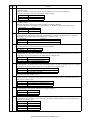
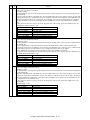
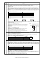
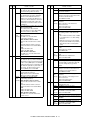
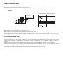
3. High voltage adjustment
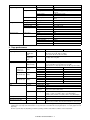
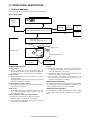
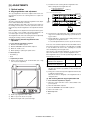
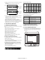
(2) Perform the adjustment in each mode.
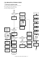
1) Execute SIM 46-1.
2) Select the mode to be adjusted with the exposure mode select
key. Set the exposure level to 3 for all adjustment. (Except for
the auto mode.)
(1)
(2)
Note:
• Use a digital multi meter with internal resistance of 10MΩ or
more measurement.
• After adjusting the grid LOW output, adjust the HIGH output. Do
not reverse the sequence.
Procedures
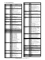
(1) Mode select key/display lamp
(2) Exposure level select key/
display lamp
Adjustment
mode
Auto mode
Manual mode
Photo mode
Manual T/S
mode
Auto T/S mode
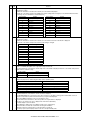
A. Main charger (Grid bias)
Exposure mode
display lamp
Auto lamp ON
Manual lamp ON
Photo lamp ON
Manual lamp/Photo lamp
ON
Auto lamp/Photo lamp ON
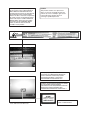
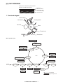
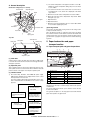
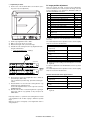
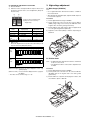
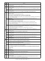
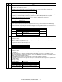
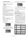
1) Set the digital multi meter range to DC700V.
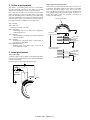
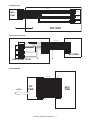
2) Set the positive side of the test rod to the connector CN11-3
(GRID) of high voltage section of the power PWB and set the
negative side to the frame ground (power frame).
Sharp gray chart
adjustment level
"3" is slightly copied.
"3" is slightly copied.
"3" is slightly copied.
"3" is slightly copied.
3) Execute SIM 8-2. (The main charger output is supplied for 30
sec in the grid voltage HIGH output mode.)
4) Adjust the control volume (VRG1) so that the output voltage is
580 ±12V.
"3" is slightly copied.
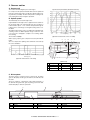
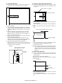
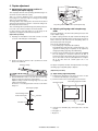
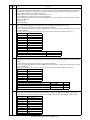
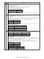
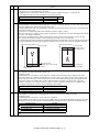
3) Make a copy.
Check the adjustment level (shown in the above table) of the
exposure test chart (Sharp Gray Scale).
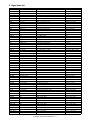
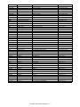
Sharp Gray Scale adjustment level
Non toner
save
mode
1
2
3
4
5
VRG1
6
7
8
9
10
W
6
7
8
9
10
W
Slightly copied.
Not copied.
Toner
save
mode
1
2
3
4
5
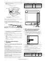
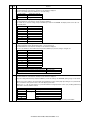
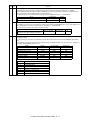
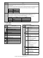
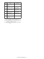
B. DV bias check
Note: • A digital multi meter with internal resistance of 1GΩ must
be use for correct check.
• The adjustment volume is locked, and no adjustment can
be made.
Slightly copied.
Not copied.
(When too bright): Decrease the value displayed on the copy
quantity display.
Procedures
(When too dark):
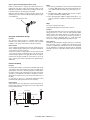
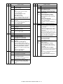
2) Set the positive side of the test rod to the connector CN-10-1
(DV BIAS) and set the negative side to the frame ground
(power frame).
Increase the value displayed on the copy quantity display.
∗ The value can be set in the range of 1 - 99.
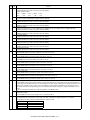
1) Set the digital multi meter range to DC500V.
3) Execute SIM 8-1 to output the developing bias for 30sec, and
check that the output is –400 ± 8V.
VRDV
AL-2040CS ADJUSTMENTS 9 - 5