1
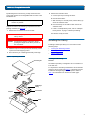
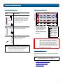
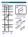
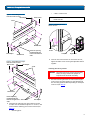
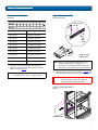
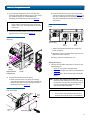
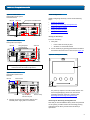
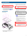
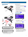
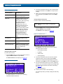
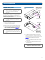
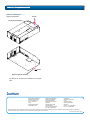
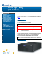
PX502 Tape Library
Quick Start Guide
TABLE OF CONTENTS
Introduction .......................................1
Notational Conventions .................1
Choosing a Location ..........................2
Rack Space Requirements...............2
Introduction
0
The PX502 tape library is an automated storage and retrieval device consisting of
up to two tape drives and up to 32 SDLT cartridges or 38 LTO tape cartridges (see
figure 1).
Environmental Conditions .............2
Preparing for the Installation ...........2
Providing Necessary Tools ..............2
Taking ESD Precautions ..................2
Unpacking the PX502 Tape Library ...2
Removing the Remaining Packing
Materials.............................................9
Notational Conventions
0
This instruction uses the following conventions:
NOTE: Notes emphasize important information related to the main topic.
Installing the Library .........................3
Locating the Mounting Position ....3
Installing the Library ......................4
CAUTION:
Cautions indicate potential hazards to equipment and are included
to prevent damage to equipment.
Initial Configuration .......................9
Multiple Library Stacks....................13
WARNING: Warnings indicate potential hazards to personal safety and are
included to prevent injury.
This document explains how to unpack the PX502 tape library and install it in a
standard 19 in. rack. Once the library is unpacked and installed, set up the library
using the instructions in the PX500 Series User’s Guide PN 81-81290. This
installation procedure will take approximately 4 hours to complete.
NOTE: It is recommended to review the entire document prior to beginning the
installation.
Figure 1 PX502 Tape Library
PX502 Tape Library Quick Start Guide
Choosing a Location
0
Rack Space Requirements
•
Environmental Conditions
Rack Space Requirements
0
Provide the following tools for unpacking and installing the
PX502 tape library:
When choosing an installation site for the PX502, consider
the following requirements:
•
Providing Necessary Tools
0
•
#1 PHILLIPS® screwdriver
•
#2 PHILLIPS screwdriver
•
#1 flat blade screwdriver
•
Allen wrench (2.5mm and 3mm) included in accessory
kit
•
Antistatic wrist strap included in accessory kit
Table 1 contains the rack requirements for the PX502 tape
library.
Taking ESD Precautions
Some components within the PX502 tape library contain
static-sensitive parts. To avoid damaging these parts while
performing installation procedures, always observe the
following precautions:
Table 1 Rack Requirements
Dimensions
PX502
Depth
31 in (78.7 cm)
Width
19 in (48.3 cm)
Height
6.75 in (17 cm), 4U
Weight
52 lbs (23.6 kg)
Air Clearance
Open 4 in (10 cm) behind unit
for proper air flow
Environmental Conditions
•
Humidity: 20%-80% non-condensing
•
Temperature: 10°C-35°C (50°F-95°F)
•
Altitude: -500 to 10,000 feet (-152 to 3048 meters)
These environmental conditions apply when the PX502 tape
library is in operation.
NOTE: For additional specifications, refer to the
Quantum PX500 Series User’s Guide (PN 8181290)
Preparing for the Installation
Before you begin the installation procedure in this section,
make the following preparations as described in this
section:
Providing Necessary Tools
•
Taking ESD Precautions
•
Keep the PX502 turned off during all installation
procedures.
•
Use an antistatic wrist strap (included in the accessory
kit).
•
Keep static-sensitive parts in their original shipping
containers until ready for installation. Look for the ESD
sticker to identify static sensitive parts.
•
Avoid touching connectors and other components.
0
The installation site must have the following environmental
conditions:
•
0
NOTE: Dry climates and cold-weather heating
environments have lower relative humidity and
are more likely to produce static electricity.
Unpacking the PX502 Tape Library
0
This section explains how to unpack the PX502 tape library
and move it to its final installation location.
0
NOTE: Inspect the outer library packaging for damage. If
there is any damage evident on the library
packaging, do not continue with the installation
and contact Quantum customer support.
2
PX502 Tape Library Quick Start Guide
4 Remove the antistatic sheet:
By following these instructions, you help ensure that the
system will continue to be safeguarded after it arrives at the
installation site.
a Cut the tape strips securing the sheet.
b Fold the sheet down.
NOTE: Unpack the library as close to the installation
location as possible.
c With the help of a second person, lift the library up
off of the antistatic sheet.
d Place the library on the table or desk next to the
antistatic sheet.
Unpack and remove the following components from the
packing materials (see figure 2):
e If this is a multiple library stack, refer to “Multiple
Library Stacks” on page 13 before proceeding.
1 Remove the accessories kit and set it aside.
The PX502 is ready to install.
WARNING: At least two people are required to move the
library chassis.
CAUTION:
Lift the library chassis at the sides. Avoid
putting the weight of the library chassis on
the front bezel.
Installing the Library
0
Installing a PX502 tape library in a rack consists of the
following steps:
2 With the help of a second person, lift the library chassis
up and out of the shipping carton.
•
Locating the Mounting Position
•
Installing the Library
3 Place the library on a table approximately waist high.
•
Initial Configuration
Figure 2 Unpacking the PX502
Accessory kit
Locating the Mounting
Position
0
The PX502 tape library is designed to fit in a standard 19
inch wide rack.
It is important to the library installation to locate the hole
pattern in the rack rails (see figure 3). The library must be
installed at the beginning of the hole pattern. Refer to
table 2 for information on common rack hole types.
Foam
PX502 tape
library
Front bezel
Lift point
Foam
3
PX502 Tape Library Quick Start Guide
Table 2 Rack Hole Types
Front panel screws
mounting positions
Description
Cage nut
1 PX502 System (4U)
Figure
Figure 3 Rail Hole Pattern
Square rack holes are the most
common type of rack holes. They
can accept either cage nuts which
mount from the back of the rail or
clip nuts which clip on from the
side of the rack rail.
4U
Back panel screws
mounting positions
Front panel screws
mounting positions
1U = 1.75 in
(44.45mm)
Clip nut
Clip nut
The marks above (X)
indicate the location of
mounting hardware on the
rack rails. Ensure that any
necessary mounting
hardware is installed on the
rack rails prior to installing
the chassis.
Through holes require clip nuts to
accept mounting hardware.
Threaded holes require neither
cage or clip nuts to accept
mounting hardware.
Hole pattern
Top of rack
.312 in (7.92 mm)
.625 in (15.9 mm)
.625 in (15.9 mm)
.5 in (12.7 mm)
.625 in (15.9 mm)
.625 in (15.9 mm)
.5 in (12.7 mm)
WARNING: If the rack is empty at the time of installation,
do NOT install the PX502 tape library too
high in the rack. The weight of the library
may cause the rack to become “top heavy”
and unstable if installed in the top of an
empty rack. Begin installing the PX502 tape
library from the bottom of the rack if more
than one library is installed.
NOTE: The rails within the rack have a hole pattern that
repeats throughout the rail. X marks the screw
positions. Install nut clips (included in the
accessory kit) on the rails if necessary.
Installing the Library
0
Installing the PX502 tape library consists of the following
steps:
NOTE: If this is an upgrade to an existing library system,
see “Multiple Library Stacks” on page 13.
•
Installing the Rack Mount Shelves
•
Installing the Library Chassis
•
Cabling the Library
4
PX502 Tape Library Quick Start Guide
a Loosely attach the adjustable shelves (right and left)
with 4 M5 x 10 Allen screws and T-nuts.
Table 3 Library Mounting Hardware
Qty
Figure
NOTE: T-Nuts must be oriented so they fit in the grooves
of the shelves.
Description
16
Allen head screws (M5
x 10) for shelf
assembly
8
T- nuts (M5)
4 metric
and 4
standard
Rail adapters (both
metric and standard
holes are included, 8
total adapters, see
figure 4)
2
Right and left support
shelves (left shown)
b Attach the appropriate rail adapter to the front and
back of the rack mount shelves (right and left) with 4
M5 x 10 Allen screws (each rail adapter is marked
with the specific hole type supported, either metric
or standard). The rail adapters have arrows
indicating the proper orientation (see figure 4).
Figure 4 Rail Adapter Orientation
4 sets
Front and back rail
mounting hardware
(M5 x 12 allen screws
and mounting plates)
2 sets
Back bracket
hardware (M5 x 8
allen screws and
mounting plate)
2 sets
Back clamp hardware
(M5 x 10 and back
clamp)
Installing the Rack Mount Shelves
Keep the arrow up for
correct orientation
0
1 Assemble the rack mount shelves by (see figure 5 and
figure 6):
5
PX502 Tape Library Quick Start Guide
•
Figure 5 Assembling the LeftHand Rack Mount Shelf
Rail adapter
Allen screws
T-nuts
2 M4 x 12 Allen screw.
NOTE: The rack mount shelves must be installed on the
inside rack rails.
Figure 7 Installing the Rack
Mount Shelves
ft s
Le
lf
he
Allen screws
FlexLink™ opening
located towards the
front for the left-hand
shelf
Rail adapter
Allen screws
Mounting
plate
Allen
screws
Left shelf
Right shelf
3 Once the rack mount shelves are secured to the rack,
tighten the Allen screws securing the adjustable shelves
together.
Figure 6 Assembling the RightHand Rack Mount Shelf
Rail adapter
Allen screws
T-nuts
Installing the Library Chassis
0
WARNING: The PX502 tape library weighs approximately
52 lbs (23.6 kg). At least two people are
required to lift and install the library.
1 The back mounting brackets are lettered (A through I)
so the correct mounting position is easily determined.
The mounting positions differ depending on the depth
of the rack (see table 4).
Ri
gh
Allen screws
FlexLink opening
located towards the
back for the right-hand
shelf
ts
he
lf
Allen screws
Rail adapter
2 Install the left and right rack mount shelves into the
rack (the rack mount shelves adjust 27 in. to 36 in.) and
secure with the following parts in four locations (see
figure 7):
•
Mounting plate
6
PX502 Tape Library Quick Start Guide
Table 4 Back Mounting Bracket
Orientation
Figure 8 Installing the Back
Mounting Brackets
Back mounting
bracket
Rack Depth
Mounting Position
> 27 to 28 in.
Use holes A and C
> 28 to 29 in.
Use holes B and D
> 29 to 30 in.
Use holes A and C
> 30 to 31 in.
Use holes B and D
> 31 to 32 in.
Use holes C and E
> 32 to 33 in.
Use holes D and F
> 33 to 34 in.
Use holes E and G
> 34 to 35 in.
Use holes F and H
> 35 to 36 in.
Use holes G and I
Once the location is determined, attach the back
brackets to each side of the library with four M5 x 8
Allen screws (see figure 8).
NOTE: Use the shortest depth number. For example, if
the measurement is 34 in., use holes E and G.
Allen
screws
Right-hand back
bracket shown.
NOTE: If this is a multiple stack configuration, refer to
“Multiple Library Stacks” on page 13 for
information on preparing the library chassis for
passing tape cartridges from one unit to another.
2 Install the library into the rack as shown in figure 9 and
secure the library to the rack with four PHILLIPS screws.
WARNING: The PX502 tape library weighs approximately
52 lbs (23.6 kg). At least two people are
required to lift and install the library.
Figure 9 Installing the PX502 in
the Rack
PHILLIPS screws
7
PX502 Tape Library Quick Start Guide
3 Secure the back of the library to the rack with two
mounting clamps and two Allen screws on each clamp.
The mounting clamps are oriented differently
depending on the depth of the rack (see figure 10).
NOTE: If the rack depth is 27 to 30 in., the long portion
of the clamp is mounted to the back. If the rack
depth is 30 to 36 in., the long portion is mounted
to the front.
b Insert the tape drive(s) into the drive bay(s) slowly
until the connectors are seated. Refer to figure 12 for
drive bay numbering (see the Quantum PX500 Series
Tape Drive Installation Instructions PN 81-81301 for
information).
Figure 12 Installing the Tape
Drives
4 Secure the mounting clamps to the rack rails with two
PHILLIPS screws on each side (see figure 10).
Figure 10 Securing the Back of
the Library
Back of Library
Tape
drive 2
Tape
drive 1
c Tighten the tape drive thumbscrews using a flat
blade screwdriver.
d Repeat these steps to install another tape drive in a
different location, if desired.
The library chassis is installed in the rack.
Cabling the Library
0
1 Connect the SCSI cables and jumpers as shown in the
following figures:
Long
portion
Right-hand back
bracket shown.
Allen
screws
•
Figure 13 SCSI System Controller Board
•
Figure 14 Surrogate SCSI System Controller Board
•
Figure 15 Native Fibre Channel System Controller
Board
5 To install the tape drives into the library:
a Remove the tape drive cover plates (if necessary,
some libraries ship with one tape drive installed) by
loosening the captive screws securing the plate to
the library chassis (see figure 11).
Figure 11 Removing the Tape
Drive Cover Plates
NOTE: SCSI cable lengths should not exceed:
Tape
drive
bay 1
Tape drive
bay 2
NOTE: Quantum ships sufficient SCSI cables and
terminators with the libraries to set up two-drives
per SCSI bus. One tape drive per SCSI bus may be
necessary for optimum performance. Refer to
your tape drive documentation.
•
39.37 feet (12 meters) between the host and
the library for single drive per bus installations.
Cover plate
8
PX502 Tape Library Quick Start Guide
Figure 13 PX502 Cable
Configuration (SCSI System
Controller Board)
Ethernet
Initial Configuration
SCSI System Controller Board
SCSI host
Tape drive 2
Tape drive 1
Back of Library
Power
Initially configuring the library consists of the following
steps:
•
Turning on the Library
•
Removing the Remaining Packing Materials
•
Setting the Library Options
•
Setting the Date and Time
•
Setting Network Information
Turning on the Library
0
To turn on the library:
Figure 14 PX502 Cable
Configuration (Surrogate)
Ethernet
0
1 Verify that:
SCSI host
Surrogate System
Controller Board
•
Power cables are firmly in place
•
All doors are closed and latched
2 Turn on the library by pushing power button located on
the bottom left-hand corner of the OCP (see figure 16).
Tape drive 2
Tape drive 1
Figure 16 Turning on the Library
Back of Library
Power
NOTE: When operating in surrogate mode, the SCSI host
connection must be made to tape drive 1.
OCP
Figure 15 PX502 Cable
Configuration (Native Fibre
Channel)
Ethernet
Fibre Channel
host/SAN
Tape drive 2
Power
Tape drive 1
Tape Drive Fibre
Channel host ports
Back of Library
2 Connect one end of an AC power cable to each
installed power supply and to a wall outlet.
Power button
The power up sequence can take several minutes. The
first message displaying will be “Are the internal
packaging materials removed?” Continue with
Removing the Remaining Packing Materials
Removing the Remaining Packing Materials
0
Now that you have installed the library chassis and powered
on the system, you MUST remove the remaining packing
materials from the library chassis before the library is
operational.
9
PX502 Tape Library Quick Start Guide
1 Put on an antistatic wrist strap and clip it to the library
chassis.
CAUTION:
Take standard ESD precautions when
performing this procedure.
2 IF there is space above the library to remove the top
cover, remove the twelve PHILLIPS screws securing the
top cover and FlexLink cover to gain further access to
the internal packaging restraints (see figure 17). If there
is no space above the PX502 library to remove the top
cover, continue with Step 3.
Figure 17 Removing the Top
Cover (Optional Step)
4 Press NO to continue. The system asks you again: “Are
the internal packaging materials removed?” (OK or
NO).
CAUTION:
Pressing OK when the internal packaging
restraints are in place will damage the library
robotics.
5 Press NO to continue. The OCP displays “Doors opened,
magazines released, pull magazines out before power
shutoff. The library waits approximately 30 seconds for
you to open the doors and remove both magazines
from the library.
NOTE: If you are unable to remove the magazines before
the library shuts down. Turn on the library power
and repeat the steps above.
6 After the library has powered down, remove the foam
restraints by completing the following steps (see
figure 18):
a Detach the tie band holding the two sides of the
metal restraints together and remove it from the
library.
b Remove the metal restraints from the library.
c Lift the left foam restraint slightly up and remove it
from the library.
d Slide the right foam restraint to the right until you
are clear of the robotics motor and remove the
restraint from the library.
CAUTION:
Avoid touching the printed circuit board.
CAUTION:
When removing the foam restraints, ensure
that the robotics umbilical cable is lying
down in the correct position and not across
the robotics track.
3 When the library powers on for the first time, the OCP
asks you: “Are the internal packaging materials
removed?” (OK or NO).
10
PX502 Tape Library Quick Start Guide
Setting the Library Options
Figure 18 Removing the Foam
Restraints
0
To set the library options:
1 Turn on the library by pushing power button located on
the bottom left-hand corner of the OCP (see figure 16).
2 The OCP asks you: “Are the internal packaging materials
removed?” (OK or NO).
3 Press OK to continue.
4 The OCP asks again: “Are the internal packaging
materials removed?” (OK or NO).
5 Press OK to continue. The library continues the boot
process. When complete, the Home screen displays.
Tie band
6 Press Setup from the Home screen. The OCP displays
the Setup screen (see figure 19):
Figure 19 Setup Screen
Metal
restraint
Enter
7 From the Setup screen, use the up and down arrows to
highlight Cabinet and press Enter.
The Cabinet screen displays (see figure 20):
Foam
restraints
Metal
restraint
Figure 20 Library Options Screen
Robotics
umbilical
cable
NOTE: Save the robotics restraints and re-usable tie wrap
for later shipping or relocation of the library.
e Install the tape cartridge magazines.
NOTE: Refer to the PX500 Series User’s Guide (PN 8181290) for more information on loading the tape
cartridge magazines.
8 The Stack role screen allows you to configure the
library as a “Master” or “Slave” in a multiple library
stack. The library is configured “Solo” by default. If this
is a multiple library stack, use the up and down arrows
to highlight Stack role and press Enter displays the
following information about the library:
f Close the front doors.
g If you have removed the top cover for better access,
install the top cover back on the library.
11
PX502 Tape Library Quick Start Guide
2 Use the up and down arrows to view or edit the date
and time information. Press Enter to accept the new
settings.
Table 5 Setting Up the Cabinet
Cabinet Options
Description
Host bus
Sets the SCSI ID for both the
library and tape drives.
Stack role
Assigns the library stack role
as Master, Slave, or Stand
alone (solo). There can be only
one Master library in a
multiple stack. Once
configured as a slave, all
library OCP functions can be
controlled via the Master
library OCP. The library model
number will also change to
PX500S indicating a stacked
library configuration. The
library model number is
available from the home
screen on the Master library
OCP.
Left load port
Enables or disables the left
load port
Right load port
Enables or disables the right
load port
Drive FUP from tape
Allows you to perform a tape
drive firmware update from a
firmware update tape
cartridge.
Setting the Date and Time
3 When you are finished viewing/editing the date and
time information, press Exit to return to the Setup
screen.
Setting Network Information
To view or edit the network information:
NOTE: The library must be offline to change these
settings.
1 From the Setup screen, use the up and down arrows to
highlight Network and press Enter.
The Network screen displays (see figure 22):
Figure 22 Network Screen
The Network screen allows you to view or edit the
following network settings:
0
To set the date and time:
1 From the Setup screen, use the up and down arrows to
highlight Date and Time and press Enter.
The Date and Time screen displays (see figure 21):
Figure 21 Date and Time Screen
0
•
DHCP (default setting)
•
IP address
•
Subnet mask
•
Default gateway
2 Use the up and down arrows to select the network
setting you wish to view or edit and press Enter.
When you are finished viewing/editing the network
information, press Back to return to the Setup screen.
3 For the network information such as the IP address to
be active, you must reboot the library by holding down
the power button located on the front of the library
(see figure 16).
The library shuts down.
4 Push the power button to start the library.
The PX502 tape library is initially configured and ready
for use.
The Date and Time screen displays the following
information about the library:
12
PX502 Tape Library Quick Start Guide
Multiple Library Stacks
0
Figure 23 Removing the FlexLink
Cover
NOTE: If the library is NOT being installed with other
libraries to operate in a multiple library stack, it is
not necessary to complete the following
instructions.
Remove only the top
FlexLink cover on the
bottom library in the
stack
Screws
p
To
If the library will be installed in a rack with other PX500
Series libraries, you must prepare each chassis prior to
installation. Preparing the library chassis for installation into
a multiple library stack consists of:
FlexLink cover
NOTE: It is recommended to place the Master library in
the middle of the library stack for improved
performance.
•
Removing the FlexLink cover plates
•
Installing the alignment hardware
FlexLink cover
To prepare the library chassis for multiple stack operation:
1 Remove two PHILLIPS screws securing each FlexLink
cover located on the top and bottom of the library
using a #1 PHILLIPS screwdriver (see figure 23).
NOTE: Remove the bottom FlexLink cover on every library
except the bottom library in the stack. Remove
the top FlexLink cover on the bottom library in the
stack.
Bo
m
tto
Screws
Remove only the
bottom FlexLink
cover on the top
library in the stack
2 The alignment hardware installed on the top and
bottom of the libraries in a multiple stack allow the
FlexLink bays to align correctly when installed in a rack.
Install the following alignment hardware (see
figure 24):
a Install the top alignment hardware with two Allen
head screws.
b Install the bottom alignment hardware with one
Allen head screw.
NOTE: Install only the bottom alignment hardware on
the top library in the stack and the top alignment
hardware on the bottom library in the stack.
13
PX502 Tape Library Quick Start Guide
Figure 24 Installing the
Alignment Hardware
Screws
Top alignment hardware
p
To
tto
Bo
m
Screws
Bottom alignment hardware
The libraries are prepared for installation in a multiple
stack.
United States of America
Quantum Corporation
141 Innovation Drive
Irvine, CA 92612
U.S.A.
phone 949.856.7800
fax 949.856.7799
European Headquarters
Quantum Corporaton
3 Bracknell Beeches
Old Bracknell Lane West
Bracknell
Berkshire RG12 7BW
United Kingdom
phone +44 1344 353500
fax +44 1344 353510
Asia Pacific
Quantum Corporaton
Level 3
200 Creek Street
Brisbane, Qld 4000
Australia
phone +61 7 3839 0950
fax +61 7 3839 0955
©2006 Quantum Corporation. Quantum, the Quantum logo, and the DLTtape logo are all registered trademarks of Quantum Corporation. SDLT and Super DLTtape are trademarks of
Quantum Corporation. Other trademarks may be mentioned herein which belong to other companies.
81-81292-02 A01 January 2006