1
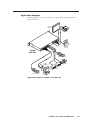
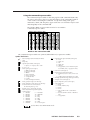
Equipment following the SCART interconnection standard may be
connected using the RGBcS input cabling configuration.
4
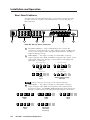
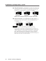
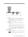
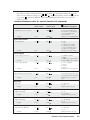
S-video/Composite video inputs — Connect an S-video or composite video
signal to the appropriate female BNC connector(s), as shown here.
Y
/VID
Y
/VID
C
C
S-video
input
Composite video
input
5
SDI (serial digital interface) input connector — Connect an SDI signal to
this female BNC connector.
Only DVS 406 D and DVS 406 AD models have an SDI connector.
6
Output 15-pin HD connector — Connect a display device to this female
VGA-style connector for RGB output.
Both outputs 6 and 7 are buffered and can be connected simultaneously to
two different displays. The sync format will be the same for both outputs.
7
Output BNC connectors — Connect coaxial cables from a display device to
these BNCs for one RGBHV, RGBS, or RGsB/RsGsBs video output as
follows:
R
G
B
H/HV
V
RGBHV
R
G
B
H/HV
V
R
RGsB (Sync on Green)
RsGsBs (output only if input is RsGsBs)
G
B
H/HV
V
RGBS
Both outputs are buffered and can be connected simultaneously to two
different displays. For RGB inputs, the output signal’s sync format is based
on the format of the incoming RGB signal. For all other types of inputs, the
user selects the output sync format. The sync format will be the same for
both outputs.
8
RS-232 port — This connector provides for two-way RS-232
communication. See chapter three, “Serial Communication”, for
information on how to install and use the control software and SIS
commands.
The default protocol is 9600 baud, 1 stop bit, no parity, and no flow control.
The rear panel RS-232 9-pin D connector has the following pin
assignments:
Pin RS-232 function
1
2
3
4
5
6
7
8
9
–
Tx
Rx
–
Gnd
–
–
–
hardwired IR
Description
No connection
Transmit data
Receive data
No connection
Signal ground
No connection
No connection
No connection
IR input
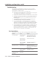
5
1
9
6
DB9 Pin Locations
Female
DVS 406 • Installation and Operation
2-5