1
LESSON 10 – Basic Instructions
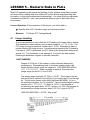
Basic instructions are bit control instructions, typically they make up 90% of the ladder
program. They are used to confirm input status, manipulate outputs, bit shifts, and
master control for nesting contacts.
Lesson Objectives: At the conclusion of this lesson, you will be able to…
9
9
Name the most common basic instructions.
Know the format of the instructions and what they do.
Materials:
FX-Series PLC Training Manual
FX3U Programming Manual – Basic and Applied Instructions
10.1 Symbols
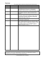
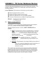
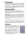
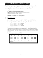
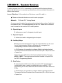
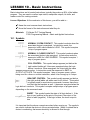
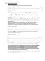
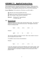
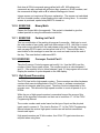
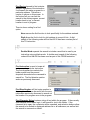
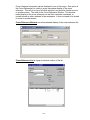
NORMALLY OPEN CONTACT. This symbol conducts when the
associated device is energized. In instruction mode, the
mnemonic is LD, which stands for LOAD. This symbol occupies
1 step of program space.
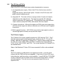
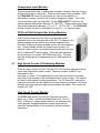
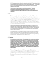
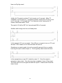
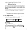
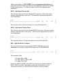
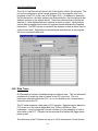
NORMALLY CLOSED CONTACT. This symbol conducts when
the associated device is de-energized. In instruction mode the
mnemonic is LDI, for LOAD INVERSE. This symbol occupies 1
step of program space.
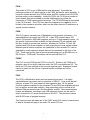
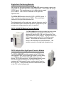
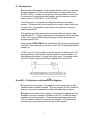
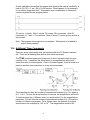
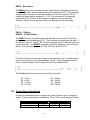
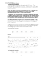
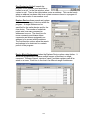
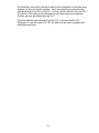
COIL CONTROL. This symbol always appears just before the
right vertical ladder rail. It becomes energized when the logic
before it conducts. When energized, the output with the same
address becomes active. In instruction mode the mnemonic is OUT, for
OUTPUT ACTIVATE. This symbol occupies 1 step of program space, unless
being used for a timer or counter instruction, when it can occupy up to 5 steps.
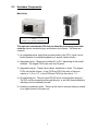
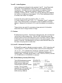
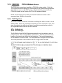
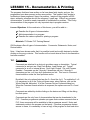
BRACKET CONTROL. This symbol usually appears just before
the right vertical ladder rail when used for bit control. This symbol
is typically used for word device commands; however there are a
few bit instructions that use the brackets as well. It becomes energized when the
logic before it conducts. This symbol occupies multiple steps of program space
depending on the command used.
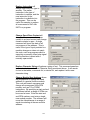
INVERT. This symbol inverts the state of all logic before it. If the
logic is true (positive) at the point of the invert, the output of the
invert is false (negative). If the logic is false, the invert output is
true.
It is important that the above concepts are clear before moving on. The symbols
are used to indicate the device in its non-actuated state. When it’s stated that a
device is conducting, that means electricity is allowed to flow through.
61