1
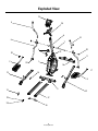
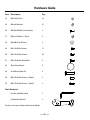
420 Elliptical Trainer
Assembly Manual
Nautilus®
Bowflex®
001-7231-051608A
Schwinn® Fitness
StairMaster®
Universal®
Nautilus Institute®
Table of Contents
Safety Warnings..............................................................................................................................................................3
Exploded View................................................................................................................................................................4
Parts List...........................................................................................................................................................................5
Hardware Guide.......................................................................................................................................................6
Before You Start..............................................................................................................................................................7
Assembly..........................................................................................................................................................................8
Contacts.........................................................................................................................................................................40
2
Assembly Manual
Safety Warnings
This icon means a potentially hazardous situation which, if not avoided, could result in death or
serious injury.
Before using this equipment, obey the following warnings:
Read and understand the complete Owner’s Manual.
Read and understand all Warnings on this machine.
• Keep children away from this machine. Monitor them closely when near the machine. Moving parts that
look dangerous to adults may not look so to children.
• Consult a physician before starting an exercise program. Stop exercising if you feel pain or tightness in
your chest, become short of breath, or feel faint. Contact your doctor before using the machine again.
Use the values calculated or measured by the machine’s computer for reference purposes only.
• Examine this machine for loose parts or signs of wear. Contact Nautilus Customer Service for repair
information.
• Do not wear loose clothing or jewelry. This machine contains moving parts.
• Maximum user weight limit: 300 lb. (136 kg). Do not use if you are over this weight.
• Make the pedals stable before stepping on them. Use caution when stepping off the machine.
• Disconnect all power before servicing this machine.
• Do not operate this machine in damp or wet locations.
• Keep at least 19.5" (0.5 m) on each side of the Elliptical clear. This is the recommended safe distance
for access and passage around and emergency dismounts from the machine.
• Keep the foot pedals clean and dry.
• Do not overexert yourself during exercise. Operate the machine in the manner described in this manual.
• This machine is for home use only.
3
Assembly Manual
Exploded View
19
9
20
6
8
10
7
4
32
21
32
11
2
13
33
1
16
14
3
5
15
22
23
17
18
4
Assembly Manual
12
Parts List
Item Description
Qty
1
2
3
4
5
6
7
8
9
10
11
12
13
14
15
16
17
18
19
20
21
22
23
1
1
1
1
1
1
1
1
1
1
1
1
1
2
1
1
2
1
1
1
1
2
2
Main Frame
Left Foot
Right Foot
Water Bottle Holder
Rear Stabilizer
Console Mast
Arm Pivot Rod
Lower Left Handlebar
Upper Left Handlebar
Upper Right Handlebar
Lower Right Handlebar
Right Leg
Left Leg
Foot Mount Plate
AC Power Adapter
Front Stabilizer
Running Rail
Transport Handle
Console
Static Handlebar
Mast Boot
Threaded Foot Pad
Foot Adjust Nut
A. Compare the Parts List to the box contents. Make sure you have all parts before installing.
B. U
npackage and put all parts near the final location to avoid moving the equipment when fully
assembled.
5
Assembly Manual
Hardware Guide
Item Description
Qty
24
M8 Flat Washers
41
25
M8 Lock Washers 41
26
M5 0.8x25 Phillips Head Screws
2
27
M8 Lock Washers - Black
4
28
M8 Wide Flat Washers
4
29
M8 1.25x15 Hex Screws
17
30
M8 1.25x20 Hex Screws 20
31
M8 1.25x20 Hex Head Bolts
4
32
45mm Round Cover
4
33
Arm Mount Cotter Pin
2
34
M8 1.25x20 Hex Screws - Nylock
2
35
M8 1.25x25 Hex Screws - Nylock
2
Tools Required
Hex Key w/Phillips Head
1
Combination Wrench
2
You may also need a rubber mallet (not included).
6
Assembly Manual
Before You Start
Locate where you will assemble and use your Schwinn® 420 Elliptical Trainer. We recommend you install it on a
hard, level surface. Allow an area of at least 62" L x 50" W (1.57 m x 1.27 m). You need at least 101" L x 66" W (2.57 m
x 1.68 m) of free space for safe operation.
Basic Assembly Principles
Follow these basic assembly tips when putting together your Elliptical Trainer:
1. Collect all the pieces needed for each step before assembling.
2. Turn all bolts and locknuts to the right (clockwise) to tighten, and to the left (counterclockwise) to loosen.
3. When attaching two pieces, lightly lift and look through the bolt holes to help guide bolts through the
holes.
4. Two people are necessary to assemble this machine.
NOTE: Some axles contain oil. Use caution to avoid staining clothes or carpet.
7
Assembly Manual
Assembly
Step 1: Install Rear Stabilizer and Transport Handle
Parts
1-1Attach two Running Rails to Rear Stabilizer with the
hardware shown. Do not tighten.
• #5 - Rear Stabilizer (Qty. 1)
• #17 - Running Rail (Qty. 2)
• #18 - Transport Handle (Qty. 1)
• #22 - Threaded Foot Pad (Qty. 2)
• #23 - Foot Adjust Nut (Qty. 2)
1-2Attach the Transport Handle to each Running Rail with 2
Foot Adjust Nuts and 2 Foot Pads.
1-3Fully tighten all hardware.
Hardware
• #24 - M8 Flat Washer (Qty. 8)
• #25 - M8 Lock Washer (Qty. 8)
• #29 - M8x15 Hex Screw (Qty. 8)
Tools
• Hex Key
5
17
25
23
18
22
8
Assembly Manual
24
29
Assembly
Step 2: Install Front Stabilizer
Parts
2-1 Attach the Main Frame to the Front Stabilizer with the
hardware shown.
• Rear Stabilizer assembly (from Step 1)
• #1 - Main Frame (Qty. 1)
• #16 - Front Stabilizer (Qty. 1)
2-2Attach the Main Frame to the Rear Stabilizer with the
hardware shown.
2-3Adjust the 6 Foot Pads (A) under the Stabilizers and
the Transport Handle until they just touch the floor (see
Figure 2a). First, twist the Threaded Foot Pad out and
then lock with the Foot Adjust Nut to keep machine
stable.
Hardware
• #24 - M8 Flat Washer (Qty. 8)
• #25 - M8 Lock Washer (Qty. 8)
• #30 - M8x20 Hex Screw (Qty. 8)
Tools
• Hex Key
1
Figure 2
30
25
24
16
24
30 25
Figure 2a
A
9
Assembly Manual
Assembly
Step 3: Install Console Mast and Water Bottle Holder
Parts
3-1 Put the Console Mast into the Mast Boot.
• Main Unit (from Step 2)
• #4 - Water Bottle Holder
(Two parts: (4a) outer ring, (4b) - base)
• #6 - Console Mast (Qty. 1)
• #21 - Mast Boot (Qty. 1)
3-2 Connect the wire harness (W1) from the Main Unit to the
wire harness (W2) in the Console Mast.
3-3Move the Console Mast down on the Main Unit. Secure
the Console Mast with the hardware shown.
NOTICE: Do not pinch the wires when putting the
Console Mast on the Main Unit.
Hardware
•
•
•
•
3-4 Move the Mast Boot down to the Main Unit.
#24 - M8 Flat Washer (Qty. 5)
#25 - M8 Lock Washer (Qty. 5)
#26 - M5x25 Phillips Head Screw (Qty. 2)
#29 - M8x15 Hex Screw (Qty. 5)
3-5 Attach the Water Bottle Holder to the Console Mast with
the hardware shown.
Tools
• Phillips Head Screwdriver
6
4a
24
4b
26
25
29
W2
21
W1
10
Assembly Manual
Assembly
Step 4: Install Static Handlebar and Console
Parts
4-1 Feed the Heart Rate Wire (W3) from the Static Handlebar
through the rectangular opening in the handlebar.
• Main Unit (from Step 3)
• #19 - Console (Qty. 1)
4-2 Put the Console Mast Wire (W2) through the rectangular
opening in the Static Handlebar. The Heart Rate Wire
goes through the notch (N) in the Console Mast. Connect
the Static Handlebar to the Console Mast with the
hardware shown.
• #20 - Static Handlebar (Qty. 1)
Hardware
•
•
•
•
#24 - M8 Flat Washer (Qty. 4)
#25 - M8 Lock Washer (Qty. 4)
#30 - M8x20 Hex Screw (Qty. 4)
Pre-installed Screws in Back of Console (Qty. 4)
NOTICE: Do not pinch the wires when putting the
Static Handlebar on the Console Mast.
4-3 Remove the 4 pre-installed screws (S) in the back of the
Console. Save them for Step 4-5.
Tools
4-4 Connect the Console Wire (W4) to the Console Mast
Wire (W2). Connect the Heart Rate Wire to the Heart
Rate connector (W5) from the back of the Console.
• Phillips Head Screwdriver
4-5Attach the Console to the Static Handlebar assembly
with the screws from Step 4-3.
NOTICE: Do not pinch the wires when putting the
Console on the Static Handlebar.
W5
19
W4
W3
S
W2
20
24
25
30
N
11
Assembly Manual
Assembly
Step 5: Install Legs
Parts
Do steps 5-1 and 5-2 on one side and then again
on the other side.
• Main Unit (from Step 4)
• #12 - Right Leg (Qty. 1)
• #13 - Left Leg (Qty. 1)
5-1 Install the Right Leg to the Main Unit with the hardware
shown. Make sure that the upright pivot (B) is closer to
the center of the machine. Make sure the wheels on
each leg align correctly in the Rails.
Hardware
•
•
•
•
#27 - M8 Lock Washer - Black (Qty. 2)
#28 - M8 Wide Flat Washer (Qty. 2)
#31 - M8x20 Hex Head Bolt (Qty. 2)
#32 - Round Cover (Qty. 2)
5-2 Put a Round Cover over the head of each screw.
Tools
• Hex Key
32
31 27
28
13
B
12
Assembly Manual
12
Assembly
Step 6: Install Lower Arms
Parts
Do steps 6-1 and 6-2 on one side and then again
on the other side.
• Main Unit (from Step 5)
• #7 - Arm Pivot Rod (Qty. 1)
• #8 - Lower Left Arm (Qty. 1)
6-1 Move the Arm Pivot Rod through the Console Mast as
shown.
6-2Connect the Lower Right Arm to the Arm Pivot Rod with
the hardware shown. Do not tighten.
• #11 - Lower Right Arm (Qty. 1)
Hardware
• #25 - M8 Lock Washer (Qty. 2)
• #28 - M8 Wide Washer (Qty. 2)
• #31 - M8x20 Hex Head Bolt (Qty. 2)
7
28
25
8
11
13
Assembly Manual
31
Assembly
Step 7: Install Feet
Parts
Do steps 7-1 thru 7-3 on one side and then again
on the other side.
• Main Unit (from Step 6)
• #2 - Left Foot (Qty. 1)
• #3 - Right Foot (Qty. 1)
7-1 Move the shaft under the pedal into the pivot on the
Leg Assembly. Align a Foot Mount Plate with the pivot
and the Foot Assembly. Attach with three M8 Locking
Washers, three M8 Flat Washers, two M8x15 Hex
Screws (outside holes), and one M8x20 Hex Screw
(center hole).
• #14 - Foot Mount Plate (Qty. 1)
Hardware
•
•
•
•
•
•
•
#24 - M8 Flat Washer (Qty. 8)
#25 - M8 Lock Washer (Qty. 8)
#29 - M8x15 Hex Screw (Qty. 4)
#32 - Round Cover (Qty. 2)
#33 - Cotter Pin (Qty. 2)
#34 - M8x20 Hex Screw - Nylock (Qty. 2)
#35 - M8x25 Hex Screw - Nylock (Qty. 2)
7-2 Set the Foot Assembly in the U-bracket at the bottom of
the Lower Handlebar. Put a Cotter Pin from the inside
through the U-bracket and Foot assembly. Attach
with M8x25 Hex Screw, M8 Lock Washer, and M8 Flat
Washer.
NOTE: Make sure the key on the Cotter Pin engages
the slot in the U-bracket.
7-3Tighten the screws holding the arms and then put a
Round Cover over the head of each screw.
Tools
• Phillips Head Screwdriver
• Combination Wrench (Qty. 2)
7-4 Fully tighten all hardware in Steps 6 and 7.
32
2
33
24
14
24
35
34
25
25
29
3
14
Assembly Manual
Assembly
Step 8: Install Moving Handlebars
Parts
Do steps 8-1 thru 8-2 on one side and then again
on the other side.
• Main Unit (from Step 7)
• #9 - Upper Left Handlebar (Qty. 1)
• #10 - Upper Right Handlebar (Qty. 1)
8-1 Put the Upper Right Handlebar into the Lower Right
Handlebar (Figure 8). Make sure that the Upper
Handlebar curves toward the back of the machine
(Figure 8A).
Hardware
• #24 - M8 Flat Washer (Qty. 8)
• #25 - M8 Lock Washer (Qty. 8)
• #30 - M8x20 Hex Screw (Qty. 8)
8-2 Attach with the hardware shown.
Tools
• Hex Key
Figure 8
9
10
30
25
24
Figure 8a
15
Assembly Manual
Assembly
Step 9: Connect Power Cable
Parts
9-1 Find the power connector on the front of the machine
above the Front Stabilizer.
• Main Unit (from Step 8)
• #15 - AC Power Adapter (Qty. 1)
9-2 Connect the AC Power Adapter to the power connector
on the front of the machine.
15
16
Assembly Manual
Assembly
Step 10: Final Check
Failure to visually check and test assembly
before use can cause damage to the equipment.
It can also cause serious injury to users and
bystanders.
10-1Tighten all hardware.
10-2Make sure that the machine is level. If necessary,
adjust the Feet again as described in Step 2.
10-3Read warnings on machine.
Refer to the Owner’s Manual for:
• Operating Instructions
• Maintenance Instructions
17
Assembly Manual
Assembly
18
Assembly Manual
Contacts
UNITED STATES OFFICES
INTERNATIONAL OFFICES
E-mail: [email protected]
For technical assistance and a list of distributors in your
area, please call or fax one of the following numbers.
TECHNICAL/CUSTOMER SERVICE
Phone: 800-NAUTILUS (800-628-8458)
Fax: (877) 686-6466
E-mail: [email protected]
INTERNATIONAL CUSTOMER SERVICE
Nautilus International S.A.
Rue Jean Prouvé
1762 Givisiez / Switzerland
Tel: + 41 26 460 77 77
Fax: + 41 26 460 77 70
E-mail: [email protected]
CORPORATE HEADQUARTERS
Nautilus, Inc.
World Headquarters
16400 SE Nautilus Drive
Vancouver, Washington, USA 98683
Phone: (800) NAUTILUS (800) 628-8458
GERMANY and AUSTRIA
Nautilus Deutschland GmbH
Albin-Köbis-Str. 4
51147 Köln
Tel: + 49 02203 2020 0
Fax: + 49 02203 2020 45 45
ITALY
Nautilus Italy S.r.l., Via della Mercanzia, 103
40050 Funo di Argelato - Bologna
Tel: + 39 051 664 6201
Fax: + 39 051 664 7461
SwITZERLAND
Nautilus Switzerland SA
Rue Jean-Prouvé 6
CH-1762 Givisiez
Tel: + 41 26 460 77 66
Fax: + 41 26 460 77 60
United Kingdom
Nautilus UK Ltd
4 Vincent Avenue
Crownhill, Milton Keynes, Bucks, MK8 0AB
Tel: + 44 1908 267 345
Fax: + 44 1908 267 345
chinA
Nautilus (Shanghai) Fitness Co., Ltd.
7A No.728, Yan’an Road (West)
200050 Shanghai, China
Tel: + 86 21 523 707 00
Fax: + 86 21 523 707 09
19
Assembly Manual
©2008. Nautilus, Inc. All rights reserved. Nautilus, the Nautilus Logo, Universal, Bowflex, StairMaster and Nautilus Institute are either registered trademarks or trademarks of Nautilus,
Inc. Schwinn is a registered trademark. All other trademarks are owned by their respective companies. Nautilus, Inc., World Headquarters, 16400 SE Nautilus Drive, Vancouver, WA 98683
1-800-NAUTILUS www.nautilus.com
Printed in China
Nautilus®
Bowflex®
Schwinn® Fitness
StairMaster®
Universal®
Nautilus Institute®