1
AlterPath BladeManager
User Manual
Product Version 1.3.0
Revision No. 7
This document contains proprietary information of Cyclades and is not to be disclosed
or used except in accordance with applicable contracts or agreements.
©
Cyclades Corporation, 2005
We believe the information in this manual is accurate and reliable. However, we assume no
responsibility, financial or otherwise, for any consequences of the use of this product or manual.
This manual is published by Cyclades Corporation, which reserves the right to make improvements
or changes in the products described in this manual as well as to revise this publication at any time
and without notice to any person of such revision or change. All brand and product names
mentioned in this publication are trademarks or registered trademarks of their respective holders.
Cyclades, AlterPath ACS, AlterPath KVM/net, AlterPath Manager E2000, and AlterPath
BladeManager are registered trademarks of Cyclades Corporation.
IBM, IBM BladeCenter and ServeRAID are registered trademarks of IBM Corporation.
Microsoft, Windows 95, 98, XP, ME, NT, and 2K are trademarks of Microsoft Corporation.
UNIX is a trademark of UNIX System Laboratories, Inc.
Linux is a registered trademark of Linus Torvalds.
For latest manual revisions, please refer to Cyclades website on:
http://www.cyclades.com/support/downloads.php
All rights reserved. This document may not, in whole or part, be copied, photocopied, reproduced,
translated, or converted to any electronic or machine-readable form without the prior written
consent of Cyclades Corporation, 3541 Gateway Boulevard, Fremont, CA 94538, USA.
Telephone (510) 771-6100. Fax (510) 771-6200. www.cyclades.com.
Table of Contents
Before You Begin
Audience
Document Organization
Typographical Conventions
Naming Conventions
Chapter 1: Introduction
Connectivity and Capacity
Key Features
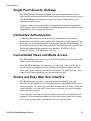
Single Point Security Gateway
Centralized Authentication
Consolidated Views and Blade Access
Simple and Easy Web User Interface
One-Click Access to Blades and Switches
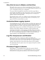
Centralized Data Logging System
Log File Compression and Rotation
Prioritized Triggers & Alarms
Other Alarm Features
Blade Wizard
Chassis, Blades, and User Group
Management
Backup, Restore, and Replicate User Data
Exhaustive Reporting
Multiport Ethernet Cards
Command Line Interface (CLI)
Deploying the BladeManager
i
i
ii
ii
1-2
1-2
1-3
1-3
1-3
1-3
1-4
1-4
1-4
1-4
1-5
1-5
1-5
1-5
1-6
1-6
1-6
1-7
Chapter 2: BladeManager Installation
Product Installation Checklist
Rack Mounting Guidelines
Major Components of the BladeManager
AlterPath Blade Manager Manual
2-1
2-2
2-11
Table of Contents
Installation Safety Guidelines
System Reliability Guidelines
Static-Sensitive Devices
Installation Procedures
Installing DIMMs
Installing a Hard Disk Drive
Installing a Simple-Swap Serial
ATA Hard Disk Drive
Installing a SCSI Hard Drive
Installing an Adapter
2-12
2-12
2-12
2-13
2-13
2-15
Completing the Installation
Connecting the Cables
Updating the Server Configuration
BladeManager Controls, LEDs, and Power
BladeManager Power Features
2-21
2-22
2-23
2-23
2-26
Switching On the Server
Switching Off the BladeManager
Pre-Configuration Requirements
Configuring the COM Port Connection
and Logging In
2-26
2-27
2-28
2-15
2-16
2-17
2-29
Chapter 3: BladeManager Web Access
User Interface Overview
Using the Web Interface as a Regular User
General Screen Features
Sorting a List Form by Column/Field Name
Search and Filter Functions
Alarms
Alarm Logs
Responding to an alarm
Alarm List Form
Viewing the Alarm Detail Form
Viewing Alarm or Console Logs
Assigning a Ticket to a User
II
3-1
3-2
3-4
3-4
3-5
3-5
3-6
3-6
3-6
3-8
3-10
3-10
AlterPath BladeManager Manual
Table of Contents
Blades
Viewing the Blade List
Connecting to a Blade Console
Multiple Users and Read/Write Access
Viewing a Blade or Switch
3-11
3-11
3-13
3-13
3-14
Consoles Detail Form
Consoles Access Form
Consoles Notify Form
Consoles Groups Form
3-14
3-16
3-16
3-17
Logs
Viewing the Logs
Access Logs
Event Logs
Data Buffer
3-18
3-19
3-20
3-21
3-22
User’s Profile
Changing Your Password
Viewing the Use Access Form
Viewing the User Groups Form
Viewing the Security Form
3-23
3-25
3-25
3-25
3-27
Chapter 4: BladeManager Web Administration
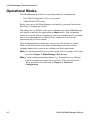
Operational Modes
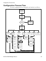
Configuration Process Flow
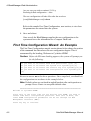
First Time Configuration Wizard
Running the First Time Configuration
Wizard
Resetting Configuration to Factory Settings
First Time Configuration Wizard:
An Example
Setting the Authentication Method
Hostname Configuration Must
Follow RFC Standard
AlterPath BladeManager Manual
4-2
4-3
4-4
4-4
4-5
4-6
4-8
4-8
III
Table of Contents
IV
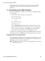
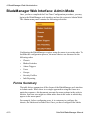
Connecting to the Web Interface
BladeManager Web Interface: Admin Mode
Forms Summary
Logging Into the BladeManager Web Interface
Parts of the Web Interface
Sorting, Filtering, and Saving a List Form
Using the Form Input Fields
Verifying Error Messages
4-9
4-10
4-10
4-14
4-14
4-16
4-17
4-17
Chassis Management
Chassis > Devices List Form
Using a DHCP Server and Selecting the
Correct IP Mode
Function of the Status Field
Selecting the Group(s) to Access a Chassis
4-17
4-19
4-24
4-24
4-25
Proxies
Proxy Types
Configuring the Proxy
Verifying your Proxy Setting
Disabling the Proxy
Configuring Ports to be Proxied
4-26
4-26
4-28
4-29
4-29
4-29
Configuring the Chassis Switch
Two Methods of Blade Configuration
Running the Blade Wizard
Configuring Blades Manually
through the Menu
Consoles List Form
4-29
4-31
4-32
Connecting to a Device
Deleting a Device
Deleting a Device from a Group
Deleting a Device Group
4-38
4-38
4-39
4-39
Alarm Trigger
Alarm Trigger Management
4-39
4-40
4-37
4-37
AlterPath BladeManager Manual
Table of Contents
Viewing the Alarm Trigger List
Creating an Alarm Trigger
Deleting an Alarm Trigger
Using the Logical AND in the
Alarm Trigger Expression
4-40
4-41
4-43
Blades / Switches
Consoles List Form
Viewing the Console List
Adding a Serial Console
Adding a Switch Console
Selecting Users to Access the Console
Selecting Users to be Notified
4-43
4-44
4-45
4-46
4-49
4-49
4-50
Assigning the Console to a Group
Deleting a Console from a Group
Deleting a Console Group
Connecting to a Console
Log Rotation
Initiating Log Rotation
Setting Log Rotation in Auto Mode
4-51
4-52
4-53
4-53
4-53
4-53
4-54
Users
User List form
Adding a User
Selecting Consoles for a User
Selecting User Group(s) for a User
Deleting a User
Deleting a User from a Group
Deleting a User Group
Setting the Local Password
Setting Up Local Authentication
Setting a User’s Security Profile
4-54
4-55
4-55
4-58
4-59
4-60
4-60
4-60
4-61
4-61
4-61
Groups 62
Creating a Group
Deleting a Group
4-62
4-64
AlterPath BladeManager Manual
4-43
V
Table of Contents
Assigning a Security Profile to a User Group 4-64
Security Profiles
Security Profile List
Adding or Editing a Security Profile
Security Profiles: Source IP
Security Profiles: LAN ITF
Security Profile: Date/Time
Configuring Authorization
Deleting a Security Profile
4-65
4-66
4-67
4-68
4-70
4-72
4-73
4-75
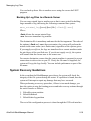
Backing Up User Data
Backup and Restore Scenarios
System Recovery Guidelines
BladeManager Database Transaction Support
Responding to the Warning Message
Changing the Default Configuration
Info / Reporting
4-75
4-76
4-76
4-77
4-77
4-78
4-78
Chapter 5: Advanced Configuration
Working from a CLI
Shell Commands
Copying and Pasting Text within the
Console Applet Window
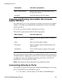
Connecting Directly to Ports
Sample Command Line Interface
Set Commands
Changing the Escape Sequence
Re-defining the Interrupt Key
Changing the Number of Lines in
the SSH Applet
Changing the Session Timeout
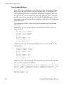
Enabling Telnet
NIS Configuration
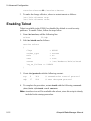
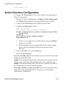
Active Directory Configuration
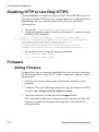
Disabling HTTP to Use Only HTTPS
VI
5-1
5-2
5-2
5-3
5-3
5-5
5-9
5-10
5-11
5-11
5-11
5-12
5-14
5-15
AlterPath BladeManager Manual
Table of Contents
Firmware
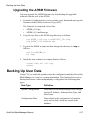
Upgrading the APBM Firmware
Backing Up User Data
Managing Log Files
Changing the Database Configuration
Installing SSL Certificates
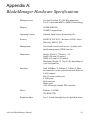
Appendix A: Hardware Specifications
Glossary
AlterPath BladeManager Manual
5-16
5-16
5-17
5-18
5-19
5-20
A-1
VII
Table of Contents
VIII
AlterPath BladeManager Manual
Before You Begin
Welcome to the AlterPath BladeManager Manual! This manual is designed to
help you install, configure, and operate the BladeManager, as well as to guide
you in your daily operations of the product.
Note: For convenience, this document refers to the AlterPath BladeManager
as simply BladeManager or, as in the case of the command line
interface, IPBM.
Audience
This document is designed for system administrators and regular users of the
BladeManager. Users are expected to have basic knowledge of using a
graphical user interface such as Microsoft Windows.
Document Organization
The document is organized as follows:
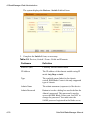
Chapter Title
Description
1: Introduction
Defines and explains the overall
product features and uses of the
BladeManager.
2: BladeManager Installation
Explains the procedure for installing
the BladeManager.
3: BladeManager Web Access
Explains to regular users (as opposed to
admin users) how to use the web user
interface. It highlights such procedures
as connecting to a blade, dealing with
alarms, and other system tracking and
management procedures.
Before You Begin
Chapter Title
Description
4: BladeManager Web
Administration
Explains to the system administrator
how to configure the BladeManager
through the web interface and enable
users to perform the various fault
management procedures such as
connecting to a blade, responding to an
alert and more. Configuration settings
include user access, alarm triggers,
chassis and blade management, security
profiles, as well as running the blade
wizard.
5: Advanced Configuration
Addressed to the advanced user,
provides configuration procedures
using command line interface (CLI). It
includes such procedures as backing up
log files and user data, and installing
SSL certificates.
Typographical Conventions
Form/Window Labels
Words that appear on forms, windows, or any part of the user interface are
typed in boldface.
Examples:
The Alarm Trigger List form; the Password field.
Hypertext Links
With the exception of headings and the Table of Contents (which are already
linked), all underlined words are hypertext links.
Form/Window Levels
Form levels are indicated by the “greater than” symbol (>), starting from the
parent screen to child. Most BladeManager screens or windows contain only
two levels.
Example:
ii
AlterPath BladeManager Manual
Naming Conventions
Blades List > Blade Detail
Naming Conventions
Administrator
Also referred to as the Admin User. The system
administrator of the BladeManager who has
the authority to configure and manage the BladeManager.
BladeManager
The short name for AlterPath BladeManager.
Form
The form is the largest area of the user
interface; it contains the user selection or input
fields for each selected item in the menu.
Form Names
The form names of the application’s GUI do
not necessarily appear on the actual window.
Because some forms do not have titles, these
names are used to distinguish each form as
well as to reflect the form function.
The most commonly used form names are List
forms and Detail forms. The configuration
forms of the BladeManager (i.e., Chassis,
Blades, Users, Alarm Trigger) use the two
types of forms.
Examples:
Blade List form; Blade Definition form.
Regular User
Refers to anyone who uses or logs onto the
BladeManager application as a regular user
(i.e., the web management interface is on
Access mode, not Admin mode) even though
the user may be a system administrator.
Select
To select is the same as to click your mouse.
AlterPath BladeManager Manual
iii
Before You Begin
Command Line Syntax
While this manual is primarily designd for using the BladeManager web
interface, some special features show you how to configure the BladeManager
using the Command Line Interface (CLI). CLI configuration is discussed in
Chapter 5 (Advanced Configuration) of the manual. The typographical
conventions used for showing the syntax for these commands are as follows.
Brackets and Hyphens (dashes)
The brackets ([])indicate that the parameter inside them is optional, meaning
that the command will be accepted if the parameter is not defined. When the
text inside the brackets starts with a dash (-) and/or indicates a list of
characters, the parameter can be one of the letters listed within the brackets.
Example:
iptables [-ADC] chain rule-specification [options]
Ellipses
Ellipses (...) indicate that the latest parameter can be repeated as many times
as needed. Usually this is used to describe a list of subjects.
Example:
ls [OPTION]... [FILE]...
Pipes
The pipe (|) indicates that one of the words separated by this character should
be used in the command.
Example:
netstat {--statistics|-s} [--tcp|-t] [--udp|-u] [--raw|-w]
When a configuration parameter is defined, the Linux command syntax
conventions will be also used, with a difference.
Greater-than and Less-than signs
When the text is encapsulated with the “<>” characters, the meaning of the
text will be considered, not the literal text. When the text is not encapsulated,
the literal text will be considered.
Spacing and Separators
The list of users in the following example must be separated by semicolons
(;); the outlets should be separated by commas (,) to indicate a list or with
iv
AlterPath BladeManager Manual
Command Line Syntax
dashes (-) to indicate range; there should not be any spaces between the
values.
sXX.pmusers: The user access list. For example: jane:1,2;john:3,4. The
format of this field is:
[<username>:<outlet list>][;<username>:<outlet list>...]
Where <outlet list>'s format is:
[<outlet number>|<outlet start>-<outlet end>][,<outlet number>|<outlet
start>-<outlet end>]...
AlterPath BladeManager Manual
v
Before You Begin
vi
AlterPath BladeManager Manual
Chapter 1
Introduction
The AtlerPath BladeManager is a comprehensive in-band and out-of-band
blade management tool designed to complement the IBM Director. It provides
BladeCenter users the necessary security, authentication, access control and
administration capabilities to remotely manage blade servers and switch
modules.
The BladeManager provides a wide range of features which includes the
following:
•
•
•
•
Continuously captures and records data logs for all BladeCenter devices
for diagnostic and audit purposes.
Generates system alarms and user notifications to avoid or reduce system
failures.
Provides secure, remote access to OS, POST and BIOS on every blade
server and switch module to enable administrators to quickly diagnose
and restore disconnected devices.
Easy-to-use web interface for administrators and regular users.
For a summary of all the AlterPath BladeManager features, see “Key
Features” on page 1-2 of this chapter.
The BladeManager web interface provides two modes based on the type of
user:
•
•
Access
Admin
The Access mode is for regular users to view and access the blade servers to
which they have authorized access. The Admin mode is for system
administrators to configure and administer the BladeManager and its users.
Note: Anyone who uses the BladeManager application in Access mode is
referred to as a user, regardless of whether that user is a system
administrator or not. An administrator or admin user is anyone who
has the exclusive authority to configure and to perform various system
administrative tasks for the BladeManager.
1: Introduction
Connectivity and Capacity
The BladeManager hardware platform is based on the IBM eServer xSeries
306. It comes with a Blade Wizard which enables the admin user to create up
to 14 blades and 4 switches for each chassis. The BladeManager supports up
to 6 chassis; altogether, the module support a maximum of 84 blades and 24
switches.
All blades have Serial over LAN (SOL), KVM/IP, virtual media, and power
options created. For security, blade users are controlled by the Control Access
List (ACL) which is configured through the Security Profile settings.
The switches connect as secondary or cascaded devices to the chassis.
Front view of the BladeManager:
See Chapter 2: BladeManager Installation to view the port connections
available from the BladeManager.
Key Features
The key features of AlterPath BladeManager are:
•
•
•
•
•
•
•
•
•
•
•
•
•
•
•
1-2
Single point security gateway
Centralized authentication
Consolidated views
One-click access to consoles and devices
Centralized data logging system
Access log audit trail
Log file compression and rotation capabilities
Prioritized triggers and alarms
Blade wizard
Device, Console, and User Group Management
Backup, restore, and replicate user data
Exhaustive reporting
Convenient web user interface
Easy command line interface
Product maintenance
AlterPath BladeManager Manual
Key Features
Single Point Security Gateway
The BladeManager has been designed such that communication between
users and the management network must pass through a single point of access
(the BladeManager) to optimize security and enforce adherence to your
corporate security policy.
A single, secure access point reduces management overhead for managing
blade servers. Moreover, the multiple authentication options available ensures
compatibility with existing infrastructure.
Centralized Authentication
Centralized authentication saves the user or administrator from using a
password for each blade server, and thereby maintain a secure password. You
need only use your password once upon logging onto the BladeManager. To
access the blade servers and switch modules, the BladeManager provides the
following authentication methods: local database, RADIUS, LDAP,
Kerberos, Tacacs+, NIS and active_directory.
Consolidated Views and Blade Access
The BladeManager provides secure OS, POST and BIOS access to individual
blades and switch modules.
From the BladeManager web interface, you can view a list of all blades to
which you have authorized access. Information about each blade includes
blade name, port, location, description, and status. For added security, users
cannot view blades which they are not authorized to use.
Simple and Easy Web User Interface
The BladeManager provides a convenient and user-friendly web user
interface for the regular user and the administrator. Hyperlinks enable you to
access consoles, view data logs, and other information even faster. From one
single interface, you can achieve just about everything you need to manage
your network’s consoles.
Users can only view and access those blades and switches to which they are
assigned. This customization adds security to the system since users cannot
view or access any blade or switch that does not concern them.
AlterPath BladeManager Manual
1-3
1: Introduction
One-Click Access to Blades and Switches
Placing the mouse cursor over a chassis name from the Chassis List form
allows the system administrator to access the BladeManager through the web
or CLI. The default session type is configurable.
To access a blade, the regular user can choose and click on any blade or
switch listed on the Blades List form. This opens a console session (through
Secure Shell) for that particular blade, allowing the user to remotely fix
problems related to the target blade.
By placing the mouse cursor over a blade or switch console name from the
Blades List form, the user can select KVM, serial over LAN (SOL), or to
power ON/OFF the selected blade or switch.
Centralized Data Logging System
The BladeManager provides continuous online and offline data logging of all
system messages. It captures all console log messages and writes them to its
internal hard disk drive. With a console log capacity of 20GB, the secure
online/offline storage ensures availability of all important console messages.
Each line of the logfile contains a timestamp (a feature which prevents
tampering) and provides a tool for analyses and audit trailing. Each time a
user connects to a blade or switch, BladeManager adds a timestamp to the log
file. The user identification timestamp is recorded in the data buffer and
logged separately on the BladeManager access log database.
Log File Compression and Rotation
When a log file reaches a certain size (which is specified by the
administrator), the system automatically compresses the file and then creates
a new file to collect a new set of console data. The file rotation should be
seamless with no data loss as the system copies from one file to another.
The administrator has the option to move the compressed log file to another
server for archiving.
Prioritized Triggers & Alarms
BladeManager’s event handling feature enables the system to identify
possible issues and alert the user. As the BladeManager sends a message to
the hard disk for storing and consolidation, it also scans the message for
1-4
AlterPath BladeManager Manual
Key Features
triggers. A trigger is a text string pre-defined by the administrator which the
system uses to detect a trigger text from messages. When the BladeManager
detects a trigger text, based on how the trigger was configured by the
administrator, it does the following:
•
•
•
Send an email to a user list
Create a prioritized alarm entry in the Alarm database
Write a log message to the BladeManager logging system to acknowledge
the trigger.
Other Alarm Features
•
•
Notes - You can add notes to an alarm to indicate what action you have
taken. These notes can be useful for future reference to similar issues.
Reports - You can generate a report to show what actions were taken by
whom, and how long it took to fix the issue.
Blade Wizard
The blade wizard allows the system administrator to define the blades
automatically using default and customized values. The wizard automatically
configures the selected blade(s) and switch(es) and applies them. The wizard
saves the time-consuming task of configuring each blade and switch
manually.
Chassis, Blades, and User Group Management
Chassis, blades, and users can be grouped to further simplify the organization
and management of these system components. The administrator may create,
update and delete any of the groups at anytime through the web management
interface. Users can view only those groups to which they belong or have
access.
Backup, Restore, and Replicate User Data
This feature allows users to create a backup of the BladeManager
configuration and data files. The backup includes data from the compact
flash, configuration data from the database, and log data from the console
buffer files. This feature also enables users to copy console log files to a
server for further analysis and archiving.
AlterPath BladeManager Manual
1-5
1: Introduction
Exhaustive Reporting
Because the BladeManager consolidates all its logs and maintains its own
databases, it provides in-depth reporting capabilities to suit the reporting
needs of users and managers.
Multiport Ethernet Cards
The BladeManager supports up to two multiport PCI ethernet cards for secure
networks that use multiple network segments. This enables the BladeManager
to physically separate devices and connect to multiple network segments.
The Ethernet cards are detected by the configuration wizard during boot time.
Command Line Interface (CLI)
For emergency access situations, the BladeManager can provide you with a
command line interface by making a regular Secure Shell connection to the
BladeManager.
CLI is one of two user interfaces (the other is the web interface) available to
BladeManager users. The CLI is also used for First Time Configuration and
system recovery procedures.
1-6
AlterPath BladeManager Manual
Deploying the BladeManager
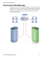
Deploying the BladeManager
The diagram below shows how the BladeManager may be set up to connect to
a management network and a public network. Equipped with its own Ethernet
switches, the two networks are physically separated. Any BladeManager user
who needs to access a blade server or switch must authenticate and pass
through the BladeManager.
AlterPath BladeManager Manual
1-7
1: Introduction
1-8
AlterPath BladeManager Manual
Chapter 2
BladeManager Installation
This section discusses the procedures and requirements for installing the
AlterPath BladeManager, and is organized as follows:
•
•
•
•
•
•
•
•
•
•
•
•
Product Installation Checklist
Rack Mounting Guidelines
Major Components of the BladeManager
Installing a DIMM
Installing a Hard Disk Drive
Installing a Simple-Swap Serial ATA Hard Disk Drive
Installing a SCSI Hard Disk Drive
Installing an Adapter
Completing an Installation
Connecting the Cables
Updating the Server Configuration
Preparing Console for Initial Configuration
Product Installation Checklist
Your AlterPath BladeManager is shipped with the following hardware
components:
•
•
•
•
•
BladeManager
Console cable (null modem)
Power cable
2 Ethernet cables
Mounting kit
2: BladeManager Installation
Rack Mounting Guidelines
When rack-mounting the BladeManager, consider the following:
•
•
•
•
•
•
•
•
•
•
•
•
•
•
2-2
Ensure the room temperature is below 35o C (95o F).
If you install the BladeManager in a closed or multi-rack assembly, the
operating ambient temperature of the rack environment may be greater
than the room ambient temperature. Ensure that you install the equipment
in an environment compatible with the manufacturer’s maximum rated
ambient temperature.
Do not block any air vents. Usually, 15 cm (6 in.) of air space provides
proper airflow.
Plan the device installation starting from the bottom of the rack cabinet.
Install the heaviest device in the bottom of the rack cabinet.
Do not extend more than one device out of the rack cabinet at the same
time.
Connect all power cords to properly wired and grounded electrical
outlets.
Maintain reliable earthing of rack mounted equipment by inspecting
supply connections other than direct connections to the branch circuit
such as power strips or extension cords.
Do not overload the power outlet when installing multiple devices in the
rack.
Remove the rack doors and side panels to provide easier access during
installation.
The slide rails in the kit come preset to the correct length for installing in
an IBM rack cabinet and they are adjustable for other rack cabinets.
The slide rails are marked RIGHT/FRONT and LEFT/FRONT for proper
placement on the rack-cabinet flanges.
Ensure that the equipment is mounted or loaded evenly to prevent a
potentially hazardous condition.
Do not place any object weighing more than 50 kg (110 lb) on top of rackmounting devices.
AlterPath BladeManager Manual
Rack Mounting Guidelines
To install the BladeManager in a rack cabinet, you need the following items:
•
•
•
2 slide rails
6 cable straps
6 M6 screws (for shipping and for securing vibration-prone areas)
a. Press on the rail-adjustment bracket (1) on the rear of the slide rail to
prevent the bracket from moving.
b. Press on tab (2) and tab (3) and slide the rail-locking carrier toward
the front of the slide rail until it snaps into place.
c. Press on tab (2) and tab (3) on the front rail-locking carrier and slide
the rail-locking carrier toward the rear of the slide until it snaps into
place.
AlterPath BladeManager Manual
2-3
2: BladeManager Installation
a. Lift the release tab (1) and fully extend the rail-adjustment bracket
from the rear of the slide rail until it snaps into place, if you need to
adjust the slide rail length.
b. Align the pins on the rear rail-locking carrier with the holes on the
rear mounting flange.
c. Press the tab (2) to secure the rear of the slide rail to the rear
mounting flange.
Important: Ensure that the pins are fully extended through the mounting
flange and slide rail.
2-4
AlterPath BladeManager Manual
Rack Mounting Guidelines
a. Align the pins (1) on the front rail-locking carrier to the front
mounting flange.
b. If you adjusted the rail length, push the rail-locking carrier back
toward the rear of the slide rail to align the slide rail with the
mounting flange.
c. Press the tab (2) to secure the front of the slide rail to the front
mounting flange.
d. Repeat steps 1 and 2 for the other slide rail.
AlterPath BladeManager Manual
2-5
2: BladeManager Installation
a. If you plan to transport the rack cabinet to another location with the
server installed, remove one screw and loosen the other screws as
indicated.
b. Fully extend the rail and re-insert the screw and tighten all screws to
secure the rail.
c. If you do not plan to transport the rack cabinet with to another
location with the server installed, continue with step 5.
2-6
AlterPath BladeManager Manual
Rack Mounting Guidelines
a. Align the server on the slide rails and push the server fully into the
rack cabinet. Secure the server to the front mounting flanges with the
captive thumbscrews (1).
Note: You must leave the shipping brackets (2) attached to the slide rails
unless the shipping brackets impede the server from sliding fully in the
rack cabinet. If you need to remove the shipping brackets, continue
with the next step.
AlterPath BladeManager Manual
2-7
2: BladeManager Installation
a. Press on the release tab (1) as indicated on the shipping bracket, and
remove the shipping from the slide rail.
b. Repeat previous step for the other shipping bracket.
c. Store the shipping bracket for future use.
Note: You just re-install the shipping brackets on the slide rails before you
transport the rack cabinet with the server installed. To re-install the
shipping brackets, reverse this step.
2-8
AlterPath BladeManager Manual
Rack Mounting Guidelines
a. Attach cables to the rear of the BladeManager (such as keyboard,
mouse, monitor cables, as needed).
b. Route the cables to the left corner of the BladeManager (as viewed
from the rear) and use the cable straps to secure the cables to the slide
rails.
AlterPath BladeManager Manual
2-9
2: BladeManager Installation
a. Before you transport the rack cabinet to another location with the
BladeManager installed, you must secure the server to the rack. If
necessary, disconnect the cables from the rear of the server; then,
slide the server out of the rack 150 mm (6 in.) and insert the M6
screws in each slide rail.
b. Secure the server or the rack cabinet with the M6 screws.
c. Ensure the rails are fully extended to the rear of the rack cabinet and
that the shipping brackets are installed.
d. Go to steps 4, 5, and 6 for instructions.
2-10
AlterPath BladeManager Manual
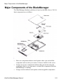
Major Components of the BladeManager
Major Components of the BladeManager
The BladeManager hardware platform is based on the IBM eServer 306. It’s
basic components are as follows:
•
•
•
Blue on a component indicates touch points where you can hold the
component such as when you remove it from or install it in the server.
Orange on or near a component indicates that you can hot-swap the
component (that is, you can remove or install the component while the
BladeManager is running).
Orange can also indicate touch points on hot-swappable components.
AlterPath BladeManager Manual
2-11
2: BladeManager Installation
Installation Safety Guidelines
System Reliability Guidelines
To help ensure proper cooling and system reliability, make sure that:
•
•
•
•
•
•
•
Each of the drive bays has a drive tray installed in it.
If the server has redundant power, each of the power-supply bays has a
power supply installed in it.
Allow the server cooling system to work properly by leaving
approximately 50mm (2.0 in.) of open space around the front and rear of
the server.
There are no objects in front of the fans.
You follow cabling instructions that come with optional adapters.
You replace a failed fan within 48 hours.
You do not remove the air baffle while the server is running since
operating the server without the air baffle might overheat the
microprocessor.
Static-Sensitive Devices
•
•
•
•
•
•
•
2-12
Static electricity can damage electronic devices, including your server. To
avoid damage, keep static-sensitive devices in their packages until you
are ready to install them.
Limit your movements as they build up static electricity around you.
Handle the device carefully, holding it by its edges or frame.
Do not touch solder joints, pins, or exposed circuitry.
Do not leave the device where others can handle and damage it.
While the device is still in its static-protective package, touch it to an
unpainted metal part of the server for at least two seconds to drain static
electricity from the package and from your body.
Remove the device from its package and install it directly into the server
without setting down the device. If you need to set down the device, place
AlterPath BladeManager Manual
Installation Procedures
•
it back into its package; do not place the device on your server or on a
metal surface.
Take extra care when handling devices during cold weather as heating
reduces indoor humidity and increases static electricity.
Installation Procedures
This section provides the following procedures:
•
•
•
•
•
Installing DIMMs
Installing a Simple-Swap Serial ATA Hard Disk Drive
Installing a SCSI Hard Drive
Installing an Adapter
Completing the Installation
Installing DIMMs
When installing dual inline memory modules (DIMMs), consider the
following information and guidelines:
•
•
•
•
•
Your server supports 256 MB, 512 MB, and 1 GB DIMMs, for a
maximum of 4 GB of system memory.
Depending on the server configuration, the installation will reduce the
amount of usable memory. A certain amount of memory must be reserved
for system resources. The BIOS displays the total amount of installed
memory and the amount of configured memory.
Your server comes with one 512 MB DIMM installed in DIMM
connector 1. If your system has one DIMM installed, when you install an
additional DIMM, you must install it in DIMM connector 3, and it must
be the same size, speed, type, and technology as the DIMM installed in
DIMM connector 1. You can mix compatible DIMMs from various
manufacturers.
If you install a second pair of DIMMs in DIMM connectors 2 and 4, they
do not have to be the same size, speed, type and technology as the
DIMMs installed in DIMM connectors 1 and 3. However, the size, speed,
type and technology of the DIMMs you install in connectors 2 and 4 must
match each other.
Install only 2.5 V, 184-pin, double-data-rate (DDR), PC2700 or PC3200,
unbuffered synchronous dynamic random-access memory (SDRAM)
AlterPath BladeManager Manual
2-13
2: BladeManager Installation
•
with error correcting code (ECC) DIMMs. These DIMMs must be
compatible with the latest PC2700 and PC3200 SDRAM unbuffered
DIMM specification.
When you restart your server, the system displays a message indicating
that the memory configuration has changed.
To install a DIMM, complete the following procedure:
1. Review the preceding installation guidelines.
2. Switch off the server and peripheral devices, and disconnect the power
cord and all external cables.
3. Remove the Cover.
Caution: To avoid breaking the retaining clips or damaging the DIMM
connectors, open and lose the clips gently.
4. Open the retaining clip on each side of the DIMM connector.
5. Touch the static-protective package containing the DIMM to any
unpainted metal surface on the server. Then, remove the DIMM from the
package.
2-14
AlterPath BladeManager Manual
Installation Procedures
6. Turn the DIMM so that the keys align with the slot.
7. Insert the DIMM into the connector by aligning the DIMM edges with the
slots at each end of the DIMM connector. Firmly press the DIMM straight
down into the connector by applying pressure on both ends of the DIMM
simultaneously. The retaining clips snap into the locked position when the
DIMM is firmly seated in the connector. If there is a gap between the
DIMM and the retaining clips, the DIMM has not been inserted correctly;
open the retaining clips, remove and reinsert the DIMM.
8. If you have other options to install, do so now.
9. Replace the cover.
10. Go to Completing the Installation, this chapter.
Installing a Hard Disk Drive
Follow the documentation that comes with the hard disk drive in addition to
the instructions in this chapter.
Installing a Simple-Swap Serial ATA Hard Disk
Drive
To install a simple-swap Serial ATA hard disk drive, complete the following
procedure:
Note: If you have only one hard disk drive, install it in the left drive bay.
1. Review the installation safety guidelines ar the beginning of this chapter.
2. Switch off the server and peripheral devices, and disconnect the power
cord and all external cables.
3. Press the release tabs on the bezel and pull the bezel away from the
server.
4. Slide the drive into the server until it connects to the backplane.
5. If you have other options to install, do so now.
6. Reinstall the bezel.
7. Go to Completing the Installation, this chapter.
AlterPath BladeManager Manual
2-15
2: BladeManager Installation
Installing a SCSI Hard Drive
To install a SCSI hard drive, complete the following procedure:
NOTE: If you have only one hard disk drive, install it in the left drive bay.
1. Review the safety installation guidelines at the beginning of this chapter.
2. Switch off the server and peripheral devices; disconnect the power cord
and all external cables.
3. Remove the cover.
4. Press the release tabs on the bezel and pull the bezel away from the server.
5. Slide the drive tray out of the server, and then position the drive on the
drive tray.
6. Secure the drive using the screws that come with the option.
7. Slide the drive tray back into the server.
8. Connect the signal and power cables to the drive
2-16
AlterPath BladeManager Manual
Installation Procedures
9. If you have other options to install, do so now.
10. Re-install the bezel and replace the cover. Go to Completing the
Installation, this chapter.
Installing an Adapter
This section describes the types of adapters that your server supports and
other information to consider when installing as adapter.
•
•
•
•
•
In addition to the instructions in this section, follow the instructions that
come with the adapter.
Your server comes with two peripheral component interconnect-extended
(PCI-X) adapter slots located on the riser card assembly. You must first
remove the riser card assembly to access the PCI-X connectors.
There are two 64-bit 66 MHz PCI-X slots.
You can install one low profile half-length adapter in expansion slot 1 and
one full-height, three-quarter length adapter in expansion slot 2.
The BladeManager supports 3.3 V or universal adapters.
AlterPath BladeManager Manual
2-17
2: BladeManager Installation
•
•
The BladeManager uses a rotational interrupt technique to configure PCIX adapters so that you can install PCI-X adapters that do not support
sharing of PCI-X interrupts.
The BladeManager scans PCI-X slots to assign system resources. If you
have not changed the default startup sequence, the BladeManager starts
devices in the following order:
a. CR-ROM and diskette drives
b. PCI-X slot 2
c. PCI-X clot 1
d. Integrated Ethernet controllers
•
•
•
•
•
2-18
The optional Remote Supervisor Adapter II can be installed only in PCIX slot 2.
You can install an optional RAID controller in your server to control the
internal hard disk drives (for example, to allow you to configure the
internal hard disk drives into disk arrays.
The optional ServeRAID-7t S-ATA controller can be installed only in
PCI-X slot 1. The low-profile bracket that comes with the controller is
required to install the controller.
The optional ServeRAID-6i+ controller can be installed only in PCI-X
slot 1. The low-profile bracket that comes with the controller is required
to install the controller.
No re-routing of the internal SCSI cable (SCSI models only) is required if
you are installing the ServeRAID-6i+ controller. The ServeRAID-6+
controller uses the SCSI connector (SCSI models only) for output.
AlterPath BladeManager Manual
Installation Procedures
To install an adapter, complete the following procedure:
1. Review the safety installation guidelines at the beginning of this chapter.
2. Switch off the server and peripheral devices; disconnect the power cord
and all external cables.
3. Remove the cover.
4. Follow the cabling instructions that come with the adapter. Route the
adapter cables before you install the adapter.
5. Follow the instructions that come with the adapter to set jumpers or
switches, if any.
6. Loosen the captive screw on the rear of the server and remove the risercard assembly. Place the riser-card assembly on a flat, static-protective
surfaced.
AlterPath BladeManager Manual
2-19
2: BladeManager Installation
7. Remove the expansion-slot cover.
Important: PCI expansion-slot covers must be installed on all vacant slots.
This maintains the electronic emissions characteristics of the
server and ensures proper cooling of server components.
8. Touch the static-protective package containing the adapter to any
unpainted metal surface on the BladeManager. Then, remove the adapter
from the static-protective package. Avoid touching the components and
gold-edge connectors on the adapter.
9. Place the adapter, component side up, on a flat, static-protective surface
and set any jumpers or switches as described by the adapter manufacturer,
if necessary.
Important: When you install an adapter in the riser-card assembly, carefully
grasp the adapter by its top edge or upper corners, and align it
with the PCI-X expansion slot; then, press the adapter firmly
into the expansion slot.
10. Re-install the riser-card assembly. Ensure that the riser-card assembly is
fully seated in the riser-card connector.
2-20
AlterPath BladeManager Manual
Installation Procedures
11. Tighten the captive screw on the rear of the server.
12. If you have other options to install, do so now.
13. Replace the cover. Go to Completing the Installation, this chapter.
Completing the Installation
To complete the installation, follow the steps below:
1. Re-install the cover.
2. Install the server in the rack cabinet.
Attention:
Install your server only in a rack cabinet with perforated doors.
Do not leave open space above or below an installed server in your rack
cabinet. To help prevent damage to server components, always install a
filler panel to cover the open space and to help ensure proper air
circulation. See the documentation that comes with your rack cabinet for
more information.
3. Connect the cables and power cords. See Connecting the Cables, this
section.
4. Update the server configuration. See Updating the Server Configuration,
this section.
AlterPath BladeManager Manual
2-21
2: BladeManager Installation
Connecting the Cables
The diagrams below show the locations of the input and output connectors on
the front and rear of the BladeManager.
1. Switch off the server before connecting (or disconnecting) cables from
your server.
2. See the documentation that comes with your external devices for
additional cabling instructions. It might be easier for you to route cables
before you connect devices to the BladeManager.
3. Cable identifiers are printed on the cables that come with the
BladeManager. Use these identifiers to connect the cables to the correct
connectors.
4. There is one keyboard connector on the back of the server. Use this
connector to connect the server to a keyboard or optional console switch.
You can also connect a USB keyboard to the server using one of the USB
ports. After installing a USB keyboard, you might need to use the
Configuration/Setup Utility program to enable keyboardless operation
and prevent the POST error message 301 from displaying during startup.
For more information about this option and how to connect it to the
BladeManager, see the documentation that comes with the option.
2-22
AlterPath BladeManager Manual
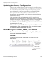
Updating the Server Configuration
Updating the Server Configuration
When you start the BladeManager for the first time after you add or remove
an internal option or external SCSI device, you might receive a message that
the configuration has changed. The Configuration/Setup Utility program
starts automatically so that you can save the new configuration settings.
Some options have device drivers that you need to install. See the
documentation that comes with the device information about installing any
required device drivers.
If the server has a RAID configuration using the SCSI controller with
integrated RAID (SCSI models only) or the integrated Serial ATA controller
with RAID and you have installed or removed a hard drive, you might have to
reconfigure your disk arrays. See the RAID documentation on the IBM
ServeRAID-7e (Adaptec HostRAID) Support CD for more information about
reconfiguring the disk arrays.
If the server has an optional RAID adapter and you have installed or removed
a hard disk drive, see the documentation that comes with the RAID adapter
for information about reconfiguring the disk arrays.
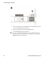
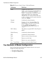
BladeManager Controls, LEDs, and Power
This section describes the controls and light-emitting diodes (LEDs) and how
to switch the BladeManager on and off.
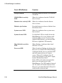
Front View
The diagram below shows the controls and LEDs on the front of the
BladeManager.
AlterPath BladeManager Manual
2-23
2: BladeManager Installation
2-24
Front LEDs/Buttons
Function
CD-eject button
Press this button to release a CD from the
CD-ROM.
CD-ROM drive activity
LED
When lit, it indicates that the CD-ROM
drive is in use.
Diskette drive activity LED
When lit, it indicates that the diskette
drive is in use.
Diskette-eject button
Press this button to release a diskette from
the diskette drive.
System-error LED
When lit, it indicates that a system error
has occurred.
System-locator LED
Use this blue LED to visually locate the
BladeManager if it is in a location with
numerous other servers. If your server
supports IBM director, you can use IBM
Director to light this LED remotely.
Hard disk drive activity
LED
When flashing, it indicates that a hard
disk drive is in use.
Power-on LED
When lit and not flashing, it indicates that
the server is switched ON. When flashing,
it indicates that the server is switched OFF
and still connected to an AC power
source. When off, it indicates that AC
power is not present, or the power supply
or the LED itself has failed.
If this LED is off, it does not mean that
there is no electrical power in the
BladeManager. The LED might be burned
out. To remove all electrical power from
the server, you must disconnect the power
cord from the electrical unit.
AlterPath BladeManager Manual
BladeManager Controls, LEDs, and Power
Front LEDs/Buttons
Function
Power-control button
Press this button to switch the server ON
and OFF manually.
Reset button
Press this button to reset the server and
run the power on self-test (POST). You
might have to use a pen or the end of a
straightened paper clip to press the button.
Rear View
The diagram below shows the LEDs on the rear of the BladeManager.
Rear LEDs
Function
Ethernet 1 transmit/receive
activity LED
This LED is on the Ethernet connector.
When lit, it indicates that there is activity
between the BladeManager and the
network.
Ethernet 1 speed 1 Gbps LED
This LED is on the Ethernet connector.
When lit, it indicates that the Ethernet
network speed is 1 Gbps. When off, it
indicates that the Ethernet network speed
is 10 Mbps or 1000 Mbps.
AlterPath BladeManager Manual
2-25
2: BladeManager Installation
Rear LEDs
Function
Ethernet 2 speed 1 Gbps LED
This LED is on the Ethernet connector.
When lit, it indicates that the Ethernet
network speed is 1 Gbps. When off, it
indicates that the Ethernet network speed
is 10 Mbps or 100 Mbps.
Ethernet 2 transmit/receive
activity LED
This LED is on the Ethernet connector.
When lit, it indicates that there is activity
between the BladeManager and the
network.
BladeManager Power Features
When the BladeManager is connected to an AC power source but is not
switched on, the operating system does not run, and all core login except for
the service processor is shut down. However, the server can respond to
requests from the service processor, such as a remote request to turn on the
server. The power-on LED flashes to indicate that the server is connected to
AC power but not switched on.
Switching On the Server
Approximately 20 seconds after the BladeManager is connected to AC power,
the power-control button becomes active, and you can switch on the
BladeManager and start the operating system by pressing the power-control
button.
You can also switch on the BladeManager in any of the following ways:
•
•
•
2-26
If a power failure occurs while the BladeManager is switched on, the
BladeManager will start automatically when power is restored.
If the BladeManager is connected to an Advanced System Management
interconnect network that contains at least one server with an optional
Remote Supervisor Adapter II installed, the BladeManager can be
switched on form the Remote Supervisor Adapter II user interface.
If your operating system supports the system-management software for an
optional Remote Supervisor Adapter II, the system-management software
can switch on the BladeManager.
AlterPath BladeManager Manual
BladeManager Power Features
•
If your operating system supports the Wake on LAN feature, the Wake on
LAN feature can switch on the BladeManager.
Note: When 4 GB or more memory (physical or logical) is installed, some
memory is reserved for various system resources and is unavailable to
the operating system. The amount of memory that is reserved for
system resources depends on the operating system, the BladeManager
configuration, and the configured PCI options.
Switching Off the BladeManager
When you switch off the BladeManager and leave it connected to AC power,
the BladeManager can respond to requests from the Service processor, such
as a remote request to turn on the server. To remove all power from the server,
you must disconnect it form the power source.
Caution: The power control button on the device and the power switch on
the power supply do not turn off the electrical current supplied to
the device. The device also might have more than one power cord.
To remove all electrical current from the device, ensure that all
power cords are disconnected from the power source.
You can switch off the BladeManager in any of the following ways:
•
•
•
•
•
You can switch off the BladeManager from the operating system if your
operating system supports this feature. After an orderly shutdown of the
operating system, BladeManager will switch off automatically.
You can press the power-control button to start an orderly shutdown of
the operating system and switch off the BladeManager if your operating
system supports this feature.
If the operating system stops functioning, you can press and hold the
power-control button for more than 4 seconds to switch off the
BladeManager.
If the BladeManager is connected to an Advanced System Management
interconnect network that contains at least one server with an optional
Remote Supervisor Adapter II installed, the BladeManager can be
switched off from the Remote Supervisor Adapter II user interface.
If an optional Remote Supervisor Adapter II is installed in the server, the
server can be switched off from the Remote Supervisor Adapter II user
interface.
AlterPath BladeManager Manual
2-27
2: BladeManager Installation
•
•
If the Wake on LAN feature switched on the BladeManager, the Wake on
LAN can switch off the BladeManager.
You can switch off the BladeManager through a request from the service
processor.
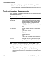
Pre-Configuration Requirements
Before configuring BladeManager, ensure that you have the following system
set up and information ready:
Requirement
Description
HyperTerminal, Kermit,
or Minicom
If you are using a PC, ensure that
HyperTerminal is installed on your Windows
operating system. If you are using the UNIX
operating system, use Kermit or Minicom.
NOTE: You will need Root Access on your
local UNIX machine in order to use the serial
port.
IP Addresses
Have the IP/Mask addresses of the following
ready:
- All Console Servers
- Gateway
- DNS
Optional addresses:
- NTP
- SMTP (only when using the alarms feature).
NIC Card
Ensure that you have a NIC card installed in
your PC to provide an Ethernet port, and
allow network access.
Note: To complete the configuration process, SKIP to Chapter 4: Web
Administration and refer to the “First Time Configuration Wizard” on
page 4-4.
Note: Chapter 3: BladeManager Web Access is designed for regular users
who will use or operate the application after the BladeManager
administrator has completed the configuration procedures discussed in
chapter 4.
2-28
AlterPath BladeManager Manual
Configuring the COM Port Connection and Logging In
Note: For a list of internet browsers and Cyclades device firmware versions
supported by the BladeManager, refer to Appendix A: Hardware
Specifications.
Configuring the COM Port Connection and
Logging In
The console port is used for the initial configuration (also known as First
Time Configuration in this document) which is performed using the
Command Line Interface (CLI) via serial console connection.
First Time Configuration is responsible for establishing the superusers for the
CLI (hardware configuration) and the BladeManager web interface and
configuring the BladeManager connectivity and system settings. The process
is discussed in more detail in Chapter 4: Configuring the BladeManager.
Before using the terminal, make sure it is configured as follows:
1. Select available COM port.
In Hyper Terminal (Start > Program > Accessories), select File >
Properties, and click the Connect To tab. Select the available COM port
number from the Connection dropdown.
2. Configure COM port.
Click the Configure button.
Your PC, considered here to be a “dumb terminal,” should be configured
as follows:
•
•
•
•
•
•
Serial Speed: 9600 bps
Data Length: 8 bits
Parity: None
Stop Bits: 1 stop bit
Flow Control: none
ANSI emulation
3. Power on the BladeManager
4. Click OK on the Properties window.
You will see the BladeManager booting on your screen. After it finishes
booting, you should see the configuration screen.
AlterPath BladeManager Manual
2-29
2: BladeManager Installation
2-30
AlterPath BladeManager Manual
Chapter 3
BladeManager Web Access
The web interface provides two modes for using the BladeManager based on
the type of user: Access (for operation by regular users) and Admin (for
configuration by system administrators). This chapter explains the procedures
for operating the BladeManager web interface in Access Mode.
Addressed specifically to regular users, this chapter is organized as follows:
•
•
•
•
•
•
•
User Interface Overview
Accessing the BladeManager Web Management Interface
Logging In
Using the Alarms forms
Using the Blades forms
Using the Logs forms
Using the User Profile forms
If you are a BladeManager administrator, refer to Chapter 4: BladeManager
Web Administration.
User Interface Overview
The BladeManager user interface (in Access Mode) has four main menu
options:
Menu Option
Function
Alarms
The Alarms list form is the first form that you
see (or the default form) when you log in. Use
this form to view alarms, update the status of
an alarm or close an alarm after resolving it.
3: BladeManager Web Access
Menu Option
Function
Blades
Use the Blades form to view a list of blades
assigned to you. From the list, select the blade
you wish to access, or select the blade from the
drop down menu on the top left, and then click
on Connect.
The blades list form provides access to the
chassis blades and switches.
Logs
Use the Logs form to view the Access Logs,
Events Logs, and Data Buffer for a particular
blade or chassis. You can also access logs from
the Blade List form.
User’s Profile
The User’s Profile form displays the profile of
only the user currently logged in. Use the User
Profile to view or modify your own user
information, as well as your own security
profile.
Using the Web Interface as a Regular User
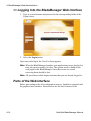
To open the BladeManager web application, perform the following steps:
1. Type in the following URL from your web browser:
https://nnn.nnn.nnn.nnn
Where: nnn.nnn.nnn.nnn is the IP address provided to you by your
BladeManager administrator.
The IP address works for both encrypted (https) and non-encrypted (http)
versions. Cyclades recommends that you use the encrypted version.
Note: To configure the encrypted version, see “Disabling HTTP to Use Only
HTTPS” on page 5-16, Chapter 5: Advanced Configuration.
3-2
AlterPath BladeManager Manual
User Interface Overview
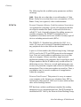
2. When the Login screen appears, enter your user name and password as
provided by your system administrator.
3. Select the Login button.
Upon successful login, the Alarms form appears.
Note: The first time BladeManager launches your application screens, the
process will be slow. Once the screens are cached, subsequent retrieval
of screens should be fast.
AlterPath BladeManager Manual
3-3
3: BladeManager Web Access
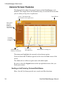
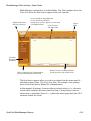
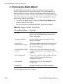
General Screen Features
The diagram below shows the general features of the BladeManager web
interface. The sample form is for illustration only; it is not the first screen that
you see when you log in as a regular user.
“Access” tab indicates that
user interface is for regular users.
Logout Button
Menu panel
showing
Blades as
the selected
menu choice.
Username
and primary
IP address
Online help and
firmware version info.
User view or
data input form
Buttons panel to manage list
The menu panel highlights the currently selected menu option.
Your user name and IP address appears on the lower left hand corner of the
screen.
The Admin tab is visible to regular users with admin rights.
Be sure to select the Logout button on the top right hand corner after you
finish your session.
Sorting a List Form by Column/Field Name
Most, if not all, list forms provide sort, search, and filter functions.
3-4
AlterPath BladeManager Manual
Alarms
An underlined column name indicates that the list can be sorted by the
column name. The Blade List form, for example, allows you to sort by Blade,
Type, Device, Location, or Status. To sort by Location, simply click the
column name, Location.
The arrow adjacent to the heading indicates that the list is sorted based on that
heading. The position of the arrowhead indicates the sort order. A downward
arrowhead indicates that the list is alphanumerically arranged in ascending
order; an upward arrowhead, in descending order. You can change the sort
order by clicking on the heading or the arrow.
Search and Filter Functions
When available, you will find the Search and Filter by buttons at the bottom
of the List form.
This allows you to search through a List form by selecting the search category
(i.e., Blade group) from the dropdown field and selecting the Search button.
You can also filter your search by selecting a category from the Filter by
dropdown field and selecting the Filter by button. The system automatically
saves the filtered list.
Alarms
The Alarm List form is the default form of the BladeManager Web Interface
in Access mode. An alarm is a brief message alerting you of a possible
problem that requires an action.
When BladeManager detects an alarm, it sends the alarm along with a ticket
number to the user’s Alarm List form. As a user, you should see only those
alarms assigned to you by your administrator.
If the trigger for the alarm has been configured to send an email, then you
should also receive an email notification regarding the alarm. Each alarm or
ticket in the list includes a timestamp, a priority level, and a status.
AlterPath BladeManager Manual
3-5
3: BladeManager Web Access
Alarm Logs
The BladeManager not only stores each alarm in a database, but also
maintains a log for each alarm. There are two ways in which you can view
alarm logs:
•
•
From the Alarms List form
From the Logs form (Logs > Data Buffer)
Responding to an alarm
Since no two issues are exactly the same, you have several ways to respond to
an alarm depending on its nature and severity. A “typical” procedure for
responding to an alarm is as follows:
•
•
Accept the ticket or assignment.
Reassign the ticket or assignment to another user, and optionally add
notes about the ticket.
Once assigned, the user working on the ticket can perform any of the
following procedures to resolve the alarm or complete the ticket:
•
•
•
•
•
•
View Blade Log and other related logs.
Edit information ticket by changing the status and adding notes.
Connect to the blade.
Run a console session.
If problem is fixed, change the alarm status and close the ticket.
Re-assign the ticket to another user.
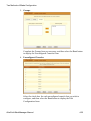
Alarm List Form
When you first log in to the BladeManager as a regular user or select Alarms
from the menu, the Alarm List form is the first form that you will see. Use this
form to view the list of alarms, to connect to a blade, and to view blade logs.
3-6
AlterPath BladeManager Manual
Alarms
To re-assign the current ticket, change the ticket status, and add notes or
comments, use the Alarm Detail (or Ticket Info) form.
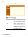
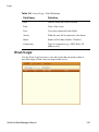
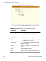
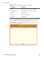
Table 3-1: Form Fields and Elements
Fieldname
Definition
Ticket
Ticket number assigned to an alarm. The
symbol above the ticket number indicates the
severity level of the alarm. Select the number
to display the Alarm Detail form.
Blade
Blade from which the alarm originated. Click
on the blade name to enable a console session
according to the type of configured device and
console. For example, a serial console will
establish a text-based session; a KVM console
will launch the KVM viewer, and an IPMI
console will launch the SSH applet and
connect to the IPMI SOL console.
AlterPath BladeManager Manual
3-7
3: BladeManager Web Access
Table 3-1: Form Fields and Elements
Fieldname
Definition
Blade Config
Blade configuration. Select this to view the
Blade Detail form (which includes the
secondary form: Console Notify, Console
Access, and Console Group) for the particular
console record.
Alarm Trigger
The Alarm Trigger name. Click on the name to
view the Alarm Trigger Detail form.
User Assigned
User assigned to the alarm.
Status
Status of the alarm.
Blade Log
Select this to navigate to the Data Buffer log
pertaining to the blade.
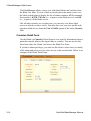
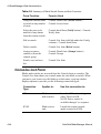
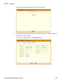
Viewing the Alarm Detail Form
The Alarm Detail form contains detailed information about the ticket as
generated by an alarm. It allows you to re-assign the ticket, update the status,
and enter notes regarding the alarm or ticket.
To view the ticket information for an alarm, follow the steps below:
1. From the Alarm List form, click on the ticket number.
3-8
AlterPath BladeManager Manual
Alarms
The form brings up the Alarm Detail form.
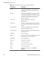
Table 3-2: Form Fields and Elements
Fieldname / Button
Definition
Assigned Users
Dropdown box that lists all the assigned users
for the current alarm. Select a user to assign or
re-assign ticket to another individual user.
Status
Dropdown box to select the status of the ticket.
Messages
The system-generated message(s) pertaining to
the alarm.
Notes
Text entry box for entering notes or comments
about the current ticket or alarm.
Back
Button to return to the Alarm List form.
Save
Button to save your entries.
Reset
Button to reset the form to its original or default
values.
AlterPath BladeManager Manual
3-9
3: BladeManager Web Access
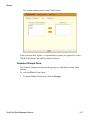
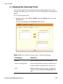
>> Viewing Alarm or Console Logs
You can view the console log for a particular alarm or ticket from the Alarm
List form. To view the console log, follow the step below:
1. From the Alarm List form, under the Console Log column heading, select
the corresponding view link for the console log you wish to view.
The system displays the Logs form:
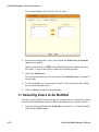
>> Assigning a Ticket to a User
To assign or re-assign a ticket to a user, follow these steps:
1. From the Alarm List form, select an alarm or ticket to open the Alarm
Detail or Ticket Information form.
The system opens the Alarm Detail form.
2. From the Ticket Information form, select user from the Assigned Users
dropdown list box.
3. If applicable, select the status from the Status dropdown list box.
4. If applicable, type in your notes or comments in the Notes text entry box.
5. Select Save to complete your entry.
3-10
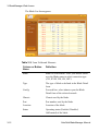
AlterPath BladeManager Manual
Blades
Blades
Selecting Blades from the menu brings up the Consoles List form which
allows you to:
•
•
•
•
View detailed information about the blade consoles and switches assigned
to you.
Open a command line console session for a selected blade or switch.
Launch the KVM Viewer and connect you to a KVM port (for KVM/net)
Power ON or OFF the selected blade or switch.
Access to blades and switches and the types of connection are configured by
the System Administrator from the Security Profile. You can view your
security profile by going to Users > Security.
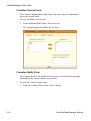
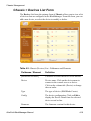
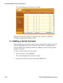
>> Viewing the Blade List
The Blades List form allows you to view the blades to which you have
authorized access.
To view the Blade List form, follow this step:
1. From the Blades form, under the Config column, select the view link
adjacent to the blade you wish to view.
AlterPath BladeManager Manual
3-11
3: BladeManager Web Access
The Blade List form appears.
Table 3-3: Form Fields and Elements
3-12
Column or Button
Name
Definition
Blade
Blade or switch name. Place your mouse cursor
over the Blade name to select connection type
(CLI, KVM, VM, ON, OFF).
Type
The type of blade as defined in the Blade Detail
form.
Config
For each line, select view to open the Blade
Detail form of the selected console.
Chassis
Chassis used by the blade.
Port
Port number used by the blade.
Location
Location of the blade.
Status
Operating status (Enabled, Disabled,
OnDemand) of the blade.
AlterPath BladeManager Manual
Blades
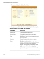
Table 3-3: Form Fields and Elements
Column or Button
Name
Definition
Save View
Button to save the desired blade list and sort
order.
Filter By
Button to filter your search by Blade Group
Name which you select from the dropdown box.
Search
Button to search by individual console name
which you select from the dropdown box.
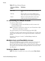
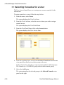
>> Connecting to a Blade Console
To connect to a blade console:
1. From the Blade List form, select the blade you wish to connect to by
selecting the blade name.
Note: If a modem is connected to a remote site, you will experience a slight
delay before connecting to a console.
The system connects you to a console through Secure Shell (SSH).
In KVM/net, the listed console names are the KVM/net ports. Clicking on the
console name will launch the ActiveX application and make a connection to
the port.
Regardless of the type of “console,” the BladeManager handles the
authentication.
Multiple Users and Read/Write Access
Because the BladeManager supports multiple connections to the same port,
this makes it possible for multiple users to view the same form. Note,
however, that only the first user to connect to that port can have full Read and
Write (R/W) access to the blade console panel while the rest can have Read
only (R) access.
Viewing a Blade or Switch
Note: This feature is available only to users of the optional Blade Module.
AlterPath BladeManager Manual
3-13
3: BladeManager Web Access
The BladeManager allows you to view individual blades and switches from
the Blade List form. To view a blade or switch, place the mouse cursor over
the blade/switch name to display the list of connect options: CLI (command
line interface), KVM, VM, On (i.e., to power on the blade server), and Off
(i.e., to power off the blade server).
Like all other consoles, as a regular user, you can only view those blade
servers to which you have access. You may also view your user profile with
regards to blade access from the User’s Profile option of the menu, Security
form.
Consoles Detail Form
Use the Blade (or Consoles) Detail form to view specific information about a
particular console (that is, the target blade or console). You can invoke this
form from either the Alarm List form or the Blade List form.
If you have admin privileges, you also use this form to select user(s) to notify
of the alarm and select user(s) to have access to the current blade. Below is an
example of the Blade Detail form.
3-14
AlterPath BladeManager Manual
Blades
Table 3-4: Form Fields and Elements
Field Name
Definition
Details
Button to display the Console Detail form.
Access
Button to view users who are authorized to
access the current console.
Notify
Button to view users who can be notified of an
alarm pertaining to the current console.
Groups
Button to view the group(s) to which the
current console belongs.
Console Name
Name of the (target) console.
Device Name
Name of the device used by the console.
Port
Name of port used by the console.
Status
Status of the target console (Able, Disable, On
Demand).
Description
A brief description of the console.
Location
Physical location of the blade console.
Machine Type
Type of target system.
Machine Name
Other applicable system name.
OS Type
Operating system used by the console.
OS Version
Version of operating system.
Back
Button to return to the previous page or form.
AlterPath BladeManager Manual
3-15
3: BladeManager Web Access
Consoles Access Form
The Consoles Access tabbed form shows the users who are authorized to
access the current blade.
To view the Blade Access form:
1. From the Blade Detail form, click on Access.
The system displays the Blade Access form:
Consoles Notify Form
The Console Notify form shows the users who are notified when an alarm
pertaining to the current console is generated.
To view the Console Notify form:
1. From the Console Detail form, click on Notify.
3-16
AlterPath BladeManager Manual
Blades
The system displays the Console Notify form:
In the selection box, a plus (+) sign indicates a group, as opposed to a user.
USER is the default list which contains all users.
Consoles Groups Form
The Console Groups form shows the group(s) to which the current blade
belongs.
To view the Blade Group form:
1. From the Blade Detail form, click on Groups.
AlterPath BladeManager Manual
3-17
3: BladeManager Web Access
The system displays the Blade Group form:
Logs
The Logs option of the menu allows you to select and view three types of logs
pertaining to the blade(s) assigned to you:
Log Type
Definition
Access Log
Logs that provide logging information (i.e.,
who accessed the blade, when and for how
long, etc.) about a particular blade.
Events Log
Logs that provide information about
notifications and alarms (who handled the
alarm, what action was taken, etc.) triggered
by a particular blade.
Data Buffer
This is a log of all transaction data generated
on the blade.
All three logs are available for the specified blade. To access each log, select
the appropriate log type from the title bar. As with blades and alarms, you can
only view the logs of systems to which you have authorized access.
3-18
AlterPath BladeManager Manual
Logs
When you select Logs from the menu panel, the primary form, shown below,
will prompt you for a range of dates from which to retrieve your logs.
Table 3-5: Form Fields and Elements
Field Name
Definition
Console
Drop down list to select a blade server that
will be the basis of the log(s) to be retrieved.
Date From
Drop down list to select the starting date of the
log(s) to be viewed.
Date To
Drop down list to select the end date of the
log(s) to be viewed.
Retrieve
Button to download the requested log(s) and
display the Log forms.
>> Viewing the Logs
To view the logs available for a specified blade (to which you have authorized
access), perform the following steps:
1. Select Logs from the menu.
AlterPath BladeManager Manual
3-19
3: BladeManager Web Access
The system brings up the main Blade Logs form.
2. From the Blade drop down list, select the blade from which you want to
view the logs.
Note: You can only view or access the logs of blades to which you have
authorized access.
3. Select a range of dates from which to base your logs by selecting from the
Date From and Date to drop down lists.
The system brings up the Logs Detail form.
Access Logs
Use Access Logs form to view the Access Logs, Event Logs, and Data Buffer
Logs. The Access Logs (default log browser) provide all access information
(e.g., who accessed the blade, access date, action taken, etc.) about your target
blade server.
The name of the blade/port/chassis to which the logs apply to is shown below
the tab titles.
3-20
AlterPath BladeManager Manual
Logs
Table 3-6: Access Logs - Field Definition
Field Name
Definition
Date
Date in which the event occurred.
Time
Time of the event.
User
User who connected to the blade.
Action
What the user did in response to the alarm.
Status
Status of the blade (Enable / Disable).
Connection
Type of connection (e.g., SSH, Web); IP
address used.
Event Logs
Use the Event Logs browser to view all events that occurred (within a
specified range of time) on your target blade server.
AlterPath BladeManager Manual
3-21
3: BladeManager Web Access
Table 3-7: Event Logs - Field Definition
Field Name
Definition
Date
Date of the event.
Time
Time of the event.
Ticket
Ticket number associated with the event.
Pattern
Trigger Expression
Action
Action taken to resolve event.
Data Buffer
Use the Data Buffer browser to view the contents of the data buffer generated
by a target blade server.
Note: You can also access the Data Buffer log from the Alarms form.
3-22
AlterPath BladeManager Manual
User’s Profile
User’s Profile
The User’s Profile form allows you to view your profile or contact
information and modify a limited number of fields. The system allows you to
view only your own profile.
The User’s Profile has four tabbed forms. See the Form Fields and Elements
table for the function of each form.
Table 3-8: Users Profile, Details Form - Fields and Elements
Field Name
Definition
Details
Tab or button to display the User Detail form.
This is also the primary form of User’s
Profile.
Access
Tab/button to display the User Access form
which shows all blades assigned to the current
user.
AlterPath BladeManager Manual
3-23
3: BladeManager Web Access
Table 3-8: Users Profile, Details Form - Fields and Elements
3-24
Field Name
Definition
Groups
Tab/button to display the User Group form
which shows all groups to which the current
user belongs.
Security
Tab/button to display the Security form which
shows the security profiles assigned to you. A
security profile defines a user’s access control
to a device, and to which user group that
profile is assigned.
User Name
The user name used to log into the
BladeManager.
Admin User
Check box to indicate that the user has Admin
privileges, and also belongs to the Admin user
group.
Security Profile
Check box to indicate that a security profile
has been assigned to the user.
Local Password
Check box to indicate that local authentication
applies to the user.
Full Name
User’s full name.
Email
User’s email. This is the same field name used
by the system for event notification.
Department
User’s department.
Location
Location of department.
Phone
User’s phone number.
Mobile
User’s mobile phone number.
Pager
User’s pager number.
Status
Indicates whether the user is enabled or
disabled.
AlterPath BladeManager Manual
User’s Profile
>> Changing Your Password
To change your password, perform the following steps:
1. From the User’s Profile detail form, click on Set Password.
2. From the password dialog box, enter the new password twice.
3. Click on Submit.
>> Viewing the User Access Form
The User Access form shows the blades that the current user can access.
To view the User Access form:
1. From the User Detail form, click on Access.
The system displays the User Access form:
>> Viewing the User Groups Form
The User Groups tabbed form displays the groups to which you belong.
To view the User Group form:
1. From the User Detail form, click on Groups.
AlterPath BladeManager Manual
3-25
3: BladeManager Web Access
The system displays the User Group form:
Table 3-9: User’s Profile, Groups Form - Fields and Elements
3-26
Field Name
Definition
Groups
Tab or button to select the current form.
Select groups for the user
List box from which to select a possible list of
user groups assignable to the current user.
Add
Button to add a selected user group (left list
box) to the Selected groups list box.
Delete
Button to delete a selected user group (right
list box) and return it to the Select groups for
the user list box.
Selected Groups
The list box that shows the group(s) assigned
to the current user.
AlterPath BladeManager Manual
User’s Profile
>> Viewing the Security Form
The Security form shows the current security profile assigned to you (for
example, the blades you are allowed to access), including any other applicable
profiles.
To view the Security form:
1. From the menu, select User’s Profile; from the Details form, select the
Security tab.
The system displays the Security tabbed form:
Table 3-10: User’s Profile, Security Form - Fields and Elements
Field Name
Definition
Security
Tab or button to select the current form.
Select security profile
List box from which to select a possible list of
security profiles assigned to the current user.
Add
Button to add a selected security profile (left
list box) to the Selected security profiles list
box.
AlterPath BladeManager Manual
3-27
3: BladeManager Web Access
Table 3-10: User’s Profile, Security Form - Fields and Elements
3-28
Field Name
Definition
Delete
Button to delete a selected security profile
(right list box) and return it to the Select
security profile list box.
Selected security profiles
The list box that shows the Security Profile
assigned to the current user.
Security profiles via user
groups
The list box that shows the Security Profile
assigned to a user group (that is, the default
USER group or any other defined user
groups).
AlterPath BladeManager Manual
Chapter 4
BladeManager Web
Administration
This chapter presents the procedures for configuring the AlterPath
BladeManager through the web interface. Addressed to the BladeManager
administrator who must use the web interface in the Admin Mode, the chapter
is organized as follows:
•
•
•
•
•
•
•
•
•
•
•
•
•
•
•
•
•
•
•
•
•
•
•
Operational Modes
Configuration Process Flow
First Time Configuration Wizard
BladeManager Web Interface: Admin Mode
Forms Summary
Parts of the Web Interface
Chassis Management
Proxies
Two Methods of Blade Configuration
Configuring Blades Manually through the Menu
Deleting a Device Group
Alarm Trigger Management
Blades / Switches
Log Rotation
Users
User List form
Setting the Local Password
Groups
Security Profiles
Backing Up User Data
System Recovery Guidelines
BladeManager Database Transaction Support
Info / Reporting
4: BladeManager Web Administration
Operational Modes
The BladeManager provides two operating modes for configuration:
• First Time Configuration (CLI or text-based)
• Admin Mode (GUI-based)
Before you can use the BladeManager web interface you must first run the
First Time Configuration wizard.
The admin user, by default, is the system administrator of the BladeManager
web interface and runs the application in Admin mode. This designation
cannot be revoked. Unless a regular user has been configured to be an admin
user as well (through the User Detail form), regular users can use the
application only in Access mode.
Only an administrator or admin user can use the web interface in Admin
Mode which allows them to perform configuration procedures such as
assigning admin roles to new users, adding new blades and alarms.
Note: For information on how to use the system in Access mode, refer to the
previous Chapter 3: BladeManager Web Access .
Note: Certain configurational procedures (e.g., System Recovery, Modem
Card Configuration) require the use of the CLI by advanced users.
These procedures are discussed in Chapter 5: Advanced
Configuration.
4-2
AlterPath BladeManager Manual
Configuration Process Flow
Configuration Process Flow
The entire configuration process through the web interface is as follows:
Connect to
serial console
Perform
First Time
Configuration
Reboot
successful?
N
Reset system
to default
factory settings
Y
Logon to
Blade Manager
as Admin
SEVEN MENU OPTIONS
Chassis
Blades /
Switches
Users
Chassis
Detail
Blade /
Switch
Detail
User
Detail
Group
Notify
Password
Access
Group
AlterPath BladeManager Manual
Access
Alarm
Trigger
Alarm
Detail
Groups
Security
Profiles
Info /
Reporting
Chassis
Group
Blade
Group
User
Group
Group
4-3
4: BladeManager Web Administration
You must perform the First Time Configuration process (see Configuration
Flow Diagram) using the command line interface. Once completed, you may
perform the rest of the configuration process and all daily administration
procedures through the BladeManager web interface.
First Time Configuration Wizard
The first time configuration process is designed to:
•
•
•
Establish user as root, the superuser for the CLI.
Establish user as Admin, the superuser for the BladeManager web
interface.
Initialize your system and user settings to ensure full connectivity and
functionality of the BladeManager.
First Time Configuration requires that you:
•
•
Connect to a serial console
Log in as root
Before you run First Time Configuration, check to ensure that your system is
set up properly. If you are using a PC, ensure that HyperTerminal is installed
on your Windows operating system. If you are using the UNIX operating
system, use Kermit or Minicom.
Ensure that you have a NIC card installed in your PC to provide an Ethernet
port, and allow network access.
Refer to Chapter 2: BladeManager Installation for procedures on how to
prepare for First Time Configuration.
>> Running the First Time Configuration Wizard
To initiate the First Time Configuration Wizard, follows the steps below:
1. Connect the management console to the BladeManager unit.
2. Boot your management console.
3. Follow the configuration wizard. You may configure the following
manually, or press Return to accept the default value(s).
•
•
•
4-4
Enter Root password (and re-type)
Enter Admin password (and re-type)
Select Time Zone
AlterPath BladeManager Manual
First Time Configuration Wizard
•
•
•
•
•
•
•
•
•
•
•
•
Enter Date (format MM/DD/YYYY)
Enter Primary Ethernet IP Address (Static/None).
Enter Secondary Ethernet IP Address (Static/None)
Configure Ethernet Subinterfaces (Yes/No/List)
Configure Ethernet VLANs (Yes/No/List)
Enter Ethernet default gateway
Enter System’s Hostname (30 characters max)
Enter System’s Domain name (60 characters max)
Enter Primary nameserver’s IP address
Enter the NTP Server
Enter email (SMTP) server
Enter Authentication Method (local/radius/tacacs+/ldap/kerberos/nis/
active_directory)
Note: Depending on the Authentication Method that you select, the system
will prompt you for additional information. See “Setting the
Authentication Method” on page 4-8 for more information.
>> Resetting Configuration to Factory Settings
If you make a mistake during the First Time Configuration (or if you need to
make a change in the configuration), you can reset the configuration to its
factory default settings and start over. To reset the configuration, follow these
steps:
1. Log in to the management console as root.
2. Type in: defconf and press <Enter>.
3. Type in: reboot and press <Enter>.
Example:
BladeManager login: root
Password:
.
.
[root@BladeManager root]# defconf
WARNING: this will erase all of your current configuration and restore the
system's factory default configuration. This action is irreversible!
AlterPath BladeManager Manual
4-5
4: BladeManager Web Administration
Are you sure you wish to continue? (Y/N) y
Restoring default configuration ... done.
The new configuration will take effect after the next boot.
[root@BladeManager root]# reboot
Refer to the sample First Time Configuration, next section, to view how
the parameters are entered into the system.
4. Save and reboot.
Once saved, the BladeManager applies the new configuration to the
system and saves the information on a Compact Flash card.
First Time Configuration Wizard: An Example
The First Time Configuration sample session shown below shows the portion
of the command line data where the user configuration begins. This is
commenced by the heading, Welcome to Cyclades-APBM!
Caution: Before the Welcome heading appears, the system will prompt you
for the following:
Do you
Do you
Do you
Do you
[n]
want
want
want
want
to
to
to
to
re-create
re-create
re-create
re-create
hard disk partitions? (y/n) [n]
the System file system?(y/n)[n]
the Console Log file system?(y/n)[n]
the Configuration file system?(y/n)
Be sure to answer no to the above questions. Once completed, you should see
the configuration text as shown in the example below.
Note: Default values are enclosed in angled brackets after each question or
prompt. Press <Enter> to accept the default value.
=====================================================
Welcome to Cyclades-APBM!
Since this is the first time you are booting your APBM, you need to
answer some basic configuration questions. Once this is done, the
other APBM configuration parameters can be set through its Web
Management Interface (WMI).
Press any key to continue.
4-6
AlterPath BladeManager Manual
First Time Configuration Wizard
You must now set a password for 'root', the system administrative
account.
WARNING: this is a very powerful account, and as such it's advisable
that its password is chosen with care and kept within the reach of
system administrators only.
New password:
Re-enter new password:
Password changed
You must now set a password for 'admin', the administrative account for
the Web Management Interface (WMI).
WARNING: this is a very powerful account, and as such it's advisable
that its password is chosen with care and kept within the reach of
system administrators only.
New password:
Re-enter new password:
Password changed
Please choose the time zone where this machine is located.
Current system date and time is:
Tue Apr 5 17:11:18 PDT 2005
Press ENTER to accept it or specify new ones.
Enter date in MM/DD/YYYY format: 48
Enter date in MM/DD/YYYY format:
Tue Apr 5 17:11:00 PDT 2005
Primary Ethernet IP address: (S)tatic or (N)one ? [S]:
Secondary Ethernet IP address: (S)tatic or (N)one ? [S]:
Configure Ethernet Subinterfaces: (Y)es, (N)o or (L)ist ? [N]: n
Configure Ethernet VLANs: (Y)es, (N)o or (L)ist ? [N]: n
Enter Ethernet Default Gateway [none]:
Enter the System's Hostname
(max 30 characters) [E2000]:
Enter the System's Domain Name
(max 60 chars) [localdomain]:
Enter the Primary Nameserver's IP address [none]:
Enter the NTP server:
Enter the email (SMTP) server:
Choose the desirable authentication method
(local/radius/tacacs+/ldap/kerberos/nis/active_directory) [local]:
Cyclades-APBM V_1.3.0 (Apr/03/2005) - Console (kernel 2.4.25)
APBM login:
[At this point, First Time Configuration is complete. Close the terminal
session and proceed to the web interface.]
=====================================================
AlterPath BladeManager Manual
4-7
4: BladeManager Web Administration
Setting the Authentication Method
The sample First Time Configuration shows local as the Authentication
Method to use to authenticate a user.
Depending on the type of authentication service that you select, the wizard
will prompt for questions relating to the authentication service of your choice.
For example, if you select RADIUS, the system will prompt you for the
RADIUS server name and the secret. Selecting TACACS+ will prompt you
for the TACACS+ server IP address, the shared secret, and the available
service (system).
If you select NIS, the system will prompt you for the NIS Domain Name and
the NIS Server. For the NIS Domain Name, the system will accept
localdomain or you may leave the field blank.
Note: If you use NIS Authentication and the NIS server fails, APBM will not
allow you to add the user in the local database since it already exists in
the NIS server. This is due to the way NIS centralizes and distributes
user account information into common local files. For more detailed
information, see “NIS Configuration” on page 5-8 of Chapter 5:
Advanced Configuration.
Configuring Active Directory
To use Active Directory as your authentication method, select ldap and then
proceed to the “Active Directory Configuration” on page 5-10 of Chapter 5:
Advanced Configuration.
Hostname Configuration Must Follow RFC Standard
When configuring the hostname, the name must comply with RFC 608 which
states that the hostname is a string composed of:
•
•
•
•
•
•
4-8
Up to 48 characters drawn from the alphabet (A-Z)
Digits (0-9), and the minus sign (-)
No blank or space characters allowed
No distinction between upper and lower case letters
First character is a letter
Last character is NOT a minus sign
AlterPath BladeManager Manual
First Time Configuration Wizard
Any deviation from this standard may cause the web browser to disable
APBM cookies and prevent the user from logging into the E2000 web
application.
>> Connecting to the Web Interface
Now that the installation is complete, you can begin the configuration using
the web interface.
1. Type in the following URL from your web browser:
http://nnn.nnn.nnn.nnn
(Non-encrypted version)
- OR https://nnn.nnn.nnn.nnn
(Encrypted version)
Where: nnn.nnn.nnn.nnn is the IP address of either the first or second
Ethernet interface that you defined during the First Time Configuration.
2. When the Login screen appears, enter admin as the username and the
password (as specified in the First Time Configuration wizard).
The admin user is by default the manager of the BladeManager web interface
and runs the application in admin mode. This designation cannot be revoked.
Disabling HTTP to Use Only HTTPS
The BladeManager is configured to allow both HTTP and HTTPS access. You
can, however disable HTTP access by commenting out its configuration in the
BladeManager unit by using the command line.
Note: To configure the encrypted version, see “Disabling HTTP to Use Only
HTTPS” on page 5-16
AlterPath BladeManager Manual
4-9
4: BladeManager Web Administration
BladeManager Web Interface: Admin Mode
Once you have completed the First Time Configuration procedure, you may
login to the BladeManager web interface and use the system in Admin Mode.
The Admin menu panel contains the following selections:
Configuring the BladeManager requires using the menu in a certain order. To
facilitate the configuration process, the menu choices are discussed in the
following order:
•
•
•
•
•
•
•
Chassis
Blades/Switches
Alarm Triggers
Users
Groups
Security Profiles
Info/Reporting
Forms Summary
The table below summarizes all the forms of the BladeManager web interface
in Admin mode. While there is no single approach to using the forms in a
particular sequence, this document presents the menu options in the order in
which a first time user might use them rather than in the order in which they
appear in the menu panel.
For example, before configuring users, it is customary to configure the
chassis, the blades and switches first. Once you have configured the blades
4-10
AlterPath BladeManager Manual
BladeManager Web Interface: Admin Mode
and switches, you can define users and assign them to access the target blades
(menu option: Users), and define the triggers that will create alarms and send
email notifications (menu option: Alarm Triggers) to users.
Table 4-1: Summary of Web Forms in Admin Mode
Menu Option
Forms and their Functions
Chassis
Chassis List - View list of Chassis; add, edit or delete
chassis; view logs.
Chassis Details - Edit chassis configuration details; set
or change admin password; run blade wizard.
Groups - Select the group(s) to access the chassis.
Proxies - Select the type of web proxy to use when using
the web application (i.e., IBM BladeManager).
Switch 1 - Configure a switch for the chassis.
Switch 2 - Configure a second switch for the chassis.
Switch 3 - Configure a third switch for the chassis.
Switch 4 - Configure a fourth switch for the chassis.
Blades
Blades List - View list of blades; add, edit or delete
blades;
Details - View or edit blade configuration details (e.g.,
connection type, log rotation, etc.)
Access - Select user(s) to access the current blade.
Notify - Select user(s) to be notified of an alarm
regarding the current blade.
Groups - Select blade groups.
Alarm Triggers
Alarm Trigger List - View alarm trigger list; add, edit or
delete an alarm trigger.
Alarm Detail - View or configure a selected alarm
trigger.
AlterPath BladeManager Manual
4-11
4: BladeManager Web Administration
Table 4-1: Summary of Web Forms in Admin Mode
Menu Option
Forms and their Functions
Users
User List - View list of users; add, edit or delete users.
Details - View or configure a selected user.
Access - Select blades and switches to which the current
user can access.
Groups - Select one or more groups to which a user can
belong.
Security - Select one or more security profiles to apply
to the current user.
Groups
Group List - View list of groups according to user, blade
or switch.
Chassis > General - Select group members for the
selected chassis group.
Blade > General - Select group members for the
selected blade group.
User > General - Select group members for the current
user group.
Security - Select security profile to be applied to the
current user.
4-12
AlterPath BladeManager Manual
BladeManager Web Interface: Admin Mode
Table 4-1: Summary of Web Forms in Admin Mode
Menu Option
Forms and their Functions
Security
Profile
Security Profile List - View list of security profiles; add,
edit or delete a security profile.
General - Enable or disable the current security profile.
Source IP - Define the source IP addresses allowed or
not allowed.
VLAN/Subnet - Define the VLANs/subnets allowed or
not allowed.
Date/Time - Define the date and time in which system
access is allowed or not allowed.
Authorization - Select the types of action allowable for
the current security profile.
Info Reporting
Info / Reporting List
Detail
AlterPath BladeManager Manual
4-13
4: BladeManager Web Administration
>> Logging Into the BladeManager Web Interface
1. Type in your username and password in the corresponding fields of the
Login screen:
2. Select the Login button.
Upon successful login, the User List form appears.
Note: When the BladeManager launches your application screens for the first
time, the process tends to be slow. The system needs to build all the
web pages in the BladeManager. Once the screens are stored,
retrieving them should be fast.
Note: All procedures in this chapter assumes that you are already logged in.
Parts of the Web Interface
Before proceeding to the web configuration process, familiarize yourself with
the graphical user interface. Shown below are the basic features of the
4-14
AlterPath BladeManager Manual
BladeManager Web Interface: Admin Mode
BladeManager web interface in Admin Mode. The form example shows the
Users List form, the first form to appear in the web interface.
Admin menu shown
with Users selected
Access tab allows the Admin user
to view and use the WMI as
regular users do since only the Access menu
is available to them
User view and
data input form
Logout
button
Username
& primary
IP address
Links to online help or documentation
and system information and version
Buttons bar for searching and other
actions specific to the current form
The first form to appear when you select an option from the menu panel is
called the primary form. The Users List form, for example, is the primary
form of the menu option, Users (User Management).
In this manual, all primary forms are shown in their entirety (i.e., the entire
screen which includes the menu panel and form). Non-primary forms are
shown only as individual forms (i.e., without the menu panel and other GUI
elements outside the form).
AlterPath BladeManager Manual
4-15
4: BladeManager Web Administration
Sorting, Filtering, and Saving a List Form
An underscored column heading on any of the list forms indicates that the list
may be sorted based on that column heading. For example, you can sort the
previously shown User List form by Username, Department, Location or
Status by clicking on the heading.
Where there are several underscored headings on a list, an arrow appears
adjacent to the heading on which the sort is based. The position of the
arrowhead indicates the sort order. A downward arrowhead indicates that the
list is alpha-numerically arranged in ascending order; an upward arrowhead,
in descending order. You can change the sort order by clicking on the heading
or the arrow.
Example:
The Console List form shown above is sorted by Console in ascending order.
You can further sort this form by Type, Device, Location, and Status.
To filter your list by group, use the Filter by button. The system
automatically saves the filtered list.
To search for a particular console, use the Search button.
4-16
AlterPath BladeManager Manual
Chassis Management
Using the Form Input Fields
When typing in data into any of the input fields, note the following
conventions:
•
•
In the web form (as it appears on the screen), all required fields are shown
in RED.
With some exceptions, fields cannot contain special or reserved
characters. If you enter an invalid character, the system generates the
message: “Fields cannot contain special characters.”
•
Only the following special characters are allowed:
_!@%&()[]{}<>?=+-*/,.;:^~
Verifying Error Messages
To verify an error message, you can view the form or screen in question by
clicking on the error message. This feature allows you to verify or check the
error message against the form.
Chassis Management
The Chassis option (composed of the Devices List form and seven tabbed
forms) of the menu allows you to add a blade chassis and use the wizard to
create 14-blade consoles, 14 blade-KVMs, and consoles for all installed
switches. It includes an Access Control List and Notify list for the blade.
Pointing your cursor to the device name (i.e., the chassis) from the Device list
form allows you to access the Management Module through the web or CLI.
The default CLI session type (SSH or Telnet) is configurable from the Blade
Device form.
Note: The Web option is available only if the web proxy is set to Enable.
Table 4-2: Summary of Chassis (or Devices) Forms
Action
Form(s) Used
Add and configure new
chassis.
Chassis List form (Add button) > Select
Device Type form > Chassis Details form.
Edit chassis.
Chassis List form (Edit link) > Chassis Details
form.
AlterPath BladeManager Manual
4-17
4: BladeManager Web Administration
Table 4-2: Summary of Chassis (or Devices) Forms
Action
Form(s) Used
Delete chassis.
Chassis List form (Delete button).
Search, sort, and save list
of devices.
Chassis List form.
Select group(s) to access
the chassis.
Groups tabbed form.
Select type of web proxy
to access web pages.
Proxies tabbed form.
Configure switch (up to
four switches) in order to
access the switch
console.
Switch 1 through Switch 4.
Run Blade Wizard.
The Blade Wizard (Save & Create Blades
button) is available from all the tabbed forms.
Note: Form names are shown in boldface. Some form names, such as the List
form, do not appear on the actual form. Most menu options use a List
form and a Detail form.
4-18
AlterPath BladeManager Manual
Chassis Management
Chassis > Devices List Form
The Devices List form, the primary form of Chassis, allows you to view a list
of devices that are configured in the BladeManager. From this form, you can
add a new device, or select the device to modify or delete. .
Table 4-3: Chassis (Devices) List - Fieldnames and Elements
Fieldname / Element
Definition
[unlabeled checkbox]
Checkbox to select the device to be deleted.
Device
Device name. Click on the device name to
connect to the console server or device.
Click on the column title (Device) to change
the sort order.
Type
The type of device (IBM Blade Center).
Config
The device configuration. Click on Edit to
display the Device Detail form for selected
device record or line.
Firmware
The firmware version for this device.
AlterPath BladeManager Manual
4-19
4: BladeManager Web Administration
Table 4-3: Chassis (Devices) List - Fieldnames and Elements
Fieldname / Element
Definition
Log
Device log buffer. Click on Log to view the
log for this device.
Status
Status of the device: Enabled, Disabled or
OnDemand. OnDemand means that the
device is enabled only upon user connection.
Filter by
From the dropdown box, select the field by
which to filter the list and then click on the
Filter by button.
Search
From the dropdown box, select the device
you wish to search, and then click on
Search.
Add
Button used to add new devices.
Delete
Button used to delete the devices.
Adding or Editing a Chassis
1. From the menu panel select Chassis.
The system displays the Device List form.
2. If you are adding a Chassis, from the Device List form, click on Add
located at the bottom of the form.
4-20
AlterPath BladeManager Manual
Chassis Management
The system displays the Select Device Type form:
3. From the Select Device Type form, (since the field box already says IBM
BladeCenter) click the Select button. Proceed to Step 5.
4. If you are editing an existing chassis, from the Device list form, select the
chassis you want to edit, and then click on the edit link (Config column,
same row).
AlterPath BladeManager Manual
4-21
4: BladeManager Web Administration
The system displays the Devices Detail form:
5. Complete or modify the Detail form as defined by the following table:
Devices Details Form - Fields and Elements
4-22
Fieldname
Definition
Details (tab)
Currently selected tabbed form.
Device Name
The symbolic name linked to the chassis.
Type
IBM Blade Center is the only supported type of
device or chassis.
Location
Physical location of the device or chassis.
Status
Dropdown list box to select:
Enable - connection between the BladeManager
and the device is ALWAYS established.
Disable - no connection is established, and all
child consoles follow this configuration.
OnDemand - connection is established only
upon user’s request.
AlterPath BladeManager Manual
Chassis Management
Devices Details Form - Fields and Elements
Fieldname
Definition
Admin Name
The admin username (superuser) of the device.
Admin Password
Button to invoke a dialog box used to define the
Admin’s password. This password is used to
access the IBM Blade Center port, but NOT to
change the password. You must enter the SAME
password registered in the blade server.
IP Mode
Dropdown list box. Select int_dhcp if
BladeManager is the DHCP server for this
device, or ext_dhcp if DHCP is served by
another server, or Static if using a static IP.
See Configuring Your DHCP Server, this
chapter.
Mac Address
The MAC address if the selected IP mode is
int_dhcp.
IP Address
The IP address of the device for IP mode:
int_dhcp or static.
Netmask
As indicated, in dotted notation.
Default Gateway
As indicated, in dotted notation.
DNS
As indicated, in dotted notation.
Connection
Select the connection or session type for the
device: Telnet or SSH.
Back
Button to return to the previous page.
Reset
Button to reset the form.
Save
Button to save your configuration.
Save / Create Blades
Button to activate the Blade Wizard.
6. Click on the Save button.
AlterPath BladeManager Manual
4-23
4: BladeManager Web Administration
Using a DHCP Server and Selecting the Correct IP Mode
A DHCP server is build into the BladeManager. You can use your company’s
DHCP server or the BladeManager as your DHCP server. If you are not using
a DHCP server, then you may use a static IP address.
The Device Definition window provides three IP modes in which to configure
your DHCP server or static IP address. The IP address that you use depends
on what type of mode you use.
Table 4-4: Types of IP Mode
IP Mode
When to use this mode
int_dhcp (internal)
Select this mode if you are using the
BladeManager as your DHCP server. You
decide on what IP address you wish to use and
then save the configuration in the Device
Definition form.
ext_dhcp (external)
Select this mode if you already have a DHCP
server in your LAN that you wish to use. You
will need to get from your System
Administrator the IP address allocated for your
company’s DHCP server.
Static
Select this if using a static IP address. When
using the static mode, you (or your LAN/
System
Administrator) must first connect to the
console server using the serial console to enter
the IP address. You must then enter that same
IP address in the BladeManager through the
Device Definition form.
Function of the Status Field
The Status field of the Device Detail form indicates whether the connection
between the BladeManager and the chassis/blade is Enable (i.e., permanently
connected), Disable (no connection established), or OnDemand.
4-24
AlterPath BladeManager Manual
Chassis Management
OnDemand means that the connection is established only upon the user’s
request, and disabled again when the last user on the console/device logs out.
When disconnected, no data buffer or alarm is available.
>> Selecting the Group(s) to Access a Chassis
To select one or more groups to access a chassis:
1. From the menu, go to Devices > Details > Groups.
The system displays the Devices - Groups tabbed form:
2. Select (or highlight) from the left list box the device group that the current
chassis supports.
Note: Unless a device is configured for another group, the Device group is
the default group for all devices.
3. Click on Add.
4. Repeat steps 2 and 3 if you have another group to add.
Note: To delete any entries from the Selected Groups box, highlight the
group you wish to delete and then click on Delete.
5. Click on Save to save your configuration.
AlterPath BladeManager Manual
4-25
4: BladeManager Web Administration
Proxies
The BladeManager includes a web proxy server so that connections to the
native web interface of any supported device go through the BladeManager.
This feature enables the BladeManager to:
•
•
•
Connect users through the BladeManager to remote servers that it
controls (e.g., IBM Blade, KVM/net switches, ACS/TS units, and other
servers) in connection with any web interface.
Provide a secure mechanism for BladeManager clients to access remote
servers.
Configure remote AlterPath devices directly from the BladeManager.
Proxy Types
There are three types of proxy you can configure for a device:
4-26
Proxy Type
Function
Reverse Proxy
Reverse proxy allows any web server to be
viewed through the proxy agent. The web server
appears to the user as a subdirectory of the proxy
server’s document tree.
Advantages: Target server does not need to have a
routable IP address; not accessible outside the
BladeManager; user workstation and network
does not need to know about the target web server.
AlterPath BladeManager Manual
Chassis Management
Proxy Type
Function
Forward Proxy
A forward proxy acts as a gateway for a client’s
browser, sending HTTP requests on the client’s
behalf to the Internet. The proxy protects your
inside network by hiding the client’s actual IP
address and using its own instead. When the
outside HTTP server receives the request, it sees
the request or address as originating from the
proxy server, not from the actual client. This type
of proxy requires the proxy to be either
configured as the default gateway for the client or
for the client to send requests for the proxies
servers via the proxy. The latter can be achieved
by allowing the proxy to also act as an ARP
proxy.
Forward Proxy with
Proxy ARP
Proxy ARP is the technique in which one host
answers ARP requests intended for another
machine. By "faking" its identity, the router
accepts responsibility for routing packets to the
"real" destination. Proxy ARP can help machines
on a subnet reach remote subnets without
configuring routing or a default gateway.
Warning: When you assign Forward Proxy Using ARP or Forward Proxy
without ARP, all ports of the proxied device are reachable from
the workstation from which the user is logged in. It is important
that all console ports are configured with an authentication type
other than None.
The constraints that are set for all proxies rely on IP addresses only. Any user
from a workstation where there is another user logged into the E2000 will
have access (as long as the device does not require authentication) to all
devices that are being proxied for that user.
Warning: Reverse Proxy does NOT work with Java applets and Active X
applications. Consequently, the E2000 web interface cannot
support the following connections:
•
Remote access to the IBM Blade devices.
AlterPath BladeManager Manual
4-27
4: BladeManager Web Administration
•
Use the KVM viewer to access KVM/net console.
>> Configuring the Proxy
To create or configure a proxy for a target device, follow the steps below:
1. Go to: Devices List form.
2. If the Device is new, click on the Add button
(If the Device already exists, highlight the device and click on the Edit
button.)
3. From the Device Edit form, select the Proxies tab.
The system displays the Proxies tabbed form.
4. From the Proxies tabbed form select the type of web proxy you wish to
assign for the current device.
Note: If you select Forward Proxy, then you must set the default gateway of
your PC and the chassis (or switches) to the IP addresses of the
BladeManager if your PC and the chassis (or switches) are in different
networks.
5. Click on Save to complete the procedure.
4-28
AlterPath BladeManager Manual
Chassis Management
>> Verifying your Proxy Setting
1. To verify your configuration, return to the Devices List form, and under
the Web Proxy column, select YES.
A pop up window will display to show the web pages of the selected
device.
Disabling the Proxy
Setting the Type of Proxy to none will display none under the Web column of
the Device List form. Any admin user currently viewing the proxy will
receive a message indicating that they are not authorized to access the proxy.
Configuring Ports to be Proxied
When Forward Proxy (with or without ARP) is enabled for a device, the
default proxied ports are 80 and 443. To change the opened ports, see
Changing Ports to be Proxied, Chapter 5: Advanced Configuration.
>> Configuring the Chassis Switch
Any of the four switch tabbed forms allows you to configure the connection
for the chassis switch(es). Unless you have enabled the switch connection
from the Switch tabbed form (up to four switches), the system will not allow
you to add or configure the switch console.
1. From the menu, go to Devices > Details > Groups> Switch 1.
AlterPath BladeManager Manual
4-29
4: BladeManager Web Administration
The system displays the Devices - Switch 1 tabbed form:
2. Complete the Switch 1 form, as necessary.
Table 4-5: Devices, Switch 1 Form - Fields and Elements
4-30
Fieldname
Definition
Switch 1 (tab)
Currently selected tabbed form.
IP Address
The IP address of the chassis module using IP
mode: int_dhcp or static.
Type
The symbolic name linked to the chassis
switch. IBM Blade Center is the only supported
type of chassis.
Admin Name
The admin username (superuser) of the device.
Admin Password
Button to invoke a dialog box used to define the
Admin’s password. This password is used to
access the IBM Blade Center port, but NOT to
change the password. You must enter the
SAME password registered in the blade server.
AlterPath BladeManager Manual
Two Methods of Blade Configuration
Table 4-5: Devices, Switch 1 Form - Fields and Elements
Fieldname
Definition
Status
Dropdown list box to select:
Enable - connection between the BladeManager
and the device is ALWAYS established.
Disable - no connection is established, and all
child consoles follow this configuration.
IMPORTANT: The system will not allow you
to add or configure a switch console unless this
field is set to Enable.
Netmask
As indicated, in dotted notation.
IP Mode
Dropdown list box. Select int_dhcp if the
BladeManager is the DHCP server for this
device, or Static if using a static IP.
See Configuring Your DHCP Server, this
chapter.
MAC Address
This address is required ONLY if the IP mode is
DHCP.
Default Gateway
As indicated, in dotted notation.
DNS
As indicated, in dotted notation.
Back
Button to return to the previous page.
Reset
Button to reset the form.
Save
Button to save your configuration.
Save / Create Blades
Button to activate the Blade Wizard.
Two Methods of Blade Configuration
Once the chassis has been defined and configured, there are two ways to
configure the blades and switches:
•
•
Through the Blade Wizard
Through the Consoles form
AlterPath BladeManager Manual
4-31
4: BladeManager Web Administration
>> Running the Blade Wizard
The Blade Wizard is designed to help you configure and automatically
generate blades/switches for the current chassis. The wizard comprises a
series of interactive screens or forms in which the system prompts you for
input until it receives all the necessary information for configuring the blades
and switches. Based on your input, the The wizard automatically generates
and saves the consoles and switches.
1. To activate the Blade Wizard, click on the Save/Create Blades button
from any of the Device forms.
The series of screens comprising the Blade Wizard are as follows:
Table 4-6: Summary of Blade Wizard Forms
Screen/Form Name
Function
Warning
Warns the users that existing entries for chassis/
blades in the BladeManager or chassis device
will be overwritten.
Connection Method
Sets the default connection protocol for the
blades or switches.
User Access,
Notification & Groups
These three tabbed forms define who can access
the blades/switches, the user(s) to be notified,
the authorized group(s).
Console (blade/switch)
selection.
Allows you to select each blade/switch to be
configured from the list of unconfigured blades/
switches.
Edit Configuration
Allows you to edit any of the configured blades/
switches. This form provides advanced
configuration options.
Confirmation
Prompts you to review and confirm the
configuration.
Completion
Message to indicate successful completion.
The Blade Wizard forms are as follows:
4-32
AlterPath BladeManager Manual
Two Methods of Blade Configuration
1. Warning Message: The Console Wizard begins with a warning message
to notify you of any data to be overwritten and the choices you have
before going ahead with the wizard.
Note: Use the Back, Next, and Cancel buttons to navigate through the
forms. Pressing the Next button saves your current form settings.
2. Connection Method:
Select the Connection Protocol and Status, and then click on Next.
Note: The default Connection Protocol is Telnet.
AlterPath BladeManager Manual
4-33
4: BladeManager Web Administration
3. (User) Access:
+USER is the default list to which all users belong.
The system also adds a plus (+) sign to any added user group that appears
in the selection box. Follow the instructions for the User Access form and
then click on the Notify tab to proceed to the user notification form.
4. (User) Notify:
From the User Notification form, select the user(s) you wish to be notified
and then select the Groups tab to display the Groups form.
4-34
AlterPath BladeManager Manual
Two Methods of Blade Configuration
5. Groups:
Complete the Groups form, as necessary, and then select the Next button
to display the Unconfigured Consoles form.
6. Unconfigured Consoles:
Select the check box for each unconfigured console that you wish to
configure, and then select the Next button to display the Edit
Configuration form.
AlterPath BladeManager Manual
4-35
4: BladeManager Web Administration
7. Edit Configuration:
From the Edit Settings form, verify your settiings and modify as
necessary. Click on the second tab (Page 2/2) to continue the same form.
Note: If you need to change the prefix of the console names, type in the new
prefix in the Console Prefix field and then click on the Console Prefix
button. The system applies the new prefix to all console names.
8. Confirmation:
Check your console settings from the Confirm Edits form (the second
tabbed form included). If information is incorrect, select the Back button
4-36
AlterPath BladeManager Manual
Two Methods of Blade Configuration
and repeat Edit Configuration and Confirmation, otherwise select the
Finish button.
Configuring Blades Manually through the Menu
The other method for configuring blades and switches is to manually
complete the forms that compose the Chassis option of the menu.
Consoles List Form
The Consoles list form (shown below) displays all the blades and switches
configured and supported by the BladeManager.
The form allows you to:
•
•
•
Connect to a blade/Switch - When you move your cursor to the blade or
switch name, a pop-up window displays options to provide you the
following connection types: KVM/net, VM, CLI (Command Line
Interface), and Power On/Off. (These options are configured from the
Security Profile which is associated with the User and Group.)
Add a new server blade/switch by selecting the Add button.
Edit a blade/switch configuration by clicking on edit to invoke the
Consoles Detail form.
AlterPath BladeManager Manual
4-37
4: BladeManager Web Administration
See the Consoles section to view the Consoles Detail form, including Access,
Notify, and Groups.
>> Connecting to a Device
To connect to a device, follow the steps below:
1. From the Device List form, click on the device name to which you wish to
connect.
If the Proxy for this device is enabled, then you should have the option to
connect to CLI or Web when you click on the device name.
In the example below, CLI was selected:
>> Deleting a Device
To delete (or disconnect) a device from the BladeManager, follow the steps
below:
1. From the Device List form, select any device you wish to delete by
clicking on the checkbox adjacent to the Device name.
2. Select the Delete button.
4-38
AlterPath BladeManager Manual
Alarm Trigger
>> Deleting a Device from a Group
The proper way to delete a chassis, blade or switch from a group is to edit the
group from which they belong. To delete a device from one or more groups,
follows the steps below:
1. From the menu panel, select Devices.
The system displays the Device List form.
2. Under the Config column of the Console List form, click on the Edit link
of the device you wish to remove from a group.
The system displays the Device Detail form for the selected device.
3. From the Device Detail form, click on Groups.
The system displays the Device Group form.
4. From the Selected Groups view panel of the Console Group form, select
the group or groups from which you wish to remove the current device.
5. Click on the Delete button.
6. Click on the Save button to complete the procedure.
Deleting a Device Group
You cannot delete a device group using the Device Group form. To delete a
device group, select Groups from the menu and refer to the Groups section of
this chapter.
Alarm Trigger
Note: Alarm triggers work only with Blades and Switches.
An alarm trigger is a text string that you can create to generate any one or
combination of the following:
•
•
Email notification for users or administrators
Alarm
AlterPath BladeManager Manual
4-39
4: BladeManager Web Administration
Alarm Trigger Management
Use the Alarm Trigger forms to perform the following Alarm Trigger
configuration procedures:
Table 4-7: Summary of Alarm Trigger Forms
Form Function
Form(s) Used
Add a new trigger string.
Alarm Trigger list form (Add button) >
Alarm Trigger detail form.
Edit an alarm trigger.
Alarm Trigger list form (Alarm Trigger
name) > Alarm Trigger detail form.
Delete an alarm trigger.
Alarm Trigger list form (Delete button).
Create an alarm for the
trigger string and
prioritize the alarm.
Alarm Trigger detail form (Input fields:
Create Alarm and Priority).
Create notification events
(email list).
Alarm Trigger detail form (input field:
Notify).
Assign one or more user
to receive an email or
alarm.
Console Detail form (Notify button). Go to:
Consoles: Console List > Console Detail.
Define or verify the email
address used when a user
is notified of an event.
Users List form > Users Detail form
Note: Users who use the application in Access Mode also have the
capability to change their email address through the User Profile form.
>> Viewing the Alarm Trigger List
The Alarm Trigger List form allows you to view all the alarm triggers
configured for the BladeManager as well as to create, edit, and delete alarm
triggers from the list.
To view the Alarm Trigger List form, follows the steps below:
1. From the menu, select Alarm Trigger.
4-40
AlterPath BladeManager Manual
Alarm Trigger
The system displays the Alarm Trigger list form:
For an explanation of each fieldname, refer to the Form Fieldnames and
Elements of the Alarm Trigger Detail form, next form section.
To view or edit the configuration of an alarm trigger, click on the alarm
trigger name.
>> Creating an Alarm Trigger
Use the Alarm Trigger Detail form to define triggers to generate user
notifications and alarms.
To create an alarm trigger, follows the steps below:
1. From the menu, select Alarm Trigger.
The system displays the Alarm Trigger List form.
2. From the Alarm Trigger List form, click on the Add button.
AlterPath BladeManager Manual
4-41
4: BladeManager Web Administration
The system displays the Alarm Trigger Detail form:
Table 4-8: Alarm Trigger Form - Fieldnames and Elements
4-42
Field Name
Definition
Alarm Trigger Name
Name of the trigger. Selecting a trigger name
invokes the Alarm Trigger Detail form for
that trigger.
Trigger Expression
String used to generate a trigger.
Notify
Yes or No. Indicates if system needs to notify
(i.e., send an email to) the user.
Create Alarm
Yes or No. Indicates if system needs to send
an alarm to the user.
Priority
Indicates the priority or severity level of the
alarm.
Status
Enable or disable a trigger.
Back
Button to return to the previous page or form.
AlterPath BladeManager Manual
Blades / Switches
Table 4-8: Alarm Trigger Form - Fieldnames and Elements
Field Name
Definition
Save
Button to save your trigger entry.
Reset
Button to reset the form to create a new
trigger entry.
3. Complete the fields, as necessary.
4. Click on Save to complete the procedure.
>> Deleting an Alarm Trigger
1. From the main Alarm Trigger form, select the triggers to be deleted by
clicking the check boxes to the left of each Alarm Trigger name.
2. Click on the Delete button.
Using the Logical AND in the Alarm Trigger Expression
To create a logical AND in the alarm trigger expression, use the period and
asterisk: .*
The alarm trigger is also capable of processing substrings. OK, for example,
is a substring of NOK. Therefore, both types of messages will cause alarms if
.*OK is appended to the HeaLth_MoNiToR trigger string.
Blades / Switches
The Blades/Switches option allows you to configure the following:
Table 4-9: Summary of Blade/Switch Forms and their Functions
Form Function
Form(s) Used
Add a new blade or
switch to connect to the
BladeManager and for
user access.
Console List (Add button) > Select Console
Type > Consoles detail.
Select or change the
authentication method
for console access.
Console Detail form (Input field:
Authentication). NOTE: The BladeManager
authenticates users from the console server.
AlterPath BladeManager Manual
4-43
4: BladeManager Web Administration
Table 4-9: Summary of Blade/Switch Forms and their Functions
Form Function
Form(s) Used
Assign the current blade
or switch to any number
of users.
Console Detail form (Access button) >
Console Access form.
Select the users to be
notified of any alarms
from the current console.
Console detail form (Notify button) > Console
Notify form.
Edit a console.
Console List form (edit link under the Config
column) > Console detail form.
Delete console.
Console List form (Delete button).
Assign or remove
console(s) from the
console group.
Console Detail form (Groups button) >
Console Groups.
Search, sort, and save
list.
Console List form.
Consoles List Form
Blades and switches are accessed from the Console form as consoles. The
Console List form shows one console name for each blade or switch. When
you move your cursor over the blade or switch name, a pop-up window
displays options to provide you the following connection types:
4-44
Connection
Type
Applies to:
Use this connection to:
CLI
Blade servers
and switches.
Launch a CLI session using
either Telnet or SSH.
NOTE: Power control is
available through ^ec sequence.
KVM
Blade servers
only
Launch the remote console
applet session for KVM.
AlterPath BladeManager Manual
Blades / Switches
Connection
Type
Applies to:
Use this connection to:
VM
Blade servers
only
Launch the remote console
applet and remote disk of the
currently selected blade server.
ON
Blade servers
only
Power on the blade server.
OFF
Blade servers
only
Power off the blade server.
Web
Switches only
Launch the web application.
A user’s access to the blades switches and connection types are based on the
user’s Security Profile.
If you choose not to use the Console Wizard (Devices: Device List > Device
Detail), then you can add consoles attached to the added device using the
Console List and Console Detail forms.
Use the Console Detail form to define in detail a target console, to select users
to receive alarm notifications pertaining to the console, and to select users to
have authorized access to the console.
Data buffering, data logging, and event notification are valid definitions only
for consoles with permanent connections (i.e., data status is enabled).
>> Viewing the Console List
To view the Console List form, perform the following steps:
1. From the menu panel, select Consoles.
AlterPath BladeManager Manual
4-45
4: BladeManager Web Administration
The system displays the Console List form:
From the Console List form, you can add, edit, or delete a console by
selecting the appropriate button or link.
>> Adding a Serial Console
This procedure uses the serial console as an example of the console type to be
created. Depending on the type of console, there will be variations in the
Console Detail form, but the procedure for adding a console for all types of
console is the same.
To add a console, follow the steps below:
1. From the menu, select Consoles.
The system displays the Console List form.
2. From the Console List form, click on the Add button.
4-46
AlterPath BladeManager Manual
Blades / Switches
The system displays the Select Console Type form:
3. From the Select Console Type form, select the type of console (Blade or
Switch) you wish to add.
The system displays the Console Details form:
AlterPath BladeManager Manual
4-47
4: BladeManager Web Administration
Table 4-10: Consoles Detail Form - Fieldnames and Elements
4-48
Fieldname
Definition
Details
Tab to display the Console Detail form which
is the currently displayed form.
Notify
Tab to display the Console Notify form used to
assign users to be notified when an alarm
pertaining to the current console or device
occurs.
Access
Tab to display the Console Access form used
to assign or authorize users to access the
current console.
Groups
Tab to display the Select Console Group form
used to assign the current console to one or
more console groups.
Console Name
Required. Name of the console
Device Name
(Drop down list.) Console server to which the
current console is connected.
Port
Port on the console server when the console is
connected. If you were configuring a switch
console, the port number (e.g., SW_1)
corresponds to the switch number (up to four).
Description
Brief description of the console.
Location
Physical location of the console.
Machine Type
Type of machine connected to the console.
Machine Name
Name of machine connected to the console.
OS Type
Type of operating system.
OS Version
Version of operating system.
Connection
Drop down list. Method used to establish a
console connection: SSH, Socket, or Telnet.
AlterPath BladeManager Manual
Blades / Switches
Table 4-10: Consoles Detail Form - Fieldnames and Elements
Fieldname
Definition
Status
Drop down list. Enable, Disable, OnDemand.
Log Rotation
Frequency of the automatic log rotation
process (Never, Daily, Weekly, Monthly).
Back
Button to revert to the last page or form.
Save
Button to save the configuration.
Logrotate Now
This field appears only if you selected Edit
instead of the New button from the Console
List form.
Use this button to close and compress the
console buffer log file, and to open a new file
to receive new log entries. This operation
overrides the Log Rotation automatic setting.
4. Complete the Console Detail form, as necessary.
5. Click on Save to complete the procedure.
Adding a Switch Console
Adding a switch console follows the same procedure, except you have to
select Switch when the system prompts for the console type. Be sure that you
have set the switch to Enable (go to Chassis > Switch) in the switch device
form otherwise you will receive an error message.
>> Selecting Users to Access the Console
Use the Console Access form to assign and authorized one or more users to
access the current blade console.
1. From the Console Detail form (Consoles: Console List > Console Detail),
click on the Access button.
AlterPath BladeManager Manual
4-49
4: BladeManager Web Administration
The system displays the Console Access form:
2. From the resulting form, select a user from the Select User to Console
Access view panel.
In the selection box, +USER is the default list which contains all users.
The plus (+) sign is also used to indicate all defined groups.
3. Select the Add button.
The system transfers the selected user to the Selected Users view panel
on the right.
4. To select another user, repeat steps 1 and 2. You can also use the <Shift>
key to select multiple users.
5. Click on Save to complete the procedure.
>> Selecting Users to be Notified
Use the Console Notify form to assign one or more users to whom the system
can send all notifications (email or alarm) pertaining to the current console.
1. From the Console Detail form (Consoles: Console List > Console Detail),
click on the Notify button.
4-50
AlterPath BladeManager Manual
Blades / Switches
The system displays the Console Notify form:
2. From the resulting form, select a user from the Select User to Notify
view panel.
In the selection box, +USER is the default list which contains all users.
The plus (+) sign is also used to indicate all defined groups.
3. Select the Add button.
The system transfers the selected user to the Selected Users view panel
on the right.
4. To select another user, repeat steps 1 and 2. You can also use the <Shift>
key to select multiple users.
5. Click on Save to complete the procedure.
>> Assigning the Console to a Group
You can assign the current console to one or more groups using the Console
Groups form. To use this form, however, a console group must already exist.
To create a new group, you must select Groups from the main menu.
To assign a console to a group, follow the steps below:
1. From the Console Detail form (Consoles: Console List > Console Detail),
click on the Groups button.
AlterPath BladeManager Manual
4-51
4: BladeManager Web Administration
The system displays the Console Groups form:
2. From the resulting form, select a group from the Select Console Groups
view panel.
Note: As with USER, CONSOLE is the default list which contains all
consoles.
3. Select the Add button.
The system transfers the selected group to the Selected Groups view
panel on the right.
4. To select another group, repeat steps 1 and 2. You can also use the <Shift>
key to select multiple groups.
5. Click on Save to complete the procedure.
>> Deleting a Console from a Group
To delete a Console from one or more groups, follows the steps below:
1. From the menu panel, select Consoles.
The system displays the Console List form.
2. Under the Config column of the Console List form, click on the Edit link
of the Console you wish to remove from a group.
4-52
AlterPath BladeManager Manual
Blades / Switches
The system displays the Console Detail form.
3. From the Console Detail form, click on Groups.
The system displays the Console Group form.
4. From the Selected Groups view panel of the Console Group form, select
the group or groups from which you wish to remove the current console.
5. Click on the Delete button.
6. Click on the Save button to end the procedure.
Deleting a Console Group
You cannot delete a console group from the Console Group form. To delete a
console group or any group, you must select Groups from the menu.
See the Groups section of this chapter.
>> Connecting to a Console
To connect to a console using Secure Shell (SSH), follow the following step:
1. From the Console List form, select the console you wish to connect to by
selecting the console name.
Log Rotation
Periodically, the system automatically compresses the file and then creates a
new file to collect a new set of console data. The file rotation is seamless with
no data loss as the system copies from one file to another.
As administrator, you have the option to manually compress the log file,
archive it, and then open a new file to accept new logs.
>> Initiating Log Rotation
To initiate the log rotation perform the following steps:
1. From the Console List form, select the console for the particular console
log you wish to rotate.
The system displays the Console Detail form.
2. From the Console Detail form, click Logrotate Now.
AlterPath BladeManager Manual
4-53
4: BladeManager Web Administration
>> Setting Log Rotation in Auto Mode
You can also set the log rotation to be automatically performed on a daily,
weekly, or monthly basis. To set the system to automatically initiate log
rotation on a regular basis, perform the following steps:
1. From the Consoles form, select the console (for the particular console log
you wish to rotate) to view the Console Detail form.
2. From the Log Rotation field of the Console Detail form, select the
frequency (daily, weekly, or monthly) of the log rotation.
3. Click on Save.
Users
The Users option provides forms that enable the following user management
tasks:
Table 4-11: Summary of Users Forms
4-54
Form Function
Form(s) Used
Add a new user.
User list (Add button) > User detail.
Authorize the current user
to access one or more
consoles.
User detail (Access button) > User Access
form.
View or edit user
information
User list (username link) > User detail.
Set or change a user
password.
User detail (Set Password button).
Define user as an
administrator.
User detail (Admin User checkbox).
Assign a user to one or
more groups.
User detail (Groups button) > User Groups
form.
Delete a user.
User list (Delete button).
Search, sort, and save list
User list.
AlterPath BladeManager Manual
Users
Important: Regardless of the authentication type (remote, local or none),
any user who will use the BladeManager application MUST be
entered in the BladeManager database in order to access the
application.
User List form
Use the User List form to view all BladeManager system administrators and
regular users. The list includes information about each user (e.g., Name,
Location, Phone) which you define in the User Detail form.
Any user who will use the BladeManager application must be entered in the
BladeManager database in order to access the application, regardless of
whether you are using any other authentication services or not. RADIUS
users, for example, must still be registered in the BladeManager database
through the User Detail form:
Below is the User List form:
For an explanation of field column, refer to the Fieldnames and Elements of
the User Detail form in the next form section.
>> Adding a User
To add a new user, perform the following steps:
AlterPath BladeManager Manual
4-55
4: BladeManager Web Administration
1. From the menu, select Users.
The system displays the User List form.
2. From the User List form, click on the Add button.
The system displays the User Detail form:
3. Complete the User Detail form, as necessary.
Table 4-12: Users, Details Form - Fieldnames and Elements
4-56
Fieldnames
Definition
Details
Button to display the User Detail form
(which is the currently displayed form).
Access
Click this button to select the console(s) for
the current user.
Groups
Click this button to assign or re-assign the
current user to one or more user groups.
Username
As indicated.
Admin User
Checkbox to indicate if the user is an admin
and to authorize user access to the web
application in admin mode.
AlterPath BladeManager Manual
Users
Table 4-12: Users, Details Form - Fieldnames and Elements
Fieldnames
Definition
Local Password
Checkbox to enable local authentication for
the user.
NOTE: Even if you are using another server
authentication (e.g., LDAP, RADIUS), it is
advisable that you activate the password for
local authentication in the event that your
authentication server fails.
Set Password
Button to display the password dialog box
for setting the user password.
Full Name
The full name of the user.
Email
As indicated. This field is also used by the
Alarm Trigger to notify the user of any event
or issue relating to consoles and other system
areas delegated to the user.
Department
The department to which the user belongs.
Location
The physical location of the user or
department.
Phone
The phone number of the user.
Mobile
As indicated.
Pager
As indicated.
Status
Status of the user. Select enable or disable.
Back
Button to return to the previous page or
form.
Save
Button to save the configuration.
4. Click on Save to complete the procedure.
AlterPath BladeManager Manual
4-57
4: BladeManager Web Administration
>> Selecting Consoles for a User
The User Access form allows you to assign one or more consoles for the
current user.
To assign consoles to a user, follow the steps below:
1. From the menu, select Users.
The system displays the User List form.
2. From the User List form, select the user to whom you wish to assign
console access.
The system displays the User Detail form.
3. From the User Detail form, click on the Access button.
The system displays the User Access form:
4. From the resulting form, select from the Select Console to User Access
view panel the console you wish to assign to the user.
In the selection box, the plus (+) sign is used to indicate defined groups.
The Console (or +CONSOLE) group is the default console group.
5. Select the Add button.
The system transfers the selected group to the Selected Consoles view
panel on the right.
4-58
AlterPath BladeManager Manual
Users
6. To select another console, repeat steps 4 and 5. You can also use the
<Shift> key to select multiple groups.
7. Click on Save to complete the procedure.
>> Selecting User Group(s) for a User
The User Group form allows you to assign a user to one or more user groups.
The user group, however, must already exist to be able to assign a user to the
user group. Otherwise, select Groups from the menu to create a user group.
To assign a user to one or more groups, follow the steps below:
1. From the menu, select Users.
The system displays the User List form.
2. From the User List form, select the user to whom you wish to assign one
or more groups.
The system displays the User Detail form.
3. From the User Detail form, click on Groups.
The system displays the User Groups form:
4. From the resulting form, select from the Select Groups for the User
view panel the group you wish to assign to the user.
AlterPath BladeManager Manual
4-59
4: BladeManager Web Administration
5. Select the Add button.
The system transfers the selected group to the Selected Groups view
panel on the right.
6. To select another user group, repeat steps 4 and 5. You can also use the
<Shift> key to select multiple user groups.
7. Click on Save to complete the procedure.
>> Deleting a User
To delete one or more users from the User List, follow the steps below:
1. From the User List form, click the check box to the left of the username
that you wish to delete.
2. Click on Delete.
>> Deleting a User from a Group
To delete a user from one or more groups, follows the steps below:
1. From the menu panel, select Users.
The system displays the User List form.
2. From the User List form, click on the user name you wish to remove from
a group.
The system displays the User Detail form for the selected user.
3. From the User Detail form, click on Groups.
The system displays the User Group form.
4. From the Selected Groups view panel of the User Group form, select the
group or groups from which you wish to remove the current user.
5. Click on the Delete button.
Click on the Save button to end the procedure.
Deleting a User Group
You cannot delete a user group from the User Group form.
To delete a user group, see the Groups section of this chapter.
4-60
AlterPath BladeManager Manual
Users
Setting the Local Password
You can set up users to have local authentication by setting the Local
Password, and defining the user name and password.
A local password is used if the authentication setting for the BladeManager is
Local. The local password is also used as a backup when server-based
authentication is being used. In this case, if the authentication server is
unavailable due to network problems then the system can use the local
password. It is therefore advisable that you set a local password for some
users even when server-based authentication is being used.
>> Setting Up Local Authentication
To set up local authentication for a user, follow the following steps:
1. From the User List form, select the user for whom you will set a
password.
The system will bring up the definition form for that user.
2. If a password has not been set up, from the User Definition form, select
set password.
System brings up the Password dialog box.
3. From the password dialog box, enter the password twice, and then click
Submit.
4. From the User Definition form, click on the Local Password check box.
5. From the User Definition form, click Save.
>> Setting a User’s Security Profile
The Security tabbed form of the User’s Profile allows you to assign/delete a
security profile to/from a user.
AlterPath BladeManager Manual
4-61
4: BladeManager Web Administration
Groups
The Groups option allows you to create new groups of users, consoles, or
devices, as well as to edit or delete these groups. The BladeManager has three
default groups:
•
•
•
Device
Console
User
The system does not allow you to edit or delete these groups. You can edit and
delete only those groups that you have created.
>> Creating a Group
To create a new group, follows the steps below:
1. From the menu, select Groups.
4-62
AlterPath BladeManager Manual
Groups
The system displays the Group List form:
2. From the Group List form, click on the Add button.
The system displays the Adding Group form:
3. From the resulting form, select the group type you wish to create (Device,
Console, or User).
AlterPath BladeManager Manual
4-63
4: BladeManager Web Administration
Based on your selection, the system displays the Group Detail form. The
example below uses the Group Detail form for the Group Type, User:
4. Enter the Group Name and Description of the new group.
5. Click on Save to complete the procedure.
>> Deleting a Group
Note: You cannot delete the following system-generated, default groups:
Device, Console, and User.
To delete a group, follow the steps below:
1. From the menu, select Groups.
The system displays the Group List form.
2. From the Group List form, click on the checkbox of the group that you
wish to delete.
3. Click on Delete.
>> Assigning a Security Profile to a User Group
The User Group includes an additional tab, Security, which allows you to
assign one or more Security Profiles to the current user group.
To assign a Security Profile:
4-64
AlterPath BladeManager Manual
Security Profiles
1. Select the security profile from the Select Security Profile box and then
click on the Add button.
Security Profiles
A security profile defines a set of rules or conditions regarding a user’s access
permissions and limits for accessing the BladeManager and its features. The
Security Profiles feature allows the administrator to centrally create these
rules for as many profiles as necessary. Each time a user requests a page, the
system checks the security profile.
Security Profiles deal with IP filtering, VLAN restriction, time and date
restrictions, and authorization rules that are applied to each user. The default
rule of security profiles is Deny.
You can apply security profiles to users and user groups. The Default Profile
is the profile of the default group, User. Whatever condition(s) you configure
in the Default Profile is automatically applied to all users except Admin users.
This profile cannot be deleted.
Note: To configure users and user groups, go to Users > Groups.
The Default Profile already allows users to log on. You may change it to
block connections by default and then allow the valid users. If the chosen rule
is Allow, you must select at least one action from the Authorization tab.
AlterPath BladeManager Manual
4-65
4: BladeManager Web Administration
Security profile management is composed of the following forms:
Table 4-13: Summary of Security Profiles Forms
Form Title
Use this form to:
Security Profiles list form
View a list of available profiles along with the
description, status, and default rule of each
profile.
General tabbed form
Enter the security profile name, description,
status (Enabled, Disabled or Deleted) and
rule (Allow or Deny).
Source IP tabbed form
Enter the client workstation IP addresses from
which you may allow a user to connect.
LAN ITF tabbed form
Enter the LAN interfaces and subnets to
which you may allow a user to connect.
Date/Time tabbed form
Enter the date and time in which the user can
access the system.
Authorization tabbed
form
Define the specific authorized action (e.g.,
Connect to a console, connect to a KVM/net,
Connect to the web management interface,
etc) for this profile.
Security Profile List
The Security Profile List form displays a list of all Security Profiles that you
can assign to a user or user group. The list contains four columns:
4-66
Column Name
Definition
Profile Name
The name of the profile and, if applicable, the
source IPs allowed for this profile.
Description
A brief description of the profile and, if
applicable, the interfaces and the date/time
allowed for this profile.
AlterPath BladeManager Manual
Security Profiles
Column Name
Definition
Status
States if the profile is enabled or disabled; if
appicable, lists all authorized actions for the
current profile.
Rule
States whether the rule is to allow or deny.
>> Adding or Editing a Security Profile
To add or edit a security profile, perform the following steps:
1. From the menu select Security Profile.
The system displays the Security Profile list form (see previous page).
2. Select the Add button to add, or select an existing profile to edit.
AlterPath BladeManager Manual
4-67
4: BladeManager Web Administration
The system displays the Security Profiles - General tabbed form:
3. From the General tabbed form, enter the profile name (required), a brief
description of the profile, its status (Enabled, Disabled, Deleted), and the
rule to be applied to the entire profile (Allow or Deny).
4. Click on Save.
>> Security Profiles: Source IP
1. Click on the Source IP tab to configure the conditions for accepting
source pages for the current profile.
4-68
AlterPath BladeManager Manual
Security Profiles
The system displays the Source IP tabbed form:
2. Complete or modify the form, as needed.
Table 4-14: Security Profiles, Source IP - Fieldnames and Elements
Field Name
Function
Source IP (tab)
Title of the current tabbed form.
Rule
The configured policy (Allow or Deny) that
applies to the entire security profile. The
default rule is configured from the General
tabbed form.
Add Source IP
Conditions
This section allows you to define the Source
IP that will be used as the conditions for
applying it to the rule.
IP
The IP address to be added to the Added
Source IP Conditions list box.
Netmask
The netmask to be added to the Added Source
IP Conditions list.
AlterPath BladeManager Manual
4-69
4: BladeManager Web Administration
Table 4-14: Security Profiles, Source IP - Fieldnames and Elements
Field Name
Function
Add
Button to add to the conditions list the address
you just entered in the IP or Netmask field.
Delete
Button to delete a selected IP address from the
adjacent Source IP Conditions list box.
Added Source IP
Conditions
List of source IP addresses to be applied to the
rule.
Back
Button to return to the previous page.
Save
Button to save your configuration.
3. Click on Save.
>> Security Profiles: LAN ITF
The LAN ITF (Local Area Network Interfaces) tabbed form allows you to
define the interfaces to which a user is either allowed to connect, or denied
access. This feature is designed for situations where multiple network or LAN
segments are used or defined.
4-70
AlterPath BladeManager Manual
Security Profiles
Table 4-15: Security Profiles, VLAN/Subnet - Fieldnames and Elements
Field Name
Function
LAN ITF (tab)
Tab title to select the current form.
Rule
The configured policy (Allow or Deny) that
applies to the current form and the entire
security profile. The default rule is configured
from the General tabbed form.
Select LAN ITF
Conditions
List box that lists all LAN interfaces. Select the
LAN interface(s) that will be applied to the rule.
Add
Button to select items from the Select LAN
ITF Conditions (left box) and add to the
Selected LAN ITF Conditions list box (right
box).
AlterPath BladeManager Manual
4-71
4: BladeManager Web Administration
Table 4-15: Security Profiles, VLAN/Subnet - Fieldnames and Elements
Field Name
Function
Delete
Button to remove any selected LAN ITF
conditions from the right list box.
Selected LAN ITF
Conditions
List of selected LAN ITF conditions that will
be applied by the rule to the policy.
Back
Button to return to the previous page.
Save
Button to save your configuration.
>> Security Profile: Date/Time
The Date/Time tabbed form allows you to specify the time in which the
profile will allow or deny access to the system.
4-72
AlterPath BladeManager Manual
Security Profiles
Table 4-16: Security Profiles, Date/Time - Fieldnames and Elements
Field Name
Function
Date/Time (tab)
Tab title to select the current form.
Rule
The configured policy (Allow or Deny) that
applies to the entire security profile. The
default rule is configured from the General
tabbed form.
[Day/Time Table]
The table represents the days of a week (rows)
and the hours of a day (columns). Clicking
inside a segment selects a specific one-hour
period of a day.
Add Time Period
Conditions
Define below this title the time period
conditions that applies to the default rule by
clicking the appropriate boxes.
Sun - Sat (check boxes)
Select the day(s) to be applied to the default
rule.
Start Time
Specify a Start Time to be applied to the
selected day(s), as part of the time conditions.
End Time
Specify an End Time to be applied to the
selected day(s), as part of the time conditions.
Add
Button to add the day and time settings to the
Added Time Period Conditions box and apply
them to the rule.
Delete
Button to delete the day and time settings from
the Added Time Period Conditions box.
Added Time Period
Conditions
Title of the list entry box for applying the day
and time conditions.
>> Configuring Authorization
The Authorization tabbed form allows you to define the authorized actions for
the current profile. If the rule chosen for a security profile is Allow, then you
AlterPath BladeManager Manual
4-73
4: BladeManager Web Administration
must select at least one action from the Authorization form. To configure or
authorize actions for a profile, follow the procedure below:
1. Go to: Security Profiles > Authorization.
The system displays the Authorization tabbed form:
2. From the left hand box, which lists all the actions, select the action you
wish to assign to the security profile and then click on Add.
The list of valid actions to select from are as follows:
4-74
Authorized Action
Function
ConnectToDeviceCLI
Allow user access to CLI configuration
interface.
ConnectToDeviceGUI
Allow user access to web configuration
interface.
ConsoleGUI
Allow user access to console.
ConsoleReadWrite
Allow Read and Write access to console.
KVMReadWrite
Allow READ/WRITE access to a KVM/IP
interface.
AlterPath BladeManager Manual
Security Profiles
Authorized Action
Function
PowerControl
Allow user to perform power control
operations.
System
Allow system access.
UseVirtualMedia
Allow user access to blades.
3. Repeat the previous step for all actions you wish to assign.
4. Click on Save to complete the procedure.
>> Deleting a Security Profile
To delete a security profile, perform the following steps:
1. From the main menu, select Security Profiles.
2. From the Security Profiles List form, check mark the Security Profile that
you wish to delete.
3. Click on Delete.
Backing Up User Data
Using CLI, you can back up and restore the configuration and data files of the
BladeManager to a local or a remote destination. This feature allows you to
backup and restore (either independently or altogether) the following data
types:
Data Type
Definition
System Configuration
Data related to the BladeManager host settings
such as IP Address, Authentication Type, and
Host Name.
Configuration Data
Data related to the configuration of consoles,
users and so forth, which are stored in the
database.
Data Buffers
The ASCII data collected from the consoles.
AlterPath BladeManager Manual
4-75
4: BladeManager Web Administration
Backup and Restore Scenarios
For illustration purposes, there are two scenarios in which you can perform
the backup.
•
•
Replicating data to a hot spare machine - You back up the configuration
data and data buffers and restore them to a second BladeManager unit.
This method enables you to keep the network identity of each
BladeManager unit, but maintain the same configuration for both units.
The second unit serves as a spare system.
Replacing the existing BladeManager - You back up ALL data to an
external server. The BladeManager is then replaced with a new unit to
which all data is restored. The new unit will have the same configuration
as the original unit.
To use the Backup and Restore commands in CLI, see “Backup and Restore
Commands” on page 5-18.
System Recovery Guidelines
In the event that the BladeManager goes down, the system will check the
integrity of the file system during the restart. If a problem is found, then the
system will attempt to repair any damage that may have occurred.
When performing a recovery procedure, if there is too much damage, you
have the option to stop the booting process and take recovery actions through
the serial console as follows:
1. Rebuild system partition
2. Rebuild database
3. Rebuild data log partition
The rest of the configuration process is done through the GUI/web interface.
If the BladeManager goes down, you will still have direct access to ports and
consoles, but you will need to redefine the devices.
4-76
AlterPath BladeManager Manual
System Recovery Guidelines
BladeManager Database Transaction Support
The BladeManager commits all successful database transactions to the
BladeManager database. To ensure data integrity, the BladeManager roll will
roll back any failed database transaction in the event that:
•
•
There are concurrent users updating the same record at the same time or
A system fault caused the database transaction to fail.
When multiple users who are logged in as admin update the same record
simultaneously, the system will generate a warning message to one of the
users:
>> Responding to the Warning Message
When you receive the above warning message, you must perform the
following steps:
1. Click on the Reload button located at the bottom of the screen.
The system displays the screen that you were updating.
2. Verify the information to determine if you still need to update the form. If
you need to update the form, then proceed to re-update the form and then
click on Save.
Optimistic locking is a mechanism to lock objects in multi-user systems to
preserve integrity of changes so that one person’s changes do not accidently
get overwritten by another. It offers reduced concurrency, higher
performance, and avoids deadlocks.
AlterPath BladeManager Manual
4-77
4: BladeManager Web Administration
Changing the Default Configuration
This configuration procedure is for advanced users only. To change the
default database configuration of the BladeManager, please refer to Chapter
5: Advanced Configuration.
Info / Reporting
Info/Reporting is a list that summarizes all console access information by
users and administrators as shown:
Table 4-17: Info / Reporting - Fieldnames and Elements
4-78
Field Name
Definition
Session Start
Date and time when the session started.
Session End Date
Date and time when the session ended.
User
Name of session user.
Login State
Operating status of the login.
Console Name
As indicated.
AlterPath BladeManager Manual
Info / Reporting
Table 4-17: Info / Reporting - Fieldnames and Elements
Field Name
Definition
Reason
Reason for any failure of state change.
Connection Type
Connection type used by the session.
Source IP
As indicated.
User Name
Name of session user.
Session ID
As indicated.
To view a more detailed information about a particular user from a detail line,
select from under the User column the particular user you wish to view.
When you select a user from the Info/Reporting List screen, the system
displays the following detail list:
AlterPath BladeManager Manual
4-79
4: BladeManager Web Administration
4-80
AlterPath BladeManager Manual
Chapter 5
Advanced Configuration
This chapter presents some procedures for configuring the BladeManager
through the Command Line Interface (CLI).
First Time Configuration aside, Cyclades recommends the use of the CLI
only for advanced admin users who are proficient with CLI, and would like
more control over the configuration features of the BladeManager.
This chapter is organized as follows:
•
•
•
•
•
•
•
•
•
•
•
•
•
•
•
•
•
•
•
•
•
•
Working from a CLI
Shell Commands 2
Copying and Pasting Text within the Console Applet Window
Connecting Directly to Ports
Sample Command Line Interface
Set Commands
Changing the Escape Sequence
Re-defining the Interrupt Key
Changing the Number of Lines in the SSH Applet
Changing the Session Timeout
Enabling Telnet
NIS Configuration
Active Directory Configuration
Disabling HTTP to Use Only HTTPS
Firmware
Adding Firmware
Upgrading the APBM Firmware
Backing Up User Data
Managing Log Files
Changing the Database Configuration
Restoring Your Configuration
Installing SSL Certificates
5: Advanced Configuration
Working from a CLI
The BladeManager allows you to use a command line interface (CLI) as an
alternative to the web interface. You may use Linux or Windows-based secure
shell (SSH) client. The same restrictions to the web management interface
apply to the CLI.
>> Logging In
1. To connect to the BladeManager, enter the following shell commands:
> ssh -1 <username> <IP address of BladeManager>
> <password>
Note: The “l” in ssh-1 is the alphabet “l” as in lemon).
2. If you are an administrator, the system will display a menu.
You can either run the console shell from the menu
- OR Go directly to the system prompt.
See the sample print of a CLI session at the end of this chapter. If you are a
regular user, you will get the console shell alone, without a menu or system
prompt.
Shell Commands
A list of commonly used CLI commands for operating the BladeManager are
as follows:
5-2
Command
Use this command to:
man list
list the available commands
man <command name>
get a definition of a command
consolelist
list all consoles allocated to you as defined in
the access control list.
console <console name>
connect to the console.
Alterpath BladeManager Manual
Working from a CLI
Command
Use this command to:
page <console name>
display the content of the data buffer file for
the specified console.
searchlog
search the data log files for alarms.
Copying and Pasting Text within the Console
Applet Window
The APM allows you to copy and paste text within your console (Java applet)
window to facilitate any command line configuration of a device and other
similar operations.
To use the copy & paste feature, right click your mouse.
This invokes a pop-up menu with the following options:
Menu Option
Use this option to:
Copy
Copy text from the applet window or another
source.
Paste
Paste text to the applet window.
Disconnect
Close the applet window and disconnect your
SSH session.
Send Break
Cause an OK prompt to appear on the applet
screen.
The copy and paste feature follows the standard Windows/GUI convention of
clicking the mouse, dragging it over the text to be copied, releasing the mouse
to capture the entire text, and then positioning your cursor to the desired
destination as you select the Paste option.
Note: Linux browsers do not support the Copy and Paste feature.
Connecting Directly to Ports
It is possible to connect to console ports using the BladeManager as a security
proxy. Using SSH on your workstation, type in:
ssh <user name>:<console name>@<IP address of BladeManager>
AlterPath BladeManager Manual
5-3
5: Advanced Configuration
This command opens a SSH connection to the manager, checks the username
and password, checks the access control list to verify user access, and then
establishes the connection to the appropriate console.
Sample Command Line Interface
An example of a command line interface as accessed by an admin is shown
below:
*****************************************************
login as: [This field is absent if the user is logged in as an admin. ]
Password:
------------------------------------------------AlterPath Manager
------------------------------------------------Please choose from one of the following options:
1.CLI
2.Shell Prompt
3.Quit
Option ==> 1
User: admin
AlterPath Manager @(#)V_1.1.0b (Mar/19/2004) - CLI
admin@Mgr>
admin@Mgr>
admin@Mgr> man list
console
- connects to a console
consolelist - lists all monitored consoles
page
- prints all lines in a console's logfile
searchlog
- prints lines in a console's logfile
that match a pattern
man <command> - to get help text of <command>
admin@Mgr>
admin@Mgr> consolelist
Mail-2 - port 1
DB-7 - port 2
admin@Mgr>
admin@Mgr>
admin@Mgr> console Mail-2
[Enter `^Ec?' for help]
5-4
Alterpath BladeManager Manual
Working from a CLI
[Enter `^Ec.' to disconnect]
*******************************************************
CLI Commands
For your convenience, the CLI key commands (accessible by pressing ^Ec?)
are summarized in the table below. Each command must be preceded by ^Ec.
For example, to send a broadcast message, you must press: <Ctrl>Ecb
Key(s)
Command
Key(s)
Command
.
disconnect
a
attach read/write
b
send broadcast message
c
toggle flow control
d
down a console
e
change escape sequence
f
force attach read/write
g
group info
i
information dump
l?
break sequence list
l0
send break per config file
l1-9
send specific break
sequence
o
(re)open the tty and log file
p
replay the last 60 lines
r
replay the last 20 lines
s
spy read only
u
show host status
v
show version info
w
who is on this console
x
show console baud info
z
suspend the connection
<cr>
ignore/abort command
?
print this message
^R
replay the last line
\ooo
send character by octal
code
To exit from the CLI, press: <^> <shift>_
(i.e., <Ctrl> <Shift> <underscore>)
AlterPath BladeManager Manual
5-5
5: Advanced Configuration
Set Commands
The following set commands are available to enable you to manually and
individually configure specific E2000 settings through CLI:
•
•
•
•
•
•
•
•
•
setauth
setboot
setcons
setdatetime
date
setnames
setnetwork
setntp
setsmtp
SETAUTH - sets the authentication method. For example:
[root@APM_Paulo root]# setauth
Your configuration will be overwritten by the default files!!
Are you sure you want to continue? (y/n)[n] y
Continuing setauth...
Choose the desirable authentication method local/radius/
tacacs+/ldap/kerberos/nis/active_directory) [local]:
*** Configuration changed!
*** Execute saveconf to save the new values in flash.
Note: If you select Radius as the authentication method, the system will
prompt you for other Radius servers to be configured, thus allowing
you to configure more than one Radius Server.
SETBOOT - sets the network boot utility. For example:
[root@APM_Paulo root]# setboot
NL4000 Network Boot Configuration Utility
----------------------------------------Current Status:
DISABLED
Press <ENTER> if you wish to change it, or [Q<ENTER>] to quit:
Enter Local IP Address []:
Current Status:
DISABLED
Do you wish to save these parameters? (y/N) n
*** Network boot parameters NOT saved
5-6
Alterpath BladeManager Manual
Working from a CLI
SETCONS - sets console connection. For example:
[root@APM_Paulo root]# setcons
APM Console Configuration Utility
--------------------------------Current Parameters: 9600, 8n1, vt100
Press <ENTER> if you wish to change it, or [Q<ENTER>]
to quit:
Enter Baud Rate (in bps) [9600]:
Enter Word Length (5, 6, 7 or 8) [8]:
Enter Parity (even, odd or no) [no]:
Enter Stop Bits (1 or 2) [1]:
Enter Terminal Type [vt100]:
WARNING: make sure you're setting valid values for the
console parameters, or you may make your console
inaccessible!
Current Parameters: 9600, 8n1, vt100
Do you wish to save these parameters? (y/N)
SETDATETIME - sets the system date and time based on the selected time
zone. For example:
[root@APM_Paulo root]# setdatetime
Please choose the time zone where this machine
1) Africa
18) Eire
35) Jamaica
52)
2) America
19) Etc
36) Japan
53)
3) Antarctica 20) Europe
37) Kwajalein 54)
4) Arctic
21) Factory
38) Libya
55)
5) Asia
22) GB
39) MET
56)
6) Atlantic
23) GB-Eire
40) MST
57)
7) Australia 24) GMT
41) MST7MDT
58)
8) Brazil
25) GMT+0
42) Mexico
59)
9) CET
26) GMT-0
43) Mideast
60)
10) CST6CDT
27) GMT0
44) NZ
61)
11) Canada
28) Greenwich 45) NZ-CHAT
62)
12) Chile
29) HST
46) Navajo
63)
13) Cuba
30) Hongkong 47) PRC
64)
14) EET
31) Iceland
48) PST8PDT
65)
15) EST
32) Indian
49) Pacific
66)
AlterPath BladeManager Manual
is located.
ROC
ROK
Singapore
System
Turkey
UCT
US
UTC
Universal
W-SU
WET
Zulu
iso3166.tab
posix
posixrules
5-7
5: Advanced Configuration
16) EST5EDT
33) Iran
50) Poland
67)
17) Egypt
34) Israel
51) Portugal 68)
Enter the number corresponding to your choice:
Current system date and time is:
Tue Jan 25 15:40:35 PST 2005
Press ENTER to accept it or specify new ones.
Enter date in MM/DD/YYYY format:
Tue Jan 25 15:40:00 PST 2005
*** Configuration changed!
*** Execute saveconf to save the new values in
right
zone.tab
48
flash.
DATE - sets the date and date format. For example:
[root@APM_Paulo root]# date 012515402005
Tue Jan 25 15:40:00 PST 2005
SETNAMES - sets the hostname, domain name, and primary nameserver’s IP
address. For example:
[root@APM_Paulo root]# setnames
Enter the System's Hostname
(max 30 characters) [E2000]: APM_Paulo
Enter the System's Domain Name
(max 60 chars) [localdomain]:
Enter the Primary Nameserver's IP address [none]:
*** Configuration changed!
*** Execute saveconf to save the new values in flash.
SETNETWORK - sets the Ethernet subinterfaces and VLANs. The example
below configures the following devices as follows:
eth0
eth0:1
eth0:9999
eth0.2
[root@APM network]# setnetwork
Primary Ethernet IP address: (S)tatic, (N)one or
(K)eep current ? [K]: s
Enter Primary Ethernet IP address: 192.168.48.48
5-8
Alterpath BladeManager Manual
Working from a CLI
Enter Primary Ethernet Subnet Mask: 255.255.255.0
Secondary Ethernet IP address: (S)tatic, (N)one or
(K)eep current ? [K]:
Subinterface eth0:1 IP address: (S)tatic, (N)one or
(K)eep current ? [K]:
Subinterface eth0:9999 IP address: (S)tatic, (N)one or
(K)eep current ? [K]:
Configure more Ethernet Subinterfaces: (Y)es, (N)o or
(L)ist ? [N]: l
eth0:9999, 199.199.199.199, 255.255.255.252
Number of Subinterfaces already configured: 1
Configure more Ethernet Subinterfaces: (Y)es, (N)o or (
L)ist ? [N]: y
Enter the Ethernet number [0-1]: 0
Enter the Subinterface index [0-9999]: 1
Subinterface eth0:1 IP address: (S)tatic or (N)one ? [S]:
Enter Subinterface eth0:1 IP address: 1.1.1.1
Enter Subinterface eth0:1 Subnet Mask: 255.0.0.0
Configure more Ethernet Subinterfaces: (Y)es, (N)o or
(L)ist ? [N]:
VLAN eth0.2 IP address: (S)tatic, (N)one or
(K)eep current ? [K]:
Configure more Ethernet VLANs: (Y)es, (N)o or
(L)ist ? [N]: l
eth0.2, 2.2.2.2, 255.255.0.0
Number of VLANs already configured: 1
Configure more Ethernet VLANs: (Y)es, (N)o or (L)ist ? [N]:
Enter Ethernet Default Gateway [none]:
*** Configuration changed!
*** Execute saveconf to save the new values in flash.
Do you want to make these changes effective now (y/n)? y
This script creates the configuration file /etc/network/ifcfg-eth<index>,
which has the same format as ifcfg-eth0 and ifcfg-eth1.
OBS: In this example, index = 0, 0:1, 0:9999 and 0.2
The third option, (K)eep command, gives you the option to skip to the next
Ethernet interface without changing the configuration of the current interface.
AlterPath BladeManager Manual
5-9
5: Advanced Configuration
Use ^C to stop changing interfaces and keep all changes made. If you do not
exit with ^C at the end, the script will ask if you want to make the changes
effective now, in which case the script automatically runs /etc/init.d/
networking restart.
SETNTP - sets the NTP server’s IP address. For example:
root@APM_Paulo root]# setntp
Enter the NTP server:
*** Configuration changed!
*** Execute saveconf to save the new values in flash.
SETSMTP - sets the email server’s IP address. For example:
[root@APM_Paulo root]# setsmtp
Enter the email (SMTP) server:
*** Configuration changed!
*** Execute saveconf to save the new values in flash.
Changing the Escape Sequence
There are two ways to change the escape sequence:
•
•
Locally: From the console session, use option ^Ece (refer to the table of
help above for 'e') to change the escape sequence. It applies only to the
current console session. Once you log off, the escape sequence is deleted.
Globally: Change file /var/apm/bin/con as below. To make it permanent,
you must include this file in the /etc/files.list and then run saveconf.
#original line in /var/apm/bin/con
exec /var/apm/bin/console -Mlocalhost -l$USR $1
#modify this line to have -e <escape seq>. In this
example esc seq= ^Az
exec /var/apm/bin/console -Mlocalhost -e^Az -l$USR $1
The result of this change in the console session is as follows:
[arnaldo@hp arnaldo]$
[arnaldo@hp arnaldo]$ ssh -ladmin:acs8_02
192.168.47.86
Password:
Console on-demand, please wait...
[Enter `^Az?' for help]
5-10
Alterpath BladeManager Manual
Working from a CLI
[Enter `^Az.' to disconnect]
Re-defining the Interrupt Key
The key sequence Ctrl+C in the file /var/apm/bin/apmrun.sh has been
changed to Ctrl+_ (that is: ^_) to prevent the system from directing this
command to any application running on the foreground rather than to the
console server. Unlike ^C, the latter is not a valid key combination for most
servers including Sun, and should enable you to interrupt the console server as
necessary.
If, however, you need to re-define the command, you may do so from the
apmrun.sh file as shown:
/var/apm/bin/apmrun.sh
# Redefine CTRL+C here. Customize it as you wish.
stty intr ^_
Changing the Number of Lines in the SSH Applet
By default, the number of lines used by the memory buffer when a user scrolls
the window is set to 1000 lines (Terminal buffer = 1000). You may change
this value to suit your needs. Be aware, however, that specifying values
greater than 1000 can degrade scroll performance.
To configure the number of lines:
1. Edit the file: /opt/tomcat/apm/applet.conf
2. Locate the line and edit as follows:
Terminal.buffer = [number of lines]
3. Type in saveconf to save your configuration.
4. Close and reopen the applet window to make the change effective.
Changing the Session Timeout
The default session timeout value is 60 minutes. To change this value, follow
the steps below:
1. Edit the file: /opt/tomcat/apm/WEB-INF/web.xml
2. Locate and edit the line:
AlterPath BladeManager Manual
5-11
5: Advanced Configuration
<session-timeout>60</session-timeout>
3. To make the change effective, reboot or restart tomcat as follows:
/etc/init.d/tomcat stop
/etc/init.d/tomcat start
Enabling Telnet
Telnet is available in the E2000, but disabled by default to avoid security
problems. To enable Telnet, follow the steps below:
1. From /etc/services, add the following line:
telnet
23/udp
2. Edit /etc/xinetd.conf as follows:
service telnet
{
flags
= REUSE
socket_type
= stream
wait
= no
user
= root
server
= /usr/kerberos/sbin/telnetd
log_on_failure += USERID
}
3. Create /etc/protocols with the following content:
tcp
6
TCP
# transmission control protocol
udp
17
UDP
# user datagram protocol
4. To complete the procedure, restart xinetd with the following command:
/etc/init.d/xinetd.conf restart
Note: xinetd services will be available after reboot, since this script is already
included in the startup proceedure.
5-12
Alterpath BladeManager Manual
NIS Configuration
NIS Configuration
To use NIS authentication, NIS is selected from the First Time Configuration
script. To further control NIS authentication, edit the following configuration
file as follows:
File to edit: /etc/nsswitch.conf
Format: <database>:<service>[<actions><service>]
Where:
Parameter Definition:
<database>
Available: aliases, ethers, group, hosts,
netgroup, network, passwd, protocols,
publickey, rpc, services, and shadow.
<service>
Available: nis (use NIS version 2), dns (use
Domain Name Service), and files (use the
local files).
<actions>
this syntax has this format:
[<status>=<action>]
WHERE:
<status> = SUCCESS, NOTFOUND,
UNAVAIL, or TRYAGAIN
<action> = RETURN or CONTINUE
What the status messages mean:
Status:
Meaning:
SUCCESS
No error occurred and the desired value is
returned. The default action for this status is
return.
NOT FOUND
The lookup process works, but the needed
value was not found. The default action for
this status is continue.
UNAVAIL
The service is permanently unavailable.
TRYAGAIN
The service is temporarily unavailable.
AlterPath BladeManager Manual
5-13
5: Advanced Configuration
User Authentication
To use NIS only to authenticate users, change the lines about passwd, shadow
and group in the configuration file (/etc/nsswitch.conf) as described below.
The BladeManager does not support user authentication against a NIS map
and the local file (/etc/passwd) at the same time. Either the user is present in
the NIS map or in the passwd file, but not both. The BladeManager will not
even allow you to add a user in the local database if the user is already present
in the NIS server.
The configuration below enables the system to authenticate NIS users and
local users.
Authenticate the user first through the local database and if the user is not
found, use NIS.
passwd: files compat
shadow: files compat
group: files compat
passwd_compat: nis
shadow_compat: nis
group_compat: nis
Authenticate the user first through NIS and if the user is not found, use the
local database.
passwd: compat files
shadow: compat files
group: compat files
passwd_compat: nis
shadow_compat: nis
group_compat: nis
Authenticate the user first through NIS, and if the user is not found or the NIS
server is down, use the local database.
passwd: compat [UNAVAIL=continue TRYAGAIN=continue] files
shadow: compat [UNAVAIL=continue TRYAGAIN=continue] files
group: compat [UNAVAIL=continue TRYAGAIN=coninue] file
passwd_compat: nis
shadow_compat: nis
5-14
Alterpath BladeManager Manual
Active Directory Configuration
group_compat: nis
Active Directory Configuration
To configure the BladeManager to use Active Directory for authentication,
follow the steps below:
1. During First Time Configuration (see Chapter 4: Web Configuration),
select ldap when prompted for the desired authentication method.
2. Connect to the BladeManager using SSH and login as root.
3. Configure /etc/ldap.conf as follows:
host 172.20.98.150
base dc=qalab,dc=cyclades,dc=com,dc=br
binddn cn=Adminitrator,cn=Users,dc=qalab,dc=cyclades,
dc=com,dc=br
bindpw qa
pam_login_attribute sAMAccountName
pam_password ad
a. On line 3 (see example above), add the lines as shown in boldface,
using your own values.
b. Delete the uri statement (already deleted from line 3 in the example)
which is used in traditional LDAP, but not needed in Active
Directory.
4. Type in saveconf to save your configuration.
5. Reboot the BladeManager.
Regarding /etc/ldap.conf, the host and base items are exactly the same when
configuring traditional LDAP.
binddn is the distinguished name (dn) to bind with, and is composed by the
common name (cn) plus the distinguished name of the search base, and
bindpw is the password in the active directory server which corresponds to
the common name given in the binddn statement.
pam_login_attribute and pam_password must be set to exactly the values
shown above, thus informing the active directory server what kind of
authentication is taking place.
AlterPath BladeManager Manual
5-15
5: Advanced Configuration
Disabling HTTP to Use Only HTTPS
The BladeManager is configured to allow both HTTP and HTTPS access. You
can, however disable HTTP access by commenting out its configuration in the
BladeManager unit by using the command line. To do so, perform the
following steps:
1. Edit the file: /opt/tomcat/conf/server.xml
2. Using the exclamation mark (!) and the double dash (--), comment out the
following XML paragraph:
<!-- Define a non-SSL Coyote HTTP/1.1 Connector on port 8080 -->
<!-- Connector className="org.apache.coyote.tomcat4.CoyoteConnector"
port="80" minProcessors="5" maxProcessors="75"
enableLookups="true" redirectPort="443"
acceptCount="100" debug="0" connectionTimeout="20000"
useURIValidationHack="false" disableUploadTimeout="true" /-->
3. Restart the web server using the following command:
/etc/init.d/tomcat stop
/etc/init.d/tomcat start
Firmware
Adding Firmware
Firmware files (.tgz) are normally downloaded from the web and copied into
the E2000 using Secure Copy (SCP). To add or import new firmware, follow
this procedure:
1. From the web (www.cyclades.com), download the firmware to your
computer.
2. Using the CLI, use the SSH scp command to copy the firmware to E2000.
Example: scp v214.tgz root@<ip_address>:/usr/fw
3. Open the Firmware List form and click the Import button.
The system should add the new firmware on the Firmware List form. The
system also updates the Firmware/Boot drop down list in the Device
Definition form.
5-16
Alterpath BladeManager Manual
Backing Up User Data
Upgrading the APBM Firmware
You may upgrade the APBM firmware by downloading the upgraded
software from the web to the E2000.
1. From the Cyclades website (www.cyclades.com), download and copy the
firmware to the E2000 via Secure Copy (SCP).
The firmware is composed of two files:
•
•
APBM_v130.tgz
APBM_v130.md5sum.tgz
2. Copy the two files to the E2000 /tmp directory as follows:
scp APBM_v110.tgz root@E2000_IP:/tmp
scp APBM_v110.md5sum.tgz
3. Login to the E2000 as root, and then change the directory to /tmp as
follows:
ssh root@APBM_IP
cd /tmp
4. Install the new software to compact flash as follows:
installimg all all.tgz
reboot
Backing Up User Data
Using CLI, you can back up and restore the configuration and data files of the
BladeManager to a local or a remote destination. This feature allows you to
backup and restore (either independently or altogether) the following data
types:
Data Type
Definition
System Configuration
Data related to the BladeManager host settings
such as IP Address, Authentication Type, and
Host Name.
Configuration Data
Data related to the configuration of consoles,
users and so forth, which are stored in the
database.
AlterPath BladeManager Manual
5-17
5: Advanced Configuration
Data Type
Definition
Data Buffers
The ASCII data collected from the consoles.
Backup and Restore Scenarios
For illustration purposes, there are two scenarios in which you can perform
the backup.
•
Replicating data to a hot spare machine - You back up the configuration
data and data buffers and restore them to a second BladeManager unit.
This method enables you to keep the network identity of each
BladeManager unit, but maintain the same configuration for both units.
The second unit serves as a spare system.
•
Replacing the existing BladeManager - You back up ALL data to an external server. The BladeManager is then replaced with a new unit to which
all data is restored. The new unit will have the same configuration as the
original unit.
Backup and Restore Commands
Using CLI, the command line for backup and restore are as follows:
> backup {log | sys[tem] | conf[iguration] | all}
[[user@]host:]file
> restore {log | sys[tem] | conf[iguration] | all}
[[user@]host:]file
If you do not specify a user, then the system uses the current username.
If you do not specify a host, then the system creates a backup of the local file.
The backup/restore functions by using secure copy (scp). The file is saved as a
tar file (*.tgz).
Managing Log Files
Where Log Files are Archived
Once log files are rotated, the system stores them in:
/var/log/consoles/rotated
5-18
Alterpath BladeManager Manual
Managing Log Files
You can back up these files to another server using the secure shell SCP
program.
Backing Up Log Files to a Remote Server
You can copy rotated logs to another server that is more suited for holding
large amounts of log data using the following command line syntax:
save_rotated_log [[user@]host:]file [ -flush ] [ -now ]
Where:
-flush deletes the current rotated logs
-now forces an immediate log rotation
The destination file is mandatory and must be the first argument. The order of
the options (-flush and -now) does not matter; the system will perform the
actions in the same order (save-flush-rotate) regardless of the options given.
If you supply user@host, the logs are transferred to a remote machine under
the privileges of the specified user. If you do not supply user@, the system
will assume that the current user is the remote one.
For remote destination, ensure that the remote machine is prepared to accept
connections to ssh service on port 22. If only the file name is supplied, the
system will copy the logs locally. You can include path names as part of the
file name.
System Recovery Guidelines
In the event that the BladeManager goes down, the system will check the
integrity of the file system during the restart. If a problem is found, then the
system will attempt to repair any damage that may have occurred.
When performing a recovery procedure, if there is too much damage, you
have the option to stop the booting process and take recovery actions through
the serial console as follows:
1. Rebuild system partition
2. Rebuild database
3. Rebuild data log partition
The rest of the configuration process is done through the GUI/web interface.
AlterPath BladeManager Manual
5-19
5: Advanced Configuration
If the BladeManager goes down, you will still have direct access to ports and
consoles, but you will need to redefine the devices.
Changing the Database Configuration
Caution: This configuration procedure is for advanced users only.
You can change the default configuration values from the properties file (/var/
apm/apm.properties).
Property Name
Default
Property
Value
If you change the
default property value,
ensure that . . .
db.apm
apmdb
The system creates a
corresponding database.
db.apm.user
apm
The system creates a
corresponding database
user.
db.apm.pw
apmdb
db.apm.max_connectio
ns
10
max_connections in my.cnf
file is set to greater or equal
to
db.apm.maxconnectiuons
value.
db.apm.host
localhost
the new host is available on
the network.
Restoring Your Configuration
If during a configuration upgrade, the system displays an error or failed
message, you can check the log file (/var/log/conf-V_[version number]log)
and decide whether to restore the original configuration.
For example, if you are upgrading your configuration from V_1.2.1 to 1.3.0,
then the log file to check is: /var/log/conf-V_1.3.0.log
To restore the previous configuration:
restconf config.tgz.old
5-20
Alterpath BladeManager Manual
Installing SSL Certificates
Installing SSL Certificates
This section explains how to add or import your own SSL certificate to the
BladeManager instead of using the Cyclades default SSL certificate.
A certificate for the HTTP security is created by a Certification Authority
(CA). Using a public algorithm such as RSA or X509, certificates are
commonly obtained by generating public and private keys.
To obtain and install a SSL certificate, follow the procedure below:
Step 1: Enter OpenSSL command.
On a Linux computer, you can generate a key using the Open SSL package
through the command:
# openssl req -new -nodes -keyout private.key -out public.csr
If you use this command, the following information is required:
Parameter
Description
Country Name (2-letter code)
[AU]:
The 2-letter country code.
State or Province Name (full
name)
[Some-State]:
Enter the full name (not the code) of
the state.
Locality Name (e.g., city) [ ]:
Enter the name of your city.
Organization Name (e.g.,
company)
[Internet Widgits Ltd]:
Organization that you work for or
want to obtain the certificate for.
Organizational Unit Name (e.g.,
section) [ ]:
Department or section where you
work.
Common Name (e.g., your name
or your server’s hostname) [ ]:
Name of the machine where the
certificate must be installed.
Email Address [ ]:
Your email address or the
administrator’s.
You may skip the other requested information.
AlterPath BladeManager Manual
5-21
5: Advanced Configuration
The command generates a Certificate Signing Request (CSR) which contains
some personal (or corporate) information and its public key.
Step 2: Submit the CSR to the CA
Once generated, submit the CSR and some personal data to the CA. You can
request this service by selecting from a list of CAs at the following URL:
pki-page.org
The service is not free. Before sending the certificate, the CA will analyze
your request for policy approval.
Step 3: Upon receipt, install the certificate
Once the CSR is approved, the CA sends a certificate (e.g., jcertfile.cer) to the
origin and stores a copy on a directory server.
If you are satisfied that the certificate is valid, then you can import the certificate to your keystore using the -import command:
keytool -import -alias joe -file jcert.cer
The certification becomes effective in the next reboot.
More About Importing Certificates
There are many sources of information regarding certificate management on
the web. The information below has been excerpted and modified from the
keytool document which you can access from the following web site:
https://java.sun.com/j2se/1.4.2/docs/tooldocs/windows/keytool.html.
You import a certificate for two reasons:
1. To add it to the list of trusted certificates, or
2. To import a certificate reply received from a CA as the result of
submitting a Certificate Signing Request (see the -certreq subcommand)
to that CA.
Which type of import is intended is indicated by the value of the -alias option.
If the alias exists in the database, and identifies an entry with a private key,
then it is assumed you want to import a certificate reply. Keytool checks
whether the public key in the certificate reply matches the public key stored
with the alias, and exits if they are different. If the alias identifies the other
type of keystore entry, the certificate will not be imported. If the alias does not
exist, then it will be created and associated with the imported certificate.
5-22
Alterpath BladeManager Manual
Installing SSL Certificates
Be sure to check a certificate very carefully before importing it as a trusted
certificate! View it first (using the -printcert subcommand, or the -import
subcommand without the -noprompt option), and make sure that the
displayed certificate fingerprint(s) match the expected ones.
For example, suppose someone sends or emails you a certificate, and you put
it in a file named /tmp/cert. Before you consider adding the certificate to your
list of trusted certificates, you can execute a -printcert subcommand to view
its fingerprints, as in:
keytool -printcert -file /tmp/cert
Owner: CN=ll, OU=ll, O=ll, L=ll, S=ll, C=ll
Issuer: CN=ll, OU=ll, O=ll, L=ll, S=ll, C=ll
Serial Number: 59092b34
Valid from: Thu JUL 01 18:01:13 PDT 2004
until: Wed SEP 08 17:01:13 PST 2004
Certificate Fingerprints:
MD5: 11:81:AD:92:C8:E5:0E:A2:01:2E:D4:7A:D7:5F:07:6F
SHA1: 20:B6:17:FA:EF:E5:55:8A:D0:71:1F:E8:D6:9D:C0:37:1
Then call or contact the person who sent the certificate, and compare the
fingerprint(s) that you see with the ones that they show. Only if the
fingerprints are equal is it guaranteed that the certificate has not been replaced
in transit with somebody else’s (for example, an attacker’s) certificate. If such
an attack took place, and you did not check the certificate before you imported
it, you would end up trusting anything the attacker has signed (for example, a
JAR file with malicious class files inside).
Note: it is not required that you execute a -printcert subcommand prior to
importing a certificate, since before adding a certificate to the list of trusted
certificates in the keystore, the -import subcommand prints out the certificate
information and prompts you to verify it.
You then have the option of aborting the import operation. Note, however, this
is only the case if you invoke the -import subcommand without the
-noprompt option. If the -noprompt option is given, then there is no interaction with the user.
If you are satisfied that the certificate is valid, then you can add it to your key
store as follows:
keytool -import -alias tomcat -file jcertfile.cer
This creates a trusted certificate entry in the keystore, with the data from the
file jcertfile.cer, and assigns the alias tomcat to the entry.
AlterPath BladeManager Manual
5-23
5: Advanced Configuration
5-24
Alterpath BladeManager Manual
Glossary
Access Control List
(ACL)
The ACL is used for security inside of programs and
operating systems. For example, Windows NT uses ACLs for
directory and file access; Lotus Domino uses ACLs for
database access.
An ACL contains both users and groups and what level of
access each has. For example, you may give a regular user
"Read" access, while a different user you could give manager
or full access.
Authentication
The process by which a user’s identity is checked within the
network to ensure that the user has access to the requested
resources.
ARP
Address Resolution Protocol. An ARP protocol in which a
router masks its identity and sends routing packets to the
requesting host. A proxy ARP can minimize the bandwidth
on slower WAN links.
Basic In/Out System
(BIOS)
Chips on the motherboard of a computer contain read only
memory instructions that are used to start up a computer. The
operating system of a PC also makes use of BIOS
instructions and settings to access hardware components such
as a disk drive. Some BIOS/CMOS settings can be set to scan
for viruses, causing problems for some installation programs.
Baud Rate
The baud rate is a measure of the number of symbols
(characters) transmitted per unit of time. Each symbol will
normally consist of a number of bits, so the baud rate will
only be the same as the bit rate when there is one bit per
symbol. The term originated as a measure for the
transmission of telegraph characters. It has little application
today except in terms of modem operation. It is
recommended that all data rates are referred to in bps, rather
than baud (which is easy to misunderstand). Additionally,
Glossary-1
AlterPath Manager E2000 Manual
Glossary
baud rate cannot be equated to bandwidth unless the number
of bits per symbol is known.
Blade Server
A Blade Server is a computer system on a motherboard,
which includes processor(s), memory, a network connection
and, sometimes, storage. The blade concept addresses the
needs of large scale data centers to reduce space requirements
for application servers and lower costs.
A typical application could be serving web pages. So along
with a Storage Blade they can be rack-mounted in multiple
racks within a cabinet together with common cabling,
redundant power supplies and cooling fans. Blades can be
added as required, often as "hot pluggable" units of
computing as they share a common high speed bus.
IBM Definition: Blade Server refers to a chassis that can hold
a number of hot-swappable devices called blades. That is, the
entire package of chassis, server blades, and option blades.
Boot
To start a computer so that it is ready to run programs for the
user. A PC can be booted either by turning its power on,
(Cold Boot) or by pressing Ctrl+Alt+Del (Warm Boot).
Break Signal
A break signal is generated in an RS-232 serial line by
keeping the line in zero for longer than a character time.
Breaks at a serial console port are interpreted by Sun servers
as a signal to suspend operation and switch to monitor mode.
Checksum
A computed value which depends on the contents of a block
of data and which is transmitted or stored along with the data
in order to detect corruption of the data. The receiving system
recomputes the checksum based upon the received data and
compares this value with the one sent with the data. If the two
values are the same, the receiver has some confidence that the
data was received correctly.
Glossary-2
AlterPath Manager E2000 Manual
Glossary
Cluster
A cluster is a group of one or more computers working as a
group to execute a certain task. From the user standpoint, a
cluster acts as a large computer system.
Console
Terminal used to configure network devices at boot (start-up)
time. Also used to refer to the keyboard, video and mouse
user interface to a server.
Console Port
Most of the equipment in a data center (servers, routers,
switches, UPS, PBX, etc.) has a serial console port for outof-band management purposes.
DHCP
Dynamic Host Configuration Protocol. A protocol for
automatic TCP/IP configuration that provides static and
dynamic address allocation and management.
DHCP enables individual computers on an IP network to
extract their configurations from a server (the 'DHCP server')
or servers, in particular, servers that have no exact
information about the individual computers until they request
the information. The overall purpose of this is to reduce the
work necessary to administer a large IP network. The most
significant piece of information distributed in this manner is
the IP address.
DNS Server
Domain Name Server. The computer you use to access the
DNS to allow you to contact other computers on the Internet.
The server keeps a database of host computers and their IP
addresses.
Domain Name
The unique name that identifies an Internet site. Domain
Names always have 2 or more parts, separated by dots. The
part on the left is the most specific, and the part on the right is
the most general. A given machine may have more than one
Domain Name but a given Domain Name points to only one
machine. For example, the domain names: matisse.net,
mail.matisse.net, workshop.matisse.net can all refer to the
same machine, but each domain name can refer to no more
than one machine. Usually, all of the machines on a given
AlterPath Manager E2000 Manual
Glossary-3
Glossary
Network will have the same thing as the right-hand portion of
their Domain Names (matisse.net in the examples above). It
is also possible for a Domain Name to exist but not be
connected to an actual machine. This is often done so that a
group or business can have an Internet e-mail address without
having to establish a real Internet site. In these cases, some
real Internet machine must handle the mail on behalf of the
listed Domain Name.
Escape Sequence
A sequence of special characters that sends a command to a
device or program. Typically, an escape sequence begins with
an escape character, but this is not universally true.
An escape sequence is commonly used when the computer
and the peripheral have only a single channel in which to
send information back and forth. If the device in question is
"dumb" and can only do one thing with the information being
sent to it (for instance, print it) then there is no need for an
escape sequence. However most devices have more than one
capability, and thus need some way to tell data from
commands.
Ethernet
A LAN cable-and-access protocol that uses twisted-pair or
coaxial cables and CSMA/CD (Carrier Sense Multiple
Access with Collision Detection), a method for sharing
devices over a common medium. Ethernet runs at 10 Mbps;
Fast Ethernet runs at 100 Mbps. Ethernet is the most common
type of LAN.
Flash
Flash refers to a type of memory that can be erased and
reprogrammed in units of memory known as blocks rather
than one byte at a time; thus, making updating to memory
easier.
Flow Control
A method of controlling the amount of data that two devices
exchange. In data communications, flow control prevents one
modem from "flooding" the other with data. If data comes in
faster than it can be processed, the receiving side stores the
data in a buffer. When the buffer is nearly full, the receiving
Glossary-4
AlterPath Manager E2000 Manual
Glossary
side signals the sending side to stop until the buffer has space
again. Between hardware (such as your modem and your
computer), hardware flow control is used; between modems,
software flow control is used.
Hot-Swap
Ability to remove and add hardware to a computer system
without powering off the system.
ICMP
Internet Control Message Protocol is an Internet protocol
sent in response to errors in TCP/IP messages. It is an error
reporting protocol between a host and a gateway. ICMP uses
Internet Protocol (IP) datagrams (or packets), but the
messages are processed by the IP software and are not
directly apparent to the application user.
In-band Network
Management
In a computer network, when the management data is
accessed using the same network that carries the data, this is
called “in-band management.”
IP Address
A 32-bit address assigned to hosts using TCP/IP. It belongs to
one of five classes (A-E) and is expressed as 4 octets
separated by periods formatted as dotted decimals.
Each address has a network number, an optional sub network
number and a host number. The first two numbers are used
for routing, while the host number addresses an individual
host within the network or sub network. A subnet mask is
used to extract network and sub network information from
the IP address.
ISDN
A set of communications standards allowing a single wire or
optical fibre to carry voice, digital network services and
video. ISDN is intended to eventually replace the plain old
telephone system.
Kerberos
Kerberos was created by MIT as a solution to network
security problems. The Kerberos protocol uses strong
cryptography so that a client can prove its identity to a server
(and vice versa) across an insecure network connection.
AlterPath Manager E2000 Manual
Glossary-5
Glossary
After a client and server has used Kerberos to prove their
identity, they can also encrypt all of their communications to
assure privacy and data integrity as they go about their
business.
KVM
Keyboard, video and mouse interface to a server.
LDAP
Lightweight Directory Access Protocol. A software protocol
for enabling anyone to locate organizations, individuals, and
other resources such as files and devices in a network,
whether on the Internet or on a corporate intranet.
LDAP is a "lightweight" (smaller amount of code) version of
DAP (Directory Access Protocol), which is part of X.500, a
standard for directory services in a network.
MAC
Medium Access Control. Internationally unique hardware
identification address that is assigned to the NIC (Network
Interface Card) which interfaces the node to the LAN.
MTU
Short for Maximum Transmission Unit, the largest physical
packet size, measured in bytes, that a network can transmit.
Any messages larger than the MTU are divided into smaller
packets before being sent.
Every network has a different MTU, which is set by the
network administrator. On Windows, you can set the MTU of
your machine. This defines the maximum size of the packets
sent from your computer onto the network. Ideally, you want
the MTU to be the same as the smallest MTU of all the
networks between your machine and a message's final
destination. Otherwise, if your messages are larger than one
of the intervening MTUs, they will get broken up
(fragmented), which slows down transmission speeds.
Trial and error is the only sure way of finding the optimal
MTU, but there are some guidelines that can help. For
example, the MTU of many PPP connections is 576, so if you
Glossary-6
AlterPath Manager E2000 Manual
Glossary
connect to the Internet via PPP, you might want to set your
machine's MTU to 576 too. Most Ethernet networks, on the
other hand, have an MTU of 1500.
Network Mask
A 32-bit number used to group IP addresses together or to
indicate the range of IP addresses on a single IP network/
subnet/supernet. There is a group of addresses assigned to
each network segment. For example, the mask 255.255.255.0
groups together 254 IP addresses. If we have, as another
example, a sub-network 192.168.16.64 with mask
255.255.255.224, the addresses we may assign to computers
on the sub-network are 192.168.16.65 to 192.168.16.94, with
a broadcast address of 192.168.16.95.
A number used by software to separate the local subnet
address from the rest of a given Internet protocol address
Network masks divide IP addresses into two parts (network
address and address of a particular host within the network).
Mask have the same form as IP addresses (i.e.
255.255.255.0), however, its value is needed to be
understood as a 32-bit number with certain number of ones
on the left end and zeros as the rest. The mask cannot have an
arbitrary value. The primary function of a subnet mask is to
define the number of IP hosts that participate in an IP subnet.
Computers in the same IP subnet should not require a router
for network communication.
NTP
Network Time Protocol. A standard for synchronizing your
system clock with the ``true time'', defined as the average of
many high-accuracy clocks around the world.
Parity
In serial communications, the parity bit is used in a simple
error detection algorithm. As a stream of data bits is formed,
an extra bit, called the parity bit, is added. This bit is set on
(1) or off (0), depending on the serial communications
parameters set in the UART chip.
AlterPath Manager E2000 Manual
Glossary-7
Glossary
The following lists the available parity parameters and their
meanings:
Odd - Parity bit set so that there is an odd number of 1 bits
Even - Parity bit set so that there is an even number of 1 bits
None - Parity bit is ignored, value is indeterminate
PCMCIA
Personal Computer Memory Card International Association.
An organization consisting of some 500 companies that has
developed a standard for small, credit card-sized devices,
called PC Cards. Originally designed for adding memory to
portable computers, the PCMCIA standard has been
expanded several times and is now suitable for many types of
devices including network cards (NICs).
The PCMCIA 2.1 Standard was published in 1993. As a
result, PC users can be assured of standard attachments for
any peripheral device that follows the standard.
Port
A port is a 16-bit number (the allowed range being 1 through
65535) used by the TCP and UDP protocols at the transport
layer. Ports are used to address applications (services) that
run on a computer. If there was only a single network
application running on the computer, there would be no need
for port numbers and the IP address only would suffice for
addressing services. However, several applications may run
at once on a particular computer and we need to differentiate
among them. This is what port numbers are used for. Thus, a
port number may be seen as an address of an application
within the computer.
PPP
Point-to-Point Protocol. This protocol is a way to connect
your computer to the Internet over telephone lines. PPP is
replacing an older protocol, SLIP, as it is more stable and has
more error-checking features.
PPP has been a widely-used Internet standard for sending
datagrams over a communications link. The PPP standard is
described in RFC 1661 by the Point-to-Point Working Group
Glossary-8
AlterPath Manager E2000 Manual
Glossary
of the Internet Engineering Task Force (IETF). PPP is
commonly used when remote computers call an Internet
service provider (ISP) or a corporate server that is configured
to receive incoming calls.
Profile
Usage setup of the ACS either as a Console Access Server
(CAS), a Terminal Server, or a Remote Access Server.
Proxy ARP
The technique in which one machine, usually a router,
answers ARP (Address Resolution Protocol) requests
intended for another machine. By "faking" its identity, the
router accepts responsibility for routing packets to the "real"
destination. Proxy ARP allows a site to use a single IP
address with two physical networks. Subnetting would
normally be a better solution.
RADIUS
Remote Authentication Dial-In User Service is a client/server
protocol and software that enables remote access servers to
communicate with a central server to authenticate dial-in
users and authorize their access to the requested system or
service. RADIUS allows a company to maintain user profiles
in a central database that all remote servers can share.
Root Access
Root is the term for a very highly privileged administrative
user (particularly in unix environments). When an ISP grants
you root access, it means you will have full control of the
server. With full control, you will be able to install any
software and access any file on that server.
Routing Table
The Routing Table defines which interface should transmit an
IP packet based on destination IP information.
Secure Shell (SSH)
SSH has the same functionality as Telnet (see definition for
Telnet), but adds security by encrypting data before sending
it through the network.
Server Farm
A collection of servers running in the same location (see
Cluster).
AlterPath Manager E2000 Manual
Glossary-9
Glossary
SMTP
Simple Mail Transfer Protocol. Specifies the format of
messages that an SMTP client on one computer can use to
send electronic mail to an SMTP server on another computer.
SOL
Serial Over LAN.
SSH (Secure Shell)
A protocol which permits secure remote access over a
network from one computer to another. SSH negotiates and
establishes an encrypted connection between an SSH client
and an SSH server.
Stop Bit
A bit which signals the end of a unit of transmission on a
serial line.A stop bit may be transmitted after the end of each
byte or character.
Subnet Mask
A bit mask used to select bits from an Internet address for
subnet addressing. Also known as Address Mask.
STTY
Set the options for a terminal device interface.
This command prints information about your terminal
settings. The information printed is the same as if you had
typed stty while interacting with a shell.
The stty utility sets or reports on terminal I/O characteristics
for the device that is its standard input. Without options or
operands specified, it reports the settings of certain
characteristics, usually those that differ from implementationdependent defaults. Otherwise, it modifies the terminal state
according to the specified operands.
TACACS
Glossary-10
Terminal Access Controller Access Control System.
Authentication protocol, developed by the DDN community,
that provides remote access authentication and related
services, such as event logging. User passwords are
administered in a central database rather than in individual
routers, providing an easily scalable network security
solution.
AlterPath Manager E2000 Manual
Glossary
TACACS+
Terminal Access Controller Access Control System Plus. A
protocol that provides remote access authentication,
authorization, and related accounting and logging services,
used by Cisco Systems.
TCP Keep-Alive Interval The time interval between the periodic polling of all inactive
TCP/IP connections, checking that the client processes really
are still there. After a certain period of inactivity on an
established connection, the server's TCP/IP software will
begin to send test packets to the client, which must be
acknowledged. After a preset number of 'probe' packets has
been ignored by the client, the server assumes the worst and
the connection is closed.
The keepalive timer provides the capability to know if the
client's host has either crashed and is down or crashed and
rebooted.
Telnet
A terminal emulation program for TCP/IP networks such as
the Internet. The Telnet program runs on your computer and
connects your PC to a server on the network. You can then
enter commands through the Telnet program and they will be
executed as if you were entering them directly on the server
console
Terminal Server
A terminal server has one Ethernet LAN port and many
RS-232 serial ports. It is used to connect many terminals to
the network. Because they have the same physical interfaces,
terminal servers are sometimes used as console access
servers.
TTY
1. In Unix, refers to any terminal; sometimes used to refer to
the particular terminal controlling a given job (it is also the
name of a Unix command which outputs the name of the
current controlling terminal). 2. Also in Unix, any serial port,
whether or not the device connected to it is a terminal; so
called because under Unix such devices have names of the
form tty.
AlterPath Manager E2000 Manual
Glossary-11
Glossary
UDP
User Datagram Protocol uses a special type of packet called
a datagram. Datagrams do not require a response; they are
one way only (connectionless). Datagrams are usually used
for streaming media because an occasional packet loss will
not affect the final product of the transmission.
U Rack Height Unit
A standard computer rack has an internal width of 17 inches.
Rack space on a standard rack is measured in units of height
(U). One U is 1.75 inches. A device that has a height of 3.5
inches takes 2U of rack space.
Glossary-12
AlterPath Manager E2000 Manual
Appendix A:
BladeManager Hardware Specifications
Microprocessor
One Intel Pentium IV 1024 KB (minimum)
Level-2 cache and MMXTM (MMX2) technology.
Memory
512MB SDRAM
256MB CompactFlash
Operating System
Netlinos Open Source Networking OS
Security
RADIUS, TACACS+, Kerberos, LDAP, Active
Directory, SSHv2, SSL
Management
Text-based console shell access, Cyclades webbased management (CWM) interface
Dimensions
Height: 43mm (1.75 inches, 1 U)
Depth: 508 mm (20 inches)
Width: 430 mm (16.69 inches)
Maximum Weight: 12.7 kg (28 lb) depending on
your configuration.
Interfaces
Dual 1000Base-T, 100Base-T, 10Base-T Ethernet controllers on the system board with Wake on
LAN® support.
RS-232 serial console port
4 USB ports
Keyboard port
Mouse port
ATA-100 single-channel IDE controller
Drives
Diskette: 1.44 MB
CD-ROM: IDE
Expansion Bays
Two 3.5-inch slim-high bays for hard disk drives
AlterPath BladeManager Manual
A-1
A: BladeManager Hardware Specifications
Expansion Slots
Two 66 MHz/64-bit PCI-X slots (one low profile
half-length, one full-height three-quarter-length)
Video Controller
ATI Radeon 7000M IGP video on system board
Compatible with SVGA and VGA
16 MB DD-SDRAM video memory
Power
300 watt (110 or 220 V ac auto sensing)
Operating Environment
Air Temperature
Humidity
Heat Output
Server on: 10o to 35oC (50o to 95oF)
Altitude: 0 to 914 m (2998.7 ft)
Server off: -40o to 60oC (-104o to 140oF)
Maximum altitude: 2133 m (6998 ft)
Server on: 8% to 80%
Server off: 8% to 80%
Approximate heat output in British thermal units
(Btu) per hour:
Minimum configuration: 307 Btu (90 watts)
Maximum configuration: 850 Btu (250 watts)
Acoustical noise emissions Sound power, idling: 6.5 bel maximum
Sound power, operating: 6.5 bel maximum
Certifications
FCC Class A, CE
Notes:
Power consumption and heat output vary depending on the number and type
of optional features installed and the power-management optional features in
use.
These levels were measured in controlled acoustical environments according
to the procedures specified by the American National Standards Institute
(ANSI) S12.10 and ISO 7779 and are reported in accordance with ISO 9296.
Actual sound-pressure levels in a given location might exceed the average
values stated because of room reflections and other nearby noise sources. The
declared sound-power levels indicate an upper limit, below which a large
number of computers will operate.
A-2
AlterPath BladeManager Manual
A: BladeManager Hardware Specifications
Supported web browsers and java runtime systems:
•
•
•
Mozilla 1.0.2/java plugin 1.4.2
Netscape 7.1/java plugin 1.4.2
Internet Explorer 6.0/java plugin 1.4.2
The Java Runtime plugin is available from the Sun web site at:
http://java.sun.com/products/plugin/
Supported AlterPath KVM/net Version: 1.1.0 and above.
AlterPath BladeManager Manual
A-3
A: BladeManager Hardware Specifications
A-4
AlterPath BladeManager Manual