1
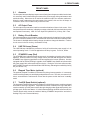
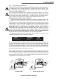
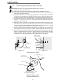
8. PREVENTIVE MAINTENANCE
PREVENTIVE MAINTENANCE
Maintenance should be performed every three months. If the power module fails to perform
a specific function, refer to the troubleshooting chart. By establishing a routine maintenance
program and following the guidelines contained in this manual, the AP Series power supply
will continue to provide years of trouble-free operation.
Care of the batteries should be the first step in any power supply maintenance program. In
addition to voltage checks, visually inspect the batteries for signs of cracks, leaks or swelling.
To aid in quick identification and tracing of voltages in the maintenance log, number the
batteries inside the enclosure using labels or masking tape, etc. Because of a battery’s
chemical composition, it is temperature sensitive and susceptible to over and undercharging. Since batteries behave differently in the winter than they do in the summer, Alpha
logic cards automatically compensate for changes in temperature by adjusting float and
equalize charge voltages.
SAFETY PRECAUTIONS
THE POWER SUPPLY SHOULD BE SERVICED ONLY BY QUALIFIED PERSONNEL.
USE A BUCKET TRUCK, OR SUITABLE SAFETY EQUIPMENT (SAFETY HARNESS AND
CLIMBING SPIKES), WHEN SERVICING POLE-MOUNT INSTALLATIONS.
USE HEAVY GLOVES WHEN HANDLING A POWER MODULE THAT HAS JUST BEEN
TAKEN OUT OF SERVICE. THE FERRORESONANT TRANSFORMER GENERATES
HEAT AND MAY CAUSE BURNS IF HANDLED WITH BARE HANDS.
NEVER ATTEMPT TO RECALIBRATE A LOGIC CARD IN THE FIELD, OTHER THAN
SETTING APM (REV. 8 OR HIGHER) BATTERY CHARGER VOLTAGE SWITCHES
(SECTION 6.8.2.1).
ALPHA TECHNOLOGIES IS NOT RESPONSIBLE FOR BATTERY DAMAGE DUE TO
IMPROPER CHARGER SETTINGS. REFER TO SECTION 6.8 AND CONSULT THE
BATTERY MANUFACTURER FOR CORRECT CHARGE VOLTAGE REQUIREMENTS.
WEAR EYE PROTECTION WHENEVER WORKING WITH BATTERIES.
ALWAYS SWITCH THE MODULE’S BATTERY BREAKER OFF, OR REMOVE THE FUSE,
BEFORE DISCONNECTING BATTERY CABLES.
Procedure:
8.1
Check Battery Terminals and Connecting Wires
Check each battery terminal and connection. Make sure the posts are clean and the crimped
connectors are tight. One major battery manufacturer suggests that terminal connectors be
torqued to 75 inch/pounds at installation and then re-torqued to 50 inch/pounds during routine
maintenance. If there is an “in-line” fuse in the battery cable, check the fuse holder and fuse.
Make sure the terminals are properly greased with an approved battery terminal corrosion
inhibitor such as NCP-2.
8.2
Check Battery Open Circuit Voltage
Switch the power module's front panel battery breaker to OFF, or remove the fuse.
Disconnect the negative (blue) battery cable from pin 1 on the module's 10-pin terminal strip.
CAUTION: Do not let the exposed end of the battery cable contact the chassis or the
enclosure. Measure the individual voltages across each battery. Differences greater than
0.3 VDC between any of the batteries may indicate a defective or marginal battery. Always
use an identical type of battery for replacement.
33