1
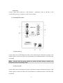
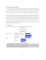
 SW10K SW10K
SW10K
SW10K •
Professional Reference Sub-Woofer Monitor •
User’s Manual
www.esi-pro.com
SW10K
CAUTION: TO REDUCE THE RISK OF ELECTRIC SHOCK,
DO NOT REMOVE COVER (OR BACK). NO USER SERVICEABLE
PARTS INSIDE. REFER SERVICING TO QUALIFIED SERVICE
PERSONNEL.
WARNING: TO PREVENT FIRE OR ELECTRIC SHOCK, DO NOT EXPOSE THIS
APPLIANCETO RAIN OR MOISTURE
CAUTION: TO PREVENT ELECTRIC SHOCK, DO NOT USE THIS (POLARISED)
PLUG WITH AN EXTENSION CORD, RECEPTACLE OR OTHER OUTLET
UNLESS THE BLADES CAN BE FULLY INSERTED TO PREVENT BLADE
NOTE: Some ESI products are equipped with dual or multi-voltage transformers
(which are indicated on the back panel). Before you plug in the power cord, please
check the AC voltage selector on the back panel of this product and make sure the
voltage selector is set correctly.
The lighting flash with arrowhead,
within an equilateral triangle, is
intended to alert the user of the
presence of uninsulated “dangerous
voltage” within the product’s enclosure;
that may be of sufficient magnitude to
constitute a risk of electric shock to
person
The exclamation point within an
equilateral triangle is intended to alert
the user of the presence of important
operating and maintenance (servicing)
instructions in the literature
accompanying the appliance.
CAUTION: The apparatus shall not be exposed to dropping or splashing and that
no objects filled with liquids, such as vases, shall be placed on the apparatus.
CAUTION: The apparatus shall not be exposed to dripping or splashing and that no objects
filled with liquids, such as vases, shall be placed on the apparatus.
2
Contents
Contents ....................................................................................................................................... 3
Introduction ................................................................................................................................. 4
SW10K Features.......................................................................................................................... 5
1.
Subwoofer...................................................................................................................... 5
2.
Enclosure ....................................................................................................................... 5
3.
Network & POWER AMPLIFIERS .............................................................................. 5
Installation ................................................................................................................................... 5
1.
Precautions..................................................................................................................... 5
2.
Exterior Features............................................................................................................ 6
1)
BALANCE A................................................................................................................. 6
2)
Balance B....................................................................................................................... 6
3)
Mute Control.................................................................................................................. 7
4)
Power LED & Volume Controller.................................................................................. 7
5)
Cross over Controller..................................................................................................... 7
6)
Phase Switch .................................................................................................................. 8
7)
Power Part...................................................................................................................... 8
8)
Power Connector............................................................................................................ 8
3.
Connecting to the satellite speakers............................................................................... 8
4.
Position of the Subwoofer in the Studio ........................................................................ 9
Technical Specifications ............................................................................................................ 10
END USER WARRANTY ........................................................................................................ 11
3
Introduction
Thank you for choosing SW10K, powerful sub-woofer monitor speaker for professional studio
applications and higher level home entertainment.
ESI has been building excellent reputation for digital interfaces and near Field monitor speaker
manufacturer. Now, after long research and development, SW10K is born to change the concept
of reference sub-woofer monitoring.
SW10K is designed and tested by several audio engineers to meet your needs in studio
monitoring environment. It is focused on its functionality-to deliver the pure original sound
without any add on.
SW10K is designed to overcome all the limitations of conventional reference sub-woofer
monitoring for digital audio environment. This system delivers complete subwoofer range of
frequency response by employing extra-ordinary driver and unique cross over technology
developed by ESI to go with monitor speakers in the markets.
From professional users in commercial studios to home studio owners, SW10K is true solution
for studio subwoofer monitoring in its own class.
4
SW10K Features
1. SUBWOOFER
Subwoofer unit is 10inch in diameter with mineral filled polypropylene cone with high
temperature voice coil and damped rubber surround. It is designed to deliver balanced
subwoofer response. Polypropylene is used to react against the input signal accurately and to
deliver even minimal input precisely minimizing distortion.
2. ENCLOSURE
Enclosure acts as important role as the other components. SW10K enclosure is designed to
endure impacts from inside under extreme conditions. It employs high-density special MDF and
unique interior reinforcement to provide more stable performance.
3. NETWORK & POWER AMPLIFIERS
Network & Power Amplifiers for SW10K are specially designed for its own subwoofer.
Network distributes subwoofer frequency properly to driver in order to reduce loss of sound and
distortion achieving natural balance of the sound.
In order to generate ultra crispy, powerful sound quality, there is special designed power
amplifier inside SW10K to drive Subwoofer driver by matching each parameter between
amplifier and driver. The power delivered to subwoofer driver at rated distortion is 100W.
Installation
1. PRECAUTIONS
Handling
Do not grab the speaker driver unit: SW10K is packaged in box fitted tight, so your attention is
required when taking speakers out of the box. To avoid the possible damage to the speaker
driver unit, hold both sides of the speaker to pull out of the box. The speaker driver unit should
not be touched to avoid the damage even after it is out of the box.
Recommend to use high quality balanced or unbalanced cable for input connection.
Turn off the power of SW10K and turn Volume Control of SW10K to minimum before
connection.
5
Connection
Connect L&R XLR balanced or TRS balanced / unbalanced input of SW10K to the
corresponding pre-amp, computer or game console outputs.
2. EXTERIOR FEATURES
1) BALANCE A
Connect Male side of XLR Balanced Cables to the balanced inputs and balanced output to left
satellite speaker. Connect the Male side of TRS balanced or unbalanced cables to the TRS input
of SW10K.
Note: Assure that the power switch is turned off and Volume control is to
minimum before connecting cable.
2) BALANCE B
Connect Male side of XLR Balanced Cables to the balanced inputs and balanced output to right
satellite speaker. Connect the Male side of TRS balanced or unbalanced cables to the TRS input
of SW10K.
6
Note: Assure that the power switch is turned off and Volume control is to
minimum before connecting cable.
3) MUTE CONTROL
This connector allows you to connect a expression pedal that you can use to mute the subwoofer
sound. This is helpful if you want to make A/B comparison of the sound with and without
subwoofer and you can quickly control it with a simple pedal.
4) POWER LED & VOLUME CONTROLLER
LED: Power ON (Red)/ Protection (Red) /Operation(Green)
Volume Controller: With control the volume of the subwoofer is set to properly match the
satellite speakers. You can start with setting at 12 O’clock position of Control.
If the Subwoofer is placed on the floor against one wall in a normal room, the Subwoofer sound
pressure could be increased 3dB than placed on the freestanding floor. On the other hand, if the
Subwoofer is placed in a corner, the Subwoofer sound pressure could be increased by another
3dB comparing to placing on the floor against one wall. You can use the Level control to set the
Sound Pressure of Subwoofer under different placements to match Satellite sound pressure
properly.
5) CROSS OVER CONTROLLER
With the control, “CROSSOVER”, an adjustable, 2nd order (12 dB/Octave) low-pass filter
gives an upper limit between 50 and 180 Hz.
If the Subwoofer SW10K connected to Professional Audio Console with Bass management, the
Subwoofer control should be set to 180 Hz as the crossover will be handled by the Console. (Or
the filter of SW10K will add together with the filter of Console and generate wrong frequency
response at crossover area.
If the subwoofer SW10K connected to Professional Audio Console without Bass management,
the Subwoofer control should be set together with low frequency limit of Satellite Control.
7
6) PHASE SWITCH
The purpose of this control is to match the phase of satellite cut off frequency to the phase of the
upper frequency limit of the Subwoofer. Adjust the Phase control to make the maximum sound
pressure at cross over frequency in order to make sure Subwoofer and Satellites are in phase at
cross over frequency. So, you will get maximum sound pressure and most accurate sound
quality from the whole system.
7) POWER PART
Please only replace with the exactly same type of fuse in the fuse holder. And you can select
either 110V or 230V AC power according to your requirement.
8) POWER CONNECTOR
It is connector for plugging to detachable 3 circuit line cord.
3. CONNECTING TO THE SATELLITE SPEAKERS
Subwoofer SW10K can be connected to your Professional Audio system in two different ways:
a. Connect SW10K Left or Right Input to Subwoofer output of Professional Audio
Console with Bass Management.
Professional Audio Console
(With Base Management)
Satellite-L
Input
Subwoofer
L or R Input
Satellite-Left
Satellite-R
Input
Satellite-Right
SW10K
8
Connect the Professional Audio Console Subwoofer output to either L or R Input of SW10K
through XLR or TRS connector.
b. Connect SW10K Left and Right Inputs to Professional Audio Console without Bass
Management.
Professional Audio Console
(Without Base Management)
Output-L Output-R
Input
Input-L
Input-R
Output-L
Input
Output-R
Satellite-Left
Satellite-Right
SW10K
Connect the Professional Audio Console Left and Right Outputs to SW10K Input-L and
Input-R respectively through XLR or TRS connectors. Then, connect SW10K Output-L and
Output-R to Left and Right Satellites respectively through XLR connectors.
4. POSITION OF THE SUBWOOFER IN THE STUDIO
In theory, the best position for Subwoofer is midway between the satellite speakers, with its
front facing forward and in the same plane as the fronts of the satellite speakers.
Subwoofer SW10K may, however, due to the very low distortion by design, so there is no
directional sound field from SW10K, in practice be moved quite far from this position without
any detrimental effect on the sound reproduction.
Different positions of the Subwoofer related to walls will affect its efficiency, and the room
influence on the frequency response. This can be compensated for by readjusting the filter
settings.
9
Technical Specifications
- Type: Powered Subwoofer
-Subwoofer Driver: 10" black paper cone with high temperature voice coil and damped
rubber surround.
- Frequency Response: 30Hz - 180Hz, Adjustable 50Hz – 180Hz
- Amplifier Power: 100W@100Hz, 4 ohm, 0.1% THD
- Dynamic Power: 120W
- S/N Ratio: >100dB below full output
- Input Connectors: 2 x XLR R/L Balanced Input Connector
2 x TRS Balanced/ Unbalanced Input Connector
-Output Connectors: 2x XLR Balanced output for Satellites
1x XLR Balanced output for Extra Sub
- Controls : Level, Phase, Subwoofer Frequency, Satellite Frequency
- Switches : Power On/Off slide switch,
L&R XLR Outputs “HPF Bypass” On/Off Slide Switch.
- Input Impedance: 20K ohms balanced, 10K ohms unbalanced
- Input Sensitivity: 150 mV input produces full output with Input Sensitivity control at
maximum.
-Protection: over temperature, shorting, an external main fuses.
- Indicators: Power ON (Red)/ Protection (Red) /Operation(Green)
- Power Requirements: Factory programmed for either 115V ~50/60Hz,
230V~50/60Hz or 100V~50/60Hz;
Power via detachable 3 circuit line cord.
- Cabinet: vinyl laminated MDF
- Dimension (unit): 384mm(H) x 354mm(W) x 384mm(D)
- Dimension (Shipping Carton): 492mm(H) x 488mm(W) x 458mm(D)
- Net Weight: 12.5 Kg (27.5 lbs) /unit (without packing)
- Shipping Weight: 16.5 Kg (36 lbs) /unit (with shipping carton)
Remarks: Above specifications are subject to change without notice.
10
END USER WARRANTY
Trademarks
ESI and SW10K are trademarks of EGOSYS, Inc. Windows is a trademark of Microsoft Corporation. Apple, Mac,
Macintosh are trademarks of Apple Computer, Inc. Other product and brand names are trademarks or registered
trademarks of their respective companies.
End User Warranty
EGOSYS, Inc. (ESI) warrants this product, under normal use, to be free of defects in materials and workmanship for a
period of One(1) year from date of purchase, so long as: the product is owned by the original purchaser, with proof of
purchase from an authorized ESI dealer. This warranty explicitly excludes power supplies and included cables which
may become defective as a result of normal wear and tear.
In the event that ESI receives, from an original purchaser and within the warranty coverage period, written notice of
defects in materials or workmanship, ESI will either replace the product, repair the product, or refund the purchase at its
option. To obtain warranty service, the original purchaser or his authorized dealer must fill the support contact form at
http://www.esi-pro.com. In the event repair is required, shipment to and from ESI and possible handling charges shall be
borne by the purchaser. ESI will not accept returns without prepaid shipments. In the event that repair is required, a
Return Authorization Number must be obtained from ESI. After this number is obtained, the unit should be shipped back
to ESI in a protective package with a description of the problem and the Return Authorization Numer clearly written on
the package. All such returns must be shipped to EGOSYS, Inc. headquarters in Seoul, Korea (or US Office).
In the event that ESI determines that the product requires repair because of user misuse or regular wear, it will assess a
fair repair or replacement fee. The customer will have the option to pay this fee and have the unit repaired and returned,
or not pay this fee and have the unit returned and un-repaired.
The remedy for breach of this warranty shall not include any other damages. ESI will not be liable for consequential,
special, indirect, or similar damages or claims including loss of profit or any other commercial damage, even if its agents
have been advised of the possibility of such damages, and in no event will ESI’s liability for any damages to the
purchaser or any other person exceed the price paid for the product., regardless of any form of the claim. ESI
specifically disclaims all other warranties, expressed or implied. Specifically, ESI makes no warranty that the product is
fit for any particular purpose.
11
The FCC and CE Regulation Warning
This device complies with Part 15 of the FCC Rules. Operation is subject to the following two conditions: (1) this device
may not cause harmful interference, and (2) this device must accept any interference received, including interference
that may cause undesired operation. Caution: Any changes or modifications in construction of this device with are not
expressly approved by the party responsible for compliance, could void the user's authority to operate equipment.
NOTE: This equipment has been tested and found to comply with the limits for a Class A digital device, pursuant to Part
15 of the FCC Rules. These limits are designed to provide reasonable protection against harmful interference when the
equipment is operated in a commercial environment. This equipment generates, uses, and can radiate radio frequency
energy and, if not installed and used in accordance with the instruction manual, may cause harmful interference to radio
communications. Operation of this equipment in a residential area is likely to cause harmful interference in which case
the user will be required to correct the interference at his own expense. If necessary, consult an experienced
radio/television technician for additional suggestions.
Correspondence
For technical support inquiries, contact your nearest dealer, local ESI distributor or ESI directly at:
EGOSYS, Inc.
6-9, Yongmoon-dong, Yongsan-gu
Seoul, KOREA, 140-832
www.esi-pro.com
Technical Support:
Sales:
Online Support Community
www.esiforum.com
North and South America (English)
[email protected]
UK (English)
[email protected]
Germany (German)
[email protected]
International
[email protected]
USA
[email protected]
Germany
[email protected]
·
All features and specifications subject to change without notice.
·
Parts of this manual are continually being updated. Please check our web site www.esipro.com occasionally for the most recent update information.
12
SAFETY INSTRUCTION
1. READ INSTRUCTIONS
All the safety and operating instructions should be read
before the appliance is operated.
2. RETAIN INSTRUCTIONS
The safety and operating instructions should be retained
for future reference.
3. HEED WARNINGS
All warnings on the appliance and in the operating
instructions should be adhered to.
4. FOLLOW INSTRUCTIONS
from the outlet when left unused for a long period of time.
14. OBJECT AND LIQUID ENTRY
Care should be taken so that objects do not fall and
liquids are not spilled into the enclosure through
openings.
15. SERVICING
The user should not attempt to service the appliance
beyond that described in the operating instructions. All
other servicing should be referred to qualified service
personnel.
All operating and use instructions should be followed.
5. WATER AND MOISTURE
The appliance should not be used near water – for
example, near a bathtub, washbowl, kitchen sink,
laundry tub, in a wet basement, or near a swimming pool,
etc.
6. CART AND STAND
The appliance should be used only with a cart or stand
that is recommended by the manufacturer.
6A. An appliance and cart combination
should be moved with care. Quick stop,
excessive force, and uneven surface
may cause the appliance and cart
combination to overturn.
7. WALL OR CEILING MOUNTING
This equipment is not designed for use mounted on a
wall or a ceiling.
8. VENTILATION
The appliance should be situated so that its location or
position does not inference with its proper ventilation.
For example, the appliance should not be situated on a
bed, sofa, rug, or similar surface that may block the
ventilation openings, or placed in a built-in installation,
such as bookcase or cabinet that may impede the flow of
air through the ventilation openings.
9. HEAT
The appliance should be situated away from heat
sources such as radiators, heat registers, stoves, or
other appliances (including amplifiers) that produce heat.
10. POWER SOURCES
The appliance should be connected to a power supply
only of the type described in the operating instructions or
as marked on the appliance.
11. POWER – CORD PROTECTION
Power-supply cords should be routed so that they are
not likely to be walked on or pinched by items placed
upon or against them, paying particular attention to cords
at plugs, convenience receptacles, and the point where
they exist from the appliance.
12. CLEANING
The appliance should be cleaned only as recommended
by the manufacturer.
13. NON USE PERIODS
The power cord of the appliance should be unplugged
16. DAMAGE REQUIRING SERVICE
The appliance should be serviced by qualified service
personnel when:
a) The power-supply cord or the plug has been
damaged; or
b) Objects have fallen, or liquid has been spilled
into the appliance; or
c) The appliance has been exposed to rain; or
d) The appliance does not appear to operate
normally or exhibits a marked change in
performance; or
e) The appliance has been dropped, or the
enclosure is damaged.
17. POWER LINES
(APPLIES FOR TUNER AND RECEIVERS ONLY)
An outdoor antenna should be located away from power
lines.