1
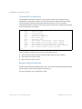
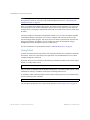
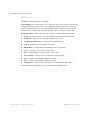
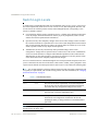
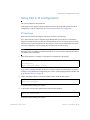
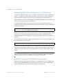
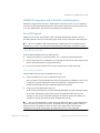
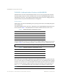
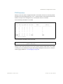
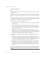
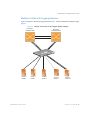
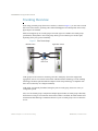
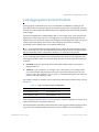
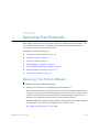
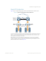
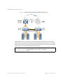
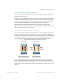
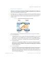
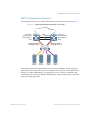
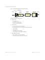
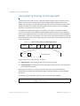
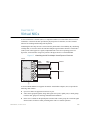
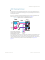
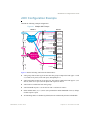
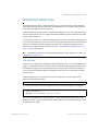
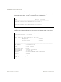
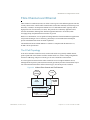
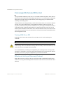
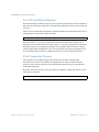
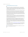
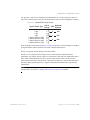
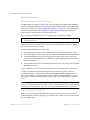
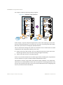
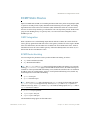
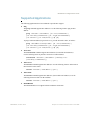
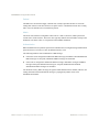
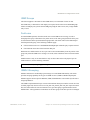
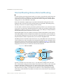
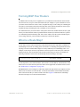
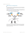
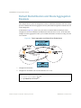
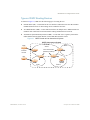
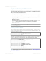
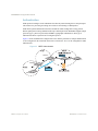
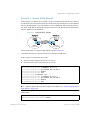
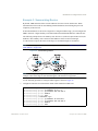
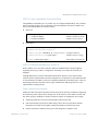
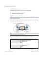
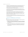
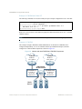
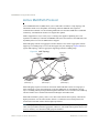
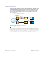
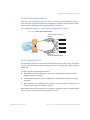
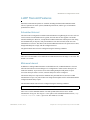
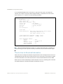
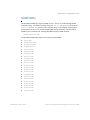
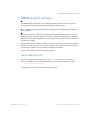
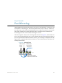
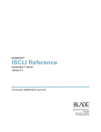
BLADEOS 6.5.2 Application Guide
Example of Subnet Routing
Consider the role of the G8124 in the following configuration example:
Figure 25 Switch-Based Routing Topology
Default router:
205.21.17.1
IF 1
VLAN 1
IF 2
VLAN 2
IF 4
VLAN 4
IF 3
VLAN 3
Server subnet 3:
206.30.15.2-254
Server subnet 1:
100.20.10.2-254
Server subnet 2:
131.15.15.2-254
The switch connects the Gigabit Ethernet and Fast Ethernet trunks from various switched subnets
throughout one building. Common servers are placed on another subnet attached to the switch. A
primary and backup router are attached to the switch on yet another subnet.
Without Layer 3 IP routing on the switch, cross-subnet communication is relayed to the default
gateway (in this case, the router) for the next level of routing intelligence. The router fills in the
necessary address information and sends the data back to the switch, which then relays the packet to
the proper destination subnet using Layer 2 switching.
With Layer 3 IP routing in place on the switch, routing between different IP subnets can be
accomplished entirely within the switch. This leaves the routers free to handle inbound and
outbound traffic for this group of subnets.
BMD00220, October 2010
Chapter 15: Basic IP Routing 221