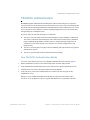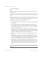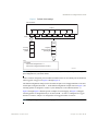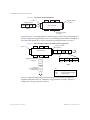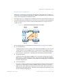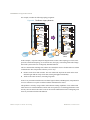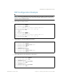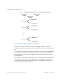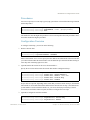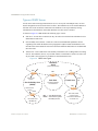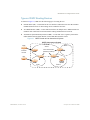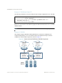
1
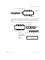
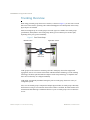
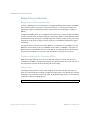
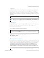
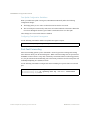
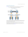
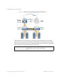
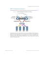
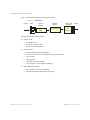
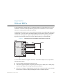
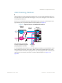
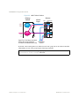
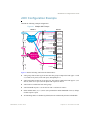
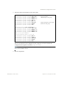
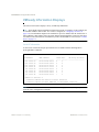
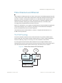
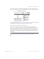
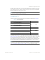
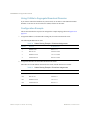
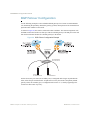
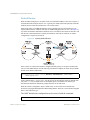
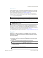
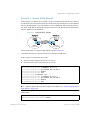
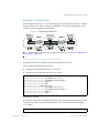
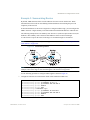
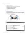
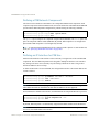
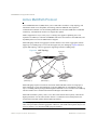
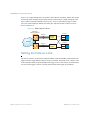
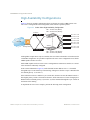
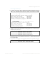
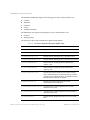
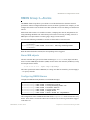
BLADEOS 6.5.2 Application Guide
Switch-Centric Configuration
STP/PVST+ is switch-centric: STGs are enforced only on the switch where they are configured.
The STG ID is not transmitted in the Spanning Tree BPDU. Each Spanning Tree decision is based
entirely on the configuration of the particular switch.
For example, in Figure 12, though VLAN 2 is shared by the Switch A and Switch B, each switch is
responsible for the proper configuration of its own ports, VLANs, and STGs. Switch A identifies its
own port 17 as part of VLAN 2 on STG 2, and the Switch B identifies its own port 8 as part of
VLAN 2 on STG 2.
Figure 12 Implementing Multiple Spanning Tree Groups
Chassis
Switch A
Application
Switch B
17
STG 2
8
VLAN 2
18
2
STG 2
VLAN 3
8
1
STG 1
VLAN 1
2
1
1
Application
Switch C
8
Application
Switch D
The VLAN participation for each Spanning Tree Group in Figure 12 on page 121 is as follows:
VLAN 1 Participation
Assuming Switch B to be the root bridge, Switch B transmits the BPDU for VLAN 1 on ports
1 and 2. Switch C receives the BPDU on port 2, and Switch D receives the BPDU on port 1.
Because there is a network loop between the switches in VLAN 1, either Switch D will block
port 8 or Switch C will block port 1, depending on the information provided in the BPDU.
VLAN 2 Participation
Switch B, the root bridge, generates a BPDU for STG 2 from port 8. Switch A receives this
BPDU on port 17, which is assigned to VLAN 2, STG 2. Because switch B has no additional
ports participating in STG 2, this BPDU is not forwarded to any additional ports and Switch B
remains the designated root.
VLAN 3 Participation
For VLAN 3, Switch A or Switch C may be the root bridge. If Switch A is the root bridge for
VLAN 3, STG 2, then Switch A transmits the BPDU from port 18. Switch C receives this
BPDU on port 8 and is identified as participating in VLAN 3, STG 2. Since Switch C has no
additional ports participating in STG 2, this BPDU is not forwarded to any additional ports and
Switch A remains the designated root.
BMD00220, October 2010
Chapter 8: Spanning Tree Protocols 121