1
SAFETY PRECAUTIONS
(Please read it carefully before using this product)
Before using this product, please read carefully the manual and its related manuals introduced thereinafter,
and pay full attention to the safety to handle the product correctly.
The instructions given in this manual are concerned with this product.
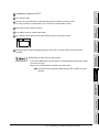
In this manual, the safety instructions are ranked as "DANGER" and "CAUTION".
DANGER
Indicates that incorrect handling may cause hazardous conditions,
resulting in death or severe injury.
CAUTION
Indicates that incorrect handling may cause hazardous conditions,
resulting in medium or slight personal injury or physical damage.
Note that the
CAUTION level may lead to serious consequences according to the circumstances.
Always follow instructions of both levels because they are important to personal safety.
[Test operation precautions]
DANGER
Please read this manual carefully and understand it thoroughly before executing system monitor,
special module monitor, and circuit monitor (bit device on/off, current value change of word device,
setting value of timer/counter and current value change, and current value change of buffer
memory) During test operation, DO NOT change the devices data that are used to execute
important system operations.
Mis-output or mis-operation may cause accidents.
A-1
Cautions for using this software
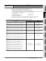
1. Required PC memory
The processing may be terminated by Windows on a personal computer of which main memory capacity
is less than 64M bytes. Make sure to secure the capacity of 64 M bytes or more.
2. Free capacity of hard disk (virtual memory)
At least 100M bytes of free capacity of virtual memory should be secured within hard disk to run this
software.
The processing may be terminated by Windows if 100M bytes or more of free space cannot be secured
within hard disk while running GT Designer.
Secure enough free capacity of virtual memory within hard disk space in order to run the software.
When enough free capacity cannot be secured, make sure to save projects frequently.
3. Error messages displayed while starting and editing
"Operation will be terminated because of insufficient memory. Would you like to stop?"
If the above message appears, close other running application software or reboot Windows in order to
secure at least 50M bytes of free hard disk space.
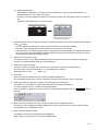
4. GT Designer2 and GOT display
(a) Cautions for displaying straight line other than full line (dotted line, for example) in Bold
When straight line other than full line is drawn in bold, the line may not be displayed with its actual line
width on a personal computer. However, it will be displayed correctly on GOT. This phenomenon does
not mean data problem.
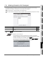
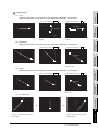
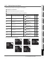
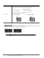
(b) Display of end points of straight line/line freeform/polygon
As shown below, the end points of straight line/line freeform/polygon are displayed differently between
GT Designer2 and GOT.
On GT Designer 2
On GOT
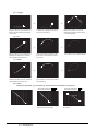
(c) Start position for filling patterns
Some filling patterns may be differently displayed. For example, the start position may be different
between GT Desginer2 and GOT.
(d) Drawing of different type lines
The length of the dots varies in different dotted lines (for example: the chain lines).
(e) Display of object
The display position of the memory data display in graph function is different between GT Designer2
and GOT.
Even if the display-start-line of a comment has been set, the comment will be displayed from the first
line on GT Designer2.
A-2
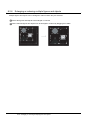
(f)
Display magnification
When display magnification is changed, the connected lines or figures may be separated or the
filled-paint may be out of outline of the figure.
However, if they are displayed correctly on the preview screen, they will appear correctly on GOT as
well.
(Example): When filled-paint is out of the outline.
Display magnification: 200%
Display magnification: 100%
Position of Paint mark may be
shifted and the filled-paint may
be out of the figure outline.
5. Restrictions when the color setting is changed to the setting of less colors in the system environment (256
colors
2 colors)
• The color palette for setting color will be changed according to the updated settings.
• The color on the drawing screen will be kept the same as prior to the change.
If the color setting for a [red] rectangle-figure is changed to the 2 colors (B/W), the [red] color will remain.
• The colors of the image data (BMP format file) will be reduced when the project is stored, the screen is
closed and that image data is double-clicked.
6. Object function and device type
The object (bit lamp or word lamp),for which bit device setting and word device setting are separated,
cannot be converted between bit device and word device.
7. When device type is changed
Confirm the device type when the set bit device is changed from bit device into word device.
The device flag may be represented as "??", depending on the settings .
(Example) D0. b0
D0
D0.b5
??
8. OS setting
Set the font size as "Small Font" when setting OS (Windows ) screen.
The GT designer2 dialog box cannot be displayed correctly if the font size is set as "Large font".
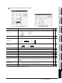
9. When the toolbar icon appears in smaller size after startup of GT Desinger2
The toolbar icon may appear in smaller size right after GT Deseiger2 is started up.
To correctly display the icon, initialize it as instructed below.
(Click on [Project]
that tab.)
[References] from the menu, and select the toolbar tab. Click on Reset All button in
10. When using GT Designer2 in the PC in which the OS other than Japanese version
The text may not be displayed correctly depending on the OS versions; some version include the fonts
incompatible with GT Designer2 or GOT.
11. When using Microsoft Narrator
GT Designer2 cannot be used with Microsoft Narrator.
When using GT Designer2, do not use Microsoft Narrator.
A-3
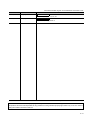
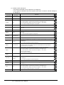
REVISIONS
*The manual number is given on the left bottom of the back cover.
Print Date
Manual Number
Oct., 2004
SH (NA)-080521ENG-A
Mar., 2005
SH (NA)-080521ENG-B
Revision
First edition
Partial corrections
Section 2.1.2, 3.1.1, 3.1.2, 3.2, 3.4.1, 3.6, 4.3.1, 4.7.1, 4.10.1, 4.11.1, 4.11.2,
4.12, 5.2.3, 5.2.4, 5.2.5, 5.3.1, 5.3.2, 6.1.2, 7.1, 7.1.2, 7.2, 7.3,
7.3.2 to 7.3.7, 8.1.2, 9.1.4, 9.2.1, 9.4.1, Appendix 2
Additions
Section 1.2.1, 1.2.2, 7.3.8
Oct., 2005
SH (NA)-080521ENG-C
Partial corrections
Section 1.2, 1.2.2, 3.1.2, 3.4.2, 3.4.3, 3.2, 3.6, 4.1, 4.2, 4.7.4, 4.7.5, 4.10,
4.10.1, 4.10.2, 4.12, 4.13, 6.1.2, 7.1.1, 7.1.2, 7.2, 7.3.1, 7.3.2, 7.3.3, 7.3.4,
7.3.5, 7.3.6, 7.3.7, 7.3.8, 8.1.3, 9.1.4, 9.3
Janu., 2006
SH (NA)-080521ENG-D
Jun., 2006
SH (NA)-080521ENG-E
Partial corrections
Section 4.7, Section 6.1, Section 9.1
Partial corrections
Section 4.2, Section 4.3.1, Section 4.7.1, Appendix 3.1
Additions
Section 8.2.6
Nov., 2006
SH (NA)-080521ENG-F
Partial corrections
Section 1.2, Section 3.1, Section 3.2, Section 3.3, Section 3.4, Section 4.7,
Section 4.9, Section 4.11, Section 7.3, Section 9.1, Appendix 1
Additions
Section 8.1.4
Dec., 2006
SH (NA)-080521ENG-G
Partial corrections
Section 4.3.1, Section 4.14.2
Feb., 2007
SH (NA)-080521ENG-H
Partial corrections
Section 3.4.3
May., 2007
SH (NA)-080521ENG-I
Partial corrections
Section 1.2.1, 3.1.1, 3.2, 3.3.1, 3.4.1, 3.4.3, 4.7.4, 4.9, 4.11.1, 4.11.2, 5.1.2,
5.2.2, 5.2.3, 5.2.6, 5.3.2, 7.1.1, 7.2, 7.3.1, 7.3.2, 7.3.3, 7.3.4, 7.3.6, 7.3.7,
7.3.8, Appendix 2
Aug., 2007
SH (NA)-080521ENG-J
Partial corrections
Section 3.4.3, 4.1, 4.6.1, 5.1.2, 5.2.2
Dec., 2007
SH (NA)-080521ENG-K
Partial corrections
Section 2.1.2, 3.2, 4.7.4, 9.1.5, 9.6.2, Appendix 2
Feb., 2008
SH (NA)-080521ENG-L
Jun., 2008
SH (NA) -080521ENG-M
Partial corrections
Section 8.1.4, 8.1.5
Partial corrections
Sections 2.1.2, 3.6
A-4
*The manual number is given on the left bottom of the back cover.
Print Date
Manual Number
Oct., 2008
SH (NA)-080521ENG-N
Revision
Partial corrections
Section 2.1, 3.2, 3.3, 3.4, 8.2, 9.1
Mar., 2009
SH (NA)-080521ENG-O
Partial corrections
Section 4.10, 3.2, Appendix 3
Japanese Manual Version SH-080514-Q
This manual confers no industrial property rights or any other kind, nor does it confer any patent licenses. Mitsubishi Electric
Corporation cannot be held responsible for any problems involving industrial property rights which may occur as a result of
using the contents noted in this manual.
© 2004 MITSUBISHI ELECTRIC CORPORATION
A-5
INTRODUCTION
Thank you for choosing Mitsubishi Graphic Operation Terminal (Mitsubishi GOT).
Read this manual and make sure you understand the functions and performance of the GOT thoroughly
in advance to ensure correct use.
CONTENTS
SAFETY PRECAUTIONS............................................................................................... A - 1
Cautions for using this software ..................................................................................... A - 2
REVISIONS .................................................................................................................... A - 4
INTRODUCTION ............................................................................................................ A - 6
CONTENTS.................................................................................................................... A - 6
Function Quick Reference ............................................................................................ A - 10
Manuals ........................................................................................................................ A - 18
ABBREVIATIONS AND GENERIC TERMS ................................................................. A - 19
How to Use This Manual .............................................................................................. A - 23
Product List................................................................................................................... A - 24
1. OVERVIEW...................................................... 1 - 1 to 1 - 7
1.1 Overview...................................................................................................................1 - 1
1.2 Feature .....................................................................................................................1 - 3
1.2.1 Easy-to-use operations.................................................................................................................1 - 3
1.2.2 Useful functions ............................................................................................................................1 - 5
2. SYSTEM CONFIGURATION ........................... 2 - 1 to 2 - 6
2.1 System Configuration in Creating Monitor Screen ...................................................2 - 1
2.1.1 System configuration ....................................................................................................................2 - 1
2.1.2 Operating environment .................................................................................................................2 - 1
2.2 System Configuration of Data Transfer and Document Creation .............................2 - 3
2.2.1 System configuration ....................................................................................................................2 - 3
2.2.2 RS-232 cable to be used ..............................................................................................................2 - 5
3. SCREEN CONFIGURATION OF GT DESIGNER 2
....................................................................... 3 - 1 to 3 - 36
3.1 Screen Configuration and Basic Operation ..............................................................3 - 1
3.1.1 Screen configuration and various tools ........................................................................................3 - 1
3.1.2 Operation of workspace................................................................................................................3 - 4
3.2 Menu Configuration ..................................................................................................3 - 8
3.3 Toolbars..................................................................................................................3 - 11
3.3.1 Types of toolbars ........................................................................................................................3 - 11
A-6
3.4 Customizing Screen Configuration and Toolbars................................................... 3 - 19
3.4.1
3.4.2
3.4.3
3.4.4
3.4.5
Customizing screen configuration............................................................................................... 3 - 20
Customizing toolbars .................................................................................................................. 3 - 22
Customizing GT Designer2 operating environment.................................................................... 3 - 26
Display with frame ...................................................................................................................... 3 - 32
Redisplaying drawing screen...................................................................................................... 3 - 33
3.5 How to use Help..................................................................................................... 3 - 34
3.6 How to View the Product Information..................................................................... 3 - 36
4. CREATING AND EDITING SCREEN ............ 4 - 1 to 4 - 58
4.1 Selecting Project at the Start of GT Designer2 ........................................................ 4 - 1
4.2 Creating a New Project ............................................................................................ 4 - 3
4.3 Opening/Closing Project .......................................................................................... 4 - 9
4.3.1 Opening project ............................................................................................................................ 4 - 9
4.3.2 Closing project ............................................................................................................................ 4 - 11
4.4 Setting the Project Title .......................................................................................... 4 - 12
4.5 Creating a New Screen .......................................................................................... 4 - 13
4.6 Opening/Closing Screen ........................................................................................ 4 - 17
4.6.1 Opening screen .......................................................................................................................... 4 - 17
4.6.2 Closing screen ............................................................................................................................ 4 - 21
4.7 Basic Operations of Drawing Screen (Editor) ........................................................ 4 - 22
4.7.1
4.7.2
4.7.3
4.7.4
4.7.5
Object placement area and display area on GOT ...................................................................... 4 - 22
Basic operations for object placement........................................................................................ 4 - 24
Figure drawing/text input ............................................................................................................ 4 - 26
Object function setting ................................................................................................................ 4 - 28
Basic operations of dialog box.................................................................................................... 4 - 36
4.8 Operating Multiple Screens .................................................................................... 4 - 38
4.8.1 Cascading/tiling screens............................................................................................................. 4 - 38
4.8.2 Making editing screen active ...................................................................................................... 4 - 39
4.9 Changing Screen Property..................................................................................... 4 - 40
4.10 Viewing Created Screen Image ........................................................................... 4 - 43
4.10.1Previewing the Base Screen...................................................................................................... 4 - 43
4.10.2Previewing the Base Screen with window ................................................................................. 4 - 46
4.11 Copying/Deleting Screen .................................................................................... 4 - 48
4.11.1Copying screen data ................................................................................................................. 4 - 48
4.11.2Deleting screen data .................................................................................................................. 4 - 50
4.12 Setting Screen Switching Device ......................................................................... 4 - 52
4.13 Data Check .......................................................................................................... 4 - 54
4.14 Saving Project ...................................................................................................... 4 - 56
4.14.1Overwriting and saving project................................................................................................... 4 - 56
4.14.2Saving as project name ............................................................................................................. 4 - 56
4.15 Ending GT Designer2........................................................................................... 4 - 58
5. DATA TRANSFER OPERATION ................... 5 - 1 to 5 - 39
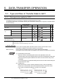
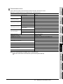
5.1 Type and Size of Transfer Data to GOT .................................................................. 5 - 1
5.1.1 Data type to be installed on GOT ................................................................................................. 5 - 1
5.1.2 Memory space required for data transfer...................................................................................... 5 - 8
A-7
5.2 Transferring data with RS-232 cable ......................................................................5 - 13
5.2.1
5.2.2
5.2.3
5.2.4
5.2.5
5.2.6
5.2.7
Setting communication ...............................................................................................................5 - 18
Getting built-in memory information ...........................................................................................5 - 19
Uploading....................................................................................................................................5 - 20
Installing ROM_BIOS..................................................................................................................5 - 21
Installing OS ...............................................................................................................................5 - 24
Downloading monitor data .........................................................................................................5 - 26
Downloading special data ..........................................................................................................5 - 28
5.3 Transferring Data Using Memory Card...................................................................5 - 29
5.3.1 Installing ROM_BIOS..................................................................................................................5 - 31
5.3.2 Transferring OS, monitor data and special data .........................................................................5 - 34
5.4 Error Message for Data Transfer............................................................................5 - 37
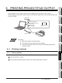
6. PRINTING PROJECT/FILE OUTPUT............ 6 - 1 to 6 - 14
6.1 Printing method ........................................................................................................6 - 1
6.1.1 Setting method..............................................................................................................................6 - 1
6.1.2 Setting items ................................................................................................................................6 - 2
6.2 Printing example ......................................................................................................6 - 9
6.2.1 Printer output ...............................................................................................................................6 - 9
6.2.2 File output ..................................................................................................................................6 - 13
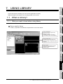
7. USING LIBRARY ........................................... 7 - 1 to 7 - 21
7.1 What is Library?........................................................................................................7 - 1
7.1.1 What you need to know before using library ................................................................................7 - 1
7.1.2 Basic operation of library .............................................................................................................7 - 4
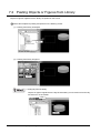
7.2 Pasting Objects or Figures from Library ...................................................................7 - 6
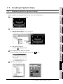
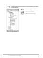
7.3 Creating Original Library...........................................................................................7 - 7
7.3.1
7.3.2
7.3.3
7.3.4
7.3.5
7.3.6
7.3.7
7.3.8
Registering objects or figures on library .......................................................................................7 - 7
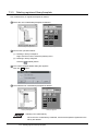
Copying registered library/template ..............................................................................................7 - 9
Deleting registered library/template ............................................................................................7 - 10
Editing registered objects and figures.........................................................................................7 - 11
Changing library property ...........................................................................................................7 - 13
Saving library ..............................................................................................................................7 - 14
Loading library from file ..............................................................................................................7 - 17
Importing user library ..................................................................................................................7 - 19
7.4 Utilizing Panelkit of GT Designer............................................................................7 - 21
8. DRAW AND EDIT .......................................... 8 - 1 to 8 - 34
8.1 Drawing Figures .......................................................................................................8 - 1
8.1.1
8.1.2
8.1.3
8.1.4
8.1.5
A-8
Drawing figures.............................................................................................................................8 - 1
Entering text .................................................................................................................................8 - 6
Painting figures .............................................................................................................................8 - 8
Capture function .........................................................................................................................8 - 10
Pasting figure data of BMP file ...................................................................................................8 - 13
8.2 Editing Figure and Object....................................................................................... 8 - 18
8.2.1 Selecting figure and object ......................................................................................................... 8 - 18
8.2.2 Editing figures and objects.......................................................................................................... 8 - 20
8.2.3 Grouping/Ungrouping multiple figures and objects..................................................................... 8 - 21
8.2.4 Undo and redo ............................................................................................................................ 8 - 21
8.2.5 Aligning figures and objects........................................................................................................ 8 - 22
8.2.6 Enlarging or reducing multiple figures and objects ..................................................................... 8 - 27
8.2.7 Changing attributes of figures and objects ................................................................................. 8 - 28
8.2.8 Changing size of figures/objects................................................................................................. 8 - 30
8.2.9 Copying figures and objects consecutively................................................................................. 8 - 32
8.2.10Copying figures and objects....................................................................................................... 8 - 34
9. USEFUL FUNCTIONS ................................... 9 - 1 to 9 - 39
9.1 Edit Function ............................................................................................................ 9 - 1
9.1.1
9.1.2
9.1.3
9.1.4
9.1.5
9.1.6
Batch setting of multiple objects/figures on the same screen (Property sheet) ............................ 9 - 1
Batch setting and managing objects/figures for each purpose (Category workspace)................. 9 - 5
Batch editing attributes of objects/figures scattered on multiple screens (Batch edit)................ 9 - 12
Simple selection of overlapped figure (Data view)...................................................................... 9 - 16
Checking devices in use (Device List) ........................................................................................ 9 - 17
Checking Text in use (Text String List)....................................................................................... 9 - 19
9.2 Referring to Device Comment When Setting Devices ........................................... 9 - 21
9.2.1 Importing device comment.......................................................................................................... 9 - 21
9.2.2 Check method of device comment ............................................................................................. 9 - 23
9.3 Checking Monitor Data for Errors........................................................................... 9 - 25
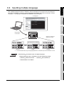
9.4 Inputting multiple language .................................................................................... 9 - 26
9.4.1 Input method............................................................................................................................... 9 - 27
9.4.2 Precautions................................................................................................................................. 9 - 33
9.5 Confirming the created data size ........................................................................... 9 - 34
9.5.1 Confirmation method .................................................................................................................. 9 - 34
9.5.2 Confirmation items...................................................................................................................... 9 - 34
9.6 Utilizing other project data...................................................................................... 9 - 35
9.6.1 Importing data............................................................................................................................. 9 - 35
9.6.2 Cautions...................................................................................................................................... 9 - 36
APPENDIX ............................................... App - 1 to App - 15
Appendix 1
List of Shortcut Keys .......................................................................................................App- 1
Appendix 2
Q&A of GT Designer2 Operation ....................................................................................App- 3
Appendix 3
Using Existing Data .........................................................................................................App- 6
Appendix 3.1 Outline procedures.......................................................................................................App- 6
Appendix 3.2 Precautions ..................................................................................................................App- 7
Appendix 4
Applicable Monitor Data ................................................................................................ App- 11
Appendix 4.1 Opening monitor data ................................................................................................ App- 12
Appendix 4.2 Uploading monitor data..............................................................................................App- 12
Appendix 4.3 Downloading monitor data ......................................................................................... App- 13
Appendix 4.4 Copying monitor data from one GOT unit to other unit with a PC card...................... App- 14
INDEX ................................................... Index - 1 to Index - 2
A-9
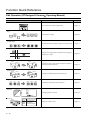
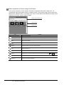
Function Quick Reference
Edit Operation (GT Designer2 Version
Operating Manual)
Image
Function
Page
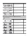
Preview
Show the preview of screen image of GOT.
Page 4-43
Aligns objects or images
Page 8-22
Sets same attributes to objects or images in the same screen
Page 9-1
Align
Property sheet
Guidelines
Displays lines to align figures and objects when arranging a
placed figure or object.
Page 8-25
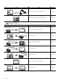
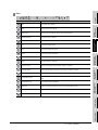
Replace colors
Base 2
Base 2
Base 3
Base 3
Changes the color(s) of the objects and figures arranged on
plural screens at the same time
Page 9-12
Base 1
Base 1
Replace shapes
Base 2
Base 2
Base 3
Base 3
Changes the switch/lamp figures at the same time
Page 9-12
Changes the preset devices at the same time
Page 9-12
Overlapping images or objects
Page 9-16
Display the set device in list
Page 9-17
Base 1
Base 1
Replace devices
M10
M11
M12
M100
M101
M102
Data View
Select
Device list
Base 2
Base 3
Base 1
A - 10
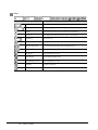
D100
Numerical display
D200
ASCII display
D300
Panel meter display
Image
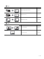
Text list
Base 2
Function
Page
Base 3
Run
Stop
Error
Bit Switch
Bit Switch
Word Lamp
Displays the direct input texts in a list.
Page 9-19
Input characters or comments in other language.
Page 9-26
Imports BMP/DXF files
Page 8-13
Utilizes other project data
Page 9-35
Base 1
Multiple language input
Man.
Auto
English
Chinese
Import BMP/DXF file
BMP file
Import
DXF file
Import Project
Import
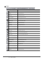
Object Functions (GT Designer2 Version
Reference Manual)
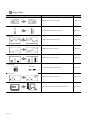
1 Lamp, Touch Switch
Image
Function
Page
Lamp
Red
Blue
RUN
STOP
Displays device value via lamp color changing
Page 6-1
Touch it to switch device ON/OFF
Page 6-19
Touch it to change bit device value
Page 6-36
Touch it to switch to the extended function screen
Page 6-41
Touchitto switch between the base and window screen
Page 6-49
Bit Switch
MO : ON
OFF
D100 :
200
350
Data Set Switch
Special Function Switch
MOV
MOV
MOV
MOV
MOV
K
1
K
2
D1
D2
RST V
K
90 D162
K
110 D167
K
100 D172
GO TO Screen Switch
Operation
Stop
Base 1
Base 2
A - 11
Image
Function
Page
Change Station Switch
Change monitor
destination
Touch it to switch the monitored PLC station No.
Page 6-59
Used as the key for inputting numerical value/ASCII
Page 6-65
Key Code Switch
A
A B C D
E F G H
2 Digit/Font Display
Image
Function
Page
Numerical Display
334
D100
D100 : 334
Displays device value in numerical value
Page 7-1
Write value on device
Page 7-1
Display multipledevice value in list
Page 7-28
Displays device value in text
Page 7-44
Inputs text code device
Page 7-44
Displays hour/minutes, year/month/date
Page 7-57
Displays command
Page 7-63
Numerical Input
45
D100
D100 : 45
Data List
D100 : 55
D101 : 122
D102 : 34
D100
55
D101
122
D102
34
ASCII Display
D10 : 4241H(BA)
D11 : 4443H(DC)
ABCD
ASCII Input
D10 : 4241H(BA)
D11 : 4443H(DC)
ABCD
Clock Display
02/03/18
15:27
Comment Display
RUN
A - 12
STOP
3 Alarm
Image
Function
Page
Alarm List
02/04/18 13:25:40
RUN STOP
Displays message at alarm occurence
Page 8-1
Displays alarm history
Page 8-31
Displays alarm in floating
Page 8-67
Alarm History
Time message
13:25 RUN A STOP
13:05 Hight limit over
13:03 Motor trip
Floating Alarm
Alarm
Alarm occur
4 Parts
Image
Function
Page
Parts Display
Part1
Display entered device
Page 9-1
Displays moving parts
Page 9-28
Part2
Parts Movement
A - 13
5 Graph, Meter
Image
Function
Page
Panel meter
Displays device data on panel meter
Page 10-1
Displays device data in proportional level
Page 10-14
Displays device data in trend graph
Page 10-28
Displays device data in line graph
Page 10-44
Displays device data in bar graph
Page 10-59
Displays device data in statistics graph
Page 10-71
Displays device data in scatter grap
Page 10-81
Collect the device value and edit collected data on PC
Page 10-102
Level
Trend Graph
Line Graph
Bar Graph
Statistics Graph
Pie Graph
Bar Graph
Scatter Graph
Sampling
A - 14
6 Trigger
action
Image
Function
Page
Status observation function
Monitors status of device and write value to device or
Write
D100 : 0
150
operates GOT when condition meets
Page 11-1
Recipe functioin
Write
/Read
D100 : 150
D101 : 300
D102 : 208
Monitors status of device and write/read device data when
condition meets
Page 11-12
Time action function
Outputs the device writing and sound at specified time.
Page 11-22
7 External input/output
Image
Function
Page
Report
Collects numerical data when condition meets and prints the
numerical data and corresponding code.
Page 12-1
Hardcopy
Outputs the GOT monitor screen to printer or memory card
Page 12-25
Uses operation panel to execute device writing
Page 12-31
Writes data read by barcode reader to device
Page 12-39
Outputs sounds
Page 12-46
Displays video
Page 12-50
Operation panel
X0
Bar code
1350
Sound
Video
A - 15
Image
Function
Page
RGB display
Displays PC screens
Page 12-68
8 Others
Image
Set overlay screen
Function
Page
Menu
Base 1
Menu
Base 3
Set overlay screen from other screens
Page 13-1
Changes device value via test window in monitor screen
Page 13-10
Menu
Base 2
Test
9 Script function
Image
Script
Function
if(([b:X1]==OFF)&&([b:X2]==OFF)&&([b:X3]==OFF))
{[w:D10]=1;}
if(([b:X1]==ON)&&([b:X2]==OFF)&&([b:X3]==OFF))
{[w:D10]=2;}
if(([b:X1]==OFF)&&([b:X2]==ON)&&([b:X3]==OFF))
{[w:D10]=3;}
if(([b:X1]==OFF)&&([b:X2]==OFF)&&([b:X3]==ON))
{[w:D10]=4;}
Controls GOT display by scripts
Page
Page 14-1
10 Object setting
Image
Function
Page
Data operation
D100 :
45
D100
180
Offset
180
Operates device values by expression and enables objects
using the operated value
Page 5-45
Numerical value input: D100
200
Accumulates the offset device value in monitor device address
Write to D110
10
and monitor
Page 5-52
Offset device: D200
Security
*****
A - 16
Restricts the password users
Page 5-56
Data Transmission (GT Designer2 Version
Image
Operating Manual)
Function
Page
Download
Transimits monitor screen data from PC to GOT
Page 5-1
Transmits monitor screen data from GOT to PC
Page 5-20
Upload
Print (GT Designer2 Version
Image
Operating Manual)
Function
Page
Print screen
Print base/window/report screen
Page 6-1
A - 17
Manuals
Relevant Manual
For relevant manual, refer to the PDF manual stored within the drawing software.
A - 18
ABBREVIATIONS AND GENERIC TERMS
Abbreviations and generic terms used in this manual are as follows:
GOT
Abbreviations and generic terms
GT SoftGOT1000
Abbreviation of GT SoftGOT1000
GT1595
GT1595-X
Abbreviation of GT1595-XTBA, GT1595-XTBD
GT1585V-S
Abbreviation of GT1585V-STBA, GT1585V-STBD
GT1585-S
Abbreviation of GT1585-STBA, GT1585-STBD
GT1585
GT157
GT156
GOT1000 Series
Description
GT155
GT15
GT115
GT1575V-S
Abbreviation of GT1575V-STBA, GT1575V-STBD
GT1575-S
Abbreviation of GT1575-STBA, GT1575-STBD
GT1575-V
Abbreviation of GT1575-VTBA, GT1575-VTBD
GT1575-VN
Abbreviation of GT1575-VNBA, GT1575-VNBD
GT1572-VN
Abbreviation of GT1572-VNBA, GT1572-VNBD
GT1565-V
Abbreviation of GT1565-VTBA, GT1565-VTBD
GT1562-VN
Abbreviation of GT1562-VNBA, GT1562-VNBD
GT1555-V
Abbreviation of GT1555-VTBD
GT1555-Q
Abbreviation of GT1555-QTBD, GT1555-QSBD
GT1550-Q
Abbreviation of GT1550-QLBD
, GT15
GT1155-Q
Abbreviation of GT1595, GT1585, GT157 , GT156 , GT155
Abbreviation of GT1155-QTBDQ, GT1155-QSBDQ, GT1155-QTBDA, GT1155-QSBDA,
GT1155-QTBD, GT1155-QSBD
GT1150-Q
Abbreviation of GT1150-QLBDQ, GT1150-QLBDA, GT1150-QLBD
Handy
GT1155HS-Q
Abbreviation of GT1155HS-QSBD
GOT
GT1150HS-Q
Abbreviation of GT1150HS-QLBD
GT11
, GT11
GT1030
Abbreviation of GT1030-LBD, GT1030-LBD2, GT1030-LBDW, GT1030-LBDW2
Abbreviation of GT1020-LBD, GT1020-LBD2, GT1020-LBL, GT1020-LBDW,
GT1020
GT10
Abbreviation of GT1155-Q, GT1150-Q, GT11 Handy GOT
GT1020-LBDW2, GT1020-LBLW
, GT10
Abbreviation of GT1030, GT1020
GOT900 Series
Abbreviation of GOT-A900 series, GOT-F900 series
GOT800 Series
Abbreviation of GOT-800 series
Communication unit
Abbreviations and generic terms
Description
GT15-QBUS,
GT15-QBUS2,
GT15-ABUS,
GT15-ABUS2,
GT15-75QBUSL,
GT15-75QBUS2L,
GT15-75ABUSL,
GT15-75ABUS2L
Serial communication unit
GT15-RS2-9P,
GT15-RS4-9S,
GT15-RS4-TE
RS-422 conversion unit
GT15-RS2T4-9P,
GT15-RS2T4-25P
Ethernet communication unit
GT15-J71E71-100
MELSECNET/H communication unit
GT15-J71LP23-25,
GT15-J71BR13
MELSECNET/10 communication unit
GT15-75J71LP23-Z*1,
GT15-75J71BR13-Z*2
Bus connection unit
CC-Link IE controller network communication
unit
GT15-J71GP23-SX
CC-Link communication unit
GT15-J61BT13,
Interface converter unit
GT15-75IF900
*1
GT15-75J61BT13-Z*3
A9GT-QJ71LP23 + GT15-75IF900 set
*2
A9GT-QJ71BR13 + GT15-75IF900 set
*3
A8GT-J61BT13 + GT15-75IF900 set
A - 19
Option unit
Abbreviations and generic terms
Printer unit
Video/RGB unit
Description
GT15-PRN
Video input unit
GT15V-75V4
RGB input unit
GT15V-75R1
Video/RGB input unit
GT15V-75V4R1
RGB output unit
GT15V-75ROUT
CF card unit
GT15-CFCD
CF card extension unit*1
GT15-CFEX-C08SET
External I/O unit
GT15-DIO
Sound output unit
GT15-SOUT
*1
GT15-CFEX + GT15-CFEXIF + GT15-C08CF set.
Option
Abbreviations and generic terms
Memory card
CF card
Memory card adaptor
Option function board
Battery
Protective Sheet
Description
GT05-MEM-16MC,
GT05-MEM-32MC,
GT05-MEM-128MC,
GT05-MEM-256MC
GT05-MEM-64MC,
GT05-MEM-ADPC
GT15-FNB,
GT15-QFNB,
GT15-QFNB16M,
GT15-QFNB48M,
GT15-MESB48M,
GT11-50FNB
GT15-QFNB32M,
GT15-BAT,
GT11-50BAT
GT15-90PSCB,
GT15-90PSGB,
GT15-90PSCW,
GT15-90PSGW,
GT15-80PSCB,
GT15-80PSGB,
GT15-80PSCW,
GT15-80PSGW,
GT15-70PSCB,
GT15-70PSGB,
GT15-70PSCW,
GT15-70PSGW,
GT15-60PSCB,
GT15-60PSGB,
GT15-60PSCW,
GT15-60PSGW,
GT15-50PSCB,
GT15-50PSGB,
GT15-50PSCW,
GT15-50PSGW,
GT11-50PSCB,
GT11-50PSGB,
GT11-50PSCW,
GT11-50PSGW,
GT10-30PSCB,
GT10-30PSGB,
GT10-30PSCW,
GT10-30PSGW,
GT10-20PSCB,
GT10-20PSGB,
GT10-20PSCW,
GT10-20PSGW
GT05-90PCO,
GT05-80PCO,
GT05-70PCO,
GT05-60PCO,
GT11H-50PSC,
Protective cover for oil
USB environmental protection cover
GT05-50PCO
GT15-UCOV,
GT11-50UCOV
GT15-90STAND,
GT15-80STAND,
GT15-70STAND,
A9GT-50STAND,
GT15-70ATT-98,
GT15-70ATT-87,
GT15-60ATT-97,
GT15-60ATT-96,
GT15-60ATT-87,
GT15-60ATT-77,
GT15-50ATT-95W,
GT15-50ATT-85
GT15-90XLTT,
GT15-80SLTT,
GT15-70SLTT,
GT15-70VLTT,
GT15-70VLTN,
GT15-60VLTT,
GT15-60VLTN
Multi-color display board
GT15-XHNB,
GT15-VHNB
Connector conversion box
GT11H-CNB-37S
Emergency stop sw guard cover
GT11H-50ESCOV
Memory loader
GT10-LDR
Stand
Attachment
Backlight
A - 20
GT05-50STAND
Software
Abbreviations and generic terms
Description
GT Works2 Version
SW D5C-GTWK2-E, SW D5C-GTWK2-EV
GT Designer2 Version
SW D5C-GTD2-E, SW D5C-GTD2-EV
GT Designer2
Abbreviation of screen drawing software GT Designer2 for GOT1000/GOT900 series
GT Converter2
Abbreviation of data conversion software GT Converter2 for GOT1000/GOT900 series
GT Simulator2
Abbreviation of screen simulator GT Simulator 2 for GOT1000 / GOT900 series
GT SoftGOT1000
Abbreviation of monitoring software GT SoftGOT1000
GT SoftGOT2
Abbreviation of monitoring software GT SoftGOT2
GX Developer
Abbreviation of SW D5C-GPPW-E(-EV)/SW D5F-GPPW-E type software package
GX Simulator
Abbreviation of SW D5C-LLT-E(-EV) type ladder logic test tool function software packages
(SW5D5C-LLT (-EV) or later versions)
Document Converter
Abbreviation of document data conversion software Document Converter for GOT1000 series
PX Developer
Abbreviation of SW D5C-FBDQ-E type FBD software package for process control
License key (for GT SoftGOT1000)
Abbreviations and generic terms
License
Description
GT15-SGTKEY-U, GT15-SGTKEY-P
License key (for GT SoftGOT2)
Abbreviations and generic terms
Description
License key
A9GTSOFT-LKEY-P (For DOS/V PC)
License key FD
SW5D5F-SGLKEY-J (For PC CPU module)
A - 21
Others
Abbreviations and generic terms
Description
OMRON PLC
Abbreviation of PLC manufactured by OMRON Corporation
KEYENCE PLC
Abbreviation of PLC manufactured by KEYENCE CORPORATION
KOYO EI PLC
Abbreviation of PLC manufactured by KOYO ELECTRONICS INDUSTRIES CO., LTD.
SHARP PLC
Abbreviation of PLC manufactured by Sharp Corporation
JTEKT PLC
Abbreviation of PLC manufactured by JTEKT Corporation
TOSHIBA PLC
Abbreviation of PLC manufactured by TOSHIBA CORPORATION
TOSHIBA MACHINE PLC
Abbreviation of PLC manufactured by TOSHIBA MACHINE CO., LTD.
HITACHI IES PLC
Abbreviation of PLC manufactured by Hitachi Industrial Equipment Systems Co., Ltd.
HITACHI PLC
Abbreviation of PLC manufactured by Hitachi, Ltd.
FUJI FA PLC
Abbreviation of PLC manufactured by Fuji Electric FA Components & Systems Co., Ltd.
MATSUSHITA PLC
Abbreviation of PLC manufactured by Matsushita Electric Works, Ltd.
YASKAWA PLC
Abbreviation of PLC manufactured by YASKAWA Electric Corporation
YOKOGAWA PLC
Abbreviation of PLC manufactured by Yokogawa Electric Corporation
ALLEN-BRADLEY PLC
Abbreviation of Allen-Bradley PLC manufactured by Rockwell Automation, Inc.
GE FANUC PLC
Abbreviation of PLC manufactured by GE Fanuc Automation Corporation
SCHNEIDER PLC
Abbreviation of PLC manufactured by Schneider Electric SA
SIEMENS PLC
Abbreviation of PLC manufactured by Siemens AG
OMRON temperature
controller
SHINKO indicating
controller
CHINO controller
Temperature
controller
FUJI SYS temperature
controller
YAMATAKE temperature
controller
YOKOGAWA temperature
controller
RKC temperature
controller
Abbreviation of temperature controller manufactured by OMRON Corporation
Abbreviation of temperature controller manufactured by Shinko Technos Co., Ltd.
Abbreviation of temperature controller manufactured by CHINO CORPORATION
Abbreviation of temperature controller manufactured by Fuji Electric Systems Co., Ltd.
Abbreviation of temperature controller manufactured by Yamatake Corporation
Abbreviation of temperature controller manufactured by Yokogawa Electric Corporation
Abbreviation of temperature controller manufactured by RKC INSTRUMENT INC.
PC CPU module
Abbreviation of PC CPU Unit manufactured by CONTEC CO., LTD
GOT (server)
Abbreviation of GOTs that use the server function
GOT (client)
Abbreviation of GOTs that use the client function
Windows
font
Intelligent function module
MODBUS
A - 22
/TCP
Abbreviation of TrueType font and OpenType font available for Windows
(Differs from the True Type fonts settable with GT Designer2)
Indicates the modules other than the PLC CPU, power supply module and I/O module that are
mounted to the base unit.
Generic term for the protocol designed to use MODBUS
network.
protocol messages on a TCP/IP
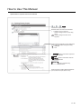
How to Use This Manual
Specification of symbols used in this manual
Indicates the operation steps.
Brackets used for the menu and items differ.
[ ] : Refers to menu in menu bar.
Refers to dialog box item or GOT utility
menu.
: Refers to dialog box buttons or PC
keyboard.
Shows functions applicable to GOT-A900 series
(GOT-A900) GOT-F900 series (GOT-F900).
" " , Applicable
" ",N/A
Point
Refers to information required for
operation.
Refers to information useful for
operation.
Remark Refers to supplementary
explanations.
Shows the items including detailed explanation
(manual and the chapter, section, item).
A - 23
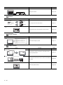
Product List
The following shows the product list of GT Works2 or GT Designer2.
End-user software
license agreement
SW1D5C-GTWK2-E
or
Software
registration form
About installation method of GT
End-user software
Software
Works2/GT Designer2
license agreement
registration form
SW1D5C-GTD2-E
License agreement
License agreement
NOTICES
We don't guarantee the commercially-available Microsoft Windows Operating
System-based software products that have been introduced in this manual.
We hold the copyrights of this software package.
No part of this manual may be transcribed or duplicated in any form without
prior permission by Mitsubishi Electric Corporation.
We have attempted to cover all the revisions of software and hardware, but this
manual may not contain the latest revisions.
The software of this product requires one license to be purchased per
computer.
We permit the user to use this software package (including this manual) based
on the Software License Agreement.
We are not liable for consequences or influences due to this software package
(including this manual).
The specifications of this software package and the descriptions in this manual
may be altered in future without prior notice.
A - 24
1
OVERVIEW
1. OVERVIEW
This manual explains the GT Designer2 system configuration, GT Designer2 screen configuration, basic
dialog box operation, creation of new project, data transfer to GOT and convenient operation for screen
editing.
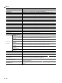
1 Manuals
Three types of manuals are available for GT Designer2.
Refer to the appropriate manual depenfding on the purpose.
The manuals below are stored in PDF files and included with the product.
Draw figures
Make common settings
Arrange/set objects
Transfer data to the GOT
SCREEN CONFIGURATION
OF GT DESIGNER 2
4
CREATING AND
EDITING SCREEN
Operating Manual
Details
Overview
Details
Overview
Details
Overview
Details
Overview
Details
Overview
Details
Overview
5
DATA TRANSFER
OPERATION
Create screens
Reference Manual
6
PRINTING PROJECT/
FILE OUTPUT
Create a project
Manual
7
USING LIBRARY
Install the product into the personal computer
Startup • Introductory
3
Details
8
DRAW AND EDIT
Purpose
2
SYSTEM
CONFIGURATION
1.1 Overview
1.1 Overview
1-1
(1) Startup & Introductory manual
The product installation method is described.
Examples of simple screen creation and operation on the GOT are described.
(2) Reference Manual
Object/figure/screen specifications and object setting methods are described.
(3) Operating Manual
Screen configuration, screen customizing, and procedures from project creation to data transfer on
the GT Designer2 are described.
1-2
1.1 Overview
1
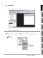
1.2 Feature
OVERVIEW
The GT Designer2 has various functions to improve the drawing efficiency.
Main functions of the GT Designer2 are described below:
SYSTEM
CONFIGURATION
2
SCREEN CONFIGURATION
OF GT DESIGNER 2
3
CREATING AND
EDITING SCREEN
4
Easy-to-use operations
Section 3.1.2 Operation of workspace)
Settings of the overall project such as created screens or common settings are displayed on the tree.
It is convenient to know the current settings, to check progress of work and to copy the screen.
DATA TRANSFER
OPERATION
1 Easy to know the overall project (
5
PRINTING PROJECT/
FILE OUTPUT
6
USING LIBRARY
7
A screen can be newly
created, copied or deleted.
8
DRAW AND EDIT
1.2.1
1.2 Feature
1.2.1 Easy-to-use operations
1-3
Section 9.1.2 Batch setting and
2 Easy to manage objects for each application (
managing objects/figures for each purpose (Category workspace))
The overall project settings are displayed on the tree by category (type).
Classification for each application allows simple management of objects.
Managed for each application.
3 Easy to select parts frequently used (
Chapter 7 USING LIBRARY)
Objects or figures can be registered and pasted on the screen.
Objects or figures frequently used may be registered as buttons on the toolbar.
Pasting
Pasting from toolbar
Simple edit of parts
Part objects or figures once registered can be re-edited with the dedicated editor (library editor).
Double click
Edit with dedicated editor
1-4
1.2 Feature
1.2.1 Easy-to-use operations
1
Useful functions
1 Shortest setting without opening dialog box (
Section 9.1.1 Batch setting of
multiple objects/figures on the same screen (Property sheet))
2
SYSTEM
CONFIGURATION
All setting items and setting details being currently selected are displayed in a list.
Objects and figures can be set without opening the dialog box and the setting details can be checked.
OVERVIEW
1.2.2
SCREEN CONFIGURATION
OF GT DESIGNER 2
3
Setting without opening
dialog box
2 Classifying objects for each application
Since the touch switches are classified for each application, the desired touch switch for setting can be
simply selected. The lamp display function and the part display function are classified into the bit device
and the word device. In this way, the number of setting items is reduced.
CREATING AND
EDITING SCREEN
4
DATA TRANSFER
OPERATION
5
The screen can be customized for the workspace, movement of property sheet or toolbars display/nondisplay. You may create figures in the preferred environment.
The dialog box for setting objects may also be customized.
GT Designer2
Dialog box for object setting
6
PRINTING PROJECT/
FILE OUTPUT
Section 3.4.1 Customizing screen configuration)
7
Movement and display/non-display
of toolbar is available.
Display/non-display for each icon
is also allowed.
Only checked items
are set.
USING LIBRARY
3 Customizing screen (
DRAW AND EDIT
8
Workspace or property
sheet can be moved.
1.2 Feature
1.2.2 Useful functions
1-5
4 Quick selection of desired screen for editing (
Section 4.6.1 Opening screen)
Double click the screen in the project workspace to display the desired screen for editing.
The screen can be displayed
by double clicking the screen
in the workspace.
5 Quick selection of desired part for editing (
overlapped figure (Data view))
Section 9.1.4 Simple selection of
Objects or figures set on the screen can be displayed in a list.
If multiple objects or figures are overlapped, it can be simply selected from the Data View.
Currently selected objects or figures can also be checked.
6 Real time check of settings in graphic display (view direct)
Setting on the property sheet or the dialog box is quickly displayed on the screen.
Since the screen display can be checked, a screen as you wish can be smoothly created.
Quickly displayed
1-6
1.2 Feature
1.2.2 Useful functions
Quickly displayed
1
Section 4.10 Viewing
OVERVIEW
7 Confirming the screen display on the GOT (Preview) (
Created Screen Image)
The screen display on the GOT can be confirmed on GT Designer2.
Also, the windowed screen can be confirmed.
SYSTEM
CONFIGURATION
2
SCREEN CONFIGURATION
OF GT DESIGNER 2
3
Base Screen Preview
CREATING AND
EDITING SCREEN
4
Windowed Screen Preview
DATA TRANSFER
OPERATION
5
PRINTING PROJECT/
FILE OUTPUT
6
USING LIBRARY
7
DRAW AND EDIT
8
1.2 Feature
1.2.2 Useful functions
1-7
2. SYSTEM CONFIGURATION
2.1 System Configuration in Creating Monitor Screen
2.1.1
System configuration
The system configuration of GT Designer2 is shown below:
GT Designer2 Version
PC
2.1.2
Operating environment
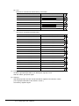
The operating environment of GT Designer2 is shown below:
Item
Description
Personal computer
PC/AT compatible personal computer that Windows® runs on
Operating system
Microsoft® Windows® 98 Operating System
(English, Simplified Chinese, Traditional Chinese, Korean, German versions)
Microsoft® Windows® Millennium Edition Operating System
(English, Simplified Chinese, Traditional Chinese, Korean, German versions)
Microsoft® Windows NT® Workstation 4.0 Operating System Service Pack 3 or later
(English, Simplified Chinese, Traditional Chinese, Korean, German versions)*1
Microsoft® Windows® 2000 Professional Operating System Service Pack 4 or later
(English, Simplified Chinese, Traditional Chinese, Korean, German versions)*1
Microsoft® Windows® XP Professional Operating System Service Pack 2 or later
(English, Simplified Chinese, Traditional Chinese, Korean, German versions)*2 *4 *5
Microsoft® Windows® XP Home Edition Operating System Service Pack 2 or later
(English, Simplified Chinese, Traditional Chinese, Korean, German versions)*2 *4 *5
Microsoft® Windows Vista® Ultimate Operating System
(English, Simplified Chinese, Traditional Chinese, Korean, German versions)*3 *4 *5
Microsoft® Windows Vista® Enterprise Operating System
(English, Simplified Chinese, Traditional Chinese, Korean, German versions)*3 *4 *5
Microsoft® Windows Vista® Business Operating System
(English, Simplified Chinese, Traditional Chinese, Korean, German versions)*3 *4 *5
Microsoft® Windows Vista® Home Premium Operating System
(English, Simplified Chinese, Traditional Chinese, Korean, German versions)*3 *4 *5
Microsoft® Windows Vista® Home Basic Operating System
(English, Simplified Chinese, Traditional Chinese, Korean, German versions)*3 *4 *5
Computer
CPU
Refer to "Applicable operating system and performance required for personal computer" on the next page.
Memory
Hard disk space
For installation: 1.1GB or more*7
For execution: 100MB or more
Disk drive
CD-ROM drive
Display color
High Color (16 bits) or more
Display*6
Resolution 800
2-1
600 dots or more
2.1 System Configuration in Creating Monitor Screen
2.1.1 System configuration
Item
1
Description
Internet Explorer 5.0 or later must be installed.
Others
Administrator authority is required for installing GT Designer2.
*2:
Administrator authority is required for installing and using GT Designer2.
*3:
Administrator authority is required for installing GT Designer2.
OVERVIEW
The mouse, keyboard, printer, and CD-ROM drive must be compatible with the above OS.
*1:
A standard user or Administrator account is required for using GT Designer2.
For interactions between GT Designer2 and the other MELSOFT applications, use GT Designer2 under Administrator authority when the other applications are used under Administrator authority.
*5:
The following functions are not supported.
• "Compatibility mode"
• "Fast user switching"
• "Change your desktop themes (fonts)"
• "Remote desktop"
Only the 32-bit OS is available.
*6:
For using the MES interface function, a display resolution of 1024
*7:
800MB or more when using Windows® 98, Windows® Millennium Edition or Windows NT®.
768 dots or more is required.
3
SCREEN CONFIGURATION
OF GT DESIGNER 2
Applicable operating system and performance required for personal computer
Performance required for personal computer
Pentium® 200MHz or more
64MB or more
Microsoft® Windows® Millennium Edition Operating System
(English, Simplified Chinese, Traditional Chinese, Korean, German
versions)
Pentium® 200MHz or more
64MB or more
Microsoft® Windows NT® Workstation 4.0 Operating System Service Pack3
or later
(English, Simplified Chinese, Traditional Chinese, Korean, German
versions)
Pentium® 200MHz or more
64MB or more
Microsoft® Windows® 2000 Professional Operating System Service Pack4
or later
(English, Simplified Chinese, Traditional Chinese, Korean, German
versions)
Pentium® 200MHz or more
64MB or more
Pentium II® 300MHz or more
128MB or more
Microsoft® Windows® XP Professional Operating System Service Pack2 or
later
(English, Simplified Chinese, Traditional Chinese, Korean, German
versions)
Microsoft® Windows® XP Home Edition Operating System Service Pack2 or
later
(English, Simplified Chinese, Traditional Chinese, Korean, German
versions)
4
CREATING AND
EDITING SCREEN
Memory
5
DATA TRANSFER
OPERATION
CPU
Microsoft® Windows® 98 Operating System
(English, Simplified Chinese, Traditional Chinese, Korean, German
versions)
6
PRINTING PROJECT/
FILE OUTPUT
Operating system
Microsoft® Windows Vista® Ultimate Operating System
(English, Simplified Chinese, Traditional Chinese, Korean, German
versions)
Microsoft® Windows Vista® Business Operating System
(English, Simplified Chinese, Traditional Chinese, Korean, German
versions)
Microsoft® Windows Vista® Home Premium Operating System
(English, Simplified Chinese, Traditional Chinese, Korean, German
versions)
800MHz or more
512MB or more
(Recommended: 1GHz or
(Recommended: 1GB or
more)
more)
7
USING LIBRARY
Microsoft® Windows Vista® Enterprise Operating System
(English, Simplified Chinese, Traditional Chinese, Korean, German
versions)
2
SYSTEM
CONFIGURATION
*4:
Microsoft® Windows Vista® Home Basic Operating System
(English, Simplified Chinese, Traditional Chinese, Korean, German
versions)
DRAW AND EDIT
8
2.1 System Configuration in Creating Monitor Screen
2.1.2 Operating environment
2-2
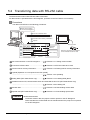
2.2 System Configuration of Data Transfer and
Document Creation
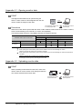
2.2.1
System configuration
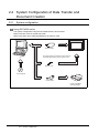
1 Using GOT-A900 series
The system configuration using the GOT-A900 series is shown below.
Refer to Section 2.2.2 for the RS-232 cable.
Refer to the GOT user's manual (Details) for the memory card.
POWER
RS-232 cable
GOT-A900 series
PC
The OS program and monitor screen data can
be transferred (written) to the memory card.
Memory card
GT Designer2
Printer cable
Printer compatible
with Windows R
2-3
2.2 System Configuration of Data Transfer and Document Creation
2.2.1 System configuration
1
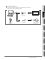
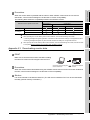
2 Using GOT-F900 series
OVERVIEW
The system configuration using the GOT-F900 series is shown below.
Refer to Section 2.2.2 for the RS-232 cable.
RS-232 cable
SYSTEM
CONFIGURATION
2
GOT-F900 series
PC
Printer cable
Printer compatible
R
with W indows
CREATING AND
EDITING SCREEN
4
DATA TRANSFER
OPERATION
5
PRINTING PROJECT/
FILE OUTPUT
6
USING LIBRARY
7
8
DRAW AND EDIT
GT Designer2
SCREEN CONFIGURATION
OF GT DESIGNER 2
3
2.2 System Configuration of Data Transfer and Document Creation
2.2.1 System configuration
2-4
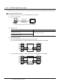
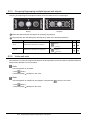
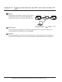
2.2.2
RS-232 cable to be used
The cable type for connection between the PC and the GOT and the connection diagram are shown below.
1 Using GOT-A900 series
The cable shown below or in the connection diagram is required.
(1) System configuration
AC30R2-9SS
FX-232CAB-1
AC30R2-9P 1
F2-232CAB-1 1
PC
*1
GOT
9-25 pin converter (Diatrend Corp. D232J31) is required.
(2) Cable for use
Cable
Manufacturer
AC30R2-9SS (9 pin - 9 pin)
FX-232CAB-1 (9 pin - 9 pin)
Mitsubishi Electric Corporation
AC30R2-9P (9 pin - 25 pin)
F2-232CAB-1 (9 pin - 25 pin)
(3) Connection diagram
Use the screw-in type (inch screw) connector for the GOT.
(a) Connection diagram for cables equivalent to AC30R2-9SS and FX-232CAB-1
RXD
TXD
RTS
CTS
DSR
SG
DTR
PC
2
3
7
8
6
5
4
GOT
2
3
7
8
6
5
4
RXD
TXD
RTS
CTS
DSR
SG
DTR
Shield
(b) Connection diagram for cables equivalent to AC30R2-9P and F2-232CAB-1
TXD
RXD
RTS
CTS
DSR
SG
DTR
PC
2
3
4
5
6
7
20
GOT
2
3
7
8
6
5
4
Shield
2-5
2.2 System Configuration of Data Transfer and Document Creation
2.2.2 RS-232 cable to be used
RXD
TXD
RTS
CTS
DSR
SG
DTR
1
2 Using GOT-F900 series
OVERVIEW
The cable shown below or in the connection diagram is required.
(1) System configuration
FX-232CAB-1
F2-232CAB-1
SYSTEM
CONFIGURATION
2
GOT
(2) Cable for use
Cable
Manufacturer
3
SCREEN CONFIGURATION
OF GT DESIGNER 2
Mitsubishi Electric Corporation
(3) Connection diagram
Use the screw-in type (inch screw) connector for the GOT.
(a) Connection diagram for cables equivalent to FX-232CAB-1.
GOT
2
3
7
8
6
5
4
PC
2
3
7
8
6
5
4
4
RXD
TXD
RTS
CTS
DSR
SG
DTR
CREATING AND
EDITING SCREEN
RXD
TXD
RTS
CTS
DSR
SG
DTR
Shield
5
TXD
RXD
RTS
CTS
DSR
SG
DTR
GOT
2
3
7
8
6
5
4
PC
2
3
4
5
6
7
20
DATA TRANSFER
OPERATION
(b) Connection diagram for cables equivalent to F2-232CAB-1.
RXD
TXD
RTS
CTS
DSR
SG
DTR
6
Shield
(1) Cable to be used
The cable for the Version A or later cannot be used.
The RS-232 cable for the Version A or later has the version name at the upper
right of the model on the connector. Check the version.
AC30R2-9SS
A
(2) Cable to be created
Use the F2-232CAB-1 connection cable when the PLC CPU and the GOT are
used at the same time with FX-2PIF by connecting the F940GOT or the F930GOT
to the A series CPU or the FX series CPU through the RS-422 cable.
2.2 System Configuration of Data Transfer and Document Creation
2.2.2 RS-232 cable to be used
2-6
PRINTING PROJECT/
FILE OUTPUT
FX-232CAB-1 (9 pin - 9 pin)
7
USING LIBRARY
AC30R2-9SS (9 pin - 9 pin)
8
DRAW AND EDIT
PC
3. SCREEN CONFIGURATION OF GT
DESIGNER 2
3.1 Screen Configuration and Basic Operation
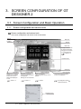
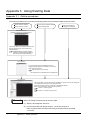
3.1.1
Screen configuration and various tools
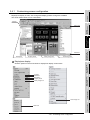
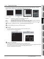
1 Screen configuration and various tools
The screen configuration and various tools are described.
Title bar
Menu bar
Toolbars
Title bar
Data View
All object functions and
its number and figures
arranged on the screen
are displayedin a list.
Section 9.1.5
Created screen
Status bar
Workspace
Settings on the overall
project such as created
screen and common
settings are displayed
in tree.
Section 3.1.2
Property sheet
Attributes of selected
screen, objects and figures
are displayed.
Settings can be made here.
Section 9.1.1
Library Image list
Library is displayed.
Objects/figures in library can be
pasted.
Chapter 7
3.1 Screen Configuration and Basic Operation
3.1.1 Screen configuration and various tools
Parts used in the part display
function are displayed.
GT Designer2 Version
Reference Manual
Dropdown menu
3-1
Part Image list
1
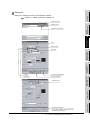
2 Dialog box
OVERVIEW
Refer to the following section for the operation method.
Section 4.7.5 Basic operations of dialog box
Go up one level
2
SYSTEM
CONFIGURATION
Display menu
Creation of new folder
SCREEN CONFIGURATION
OF GT DESIGNER 2
3
Tab
Radio button
4
CREATING AND
EDITING SCREEN
Spin box
DATA TRANSFER
OPERATION
5
Function list check box
Check box
Command button
6
PRINTING PROJECT/
FILE OUTPUT
List box
Extension tab
USING LIBRARY
7
DRAW AND EDIT
8
Function list check box
When this is checked, the extension tab
is additionally displayed.
3.1 Screen Configuration and Basic Operation
3.1.1 Screen configuration and various tools
3-2
Check box
View of table
3-3
3.1 Screen Configuration and Basic Operation
3.1.1 Screen configuration and various tools
1
OVERVIEW
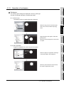
Operation of workspace
1 Workspace
The overall project settings are displayed in a tree by data type.
It is easy to manage and edit the overall project data.
2
SYSTEM
CONFIGURATION
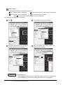
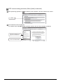
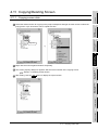
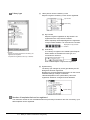
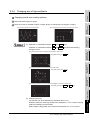
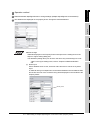
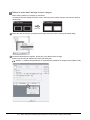
Ex. 1) Screen copy
The existing screen is copied using the workspace.
Select the copy source screen and right
3
SCREEN CONFIGURATION
OF GT DESIGNER 2
click on the mouse to select the [Copy]
menu.
Right click the mouse again to select the
[Paste] menu.
When the screen property is set, the screen
is copied.
CREATING AND
EDITING SCREEN
4
5
DATA TRANSFER
OPERATION
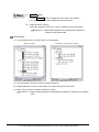
Ex. 2) Part registration
A figure is registered as a part using the workspace.
Drag
Select the figure for registration and drag it
6
PRINTING PROJECT/
FILE OUTPUT
to the Parts folder in the workspace.
7
When the part number and name are set,
the figure is registered as a part.
USING LIBRARY
3.1.2
DRAW AND EDIT
8
3.1 Screen Configuration and Basic Operation
3.1.2 Operation of workspace
3-4
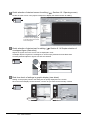
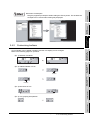
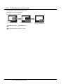
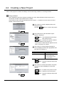
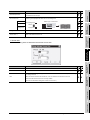
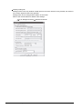
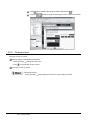
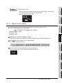
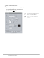
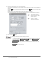
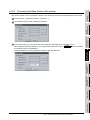
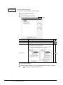
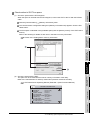
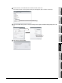
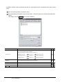
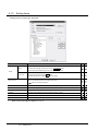
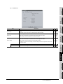
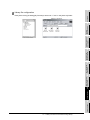
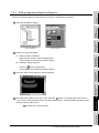
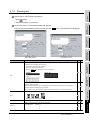
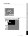
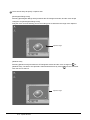
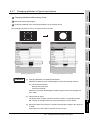
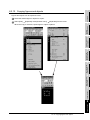
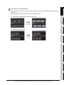
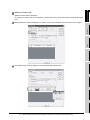
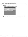
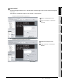
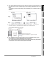
2 Basic operations of Screen Image List Window
In the project workspace, Screen Image List Window is displayed when [Open Image View...] is
selected after right-clicking Base Screen or Window Screen. In the Screen Image List, an image from
Base Screen, Window Screen, or an image of set overlay screen (Base Screen/Window Screen) can be
displayed, and screen can be created or edited.
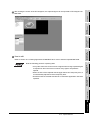
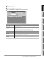
Screen type selection menu
Screen image
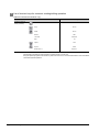
Screen name
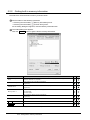
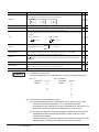
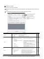
Item
Screen type selection menu
3-5
Contents
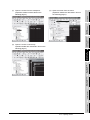
Screen type is switched.
(Register)
Figures and objects that are selected with screen editor are placed on the created screen.
(New)
New screen is created.
(Edit)
Registered screen details are edited with screen editor.
(Name)
Display/non-display of the screen name is selected.
(Cut)
Selected screen is cut.
(Copy)
Selected screen is copied.
(Paste)
Copied screen, cut screen are pasted on the screen with the press of each
(Delete)
Selected screen is deleted.
(Property)
Property of the screen is displayed.
3.1 Screen Configuration and Basic Operation
3.1.2 Operation of workspace
Copy , Cut button.
1
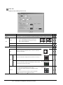
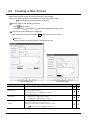
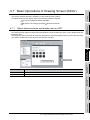
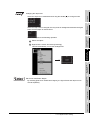
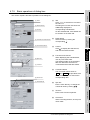
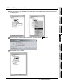
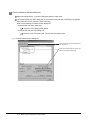
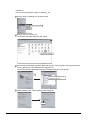
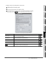
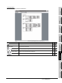
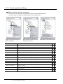
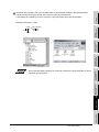
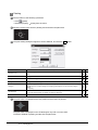
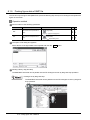
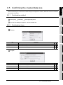
3 Workspace type
OVERVIEW
Types of the workspace are described here.
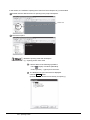
Project workspace
Overall project settings such as created screens and common settings are displayed in a tree.
It is convenient to see the project details, to check the work progress and to copy a screen.
SYSTEM
CONFIGURATION
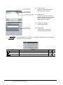
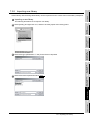
Display Overlay Screen
2
Set overlay screen
status is displayed
in a tree.
When this is checked,
the set overlay screen
status is displayed in
a tree.
SCREEN CONFIGURATION
OF GT DESIGNER 2
3
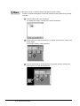
Screen
The created screen is displayed in a tree by type
(base screen, window screen and report screen).
4
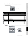
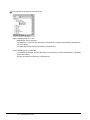
Common Settings
CREATING AND
EDITING SCREEN
The object function settings used in common for the project
are displayed in a tree.
When an item is double clicked, the setting dialog box for
each function is displayed.
DATA TRANSFER
OPERATION
5
Common file
Files of multiple object functions (part, comment and voice)
which are used in common are displayed in a tree.
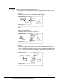
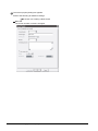
Available functions
Ex.) Drag a figure.
7
USING LIBRARY
Ex.) Right click the window screen.
• Dragging a figure to the Project workspace allows
registration of a Parts.
Drag
8
DRAW AND EDIT
• Right click the mouse to select basic commands
such as New Screen, Open or Copy.
PRINTING PROJECT/
FILE OUTPUT
6
3.1 Screen Configuration and Basic Operation
3.1.2 Operation of workspace
3-6
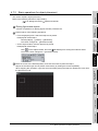
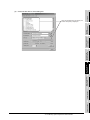
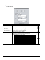
Category workspace
The overall project setting is displayed in a tree by Category (type).
Classification for each application simplifies management and editing of objects.
Section 9.1.2 Batch setting and managing objects/figures for each purpose (Category
workspace)
Library workspace
Objects or figures can be registered and pasted to the screen.
Chapter 7 USING LIBRARY
3-7
3.1 Screen Configuration and Basic Operation
3.1.2 Operation of workspace
1
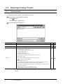
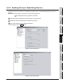
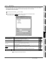
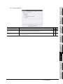
3.2 Menu Configuration
OVERVIEW
Commands assigned to the menu bar are described.
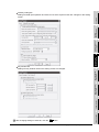
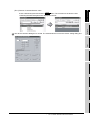
Project
The Project menu contains functions of file management, preference
settings and printing.
New creation of project, reading existing files, preference settings and
printing of data being edited are available.
The recent file record can also be displayed.
SYSTEM
CONFIGURATION
2
The Edit menu contains edit functions for created figures/objects.
If incorrect operation is done during edit, the screen can be returned to
the previous status. Copy, paste and grouping of objects and figures
are also allowed.
Chapter 8 DRAW AND EDIT
4
CREATING AND
EDITING SCREEN
Edit
SCREEN CONFIGURATION
OF GT DESIGNER 2
3
DATA TRANSFER
OPERATION
5
The View menu contains functions of display on the GT Designer2.
Toolbars, status bar, workspace or property sheet can be displayed or
not displayed.
Clause 3.4.1 Customizing screen configuration
6
PRINTING PROJECT/
FILE OUTPUT
View
USING LIBRARY
7
DRAW AND EDIT
8
3.2 Menu Configuration
3-8
Screen
The Screen menu contains functions of screen management and
settings in a project.
New screen creation, opening/closing screen and change of window
size are available.
Chapter 4 CREATING AND EDITING SCREEN
Common
The Common menu contains functions of common settings.
The object functions used for the overall project can be set.
Comment, part and voice, etc. can also be registered.
Refer to the manual below for details of common settings.
GT Designer2 Version
Reference Manual
Figure
The Figure menu contains functions of drawing figures.
Various figures can be drawn or figures can be filled. Image data can
also be imported.
Chapter 8 DRAW AND EDIT
3-9
3.2 Menu Configuration
1
Object
OVERVIEW
The Object menu contains functions of objects such as lamps or
switches witch are arranged on the screen.
Refer to the manual below for details of each object functions.
Reference Manual
2
SYSTEM
CONFIGURATION
GT Designer2 Version
SCREEN CONFIGURATION
OF GT DESIGNER 2
3
Tools
The Tool menu contains functions of list display of set devices and
error check of setting items.
The data view can be displayed or not displayed.
CREATING AND
EDITING SCREEN
4
Chapter 9 USEFUL FUNCTIONS
Communication
The communication menu contains functions of download, upload,
display of GOT memory information and communication settings.
Chapter 5 DATA TRANSFER OPERATION
5
DATA TRANSFER
OPERATION
Window
The Window menu contains functions of tiling multiple screens.
Clause 4.8 Operating Multiple Screens
The Help menu contains functions of viewing the PDF manual related
to the GT Designer2 and checking the software version.
Clause 3.6 How to View the Product Information
* The commands in this chapter is shown for the case of the largest display of the GOT-A900 series. For the GOT-
7
USING LIBRARY
F900 series, there are some differences for each model, and some models do not display all commands.
PRINTING PROJECT/
FILE OUTPUT
6
Help
DRAW AND EDIT
8
3.2 Menu Configuration
3 - 10
3.3 Toolbars
3.3.1
Types of toolbars
The following types of toolbars are available.
When desired toolbars are checked for display/non-display, the toolbars can be displayed/non-displayed
accordingly.
Displays the Main toolbar.
Displays the View toolbar.
Displays the Figure toolbar.
Displays the Object toolbar.
Displays the Edit toolbar.
Displays the Align toolbar.
Displays the Draw toolbar.
Displays the Communication toolbar.
Displays the Report toolbar.
Displays the My Favorites toolbar.
Displays the Comment toolbar.
Displays the Coordinate/Size toolbar.
Displays the Toolbars tab of the Preferences dialog box.
If you drag a displayed toolbar, it may be arranged as a window on the screen.
The following pages also describe details of each toolbar.
3 - 11
3.3 Toolbars
3.3.1 Types of toolbars
1
Description
New project file is created.
Open
Existing project file is opened.
Save Project
Editing project is overwritten and saved on the existing file.
New Base Screen
New base screen is created.
Open Screen
Specified screen is opened.
Cut
Figures and objects are cut.
Copy
Figures and objects are copied.
Paste
Figures and objects are pasted.
Undo
The last operation is cancelled to recover the status before change.
Redo
The last operation is repeated.
Screen Preview
Settings are displayed with the display image on the GOT.
Previous Screen
Screen with the number before the current screen number is opened.
Next Screen
Screen with the number next to the current screen number is opened.
SCREEN CONFIGURATION
OF GT DESIGNER 2
3
CREATING AND
EDITING SCREEN
4
5
Unopened screen is opened with "Previous/Next Screen" in the ascending/descending
order.
6
List of devices used is displayed.
Data View
All figures and objects arranged on the screen are displayed in a list.
Comment
Comment to be displayed with the object function is registered.
Figure And Object
Objection of selection is switched to "Figure and Object."
7
USING LIBRARY
Screen Device List
PRINTING PROJECT/
FILE OUTPUT
UnOpened Screens
SYSTEM
CONFIGURATION
2
New
DATA TRANSFER
OPERATION
Name
OVERVIEW
1 Main
DRAW AND EDIT
8
3.3 Toolbars
3.3.1 Types of toolbars
3 - 12
2 View
Name
3 - 13
Description
Snap
Snap movement of the cursor is set.
Zoom
Screen display magnification rate/shrinkage rate is set.
Zoom In
Screen display can be zoomed in up to 400% in 10% increments.
Zoom Out
Screen display can be zoomed out up to 50% in 10% increments.
Grid Spacing
Grid interval is set.
Grid Color
Grid color is set.
ON Image, OFF Image
Screen is switched to the display of device ON/device OFF.
Device, Object ID
Device (Dev.) and object ID (ID) are displayed for each object.
Screen Color
Screen background color is set.
Screen Pattern
Screen background pattern is set.
Screen Background Color
Screen background color is set.
Workspace
Workspace is displayed.
Property Sheet
Property Sheet is displayed.
3.3 Toolbars
3.3.1 Types of toolbars
1
Description
2
Line is drawn.
Line FreeForm
Continuous line is drawn.
Rectangle
Rectangle is drawn.
Rectangle (Filled)
Filled rectangle is drawn.
Polygon
Polygon is drawn.
Circle
Circle is drawn.
Circle (Filled)
Filled circle is drawn.
Arc
Arc is drawn.
Sector
Sector is drawn.
Scale
Scale is drawn.
Text
Text is input.
Paint
Polygon and closed area are painted with the selected pattern.
Import Image
BMP format file is imported on the editing screen.
Rectangular Range Area
Rectangular range area is captured.
Window Area
Window area is captured.
Import DXF
DXF format file is imported on the editing screen
SYSTEM
CONFIGURATION
Line
SCREEN CONFIGURATION
OF GT DESIGNER 2
3
CREATING AND
EDITING SCREEN
4
DATA TRANSFER
OPERATION
5
6
PRINTING PROJECT/
FILE OUTPUT
Name
OVERVIEW
3 Figure
USING LIBRARY
7
DRAW AND EDIT
8
3.3 Toolbars
3.3.1 Types of toolbars
3 - 14
4 Object
Name
3 - 15
Description
Switch tool bar
Switch function is set.
Bit Lamp
Bit Lamp function is set.
Word Lamp
Word Lamp function is set.
Numerical Display
Numerical Display function is set.
ASCII Display
ASCII Display function is set.
Numerical Input
Numerical Input function is set.
ASCII Input
ASCII Input function is set.
Time Display
Time Display function is set.
Bit Comment
Bit Comment function is set.
Word Comment
Word Comment function is set.
Alarm History
Alarm History function is set.
User Alarm
Alarm List function (User Alarm) is set.
System Alarm
Alarm List function (System Alarm) is set.
Bit Parts Display
Bit Parts Display function is set.
Word Parts Display
Word Parts Display function is set.
Fixed Parts Display
Fixed Parts Display function is set.
Panel meter
Panel meter function is set.
Level
Level function is set.
Trend Graph
Trend Graph function is set.
Line Graph
Line Graph function is set.
Bar Graph
Bar Graph function is set.
3.3 Toolbars
3.3.1 Types of toolbars
1
Description
Selected figures and objects are arranged to front.
Send to Back
Selected figures and objects are arranged to back.
Group
Selected figures and objects are grouped.
Ungroup
Grouping is canceled.
Flip Horizontal
Selected figure is flipped horizontally.
Flip Vertical
Selected figure is flipped vertically.
Rotate Left
Selected figure is rotated 90 degrees to the left.
Rotate Right
Selected figure is rotated 90 degrees to the right.
Edit Vortex
Length of freeform line or polygon line is changed.
Align
Selected figures and objects are aligned.
Selection: Figure
Only figures are selected.
Selection: Object
Only objects are selected.
Selection: Figure and Object
Figures and objects are selected.
Adjust Direct Text Size
Text size of the target object is automatically adjusted with the size of object area.
2
SYSTEM
CONFIGURATION
Bring to Front
SCREEN CONFIGURATION
OF GT DESIGNER 2
3
CREATING AND
EDITING SCREEN
4
5
DATA TRANSFER
OPERATION
Name
OVERVIEW
5 Edit
6 Align
Description
Align Left
Aligned with the selected leftmost figure or object.
Align Center (Horizontally)
Aligned at the center horizontally.
Align Right
Aligned with the selected rightmost figure or object.
Align Top
Aligned with the selected uppermost figure or object.
Align Center (Vertically)
Aligned at the center vertically.
Align Bottom
Aligned with the selected lowermost figure or object.
Align Across
Selected figures and objects are evenly aligned in the horizontal direction.
Align Down
Selected figures and objects are evenly aligned in the vertical direction.
3.3 Toolbars
3.3.1 Types of toolbars
USING LIBRARY
7
8
DRAW AND EDIT
Name
PRINTING PROJECT/
FILE OUTPUT
6
3 - 16
7 Draw
Name
Description
Line Style
Line style is set or changed.
Line Width
Line width is set or changed.
Line Color
Line color is set or changed.
Fill Pattern
Fill pattern is set or changed.
Pattern Fg Color
Fill color is set or changed.
Pattern Bg Color
Fill background color is set or changed.
Text Color
Text color is set or changed.
Text Style
Text style is set or changed.
Text Solid Color
Text solid color is set or changed.
8 Communication
Name
Description
To/From GOT
Data is transferred to GOT.
To memory Card
Data is transferred to memory Card.
Communication Configuration
Communication setting is made
9 Report
Name
3 - 17
Description
Report Line
Report line (Rectangle) is drawn.
Report Text
Report text is input.
Numerical Print
Numerical value for report printing is set.
Bit Comment Print
Comment (Bit) for report printing is set.
Word Comment Print
Comment (Word) for report printing is set.
Report Repeat Header
Header line is set.
Report Repeat Line
Repeat line is set.
Selection Report Line
Only report lines are selected.
3.3 Toolbars
3.3.1 Types of toolbars
1
Reference Manual
Description
New Comment
Adds a new comment line.
Insert Row
Inserts a row in the specified position.
Import
Imports the existing CSV, text or Unicode text file.
Export
Exports a comment list to a CSV, text or Unicode text file.
Attribute
Opens the comment attribute setting dialog.
Search
Opens the character string search dialog.
Jump
Opens the jump dialog.
4
CREATING AND
EDITING SCREEN
Displays/Hides the attribute information.
DATA TRANSFER
OPERATION
5
PRINTING PROJECT/
FILE OUTPUT
6
7
USING LIBRARY
Display/Non-Display
3
8
DRAW AND EDIT
Attribute
2
SYSTEM
CONFIGURATION
Name
SCREEN CONFIGURATION
OF GT DESIGNER 2
GT Designer2 Version
OVERVIEW
10 Comment
3.3 Toolbars
3.3.1 Types of toolbars
3 - 18
3.4 Customizing Screen Configuration and Toolbars
Screen configuration and toolbars can be customized on the GT Designer2 to facilitate operation by users.
Screen configuration and toolbars customizing methods are described in this section.
Unused toolbars are not displayed.
Toolbars are displayed
as a window.
Size change
Workspace or propertysheet is
moved to desired position.
3 - 19
3.4 Customizing Screen Configuration and Toolbars
Only toolbar icons necessary
for operation are displayed.
(Unnecessary icons are
not displayed.)
3.4.1
1
Customizing screen configuration
OVERVIEW
Display/non-display of tools, size change and display position change are available.
The areas shown below can be customized.
Toolbars
2
SYSTEM
CONFIGURATION
Data View
SCREEN CONFIGURATION
OF GT DESIGNER 2
3
Status bar
Workspace
Library Image List
Property sheet
Parts Image List
1 Display/non-display
CREATING AND
EDITING SCREEN
4
5
DATA TRANSFER
OPERATION
Click the options in the menu below to display/non-display various tools.
Toolbars
Status bar
Workspace
Property sheet
PRINTING PROJECT/
FILE OUTPUT
6
Library Image List
USING LIBRARY
7
Parts Image List
DRAW AND EDIT
8
Data View
3.4 Customizing Screen Configuration and Toolbars
3.4.1 Customizing screen configuration
3 - 20
2 Size change
Click the buttons below to change the screen size:
: The selected screen is minimized.
: The selected screen is returned to the original size.
: The selected screen is maximized.
: The selected screen is closed.
Click
to pop up the workspace, property sheet and data view.
(Ex.) Moving or changing size of workspace
1 Click
.
2 The workspace pops up as a window.
3 Change the window size of the workspace.
(Toolbars size cannot be changed.)
4 When it is dragged to the original position, full
display can be recovered.
A display frame appears
by dragging.
Remark
Customized screen
The GT Designer2 memorizes the customized settings of the screen configuration.
At the next start-up, the previously customized status screen is displayed.
3 - 21
3.4 Customizing Screen Configuration and Toolbars
3.4.1 Customizing screen configuration
1
Drag the popped-up workspace while holding the Ctrl key down. This enables the
workspace to be moved without being fully displayed.
OVERVIEW
Movement of workspace
SYSTEM
CONFIGURATION
2
3.4.2
SCREEN CONFIGURATION
OF GT DESIGNER 2
3
Customizing toolbars
4
CREATING AND
EDITING SCREEN
An icon/toolbar can be added or deleted, and the icon display can be changed.
Refer to the following pages for operation.
(Ex. 1) Deletion of toolbars
DATA TRANSFER
OPERATION
5
(Ex. 2) Addition/deletion of icon
Addition
PRINTING PROJECT/
FILE OUTPUT
6
Deletion
(Ex. 3) Movement of icon
USING LIBRARY
7
(Ex. 4) Icon grouping with partition
DRAW AND EDIT
8
3.4 Customizing Screen Configuration and Toolbars
3.4.2 Customizing toolbars
3 - 22
1 Adding or deleting toolbars/icons
Methods of adding or deleting toolbars/icons are shown below:
1 Select [Project]
[Preferences].
2 The preferences dialog box appears.
Add or delete toolbars/icons with the toolbar tab or the command tab.
Toolbars tab
Toolbars are added or deleted.
Item
Description
Toolbars
Check the desired toolbars for addition. To delete it, remove the check.
Show Tool Tips
When the cursor is placed on the icon, check this to display the icon name.
With Shortcut Keys
When the cursor is placed on the icon, check this to display the shortcut key. (It is effective only when the
"Show Tool Tips" is displayed.)
Reset
Only the selected toolbars are set to default status.
Reset All
All toolbars are set to default status.
3 - 23
3.4 Customizing Screen Configuration and Toolbars
3.4.2 Customizing toolbars
A
F
1
OVERVIEW
Icon tab
Icons are added, deleted or moved with the procedures below:
SYSTEM
CONFIGURATION
2
SCREEN CONFIGURATION
OF GT DESIGNER 2
3
(Ex. 1) Adding icon
Click the desired function for
addition and drag it to the
desired toolbar.
CREATING AND
EDITING SCREEN
4
DATA TRANSFER
OPERATION
5
PRINTING PROJECT/
FILE OUTPUT
6
(Ex. 2) Deleting icon
Click the desired icon for
deletion and drag it outside
the toolbar.
USING LIBRARY
7
DRAW AND EDIT
8
3.4 Customizing Screen Configuration and Toolbars
3.4.2 Customizing toolbars
3 - 24
(Ex. 3) Moving icon
Select the desired icon for
movement and drag it to the
desired position.
3 When the toolbars are changed, click the Close button.
Deleting icon and inserting partition
While the preferences dialog box is open, select the icon and right click the mouse
to delete icon or to insert partition.
Delete
: Delete the selected icon.
Start Group : Insert a partition at the left of the icon.
It is convenient to group with icons.
When all icons at the right of the partition are deleted, the partition is
deleted as well.
3 - 25
3.4 Customizing Screen Configuration and Toolbars
3.4.2 Customizing toolbars
3.4.3
1
Customizing GT Designer2 operating environment
OVERVIEW
Environment for the drawing screen is set.
1 Select [Project] - [Preferences] menu.
2 The preferences dialog box appears.
The drawing screen environment is set with operation tab/display tab items.
SYSTEM
CONFIGURATION
2
1 Operation tab
Operation setting for drawing screen is made.
SCREEN CONFIGURATION
OF GT DESIGNER 2
3
Item
after its placement
Checked
F
5
: After arranging objects, the selected status (status with handle) is reset.
Not checked : With the selected status (status with handle), figures/objects are arranged on the drawing
screen.
Checked
Release the selective
state of tools
A
DATA TRANSFER
OPERATION
Deselect figure/object
Description
: After setting figures/objects, the tool selected status is reset. It is convenient to arrange
different figures/objects.
Not checked : After setting figures/objects, the selected status remains active. It is convenient to arrange
the same figures/objects continuously.
Checked
: The system settings dialog box (GOT type, PC type, etc.) appears in creation of a new
6
project.
PRINTING PROJECT/
FILE OUTPUT
System setting on new
Not checked : The system settings dialog box (GOT type, PC type, etc.) does not appear in creation of a
new project.
Change object after
create
Checked
: After arranging objects on the drawing screen, the settings dialog box automatically appears.
Not checked : After arranging objects on the drawing screen, the settings dialog box does not automatically
appear.
Checked
Auto File Save
CREATING AND
EDITING SCREEN
4
: File is automatically saved.
7
Saving interval (5 to 720) is set.
dialog when you start
GT Designer2
Checked
: When the GT Designer2 is started, the project selection dialog box (New, Open, etc.)
appears.
Not checked : When the GT Designer2 is started, the project selection dialog box (New, Open, etc.) does
not appear.
Show Wizard on New
Checked
Project
Not checked : The wizard is not displayed when a new project is created.
Figure/Object move on
Checked
screen display area
(with ALT key, move to
temporary area)
: The wizard is displayed when a new project is created.
8
: A figure or object can be moved on the screen display area by dragging. When dragged
DRAW AND EDIT
Show "Select Project"
USING LIBRARY
Not checked : File is not automatically saved.
pressing the ALT key, it can be moved to the temporary area.
Not checked : A figure or object can be moved to the temporary area by dragging. When dragged pressing
the ALT key, it can be moved on the screen display area.
3.4 Customizing Screen Configuration and Toolbars
3.4.3 Customizing GT Designer2 operating environment
3 - 26
Item
Description
Close an edited screen
when opening another
if the number of open
screens is at its
Set the maximum number of screens (1-25 screens).
maximum
Setting values will be enabled at the next startup.
(Effective from the next
startup of GT
Designer2)
3 - 27
3.4 Customizing Screen Configuration and Toolbars
3.4.3 Customizing GT Designer2 operating environment
A
F
(1) Operation in automatic save setting
If the GT Designer2 stops or a power failure occurs in automatic save setting, the
GT Desinger2 shows the dialog box below at the next start-up.
OVERVIEW
1
No
is selected, the automatically saved recovery file is
It is advisable to select Yes , and store the restored project data as necessary.
If the data is unnecessary, do not save them and then close the project.
(2) Precautions for multiple start of GT Designer2 with automatic save setting
When automatic save is set, do not perform the following (a), (b) operations.
The message in (1) above appears at the start-up of the 2nd or subsequent GT
Desinger2 and the automatically saved file is then erased.
Reset the automatic save for the following (a), (b) operations:
(a) After new creation, start the 2nd or subsequent GT Designer2 while editing a
project which has not been saved at all.
(b) Open the project which has been opened on the GT Designer2 with the 2nd
or subsequent GT Designer2.
SCREEN CONFIGURATION
OF GT DESIGNER 2
When either Yes or
erased.
3
4
CREATING AND
EDITING SCREEN
When Yes is selected on the dialog box above, the automatically saved file is
recovered.
5
DATA TRANSFER
OPERATION
• If a project file is available (a project is saved in the past), this dialog box
appears when the project file is opened.
• If a project file is not available (no saving after new creation), this dialog box
appears when the GT Designer2 is started.
SYSTEM
CONFIGURATION
2
PRINTING PROJECT/
FILE OUTPUT
6
USING LIBRARY
7
DRAW AND EDIT
8
3.4 Customizing Screen Configuration and Toolbars
3.4.3 Customizing GT Designer2 operating environment
3 - 28
2 View tab
Display for the drawing screen is set.
Item
Description
Snap *1
A
Dot value (1, 2, 4, 8 or 16) is selected for automatic arrangement of figures or objects on the screen.
Position of grid display is selected.
(Ex.)
Front : Grid is displayed at the front of the screen.
Position
Back : Grid is displayed at the back of the screen.
Grid
None : Grid is not displayed.
Spacing
Grid spacing (2 to 64 dots) is set.
Color
Grid display color is selected.
Display items
Front
Back
Items displayed on the GT Designer2 are checked.
(Ex.) Filling in white
When a closed figure is filled with "Paint," this item is selected to
Paint
display the filled status.
(Ex.) x 1000
Short
This item is selected to display the device name set in the object.
Device
(Ex.) @2:3-4_x 0000
Full
This item is selected to display CH.NO,NW.NO,PC station number,
and the device name set in the object.
This item is selected to display the object ID of each object.
The object ID is automatically put on each object.
Object ID
It is convenient to display the object ID in setting the system
information.
Refer to the manual below for details of system information.
GT Designer2 Version
3 - 29
Reference Manual
3.4 Customizing Screen Configuration and Toolbars
3.4.3 Customizing GT Designer2 operating environment
(Ex.) 10000
F
Item
Description
A
Display items
F
1
OVERVIEW
(Ex.) Display of level
This item is selected to display the set object.
Object
2
Select this item to display the boundary of the object.
Device/
(Ex.) Object ID text color:
Black
Specify the text color of the object or object ID.
Object ID
SYSTEM
CONFIGURATION
Object Frame
Text color: Black
Device/
(Ex.) Text background color
of the object ID: White
Specify the text background color of the object or object ID.
Object ID
3
SCREEN CONFIGURATION
OF GT DESIGNER 2
text color
Background color: White
background color
Specify the color of the object boundary.
Object Frame
If the same transparent color as one used previously is specified for the
color
front layer, it will appear transparent, so specify the layer's transparent
Object Frame
color and another color.
4
Parts Editor
CREATING AND
EDITING SCREEN
Library Editor
The background color for the Parts Editor is selected.
Parts
The background color is selectable from 256 colors.
Editor
background
color
The background color for the Library Editor is selected.
The background color is selectable from 256 colors.
Example
Background
color: Red
5
DATA TRANSFER
OPERATION
Library
Example
Background color: Yellow
Refer to the next page for details of *1.
*1 Snap
Figures and objects are arranged with the dot value set in "Snap."
(Ex.)
Drawing a rectangle ([Snap] is set to 16 dots.)
PRINTING PROJECT/
FILE OUTPUT
Determine the start point by clicking.
6
Actual start position
It is arranged at the closest position to the
coordinates of multiples of 16. (X=16, Y=16)
(a) When the end point is determined, the cursor can only moved to the coordinates of multiples of 16.
(b) When an object display position is determined or a figure is moved, the cursor moves based
on the dot value set in [Snap] as shown above.
(c) One stroke of the
key,
units of the set dot value.
key,
key and
key on the keyboard moves the cursor in the
Set the [Snap] to one dot each and hit
key,
key,
key and
key each time on the
keyboard to move the cursor 1 dot each. This facilitates drawing a fine figure or position setting.
3.4 Customizing Screen Configuration and Toolbars
3.4.3 Customizing GT Designer2 operating environment
3 - 30
8
DRAW AND EDIT
Cursor position
(X=10, Y=12)
USING LIBRARY
7
Display change from toolbars and menu
Items set on the display tab can be changed from toolbars and menu.
(1) Changing drawing screen display from toolbars (display setting)
Change of
ON/OFF status
Snap value
Zoom
Display/non-display of
device number
Grid spacing
Object ID display/non-display
Grid color
Screen background color
(2) Changing drawing screen display from menu
Display magnification
Display/non-display of device, object ID,
paint, object and object frame
Grid display position
3 - 31
3.4 Customizing Screen Configuration and Toolbars
3.4.3 Customizing GT Designer2 operating environment
3.4.4
1
Display with frame
OVERVIEW
It is the function to display the outer frame on the drawing screen as if the GOT body frame is imaged.
With this function, a screen can be created with the image of the GOT body.
Handy
ET
Keypad
Standard............Selectable on all GOT (except F920GOT (128 64)).
(This is not displayed on the GT SoftGOT.)
Handy................Selectable when the GOT type is set to A95*GOT (320 240) or F94*GOT (320 240).
ET .....................Selectable when the GOT type is set to A94*GOT (320 240).
Keypad..............Selectable when the GOT type is set to A920*GOT (128 64) or A930*GOT (240 80).
1 Select [View]
[Display with Frame]
[Standard]/[Handy]/[ET]/[Keypad] menu.
4
CREATING AND
EDITING SCREEN
2 The frame is displayed according to the selected option.
1 Standard
This function allows an image of the GOT body on the drawing screen.
It is easy to edit a figure at an screen end.
5
With frame
DATA TRANSFER
OPERATION
No frame
3
SCREEN CONFIGURATION
OF GT DESIGNER 2
Standard
SYSTEM
CONFIGURATION
2
PRINTING PROJECT/
FILE OUTPUT
6
This function allows an image of the GOT body on the drawing screen.
When a switch or an LED on the body image is clicked, device assignment for the operation switch LED
or the function switch and switch function for the function switch can be set.
It is easy to edit a figure at an screen end.
7
USING LIBRARY
2 Handy, ET and Keypad
DRAW AND EDIT
8
3.4 Customizing Screen Configuration and Toolbars
3.4.4 Display with frame
3 - 32
3.4.5
Redisplaying drawing screen
If paint is used, unpainted areas may occur.
Redisplay provides correct display.
Ex.) Moving an object on paint
Paint
Move an object on pain.
1 Select the [View]
The figure shows unpainted areas.
[Redisplay] menu.
2 Display the drawing screen correctly.
3 - 33
3.4 Customizing Screen Configuration and Toolbars
3.4.5 Redisplaying drawing screen
Refresh the display with
[View]
[Redisplay] menu.
1
3.5 How to use Help
OVERVIEW
Help displays the GT Designer2 relevant PDF manuals and the software version.
Before viewing the PDF manual
2
SYSTEM
CONFIGURATION
To view the PDF manual, GT Manual and Adobe Reader must be installed.
1 Click the corresponding menu within [Help].
Item
Description
[Operating Manual]
Displays the GT Designer2 Version
Operating Manual
[Reference Manual]
Displays the GT Designer2 Version
Reference Manual
[Basic Operation/Data Transfer
Displays the GT Designer2 Version
Basic Operation/Data Transfer
Manual]
Manual.
Series
Screen Design Manual.
Displays the PDF manual list.
[About GTD2...]
The GT Designer2 version can be confirmed.
Connects to the Mitsubishi Electric FA Equipment Technology
Information Service MELFANSweb home page.
5
DATA TRANSFER
OPERATION
2 PDF manual viewing procedure
(When [Operating Manual]/ [Reference Manual] is selected.)
1 The selected manual is displayed.
(For details of the Adobe
Reader operation method, refer to Help of Adobe
Reader .)
6
).
PRINTING PROJECT/
FILE OUTPUT
Clicking INDEX MENU displays the manual list (This section
3
4
Displays the first/second volume of the GT Designer2 Version
[Index]
[Connect to MELFANweb...]
GOT900
Series
CREATING AND
EDITING SCREEN
[Screen Design Manual]
GOT1000
SCREEN CONFIGURATION
OF GT DESIGNER 2
1 Operation method
Switches the display to the
page of the selected item.
USING LIBRARY
7
Returns to INDEX MENU.
DRAW AND EDIT
8
3.5 How to use Help
3 - 34
3 PDF manual viewing procedure (When [Index] is selected.)
1 After performing operation in
, the following screen appears. Click the manual to be viewed.
Click
2 The selected manual is displayed.
(For details of the Adobe Reader
Switches the display to the
page of the selected item.
Returns to INDEX MENU.
3 - 35
3.5 How to use Help
operation method, refer to Help of Adobe
Reader .)
1
3.6 How to View the Product Information
OVERVIEW
The product information can be viewed in the following procedure.
1 Choose the [Help] - [About GTD2] menu.
3
SCREEN CONFIGURATION
OF GT DESIGNER 2
2 The screen (About GTD2) shown on the left appears.
SYSTEM
CONFIGURATION
2
Version
2 .90U
Minor version of GT Designer2
Major version of GT Designer2
CREATING AND
EDITING SCREEN
4
Product model name
SW D5C-GTD2-E
Major version of GT Designer2
DATA TRANSFER
OPERATION
5
PRINTING PROJECT/
FILE OUTPUT
6
USING LIBRARY
7
DRAW AND EDIT
8
3.6 How to View the Product Information
3 - 36
4. CREATING AND EDITING SCREEN
4.1 Selecting Project at the Start of GT Designer2
At the start of GT Designer2, the project selection dialog box is displayed.
Select whether a project is newly created or existing project data is edited.
1 From the PC start menu, select [Start]
start the GT Designer2.
[Program]
[MELSOFT Application]
[GT Designer2] to
2 The project selection dialog
box is displayed.
Item
Select
project
Description
New
Click this to create a new project.
Open
Click this to edit an existing project data.
Show this dialog next time
When you do not want to display this dialog box at the next start of the GT
you start GT Designer2
Designer2, uncheck this.
3 The operation proceeds to the following depending on the items selected.
New : Set [System environment] of a new project.
Section 4.3 Opening/Closing Project
Open : Specifying a project save source for editing
Section 4.4 Setting the Project Title
4-1
4.1 Selecting Project at the Start of GT Designer2
A
F
1
When the Select project dialog box is not displayed at the time of GT Designer2 start
Choose the [Project]
[Preference] Operation tab.
2
Put a check mark in "Show Select project dialog when you start GT
Designer2"
On the Operation tab within the Preference dialog box.
2
SYSTEM
CONFIGURATION
1
OVERVIEW
Make the following settings.
SCREEN CONFIGURATION
OF GT DESIGNER 2
3
Click the Close button.
DATA TRANSFER
OPERATION
5
PRINTING PROJECT/
FILE OUTPUT
6
USING LIBRARY
7
8
DRAW AND EDIT
3
CREATING AND
EDITING SCREEN
4
4.1 Selecting Project at the Start of GT Designer2
4-2
4.2 Creating a New Project
When a new project is created, the settings can be done using a wizard, or not using a wizard.
1 Using a wizard
At the Operations tab of the Preferences dialog box, if the "Show Wizard on New Project" box is
unchecked, the New Project Wizard does not start.
If the wizard is used, select the Operations tab at "Project"
"Preferences" and check the "Show
Wizard on New Project" button.
1 The screen on the left is displayed when GT
Designer2 starts.
Click the New button to create a new project.
New
2 The initial screen of the Start New Project
Wizard is displayed.
Next> button : The wizard advances through
each setting screen.
Next>
Close button : Click this to cancel the wizard.
* If "Show Wizard on New Project" is
unchecked, the wizard will not appear the next
time a new project is created.
3 The screen on the left (System Settings for
GOT) is displayed. Select the appropriate GOT
type and color setting.111
Item
GOT Type
Color Settings
Contents
Select the appropriate GOT type
Select a display color that
matches the GOT setting.
On the GT Designer2 usable
Next>
colors are specified.
Next> button : Advance to the next screen.
Close button : Cancel the settings and quit the
wizard.
4 The screen on the left (Confirmation of System
Settings for GOT) is displayed. Confirm the
settings.
Back
button : Go back to the previou screen.
Next> button : Advance to the next screen.
Close button : Cancel the settings and quit the
Next>
4-3
4.2 Creating a New Project
wizard.
1
button : Go back previous screen.
Cancel button : Cancel the settings and quit the
wizard.
Next>
6 The screen on the left (Setting of Screen Switch
Device) is displayed.
Click the Device button and set the Base Screen
exchange device displayed at the GOT.
Also, if necessary, set the Overlap Window and
Superimpose Window screen change device.
Next>
Device Setting dialog box display example
SYSTEM
CONFIGURATION
2
Next> button : Advance to the next screen.
3
SCREEN CONFIGURATION
OF GT DESIGNER 2
Back
OVERVIEW
5 The screen on the left (Communication Settings)
is displayed.
Select the connection PLC Type.
CREATING AND
EDITING SCREEN
4
5
DATA TRANSFER
OPERATION
button : Go back to the previous screen.
Next> button : Advance to the next screen.
Cancel button : Cancel the settings and quit the
wizard.
7 The screen on the left (Communication of System
Environment) is displayed.
Confirm the setting.
Back
button : Go back one screen.
Next> button : Complete making settings using
6
PRINTING PROJECT/
FILE OUTPUT
Back
7
USING LIBRARY
the wizard, and the screen
property dialog box is displayed.
Cancel button : Cancel the settings and quit the
wizard.
Finish>
DRAW AND EDIT
8
4.2 Creating a New Project
4-4
8 The screen property dialog box is displayed.
Input the screen home.
9 Click the OK button to create base screen 1.
4-5
4.2 Creating a New Project
1
(2) Screen switching device setting method
OVERVIEW
1 Double-click [Common Settings] – [System
Environment] in the project workspace.
Double-click.
SYSTEM
CONFIGURATION
2
SCREEN CONFIGURATION
OF GT DESIGNER 2
3
2 As the System Environment dialog box is
displayed, double-click [Screen Switching].
4
CREATING AND
EDITING SCREEN
Double-click.
DATA TRANSFER
OPERATION
5
3 As the Screen Switching Device Settings
dialog box is displayed, set [Base Screen
Switching].
4 Clicking the OK button completes the setting
of the screen switching device.
PRINTING PROJECT/
FILE OUTPUT
6
Set data
Base Screen Switching: D100
USING LIBRARY
7
DRAW AND EDIT
8
4.2 Creating a New Project
4-6
2 If the wizard is not being used
1 Perform either of the following operations.
• Click
(New).
• Select [Project]
[New] menu.
2 The system environment dialog box appears. Perform the system settings.
For items other than [System settings], refer to the manual below:
GT Designer2 Version
Reference Manual
Item
Description
GOT type
The GOT type to be used is set.
The PLC type to be connected is set.
Refer to the manual below for details of the PC type.
PLC type
GT Designer2 Version
System
Project Folder
Reference Manual
Not available for creating the GOT900 series project.
settings
Screen color displayed on the GOT is set.
Color settings
Select the color according to the GOT display color.
Use 65536 colors for
image data display
16 dot Standard Font
Not available for creating the GOT900 series project.
Not available for creating the GOT900 series project.
Change of GOT type
Refer to the manual below for cautions when changing GOT type.
GT Designer2 Version
Reference Manual
3 After system settings, click the OK button to go to operation of New Screen.
Section 4.5 Creating a New Screen
4-7
4.2 Creating a New Project
A
F
1
3 Setting the screen switching device
D100
When the value of the screen switching device turns
from 1 to 2, the GOT displays Base Screen 2.
1
D100
2
2
SYSTEM
CONFIGURATION
When the value of the screen switching device is 1,
the GOT displays Base Screen 1.
OVERVIEW
(1) What is screen switching device?
A screen switching device is a word device used to switch the screen on the GOT.
The GOT switches to the screen of the numeric value stored in the screen switching device.
Use the screen switching device for screen switching only.
Base Screen1 Base Screen2
SCREEN CONFIGURATION
OF GT DESIGNER 2
3
Base Screen1 Base Screen2
1 The screen on the left is displayed when GT
Designer2 starts.
Click the New button to create a new project.
4
CREATING AND
EDITING SCREEN
Double-click.
2 The initial screen of the Start New Project Wizard
is displayed.
Next> button : The wizard advances through
each setting screen.
6
PRINTING PROJECT/
FILE OUTPUT
Close button : Click this to cancel the wizard.
3 The initial screen of the Start New Project Wizard
is displayed.
Next> button : The wizard advances through
each setting screen.
Close button : Click this to cancel the wizard.
8
* If "Show Wizard on New Project" is unchecked,
the wizard will not appear the next time a new
project is created.
4.2 Creating a New Project
7
USING LIBRARY
* If "Show Wizard on New Project" is unchecked,
the wizard will not appear the next time a new
project is created.
DRAW AND EDIT
Double-click.
DATA TRANSFER
OPERATION
5
4-8
4.3 Opening/Closing Project
4.3.1
Opening project
A saved project data is read from the project save source.
1 Perform either of the following operations.
• Click
(Open).
• Select [Project]
[Open] menu.
2 The open dialog box is displayed.
Item
Description
Look in
Select the location where the project is saved.
File name
Set the project name for opening.
A
F
• Select the project type to be opened.
• GT Designer2 Files (*.GTD, *.GTE);
The GT Designer2 project data will be opened.
- *.GTD: GOT-900 series
- *.GTE: GOT-1000 series
• GT Designer Files (A9GOTP.GOT);
The GT Designer project data for GOT-900 series will be opened.
• DU-Win Files (*.DUP);
The DU/Win project data for GOT-F900 series will be opened. *1
Files of type
Appendix 3 Using Existing Data
• GOT1000 Binary Files (*.G1);
The project data for GOT-1000 series saved in binary format will be opened. This binary
format file is the project data equivalent to the *.GTE file of GT Designer2.
Select this file format mainly when opening the project data copied in the CF card using the
utility function of the GOT.
• F900GOT Binary Files (*.Fl) (Only GOT-F900 series);
The project data for the data transfer tool will be opened.
*1
For details of the project data conversion from GOT-F900 (*.DUP) to GT11, refer to Project Data Conversion
Summary.
4-9
4.3 Opening/Closing Project
4.3.1 Opening project
1
SYSTEM
CONFIGURATION
SCREEN CONFIGURATION
OF GT DESIGNER 2
4
CREATING AND
EDITING SCREEN
GT Converter Version Operating Manual
(2) Using existing DU (data access unit) data
• DU series: Select the DU-WIN file and open the project data.
The DU-WIN file is the project data prepared with the FX-PCS-DU/WIN drawing
software.
Up to Ver. 1.01B, a temporary file is created in the some folder of DU-WIN file in
reading.
Accordingly, a write-enabled memory device (such as folppy disk and hard disk)
should be set to the write-enabled status.
The read screen data is compatible because the menu name and data handling of
the software DU-WIN are same.
• The base screen No. starts from No.0.
• The system information consists of control devices.
For the details, refer to the GOT-F900 SERIES OPERATION MANUAL (GT
Designer2).
3
5
DATA TRANSFER
OPERATION
(1) Using existing GOT data
• GOT800 series
: The data are converted to the monitor screen data for
the GOT-A900 series with the GT converter.
• A77GOT and 64GOT : The data are converted to the monitor data for the GOTA800 series and then converted to the monitor screen
data for the GOT-A900 series with the GT converter.
Refer to the following for conversion to the monitor screen data for the GOT-A900
series.
6
USING LIBRARY
7
8
DRAW AND EDIT
Remark
2
PRINTING PROJECT/
FILE OUTPUT
Do not directory edit the project data within a memory card, i.e., project data
transferred from GT Desinger2 to a memory card or uploaded from the GOT to a
memory card, as these operations may cause the following problems:
• The data cannot be transferred to the GOT.
• The GOT cannot monitor correctly.
When editing the project data within a memory card, copy the data from the memory
card to a PC, and then edit them.
OVERVIEW
Data within a memory card
4.3 Opening/Closing Project
4.3.1 Opening project
4 - 10
3 Click the Open button to open the specified project.
DU-WIN file cannot be converted to GOT data.
Remark
Opening project directly
Double click the project data (*.GTD). The GT Designer2 starts with the project data
open.
4.3.2
Closing project
Close the open project.
1 Select [Project]
[Close] menu.
2 The open project data is closed.
4 - 11
4.3 Opening/Closing Project
4.3.2 Closing project
1
4.4 Setting the Project Title
1 Choose the [Common]
OVERVIEW
Set the details of the project (project ID, detailed explanation, author, etc.).
[System Environment] menu.
2
2 Double-click [Project Title] under System Environment.
SYSTEM
CONFIGURATION
3 As the Project Title dialog box appears, set the following items and click the OK button.
SCREEN CONFIGURATION
OF GT DESIGNER 2
3
CREATING AND
EDITING SCREEN
4
F
Set the project title as necessary.
Up to 32 characters can be entered.
The project ID can be set within the range of 1 to 4294967295 by the user, although it is
automatically assigned when the project data is created.
Enter the explanation for the project as necessary.
Detailed Explanation
6
Up to 512 characters can be entered.
(A line feed is counted as two characters.)
Author
5
DATA TRANSFER
OPERATION
Project ID *1
A
Set the author name as necessary.
Up to 8 characters can be entered.
Refer to the following for details of *1.
*1 Project ID
When a part of the screen in the project data is downloaded, the Project ID is verified with the one registered
in the GOT. If it results in the ID mismatch, a message appears to urge the user to take caution.
It is recommended to register different Project IDs for different machines, as this allows the caution message
to appear when a part of the project data with an incorrect ID is downloaded by mistake.
However, the project data can be downloaded even if the Project ID is incorrect.
PRINTING PROJECT/
FILE OUTPUT
Project title
Description
7
USING LIBRARY
Item
DRAW AND EDIT
8
4.4 Setting the Project Title
4 - 12
4.5 Creating a New Screen
Base screen, window screen and report screen are newly created.
Refer to the manual below for the preparation method of the report screen.
GT Designer2 Version Reference Manual
1 Perform either of the following operations.
• Click
(New Screen).
• Select [Screen]
[New Screen]
[Base Screen]/[Window Screen] menu.
2 The screen property dialog box is displayed.
After setting the items below, click the OK button. The screen is created.
Basic tab
Screen number, name and type of the new screen are set.
(GOT-A900 series)
(GOT-F900 series)
Item
Screen Number
Description
Screen number is selected.
Screen name is input.
Screen Name
Set the text within 32 characters.
(If a line feed is used, it is considered as 2 characters.)
Screen type is selected.
Screen Type
Base screen
: Base screen is created.
Window screen : Window screen is created.
Security level (1 to 15) of each screen is set.
Security
When the security function is not used, set to "0."
Refer to the manual below for details of the security function.
GT Designer2 Version
4 - 13
4.5 Creating a New Screen
Reference Manual
A
F
Item
512 characters can be input.
Color of the overall screen is set.
Pattern type is displayed with filled color on the background.
(Ex.) Background:
Background
Pattern type + Filled color
2
Pattern:
Foreground:
Background
Background
Color of the overall screen is set.
Screen Size *1
1
Explanation of the new screen to be created is input as required.
Pattern
Foreground
F
OVERVIEW
Use screen color
A
SYSTEM
CONFIGURATION
Detailed Explanation
Description
Size is displayed only for creation of the window screen.
Size of the window screen is set.
3
SCREEN CONFIGURATION
OF GT DESIGNER 2
Refer to the following for details of *1.
*1 Screen size
Set the following items to determine the window screen size.
CREATING AND
EDITING SCREEN
4
Item
Description
X
Horizontal window screen size is set.
Y
Vertical window screen size is set.
A
F
A handle for size change is displayed on the screen. Move the cursor to the handle position and drag
6
it to change the size.
PRINTING PROJECT/
FILE OUTPUT
When the screen becomes the desired size, click it to determine the window screen size.
This cannot be set when the screen is newly created.
(This can be selected for editing after creation of the screen.)
USING LIBRARY
7
8
DRAW AND EDIT
Edit
DATA TRANSFER
OPERATION
5
4.5 Creating a New Screen
4 - 14
Auxiliary setting tab
Settings of the cursor, key window or data input for the screen which is newly created, and use/nonuse of some object functions are specified.
Settings here can be changed after creation of the screen.
Refer to the manual below for details of the settings.
GT Designer2 Version
4 - 15
4.5 Creating a New Screen
Reference Manual
1
Reference Manual
SYSTEM
CONFIGURATION
2
SCREEN CONFIGURATION
OF GT DESIGNER 2
3
CREATING AND
EDITING SCREEN
4
DATA TRANSFER
OPERATION
5
PRINTING PROJECT/
FILE OUTPUT
6
USING LIBRARY
7
8
DRAW AND EDIT
GT Designer2 Version
OVERVIEW
Key window tab
The key window which is used on the new screen is set.
Settings here can be changed after creation of the screen.
Refer to the manual below for details of the settings.
4.5 Creating a New Screen
4 - 16
4.6 Opening/Closing Screen
4.6.1
Opening screen
Screen data are imported on the currently editing project.
The procedures are as follows:
Number of screens that can be opened at a time
Maximum 25 screens can be opened.
When changing the maximum number of screens that can be opened at a time, set
as follows.
Changed number of screens will be enabled at the next startup.
1 Select the [Project]
[Preferences...] operation tab.
2 Check the "Close an edited screen when opening another if the number of open
screens is at its maximum
(Effective from the next startup of GT Designer2)" box on the operation tab in the
Preferences dialog box.
3 Click the Close button.
4 - 17
4.6 Opening/Closing Screen
4.6.1 Opening screen
(2) Open the screen from the menu.
(Operation details are described in Hint on
the following pages.)
1
OVERVIEW
(1) Open the screen from the workspace.
(Operation details are described on the
following pages.)
SYSTEM
CONFIGURATION
2
SCREEN CONFIGURATION
OF GT DESIGNER 2
3
(3) Open the screen continuously.
Operation details are described in Hint on the
following pages.)
CREATING AND
EDITING SCREEN
4
DATA TRANSFER
OPERATION
5
PRINTING PROJECT/
FILE OUTPUT
6
USING LIBRARY
7
DRAW AND EDIT
8
4.6 Opening/Closing Screen
4.6.1 Opening screen
4 - 18
In this section, the method of opening the screen from the workspace in (1) is described.
4 Double click the desired screen for opening in the project workspace.
Double click
5 The screen opens.
Method of opening other than workspace
(1) Opening screen from menu
1
Perform either of the following operations.
• Click
(Open) of toolbars (Standard).
• Select [Screen]
2
[Open] from the menu.
The dialog box to open the screen is displayed.
Click the Image button.
(Double click the desired screen directly for opening.)
4 - 19
4.6 Opening/Closing Screen
4.6.1 Opening screen
1
The screen image view dialog box is displayed.
Double click the desired screen.
OVERVIEW
3
SYSTEM
CONFIGURATION
2
SCREEN CONFIGURATION
OF GT DESIGNER 2
3
Item
Description
A
F
Screen type for opening is selected.
Base screen
: Base screen is displayed.
Window screen : Window screen is displayed.
Report screen : Report screen is displayed.
Jump
5
Double click each screen to open the screen.
DATA TRANSFER
OPERATION
Screen display list
Screen image is displayed in a list.
The screen number is selected to open the screen.
(2) Opening screen continuously
Select the drawing screen of the desired type (base screen/window screen)
for continuous opening and make the screen active.
6
USING LIBRARY
7
8
DRAW AND EDIT
1
PRINTING PROJECT/
FILE OUTPUT
Screen Type
CREATING AND
EDITING SCREEN
4
4.6 Opening/Closing Screen
4.6.1 Opening screen
4 - 20
4.6.2
2
Click
3
Click the
of the toolbars and keep the button depressed (
).
button to open the same type screen of the active screen.
Closing screen
The open screen is closed.
1 Perform either of the following operations.
• Select [Screen]
• Click
[Close] from the menu.
on the title bar of each screen.
2 The open screen is closed.
Closing all screens.
Select [Screen]
4 - 21
4.6 Opening/Closing Screen
4.6.2 Closing screen
[Close All] from the menu to close all open screens.
1
4.7 Basic Operations of Drawing Screen (Editor)
OVERVIEW
This section explains the basic operations on the drawing screen (editor).
For details of figures and objects, refer to the following section or manual.
Figures: Chapter 8 DRAW AND EDIT
Object placement area and display area on GOT
The drawing screen editor for base screen and window screen provides two areas: screen display area and
temporary area.
The temporary area is the area for temporary placement of objects and figures during screen layout change.
This feature enables the screen layout to be smoothly changed.
SYSTEM
CONFIGURATION
4.7.1
2
Reference Manual
3
SCREEN CONFIGURATION
OF GT DESIGNER 2
Objects: GT Designer2 Version
CREATING AND
EDITING SCREEN
4
Temporary area
Screen display area
DATA TRANSFER
OPERATION
Item
5
Description
Area displayed on the GOT.
Temporary area
Not displayed on the GOT. In this area, however, figures and objects can be placed during screen creation.
6
PRINTING PROJECT/
FILE OUTPUT
Screen display area
USING LIBRARY
7
DRAW AND EDIT
8
4.7 Basic Operations of Drawing Screen (Editor)
4.7.1 Object placement area and display area on GOT
4 - 22
Figures or objects placed on the area boundary
When placed on a boundary between the GOT display area and temporary area,
figures or objects will be handled as described below.
• Figures
The all figures inside the GOT display area will be displayed.
(GOT display area)
Not displayed.
Figure
Displayed.
Figure
(Temporary area)
• Paints
When paint marks ("X" shown below) are placed in the temporary area, the marked
figures will not be painted.
F900 series does not provide a paint function.
(GOT display area)
Not painted.
Paint mark
Figure
Painted.
(Temporary area)
• Objects
The object is displayed if its entire object frame is inside the GOT display area (1,
2), but not displayed if any part of its object frame is outside the GOT display area
(3, 4, 5, 6). F900 does not transfer the figures or objects to the F900 main unit if
they are placed on the temporary area.
5)
(GOT display area)
Figure frame
1)
4)
Object frame
3)
Valid
Invalid
Invalid
6)
2)
Valid
(Temporary area)
4 - 23
Invalid
4.7 Basic Operations of Drawing Screen (Editor)
4.7.1 Object placement area and display area on GOT
Invalid
1
Basic operations for object placement
GT Designer2 Version
OVERVIEW
This section explains object placement.
Refer to the following manual for object setting.
Reference Manual
2
1 Placing figures and objects
SYSTEM
CONFIGURATION
A series of operations for placing figures and are provided here.
1 Perform either of the following operations.
• From the [Object] menu, select the object to be placed.
Example) Bit switch object
Choose [Object]
[Switch]
[Bit Switch].
The cursor changes to + (placement mode).
• On the object toolbar, click the object to be placed.
Example) Bit switch object
on the Object toolbar, and click
SCREEN CONFIGURATION
OF GT DESIGNER 2
Click
3
[Bit Switch] from among the submenu items.
The mouse cursor changes to + (placement mode).
4
5
DATA TRANSFER
OPERATION
2 Move the cursor to the desired position, and click the mouse to place the object.
Objects of the same type can be placed consecutively by clicking the mouse repeatedly.
When stopping this operation, right-click the mouse after placing the object to release the cursor from
the placement mode.
CREATING AND
EDITING SCREEN
4.7.2
PRINTING PROJECT/
FILE OUTPUT
6
USING LIBRARY
7
DRAW AND EDIT
8
4.7 Basic Operations of Drawing Screen (Editor)
4.7.2 Basic operations for object placement
4 - 24
Placing and moving a figure or object
(1) When placing a figure or object
Performing the operation with the Alt key held down places the figure or object
inside the screen display area. Even if an attempt is made to place in the
temporary area, the target will be placed at the right or bottom end of the screen
display area.
Actually placed position
Cursor position
(2) When moving a figure or object
Performing the operation with the Alt key held down moves and places the
figure or object inside the screen display area.
Actually placed position
Cursor position
4 - 25
4.7 Basic Operations of Drawing Screen (Editor)
4.7.2 Basic operations for object placement
4.7.3
1
Figure drawing/text input
OVERVIEW
The following explains how to draw a frame line and text.
1 How to draw a frame line
An example of drawing a rectangle is provided here.
Refer to the following section for details of figure drawing and text input.
2
SYSTEM
CONFIGURATION
Section 8.1.1 Drawing figures
1 Click
"Rectangle" on the Figure toolbar.
The mouse cursor changes to +.
SCREEN CONFIGURATION
OF GT DESIGNER 2
3
2 Draw a rectangle.
(1) Left-click at the starting point. (1) below)
(2) Drag the mouse to move the cursor to the end point. (2) below)
4
CREATING AND
EDITING SCREEN
(3) Releasing the left button of the mouse draws a rectangle. (3) below)
(Then, right-click the mouse to exit from the placement mode.)
1)
2)
3)
5
3 Set the frame line and paint of the rectangle.
DATA TRANSFER
OPERATION
(1) Double-click the created rectangle.
The Setting dialog box appears.
(2) Change the color and thickness of the line.
(3) Clicking the OK button determines the settings and closes the dialog box.
6
PRINTING PROJECT/
FILE OUTPUT
Click the Cancel button to cancel the settings and close the dialog box.
USING LIBRARY
7
DRAW AND EDIT
8
4.7 Basic Operations of Drawing Screen (Editor)
4.7.3 Figure drawing/text input
4 - 26
Changing the figure
Select the figure to be resized and then drag the handle () to change its size.
(Example) When resizing a rectangle
Drag
2 How to draw a text
This section explains how to draw a figure text briefly.
Refer to the following section for detailed explanation of figure drawing and text entry.
Section 8.1.2 Entering text
1 Click
"Text" on the Figure toolbar.
The mouse cursor changes to +.
2 Enter a text.
(1) When the mouse cursor changes to +, click the mouse on the text drawing position.
(2) When the Text/Figure dialog box appears, input a text.
The input will be immediately reflected on the screen.
(3) Click the OK button to close the dialog box.
4 - 27
4.7 Basic Operations of Drawing Screen (Editor)
4.7.3 Figure drawing/text input
1
Changing the text size
OVERVIEW
Select the text to be resized and then drag the handle ( ) to change its size.
The size can also be changed in the above dialog.
(Example) When resizing a text
SYSTEM
CONFIGURATION
2
Drag.
Object function setting
3
SCREEN CONFIGURATION
OF GT DESIGNER 2
4.7.4
This section provides a series of operations for setting the following object functions.
Refer to the following manual for object details.
GT Designer2 Version
Reference Manual
• "Numerical Display" object
• "Bit Lamp" object
• "Bit Switch" object
CREATING AND
EDITING SCREEN
4
1 Setting the "Numerical Display" object
A series of operations for setting the "Numerical Display" object is briefly explained here.
1 Click
"Numerical Display" on the Object toolbar.
The mouse cursor changes to +.
DATA TRANSFER
OPERATION
5
2 Click the mouse on the desired position to place the object.
(Then, right-click the mouse to exit from the placement mode.)
PRINTING PROJECT/
FILE OUTPUT
6
USING LIBRARY
7
DRAW AND EDIT
8
4.7 Basic Operations of Drawing Screen (Editor)
4.7.4 Object function setting
4 - 28
3 Set the "Numerical Display" object.
(1) Double-click the placed "Numerical Display" object.
The dialog box appears.
(2) Set the Type, View Format, Frame Format, etc.
(3) Then, click the OK button.
"GT Designer2 Version Reference
Manual" for details of objects
Section 4.7.5 Basic operations of
dialog box
4 - 29
4.7 Basic Operations of Drawing Screen (Editor)
4.7.4 Object function setting
1
Select the object to be resized and then drag the handle ( ) to change its size.
OVERVIEW
Changing the object size
When the object size is changed, this may result in misalignment between the figure
frame and the object as shown below.
3
Select the object.
2
Right-click the mouse and select [Centering].
This will automatically correct the misalignment.
SCREEN CONFIGURATION
OF GT DESIGNER 2
In this case, perform the following operation.
1
SYSTEM
CONFIGURATION
2
CREATING AND
EDITING SCREEN
4
DATA TRANSFER
OPERATION
5
Edit Touch Area/Frame Region
By selecting [Edit Touch Area/Frame Region], the figure frame and object can be
moved separately.
PRINTING PROJECT/
FILE OUTPUT
6
USING LIBRARY
7
DRAW AND EDIT
8
4.7 Basic Operations of Drawing Screen (Editor)
4.7.4 Object function setting
4 - 30
2 Setting the "Lamp [Bit Lamp]" object
A series of operations for setting the "Lamp [Bit Lamp]" object is briefly explained here.
1 Click
"Bit Lamp" on the Object toolbar.
The mouse cursor changes to +.
2 Click the mouse on the desired position to place the object.
(Then, right-click the mouse to exit from the placement mode.)
3 Set the "Lamp [Bit Lamp]" object.
(1) Double-click the placed "Lamp [Bit Lamp]" object.
The dialog box appears.
(2) Set the Device, View Format, etc. in the Basic tab.
"GT Designer2 Version
Reference Manual" for details
of objects
Section 4.7.5 Basic operations
of dialog box
4 - 31
4.7 Basic Operations of Drawing Screen (Editor)
4.7.4 Object function setting
"GT Designer2 Version
Reference Manual" for details
of objects
Section 4.7.5 Basic operations
of dialog box
OVERVIEW
2
SYSTEM
CONFIGURATION
Click the ON button to set the ON status display, and the OFF button to set the OFF status
display.
Register a text for each display position (Center, Top, Bottom, Left, Right).
The display position button turns red-purple (magenta) when the corresponding text is entered.
1
3
SCREEN CONFIGURATION
OF GT DESIGNER 2
(3) Set the text color, text size, etc.
The settings of "ON Display" and "OFF Display" can be made in the Text tab, and both settings are
required.
CREATING AND
EDITING SCREEN
4
To set the ON display the same as the OFF display, after setting the character tab
ON or OFF, click the All Settings or Text Only button at Copy ON -> OFF or
Copy OFF -> ON button.
All Settings
button: Copy characters, Character formats, character sizes, and
display positions.
Text Only button: Copy only text.
6
PRINTING PROJECT/
FILE OUTPUT
Making the ON Display and OFF Display the same
DATA TRANSFER
OPERATION
5
(4) Then, click the OK button.
USING LIBRARY
7
DRAW AND EDIT
8
4.7 Basic Operations of Drawing Screen (Editor)
4.7.4 Object function setting
4 - 32
Placing the "Lamp" or "Switch" objects with figures from the library
Lamps or switches with figures can also be placed from the system library by dragand-drop.
4 - 33
1
Click the Library tab in the workspace.
The workspace display changes to the Library workspace.
2
Double-click the "Lamp Circle 256 (1)" or "Switch Circle 256 (1)" folder in the
"Lamp" folder.
The "System Library" window appears.
3
Click the target lamp or switch object in the "System Library" window, and
drag and drop it on the desired position.
4.7 Basic Operations of Drawing Screen (Editor)
4.7.4 Object function setting
1
3 Setting the "Touch Switch [Bit Switch]" object
1 Click
on the Object toolbar, and click
The mouse cursor changes to +.
OVERVIEW
A series of operations for setting the "Touch Switch [Bit Switch]" object is briefly explained here.
"Bit Switch" from among the submenu items.
SYSTEM
CONFIGURATION
2
2 Click the mouse on the desired position to place the object.
(Then, right-click the mouse to exit from the placement mode.)
SCREEN CONFIGURATION
OF GT DESIGNER 2
3
3 Set the "Touch Switch [Bit Switch]" object.
(1) Double-clicking the placed "Touch Switch [Bit Switch]" object displays the dialog box.
"GT Designer2 Version
Reference Manual" for details
of objects
CREATING AND
EDITING SCREEN
4
(2) Set the Switch Action, Display Style, etc. in the Basic tab.
5
DATA TRANSFER
OPERATION
Section 4.7.5 Basic
operations of dialog box
PRINTING PROJECT/
FILE OUTPUT
6
USING LIBRARY
7
DRAW AND EDIT
8
4.7 Basic Operations of Drawing Screen (Editor)
4.7.4 Object function setting
4 - 34
(3) Set the text, lamp function, etc. in the Text/Lamp tab.
The settings of "ON Display" and "OFF Display" can be made in the Text tab, and both settings are
required.
Click the ON button to set the ON status display, and click the OFF button to set the OFF status
display.
Register a text for each display position (Center, Top, Bottom, Left, Right).
The display position button turns red-purple (magenta) when the corresponding text is entered.
"GT Designer2 Version
Reference Manual" for
details of objects
Section 4.7.5 Basic
operations of dialog box
(4) Then, click the OK button.
Making the ON Display and OFF Display the same
To set the ON display the same as the OFF display, after setting the character tab
ON or OFF, click the All Settings or Text Only button at Copy ON -> OFF or
Copy OFF -> ON button.
All Settings
button: Copy characters, Character formats, character sizes, and
display positions.
Text Only button: Copy only text.
4 - 35
4.7 Basic Operations of Drawing Screen (Editor)
4.7.4 Object function setting
Radio button
Select an item by clicking the
corresponding .
(3)
List box
Click
to display the selection list,
and click and select an item.
(4) Function list check boxes
(5) Command buttons
(4)
(6) Spin box
(7) Text box
(5)
3
SCREEN CONFIGURATION
OF GT DESIGNER 2
(2)
4
CREATING AND
EDITING SCREEN
(3) List box
Function list check box
When displaying the extended tabs,
click to put a check mark.
The settings made on the extended
tabs are valid if this check box is
unchecked and the tabs are hidden.
5
Command button
The command buttons such as
OK and Cancel are provided. Click
the command button to execute the
corresponding item.
(8) Check box
(6)
Spin box
Enter a value directly, or change the
numerical value by clicking / .
(7)
Text box
Enter a text from the keyboard.
(8)
Check box
When executing the item, click to put a
check mark.
6
7
8
DRAW AND EDIT
(1) Extended tab
2
DATA TRANSFER
OPERATION
(2) Radio buttons
Tab
Click
to switch from one tab to
the other.
Checking the Function list check box
additionally displays the
corresponding extended tab.
On the extended tab, more details can
be set than on the basic tab.
PRINTING PROJECT/
FILE OUTPUT
(1)
(1) Tabs
SYSTEM
CONFIGURATION
This section explains the basic operations of the dialog box.
OVERVIEW
1
Basic operations of dialog box
USING LIBRARY
4.7.5
4.7 Basic Operations of Drawing Screen (Editor)
4.7.5 Basic operations of dialog box
4 - 36
(9)
(9) Go up one level
(10) Display menu
(11) Creation of new folder
Go up one level
Displays contents of the directory
above the current directory.
(10) Display menu
Provides the viewing mode of the
folders and files in the current folder;
select from detailed display, list
display and other modes.
(11) Creation of new folder
Creates a new folder.
(12) Tabulated list
Select an item by clicking the
corresponding leftmost field.
(12) Tabulated list
If the Extended Function check box in the object setting dialog is unchecked, the
following message is displayed.
Item
4 - 37
Description
YES
Initialize all unchecked function settings and hide the initialize page.
No
Leave all unchecked function settings as-is and hide the initialize page.
Cancel
Close the message without making changes, and do not hide the page.
4.7 Basic Operations of Drawing Screen (Editor)
4.7.5 Basic operations of dialog box
A
F
1
4.8 Operating Multiple Screens
Cascading/tiling screens
OVERVIEW
4.8.1
Multiple screens in the project are reordered.
2
[Cascade]/[Tile Vertical]/[Tile Horizontal].
SYSTEM
CONFIGURATION
1 Select [Window]
2 Multiple open screens are reordered as follows:
(Ex.)
• Cascade
Overlapped screens are displayed toward the lower right like a staircase.
SCREEN CONFIGURATION
OF GT DESIGNER 2
3
CREATING AND
EDITING SCREEN
4
• Tile vertical
Screens are displayed as follows without overlapping.
DATA TRANSFER
OPERATION
5
PRINTING PROJECT/
FILE OUTPUT
6
• Tile horizontal
Screens are displayed as follows without overlapping.
USING LIBRARY
7
DRAW AND EDIT
8
4.8 Operating Multiple Screens
4.8.1 Cascading/tiling screens
4 - 38
4.8.2
Making editing screen active
To edit a screen while multiple screens are displayed, make the edit screen active with either of the methods
below:
1 Select the screen name from the [Window] menu.
(Ex.)
W-1: Key window switch
Screen name
Screen type and number
(B: Base screen, W: Window screen,
R: Report screen)
2 Click on a part of the screen.
Click on a part of the screen to make it active.
(Ex.)
Click
The left window is displayed at the front.
Click on a part of the left window.
Remark
Activating method with
Click
of toolbar
of the toolbar to switch the active screen within a range of the same
screen type (base/window screen/report screen).
4 - 39
4.8 Operating Multiple Screens
4.8.2 Making editing screen active
Screen settings such as screen number or home are changed.
2
SYSTEM
CONFIGURATION
1 Select the desired screen to change the property in the project workspace and select [Property] by right
clicking on the mouse.
OVERVIEW
1
4.9 Changing Screen Property
SCREEN CONFIGURATION
OF GT DESIGNER 2
3
CREATING AND
EDITING SCREEN
4
DATA TRANSFER
OPERATION
5
PRINTING PROJECT/
FILE OUTPUT
6
USING LIBRARY
7
DRAW AND EDIT
8
4.9 Changing Screen Property
4 - 40
2 The screen property dialog box appears.
Refer to the following for details of settings.
Section 4.5 Creating a New Screen
Basic tab
The screen number or name is changed.
4 - 41
4.9 Changing Screen Property
1
OVERVIEW
Auxiliary setting tab
Settings for data input operation and use/non-use of the object function are changed on the setting
screen.
SYSTEM
CONFIGURATION
2
SCREEN CONFIGURATION
OF GT DESIGNER 2
3
CREATING AND
EDITING SCREEN
4
Key window tab
Settings for key window used on the setting screen are changed.
DATA TRANSFER
OPERATION
5
PRINTING PROJECT/
FILE OUTPUT
6
USING LIBRARY
7
DRAW AND EDIT
8
3 After changing settings of each tab, click the OK button.
4.9 Changing Screen Property
4 - 42
4.10 Viewing Created Screen Image
Image displayed on the GOT is checked.
4.10.1 Previewing the Base Screen
1 Perform either of the following operations.
• Click
.
• Select [View]
[Preview] menu.
2 However, window display settings must be made in advance to preview the windowed screen.
Refer to the following section for the operation.
Section 4.10.2 Previewing the Base Screen with window
Item
Screen
The preview screen to be displayed is selected.
Save
Preview display is printed.
Printer Settings
Printer settings, paper and paper orientation are set.
Output in reverse
Black and white is reversed when printing based on the printer/file setting.
Fill Black at Text BG
Dithering
4 - 43
Preview display is saved in a file (BMP format file).
Print
File
View
Description
Letters are filled in white and letter background is filled in black to make clearly visible
reversed when printing based on the printer/file setting.
Intermediate color tone is provided on the two tone monochrome screen when printing
based on the printer/file setting.
Close
Preview screen is closed.
Menu and Title
Display/non-display of the title bar is selected.
Toolbar
Display/non-display of the toolbars is selected.
Status Bar
Display/non-display of the status bar is selected.
Next Screen
The screen Number is changed to the setting for one screen below.
Previous Screen
The screen Number is changed to the setting for one screen above.
4.10 Viewing Created Screen Image
4.10.1 Previewing the Base Screen
A
F
Item
Description
A
F
1
[Checked]
Display Word Comment and Word parts Display of the set Preview No.
OVERVIEW
Use Preview No.
[Not checked]
Display Word Comment and word parts Display according to the settings of each state.
Every time the menu is selected, the preview screen display is switched to ON/OFF status.
The display is the same as the ON/OFF display on the drawing screen.
2
ON Image
• Object with bit device set
The shape or text set to ON is displayed.
• Object with word device set
The status set to state 1 is displayed.
SYSTEM
CONFIGURATION
[When ON is selected]
[When OFF is selected]
The shape or text set to OFF is displayed.
• Object with word device set
The status set to state 0 (normal case) is displayed.
Screen display status set with the "State" in the object is switched in the ascending order.
Previous State
Screen display status set with the "State" in the object is switched in the descending order.
Overlap 1
Select whether Overlap Window 1 will be displayed*1 or hidden.
Overlap 2
Select whether Overlap Window 2 will be displayed*1 or hidden.
Superimpose
Select whether Superimpose will be displayed*1 or hidden.
Key Window
Select whether Key Window will be displayed*1 or hidden.
3
SCREEN CONFIGURATION
OF GT DESIGNER 2
Next State
4
2 Colors (EL)
CREATING AND
EDITING SCREEN
2 Colors
(Blue Back)
2 Colors
Screen colors to be displayed are set.
(Monochrome)
Select the colors available for the GOT to be used.*2
8 Colors
16 Colors
Select the security level of the displayed object.
Security
Object with a number lower than the selected level are displayed.
*1
To display a window in the preview window, the window must have been displayed in the Editor window of the
Base Screen.
Section 4.10.2 Previewing the Base Screen with window
6
The image displayed by Preview will be displayed with reversed colors for monochrome type GOT.
PRINTING PROJECT/
FILE OUTPUT
*2
DATA TRANSFER
OPERATION
5
256 Colors
Draw screens considering the above. (The display on Preview and the actual GOT is different.)
The created project data can be monochrome-reversed with the following method.
Example) Screen to be displayed on the GOT
Projection situation screen1
7
(1) A95*GOT (monochrome type)
The monochrome display can be reversed by the utility after downloading the project data to GOT.
Projection situation screen1
Projection situation screen1
Download
Monochrome
display is
reversed by
the utility
8
Projection situation screen1
DRAW AND EDIT
Screen created with
GT Designer2
USING LIBRARY
View
• Object with bit device set
4.10 Viewing Created Screen Image
4.10.1 Previewing the Base Screen
4 - 44
(2) A970GOT (monochrome type)
Reverse the monochrome display with [Batch Edit] of GT Designer2 and then download the project
data to GOT.
Screen created with
GT Designer2
Projection situation screen1
Remark
Batch edit in
GT Designer2
Projection situation screen1
Projection situation screen1
Download
(1) Items displayed on preview
Items displayed on the preview (display/non-display of object, object ID, device
name, etc.) can be changed with the settings of the GT Designer2.
Section 3.4.3 Customizing GT Designer2 operating environment
(2) Display of object ID and device name
Object ID and device name are displayed on the preview screen. It is not
displayed on the GOT.
Object ID
Device name
4 - 45
4.10 Viewing Created Screen Image
4.10.1 Previewing the Base Screen
This section explains how to preview the image of the windowed screen that will be displayed on the GOT.
1 Choose [View]
[Window Preview]
[Custom...].
2 The Window Preview setting dialog box appears.
OVERVIEW
1
4.10.2 Previewing the Base Screen with window
SYSTEM
CONFIGURATION
2
3 Put a check mark ( ) in the check box of the window to be displayed on the Base Screen.
When displaying Overlap Window (1, 2) or Superimpose Window, click the Browse... button and select
the window screen to be displayed.
4
CREATING AND
EDITING SCREEN
Example) Make the following settings to display a Dec Key Window.
SCREEN CONFIGURATION
OF GT DESIGNER 2
3
DATA TRANSFER
OPERATION
5
PRINTING PROJECT/
FILE OUTPUT
6
USING LIBRARY
7
DRAW AND EDIT
8
4.10 Viewing Created Screen Image
4.10.2 Previewing the Base Screen with window
4 - 46
4 Click the OK button to display the windows set on the Base Screen.
To display the windows, however, the window display positions must have been set in advance. Choose
the [Object]
[Window Position] menu, and set the display positions.
Refer to the following manual for the settings of the window display position.
GT Designer2 Version
Reference Manual
5 Perform either of the following operations.
• Click
.
• Choose the [View]
[Preview] menu.
6 The image of the screen, which will be displayed on the GOT, is displayed on the Screen Preview
window.
For the operation of the Screen Preview window, refer to "Section 4.10.1 Previewing the Base Screen".
4 - 47
4.10 Viewing Created Screen Image
4.10.2 Previewing the Base Screen with window
1
4.11 Copying/Deleting Screen
OVERVIEW
4.11.1 Copying screen data
2
SYSTEM
CONFIGURATION
1 Select the desired screen for copying in the project workspace and right click the mouse to select the
[Copy] menu. Up to 25 screens can be copied at a time.
SCREEN CONFIGURATION
OF GT DESIGNER 2
3
Right click
CREATING AND
EDITING SCREEN
4
2 Right click the mouse again and select the [Paste].
5
DATA TRANSFER
OPERATION
3 The screen property dialog box appears. Set the screen number of the copying screen.
Section 4.5 Creating a New Screen
4 After setting, click the OK button to display the copied screen.
PRINTING PROJECT/
FILE OUTPUT
6
USING LIBRARY
7
DRAW AND EDIT
8
4.11 Copying/Deleting Screen
4.11.1 Copying screen data
4 - 48
Remark
To copy screens continuously
One screen can be copied to multiple screens.
1
Select [Screen]
[Utilize].
2
The utilize dialog box appears.
Set the following items and click the Copy button.
Item
Description
A
Project display list
The screen to be copied is selected (up to 25 screens).
Destination
Set the copy destination screen number (1 to 32767).
The number of copies is set.
Up to 100 screens can be copied at a time.
Ex.: Copying with destination number "6" and number of copy "3"
The screen is copied to base screens 6, 7 and 8.
Copy Number
Before copy
4 - 49
After copy
3
The screen is copied.
4
Property (name, attribute, etc.) of the copied screen is checked or edited.
Section 4.5 Creating a New Screen
4.11 Copying/Deleting Screen
4.11.1 Copying screen data
F
1 Select the desired screen for deletion in the workspace (project tab) and right click the mouse to select
the [Delete] menu.
OVERVIEW
1
4.11.2 Deleting screen data
SYSTEM
CONFIGURATION
2
Right click
SCREEN CONFIGURATION
OF GT DESIGNER 2
3
CREATING AND
EDITING SCREEN
4
2 The confirmation screen for deletion of the screen appears. Click the Yes button.
DATA TRANSFER
OPERATION
5
3 The selected screen is deleted.
PRINTING PROJECT/
FILE OUTPUT
6
USING LIBRARY
7
DRAW AND EDIT
8
4.11 Copying/Deleting Screen
4.11.2 Deleting screen data
4 - 50
Remark
4 - 51
Deleting screen data from menu bar
1
Select [Screen]
2
The screen deletion dialog box appears.
Select the screen to be deleted and click the Delete button.
3
The selected screen is deleted.
4.11 Copying/Deleting Screen
4.11.2 Deleting screen data
[Delete] menu.
To switch the screen on the GOT or to display the window screen, use the dedicated device for screen
switching.
Refer to the manual below for details of the screen switching device.
GT Designer2 Version
2
[System Environment] menu of the menu bar.
SYSTEM
CONFIGURATION
1 Select [Common]
Reference Manual
OVERVIEW
1
4.12 Setting Screen Switching Device
2 Double click [Screen Switching] of the system environment.
3 The screen switching setting dialog box appears.
After setting, click the OK button.
SCREEN CONFIGURATION
OF GT DESIGNER 2
3
CREATING AND
EDITING SCREEN
4
DATA TRANSFER
OPERATION
5
(Setting of GOT-A900 series)
PRINTING PROJECT/
FILE OUTPUT
6
USING LIBRARY
7
DRAW AND EDIT
8
(Setting of GOT-F900 series)
4.12 Setting Screen Switching Device
4 - 52
Item
Description
A
F
Select the data format for the screen switching device value.
BIN:
The screen switching device value will be handled as a binary value.
BCD: The screen switching device value will be handled as a BCD (binary coded decimal)
value.
Data Type
The range of the screen (screen No.) that can be switched changes depending on the set data
format.
BIN:
1 to 32767
BCD: 1 to 9999
The base screen switching device is set.
Refer to the manual below for the device setting method.
Base Screen
GT Designer2 Version
Reference Manual
This is checked to display overlap window 1 and overlap window 2.
Overlap Window 1
After checking, the screen switching device of each window is set.
Overlap Window 2
(When the screen switching device is not set, the window for that type is not displayed.)
Display Position is
specified with the
This is checked to specify the window display position with the device value.
device
Window bar None
This is checked not to display the movement key and the close key.
This is checked to display the superimpose window.
Superimpose Window
After checking, the screen switching device of the super impose window is set.
(When the screen switching device is not set, the superimpose window is not displayed.)
Uninitialize switching screen
device
When "1" is to be input to the device set in Base screen at power ON, this is unchecked. The
device value is reset when the PLC is powered ON and it prevents the screen data error from
being displayed on the GOT screen.
Remark
(1) Setting in project workspace
Double click the system environment. The system environment setting dialog box
appears. Double click [Screen Switching].
Double click
(2) What is the screen switching device?
To switch a screen on the GOT or to display the window screen, use the screen
switching device.
The GOT displays the screen for the value stored in the screen switching device.
Use the device set for the screen switching only for screen switching on the GOT.
When the screen switching device value is "1,"
the GOT displays base screen 1.
D100 1
Base screen1 Base screen2 Base screen3
4 - 53
4.12 Setting Screen Switching Device
When the screen switching device value is "1 --> 3,"
the GOT displays base screen 3.
D100 3
Base screen1 Base screen2 Base screen3
1
4.13 Data Check
OVERVIEW
Whether the monitor screen data created with the GT Designer2 has an error or not is checked.
1 Open all screens for data check. Unopened screens are not data checked.
2 Select [Tools]
2
[Data Check] menu.
SYSTEM
CONFIGURATION
3 The data check dialog box is displayed.
Set the check items for data check and click the Check button.
SCREEN CONFIGURATION
OF GT DESIGNER 2
3
CREATING AND
EDITING SCREEN
4
(Setting of GOT-A900 series)
Item
Check Item
(Setting of GOT-F900 series)
Description
A
F
Items for data check are checked.
Whether overlap of touch switch functions occurs is checked.
Touch Area
• Touch switches are overlapped.
6
PRINTING PROJECT/
FILE OUTPUT
• Numerical input/ASCII input is overlapped with touch switches.
Key Count
Checks whether more than 1000 touch switch functions (all touch switch objects) are
placed in the GOT display area for each screen (Front and Back).
Checks whether the objects exceeding the following numbers are set to be stored into
memory.
Memory Store Object
DATA TRANSFER
OPERATION
5
Line graph (path display): 2 or more/project
Trend graph (memory store): 17 or more/project
7
Scatter graph (memory store): 17 or more/project
Scroll Object
Report Data
Number of object entries
Whether the data list or the alarm history is set on the window screen is checked.
(The data list and the alarm history cannot be displayed on the window screen.)
Whether multiple objects with scroll display (data list, alarm history and alarm list) are set
on one screen is checked.
When the report screen is created, whether the numerical print or the comment print is
8
set on the header is checked.
Whether the number of objects that can be registered on one screen exceeds the limit is
DRAW AND EDIT
Window Screen Data
USING LIBRARY
User alarm (memory store): 17 or more/project
checked.
Nest level of set overlay
Whether the nest level of set overlay screens is within 5 that can be set on one screen is
screens
checked.
4.13 Data Check
4 - 54
Item
Description
Check
Key window screen data
Whether there is any object that cannot be set on the window screen is checked.
Item
Data Area
Whether any object is set outside the screen range is checked.
Carry out Checking during save or
Data check is automatically performed when a project is saved or a monitor screen data
transfer
is transferred to the GOT.
All Screen
Perform data check on all screens.
Open Screen Only
Perform data check on open screen.
4 When the data check is performed with the settings, click the Check button.
(To close the dialog box after updating the settings, click the OK button.)
5 If an error is detected after checking, the following screen is displayed.
(Ex.)
When OK is clicked, data check is continued for any other error.
When Abort is clicked, data check is cancelled.
4 - 55
4.13 Data Check
A
F
1
4.14 Saving Project
OVERVIEW
4.14.1 Overwriting and saving project
When an existing data has been edited, the project is overwritten and saved.
2
(Overwrite).
[Save] menu.
3
When using FD (floppy disk).
When a project is overwritten and saved, the same size of free disk space as the
project data size is required. If an FD is used, overwriting and saving may not be
carried out due to insufficient disk space.
If overwriting and saving is not allowed, save the project in the PC hard disk. Then,
copy it to the FD.
4
4.14.2 Saving as project name
When a newly created project is saved or an existing project is saved with a different project name, set as
follows:
1 Select [Project]
SCREEN CONFIGURATION
OF GT DESIGNER 2
• Select [Project]
[Save as].
CREATING AND
EDITING SCREEN
• Click
SYSTEM
CONFIGURATION
1 Perform either of the following operations.
5
DATA TRANSFER
OPERATION
2 The save as dialog box appears.
Set the following items and click the Save button.
PRINTING PROJECT/
FILE OUTPUT
6
USING LIBRARY
7
DRAW AND EDIT
8
4.14 Saving Project
4.14.1 Overwriting and saving project
4 - 56
Item
Description
Save in
The location to save the project is selected.
File name
The project name to be saved is set.
A
F
GT Designer2 Files (*.GTD)
The project data is saved in the GT Designer2 format (*.GTD).
Intel Hex Files (*.ITH)
Save as type
Intel Hex Files (*.ITH) is the file format for the data transfer between the ROM writer and the PC.
The project data is saved in the Intel hex format (*.ITH).
F900GOT Binary Files (*.Fl) (Only GOT-F900 series)
The project data for the data transfer tool is saved in the F900GOT binary format (*.Fl).
The project data cannot be saved in the other formats, including GT Designer and DU-WIN.
When an existing project is saved as a different project
The library data (GTD2.ldb) with registration of user-created objects and figures are
not saved as a different project file.
The project saved as a different project refers to the same library data (GTD2.ldb) as
the existing project.
If you want to separate a library from the existing project data, save the existing
project library as a different file.
Section 7.3.6 Saving library
4 - 57
4.14 Saving Project
4.14.2 Saving as project name
1
1 Select [Project]
OVERVIEW
4.15 Ending GT Designer2
[Exit].
2 The GT Designer2 is ended.
2
on the title bar to end the GT Designer2.
SCREEN CONFIGURATION
OF GT DESIGNER 2
3
CREATING AND
EDITING SCREEN
4
DATA TRANSFER
OPERATION
5
PRINTING PROJECT/
FILE OUTPUT
6
7
USING LIBRARY
Click
SYSTEM
CONFIGURATION
Ending GT Designer2 from title bar
8
DRAW AND EDIT
Remark
4.15 Ending GT Designer2
4 - 58
5. DATA TRANSFER OPERATION
5.1 Type and Size of Transfer Data to GOT
5.1.1
Data type to be installed on GOT
To operate the GOT, it is necessary to transfer the following data to the GOT.
(In the GOT-F900 Series, as the data including the OS has been written prior to shipment, the data transfer
is not necessary.)
Transfer destination *1
Item
(Area in GOT)
ROM_BIOS
OS
Necessity
Reference
Dedicated memory
in this section
Standard monitor OS
Dedicated memory
in this section
Communication driver
Dedicated memory
in this section
Extended function OS
Built-in memory
in this section
Built-in memory
in this section
Built-in memory
in this section
Monitor data (Provided by user)
A
F
Special data
(special module/motion/
servo amplifier monitor data)
: Data must be transferred.
: Data needs to be transferred depending on the function.
*1 Transfer destination
Dedicated memory: Area to store the ROM_BIOS, standard monitor OS and communication driver.
Calculation or addition of the memory space is not required.
Built-in memory:
Area to store the extended function OS, monitor data and special data.
Calculation of the memory space and addition of the memory is required as necessary.
(1) Downloading monitor data
When the version of the ROM_BIOS and the OS (standard monitor OS,
communication driver and extended function OS) of the GT Designer2 is later than
that of the system program installed on the GOT, the new functions may not be
compatible.
It is recommended to reinstall the ROM_BIOS and the OS when downloading the
monitor data to the GOT.
(2) Installing OS
Make sure that the version numbers (leftmost version) of the OS (standard
monitor OS, communication driver and extended function OS) are the same.
If the version numbers are different, the GOT is not operated.
(Ex. 1)
(Ex. 2)
Standard monitor OS : Ver. 9. .
Standard monitor OS : Ver. 9. .
Communication driver : Ver. 9. .
Communication driver : Ver. 8. .
Extended function OS : Ver. 9. .
Extended function OS : Ver. 8. .
The GOT is operated.
5-1
5.1 Type and Size of Transfer Data to GOT
5.1.1 Data type to be installed on GOT
The GOT is not operated.
1
It is the data required for control of the GOT hardware and communication between the PC and the
GOT.
The ROM_BIOS is installed prior to shipment of the GOT.
To use the following types/functions, the ROM_BIOS of the applicable version needs to be installed to
the GOT.
Applicable ROM_BIOS version
Version F or later
MELSEC-Q/QnA ladder monitor function
Version H or later
A9GT-QFNB8M
Version H or later
A9GT-FNB8M
3
Version M or later
A9GT-QFNB (Hardware version B or later)
Version P or later
Ethernet connection
Version Q or later
Gateway function
Version S or later
CNC monitor function
4
Version W or later
KANA KANJI function
Font change function
Version X or later
(1) Check method of ROM_BIOS
The ROM_BIOS version installed to the GOT can be checked with the GOT memory information or
the rating nameplate.
If a user has upgraded the ROM_BIOS, the ROM_BIOS version installed on the GOT is different
from the version on the rating nameplate. Check the version from the memory information.
Immediately after purchase of the product, the version may be checked with the rating nameplate.
(a) Memory information
(b) Rating nameplate
MEMORY INFORMATION
(M)
ROM_BIOS Version
GRAPHIC OPERATION TERMINAL
A
MODEL A970GOT-TBA
IN 100-240VAC 50/60Hz
POWER MAX 115VA DATE 0010 A M
5
6
AM
LISTED 80M1
IND. CONT. EQ.
MITSUBISHI ELECTRIC CORPORATION
MADE IN JAPAN
BD992C091H01
CREATING AND
EDITING SCREEN
Use of base screen numbers from 1024 to 4096
DATA TRANSFER
OPERATION
A9GT-FNB4M (Hardware version B or later)
ROM_BIOS Version
PRINTING PROJECT/
FILE OUTPUT
A9GT-FNB2M (Hardware version B or later)
SCREEN CONFIGURATION
OF GT DESIGNER 2
A9GT-FNB1M (Hardware version B or later)
USING LIBRARY
7
8
DRAW AND EDIT
[ S/W Version ]
ROM BIOS
Ver.8.0.1 [M]
SYSTEM
Ver.8.0.1
COMM. DRIVER
Ver.8.0.1
PLC MONITOR
Ver.8.0.1
ESC PRINT.B-CODE Not Installed
LADDER (A)
Ver.8.0.1
SP. UNIT MON
Ver.8.0.1
(SP,RECIPE,WAVE)
SP. UNIT DATA
Not Installed
NET WORK MON
Ver.8.0.1
2
SYSTEM
CONFIGURATION
Type/function name
Use of flash PC card
OVERVIEW
1 ROM_BIOS
5.1 Type and Size of Transfer Data to GOT
5.1.1 Data type to be installed on GOT
5-2
Remark
Display method of memory information
Display the GOT memory information on the utility.
<Display example of memory information>
Touch the upper right
and the upper left of the
screen at the same time.
Select the utility memory
information.
Refer to the manual below for the start-up method and the operation method of the
utility.
GOT-A900 Series Operating Manual (Extended • Option Functions
Manual)
(2) Upgrading method
The ROM_BIOS can be upgraded with the method below:
(a) Upgrading with RS-232 communication
Section 5.2 Transferring data with RS-232 cable
(b) Upgrading with memory card
Section 5.3 Transferring Data Using Memory Card
2 Standard monitor OS
It is the program to control the monitor function.
5-3
5.1 Type and Size of Transfer Data to GOT
5.1.1 Data type to be installed on GOT
1
3 Communication driver
MELSECNET connection
CC-Link connection
Bus (A/QnA)
A/QnA/QCPU, MELDAS C6/C64
A/QnA/QCPU, QJ71C24, MELDAS C6*
FXCPU
MELSEC-FX
QCPU
A/QnA/QCPU, QJ71C24, MELDAS C6*
QnACPU
AJ71QC24
QCPU (A mode), ACPU
AJ71C24/UC24
Data link system
MNET2/B
Network system
MNET/10 (A)
CC-LINK(RD)
Intelligent device station
CC-LINK (ID)
Through G4
CC-LINK(G4)
Ethernet connection
QJ71E71/AJ71(Q)E71
OMRON PLC connection
OMRON SYSMAC
YASKAWA PLC Connection
YASKAWA GL/CP9200 (SH/H)/CP9300MS Series
Microcomputer connection
Microcomputer connection
AB Micrologix
SHARP JW
TOSHIBA PLC connection
TOSHIBA PROSEC T/V
SIEMENS PLC connection
SIEMENS S7-300/400
MATSUSHITA Electric Works PLC connection
4
AB SLC500, AB1: N connection
SHARP PLC connection
HITACHI PLC connection
3
MNET/10 (A/QnA/Q)
Remote device station
Allen-Bradley PLC connection
2
SYSTEM
CONFIGURATION
Computer link connection
Bus (Q)
A/QnACPU
CREATING AND
EDITING SCREEN
CPU direct connection
QCPU (Q mode)
5
DATA TRANSFER
OPERATION
Bus connection
Communication driver name
SCREEN CONFIGURATION
OF GT DESIGNER 2
Connection type
OVERVIEW
It is the driver to make communication between the GOT and the PLC CPU.
Select the communication driver suitable for the connection type.
HITACHI HIDIC H
HITACHI H (Protocol 2)
MATSUSHITA MEWNET-FP
Refer to the manual below for details of the connection type.
6
PRINTING PROJECT/
FILE OUTPUT
GOT-A900 Series Users Manual (Connection System Manual)
USING LIBRARY
7
DRAW AND EDIT
8
5.1 Type and Size of Transfer Data to GOT
5.1.1 Data type to be installed on GOT
5-4
4 Extended function OS
It is the program to use the following functions on the GOT.
• Ladder monitor function
• System monitor function
• Special function module function
• Network monitor function • List editor function
• Gateway function
• Motion monitor function
• Servo amplifier monitor function • CNC monitor function
• KANA KANJI function*1
• Recipe function
• Sound function
• Bar code function
• Report function
• Operation panel function
• Hard copy function
• Printer output
• Creating CSV format file with alarm history function or/and recipe function
*1 This function is dedicated to Japanese version.
(1) Combination of extended function OS that can be installed
The extended function OS is installed in the built-in memory of the GOT.
The extended function OS can be installed up to 6 in total equivalent to the number of required
memories.
Either one of "ladder monitor", "motion monitor/CNC monitor" and "other" extended function OS
can be installed.
Extended function OS name
Number of required
memories at installation
System monitor
Remark
1
Ladder monitor
Ladder monitor for MESELC-A
1
Ladder monitor for MESELC-QnA *1
2
Only one can
Ladder monitor for MESELC-Q *1
2
be installed.
Ladder monitor for MESELC-FX
1
Motion monitor *1
2
Only one can
CNC monitor *1
2
be installed.
Special unit, recipe, sound
1
Network monitor
1
List editor function for MESELC-A *1
2
Gateway (Server, client, mail, FTP) *1
2
Servo amplifier monitor *1
2
KANA KANJI (JPN) *1
Others *2
*1:
2
ESC printer, bar code, report, CSV, keyboard
1
PCL printer, bar code, report, CSV, keyboard
1
ESC printer, bar code, report, CSV, I/O
1
PCL printer, bar code, report, CSV, I/O
1
ESC printer, bar code, report, CSV, video/RGB
1
PCL printer, bar code, report, CSV, video/RGB
1
Only one can
Chinese (Big 5) printer, bar code, report, CSV, keyboard
1
be installed.
Chinese (Big 5) printer, bar code, report, CSV, I/O
1
Chinese (Big 5) printer, bar code, report, CSV, video/RGB
1
Chinese (GB) printer, bar code, report, CSV, keyboard
1
Chinese (GB) printer, bar code, report, CSV, I/O
1
Chinese (GB) printer, bar code, report, CSV, video/RGB
1
When the number of required memories installed on the GOT is 4 or less, the OS may not be installed.
If the OS cannot be installed, delete all extended function OS installed on the GOT and then reinstall the
extended function OS again.
*2:
5-5
Select "Other" extended function OS referring to Point on the next page.
5.1 Type and Size of Transfer Data to GOT
5.1.1 Data type to be installed on GOT
1
(2) In "Other" extended function OS, only items of 1) (Language) and 2) (Device)
below are different. Other items (bar code, report and CSV) are the same.
Select "Other" extended function OS referring to 1) and 2).
1) Selection by printer connected to the GOT or language output to the CSV file
• ESC printer
: Output/send mail in Japanese
• PCL printer
: Output in English
• Chinese (Big 5) printer
: Output in Chinese (Traditional characters)
• Chinese (GB) printer
: Output in Chinese (Simplified characters)
CREATING AND
EDITING SCREEN
: Video camera (video function),
PC (RGB function)
5
(2) Relation between extended function OS and built-in OS
When the extended function OS is installed, the memory space below is always used regardless of
each extended function OS data size.
If the built-in memory is not sufficient, mount the memory board on the GOT (Use - M3 type for the
A95*GOT.) to increase the built-in memory space. (The space added with the memory board is
used as the memory only for the monitor data and the special data.)
Memory space used by extended
Space to store monitor data and
function OS (k byte)
special data (k byte) 1
0
0
1152
1
256
896
2
384
768
3
640
512
4
768
384
5
1024
128
6
1152
0
6
7
USING LIBRARY
Total count equivalent to required
memories for extended function OS
DATA TRANSFER
OPERATION
• Video/RGB
PRINTING PROJECT/
FILE OUTPUT
: External I/O device (external I/O function)
3
4
2) Selection by optional equipment
• Keyboard
: Operation panel, ten-key panel
(operation panel function)
• I/O
2
SYSTEM
CONFIGURATION
• Report function
• Operation panel function
• Bar code function
• Video display function
• RGB display function
• External I/O function
• Printer output
• Gateway function (Send mail)
• Hard copy function (File save)
• Creating CSV format file with alarm history function or/and recipe function
SCREEN CONFIGURATION
OF GT DESIGNER 2
(1) Install "Other" extended function OS when the following functions are used.
OVERVIEW
Selection point of "Other" extended function OS
*1 The space without the memory board (Use the type without -M3 on the A95*GOT.) is assumed.
DRAW AND EDIT
8
5.1 Type and Size of Transfer Data to GOT
5.1.1 Data type to be installed on GOT
5-6
5 Monitor data
It is the monitor screen data created by the user.
6 Special data
It is the dedicated screen data used for the special module monitor function, motion monitor function
and servo amplifier monitor function.
Refer to the manual below for details of each function.
GOT-A900 Series Operating Manual (Extended • Option Functions Manual)
5-7
5.1 Type and Size of Transfer Data to GOT
5.1.1 Data type to be installed on GOT
The extended function OS, monitor data and special data are transferred to the built-in memory of the GOT.
If the built-in memory does not have sufficient space, the data cannot be transferred.
Check the built-in memory space and the transfer data size before transfer of the data.
Check the total count equivalent to the required memories for installation of
the extended function OS.
Section 5.1.1
(1) Combination of extended function OS that
can be installed
2
Check the GOT built-in memory size used by the extended function OS from
the total count equivalent to the required memories.
3
SCREEN CONFIGURATION
OF GT DESIGNER 2
(1) New data transfer (No data has been transferred to the GOT.)
SYSTEM
CONFIGURATION
2
Check method of memory space
1
OVERVIEW
1
Memory space required for data transfer
CREATING AND
EDITING SCREEN
4
DATA TRANSFER
OPERATION
5
6
Section 5.1.1
built-in OS
Check the size of the monitor data or the special data to be downloaded.
4
7
Check method of transfer data size
USING LIBRARY
in this section
Extended function OS + Monitor data + Special data size < Remaining
memory size of GOT
Installation is allowed.
Extended function OS + Monitor data + Special data size > Remaining
memory size of GOT
Installation is not allowed.
Ex.) GOT memory size
: 1152 KB (without memory board)
Count equivalent to memories
of extended function OS
: 3 (640 KB)
Monitor data
: 300 KB
Special data
: 26 KB
640 + 300 + 26 < 1152
Installation is allowed.
5.1 Type and Size of Transfer Data to GOT
5.1.2 Memory space required for data transfer
8
DRAW AND EDIT
3
(2) Relation between extended function OS and
PRINTING PROJECT/
FILE OUTPUT
5.1.2
5-8
(2) Data has already been transferred to the GOT.
1
Check the built-in memory.
in this section
2
Check the monitor data size or the special data size to be added.
in this section
3
Check method of GOT free space
Check method of transfer data size
Monitor data + special data size < Remaining memory size of GOT
Installation is allowed.
Monitor data + special data size > Remaining memory size of GOT
Installation is not allowed.
When free space of built-in memory is sufficient but the insufficient space message
appears
[Delete all old monitor data] check and download all monitor data.
When it is necessary to back up the monitor data, upload it to the PC or memory
card before downloading.
5-9
5.1 Type and Size of Transfer Data to GOT
5.1.2 Memory space required for data transfer
1
(1) Check the space with the GT Designer2.
When the space is checked with the GT Designer2, connect the GOT to the PC with the RS-232
cable.
[Memory Information] menu.
2
2 The communication configuration dialog box (Memory information tab) appears. Click the Get
Latest button.
3 The free space is indicated in the [Available space] and the [Memory meter]" of the GOT built-in
memory.
Refer to the following for details of each item in the built-in memory information.
3
SCREEN CONFIGURATION
OF GT DESIGNER 2
Section 5.2.2 Getting built-in memory information
SYSTEM
CONFIGURATION
1 Click the [Communication]
OVERVIEW
1 Check method of GOT free space
CREATING AND
EDITING SCREEN
4
1
DATA TRANSFER
OPERATION
5
6
PRINTING PROJECT/
FILE OUTPUT
(2) Check the space with the GOT.
The space can be checked with the built-in memory information of the utility.
Refer to the manual below for start-up method and operation method of the utility.
GOT-A900 Series Operating Manual (Extended • Option Functions Manual)
MEMORY INFORMATION
7
USING LIBRARY
[ S/W Version ]
ROM BIOS
Ver.8.0.1 [M]
SYSTEM
Ver.8.0.1
COMM. DRIVER
Ver.8.0.1
PLC MONITOR
Ver.8.0.1
ESC PRINT.B-CODE Not Installed
LADDER (A)
Ver.8.0.1
SP. UNIT MON
Ver.8.0.1
(SP,RECIPE,WAVE)
SP. UNIT DATA
Not Installed
NET WORK MON
Ver.8.0.1
DRAW AND EDIT
8
5.1 Type and Size of Transfer Data to GOT
5.1.2 Memory space required for data transfer
5 - 10
2 Check method of transfer data size
1 Select [Communication]
[To/From GOT]/[To Memory Card] menu.
2 The Communicate with GOT dialog box or the Communicate with PC Card dialog box appears.
Each data size can be checked in each dialog box.
Refer to the following for details of each dialog box.
• Communicate with GOT dialog box
Section 5.2.4 Installing ROM_BIOS
• Communicate with PC Card dialog box
Section 5.3.2 Transferring OS, monitor data and special data
(1) Communicate with GOT dialog box
Click the tab and click the desired tab to
check data size
When the transfer items are clicked, the
transfer size (total) is displayed.
5 - 11
5.1 Type and Size of Transfer Data to GOT
5.1.2 Memory space required for data transfer
2
SYSTEM
CONFIGURATION
When the transfer items are clicked, the
transfer size (total) is displayed.
OVERVIEW
1
(2) Communicate with PC Card dialog box
SCREEN CONFIGURATION
OF GT DESIGNER 2
3
CREATING AND
EDITING SCREEN
4
DATA TRANSFER
OPERATION
5
PRINTING PROJECT/
FILE OUTPUT
6
USING LIBRARY
7
DRAW AND EDIT
8
5.1 Type and Size of Transfer Data to GOT
5.1.2 Memory space required for data transfer
5 - 12
5.2 Transferring data with RS-232 cable
The data transfer method with RS-232 cable is described.
As data transfer is operated with the GT Designer2, operation on the GOT side is not necessary.
1 Procedures
The data is transferred in the following procedures.
Set communication
on the GT Designer2.
Connect a RS-232 cable.
Get the built-in memory information.
Upload
Memory board
ROM_BIOS
Dedicated
memory
Extended function OS
Communication driver
Extended function OS
When the user area is not sufficient
or the extended function is used
Built-in memory
Monitor data
Special data
Transfer
Transfer data
1 Set communication on the GT Designer2. .......
Section 5.2.1 Setting communication
2 Connect a RS-232 cable..................................
Section 2.2.2 RS-232 cable to be used
3 Get the built-in memory information.................
Section 5.2.2 Getting built-in memory information
4 Upload (Operation is not required for the first upload.)
.........................................................................
5 ROM_BIOS (GOT-A900 Series only)...............
Section 5.2.3 Uploading
Section 5.2.4 Installing ROM_BIOS
6 Standard monitor OS, communication driver and extended function OS (GOT-A900 Series only)
.........................................................................
Section 5.2.5 Installing OS
7 Monitor data .....................................................
Section 5.2.6 Downloading monitor data
8 Special data (GOT-A900 Series only) ..............
Section 5.2.7 Downloading special data
Remark
Monitor data transfer
To transfer monitor data, the project must be opened on the GT Designer2.
Other data than the monitor data can be transferred when the project is not opened
on the GT Designer2.
5 - 13
5.2 Transferring data with RS-232 cable
1
(4) Data transfer timing
While the message "Communicating with CPU" is displayed on the GOT when the GOT power is
turned ON, communication from the PC is not accepted.
Transfer the data after the message has gone.
(5) Detailed explanation and category set on project or screen
Detailed explanation and category set on the project or the screen are not downloaded to the GOT.
Therefore, they are not saved if they are uploaded again from the GOT after downloading.
(6) Data in GOT
When the same data as the data to be downloaded is present in the GOT, it is overwritten in
downloading.
(7) Power saving function of PC
When data is transferred with the GOT connected, turn OFF the power saving function of the PC
and Windows .
4
5
DATA TRANSFER
OPERATION
Help for details of the power saving function setting.
3
PRINTING PROJECT/
FILE OUTPUT
6
USING LIBRARY
7
8
DRAW AND EDIT
Refer to the PC manual or Windows
SYSTEM
CONFIGURATION
(3) Monitor data uploaded from GOT
If monitor data downloaded to the GOT is uploaded again from the GOT, all tabs of the object
setting dialog box are displayed.
2
SCREEN CONFIGURATION
OF GT DESIGNER 2
(2) Precaution for uploading
When the "upload destination" is specified as a project file (.GTD) of the GT Designer2, all data in
the specified project file are deleted. (Even for a partial uploading (comment data, etc.), all data in
the file are also deleted.)
CREATING AND
EDITING SCREEN
(1) RS-232 cable
Make sure that the RS-232 cable connector is securely connected to the GOT and the PC.
OVERVIEW
2 Caution
5.2 Transferring data with RS-232 cable
5 - 14
(8) When a communication error has occurred
A communication error, such as a time-out error, may occur due to the communication port settings
on the PC. Check and change the settings in the following procedure.
The following items may not be present depending on the PC used.
<Method 1>
The following screens and operations apply to Windows XP.
1 Choose [Start]
[Control Panel].
(For Windows 2000, choose [Start]
[Settings]
[Control Panel].)
Choose Control Panel.
2 Choose [Performance and Maintenance] and click the [System] icon.
The System Properties dialog box will appear.
(For Windows 2000, double-click [System].)
Choose Performance and Maintenance.
Click System.
3 Click "Device Manager" on the Hardware tab.
The Device Manager window will appear.
Click Hardware tab.
5 - 15
5.2 Transferring data with RS-232 cable
Click Device Manager.
1
OVERVIEW
4 Choose "Ports" and double-click the "Communication Port" icon.
The Communication Port Properties dialog box will appear. (When COM1 is selected)
Double-click the current communication Port.
3
SCREEN CONFIGURATION
OF GT DESIGNER 2
5 Click the Detail Setting button of the port setting tab to display the detail setting dialog box of the
port.
SYSTEM
CONFIGURATION
2
Click Port Settings tab.
4
CREATING AND
EDITING SCREEN
Click Advanced.
6 Uncheck [Use FIFO buffers].
DATA TRANSFER
OPERATION
5
PRINTING PROJECT/
FILE OUTPUT
6
USING LIBRARY
7
DRAW AND EDIT
8
5.2 Transferring data with RS-232 cable
5 - 16
<Method 2>
The screens and operations apply to Windows 98.
1 Choose [Start]
[Settings]
[Control Panel].
Choose Control Panel.
2 Double-click the "System" icon.
The System Properties dialog box will appear.
Double-click System.
3 Click the Device Manager tab (when displayed by type), choose [System devices], and doubleclick the [Advanced Power Management Support] icon.
The Advanced Power Management Support Properties dialog box will appear.
Click Device Manager tab.
Double-click Advanced Power
Management Support.
4 Check [Disable power status polling] on the Setting tab.
Check
5 - 17
5.2 Transferring data with RS-232 cable
5.2.1
1
Setting communication
2
[Communicate with GOT]/[Communication Configuration].
SYSTEM
CONFIGURATION
1 Click the [Communication]
OVERVIEW
Communication setting of the PC that transfers data to the GOT is made.
Settings can be made in either the Communicate with GOT dialog box or the Communication Configuration
dialog box.
(When one dialog box is set, the other dialog box automatically has the same settings.)
2 The setting dialog box appears. Make settings referring to the description below.
SCREEN CONFIGURATION
OF GT DESIGNER 2
3
CREATING AND
EDITING SCREEN
4
Communication Configuration dialog box
(GOT-A900 Series)
Item
Update
F
PC port connected to the GOT is selected.
The transmission speed between the PC and the GOT is set.
Set the rate suitable for the PC.
When the settings are changed, the settings are updated.
Click the Update button to update the settings.
6
7
USING LIBRARY
Baudrate
A
8
DRAW AND EDIT
Port No.
Description
PRINTING PROJECT/
FILE OUTPUT
Communicate with GOT dialog box
(Communication configuration tab)
DATA TRANSFER
OPERATION
5
5.2 Transferring data with RS-232 cable
5.2.1 Setting communication
5 - 18
5.2.2
Getting built-in memory information
The method to check the built-in memory is shown below:
1 Perform either of the following operations.
• Click the [Communication]
[Memory Information] menu.
• Click the [Communication]
[To/From GOT] menu.
As the setting dialog box appears, click the Memory Information tab.
2 The setting dialog box appears.
Click the Get latest button to get the built-in memory information.
Communicate with GOT dialog box (Memory information tab)
Item
Description
Built-in memory information
Configuration of the monitor data, special data and OS is displayed in a tree. Right click the
tree *1
mouse to "Select All" or "Unselect".
Built-in memory size of the GOT is displayed.
Installed memory *1
(k bytes unit)
Size of memory that can be used by the user is displayed.
Available size *1
(k bytes unit)
Area that can be used by a user is displayed as a meter.
Memory meter *1
Red: Used area
Blue: Free space
Size of memory used by the user is displayed.
User area size *1
(k bytes unit)
Project ID *1
Project ID is displayed.
Delete
Items checked in the built-in memory information tree are deleted from the built-in memory.
Get latest
Built-in information of the GOT is obtained.
*1
5 - 19
It is displayed after the built-in memory is obtained.
5.2 Transferring data with RS-232 cable
5.2.2 Getting built-in memory information
A
F
1
Uploading
When the ROM_BIOS or the OS is installed to the GOT, monitor data of the built-in memory are deleted.
To backup the monitor data, upload and save them temporarily in the PC hard disk.
The uploading method is as follows:
2
[To/From GOT].
SYSTEM
CONFIGURATION
1 Click the [Communication]
OVERVIEW
5.2.3
2 The setting dialog box appears. Make settings referring to the description below.
After setting, click the Upload button to start upload.
SCREEN CONFIGURATION
OF GT DESIGNER 2
3
CREATING AND
EDITING SCREEN
4
Communicate with GOT dialog box (Upload
Item
Computer tab)
Description
F
6
Configuration of the obtained monitor data is displayed in a tree.
Right click the mouse to "Select All" or "Unselect".
PRINTING PROJECT/
FILE OUTPUT
Project configuration tree
A
When the password for upload is set, input the password.
Password*1
Each input is displayed as "*".
Storage location of the uploaded monitor data is set.
(Up to 5 historical data specified in the past are retained.)
Upload path
DATA TRANSFER
OPERATION
5
When data is uploaded in default (GT Designer2), the uploaded data are read into the currently
7
open GT Designer2.
Items checked in the project configuration tree are uploaded.
USING LIBRARY
When the project configuration tree is not displayed, all monitor data of the GOT built-in memory
Upload
are uploaded.
If the space of the upload destination is not sufficient, uploading is interrupted.
*1
Built-in memory information of the GOT is obtained.
For the setting method of password for upload, refer to the following manual.
8
GT Designer2 Version2 Reference Manual
DRAW AND EDIT
Memory Information
5.2 Transferring data with RS-232 cable
5.2.3 Uploading
5 - 20
5.2.4
Installing ROM_BIOS
(1) Data installed in the GOT
When the ROM_BIOS is installed, the monitor data, special data and OS in the
GOT are deleted.
Upload them (copy OS to PC card) when these data are required to backup.
(2) During installation of ROM_BIOS
Once the ROM_BIOS installation is started, it cannot be interrupted.
Do not turn OFF the power of the GOT/PC or unplug the communication cable to
interrupt. Otherwise, the GOT may became inoperable.
<GOT recovery method>
If the GOT goes down due to the operation above, install the system program
again by the following procedure:
1
Turn OFF the GOT.
2
Remove the communication module/board and option module mounted on
GOT.
For GOT provided a communication unit, remove the communication cable.
3
Turn ON the GOT while pressing two locations shown below on the GOT at
the same time.
4
Message "Reinstall the ROM_BIOS/OS" appears on the GOT.
5
Complete installation according to the GOT instruction.
If the GOT is not recovered by the above method, contact your local Mitsubishi
service center or representative.
5 - 21
5.2 Transferring data with RS-232 cable
5.2.4 Installing ROM_BIOS
1
Installation method of the ROM_BIOS is shown below:
[To/From GOT].
OVERVIEW
1 Click the [Communication]
2 The setting dialog box appears. Click the ROM_BIOS Install -> GOT tab. Refer to the following
description for setting.
After setting, click the Install button to start installation.
SYSTEM
CONFIGURATION
2
SCREEN CONFIGURATION
OF GT DESIGNER 2
3
CREATING AND
EDITING SCREEN
4
Item
ROM_BIOS path
Description
F
Points of caution are described for installation of the ROM_BIOS.
Be sure to read this before installation.
Path (drive, folder) that stores the ROM_BIOS to be installed is specified.
(Up to 5 historical data specified in the past are retained.)
GOT type
The type of GOT to which the ROM_BIOS is installed is selected.
Version
Version of the ROM_BIOS is displayed.
Transfer size
Size of the ROM_BIOS to be transferred is displayed.
6
The ROM_BIOS is installed.
USING LIBRARY
7
8
DRAW AND EDIT
Install
A
PRINTING PROJECT/
FILE OUTPUT
Points of caution
5
GOT tab)
DATA TRANSFER
OPERATION
Communicate with GOT dialog box (ROM_BIOS Install
5.2 Transferring data with RS-232 cable
5.2.4 Installing ROM_BIOS
5 - 22
3 After installation, reset the GOT to start rewriting the ROM_BIOS.
Never turn OFF the power of the GOT or press the reset switch during rewriting. The GOT may became
inoperable.
Set UP ROM_BIOS Ver
Step Status
1.Erase
2.Weite
3.Verify
OK
OK
Doing
Don't turn off the power supply.
Don't push the reset button.
GOT screen during rewriting ROM_BIOS
4 After rewriting, message "Cycle power on unit" appears.
5 After resetting, transfer the OS or the monitor data.
Remark
Installing ROM_BIOS of old version
When the GOT is reset to install the old version ROM_BIOS, the following message
appears and the GOT stops. (The old version ROM_BIOS cannot be rewritten.)
ROM_BIOS
setup
Ver1.1.0[B]
Don't turn off the power supply.
Don't push the reset button.
ROM_BIOS Not Rewriterble.
GOT stopped
Please install operating system.
When the message appears, transfer the OS or monitor data with the above screen
status.
5 - 23
5.2 Transferring data with RS-232 cable
5.2.4 Installing ROM_BIOS
1
OVERVIEW
Installing OS
(1) Data installed in the GOT
When the OS is installed, the monitor data and special data in the GOT are
deleted.
If the data must be retained, upload them in advance.
(2) During installation of OS
The OS installation, it can be interrupted. (Reinstallation of the OS is required.)
Do not turn OFF the power of the GOT/PC or unplug the communication cable.
Otherwise, the GOT may became inoperable.
SYSTEM
CONFIGURATION
2
1
Turn OFF the GOT.
2
Remove the communication module/board and option module mounted on
GOT.
For GOT provided a communication unit, remove the communication cable.
3
Turn ON the GOT while pressing two locations shown below on the GOT at
the same time.
4
CREATING AND
EDITING SCREEN
If the GOT goes down due to the operation above, install the system program
again by the following procedure:
SCREEN CONFIGURATION
OF GT DESIGNER 2
3
<GOT recovery method>
Message "Reinstall the ROM_BIOS/OS" appears on the GOT.
5
Complete installation according to the GOT instruction.
6
PRINTING PROJECT/
FILE OUTPUT
4
DATA TRANSFER
OPERATION
5
USING LIBRARY
7
8
DRAW AND EDIT
5.2.5
5.2 Transferring data with RS-232 cable
5.2.5 Installing OS
5 - 24
Installation method of the OS (standard monitor OS, communication driver, extended function OS) is shown
below:
1 Click the [Communication]
[To/From GOT].
2 The setting dialog box appears. Click the OS Install -> GOT tab. Refer to the following descriptions for
setting.
After setting, click the Install button to start installation.
Communicate with GOT dialog box (OS Install
Item
GOT tab)
Description
The standard monitor OS, communication driver and extended function OS are displayed in a
tree. Check the desired item for installation.
Refer to the following for details of items to be selected.
Function tree
Data path
Standard monitor OS
Section 5.1.1
Standard monitor OS
Communication driver
Section 5.1.1
Communication driver
Extended function
Section 5.1.1
Extended function OS
Path (drive, folder) that stores the OS to be installed is specified.
(Up to 5 historical data specified in the past are retained.)
GOT type
The type of GOT to which the OS is installed is selected.
Transfer size
Size of the OS selected in the "function tree" is displayed.
Install
5 - 25
The OS is installed.
5.2 Transferring data with RS-232 cable
5.2.5 Installing OS
A
F
1
Downloading monitor data
OVERVIEW
5.2.6
1 Downloading monitor data
Downloading method of the monitor data is shown below:
1 Click the [Communication]
2
[To/From GOT].
SYSTEM
CONFIGURATION
2 The setting dialog box appears. Refer to the following descriptions for setting.
After setting, click the Download button to start installation.
SCREEN CONFIGURATION
OF GT DESIGNER 2
3
CREATING AND
EDITING SCREEN
4
Item
Project configuration tree
Delete all old monitor data
Project ID
Available size
GOT tab)
Description
A
F
The project configuration tree is displayed. Check the desired item for downloading.
Right click the mouse to "Select All" or "Unselect".
After deleting the monitor data already downloaded to the GOT, this is checked to download this
monitor data.
Project ID is displayed.
7
When the built-in memory information has the memory information of the GOT, the available
size for a user is displayed.
USING LIBRARY
Check this to check the basic OS version of the GT Designer2 and the basic OS version
Check OS version of GOT
installed on the GOT.
If the basic OS version installed on the GOT is older than the GT Designer2 OS version, a
message to prompt reinstallation of the OS appears in downloading.
Transfer size
Select All
When the built-in memory information has the memory information of the GOT, the available
8
size for the user is displayed as a meter.
Size of the monitor data selected in the project configuration tree is displayed.
DRAW AND EDIT
Memory meter
6
PRINTING PROJECT/
FILE OUTPUT
Communicate with GOT dialog box (Download
DATA TRANSFER
OPERATION
5
All items in the project configuration tree are selected.
5.2 Transferring data with RS-232 cable
5.2.6 Downloading monitor data
5 - 26
Item
Description
A
F
If download has been performed during editing, items subsequently changed in the project
configuration tree are checked.
Difference
After selection, click the Download button to download the edited items only.
When data has not been downloaded, this is not available.
When the project is closed, Difference cannot be selected.
Deselect
Download
All items selected in the "project configuration tree" are deselected. (Items for common settings
are not deselected.)
The monitor data is downloaded.
2 Downloading only the changed monitor data.
Use of this function during monitor data debugging or editing, only the screens and settings changed
since the last download can be selected.
The download time can be reduced by downloading only the selected items.
1 Click the [Communication]
[To/From GOT] menu.
2 As the setting dialog box appears, click the Project Download
GOT tab.
3 Click the Difference button.
Only the changed items will be selected.
After that, the settings of the items to be downloaded and the other setting items can be changed.
Refer to the following (previous) section for the setting items of the dialog box.
Section 5.2.6 Downloading monitor data
When downloading only the changed data, note that if the [Delete all old monitor data] check box has
been checked, only the changed items will be within the download destination folder after download.
Communicate with GOT dialog box (Project Download
GOT tab)
Project configuration
display tree
4 Click the Download button to start downloading.
5 - 27
5.2 Transferring data with RS-232 cable
5.2.6 Downloading monitor data
Downloading method of the special data is shown below:
1 Click the [Communication]
[To/FromGOT].
2 The setting dialog box appears. Click the Special data tab and refer to the following descriptions for
setting.
After setting, click the Download button to start downloading.
OVERVIEW
1
Downloading special data
2
SYSTEM
CONFIGURATION
5.2.7
SCREEN CONFIGURATION
OF GT DESIGNER 2
3
CREATING AND
EDITING SCREEN
4
Communicate with GOT dialog box (Special data tab)
Item
special data.
Project ID
Project ID is displayed.
Download
When the built-in memory information has the memory information of the GOT, the available size
for the user is displayed.
7
When the built-in memory information has the memory information of the GOT, the available size
for the user is displayed as a meter.
Size of the monitor data selected in the project configuration tree is displayed.
Path (drive, folder) that stores the project of the special data to be downloaded is specified.
(Up to 5 historical data specified in the past are retained.)
The special data is downloaded.
8
DRAW AND EDIT
Data path
PRINTING PROJECT/
FILE OUTPUT
After deleting the special data already downloaded to the GOT, this is checked to download this
Transfer size
6
Right click the mouse to "Select All" or "Unselect".
Motion/Servo amplifier data
Memory meter
F
The special data are displayed in a tree. Check the desired item for downloading.
Delete all old Special module/
Available size
A
USING LIBRARY
Special data tree
Description
DATA TRANSFER
OPERATION
5
5.2 Transferring data with RS-232 cable
5.2.7 Downloading special data
5 - 28
5.3 Transferring Data Using Memory Card
Data transfer method with the memory card is described.
With a memory card, it is not necessary to carry a PC or cable.
The data transfer time is faster than that of the communication with the RS-232 cable.*1
The working time can be reduced.
1 Procedures
Data is transferred with the procedures below.
Memory board
ROM_BIOS
Dedicated
memory
Standard monitor OS
Communication driver
Extended function OS
Built-in memory
Monitor data
When the user area is not sufficient
or the extended function is used
Special data
Transfer
Transfer data
*1
Reference value.................. For screen data (589,572 bytes (30 screens)), approx. 55 sec. for memory card and
*2
When the GOT-F900 Series is used, data cannot be transferred with the memory card.
*3
Data in
approx. 5 min. for RS-232 cable
and
can be transferred at the same time depending on the memory card size.
1 ROM_BIOS ............................
Section 5.3.1 Installing ROM_BIOS
2 Standard monitor OS, communication driver and extended function OS
................................................
Section 5.3.2 Transferring OS, monitor data and special data
3 Monitor data and special data
................................................
Remark
Section 5.3.2 Transferring OS, monitor data and special data
Monitor data transfer to memory card
To transfer monitor data from the PC to the memory card, the project must be
opened on the GT Designer2.
Other data than the monitor data can be transferred even if the project is not opened
on the GT Designer2.
5 - 29
5.3 Transferring Data Using Memory Card
1
2 Precautions
OVERVIEW
(1) Module mounted on the GOT
When data are transferred, remove the communication module/board and extended module
mounted on the GOT.
When the GOT has the built-in communication interface, remove the communication cable.
(4) Data in GOT/Memory card
When the same data as the data to be downloaded is already present in the GOT/Memory card, it
is overwritten in downloading.
(5) Memory card format
Format the memory card before use.
The following format methods are available:
SYSTEM
CONFIGURATION
(3) Transfer method of monitor data to memory card
Be sure to transfer the monitor data from the GT Designer2 to the memory card.
If data is copied with Explorer of the PC, the GOT cannot check the data in the memory card.
2
3
SCREEN CONFIGURATION
OF GT DESIGNER 2
(2) Detailed explanation and category set on project or screen
Detailed explanation and category set on the project or screen are not downloaded to the GOT.
After downloading, they are not saved when they are uploaded again from the GOT.
4
CREATING AND
EDITING SCREEN
(a) Format with PC (SRAM type, flash PC card)
Format the memory card on the PC satisfying the conditions below:
1) The PCMCIA card slot is available.
2) Windows 98, Windows Me or Windows 2000 is installed.
(The memory card cannot be formatted with Windows NT 4.0.)
98, statement must
(b) Format with self-diagnosis (memory card check) of utility menu
Only the SRAM type memory card can be used.
Refer to the GOT-A900 Series operating manual (Extended • Option Functions Manual) for
details of the utility menu.
(6) Transfer (write) time to memory card
The transfer time from GT Designer2 to memory is affected by the PC environment. Therefore, it
may take longer until the data transfer will be completed, depending on the memory card and the
OS (Windows) in the PC.
6
PRINTING PROJECT/
FILE OUTPUT
To make the SRAM type memory card recognized on Windows
be added to config.sys.
Refer to Help of Windows 98 for details.
7
USING LIBRARY
Format the Memory card (SRAM type memory card, Flash PC card) for the GOT
using FAT16 type
DATA TRANSFER
OPERATION
5
Formatting with PC
DRAW AND EDIT
8
5.3 Transferring Data Using Memory Card
5 - 30
5.3.1
Installing ROM_BIOS
(1) Using memory card
Do not put other data in the memory card which is used to install the ROM_BIOS.
(2) Installed data in GOT
When install ROM_BIOS, the monitor data in GOT, special data and OS are
deleted.
Upload them (copy OS to PC card) when these data are required to backup.
(3) Installing ROM_BIOS
The ROM_BIOS installation, it cannot be interrupted.
Do not turn OFF the power of the GOT/PC or unplug the communication cable.
Otherwise, the GOT may become inoperable.
<GOT recovery method>
If the GOT is inoperable due to the operation above, install the system program
again with the procedure below:
1
Turn OFF the GOT.
2
Remove the communication module/board and option module mounted on
GOT.
For GOT provided a communication unit, remove the communication cable.
3
Turn ON the GOT while pressing two locations shown below on the GOT at
the same time.
4
Message "Reinstall the ROM_BIOS/OS" appears on the GOT.
5
Complete installation according to the GOT instruction.
If the GOT is not recovered with the above method, contact your local Mitsubishi
service center or representaive.
5 - 31
5.3 Transferring Data Using Memory Card
5.3.1 Installing ROM_BIOS
1
Installation method of the ROM_BIOS is shown below:
1 Click the [Communication]
OVERVIEW
1 Write method to memory card
[To Memory Card].
2 The setting dialog box appears. Refer to the following description for setting.
After setting, click the Install button to start saving on the memory card.
SYSTEM
CONFIGURATION
2
SCREEN CONFIGURATION
OF GT DESIGNER 2
3
CREATING AND
EDITING SCREEN
4
Communication with GOT dialog box (ROM_BIOS Install tab)
Item
ROM_BIOS path
F
Points of caution are described for installation of the ROM_BIOS.
Be sure to read this before installation.
Path (drive, folder) that stores the ROM_BIOS to be installed is specified.
6
(Up to 5 historical specified in the past are retained.)
GOT type
The type of GOT to which the ROM_BIOS is installed is selected.
Version
Version of the ROM_BIOS is displayed.
Transfer size
Size of the ROM_BIOS to be transferred is displayed.
Memory card
Drive assigned to the PCMCIA slot is selected.
The ROM_BIOS is installed on the memory card.
7
USING LIBRARY
After installation, the dialog box (Completed) appears.
8
DRAW AND EDIT
Install
A
PRINTING PROJECT/
FILE OUTPUT
Points of caution
Description
DATA TRANSFER
OPERATION
5
5.3 Transferring Data Using Memory Card
5.3.1 Installing ROM_BIOS
5 - 32
2 Installation method on GOT
1 Turn OFF the GOT.
2 Remove the communication module/board and option module mounted on GOT.
For GOT provided a communication unit, remove the communication cable.
3 Mount the memory card to the GOT.
4 Turn ON the memory card access switch.
5 Turn ON the power while pressing two locations shown below on the GOT screen.
6 Message "The system will be initialized" appears on the GOT. The ROM_BIOS is installed.
7 After installation, message "Cycle power on unit" appears on the GOT.
8 After resetting, the ROM_BIOS is automatically started rewriting.
Never turn OFF the power of the GOT or press the reset switch during rewriting.
Set UP ROM_BIOS Ver
Step Status
1.Erase
2.Weite
3.Verify
OK
OK
Doing
Don't turn off the power supply.
Don't push the reset button.
GOT screen during rewriting ROM_BIOS
9 After rewriting, message "Cycle power on unit" appears on the GOT.
10 After resetting, transfer the OS or the monitor data.
Remark
Installing ROM_BIOS of old version
When the GOT is reset to install the old version ROM_BIOS, the message below
appears and the GOT stops. (The old version ROM_BIOS cannot be rewritten.)
ROM_BIOS
setup
Ver1.1.0[B]
Don't turn off the power supply.
Don't push the reset button.
ROM_BIOS Not Rewriterble.
GOT stopped
Please install operating system.
When the message appears, transfer the OS or the monitor data with the above
screen status.
5 - 33
5.3 Transferring Data Using Memory Card
5.3.1 Installing ROM_BIOS
1
OVERVIEW
Transferring OS, monitor data and special data
(1) Data installed in the GOT
When the OS is installed, the monitor data and special data in the GOT are
deleted.
If the data must be retained, upload them in advance.
(2) During installation of OS
The OS installation, it can be interrupted. (Reinstallation of the OS is required.)
Do not turn OFF the power of the GOT/PC or unplug the communication cable.
Otherwise, the GOT may become inoperable.
SYSTEM
CONFIGURATION
2
1
Turn OFF the GOT.
2
Remove the communication module/board and option module mounted on
GOT.
For GOT provided a communication unit, remove the communication cable.
3
Turn ON the GOT while pressing two locations shown below on the GOT at
the same time.
4
CREATING AND
EDITING SCREEN
If the GOT is inoperable due to the operation above, install the system program
again with the procedure below:
SCREEN CONFIGURATION
OF GT DESIGNER 2
3
<GOT recovery method>
Message "Reinstall the ROM_BIOS/OS" appears on the GOT.
5
Complete installation according to the GOT instruction.
6
PRINTING PROJECT/
FILE OUTPUT
4
DATA TRANSFER
OPERATION
5
USING LIBRARY
7
8
DRAW AND EDIT
5.3.2
5.3 Transferring Data Using Memory Card
5.3.2 Transferring OS, monitor data and special data
5 - 34
Transfer method of the OS, monitor data and special data is shown below:
1 Write method to memory card
1 Click the [Communication]
[To Memory Card].
2 The setting dialog box appears. Refer to the following descriptions for setting.
After setting, click the Write button to start writing to the memory card.
Communicate with Memory Card dialog box (Memory card write tab)
Item
Project configuration tree
Description
The project configuration tree is displayed in a tree. Check the desired item for downloading.
Right click the mouse to "Select All" or "Unselect".
SP/Motion path
Path (drive, folder) that stores the data to be installed is specified.
OS install path
(Up to 5 historical data specified in the past are retained.)
GOT type
The type of GOT to which the data is transfered is selected.
Available size
When the built-in memory information has the memory information of the GOT, the available
size for the user is displayed.
Monitor data
OS
When the built-in memory information has the memory information of the GOT, the data size
used for each data is displayed.
SP/Motion
Memory card
Write
5 - 35
Drive assigned to the PCMCIA slot is selected.
Data are written on the memory card.
5.3 Transferring Data Using Memory Card
5.3.2 Transferring OS, monitor data and special data
A
F
1
2 Installation method on GOT
OVERVIEW
1 Turn OFF the GOT.
2 Remove the communication module/board and option module mounted on GOT.
For GOT provided a communication unit, remove the communication cable.
2
SYSTEM
CONFIGURATION
3 Mount the memory card to the GOT.
4 Turn ON the memory card access switch.
5 Turn ON the power while pressing two locations below on the GOT screen.
SCREEN CONFIGURATION
OF GT DESIGNER 2
3
6 Message "Monitor data is installed" appears on the GOT. The OS and the monitor data are
installed.
CREATING AND
EDITING SCREEN
4
Downloading monitor data and special data
The monitor data and the special data can be downloaded with the GOT utility
(screen & OS copy).
Refer to the manual below for details of the GOT utility:
5
DATA TRANSFER
OPERATION
GOT-A900 Series Operating Manual (Extended • Option Functions
Manual)
PRINTING PROJECT/
FILE OUTPUT
6
USING LIBRARY
7
DRAW AND EDIT
8
5.3 Transferring Data Using Memory Card
5.3.2 Transferring OS, monitor data and special data
5 - 36
5.4 Error Message for Data Transfer
1 Communication setting (
Error No.
Section 5.2.1 Setting communication)
Error message
Error definition and cause
The communication port has not been
Invalid communication port is using.
2 Built-in memory (
Error No.
communication cable to the GOT.
Error definition and cause
Deletion item is not selected from the
Select the deletion item from the built-in
built-in memory.
memory.
PC (
Section 5.2.3 Uploading)
Error message
Error definition and cause
Corrective action
Password Error
The input password is incorrect.
Input the correct password.
Invalid folder is specified.
Invalid upload destination folder (e.g.
Specify the valid upload destination
Please specify the correct folder.
non-existing folder) is specified.
folder.
Error No.
GOT (
Section 5.2.4 Installing ROM_BIOS)
Error message
GOT type error
the specified folder.
Please specify the correct folder.
5 OS install
GOT (
Error No.
Error definition and cause
The GOT type setting is incorrect.
Effective ROM_BIOS is not existed in
Valid ROM_BIOS folder is not present
in the specified folder.
Corrective action
Select the same "GOT type" as the
GOT to be used.
Specify the valid ROM_BIOS folder.
Section 5.2.5 Installing OS)
Error message
Error definition and cause
GOT type error
The GOT type is incorrect.
OS is not selected for Installing.
Item to be installed is not selected.
7 or more memories cannot be
selected from the extended function
OS.
Please reduce to a maximum of 6
memoies.
Effective OS is not existed in the
specified folder.
Please specify the correct folder.
Select the same "GOT type" as the
GOT for installation of the OS.
Select the item in the "function tree".
Select the extended function OS to be
installed so that the number of the
installed exceeds the number of
required memories may be within 6.
required memories (6) that can be
installed on the GOT.
(
Section 5.1.1
Extended
function OS)
The valid OS file is not found in the
specified folder.
Installing extended function OS is in
the function already installed on the
conflict with already installed.
GOT. They cannot be operated at the
Please install again after deleting the
same time on the GOT. (e.g. MELSEC-
installed function.
A ladder monitor and MELSEC-Q
ladder monitor)
5.4 Error Message for Data Transfer
Corrective action
The extended function OS to be
The selected function is competing with
5 - 37
Corrective action
selected.
4 ROM_BIOS install
0289
port used for connection of the
Memory information for deleting is not
Error No.
0289
Set the "Communication port" to the
Section 5.2.2 Getting built-in memory information)
Error message
3 Upload
0285
set.
Corrective action
Specify the valid OS folder.
Delete the function installed on the
GOT with the "built-in memory
information" and reinstall it.
(
Section 5.2.2 Getting built-in
memory information)
Error No.
Error message
Error definition and cause
1
Corrective action
Check the extended function OS
extended function OS to be installed.
(
memoies.
Section 5.2.2 Getting built-in
memory information)
(
Section 5.1.1
Extended
function OS)
The version of ROM_BIOS installed in
the GOT is not compatible with the
CNC monitor and the KANA KANJI
(JPN) extended OS.
Please install a more up to date
Install the ROM_BIOS compatible with
The ROM_BIOS installed in the GOT is
not compatible with the CNC monitor
and the KANA KANJI (JPN).
the CNC monitor and the KANA KANJI
(JPN).
(
Section 5.1.1
ROM_BIOS)
ROM_BIOS version.
* When the extended function OS that uses two or more required memories is installed, the extended function OS
may not be installed with the action above.
If it cannot be installed, delete all extended function OS installed on the GOT with the "built-in memory information"
and reinstall the extended function OS again.
6 Download
GOT (
Error No.
Error definition and cause
Corrective action
Check items written to the GOT with
the "built-in memory information".
Delete items written to the GOT and
0015
Please make sure of transfering data
size.
The GOT built-in memory space runs
download the data again.
out during download. Further data
(
cannot be downloaded.
Section 5.2.2 Getting built-in
memory information)
Add more memory to the built-in
memory of the GOT. (Mounting
memory board/using-M3 type)
Check the user area size with the "builtin memory information" and download
0270
Transfer size error
Since the data size to be downloaded is
the data again.
larger than the GOT user area size, the
(
data cannot be downloaded.
Section 5.2.2 Getting built-in
memory information)
Add the GOT memory. (Mounting
memory board/Using-M3 type)
7
Section 5.2.7 Downloading special data)
Error message
Error definition and cause
6
Corrective action
Special Module/Motion/Servo amplifier
The special data to be downloaded is
Select the special data to be
Monitor Module Data is not selected.
not selected.
downloaded.
amplifier monitor data is not existed in
The valid special data file is not present
Specify the folder that has the valid
the specified folder. Please specify the
in the specified folder.
special data.
Effective Special Module/Motion/Servo
8
correct folder.
DRAW AND EDIT
Error No.
5
USING LIBRARY
7 Special data (
3
4
Section 5.2.6 Downloading monitor data)
Error message
2
SYSTEM
CONFIGURATION
the selected extended function OS.
memories may be within 6 including the
CREATING AND
EDITING SCREEN
Please reduce to a maximum of 6
There is no space on the GOT to install
DATA TRANSFER
OPERATION
OS memories is exceeded.
equivalent number of the required
PRINTING PROJECT/
FILE OUTPUT
number of allowable extended function
SCREEN CONFIGURATION
OF GT DESIGNER 2
information". Select the item so that the
If the selected OS is installed, the
OVERVIEW
installed on the GOT with the "built-in
5.4 Error Message for Data Transfer
5 - 38
8 Communication
Error No.
Error message
0008
to
Please make sure of communicatoin.
0014
Error definition and cause
Transfer data with the GOT has an
error.
The cable is unplugged.
The cable is broken.
The GOT is not responding.
0259
Corrective action
Check the cable.
Check the cable.
Check the GOT condition.
Set the lower "transmission speed" in
Timeout error
Communication with the GOT is
the "communication configuration" than
unstable. An error has occurred in
the current value.
communication.
(
Section 5.2.1 Setting
communication)
Set the port that connects the
communication cable to the GOT to the
0260
Port open error
Non-existing communication port is set.
"communication port" of the
"communication configuration".
(
Section 5.2.1 Setting
communication)
Data cannot be received from the GOT.
0263
Recieve error
Data received from the GOT has an
Check the cable.
error.
0264
Send error
Data cannot be transmitted to the GOT.
Check the cable.
With the communication dialog for the
GOT-A900 Series, communication with
0289
Connect the GOT-A900 Series.
non-GOT-A900 Series is performed.
GOT type error
With the communication dialog for the
GOT-F900 Series, communication with
Connect the GOT-F900 Series.
non-GOT-F900 Series is performed.
9 Memory card (
Error No.
0288
Section 5.3.2 Transferring OS, monitor data and special data)
Error message
Create Directory Error
Error definition and cause
Select the drive where the memory
is not specified.
card is set in "Memory card".
The memory card is write protected.
OS is not selected for Installing.
7 or more memories cannot be
selected from the extended function
OS.
Please reduce to a maximum of 6
memoies.
Corrective action
The drive where the memory card is set
The item to be installed is not selected.
Disable the write protect of the memory
card.
Select the item to be installed in the
"project configuration tree".
Select the extended function OS to be
The extended function OS to be
installed so that the number of the
installed exceeds the number of
required memories may be within 6.
required memories (6) that can be
installed on the GOT.
(
Section 5.1.1
Extended
function OS)
CNC monitor and KANA KANJI (JPN)
extended OS are compatible with
ROM_BIOS Ver 9.2.2[W] or later.
The left message is always displayed
When installing to the GOT, please
when [CNC monitor] or [KANA KANJI
check that the ROM_BIOS is Ver
(JPN)] is selected in the [Project
9.2.2[W] or later
configuration tree].
Continue writing.
OK?
5 - 39
5.4 Error Message for Data Transfer
Check the ROM_BIOS version installed
within the GOT.
(
Section 5.1.1
ROM_BIOS)
Project settings or screen image created on the GT Designer2 can be output to a file or printer.
The data output to a file can be used for various documents after editing with a commercially available word
processor software.
Text/CSV format data
(Screen setting information,
comment, etc.)
3
Saved in hard disk
of PC
SCREEN CONFIGURATION
OF GT DESIGNER 2
BMP format data
(Screen image)
4
CREATING AND
EDITING SCREEN
Output to printer
Print setting
(a) Papers are printed in the portrait mode.
5
(b) Font and font size for printing cannot be changed.
DATA TRANSFER
OPERATION
(c) The header information (date, file name) are automatically printed when
output to a printer.
6.1 Printing method
6
Setting method
1 Select the [Project]
PRINTING PROJECT/
FILE OUTPUT
6.1.1
2
SYSTEM
CONFIGURATION
Output to file
OVERVIEW
1
6. PRINTING PROJECT/FILE OUTPUT
[Print].
2 The print setting dialog box appears. Refer to the following description for setting.
USING LIBRARY
7
DRAW AND EDIT
8
6.1 Printing method
6.1.1 Setting method
6-1
6.1.2
Setting items
Setting items for printing are described.
Item
Description
Select the printer for printing.
Name
To make basic settings of the printer, click the Properties button.
Printer setting varies depending on the printer driver of Windows.
Printer
Save the data in a file without printing from the printer.
Print to file
Check [Print to file] and click the OK button.
The Save as dialog box is displayed. Set the file target.
Select the items to be printed.
Items for print
Refer to the following for the print image of each item:
Section 6.2 Printing example
File format
When data are written to files, select the file format (CSV/TXT).
Preview *1
Preview in printing is displayed.
Page setup *2
Set the page or screen image to be printed.
Detail *3
Set each screen's details and select the device used for printing.
Print
Outputs the data to the printer or file based on the settings.
Close
Closes the dialog box without printing.
Refer to the next page for details of *1 to *3.
6-2
6.1 Printing method
6.1.2 Setting items
A
F
1
OVERVIEW
*1 Print preview
Each icon of print preview is described.
SYSTEM
CONFIGURATION
2
SCREEN CONFIGURATION
OF GT DESIGNER 2
3
CREATING AND
EDITING SCREEN
4
Description
(Print)
Printing is performed.
(One page)
The entire page is displayed.
F
The display image is enlarged/reduced.
(Close)
Print Preview is closed.
6
PRINTING PROJECT/
FILE OUTPUT
Image on the previous/next page is displayed.
7
USING LIBRARY
(Previous, Next)
5
8
DRAW AND EDIT
(Zoom)
A
DATA TRANSFER
OPERATION
Item
6.1 Printing method
6.1.2 Setting items
6-3
*2 Page Setup
(1) Page Setup tab
Item
Description
A
Space
Set the upper, lower, left and right margins in mm (0 mm to 100 mm)
Initial page no.
Set the initial page number, to be used during printing.
Each display position for headers/footers can be registered. The position button for the
Display position
character being registered for display will be highlighted.
Input/edit printed headers/footers.
Header/footer edit text box
Comments or auto-text can be input to headers/footers.
(Headers/footers have a maximum of two lines.)
The selected auto text will be inserted into the header/footer.
Select the auto-text at the combo box and insert using the pushbutton.
Auto text can also be input from the PC keyboard.
Auto text
Insert Auto Text
6-4
6.1 Printing method
6.1.2 Setting items
Keyboard input
Page No.
&[Page]
Date
&[Date]
Time
&[Time]
GOT Type
&[GOT]
PLC Type
&[PLC]
Project Title
&[Project]
File Name
&[File]
F
1
OVERVIEW
(2) Screen Image tab
SYSTEM
CONFIGURATION
2
Item
Check this item to output the text in the black background.
Check this item to convert the screen image into black and white, apply monochrome dithering
4
CREATING AND
EDITING SCREEN
to the image and output it.
5
DATA TRANSFER
OPERATION
Dithering
Check this item to output the screen image with black and white inverted.
6
PRINTING PROJECT/
FILE OUTPUT
black
F
7
USING LIBRARY
Fill the background of text in
A
8
DRAW AND EDIT
Reverse
Description
SCREEN CONFIGURATION
OF GT DESIGNER 2
3
6.1 Printing method
6.1.2 Setting items
6-5
*3 Detail
(1) Base tab
Base tab
Item
Description
Select whether the object setting to be output in [List] or [Details] format for the screen setting
Object (Print to File)
check.
Selectable only for output to file. (Fixed to [List] for output to printer.)
Set the image (ON/OFF) to be output to a screen list.
Screen List
When both are checked, both of ON and OFF screen images are output.
When neither of them is checked, no screen list is output.
Set the image (ON/OFF) to be output to a screen image.
When both are checked, both of ON and OFF screen images are output.
Screen Image
When neither of them is checked, no screen image is output.
In addition to a normal screen image, the screen image on which the object ID or devices are
put can be output.
Print Object ID
Outputs the screen image on which the object ID is put.
Print Devices
Outputs the screen image on which devices are put.
Print Window
Preview
6-6
Outputs the screen image on which windows are put.
6.1 Printing method
6.1.2 Setting items
A
F
1
OVERVIEW
(2) Window tab
SYSTEM
CONFIGURATION
2
Item
Description
A
F
Select whether the object setting to be output in [List] or [Details] format for the screen setting
Object
(Print to file)
check.
Selectable only for output to file. (Fixed to [List] for output to printer.)
4
Set the image (ON/OFF) to be output to a screen list.
Screen List
When both are checked, both of ON and OFF screen images are output.
CREATING AND
EDITING SCREEN
When neither of them is checked, no screen list is output.
Set the image (ON/OFF) to be output to a screen image.
When both are checked, both of ON and OFF screen images are output.
Screen Image
When neither of them is checked, no screen image is output.
In addition to a normal screen image, the screen image on which the object ID or devices are
put can be output.
DATA TRANSFER
OPERATION
Outputs the screen image on which devices are put.
6
PRINTING PROJECT/
FILE OUTPUT
Print Devices
5
7
USING LIBRARY
Outputs the screen image on which the object ID is put.
8
DRAW AND EDIT
Print Object ID
SCREEN CONFIGURATION
OF GT DESIGNER 2
3
6.1 Printing method
6.1.2 Setting items
6-7
(3) Report tab
Item
Description
Object
Select the object setting to be output in [List] or [Details] format.
(Print to file)
Selectable only for output to file. (Fixed to [List] for output to printer.)
A
F
A
F
Check this item to output a screen list.
Screen List
(Output ON images.)
Outputs a screen image.
Screen Image
In addition to a normal screen image, the screen image on which the object ID or devices are
put can be output.
Print Object ID
Outputs the screen image on which the object ID is put.
Print Devices
Outputs the screen image on which devices are put.
(4) Device tab
Item
Device
Description
Select a device name to be printed in a device list or device details.
Select All
Selects all devices.
Unselect
Unselects all devices.
6-8
6.1 Printing method
6.1.2 Setting items
1
6.2 Printing example
OVERVIEW
Printer output
Title list
Screen setting information
Each screen title is printed as shown below.
Setting items in each screen are printed as shown below.
2
SYSTEM
CONFIGURATION
6.2.1
SCREEN CONFIGURATION
OF GT DESIGNER 2
3
Screen image
List of created screens is printed as shown below.
Each screen image is printed as shown below.
4
CREATING AND
EDITING SCREEN
Screen list
DATA TRANSFER
OPERATION
5
PRINTING PROJECT/
FILE OUTPUT
6
The number of screens displayed on the screen image view is fixed to 16 screens (4 x 4) per page.
8
DRAW AND EDIT
*1
USING LIBRARY
7
6.2 Printing example
6.2.1 Printer output
6-9
6 - 10
Common Setting
Device List
Details of common setting are printed as shown below.
List of set devices is printed as shown below.
Device Details
Comment
Details of set devices are printed as shown below.
Created comments and their attributes are printed as shown below.
6.2 Printing example
6.2.1 Printer output
1
List of created parts is printed as shown below.
Library
List of My favorites or user-defined libraries is printed as
shown below.
OVERVIEW
Parts
SYSTEM
CONFIGURATION
2
SCREEN CONFIGURATION
OF GT DESIGNER 2
3
Script
Voice
List of set script files is printed as shown below.
List of set voice files is printed as shown below.
CREATING AND
EDITING SCREEN
4
DATA TRANSFER
OPERATION
5
PRINTING PROJECT/
FILE OUTPUT
6
USING LIBRARY
7
DRAW AND EDIT
8
6.2 Printing example
6.2.1 Printer output
6 - 11
Category
Each category list is printed as shown below.
6 - 12
6.2 Printing example
6.2.1 Printer output
1
OVERVIEW
File output
1 Files to be output
In file output, the following files are output to the specified folder.
(1) Image file (** refers to screen numbers.)
2
Base OFF-**.Bmp
Base OFF object ID-**.Bmp
Base OFF device-**.Bmp
(b) Window screen
3
Window OFF-**.Bmp
Window OFF object ID-**.Bmp
Window OFF device-**.Bmp
SCREEN CONFIGURATION
OF GT DESIGNER 2
Window ON-**.Bmp
Window ON object ID-**.Bmp
Window ON device-**.Bmp
(c) Report, Parts, Library
Report-**.Bmp
Parts-**.Bmp
Library**.-**.Bmp (First ** shows the library No., and second one shows the
template No., respectively)
4
Title list.CSV/TXT
Common setting.CSV/TXT
Device detail.CSV/TXT
Parts.CSV/TXT
Script.CSV/TXT
Category.CSV/TXT
Remark
CREATING AND
EDITING SCREEN
(2) Text file
Screen setting information.CSV/TXT
Device list.CSV/TXT
Comment list.CSV/TXT
Library.CSV/TXT
Voice.CSV/TXT
5
(1) If a file, which was saved in CSV format once by GT Designer2, is opened by
other software, this may change the format settings, and the file may not be
correctly displayed.
In this case, adjust the settings by using the corresponding menu or other of the
software.
(2) If a file, which was saved in TXT format once by GT Designer2, is opened by other
software, this may disrupt the settings of tab or space, and the text may appear
misaligned.
In this case, adjust the text poison by adding/deleting tabs or spaces.
DATA TRANSFER
OPERATION
Base ON-**.Bmp
Base ON object ID-**.Bmp
Base ON device-**.Bmp
SYSTEM
CONFIGURATION
(a) Base screen
6
PRINTING PROJECT/
FILE OUTPUT
6.2.2
7
2 Output image (When set to CSV file format)
Title list
Screen setting information
Each screen title is output as shown below.
Setting items in each screen are output as shown below.
USING LIBRARY
The output image (in CSV file format) is shown below:
DRAW AND EDIT
8
6.2 Printing example
6.2.2 File output
6 - 13
Common Setting
Device List
Details of common setting are output as shown below.
List of set devices is output as shown below.
Device Details
Comment
Details of set devices are output as shown below.
Created comments and their attributes are output as shown below.
Parts
Library
List of registered parts is output as shown below.
List of registered libraries is output as shown below.
Script
Voice
List of script files is output as shown below.
List of registered voice files is output as shown below.
Category
Each category list is output as shown below.
6 - 14
6.2 Printing example
6.2.2 File output
1
OVERVIEW
7. USING LIBRARY
Figures and objects created by the user can be registered as a library.
Registered figures and objects can be easily pasted on the screen.
2
What you need to know before using library
In library, registration and readout are performed on the screen below:
"Library workspace"
Registered objects or figures are
displayed in a tree.
To display the library workspace,
click the library tab of the workspace.
"Library image view"
The library can be operated while
displaying image of registered objects
or figures.
SCREEN CONFIGURATION
OF GT DESIGNER 2
3
1 Screen used for library
4
CREATING AND
EDITING SCREEN
7.1.1
SYSTEM
CONFIGURATION
7.1 What is Library?
5
DATA TRANSFER
OPERATION
"Library editor"
Double click the registered objects
or figures to edit them with the
dedicated editor.
PRINTING PROJECT/
FILE OUTPUT
6
USING LIBRARY
7
DRAW AND EDIT
8
7.1 What is Library?
7.1.1 What you need to know before using library
7-1
2 Library type
(1) Library which can be created by a user
Objects or figures created by a user can be registered.
My Favorite
User library
(a) My Favorite
Objects or figures registered as "My favorite" are
registered on the "My Favorite" toolbars.
When frequently used objects/figures are registered
on My Favorite toolbars, it is convenient to use them.
Displayed on "My Favorite"
toolbars
Template
Figures and objects registered to the library are
registered as templates.
Templates are registered under any of libraries.
(b) User library
It is a library to register user created figures/objects.
When folders are classified for each type, it is
convenient to use them.
User-created objects or figures are registered.
(2) System library
The library (not changed by a user) provided by the GT
Designer2 has been registered.
Retrieving a preset template and arrange it on the screen
facilitates settings of lamps or switches.
Libraries/templates in the system library cannot be
registered, deleted or changed for their attributes.
System library
3 Number of templates that can be registered
The maximum number of user created libraries except for May Favorites is 250. For one library, up to
200 templates can be registered.
7-2
7.1 What is Library?
7.1.1 What you need to know before using library
1
4 Library file configuration
OVERVIEW
Each [User Library] including [My Favorite] is stored as "***.lbe" in the [User Lib] folder.
Display on Windows
SYSTEM
CONFIGURATION
2
SCREEN CONFIGURATION
OF GT DESIGNER 2
3
CREATING AND
EDITING SCREEN
4
DATA TRANSFER
OPERATION
5
PRINTING PROJECT/
FILE OUTPUT
6
USING LIBRARY
7
DRAW AND EDIT
8
7.1 What is Library?
7.1.1 What you need to know before using library
7-3
7.1.2
Basic operation of library
1 Basic operation of library workspace
Select the item for operation and right click the mouse to select the setting item.
As shown below, the display varies depending on the selected items.
Right click the mouse when the
library is selected.
Right click the mouse when the
template is selected.
Item
Right click the mouse at a space.
Description
New Template
New template is added to My Favorite or the user created library.
New User Library
New library is added to the user created library.
Edit
Registered template is edited/modified with the library editor.
Cut
Registered library/template is cut.
Copy
Registered library/template is copied.
Paste
Cut and registered library/template is pasted to the new library/template.
Delete
Registered library/template is deleted.
Rename
The name of the registered library/template is changed.
Open Image View
Template image is displayed on the [Library image list] screen.
Property
The "number" and "name" of the registered library/template is changed.
New User Library Folder
A new user library folder is created for the specified path.
Load User Library Folder
Store to User Library Folder
Import User Library
7-4
A user library file is searched in the folder of the specified path. If the user library file exists,
open the user library.
The user library folders displayed in the current library workspace are stored in the specified
user library folder.
Another library file with the currently-edited library data (My Favorites, User Library) is imported.
7.1 What is Library?
7.1.2 Basic operation of library
A
F
1
2 Basic operation of library image list dialog box
OVERVIEW
Select the [View]
[Library]
[User Defined Libraries]/[System Libraries] menu.
The library image list appears.
2
SYSTEM
CONFIGURATION
Template image
Template name
Library type selection menu
Description
A
F
The library type to be displayed is changed.
(Register)
Objects or figures selected on the drawing screen are registered on the library.
(New Screen)
Template is newly created.
(Edit)
Registered template is edited with the library editor.
(Name)
Template name is displayed/not displayed.
(Cut)
Selected template is cut.
(Copy)
Selected template is copied.
(Paste)
Template copied with the Copy button is pasted.
(Delete)
Selected template is deleted.
(Property)
Property of a template is displayed.
CREATING AND
EDITING SCREEN
4
DATA TRANSFER
OPERATION
5
6
Dialog box displaying
The size of the Library Image List dialog box can be adjusted by a mouse operation.
PRINTING PROJECT/
FILE OUTPUT
Item
SCREEN CONFIGURATION
OF GT DESIGNER 2
3
USING LIBRARY
7
DRAW AND EDIT
8
7.1 What is Library?
7.1.2 Basic operation of library
7-5
7.2 Pasting Objects or Figures from Library
Objects or figures registered to the library are pasted on the screen.
1 Select the template for pasting and paste it on the drawing screen.
(1) Pasting from library workspace
Drag
(2) Pasting from library image list
Click
Loading My Favorite library
Objects or figures registered to the My Favorite library can be read out from the My
Favorite icon on the toolbar.
Click
Click
7-6
7.2 Pasting Objects or Figures from Library
1
7.3 Creating Original Library
Registering objects or figures on library
OVERVIEW
7.3.1
Objects or figures are registered to My Favorite or the user created library.
2
SYSTEM
CONFIGURATION
1 Select the object/figure for registration.
SCREEN CONFIGURATION
OF GT DESIGNER 2
3
2 Perform the following operation:
(1) Using library workspace
Drag the object or figure into the workspace.
CREATING AND
EDITING SCREEN
4
Drag
DATA TRANSFER
OPERATION
5
(2) Using library image list
Click the
(Register) button.
3 The template property dialog box appears.
Input the template number and name and click the OK button.
PRINTING PROJECT/
FILE OUTPUT
6
7
USING LIBRARY
4 Registration is completed.
Library workspace
DRAW AND EDIT
8
Library image list
7.3 Creating Original Library
7.3.1 Registering objects or figures on library
7-7
Whether a template includes any objects or not can be identified by an icon display in
the library workspace.
7-8
1
User libraries created by GT Designer2 of
version before 2.07H
2
User libraries including objects
3
User libraries not including objects
7.3 Creating Original Library
7.3.1 Registering objects or figures on library
7.3.2
1
Copying registered library/template
OVERVIEW
User created library or registered template is copied.
1 Select the user created library/template for copying.
SYSTEM
CONFIGURATION
2
Library image list
2 Perform the following operation:
4
CREATING AND
EDITING SCREEN
(1) Copying in library workspace
Right click the mouse to select [Copy].
Right click the mouse again to select [Paste].
(2) Copying in library image list
Click
(Copy).
Then, click
5
(Paste).
3 The library property/template property dialog box appears.
Set the user created library/template number of copy destination and the library/template name. Click
the OK button.
DATA TRANSFER
OPERATION
Library workspace
SCREEN CONFIGURATION
OF GT DESIGNER 2
3
PRINTING PROJECT/
FILE OUTPUT
6
4 The selected user created library/template is copied.
USING LIBRARY
7
Library workspace
DRAW AND EDIT
8
Library image list
7.3 Creating Original Library
7.3.2 Copying registered library/template
7-9
7.3.3
Deleting registered library/template
User created library or registered template is deleted.
1 Select the user created library/template for deletion.
Library workspace
Library image list
2 Perform the operations below:
(1) Deleting in library workspace
Right click the mouse to select the [Delete] menu.
(2) Deleting in library image list
Click the
(Delete) button.
3 The confirm template delete dialog box appears.
Click the Yes button.
4 The selected user created library/template is deleted.
Library workspace
Library image list
Deleting user created library
When the user created library is deleted, note that all templates registered on the
library are deleted.
7 - 10
7.3 Creating Original Library
7.3.3 Deleting registered library/template
7.3.4
1
Editing registered objects and figures
OVERVIEW
Objects and figures registered to My Favorite or the user created library are edited.
1 Select the template for editing.
SYSTEM
CONFIGURATION
2
Library workspace
SCREEN CONFIGURATION
OF GT DESIGNER 2
3
Library image list
2 Perform the operations below:
4
CREATING AND
EDITING SCREEN
(1) Editing in library workspace
Right click the mouse to select the [Edit] menu.
(The template can be edited by double clicking.)
(2) Deleting in library image list
Click the
(Library Edit) button.
5
(The template can be edited by double clicking.)
DATA TRANSFER
OPERATION
3 The library editor screen appears. Edit the template.
PRINTING PROJECT/
FILE OUTPUT
6
Section 8.2.4 Undo and redo
7
USING LIBRARY
4 After editing the template, close the screen. (Click the
button on the upper right of the screen.)
If you want to cancel the edited reslt on the library editor screen, cancel the edition operation before
closing the library editor screen.
DRAW AND EDIT
8
7.3 Creating Original Library
7.3.4 Editing registered objects and figures
7 - 11
Undoing and redoing the action
• Undo
Reverses the last action just performed.
- Click
(Undo).
- Choose the [Edit]
[Undo] menu.
• Redo
Re-executes the last action undone by clicking
- Click
(Redo).
- Choose the [Edit]
[Redo] menu.
7 - 12
7.3 Creating Original Library
7.3.4 Editing registered objects and figures
(Undo).
7.3.5
1
Changing library property
OVERVIEW
Number or name of user created library or registered template is changed.
1 Select the user created library/template for copying.
SYSTEM
CONFIGURATION
2
Library workspace
SCREEN CONFIGURATION
OF GT DESIGNER 2
3
Library image list
2 Perform the following operation:
(1) Editing in library workspace
Right click the mouse to select [Property].
4
Click the
CREATING AND
EDITING SCREEN
(2) Deleting in library image list
(Property) button.
3 The template creation dialog box appears.
Change the library/template number and the library/template name. Click the OK button.
DATA TRANSFER
OPERATION
5
6
PRINTING PROJECT/
FILE OUTPUT
4 Property of the selected user created library/template is changed.
Library image list
8
DRAW AND EDIT
Library workspace
USING LIBRARY
7
7.3 Creating Original Library
7.3.5 Changing library property
7 - 13
7.3.6
Saving library
A user-created library (My Favorite, User Library) can be saved as a folder different from the currently
displayed storage folder.
If create multiple library folders, you can choose a library from the multiple libraries at drawing. (
Section 7.3.7 Loading library from file)
In addition, by saving the folder in a floppy disc, the library can be shared with multiple PCs.
For the operation method to open a library, refer to the following.
Section 7.3.7 Loading library from file
(Ex.1)
(Ex.2)
Saving
library
folder
Copying
Library folder
Drawing data
Hard disk
Multiple library folder are saved in the PC hard disk.
A created library is shared with multiple PCs.
Creating GOT-A900 series screen and GOT-F900 series screen
Make sure to create the library for GOT-A900 series screen and GOT-F900 series
screen separately.
If the same library is used for both of them, the settings may be changed when the
library is overwritten.
1 Saving created library
Save the created library according to the following procedure.
1 Select [Library] and right-click on it, and then click [Store to User Library Folder…].
2 As the Store to User Library Folder dialog box appears, specify a folder to store the library folder.
The library file name is unchangeable. When saving multiple libraries, create a folder for each library file.
After the specification, click the OK button.
Saving multiple libraries
As library folder names are fixed, make sure to create a folder for each library folder
when saving multiple libraries.
7 - 14
7.3 Creating Original Library
7.3.6 Saving library
Example) User library "1 abc"
Number
Name
2
001_abc.lbe
SYSTEM
CONFIGURATION
1 abc
1
OVERVIEW
3 The library file is stored in the User Lib folder which is automatically created in the specified folder.
A library for [My Favorites] is stored with a name of "000_My Favorites.lbe".
A user library file created by a user is named by using the number and name of the library.
File name
SCREEN CONFIGURATION
OF GT DESIGNER 2
3
CREATING AND
EDITING SCREEN
4
5
DATA TRANSFER
OPERATION
Do not operate (adding, deleting or renaming or others) the [User Lib] folder or files in
the folder on the Explorer.
PRINTING PROJECT/
FILE OUTPUT
6
USING LIBRARY
7
DRAW AND EDIT
8
7.3 Creating Original Library
7.3.6 Saving library
7 - 15
2 Creating a new library irrespective of the one already created.
Create a new library folder separately from the one already created, according to the following
procedure.
1 Select [Library] and right-click on it and then click the [New User Library Folder…] menu.
2 The dialog box appears asking whether the currently edited library data is saved or not.
When saving the library, click the Yes button.
3 Specify the folder to store the library file.
The library file name is unchangeable. When saving multiple libraries, create a folder for each library file.
After the specification, click the OK button.
Saving multiple libraries
To save multiple libraries, create a folder for each library folder as library file names
are fixed.
4 The library file (***.lbe) is stored (created) in the User Lib folder which is newly created in the specified
folder automatically.
Display on Windows
7 - 16
7.3 Creating Original Library
7.3.6 Saving library
1
Loading library from file
The specified user library folder can be opened to change the contents of My Favorites or User Library.
A user library folder created on another PC can be opened and used for the library of the project being
edited.
(Ex.) Library data of other project are loaded into the editing project.
OVERVIEW
7.3.7
2
SYSTEM
CONFIGURATION
Reuse library
Editing project
Other project
1 Right click the mouse at a blank space in the library workspace and click [Load User Library Folder].
SCREEN CONFIGURATION
OF GT DESIGNER 2
3
CREATING AND
EDITING SCREEN
4
DATA TRANSFER
OPERATION
5
2 The dialog box to confirm if the currently editing library data are saved or not appears.
Click the Yes or No button.
PRINTING PROJECT/
FILE OUTPUT
6
3 The Load User Library Folder dialog box appears.
Specify the folder (one upper hierarchy) of the user library folder to be loaded and click the OK
button.
USING LIBRARY
7
DRAW AND EDIT
8
7.3 Creating Original Library
7.3.7 Loading library from file
7 - 17
4 The display switches to the library contents (My Favorites, User-created libraries) of the library file in the
specified folder.
Loading multiple library files to create project
Alternate loading of multiple library folders facilitates use of multiple library folders
for one project.
As the storage location of the loaded library file is displayed
in the list box at the upper part of the library workspace,
multiple library files can be easily loaded.
Ex.) After using the switch of library file A, use the numerical display of library file B.
Library file A
(C:\WINDOWS\Desktop\Line-A)
7 - 18
7.3 Creating Original Library
7.3.7 Loading library from file
Switching library file 1
Library file B
(C:\WINDOWS\Desktop\Tank)
1
Importing user library
Another library with the being-edited library can be imported from the context menu of the library workspace.
1 Importing a user library
The following describes how to import a user library.
OVERVIEW
7.3.8
2
SYSTEM
CONFIGURATION
1 Select [Library] and right-click on it, and then click the [Import User Library] menu.
SCREEN CONFIGURATION
OF GT DESIGNER 2
3
CREATING AND
EDITING SCREEN
4
2 Select a file type (GTD2.lbd or ***.lbe) for the file to be imported.
DATA TRANSFER
OPERATION
5
6
PRINTING PROJECT/
FILE OUTPUT
3 Select a file to be imported and click Open .
USING LIBRARY
7
DRAW AND EDIT
8
7.3 Creating Original Library
7.3.8 Importing user library
7 - 19
4 The imported file is added to the user library.
* When importing files of "***.lbe"
• Multiple files can be selected.
• The selected "***.lbe" files are allocated to unused library numbers automatically, and added to
the User Library.
• The [000_My Favorites.lbe] is imported by a template unit.
* When importing files of "GTD2.lbd"
• The selected "GTD2.lbd" files are allocated to unused library numbers automatically, and added
to the User Library.
• The [My Favorites] is imported by a template unit.
7 - 20
7.3 Creating Original Library
7.3.8 Importing user library
1
7.4 Utilizing Panelkit of GT Designer
1 Select the [Project]
OVERVIEW
The panelkit created by GT Designer can be used on GT Designer2 by importing to the user library.
The panelkit of GT Designer is equivalent to the user library of GT Designer2.
[Import Panelkit of GT Designer] menu.
2
SYSTEM
CONFIGURATION
2 The Import Panelkit of GT Designer dialog box appears. Refer to the following descriptions for setting:
SCREEN CONFIGURATION
OF GT DESIGNER 2
3
Select "pkit" files
A
F
Storage location of the panelkit of the GT Designer is specified.
Panelkit files in the [Source path] are displayed. The selected panelkit file is imported to the GT
5
Desinger2.
3 Click the Import button to import the panelkit.
Panelkit No. and user library No.
As the panelkit and user library are assigned to the same No., the following
message is displayed if the user library of the same No. has already been created.
To allow the user library to be overwritten, click the Yes button.
To prevent the user library from being overwritten, click the No or Cancel button.
The user library No. can be changed on the user library property.
DATA TRANSFER
OPERATION
Source Path
Description
6
PRINTING PROJECT/
FILE OUTPUT
Item
CREATING AND
EDITING SCREEN
4
USING LIBRARY
7
DRAW AND EDIT
8
7.4 Utilizing Panelkit of GT Designer
7 - 21
8. DRAW AND EDIT
8.1 Drawing Figures
8.1.1
Drawing figures
1 Draw each type of figure as follows:
Figure
Drawing example
Operation
•
Line
(Line)
• [Figure]
Line FreeForm
•
(Line FreeForm)
• [Figure]
•
Rectangle
•
•
ellipses (GOTA900 Series only))
elliptic arc)
•
•
8.1 Drawing Figures
8.1.1 Drawing figures
[Sector] form
(Scale)
• [Figure]
8-1
[Arc] menu
(Sector)
• [Figure]
Scale
[Circle (Filled)] menu
(Arc)
• [Figure]
•
Sector
[Circle] menu
(Circle (Filled))
• [Figure]
Arc (including
[Polygon] menu
(Circle)
• [Figure]
•
[Rectangle] (Filled) menu
(Polygon)
• [Figure]
Circle (including
[Rectangle] menu
(Rectangle (Filled))
• [Figure]
Polygon
[Line FreeForm] menu
(Rectangle)
• [Figure]
•
[Line] menu
[Scale] menu
A
F
1
2 Drawing figures
Draw while pressing the Ctrl key.
1)
2)
start point
1)
45 degrees
2)
2)
A line can be drawn from the start point as
degrees.
a center.
(2) Rectangle
Drag from start point 1) to end point 2), and release the left button of the mouse.
Draw while pressing the Shift
1)
key.
Draw while pressing the Ctrl key.
1)
4
CREATING AND
EDITING SCREEN
start point
1)
2)
2)
2)
A square can be drawn.
A rectangle can be drawn from the start
point as a center.
5
1)
DATA TRANSFER
OPERATION
(3) Circle
Drag from start point 1) to end point 2), and release the left button of the mouse.
Draw while pressing the Shift key.
Draw while pressing the Ctrl key.
1)
start point
1)
2)
2)
A complete round circle can be drawn.
6
2)
A circle can be drawn from the start point
as a center.
(4) Line free form
7
2)
Drag from start point 1) to end point 2) of
USING LIBRARY
4)
3)
Click at the end point of next line 3).
Repeat the operation in 3) until a figure
the first line, and release the left button
is drawn. Double click end point 4) to
of the mouse.
complete drawing.
8.1 Drawing Figures
8.1.1 Drawing figures
8
DRAW AND EDIT
1)
3
SCREEN CONFIGURATION
OF GT DESIGNER 2
Lines can be drawn at the angle of 45
SYSTEM
CONFIGURATION
2
1)
PRINTING PROJECT/
FILE OUTPUT
Draw while pressing the Shift key.
OVERVIEW
(1) Line
Drag from start point 1) to end point 2), and release the left button of the mouse.
8-2
(5) Polygon
4)
3)
1)
5)
2)
Drag from start point 1) to end point 2) of
A dashed line is displayed. Click at the
Repeat the operation in 3) until the
the first side, and release the left button
end point of next side 3).
desired figure is drawn. Double click 4)
of the mouse.
to complete drawing.
(6) Arc
3)
2)
4)
5)
1)
Drag from start point 1) to end point 2) to
Click the left mouse button at the start
determine the radius of arc. A dashed
point of arc 3), and move the cursor to
line is displayed inside the circle.
end point 4).
Click end point 4) to complete drawing.
(7) Sector
2)
3)
4)
5)
1)
Drag from start point 1) to end point 2) to
Click the left mouse button at the start
determine the radius of sector. A dashed
point of sector 3), and move the cursor to
line is displayed inside the circle.
the end point 4).
Click end point 4) to complete drawing.
(8) Scale
Drag from start point 1) to end point 2), and release the left button of the mouse.
Draw while pressing the Shift key.
1)
Draw while pressing the Ctrl key.
1)
start point
1)
2)
8-3
8.1 Drawing Figures
8.1.1 Drawing figures
2)
2)
A scale with the same vertical and
A scale can be drawn from the start point
horizontal sizes can be drawn.
as a center.
1
OVERVIEW
3 Double click a figure to determine the attribute.
SYSTEM
CONFIGURATION
2
(Ex.: Setting of arc/sector)
(Ex.: Setting of scale)
Item
Description
A
F
This is checked to create a sector.
Checked
Not checked
Sector *1
4
CREATING AND
EDITING SCREEN
Scale Points *2
Number of lines (2 to 255) on the scale is set.
Direction of the scale is selected.
Direction *2
Horizontal:
Vertical:
5
Center:
DATA TRANSFER
OPERATION
Position of the center line that makes a right angle to the scale is selected.
None:
Style
Line style of the figure is selected.
Width
Line width of the figure is selected.
Color
Line color of the figure is selected.
Pattern *4
Filling pattern is selected.
ForeGround *4
Display color of filling pattern is selected.
BackGround *4
Background color of filling pattern is selected.
6
PRINTING PROJECT/
FILE OUTPUT
Center line *2
If a category is assigned to the figure, the category is selected.
Category
(
Section 9.1.2 Batch setting and managing objects/figures for each purpose (Category
7
workspace))
Clear Default
Click this to use the current attribute as the default user setting.
In the next attribute setting, the default user setting is displayed.
USING LIBRARY
Set as Default *3
SCREEN CONFIGURATION
OF GT DESIGNER 2
3
Click this to return the attribute as the default value to the initial status.
Refer to the next page for details of *1 to *4.
DRAW AND EDIT
8
8.1 Drawing Figures
8.1.1 Drawing figures
8-4
*1 Sector
This is the setting item only for arc and sector.
*2 Scale points, direction and center line
These are the setting items only for scale.
*3 Set as Default
Set the user attribute as the default value. Figures with the same attribute can be drawn continuously.
Click the "Set As Default" button.
When the same figure is drawn next time, it can be drawn with
the values set as default.
*4 Pattern, Foreground, Background
These are the setting items only for rectangle, circle (ellipse), polygon, arc (elliptical arc) and sector.
8-5
8.1 Drawing Figures
8.1.1 Drawing figures
8.1.2
1
Entering text
• Click
OVERVIEW
1 Perform either of the following operations:
(Text).
• Select the [Figure]
[Text] menu.
2
SYSTEM
CONFIGURATION
2 Click on the screen. The text figure dialog box appears.
Enter the text, set the attribute of the text, and click the OK button. The entered text is displayed.
SCREEN CONFIGURATION
OF GT DESIGNER 2
3
GOT-A900 Series
GOT-F900 Series
Item
Description
A
F
Text you want to display is entered.
CREATING AND
EDITING SCREEN
4
5
DATA TRANSFER
OPERATION
• Maximum 512 characters can be entered.
(A line feed is counted as one character.)
• Text can be entered in multiple lines.
Press the Enter key at the end of the line to feed a line.
<Display Ex.>
<Input Ex.>
6
PRINTING PROJECT/
FILE OUTPUT
Text
Input an external character to be displayed (which should be created in advance using the external
character creation function).
When the external character No. is sandwiched with "| (half-width vertical bar)", a corresponding
7
external character is displayed as one character.
When "|1||2|" is input, two characters whose external character Nos. are 1 and 2 are displayed.
USING LIBRARY
The display format of the text is selected.
Style
Standard Bold Solid color Sculpture
Text
8
Color of the text is selected.
Direction
[Horizontal] AAA
DRAW AND EDIT
Direction of the text (horizontal/vertical) is selected.
[Vertical] A
A
A
8.1 Drawing Figures
8.1.2 Entering text
8-6
Item
Description
A
F
Reference position to align multiple text lines is selected.
(It is available only when the [Direction] is set to "Horizontal.")
Alignment
Left: AAAA
BB
CCCC
Solid
Solid color is selected when the [Style] is set to [Solid] or [Sculpture].
Bg transparent
Check this to make the background of the text transparent.
Right: AAAA
BB
CCCC
Center: AAAA
BB
CCCC
Text size (magnifying factor of vertical × horizontal sizes) is selected.
When the magnifying factor is x1 horizontal and x1 vertical, the text size is 8 × 16 dots (horizontal
× vertical).
GOT-A900 Series
Size
A
GOT-F900 Series
A
x0.5 to x8
x0.5 to x8
Interval between lines is set.
Interval
x0.5 to x8
x1 to x8
AAA
Interval
BBB
Check this to use the high quality font.
High Quality Font
(It is available only when the horizontal and vertical "sizes" are set to 2, 4, 6 or 8 times.)
When a category is assigned to the figure, the category is selected.
Category
(
Section 9.1.2 Batch setting and managing objects/figures for each purpose (Category
workspace))
Use 6 × 8 dot font
Text with the font size of 6 × 8 dots is displayed.
Click this to use the current attribute as the default user setting.
Set as Default
In the next attribute setting, the default user setting is displayed.
Clear Default
Click this to return the attribute as the default value to the initial status.
Remark
(1) Precautions for vertical text
If the text is displayed in the vertical direction, the text is displayed as follows:
(Ex. 1) "-"
Horizontal : 10 - 20
Vertical
:
1
0
2
0
(Ex. 2) "Caution"
Horizontal : Caution
Vertical
:
(
C
a
u
t
i
o
n
)
(2) Font types that can be displayed on GOT
(a) Font types displayed on the GT Desinger2 can be displayed on the GOT.
However, fonts that are displayed as "?" or in different sizes after
arrangement on the drawing screen cannot be displayed on the GOT even if
these fonts are correctly defined and displayed only on the screen.
(b) The GOT can display the following languages: Japanese, Korean, Chinese
(Simplified Chinese and Traditional Chinese), English, German, French,
Portuguese and Spanish.
Japanese, Korean and Chinese include the same Chinese characters. When
displaying these characters, the Japanese ones will be prioritized.
8-7
8.1 Drawing Figures
8.1.2 Entering text
1
Painting figures
OVERVIEW
Closed area and polygon are painted.
1 Before painting (filling)
Draw areas for painting as follows:
2
Solid line
Paint a polygon.
Solid line
Solid line
Paint this area.
Solid line
Paint this
area.
Solid line
SYSTEM
CONFIGURATION
(1) Close the area to paint with solid lines.
3
Solid line
Paint this area.
SCREEN CONFIGURATION
OF GT DESIGNER 2
(2) Use the same color for outlines of the area to be painted.
Paint this area.
Draw with the same color.
(1) Precautions for figure to be painted
(a) Note that any opening of the outline leads to protrusion of paint from the edge
of the figure.
(b) Inside of the figure drawn with the same boundary color as the background
color cannot be painted. Select a boundary color different from the
background color.
(2) Display of paint mark
Figures are not painted unless the paint mark is displayed on the screen.
The paint mark is not displayed on the
on the screen.
screen.
6
PRINTING PROJECT/
FILE OUTPUT
The paint mark is displayed
5
USING LIBRARY
7
(3) Redisplay
If paint is used, unpainted areas may occur.
Redisplay provides correct display.
Refer to the following for redisplay.
8
Section 3.4.5 Redisplaying drawing screen
8.1 Drawing Figures
8.1.3 Painting figures
DRAW AND EDIT
Remark
Draw with the same color.
CREATING AND
EDITING SCREEN
4
DATA TRANSFER
OPERATION
8.1.3
8-8
2 Painting
1 Perform either of the following operations:
• Click
(Paint).
• Select the [Figure]
[Paint] from the menu.
2 Move the cursor to the area for painting and click within the paint area.
Click
3 The paint setting dialog box appears. Set the attribute, and click the OK button.
Item
Boundary color
Description
The boundary color of the area is selected. The line set here is the boundary line of the painted
area.
Pattern
Filling pattern is selected.
Foreground
The color of filling pattern is selected.
Background
Background color of filling pattern is selected.
When a category is assigned to the figure, the category is selected.
Category
(
Section 9.1.2 Batch setting and managing objects/figures for each purpose (Category
workspace))
Set As Default
Clear Default
Click this to use the current attribute as the default user setting.
In the next attribute setting, the default user setting is displayed.
Click this to return the attribute as the default value to the initial status.
4 The paint mark is displayed at the click position and the figure is painted.
The paint mark is displayed on the GT Desinger2 only and not on the GOT.
To edit the attribute of painting, double click the paint mark.
8-9
8.1 Drawing Figures
8.1.3 Painting figures
A
F
8.1.4
1
Capture function
OVERVIEW
A specified area of the figure can be captured and imported to the GT Designer2 as BMP data.
1 Operation method
1 Click the window that has the figure to import to make it active.
SYSTEM
CONFIGURATION
2
SCREEN CONFIGURATION
OF GT DESIGNER 2
3
2 Define capture area from [Capture Image] in the menu [Figure] on GT Designer2.
Once capture area is defined, GT Designer2 window becomes minimized. Only the function to specify
capture area can be operated. To cancel this function, press the ESC key.
CREATING AND
EDITING SCREEN
4
DATA TRANSFER
OPERATION
5
PRINTING PROJECT/
FILE OUTPUT
6
USING LIBRARY
7
DRAW AND EDIT
8
8.1 Drawing Figures
8.1.4 Capture function
8 - 10
3 There are two ways to specify a capture area.
[Rectangular Range Area]
Selecting [Rectangular Range Area] minimizes the GT Designer2 window, and the cursor shape
changes to for [Rectangular Range Area].
Drag the cursor from the starting point to the ending point to determine the range to be captured.
Capture range
[Window Area]
Selecting [Window Area] minimizes the GT Designer2 window and the cursor changes to
[Window Area]. The area to be captured is framed with black line by moving
Click the area to select it.
Capture range
8 - 11
8.1 Drawing Figures
8.1.4 Capture function
for
into the client area.
1
OVERVIEW
4 After clicking the screen of the GT Designer2, the captured figure can be imported to GT Designer2 as
BMP data.
SYSTEM
CONFIGURATION
2
SCREEN CONFIGURATION
OF GT DESIGNER 2
3
2 How to edit
Refer to Section 8.1.5 Pasting figure data of BMP/DXF file for how to edit the imported BMP data.
CREATING AND
EDITING SCREEN
4
6
PRINTING PROJECT/
FILE OUTPUT
• It may take some time for the screen to appear when a large captured figure
is imported or when the screen on which many figures are pasted is
opened.
• When the size of the captured data is bigger than that of temporary area, it
is automatically adjusted to fit the temporary area.
• Some files that are created with DirectX or animation application cannot be
captured.
DATA TRANSFER
OPERATION
5
Note the following points for capturing data.
USING LIBRARY
7
DRAW AND EDIT
8
8.1 Drawing Figures
8.1.4 Capture function
8 - 12
8.1.5
Pasting figure data of BMP file
This function imports figure data (BMP/DXF (AutoCAD drawing file) format) to GT Desinger2 and pastes the
figure on the screen.
1 Operation method
1 Perform either of the following operations:
File format
BMP
DXF
Description
BMP format file is imported as an
image.
DXF format file is imported as an
image.
Operation
•
F
(Image data)
• [Figure]
•
A
[Import Image] menu
(Import DXF)
• [Figure]
[Import DXF] menu
2 The Open a File dialog box appears.
Select the file of the figure data to be imported and click the Open button.
3 Pasting a file by drag-and-drop
The BMP/DXF format file can be pasted onto the GT Desinger2 screen by drag-and-drop operation.
Pasting a file by drag-and-drop
The BMP/DXF format file can be pasted onto the GT Desinger2 screen by drag-anddrop operation.
Drag-and-drop
8 - 13
8.1 Drawing Figures
8.1.5 Pasting figure data of BMP file
1
2 BMP format file
OVERVIEW
(1) Compatible BMP format file
2-color/16-color/256-color BMP format data can be imported.
(2) The size of the figure to be imported
When the size of the figure to be imported is bigger than that of temporary area, it is automatically
adjusted to fit the temporary area.
(3) Editing BMP format figure data
Click the BMP format figure data to start the painting software. Then, modify the figure.
Closing the software ensures the modification on the figure data.
2
SYSTEM
CONFIGURATION
• When the BMP format data that includes more colors than the color setting is
imported to GT Desiger2, the imported data will be displayed (Subtractive process
will be automatically performed).
• The BMP format data of which colors are reduced once on GT Designer2 cannot be
returned to the previous color setting. Import the BMP file again.
• The color arrangement of the image data imported to GT Designer2 may slightly
differ from that of the image data displayed on the GOT.
3
SCREEN CONFIGURATION
OF GT DESIGNER 2
Note the following points when importing data to GT Designer2.
CREATING AND
EDITING SCREEN
4
DATA TRANSFER
OPERATION
5
(4) Category
After being imported, the BMP format data will be registered and stored in "Others".
PRINTING PROJECT/
FILE OUTPUT
6
3 DXF format file
(1) Compatible DXF format data
(a) Compatible DXF format data
The DXF format data created using the following Auto CAD (version) can be imported.
• Release 12
• Release 13
• Release 14
7
USING LIBRARY
(b) Notes on importing data
• The data with the layer off cannot be converted.
• Only the Shift JIS code text is compatible.
• The coordinate unit "1" is converted to 1 dot on GT Designer2.
• 10 minutes or longer may be required in some cases.
• The figure bigger than 2048 x 1536 dot cannot be imported.
DRAW AND EDIT
8
8.1 Drawing Figures
8.1.5 Pasting figure data of BMP file
8 - 14
(c) Details of DXF data import
The following DXF data can be imported to GT Designer2.
If some figures or attributes cannot be imported, draw them or make the relevant settings on
GT Designer2.
Before import
After import
(DXF data)
(GTD2 data)
Remarks
ARC
Arc
-
ATTDEF
(Ignored)
• The text size is converted to the nearest one (0.5 to 8 times) of GT Desiger2.
ATTRIB
Text
• The rotation setting is converted to the nearest one in 90-degree units.
For GOT-F900 series, always converted to "0"degree, i.e., "No rotation".
• The text style including slant angle is not supported.
CIRCLE
Circle
DIMENSION
Group
ELLIPSE
Circle or Arc
INSERT
Group
• For GOT-F900 series, converted to a line.
• The color and line style are converted based on the DIMENSION block definition instead of
the layer.
• The slanted figure is converted so that its main axis will be rotated horizontally or vertically.
• The color and line style are converted based on the DIMENSION block definition instead of
the layer.
The scale and rotation angle are not supported.
LEADER
Line Free Form
LINE
Line
LWPOLYLINE
Line Free Form or
Polygon
• The figure is converted to be a line free form (the end points are connected in a straight
line).
• The figure is converted to be a line free form or polygon (the end points are connected in a
straight line).
• The curved lines between the points are ignored.
• The MLINESTYLE is not supported.
MLINE
Line Free Form
Each line free form color and the line style are converted based on the layer definition.
• Cap processing is not supported.
• The text size is converted to the nearest one (0.5 to 8 times) of GT Desiger2.
• The rotation setting is converted to the nearest one in 90-degree units.
MTEXT
Text
For GOT-F900 series, always converted to "0"degree, i.e., "No rotation".
• The form code is deleted.
• The text style is not supported.
POINT
POLYLINE
SOLID
SPLINE
Circle, Rectangle,
-
Line
Line Free Form or
Polygon
• The figure is converted to a line free form or polygon (the end points are connected in a
straight line).
• The curved lines between the points are ignored.
Polygon
Line Free Form or
Polygon
• The figure is converted to be a line free form or polygon (the fit lines are connected in a
straight line).
• The text size is converted to the nearest one (0.5 to 8 times) of GT Desiger2.
TEXT
Text
• The rotation setting is converted to the nearest one in 90-degree units.
For GOT-F900 series, always converted to "0"degree, i.e., "No rotation".
• The text style including slant angle is not supported.
TRACE
8 - 15
Polygon
8.1 Drawing Figures
8.1.5 Pasting figure data of BMP file
-
A
F
1
Example 1) " " cannot be imported.
As the " " in DXF data is not the Shift JIS code, this character cannot be imported.
3
SCREEN CONFIGURATION
OF GT DESIGNER 2
Example 2) The BLOCK created with rectilinear and circle figures on the AutoCAD
screen appear larger than the original size.
As the scale is set in the INSERT, the BLOCK cannot be correctly imported.
2
SYSTEM
CONFIGURATION
GT Desginer2 converts only the compatible characters within a DXF data during
data import.
Therefore, some characters may appear differently from the original data.
Make sure to modify the figure after data import.
OVERVIEW
Notes on importing data
CREATING AND
EDITING SCREEN
4
DATA TRANSFER
OPERATION
5
PRINTING PROJECT/
FILE OUTPUT
6
USING LIBRARY
7
DRAW AND EDIT
8
8.1 Drawing Figures
8.1.5 Pasting figure data of BMP file
8 - 16
(d) Line
Each line is converted as shown below (1-dot width).
Before import (DXF data)
After import (GTD2 data)
CONTINUOUS
Full line
DASHED
Dotted line
HIDDEN
Dotted line
CENTER
Dashed line
PHANTOM
Dashed line
User definition
Full line
Others
Full line
A
F
A
F
(e) Color
The color is converted as shown below.
Before import (DXF data)
After import (GTD2 data)
Red
(0x09)
Red
(224)
Yellow
(0x02)
Yellow
(252)
Green
(0x03)
Green
(28)
Light blue
(0x04)
Light blue
(31)
Blue
(0x05)
Blue
(3)
Purple
(0x06)
Purple
(227)
White
(0x07)
White
(255)
Black
(0x08)
Black
(0)
Dark red
(0x09)
Dark red
(160)
Dark yellow
(0x0A)
Dark yellow
(180)
Dark green
(0x0B)
Dark green
(20)
Dark-light blue
(0x0C)
Dark-light blue
(22)
Dark blue
(0x0D)
Dark blue
(2)
Dark purple
(0x0E)
Dark purple
(162)
Dark white
(0x0F)
Dark white
(109)
Others
(255)
Others
(2) Editing DXF format figure data
To edit the grouped figure data on GT Desinger2, ungroup it once.
After the edition, group them again.
(3) Category
After being imported, the DXF format data will be registered and stored in "None".
(The ungrouped data will be also stored in "None".)
If necessary, register it again.
8 - 17
8.1 Drawing Figures
8.1.5 Pasting figure data of BMP file
1
8.2 Editing Figure and Object
OVERVIEW
Selecting figure and object
Selection items with the cursor (figures and objects) can be changed by clicking.
It is convenient to select the cursor type suitable for the editing item.
Cursor type
Description
Selecting operation
2
A
F
Selection and editing can be performed without
distinguishing between figures and objects.
(Cursor set as initial setting)
3
Both figure and object are
"Figure and
SCREEN CONFIGURATION
OF GT DESIGNER 2
•
selected.
(Select: Figure and Object)
Object" edit cursor
SYSTEM
CONFIGURATION
8.2.1
• [Edit]
[Object of Selection]
[Figure and Object] from the menu
If the figure and the object
are overlapped, the object
4
CREATING AND
EDITING SCREEN
is selected.
Figures can be edited.
Only the figure is
selected.
•
• [Edit]
cursor
5
(Select: Figure)
[Object of Selection]
[Figure] from the menu
If the figure and the object
DATA TRANSFER
OPERATION
"Figure" edit
are overlapped, only the
figure is selected.
6
PRINTING PROJECT/
FILE OUTPUT
Objects can be edited.
Only the object is
selected.
•
"Object" edit
(Select: Object)
• [Edit]
cursor
[Object of Selection]
[Object] from the menu
7
If the figure and the object
USING LIBRARY
are overlapped, only the
object is selected.
DRAW AND EDIT
8
8.2 Editing Figure and Object
8.2.1 Selecting figure and object
8 - 18
Selection/de-selection of multiple figures or objects
(1) Selecting one from overlapped figures or objects
Move the cursor to the overlapped figures or objects and click while pressing the
Ctrl key.
(2) De-selecting one from multiple figures or objects
Move the cursor to the boundary line of a desired figure/object. Click while
pressing the Shift key.
(3) Selecting figures or objects from the data view
The data view displays figures and objects on the screen in a list.
If figures or objects are overlapped, a desired figure/object can be simply selected
from the data view.
Section 9.1.4 Simple selection of overlapped figure (Data view)
8 - 19
8.2 Editing Figure and Object
8.2.1 Selecting figure and object
8.2.2
1
Editing figures and objects
OVERVIEW
Different types of editing can be made for the figures and objects arranged on the screen.
1 Select the desired figure/object for editing.
2 Perform the following operations according to the editing details.
Delete
Figures and objects are deleted.
Cut
Figures and objects are cut.
Operation
[Edit]
•
Figures and objects are copied.
•
The cut/copied figures and objects are pasted.
[Delete]
[Cut]
•
[Copy]
(Paste)
• [Edit]
[Paste]
The front/back position of the figure/object is
(Ex.) Bringing selected figure to the front
•
(Bring to Front)
• [Edit]
4
[Bring to Front]
CREATING AND
EDITING SCREEN
replaced.
Front/Back
•
(Send to Back)
• [Edit]
[Send to Back]
The selected figure is flipped. (Not available for
5
objects)
Flip Vertical/Flip
Horizontal
(Flip Vertical)
• Edit]
•
[Rotate/Flip]
DATA TRANSFER
OPERATION
•
(Ex.) Flipping selected figure vertically
2
3
(Copy)
• Edit]
Paste
F
(Cut)
• Edit]
Copy
A
SYSTEM
CONFIGURATION
Description
SCREEN CONFIGURATION
OF GT DESIGNER 2
Function
[Flip Vertical]
(Flip Horizontal)
• [Edit]
[Rotate/Flip]
[Flip Horizontal]
6
PRINTING PROJECT/
FILE OUTPUT
Figure is rotated 90 degrees to right/left. (Not
available for objects)
Right
(Rotate Left)
• [Edit]
•
[Rotate/Flip]
[Rotate Left]
(Rotate Right)
• [Edit]
[Rotate/Flip]
7
[Rotate Right]
USING LIBRARY
Rotate Left/Rotate
•
8
DRAW AND EDIT
(Ex.) Rotating selected figure 90 degrees to left
8.2 Editing Figure and Object
8.2.2 Editing figures and objects
8 - 20
8.2.3
Grouping/Ungrouping multiple figures and objects
Grouping of multiple figures and objects enables users to handle them as a single figure.
Group
Ungroup
1 Select the desired figures and objects for grouping (ungrouping).
2 Group/ungroup the selected figures and objects by either of the following operations:
Function
Group
Description
Multiple figures and objects are grouped.
Operation
•
• [Edit]
Ungroup
Multiple figures and objects are ungrouped.
•
• [Edit]
8.2.4
A
F
(Group)
[Group]
(Ungroup)
[Ungroup]
Undo and redo
After deletion or movement of figures and objects, the last operation can be cancelled or repeated. Maximum
500 previous operations can be recorded.
1 Undo
The last operation is cancelled.
• Click
(Undo).
• Select the [Edit]
[Undo] from the menu.
2 Redo
The last operation is repeated or the operation cancelled with
• Click
(Redo).
• Select the [Edit]
8 - 21
[Redo] from the menu.
8.2 Editing Figure and Object
8.2.3 Grouping/Ungrouping multiple figures and objects
(Undo) is recovered.
8.2.5
1
Aligning figures and objects
OVERVIEW
Multiple figures and objects can be aligned in several patterns.
1 Aligning in one direction
1 Select the desired figures and objects for alignment.
2
Center (Horizontal)
Figures and objects are aligned at the center in
the horizontal direction.
uppermost figure.
Center (Vertical)
Bottom
Across
•
the vertical direction.
•
lowermost figure.
•
horizontal direction.
•
vertical direction.
[Center (Horizontal)]
[Align]
[Right]
[Align]
4
[Top]
[Align]
[Center (Vertical)]
(Align: Bottom)
•
[Align]
5
[Bottom]
(Align: Across)
• [Edit]
Selected figures are equally aligned in the
[Align]
(Align: Center (Vertical))
• [Edit]
Selected figures are equally aligned in the
3
(Align: Top)
• [Edit]
Figures and objects are aligned with the
[Left]
(Align: Right)
• [Edit]
Figures and objects are aligned at the center in
[Align]
(Align: Center (Horizontal))
• [Edit]
Figures and objects are aligned with the
Top
•
• [Edit]
rightmost figure.
F
(Align: Left)
• [Edit]
Figures and objects are aligned with the
Right
•
A
SCREEN CONFIGURATION
OF GT DESIGNER 2
figure.
Operation
CREATING AND
EDITING SCREEN
Figures and objects are aligned with the leftmost
Left
Down
Description
•
[Align]
DATA TRANSFER
OPERATION
Function
SYSTEM
CONFIGURATION
2 Perform the following operations according to the alignment:
[Across]
(Align: Down)
• [Edit]
[Align]
[Down]
6
PRINTING PROJECT/
FILE OUTPUT
(Ex.) Alignment of figures and objects
7
[Right]
[Center (Vertical)]
USING LIBRARY
[Top]
Before alignment
[Across]
DRAW AND EDIT
8
[Down]
8.2 Editing Figure and Object
8.2.5 Aligning figures and objects
8 - 22
Remark
Across and Down
The "Across" function aligns the figures/objects equally based on the top-left
coordinates of the leftmost and rightmost figures/objects.
The "Down" function aligns the figures/objects equally based on the top-left
coordinates of the uppermost and lowermost figures/objects.
Across
Before alignment
After alignment
Reference
Aligned equally
Down
Before alignment
After alignment
Reference
If figures are overlapped by alignment or similar operation, click
reverse the last action.
Section 8.2.4 Undo and redo
8 - 23
8.2 Editing Figure and Object
8.2.5 Aligning figures and objects
Aligned
equally
(Undo) to
1
2 Alignment in combination of multiple directions
OVERVIEW
1 Select the desired figures and objects for alignment.
2 Perform either of the following operations:
2
(Align).
• Select the [Edit]
[Align]
[Align] from the menu.
SYSTEM
CONFIGURATION
• Click
3 The Align dialog box appears.
Click any direction button. The image of alignment is displayed.
Select the direction of alignment, and click the OK button.
SCREEN CONFIGURATION
OF GT DESIGNER 2
3
CREATING AND
EDITING SCREEN
4
Description
No
Alignment is not performed.
Top
Figures are aligned with the top figure.
Bottom
Figures are aligned with the bottom figure.
Left
Figures are aligned with the leftmost figure.
Right
Figures are aligned with the rightmost figure.
Center
Figures are aligned at the center in the selected direction.
A
F
6
PRINTING PROJECT/
FILE OUTPUT
Item
Check this to align figures equally.
Across: Figures are aligned equally in the horizontal direction.
Down: Figures are aligned equally in the vertical direction.
USING LIBRARY
7
8
DRAW AND EDIT
Align Equally
DATA TRANSFER
OPERATION
5
8.2 Editing Figure and Object
8.2.5 Aligning figures and objects
8 - 24
3 Alignment using the guideline function
1 Select [View]
[Guideline]/[Context menu]
[Guideline] from the menu.
Item
Display
Description
Displays the guideline.
Figure
Select a figure as the display target of the guideline.
Object
Select an object as the display target of the guideline.
Figure and Object
Select a figure and object as the display target of the guideline.
Same type
Select the same type of data as the display target of the guideline.
Custom
Displays the guideline setting dialog box.
8 - 25
8.2 Editing Figure and Object
8.2.5 Aligning figures and objects
OVERVIEW
1
SYSTEM
CONFIGURATION
2
Item
SCREEN CONFIGURATION
OF GT DESIGNER 2
Displaying distance
Select the line display target. The guideline is displayed when the moving figure or object touches the
target.
Specify the displaying distance of the figure or object.
2 Drag and move the figure or object.
CREATING AND
EDITING SCREEN
4
DATA TRANSFER
OPERATION
5
6
• When the center of width or height is selected, the guideline is displayed at
the center of the width or height of the display target.
• The type of grouped figures and objects is "group", and the guideline is
displayed for the grouped figures and objects regardless of the contents of
the group.
• The touch area of touch switch is not the target of the guideline.
• The guideline is not displayed when operating the keyboard.
PRINTING PROJECT/
FILE OUTPUT
Line display target
3
Description
Set the lines to be displayed as the guideline.
7
USING LIBRARY
Line display
DRAW AND EDIT
8
8.2 Editing Figure and Object
8.2.5 Aligning figures and objects
8 - 26
8.2.6
Enlarging or reducing multiple figures and objects
Multiple figures and objects can be enlarged or reduced when they are selected.
1 Select the figures and objects to be enlarged or reduced.
2 All the selected figures and objects can be enlarged or reduced by dragging the handle.
8 - 27
8.2 Editing Figure and Object
8.2.6 Enlarging or reducing multiple figures and objects
1
OVERVIEW
Changing attributes of figures and objects
1 Changing attributes with property sheet
1 Select the desired figure/object.
2
SYSTEM
CONFIGURATION
2 Change the attribute of the selected figure/object on the property sheet.
(Ex.) Changing foreground color of a circle from black to white
SCREEN CONFIGURATION
OF GT DESIGNER 2
3
CREATING AND
EDITING SCREEN
4
DATA TRANSFER
OPERATION
5
6
(1) Changing attributes of multiple figures/objects
Attributes of different types of objects/figures cannot be changed at a time.
Ex.) Touch switch and lamp
Bit lamp and word lamp
Circle and rectangle
Attributes of grouped objects/figures of different types cannot be changed at a
time, either.
(2) Figure frame of object
The figure frame of object cannot be set with "Yes/No" on the property sheet.
Set "Yes/No" of the figure frame by using the dialog box of each object.
(3) Specify the width in the range of 1 to 2000, and specify the height in the range of 1
to 1600.
If the value out of the range is specified, an error occurs.
8.2 Editing Figure and Object
8.2.7 Changing attributes of figures and objects
8 - 28
PRINTING PROJECT/
FILE OUTPUT
Remark
The change is displayed on the figure.
7
USING LIBRARY
Changing foreground color
8
DRAW AND EDIT
8.2.7
2 Changing attribute with dialog box
1 Select the desired figure/object.
2 Double click on the selected figure/object. The settings dialog box of each figure/object appears.
Change attributes there.
For the settings dialog box of each figure/object, see below:
(Ex.) Changing foreground of a circle from black to white
Change the setting of foreground.
The change is displayed on the figure.
• Settings dialog box of each figure
Section 8.1.1 Drawing figures
• Settings dialog box of object
GT Desinger2 Version
8 - 29
Reference Manual
8.2 Editing Figure and Object
8.2.7 Changing attributes of figures and objects
1
OVERVIEW
Changing size of figures/objects
1 Changing overall size (scaling up/down)
1 Select the desired figure or object.
2
(Ex.) Changing vertical and horizontal sizes
SYSTEM
CONFIGURATION
2 Move the cursor to a handle of figure or object. Drag it to change the size of figure or object.
(Ex.) Changing vertical and horizontal sizes from corner
SCREEN CONFIGURATION
OF GT DESIGNER 2
3
(1) Operation in combination with the Ctrl and Shift keys
Operation in combination with the Ctrl and Shift keys allows the following
changes of size:
4
CREATING AND
EDITING SCREEN
(Ex.) Changing sizes without changing the horizontal to vertical ratio
Drag while pressing the Shift key.
DATA TRANSFER
OPERATION
5
(Ex.) Changing vertical and horizontal sizes from the center
Drag while pressing the Ctrl key.
PRINTING PROJECT/
FILE OUTPUT
6
(Ex.) Changing sizes from the center without changing the horizontal to vertical ratio
Drag while pressing the Shift and Ctrl keys.
(2) Changing font size
The font size can be changed by the operation above in (1).
However, if the size of the high quality font is multiplied 1, 3, 5 or 7 times, the high
quality font setting becomes invalid.
When using the high quality font, set the font size again to 2, 4, 6 or 8 times.
8.2 Editing Figure and Object
8.2.8 Changing size of figures/objects
8 - 30
USING LIBRARY
7
8
DRAW AND EDIT
8.2.8
2 Changing length of specified side (Edit Vertex)
1 Select the desired figure or object.
2 Perform either of the following operations to change the handle to the "Edit Vertex" mode:
• Click
on the toolbars.
• Select the [Edit]
[Edit Vertex] menu.
3 Move the cursor to a handle of the figure. Drag the handle to move the vertex.
(Ex.) Vertex edit of Line free form
Adjust Direct Text Size
Text size can be automatically adjusted to fit a character string by setting Adjust
Direct Text Size.
Refer to the following manual for the target object and setting for Adjust Direct Text
Size.
8 - 31
8.2 Editing Figure and Object
8.2.8 Changing size of figures/objects
8.2.9
1
Copying figures and objects consecutively
OVERVIEW
Figures and objects can be copied at a time.
1 Select the desired figure or object for consecutive copies.
(For consecutive copy of multiple figures or objects, select multiple figures/objects at a time.)
2 Select the [Edit]
[Consecutive Copy...]/[Context menu]
2
[Consecutive Copy...] from the menu.
SYSTEM
CONFIGURATION
The consecutive copy dialog box appears.
After setting the copy details, click the OK button to make copies.
SCREEN CONFIGURATION
OF GT DESIGNER 2
3
CREATING AND
EDITING SCREEN
4
Item
Description
The number of figures to be produced after copying and pasting is set. For instance, if the number of copies is
set to "2," one selected figure is copied once and two figures are pasted on the screen.
Ex.) Number of copies: 3 in the X direction, 2 in the Y direction
Copy source
6
X:3
PRINTING PROJECT/
FILE OUTPUT
Number
Y:2
Before
After
X direction
The number of copies in the X direction (rightward from the source) is set. (1 to 100)
Y direction
The number of copies in the Y direction (downward from the source) is set. (1 to 100)
7
USING LIBRARY
The interval (number of dots) between the source and the copy is set for copying.
Ex.) Interval: 5 dots in the X direction
"Copy of single figure"
"Copy of multiple figures"
5 dots
X direction
The interval (number of dots) in the X direction (right to the copy source) is set. (0 to 100)
Y direction
The interval (number of dots) in the Y direction (down to the copy source) is set. (0 to 100)
8.2 Editing Figure and Object
8.2.9 Copying figures and objects consecutively
8
5 dots
DRAW AND EDIT
Interval (Dot) *1
DATA TRANSFER
OPERATION
5
8 - 32
Item
Description
It is set to offset the device of the object to the device number for the increments when copying a object.
For a touch switch, the write device only for the bit/word operation is applicable.
None
: Increment is not performed.
Priority in the X direction
: Incremented in the X direction (right)
Priority in the Y direction
: Incremented in the Y direction (down)
After selecting the priority direction, set the interval to offset the device number.
Number of increments (hexadecimal): -10000 to 10000
Address Increment
(Ex. 1) Priority in the X direction
(Ex. 2) Priority in the Y direction
Number of increments: 2
Number of increments: 2
Copy source
Copy source
D0
D2
D4
D0
D4
D8
D6
D8
D10
D2
D6
D10
Priority is given to the
X direction (right).
Priority is given to the
Y direction (down).
For details of *1, see below:
*1 Copying with 0 interval
If a figure/object is copied with 0 interval, the pasted figure/object is overlapped with the source by 1 dot. Set
the interval to 1 or more to avoid overlapping of figures or objects.
Ex.)
Copying with 0 interval.
Copy Range
8 - 33
Copying with the interval of 16
Select the copy range from "Screen + temporary area" and "Screen".
8.2 Editing Figure and Object
8.2.9 Copying figures and objects consecutively
1
8.2.10 Copying figures and objects
OVERVIEW
Figures and objects can be copied at a time.
1 Select the desired figure or object for copies.
2 Select [Edit]
[Duplicate] menu/[Context menu]
[Duplicate] from the menu.
2
SYSTEM
CONFIGURATION
3 When the Copy is selected, copied figure or object is placed.
SCREEN CONFIGURATION
OF GT DESIGNER 2
3
CREATING AND
EDITING SCREEN
4
DATA TRANSFER
OPERATION
5
PRINTING PROJECT/
FILE OUTPUT
6
USING LIBRARY
7
DRAW AND EDIT
8
8.2 Editing Figure and Object
8.2.10 Copying figures and objects
8 - 34
9. USEFUL FUNCTIONS
9.1 Edit Function
This chapter describes useful edit functions of the GT Designer2.
9.1.1
Batch setting of multiple objects/figures on the same screen
(Property sheet)
1 What is property sheet?
The property sheet displays all setting items and details of object/figure/screen currently selected in a list.
Since the property sheet allows setting of the selected object/figure/screen, the setting details can be
checked and set (changed) without opening the dialog box.
Property sheet
2 Useful for cases below:
It is useful when the setting of multiple objects/figures arranged on the same screen is changed at a time.
(Ex.) Changing the display color of 2 lamps at a time
Change the setting of the lamp color. The colors of all selected lamps can be changed.
9-1
9.1 Edit Function
9.1.1 Batch setting of multiple objects/figures on the same screen (Property sheet)
USEFUL FUNCTIONS
9
3 Operation method
1 Select the desired object/figure/screen to change settings. (Multiple objects/figures can be selected.)
INDEX
APPENDIX
2 The attributes are displayed on the property sheet. Change the desired attributes.
Attribute change
Attributes displayed in the Property Sheet correspond to the setting items of the
Object or Figure setting dialog box.
The attributes (setting items) can be set in the same way as the dialog box is set.
For the figure setting items, refer to "Chapter 8 DRAW AND EDIT".
(1) Direct input
Some attributes such as text, numerical value and device can be set by direct
input.
A character string on multiple lines can be entered/edited in the text attribute field,
but the first one line of the character string will be displayed in the text filed of the
Property Sheet.
Directly enter.
9.1 Edit Function
9.1.1 Batch setting of multiple objects/figures on the same screen (Property sheet)
9-2
(2) List box
When setting the attributes such as function, color, layer, text size and font, select
an option from the displayed list.
Select from list box.
(3) Spin box
When setting the attributes such as coordinates, number of numerical value
display digits and security, directly enter a value or select the numerical value by
clicking
/
.
Directly enter a value or click
9-3
9.1 Edit Function
9.1.1 Batch setting of multiple objects/figures on the same screen (Property sheet)
/ .
USEFUL FUNCTIONS
9
APPENDIX
(4) Dialog box
When setting the attributes such as device and figure, select an option from the
displayed dialog box.
INDEX
Click.
4 Precautions
(1) Different types of objects/figures cannot be checked/set at a time.
Ex.: Touch switch and lamp
Bit lamp and word lamp
Circle and rectangle
Different types of grouped objects/figures cannot be checked/set at a time.
(2) Objects/figures distributed on multiple screens cannot be checked/set.
Batch editing objects/figures scattered on multiple screens
Use of batch edit allows change of attributes (color, device, etc.) in batch that are
different in types or scattered on multiple screens.
Section 9.1.3 Batch editing attributes of objects/figures scattered on
multiple screens (Batch edit)
(3) The property sheet makes the settings of all selected objects and figures same. Note that if
different devices has been set for each object, using the property sheet will change the settings of
all selected objects to the same device.
(4) The figure frame of the object cannot be set with "Yes/No" on the property sheet.
Set "Yes/No" of the figure frame by using the dialog box of each object.
9.1 Edit Function
9.1.1 Batch setting of multiple objects/figures on the same screen (Property sheet)
9-4
9.1.2
Batch setting and managing objects/figures for each purpose
(Category workspace)
1 What is Category?
The set objects/figures are stored in any of the following categories: Switch, Lamp and Others.
Sorting objects and figures into the user category for each application allows management of objects
and figures.
Switch category
Lamp category
Other category
User category
Category
Switch category
Lamp category
Other category
Description
Stores all objects and figures set as "Switch".
By default, all touch switches are included.
Stores all objects and figures set as "Lamp".
By default, all lamp displays are included.
Stores all objects and figures set as "Others".
By default, objects and figures other than the touch switches and lamp displays are included.
It is a category created by the user.
User category
Objects stored in the switch, lamp, other categories can be moved to the user category and categories can
be created for each application.
9-5
9.1 Edit Function
9.1.2 Batch setting and managing objects/figures for each purpose (Category workspace)
2 Convenient for the case below:
Color/device of the Goto screen switch can be changed in batch. It is convenient to make batch edit for
each purpose.
Figures of the touch switch or the lamp can be changed in batch.
USEFUL FUNCTIONS
9
APPENDIX
Ex. 1) Batch editing display color of Goto screen switch
Batch edit
INDEX
Ex. 2) Batch editing lamp figure
Batch edit
9.1 Edit Function
9.1.2 Batch setting and managing objects/figures for each purpose (Category workspace)
9-6
3 Creating user category
The method to create a user category is shown below:
In this section, an example of category creation for the Goto Screen switch is described.
1 Select a category from Switch, Lamp and Others. Right click the mouse and select "New
Category".
2 The Edit Category dialog box appears. Enter the category name (enter "Goto Screen Switch" here).
Click the OK button. The dialog box is closed.
3 The user category is added.
4 Select the Goto Screen switch under the switch category and drag it to the Goto Screen Switch
category.
9-7
9.1 Edit Function
9.1.2 Batch setting and managing objects/figures for each purpose (Category workspace)
9
APPENDIX
USEFUL FUNCTIONS
5 The Goto Screen switch is stored in the Goto Screen Switch category.
Category registration of objects and figures
INDEX
Create a user category first. The created user category can be selected when
setting the storage location of objects and figures.
9.1 Edit Function
9.1.2 Batch setting and managing objects/figures for each purpose (Category workspace)
9-8
4 Method to make batch settings for each category
Batch setting method of a category is described.
An example of batch editing the switch color in the Goto screen switch category from black to white is
shown here.
Batch edit
1 Select the desired category for batch edit and right click the mouse to select [Color Batch Edit].
2 The batch edit dialog box appears. Specify the color (black) before change.
Refer to the following for detailsof the batch edit dialog box.
Section 9.1.3 Batch editing attributes of objects/figures scattered on multiple screens (Batch edit)
9-9
9.1 Edit Function
9.1.2 Batch setting and managing objects/figures for each purpose (Category workspace)
9
INDEX
APPENDIX
USEFUL FUNCTIONS
3 Specify the color (white) after change.
4 Click the Replace button. The color is changed to the specified color.
Click the Close button to close the dialog box.
9.1 Edit Function
9.1.2 Batch setting and managing objects/figures for each purpose (Category workspace)
9 - 10
(1)
Find Now button
Click the Find Now button to display all colors used in the category.
It is convenient to batch edit multiple devices/colors/figures.
(2) Target other than category
Other than categories, screens or common settings can be batch edited.
Section 9.1.3 Batch editing attributes of objects/figures scattered on
multiple screens (Batch edit)
5 Precautions
(1) The categories set on a closed screen are not displayed.
Bases 7, 8 open
Only Base 8 open (Base 7 closed)
(2) One object/figure cannot be stored in multiple categories.
(3) Multiple attributes cannot be batch edited. (Ex.: Batch edit of device and color)
(4) Refer to the precautions of batch edit before change.
Section 9.1.3 Batch editing attributes of objects/figures scattered on multiple screens (Batch
edit)
9 - 11
9.1 Edit Function
9.1.2 Batch setting and managing objects/figures for each purpose (Category workspace)
Batch editing attributes of objects/figures scattered on multiple screens
(Batch edit)
1 What is batch edit?
9
USEFUL FUNCTIONS
9.1.3
Color or other attributes of objects/figures are changed in batch.
The following attributes can be batch edited:
• Device of object
• Color of object/figure
It is convenient to batch edit device, color or lamp/switch figure of objects or figures scattered on
multiple screens.
Different types of figures (circle and rectangle) or object (touch switch and value display) can be batch
edited.
The following types of batch edit are available.
Each change method and image after change are shown below.
<Image before change>
Base screen 1
Base screen 2
Base screen 3
<Image after change>
Batch editing all screens (Change of color:
)
Batch editing screen (Change of color:
Color of objects/figures on all
Color of objects/figures on the
screens (Base screen 1, Base
editing screen (Base screen 2)
screen 2, Base screen 3) is
is batch edited.
batch edited.
Batch editing specified screens (Change of color:
)
Color of objects/figures on
Batch editing each category (Change of color:
)
Color of the specified category
screens for the specified
(Goto screen switch) is batch
numbers (Base screen 1 to
edited.
Base screen 2) is batch edited.
Batch editing selected areas (Change of color:
)
)
Batch editing common settings (Change of device)
Devices (Switching screen
Color of objects/figures on the
device, start trigger device of
selected area in the editing
hard copy, etc.) set in the
screen is batch edited.
common settings are batch
edited.
9.1 Edit Function
9.1.3 Batch editing attributes of objects/figures scattered on multiple screens (Batch edit)
9 - 12
INDEX
2 Convenient for the case below:
APPENDIX
• Figure used for lamp display/touch switch
3 Operation method
The batch edit method is described.
1 Select the [Tools] - [Batch Edit] - [Device Batch Edit/Switch Lamp Shape Batch Edit/Color Batch Edit]
menu.
2 The setting dialog box appears. Refer to the following descriptions for setting.
Device/color/figure specified on
the screen are searched.
Batch edit is performed.
Items selected for change are
deleted.
Items set on the edit list are
cleared.
Item
Description
Attribute for batch edit is selected.
Attribute
Device number
: Device number is batch edited.
Color
: Color is batch edited.
Shape
: Figures of touch switch or lamp are edited.
Unit for batch edit is selected.
All Screen
(including screen status monitoring)
Edited Screen
(including screen status monitoring)
Screen Range
Target *1
Category
Selected Area
Common Settings
: All screens are the target for batch edit.
: The editing screen is the target for batch edit.
: The specified screen is the target for batch edit.
After selection, the range and the type on the screen
are specified.
: Category is the target for batch edit.
After selection, select the category for batch edit.
: Objects/figures selected on the editing screen are
the target for batch edit.
: Common Settings are the target for batch edit.
Attributes to be changed are set.
When figures are selected by attributes, switch figures and lamp figures can be classified for
setting.
Edit list
9 - 13
Device No of Objects
New Device No.
Device
Point
:
:
:
:
Device/color/figure before change is selected.
Device/color/figure after change is selected.
Device type (bit/word) is selected for batch edit of device.
Points are set for consecutive edit of devices.
(In Device No of Objects: M0/New Device No.: M10, set 4.
M0 to M4 are changed to M4 to M10.)
9.1 Edit Function
9.1.3 Batch editing attributes of objects/figures scattered on multiple screens (Batch edit)
A
F
4 Method of batch edit
Method of batch edit is explained.
An example to change the color of objects or figures set on all screens from black to white is described
here.
USEFUL FUNCTIONS
9
INDEX
APPENDIX
1 Display the device batch edit dialog box. Select "Color" from "Attribute" and "All screen" from "Target."
2 Select black from "Color of Objects" and select white from "New Color."
9.1 Edit Function
9.1.3 Batch editing attributes of objects/figures scattered on multiple screens (Batch edit)
9 - 14
Fine Now
button
Click the Fine Now button to display all devices/colors/figures (either one only)
used in all screens.
It is convenient to batch edit multiple devices/colors/figures.
3 After selection, click the Replace button. Items set in black are changed to white.
5 Precautions
(1) Change of device
(a) When the device format (bit device, word device, bit specification for word device) is specified,
the device cannot be changed to a different device type.
(b) The object device with the specified offset device cannot be changed to the word specification
for bit device.
(c) When the head device of the device which is automatically and consecutively set is changed,
do not make the data length out of the device range.
The following operation occurs depending on the device data length.
• When the data length is 16 bits and the set device is out of the range, the device is not
changed.
• When the data length is 32 bits and the set device is out of the range, the area out of the
device range is not set for the device.
(d) Scripts cannot be changed with the use of "Replace Devices".
(2) Change of figure
(a) Change from a basic figure to a free figure and from a free figure to a basic figure is not
allowed.
9 - 15
9.1 Edit Function
9.1.3 Batch editing attributes of objects/figures scattered on multiple screens (Batch edit)
9
Simple selection of overlapped figure (Data view)
USEFUL FUNCTIONS
9.1.4
1 What is data view?
The data view displays all figures and objects arranged on the screen in a list.
The listed figures and objects can be double clicked and edited directly.
The number of objects arranged on the
screen is displayed.
The name, coordinates and object ID
(for objects only) of the selected figures
and the objects are displayed.
APPENDIX
Check an item for display.
"G" is displayed before the name of a
grouped figure.
2 Useful for cases below:
If multiple objects or figures are overlapped, desired figures or objects can be easily selected and
edited.
Desired figures to change
attributes can be easily
selected from the data view.
3 Operation method
1 Select the [Tool]
[Data View] from the menu.
2 The data view is displayed.
3 Double-click the object/figure to be edited from the data list.
Individual settings for grouped objects
Grouped objects selected from the data list can have individual settings changed
without ungrouping.
9.1 Edit Function
9.1.4 Simple selection of overlapped figure (Data view)
9 - 16
INDEX
When the figures/objects are selected,
the corresponding objects on the
screen are selected.
9.1.5
Checking devices in use (Device List)
1 Device List
The device list displays the devices used for the editing screen or the entire project.
Devices are seached.
After entering a desired device,
click the "Find" button to start the search.
Click this tab to select the device types and display them in the list.
2 Useful for cases below:
The Device List is useful to check devices used for the project/screen created.
3 Operation method
1 Select the [Tool]
[Device List]
[Screen/Project].
• When the [Screen...] is selected, the collection target is Base Screen.
• When the [Project...] is selected, the collection target is the whole Project.
2 The Device List is displayed. Check the devices used.
* mark is displayed
when there is data
which is not updated.
9 - 17
9.1 Edit Function
9.1.5 Checking devices in use (Device List)
Displays a
list of
device used.
9
Description
USEFUL FUNCTIONS
Item
The display target is selected from [Project], [Base Screen], [Window Screen], and [Report
Screen].
(When the [Project] is selected, Screen No. and all screen check box are disabled.)
Screen NO.
The screen NO. to be searched is specified from 1 to 32767 (from 1 to 8 for only Report Screen).
All Screens check Box
All screens of the Screen Type that are selected in the collection target are the objects.
Update button
The list information is updated.
Export button
Find button
The specified setting screen is opened, and the object is pointed with a cursor.
Jump button is enabled when a line is selected in the list.
The Device List currently displayed is output to the CSV or Unicode Text file.
APPENDIX
Jump button
When the device is set, and when the return key or the Find button is pressed, the search is
performed.
When using the Device List
• Devices in the script cannot be displayed as a device list.
• Object ID misplacement
After the objects on the screen are erased, or the order of the objects are
changed, if the Jump is performed without updating the devise list, an error
that the cursor jumps to the different object may occur.
9.1 Edit Function
9.1.5 Checking devices in use (Device List)
9 - 18
INDEX
Collection Target
9.1.6
Checking Text in use (Text String List)
1 Text List
The Text List displays the direct text setting by the refining setting.
The specific figure or object can be selected by the jump function.
2 Useful for cases below:
The Text List is useful to check and search direct text settings used for the project/screen created.
9 - 19
9.1 Edit Function
9.1.6 Checking Text in use (Text String List)
USEFUL FUNCTIONS
9
3 Operation method
1 Select the [Tools]
[Character String List].
INDEX
APPENDIX
2 The Character String List is displayed. Check the devices used.
Item
Description
The display target is selected from [Project], [Base Screen], [Window Screen], [Report Screen],
Collection Target
[Parts], and [User Library].
For [Base Screen], [Window Screen], and [Parts], the screen NO. to be searched is specified from 1
to 32767.
Screen NO.
For [Report Screen], the screen NO. to be searched is specified from 1 to 8.
For [User Library], the screen NO. to be searched is specified from 1 to 250.
All Screens check box
Update button
*1
All screens of the Screen Type that are selected in the collection target are the objects.
The list information is updated.
The specified setting screen is opened, and the object is pointed with a cursor.
Jump button
Jump button is enabled when a line is selected in the list.
Find target 2
The target to be displayed in the list is refined.
When the device is set, and when the return key or the Find button is pressed, the search is
Find button
performed.
*1
When the [User Library] is selected, the name becomes [All User Library (S) (0: Including My Favorites)].
9.1 Edit Function
9.1.6 Checking Text in use (Text String List)
9 - 20
9.2 Referring to Device Comment When Setting
Devices
The device comment and the device name created on the GX Developer can be checked when setting
devices on the GT Designer2. Since devices can be set on the GT Designer2 while checking the devices
used for the PLC program, errors in device number setting can be prevented. (Only for GOT-A900 Series)
GX Developer project
GT Designer2 project
Import
Devices are set while checking the device number of the GX Developer.
PC types available for the device comment check
The device comment of the GX Developer can be checked when the PC type is
"MELSEC-A", "MELSEC-QnA, Q", "MELSEC-Q (Multi)" or "MELSEC-FX".
9.2.1
Importing device comment
Import the device comment of the GX Developer to the GT Designer2 in order to check the device on the GT
Designer2.
1 Select the [Project]
[Import Device Comment of GX Developer] from the menu.
2 The "Import Device Comment of GX Developer" dialog box appears. Specify the device comment file in
the project of the GX Developer.
Click the OK button. Import of device comment is completed.
Clicking the Delete button of the "Import Device Comment of GX Developer" dialog box will delete the
path of the current device comment data.
9 - 21
9.2 Referring to Device Comment When Setting Devices
9.2.1 Importing device comment
(1) GX Developer data used for this function
Only the device comment data (***.wcd) of the GX Developer is required for this
function.
Other project data of the GX Developer is not required.
USEFUL FUNCTIONS
9
APPENDIX
(2) Storage location of device comment data
The device comment data (***.wcd) of the GX Developer is created in the project
data of GX Developer.
Folder containing project data of the GX Developer
Device comment data (***.wcd) is stored here.
INDEX
(3) Modification of device comment on the GX Developer
If the device comment data (***.wcd) once specified is edited on the GX
Developer, it is not updated on the GT Designer2.
To update the edition, specify the device comment data (***.wcd) again.
(4) Specified path
The path is stored after the GT Desiner2 is completed.
9.2 Referring to Device Comment When Setting Devices
9.2.1 Importing device comment
9 - 22
9.2.2
Check method of device comment
The check method of device comment is shown below:
1 Click the Device Comment... button in the device settings dialog box of each object.
2 The device comment dialog box appears. A device can be set while checking the device comment.
After setting, click the OK button.
In the device comment dialog box, device number, comments and device names can be used for
search.
(Ex. 1) Search of device number
After entering a desired device number, click the Show button. The corresponding device is
displayed at the top of the list.
9 - 23
9.2 Referring to Device Comment When Setting Devices
9.2.2 Check method of device comment
9
Enter a desired keyword and click the Show button. The comment or the device name
containing the entered keyword are displayed in the list.
INDEX
3 The device comment dialog box is closed. The selected device is set in the device setting dialog box.
APPENDIX
USEFUL FUNCTIONS
(Ex. 2) Search of comment/device name
9.2 Referring to Device Comment When Setting Devices
9.2.2 Check method of device comment
9 - 24
9.3 Checking Monitor Data for Errors
Details of the monitor screen data created on the GT Designer2 can be checked for errors.
For the checking method, see below:
Section 4.13 Data Check
1 Open all screens to be checked.
The unopened screens are not checked.
2 Choose the [Tools]
[Data Check...] menu.
3 The Data Check dialog box appears.
Set the data check items and click the Check button to execute a data check.
Data check target
The targets of data check are only open screens. Unopened screens are not
checked. To check all screens, open all screens and then start a data check.
9 - 25
9.3 Checking Monitor Data for Errors
9
USEFUL FUNCTIONS
9.4 Inputting multiple language
With multiple language function in Windows, various languages can be input on the GT Designer2.
One GOT can display a screen for various languages by inputting letters and comments in various
languages. *1 (Language incompatible with Windows cannot be input.)
INDEX
APPENDIX
GT Designer2
Downloading
monitor data
Switching message for
display of comment
Line A production condition
Japanese
*1:
English
Chinese
In the GOT-F900 Series, only one lauguage (selected in "Character set") can be selected in one unit.
OS (Windows ) that allows input of multiple languages
Multiple language input is available for the OS (Windows ) below:
• Windows 2000 Professional
• Windows XP Professional
• Windows XP Home Edition
9.4 Inputting multiple language
9 - 26
9.4.1
Input method
Procedures of inputting multiple languages are shown below:
Refer to manual/help of Windows for detailed operation method of Windows .
1 Setting for each Windows
(1) For Windows XP Professional, Windows XP Home Edition
1 Choose the [Start]
Options].
[Control Panel] menu, and click [Date, Time, Language, and Regional
2 Click "Regional and Language Options".
9 - 27
9.4 Inputting multiple language
9.4.1 Input method
APPENDIX
When adding Language for the first time,
Windows R XP CD-ROM will be required.
INDEX
4 As the [Text services and input languages] dialog box appears, click the Add button in
[Supplemental language support].
5 The [Add input language] dialog box appears.
9.4 Inputting multiple language
9.4.1 Input method
9
USEFUL FUNCTIONS
3 As the [Regional and Language Options] dialog box appears, select the "Languages" tab, select
the appropriate option in [Supplemental language support] and click the Details... button in
[Text services and input languages].
9 - 28
6 Set the necessary language as Input language, and click the OK button.
Setting example:
Input language
: Chinese [PRC]
Keyboard layout/IME: Chinese(Simplified)-Microsoft
Pinyin IME 3.0
Clicking the OK button will result in the following settings.
7 Click the OK button to apply the settings and close the dialog box.
At this time, the Windows XP CD-ROM may be required depending on the added language.
9 - 29
9.4 Inputting multiple language
9.4.1 Input method
9
[Control Panel] menu, and double-click [Regional Options].
INDEX
APPENDIX
1 Choose the [Start]
USEFUL FUNCTIONS
(2) For Windows 2000 professional
2 The [Regional Options] dialog box appears.
Set the language to be added in language settings for the system.
(Example)
When using Simplified Chinese
Check the Simplified Chinese check box.
9.4 Inputting multiple language
9.4.1 Input method
9 - 30
3 Click the Input Locales tab, and click the Add button in [Installed input locales].
4 The [Installed input locales] dialog box appears.
5 Set the necessary language and click the OK button.
When the input language is set for the first time, the Windows 2000 CD-ROM is required.
To validate the added setting, make sure to restart Windows 2000.
Setting example:
Input locale
: Chinese [PRC]
Keyboard layout/IME: Chinese [Simplified]-QuanPin
Clicking the OK button will result in the following settings.
9 - 31
9.4 Inputting multiple language
9.4.1 Input method
2 Input method
Click the language selection icon on the task bar at the bottom right of the screen to select the language
to be input.
After selection, multiple languages can be entered on GT Designer2.
USEFUL FUNCTIONS
9
Example) Windows XP Professional
INDEX
2 Input comments or characters
directly.
APPENDIX
1 Select a language to input.
Example) Windows 2000 Professional
1 Select a language to input.
2 Input comments or characters
directly.
9.4 Inputting multiple language
9.4.1 Input method
9 - 32
9.4.2
Precautions
1 Use of multiple language input system software (Chinese Writer, Korean Writer)
The Chinese Writer and the Korean Writer which were used on the GT Designer cannot be used on the
GT Designer2. (Chinese Writer and Korean Writer are trademark of Kodensha.)
2 Precautions for printing
When "Output to file" is executed at the time of printing, only the language supported by the used OS
(Windows ) as standard can be output.
3 Import/export of comments input in multiple languages
When comments input in multiple languages are imported/exported, use the Unicode text file format
If a normal text file or CSV file is sued, the letters may be garbled.
Refer to the manual below for import/export of comments:
GT Designer2 Version
Reference Manual
4 Drawing monitor data created in multiple languages on other OS (Windows) than
Windows 2000 Professional/Windows XP Professional/Windows XP Home Edition
(1) Precautions for editing
Do not edit settings (comment or letter) that have the input language not supported by the OS
(Windows). The characters may be garbled.
(2) Display on workspace, property sheet and dialog
Multiple languages on the workspace, property sheet and dialog are garbled. If the display on the
GT Designer2 is correct, it is correctly displayed on the GOT.
5 When using the GOT-F900 Series
(1) Two or more languages cannot be displayed.
In the GOT-F900, only one language selected in "Character Set" can be displayed on all screens.
It is impossible to display two or more languages on one screen or to display a different language
on a different screen.
If an unselected language is displayed, irregular characters are displayed.
(2) Cautions on fonts built in the GOT
Built-in fonts (languages) vary depending on the GOT-F900 model.
Select a model supporting the language to be used.
Example: When Chinese is to be displayed in the F930GOT
Select the F930GOT-BWD-C.
For the details of built-in fonts, refer to the GOT-F900 SERIES HARDWARE MANUAL [COMMON
CONNECTION] or the GOT-F900 SERIES OPERATION MANUAL [GT Designer2].
9 - 33
9.4 Inputting multiple language
9.4.2 Precautions
Before transferring the monitor data created using GT Designer2 to the GOT, data size can be confirmed for
each screen or project.
Confirmation method
1 Select [Tool]
[Data Size]
[Screen]/[Project] menu.
APPENDIX
9.5.1
2 The data size dialog box appears. Confirm the data size.
9.5.2
USEFUL FUNCTIONS
9
9.5 Confirming the created data size
Confirmation items
INDEX
1 Screen
Item
Description
Editing Screen
The editing screen type and screen No. are displayed
Title
The screen title is displayed.
Data Size
The screen data size is displayed.
A
F
A
F
2 Project
Item
Description
Project Path
The path for the editing project is displayed.
Title
The project title is displayed.
Data Size
The project data size is displayed.
9.5 Confirming the created data size
9.5.1 Confirmation method
9 - 34
9.6 Utilizing other project data
It is possible to utilize other project data, i.e., import other project data (Source project) into the currently
edited project (Destination data).
This function is effective when utilizing multiple project data.
It supports GT Designer data as well.
9.6.1
Importing data
1 Select [Project] – [Import Project] from the menu.
2 The Import Project dialog box appears.
3 Click the Browse button and select a project to be imported, i.e., source project (or directly enter the path).
After the selection, the project data is displayed in tree format.
9 - 35
9.6 Utilizing other project data
9.6.1 Importing data
The base screen No.1 and No.2 are
imported into the destination project as the
base screen No.10 and No.11, respectively.
If the base screen No.10 and No.11 already
exit in the destination project, these existing
screen data will be deleted, i.e., overwritten.
USEFUL FUNCTIONS
9
APPENDIX
4 When selecting screen, parts or sound data for utilization, set it the No. to be used in the destination
project. (When selecting multiple data, set the head No.)
If the data of the same No. already exists in the destination project, the existing data will be deleted, i.e.,
overwritten. (Use the Image or Browse button to check the data in the destination project.)
All common settings will be overwritten.
INDEX
Use the Image or Browse button to check
the data in the destination project.
With this operation, the preset comment can
be also checked.
The recipe function setting is written over
the corresponding settings within the
destination project.
5 Click the
Import
button to import the selected data.
6 After the data import is completed, confirm the imported data and the relevant settings.
9.6.2
Cautions
1 If the GOT type or PLC type set for the source project differs from that for the
destination project.
(1) If the GOT type set for the source project differs from that for the destination project, the GOT type
of the imported data is changed to the one set for the destination project.
With this import, some functions may be deleted due to the GOT type incompatibility.
(2) If the PLC type set for the source project differs from that for the destination project, the PLC type of
the imported data is changed to the one set for the destination project.
GT Desginer2 may delete some devices, as the device type is incompatible or they are out of the
applicable setting range.
Make the device settings as necessary.
9.6 Utilizing other project data
9.6.2 Cautions
9 - 36
Hold the incompatible devices
The incompatible devices, i.e., devices to be deleted after the data import (described
in (2) above), can be held by executing the following.
1
Change the PLC type set for the source project to the one for the destination
project.
2
Check for the objects converted to "??" in the device list. (The incompatible
devices are converted to "??".)
3
Make the settings of the devices for the objects converted to "??".
4
Save the modified source project. Then, open the destination project, and
execute the series of operations for [Import project], i.e., utilizing other project
data.
2 Incompatible data
(1) The GT Designer2 cannot import the data of functions, if the functions are unsupported by the GOT
type of the destination project.
(2) If the monitor data is imported using the GT Designer2 version that is older than the one used to
create the source project, some functions or settings may be deleted.
To import the relevant data, make sure to use the GT Designer2 version that is the same or newer
than the one used to create the source project.
For the compatibility between monitor data and GT Designer2 version, refer to the following.
Appendix 4 Applicable Monitor Data
(3) The GT Desginer2 cannot import the data of the following common settings.
Therefore, make the settings again in the destination project.
• [System Settings] and [Project Title] within [System Environment]
• [Script]
Make the settings again
Start two GT Designer2 windows. Open the source project on the one window, and
the destination project on the other window, and make the settings by comparing the
two project settings.
9 - 37
9.6 Utilizing other project data
9.6.2 Cautions
9
USEFUL FUNCTIONS
(4) When the object data is imported to the project in which the corresponding category is not set, the
object will be registered within the [None] category, even if the category has been set in the source
project.
To set the category, create the same category within the destination project, in advance or after the
data import.
(Example) When the data in the "All Screen Common Lamp" category is imported.
Destination project
APPENDIX
Source project
INDEX
Category
workspace
Object
dialog box
(5) When a data import is executed based on the setting so that the data No. to be assigned will
exceed the effective No. range, the data out of the No. range cannot be imported.
(Example) When importing base screen data
Source project
Destination project
Importing screen No.1 to No.4 into screen
No.32766 (head No.) and the corresponding No.
Screen No.
Screen No.
1
32766
2
32767
3
The last effective screen No.: 32767
The data out of the effective No. range cannot be imported.
4
Import
(6) When the [System Environment] setting window is opened on the destination project, [System
Environment] cannot be selected. (Not displayed in the tree structure.)
When importing the [System environment] setting, close the [System Environment] setting window
on the destination project, and then select the project to be imported.
9.6 Utilizing other project data
9.6.2 Cautions
9 - 38
(7) Depending on the file formats of the source project and destination project, the [Import project]
function cannot be executed.
The following table shows the file compatibility between the source project and destination project.
: Compatible
–: Incompatible
Source project
Destination project
***. GTD file
***.DUP file
***.GOT file
(GT Designer2 file)
(DU-WIN file)
(GT Designer file)
GT Designer2 *1
GT Designer2
-
(DU-WIN format) *2
*1:
The newly created project or the project edited by using the GTD/GOT file.
*2:
The project edited by using the DU-WIN file.
-
This file project remains GT Designer2 (DU-WIN format) project; cannot be changed to GTD file even when an
attempt is made to save it as GTD file.
3 Status observation function
The base status observation function cannot be imported from the common settings.
Import the screen data that includes the setting.
The project status observation function can be imported from the common settings.
4 Other cautions.
When selecting multiple screen No., they will be imported into the screen No. at the same intervals as
before the import.
Source project
Destination project
Importing screen No.1, 3, 5 into screen
No.100 (head No.) and the corresponding No.
Screen No.
Screen No.
1
100
2
101
3
102
4
103
5
104
Import
9 - 39
9.6 Utilizing other project data
9.6.2 Cautions
9
USEFUL FUNCTIONS
APPENDIX
Appendix 1 List of Shortcut Keys
1 List of shortcut keys for menu
[Edit (E)]
New Screen (N)
Ctrl+N
Open (O)...
Ctrl+O
Save (S)
Ctrl+S
Print (P)...
Ctrl+P
Exit (X)
Alt+F4
Undo (U)
Ctrl+Z
Redo (R)
Ctrl+Y
Cut (T)
Ctrl+X
Copy (C)
Ctrl+C
Paste (S)
Ctrl+V
Delete (D)
DEL
Select All (S)
Ctrl+A
Group (G)
Ctrl+G
Ungroup (N)
Ctrl+U
Flip Vertical (V)
Ctrl+J
Flip Horizontal (H)
Ctrl+H
Rotate Left (L)
Ctrl+L
Rotate Right (R)
Ctrl+R
Bring to Front (B)
Ctrl+F
Send to Back (K)
Ctrl+B
Attribute (E)...
[View (V)]
Ctrl+I
Workspace (W)
Alt+0
Property sheet (E)
Alt+1
Zoom
[Screen (S)]
Close (C)
F
Alt+Enter
Preview (P)
Redisplay
A
APPENDIX
[Project (P)]
Shortcut keys
INDEX
Item
F5
Ctrl+Wheel
Ctrl+W
Appendix 1 List of Shortcut Keys
App - 1
2 List of shortcut keys for comment creating/editing operation
(Valid for Comment list window only)
Item
[Comment creating/
editing operation]
New
Alt+N
Copy
Ctrl+C
Paste
Ctrl+V
Delete
DEL
Line feed
Edit
Alt+Enter
F2
Import...
Alt+I
Export...
Alt+X
Mouse click *1
*1:
Shortcut key
Space *1
When the cursor is located in the cell position of the comment No. comment, text color or high-quality font,
pressing Space provides the same operation as performed by a mouse click.
Using the Space key together with the Tab key that moves the cursor in the horizontal direction of the cell enables
convenient keyboard operation.
App - 2
Appendix 1 List of Shortcut Keys
9
USEFUL FUNCTIONS
Appendix 2 Q&A of GT Designer2 Operation
Q&A for GT Desinger2 operation is described below:
APPENDIX
Q1. The workspace/property sheet/data view has disappeared from the screen. How can it be displayed?
[Workspace/property sheet] to display the workspace and the property sheet.
[Data View] to display the data view.
For Workspace/property sheet
INDEX
A1. Select [View]
Select [Tools]
For Data View
Q2. I don't know how to pop up the property sheet or the data view.
A2. Click
Workspace
at the upper right to pop up the workspace/property sheet or the data view.
Property Sheet
Data View
Click here.
Appendix 2 Q&A of GT Designer2 Operation
App - 3
Q3. The cursor remains to be + mark. Objects are continuously arranged. How can the cursor be recovered?
The cursor is not recovered.
A3. After arrangement of an object, right click the mouse or press the Esc key on the keyboard to recover the
cursor to . To maintain the cursor to an arrow mark, select [Project]
[Preferences] and check "Tool deselect after use" on the operation tab.
Q4. The device comment cannot be selected in device setting.
Click here.
A4. To select the device comment, the comment data of the GX Developer needs to be imported into the GT
Desinger2.
Before setting the device, select [Project]
[Import Device Comment of GX Developer] and select the
project of the GX Developer to be imported.
Refer to the following for the device comment reference of the GX Developer.
Section 9.2 Referring to Device Comment When Setting Devices
App - 4
Appendix 2 Q&A of GT Designer2 Operation
9
INDEX
A5. Right click the mouse on the object and select [Edit Touch Area/Frame Region] and [Centering]. The object is
then accurately arranged.
When Centering is selected, the object is automatically moved to the center of the figure.
When Edit Touch Area/Frame Region is selected, the object and the figure are independently moved,
enlarged or reduced. The arrangement position of the object and the figure can be finely adjusted. (When the
touch switch is set, the valid area of the touch switch can be set.)
APPENDIX
USEFUL FUNCTIONS
Q5. Object figure is not accurately arranged.
Appendix 2 Q&A of GT Designer2 Operation
App - 5
Appendix 3 Using Existing Data
Appendix 3.1 Outline procedures
The outline procedures for converting the existing data to the GT Designer2 data are shown below.
Monitor data for A64GOT
Monitor data for GOT800 Series
Monitor data for A77GOT
Digital's Package Data
Monitor data created by
GT Designer or DU/WIN
SW3NIW-A8GOTP
(Drawing software for GOT800 Series)
The monitor data of the A64GOT/A77GOT are
read out and saved as monitor data of the
GOT800 Series.
SW3NIW-A8GOT Graphic Settings
Software Package Operating Manual
(Monitor Screen Creation Manual)
GT Converter
The monitor data of the GOT800 Series or the
Digital's package data are converted to the monitor
data of the GT Designer.
Help function of GT Converter
<It is contained in the CD-ROM of the GT Designer2.>
GT Designer2
The monitor data of the GT Designer or DU/WIN are read out with the GT Designer2.
The read data is saved as the GT Designer2 data.
(It cannot be saved as the GT Designer or DU/WIN format file.)
Refer to the following for reading or saving method.
Section 4.3.2 Closing project
Section 4.14.2 Saving as project name
Remark
When converting the Du/wim file to the GT11 data.
(1) Start the GT Designer2 with GT11.
(2) Import project data with [Import Project...] of the GT Designer 2.
Refer to project Data Conversion Summary for details of the project data
conversion.
App - 6
Appendix 3 Using Existing Data
Appendix 3.1 Outline procedures
9
USEFUL FUNCTIONS
Appendix 3.2 Precautions
1 Using the GT Designer monitor data
(1) The object setting dialog box is displayed with all extended functions selected.
Ex.) When setting the touch switch
INDEX
APPENDIX
Tabs of the extended functions
are displayed.
Extended functions
are checked.
(2) Switch-grouped objects on the GT Designer are treated as normally grouped objects on the GT
Designer2.
(3) "Category" shows "none" (Category none).
Opening monitor screen data with GT Designer2
The monitor screen data which are opened with the GT Designer2 cannot be saved
as a GT Designer format file.
2 Using monitor data of GOT800 Series
Action of the GOT800 Series may be different from that of the GOT900 Series for some functions.
Use of the GOT800 compatible mode can change the functions with different actions to actions of the
GOT800 Series.
This section: (1) GOT800 compatible mode
For functions that have no compatibility with the GOT800 compatible mode, a user should change the
sequence program or the monitor data.
This section: (2) Different actions of functions between GOT800 Series and GOT900
Series, and corrective actions
Appendix 3 Using Existing Data
Appendix 3.2 Precautions
App - 7
(1) GOT800 compatible mode
1 Select the [Common]
[GOT800 Compatible Mode] from the menu.
2 The setting dialog box appears. Refer to the following descriptions for setting.
Item
Description
Change the order of switch
action
Delete USER ROM CHECK
button
F
Priority of duplicate setting for the touch switch is changed to priority of the GOT800 Series.
The user check area of the GOT (utility self-diagnosis) is deleted.
Enable change of XOR display
When the XOR display is set in display mode of the part display function, grouped figures are
in part display
XORed at a time and displayed.
Remark
A
[Delete "USER ROM CHECK" button]
When the user area is checked on the GOT, the monitor data in the GOT is deleted.
Deletion of the user area check can prevent deletion of the monitor data by incorrect
operation by a user.
App - 8
Appendix 3 Using Existing Data
Appendix 3.2 Precautions
Item
Part Display
Procedures to replace the GOT800 Series with the
Description
GOT-A900 Series
When you have selected [Display mode] - [XOR display], the
parts that group overlapping figures are displayed as follows:
GT800 Series: All grouped figures are displayed at once,
9
USEFUL FUNCTIONS
(2) Different actions of functions between GOT800 Series and GOT900 Series, and corrective actions
when using XOR-display.
GOT-A900 Series: Each in the grouped figures is displayed
display.
With the GOT800 Compatible mode, no action is required.
APPENDIX
one at a time in the overlapping order, when using XORWhen you create data by setting the same line color and
pattern color with pattern type 8 (fill) after selecting [Display
mode] - [XOR display] in the GOT800 Series and then
convert it into the GOT-A900 Series, the outside of that data
part is displayed one dot smaller.
It is not always necessary to change the settings of the colors.
display] in the GOT800 Series (16-color models) and then
You can lighten the dark overlapped area by setting the
display it with the GOT-A900 Series (16-color models), the
product's color darker. (Either the color of a part or an
overlapped data area is displayed dark. (For that data, the
overlapped area will always have a dark color.)
INDEX
When you create data by selecting [Display mode] - [XOR
display colors are matched with those of a 256-color model in
the GOT-A900 Series.)
<Example>
GOT used
<In the case of the example at left>
Color of
Color of
Color of
figure
part
overlapped
Blue
White
Yellow
GOT used
Color of
Color of
Color of
figure
part
overlapped
Blue
Dark white
Yellow
areas
GOT800 (16 colors)
Part Movement
GOT-A900 (16 colors)
Blue
White
Dark yellow
GOT-A900 (256 colors)
Blue
White
Yellow
areas
GOT900 (16 colors)
If the device value becomes a negative numeric value or out
No problem will occur unless you have set [Indirect] using the
of the display range, the data created by setting [Indirect] for
"Part movement" function.
[Parts indication] using the "Part movement" function of the
In addition, there is no problem to set [Indirect] unless the
GOT800 Series is displayed as follows:
device value becomes a negative numeric value or out of the
GOT800 Series: Parts are not displayed.
[Display range].
GOT-A900 Series: Parts are displayed.
If the device value becomes a negative numeric value or out
of the [Display range] range, set the part number to "0" and
out of the [Display range].
(Setting the [Display part] number to "0" hides parts.)
Touch Switch
The priority varies depending on the GOT when duplicate
touch keys have been set.
GOT800 Series: Word SET
Bit SET
GOT-A900 Series: Bit SET
Word SET
With the GOT800 Compatible mode, no action is required.
(Continued to next page)
Appendix 3 Using Existing Data
Appendix 3.2 Precautions
App - 9
Item
Procedures to replace the GOT800 Series with the
Description
GOT-A900 Series
System
The values of system information before and after changes
No problem will occur unless you enter a negative value via
information
vary depending on the GOT, when you enter a negative value
16-bit signed BIN numeric value input.
[Before/after
via 16-bit signed BIN numeric value input.
In addition, there is no problem if the GOT references
change]
Example: Value before numeric value input: -1
Value for numeric value input:
-2
<System information of the GOT800 Series>
sequence programs using a negative value before changing
the system information as 16 bits.
When the GOT references sequence program using the value
Value before change : 0X0000FFFF
before changing the system information as 32 bite, extract the
Value after change
lower 16 bits and then reference.
: 0X0000FFFE
<System information of the GOT-A900 Series>
Value before change : 0XFFFFFFFF
Value after change
: 0XFFFFFFFE
System
In the GOT-A900 Series, the operation of b1 (forced screen
You should change the sequence programs, etc. if the forced
information
saver enable signal) takes precedence of the operation of b0
screen saver enable signal (b1) and the automatic screen
[Automatic
(automatic screen saver disable signal).
saver disable signal (b0) turn on/off the backlight.
Screen Saver
This may cause some GOTs to work differently if both b0 and
Disable Signal
b1 are turned on.
(b0), Forced
<If both b0 and b1 are turned on>
Screen Saver
GOT800 Series:
Enable Signal
(b1)]
The display and backlight are both turned off by the
screen saver.
GOT-A900 Series:
The display and backlight both remain on.
3 When diverting the monitor data of the DU/WIN
(1) Only screen data files of the GOT-F900 Series can be read.
(2) Some functions are equivalent to those on the dialog box of the DU/WIN.
For the details, refer to the GOT-F900 SERIES OPERATION MANUAL (GT Designer2).
(3) Touch key with screen switching function
The touch key with screen switching function is converted to the multi action switch with the base
screen switching function.
(4) Lamp
The color for the outer frame on the lamp remains.
App - 10
Appendix 3 Using Existing Data
Appendix 3.2 Precautions
9
This section provides the precautions for using monitor data.
Pay attention to the precautions outlined in this section when handling monitor data.
1 When opening/uploading monitor data
When opening or uploading monitor data, make sure to use the same or newer version of GT Designer2
than the one used to create the monitor data.
When the older version is used, the file may not be opened or the functions and settings may be
deleted.
Refer to the following section for details.
Appendix 4.1 Opening monitor data
APPENDIX
USEFUL FUNCTIONS
Appendix 4 Applicable Monitor Data
or
Appendix 4.2 Uploading monitor data
Open
INDEX
Upload
GOT
Project
2 When downloading/copying monitor data to the GOT
Make sure to install the same OS version as the copy/download source monitor data.
If the OS version of GT Designer2 used to create the monitor data does not match the OS version
installed in the GOT, download the monitor data after installation of the OS.
Refer to the following section for details.
Appendix 4.3 Downloading monitor data
or
Appendix 4.4 Copying monitor data from one GOT unit to other unit with a PC card
Download
Copy
Memory card
GOT
GOT
GOT
The following shows the points to be check by the subject when using monitor data.
This section provides the cautions on the software version compatibility only.
When using functions depending on the GOT ROM_BIOS, the corresponding ROM_BIOS version must be
installed in the GOT.
For ROM_BIOS-dependant functions, refer to the following.
Section 5.1.1
ROM_BIOS
Appendix 4 Applicable Monitor Data
App - 11
Appendix 4.1 Opening monitor data
1 POINT
The target monitor data can be opened using the
same or newer version of GT Designer2 than the one
used to create the target monitor data.
Open
Project
GT Designer2 version used
to create project data
2 Precautions
GT Designer2 version
used to open
When the monitor data is opened with the same or older software version than the one used to create it,
some functions/settings are invalid due to version incompatibility.
The following table shows the compatibility between the software versions.
Software used to create monitor data
Software used to open monitor data
GT Designer2
Version1
GT Designer2
GT Designer
GT Designer
Version5.13P or later
Version1.00A to Version5.10L
Version1
Version5.13P or later
-
Version1.00A to Version5.10L
-
: Compatible.
: When opening the monitor data by older version software, some functions/settings are invalid.
(Warning message will appear when the data is opened.)
: When opening the monitor data by older version software, some functions/settings are invalid and also data is
corrupted.
(Warning message will not appear when the data is opened.)
- :
GT Designer cannot open the GT Desinger2 format files.
Appendix 4.2 Uploading monitor data
1 POINT
When uploading monitor data from the GOT, make sure
use the same or newer version of GT Designer2 than the
one used to download the monitor data.
GOT
GT Designer2 version
used to download
App - 12
Appendix 4 Applicable Monitor Data
Appendix 4.1 Opening monitor data
GT Designer2 version
used to upload
2 Precautions
When the monitor data is uploaded with the same or older software version than the one used to
download it, some functions/settings are invalid due to version incompatibility.
The following table shows the compatibility between the software versions.
Software used to download monitor data
Software used to upload monitor data
GT Designer2
Version1
GT Designer
Version5.13P or later
Version1.00A to Version5.10L
Version1
Version5.13P or later
GT Designer
*1
APPENDIX
GT Designer2
USEFUL FUNCTIONS
9
*2
Version1.00A to Version5.10L
: Compatible.
: When uploading the monitor data by older version software, some functions/settings are invalid.
*1: Warning message will appear regardless of whether the data includes the settings of unsupported functions.
*2: Warning message will appear only when the data includes the settings of unsupported functions.
: When opening the monitor data by older version software, some functions/settings are invalid, and also the data
INDEX
is corrupted.(Warning message will not appear when the data is opened.)
Appendix 4.3 Downloading monitor data
1 POINT
Make sure to download the monitor data after installing
the same OS version as GT Designer2 into the GOT.
2 Precautions
GOT
OS version of GT Designer2
used to download
OS version installed
in GOT
When the monitor data is downloaded using the software with the same or newer OS version installed in
the GOT, some functions/settings are invalid due to OS incompatibility.
3 Solution
It is recommended to reinstall the latest OS. (The OS version installed in GOT can be checked within
the utility (internal memory information.)
Appendix 4 Applicable Monitor Data
Appendix 4.3 Downloading monitor data
App - 13
Appendix 4.4 Copying monitor data from one GOT unit to other unit with a PC
card
1 POINT
When writing monitor data to a memory card, make sure
to write the OS as well. Also, when downloading the
monitor data, make sure to install the OS to the GOT.
2 Precautions
Memory card
GOT
OS version of copy source
GT Designer2 or GOT
GOT
OS version installed
in GOT
If the OS version in the target GOT is the same or older than the one in the source GOT, some
functions/settings are invalid due to OS incompatibility
3 Solution
It is recommended to copy OS with monitor data into PC card, and copy them into the target GOT.
(The OS version installed in GOT can be checked within the utility (internal memory information.)
App - 14
Appendix 4 Applicable Monitor Data
Appendix 4.4 Copying monitor data from one GOT unit to other unit with a PC card
9
INDEX
APPENDIX
USEFUL FUNCTIONS
MEMO
Appendix 4 Applicable Monitor Data
Appendix 4.4 Copying monitor data from one GOT unit to other unit with a PC card
App - 15
INDEX
[A]
Aligning figures and objects . . . . . . . . . . . . . . . . 8-22
[B]
Basic operation of dialog box . . . . . . . . . . . . . . . . 3-2
[C]
Category workspace . . . . . . . . . . . . . . . . . . . . . . . 9-5
Changing attributes of figure and object . . . . . . . 8-28
Changing size of figure and object . . . . . . . . . . . 8-30
Copying figure and object continuously . . . . . . . 8-32
Customizing
Customizing GT Designer2 operating environment
. . . . . . . . . . . . . . . . . . . . . . . . . . . . . . . . . . . . 3-26
Customizing screen configuration . . . . . . . . . . 3-20
Customizing toolbars. . . . . . . . . . . . . . . . . . . . 3-22
[D]
Data check . . . . . . . . . . . . . . . . . . . . . . . . . . . . . 4-54
Data size. . . . . . . . . . . . . . . . . . . . . . . . . . . . . . . 9-34
Data transfer operation . . . . . . . . . . . . . . . . . . . . . 5-1
Data type to be installed on GOT . . . . . . . . . . . . . 5-1
Data view . . . . . . . . . . . . . . . . . . . . . . . . . . . . . . 9-16
Device list . . . . . . . . . . . . . . . . . . . . . . . . . . . . . . 9-17
Display with frame . . . . . . . . . . . . . . . . . . . . . . . 3-32
Downloading monitor data . . . . . . . . . . . . . . . . . 5-26
Downloading special data. . . . . . . . . . . . . . . . . . 5-28
Drawing figures. . . . . . . . . . . . . . . . . . . . . . . . . . . 8-1
[E]
Editing figure and objects . . . . . . . . . . . . . . . . . . 8-20
Ending GT Designer2 . . . . . . . . . . . . . . . . . . . . . 4-58
Entering text . . . . . . . . . . . . . . . . . . . . . . . . . . . . . 8-6
Error message for data transfer . . . . . . . . . . . . . 5-37
[F]
File output . . . . . . . . . . . . . . . . . . . . . . . . . . . . . . . 6-1
[G]
Getting built-in memory information . . . . . . . . . . 5-19
Grouping/ungrouping . . . . . . . . . . . . . . . . . . . . . 8-21
[H]
How to use Help . . . . . . . . . . . . . . . . . . . . . . . . . 3-34
[I]
Inputting multiple language. . . . . . . . . . . . . . . . . 9-26
Installing OS . . . . . . . . . . . . . . . . . . . . . . . . . . . . 5-24
Installing ROM_BIOS . . . . . . . . . . . . . . . . . 5-21,5-31
Index - 1
[L]
Library
Changing library property . . . . . . . . . . . . . . . . 7-13
Copying registered library/template. . . . . . . . . . 7-9
Creating Original library . . . . . . . . . . . . . . . . . . 7-7
Deleting registered library/template. . . . . . . . . 7-10
Editing registered objects and figures . . . . . . . 7-11
Loading library from file . . . . . . . . . . . . . . . . . . 7-17
Pasting object or figures from library. . . . . . . . . 7-6
Registering objects or figures to library . . . . . . . 7-7
Saving library . . . . . . . . . . . . . . . . . . . . . . . . . 7-14
[M]
Memory space required for data transfer . . . . . . . 5-8
Menu configuration . . . . . . . . . . . . . . . . . . . . . . . . 3-8
[O]
Operating environment . . . . . . . . . . . . . . . . . . . . . 2-1
Operation of workspace . . . . . . . . . . . . . . . . . . . . 3-4
[P]
Painting figure. . . . . . . . . . . . . . . . . . . . . . . . . . . . 8-8
Pasting figure data of BMP file . . . . . . . . . . 8-10,8-13
Pasting figure data of DXF file . . . . . . . . . . . . . . 8-10
Printing . . . . . . . . . . . . . . . . . . . . . . . . . . . . . . . . . 6-1
Project
Closing . . . . . . . . . . . . . . . . . . . . . . . . . . . . . . 4-11
Creating a new project . . . . . . . . . . . . . . . . . . . 4-3
Opening. . . . . . . . . . . . . . . . . . . . . . . . . . . . . . . 4-9
Overwriting and saving . . . . . . . . . . . . . . . . . . 4-56
Providing title. . . . . . . . . . . . . . . . . . . . . . . . . . 4-12
Saving as . . . . . . . . . . . . . . . . . . . . . . . . . . . . 4-56
Property sheet . . . . . . . . . . . . . . . . . . . . . . . . . . . 9-1
[R]
Redo . . . . . . . . . . . . . . . . . . . . . . . . . . . . . . . . . . 8-18
Referring to device comment . . . . . . . . . . . . . . . 9-21
Repeating . . . . . . . . . . . . . . . . . . . . . . . . . . . . . . 8-18
RS-232 cable to be used . . . . . . . . . . . . . . . . . . . 2-5
[S]
Screen
Cascading/tiling screens . . . . . . . . . . . . . . . . . 4-38
Changing property. . . . . . . . . . . . . . . . . . . . . . 4-40
Closing . . . . . . . . . . . . . . . . . . . . . . . . . . . . . . 4-21
Copying screen data . . . . . . . . . . . . . . . . . . . . 4-47
Creating a new screen . . . . . . . . . . . . . . . . . . 4-13
Deleting screen data . . . . . . . . . . . . . . . . . . . . 4-50
Making editing screen active . . . . . . . . . . . . . . 4-39
Opening. . . . . . . . . . . . . . . . . . . . . . . . . . . . . . 4-17
Operating multiple screens . . . . . . . . . . . . . . . 4-38
Viewing screen image . . . . . . . . . . . . . . . . . . . 4-43
Screen configuration. . . . . . . . . . . . . . . . . . . . . . . 3-1
Selecting figure and object . . . . . . . . . . . . . . . . . 8-18
Setting communication . . . . . . . . . . . . . . . . . . . . 5-18
Setting screen switching device . . . . . . . . . . . . . 4-52
Short cut list. . . . . . . . . . . . . . . . . . . . . . . . . . . . App-1
System configuration
System configuration in creating monitor screen
. . . . . . . . . . . . . . . . . . . . . . . . . . . . . . . . . . . . . . 2-1
System configuration of data transfer and document
creation . . . . . . . . . . . . . . . . . . . . . . . . . . . . . . . 2-1
USEFUL FUNCTIONS
9
[T]
APPENDIX
Transferring data using PC card . . . . . . . . . . . . . 5-29
Transferring data with RS-232C cable . . . . . . . . 5-13
Transferring OS, monitor data and special data . 5-34
Type and size of transfer data to GOT . . . . . . . . . 5-1
Types of toolbars . . . . . . . . . . . . . . . . . . . . . . . . . 3-11
[U]
INDEX
Undo . . . . . . . . . . . . . . . . . . . . . . . . . . . . . . . . . . 8-21
Uploading . . . . . . . . . . . . . . . . . . . . . . . . . . . . . . 5-20
Using existing data . . . . . . . . . . . . . . . . . . . . . . App-6
Utilizing panelkit of GT Designer2 . . . . . . . . . . . . 7-21
Index - 2
Microsoft, Windows, Windows NT, Windows Vista are registered trademarks of Microsoft Corporation in the United States
and other countries.
Adobe and Adobe Reader are registered trademarks of Adobe Systems Incorporated.
Pentium and Celeron are a registered trademarks of Intel Corporation in the United States and other countries.
Ethernet is a trademark of Xerox Co., Ltd. in the United States.
MODBUS is a trademark of Schneider Electric SA.
Other company and product names herein are either trademarks or registered trademarks of their respective owners.
This product uses Arphic Mobile Font.
VS-FlexGrid8
LEADTOOLS(r) DLL for Win32
(c)ComponentOne LLC. All rights reserved
Copyright (c) 1991-2003 LEAD Technologies, Inc.
SH (NA)-080521ENG-O