1
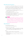
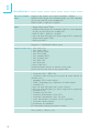
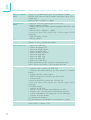
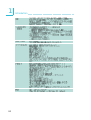
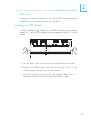
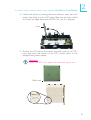
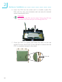
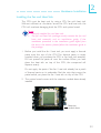
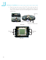
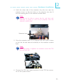
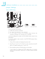
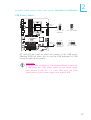
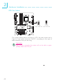
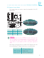
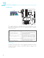
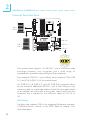
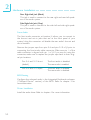
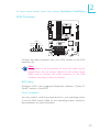
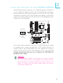
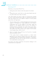
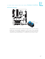
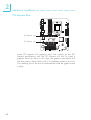
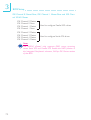
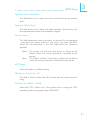
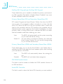
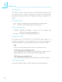
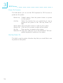
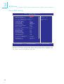
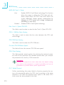
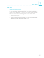
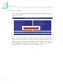
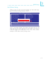
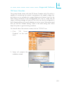
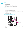
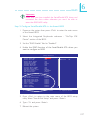
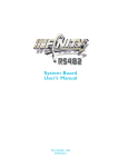
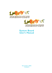
2
Hardware Installation
Universal Serial Bus Ports
USB 1
W
W
USB 0
USB 8-9
USB 3
USB 4-5
USB 2
VCC
-Data
+Data
GND
N. C.
W
USB 6-7
10
9
VCC
-Data
+Data
GND
Key
2
1
The system board supports 10 USB 2.0/1.1 ports. USB allows data
exchange between your computer and a wide range of
simultaneously accessible external Plug and Play peripherals.
Four onboard USB 2.0/1.1 ports (Black) are at locations CN3 (USB
0-1) and CN4 (USB 2-3) of the system board.
J34 (USB 4-5), J18 (USB 6-7) and J33 (USB 8-9) connectors allow
you to connect 6 additional USB 2.0/1.1 ports. The USB ports may
come mounted on a card-edge bracket. Install the card-edge bracket
to an available slot at the rear of the system chassis then insert the
connector that is attached to the USB port cables to J34, J18 or
J33.
BIOS Setting
Configure the onboard USB in the Integrated Peripherals submenu
(“Onboard Device” section) of the BIOS. Refer to chapter 3 for
more information.
48