1
MAX1169 Evaluation System/Evaluation Kit
Recommended Equipment—RS-232/COM
Port PC Connection Option
• MAX1169EVC16 (MAX1169EVKIT, 68HC16MODULEDIP, HSI2CMOD)
• Two DC power supplies:
+8V to +20V at 0.5A
+5V at 0.2A
• Analog signal source: 0 to +4.096V
• Windows 98/2000/XP computer with an available serial
(COM) port
• 9-pin I/O extension cable (straight-through, femaleto-male)
Procedure
Caution: Do not turn on the power until all the connections are completed.
1) Visit the Maxim website (www.maxim-ic.com/evkitsoftware) to download the latest version of the EV
kit software. Save the EV kit software to a temporary
folder and uncompress the file (if it is a .zip file).
2) Install the MAX1169 EV kit software on your computer by running the INSTALL.EXE program. The
program files are copied and icons are created for
them in the Windows Start | Programs menu.
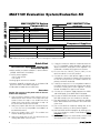
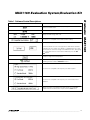
3) Verify that jumpers JU0–JU3 are connected to pins
1-2. This sets the I2C-compatible slave address of
the MAX1169 to 0x7F.
4) Verify that jumper JU4 is OFF. This enables the
internal 4.096V (typ) reference.
5) Verify that jumper JU5 is OFF. This disconnects the
analog input buffer (U2) from AIN.
6) Carefully connect the 68HC16 module board to the
HS I2C-compatible module board by aligning the
40-pin connector. Gently press them together. The
two boards should be flush against one another.
7) Ensure that the ON/OFF switch (SW1) of the
68HC16 module is in the OFF position.
8) Connect the +8V to +20V power supply to the terminal block of the 68HC16 module (J2) located next
to SW1 at the top of the µC module. Observe the
polarity marked on the board.
9) Carefully connect the HS I2C-compatible module to
the MAX1169 EV kit board by aligning the 20-pin
connector. Gently press them together. The two
boards should be flush against one another.
10) Connect the +5V power supply between the AVDD
and AGND pads on the MAX1169 EV kit board.
11) Connect the 9-pin serial cable from the computer’s
serial port to the DB9 connector of the 68HC16
module (J3).
12) Turn on the 68HC16 module by sliding SW1 to the
ON position, and turn on all the power supplies.
13) Start the MAX1169 EV kit program by clicking on its
icon in the programs section of the Windows Start |
Programs menu.
14) Press the OK button to automatically connect and
download the KIT1169.C16 file to the module.
15) The EV kit software uses the value typed in the
VREF field to translate the digital code to a voltage.
The default is a +4.096V reference value. First,
measure the reference voltage of the MAX1169.
Then, after typing the measured reference value
into the VREF field, press the Set VREF button.
16) Apply an analog input signal (0V to VREF) between
AIN and AGND. Observe the AIN voltage and code
labels on the Windows program.
_______________________________________________________________________________________
3
Evaluate: MAX1169
15) The EV kit software uses the value typed in the
VREF field to translate the digital code to a voltage.
The default is a +4.096V reference value. First,
measure the reference voltage of the MAX1169.
Then, after typing the measured reference value
into the VREF field, press the Set VREF button.
16) Apply an analog input signal (0V to VREF) between
AIN and AGND. Observe the AIN voltage and code
labels on the Windows program.