1
INSTALLATION AND
OPERATION MANUAL
ASMi-54C
Ethernet over SHDSL.bis 8-Port Module
LRS-102 Version 2.0
The Access Company
ASMi-54C
Ethernet over SHDSL.bis 8-Port Module
LRS-102 Version 2.0
Installation and Operation Manual
Notice
This manual contains information that is proprietary to RAD Data Communications Ltd. ("RAD").
No part of this publication may be reproduced in any form whatsoever without prior written
approval by RAD Data Communications.
Right, title and interest, all information, copyrights, patents, know-how, trade secrets and other
intellectual property or other proprietary rights relating to this manual and to the ASMi-54C and
any software components contained therein are proprietary products of RAD protected under
international copyright law and shall be and remain solely with RAD.
The ASMi-54C product name is owned by RAD. No right, license, or interest to such trademark is
granted hereunder, and you agree that no such right, license, or interest shall be asserted by
you with respect to such trademark. The RAD name, logo, logotype, and the terms EtherAccess,
TDMoIP and TDMoIP Driven, and the product names Optimux and IPmux, are registered
trademarks of RAD Data Communications Ltd. All other trademarks are the property of their
respective holders.
You shall not copy, reverse compile or reverse assemble all or any portion of the Manual or the
ASMi-54C. You are prohibited from, and shall not, directly or indirectly, develop, market,
distribute, license, or sell any product that supports substantially similar functionality as the
ASMi-54C, based on or derived in any way from the ASMi-54C. Your undertaking in this
paragraph shall survive the termination of this Agreement.
This Agreement is effective upon your opening of the ASMi-54C package and shall continue until
terminated. RAD may terminate this Agreement upon the breach by you of any term hereof.
Upon such termination by RAD, you agree to return to RAD the ASMi-54C and all copies and
portions thereof.
For further information contact RAD at the address below or contact your local distributor.
International Headquarters
RAD Data Communications Ltd.
North America Headquarters
RAD Data Communications Inc.
24 Raoul Wallenberg Street
Tel Aviv 69719, Israel
Tel: 972-3-6458181
Fax: 972-3-6498250, 6474436
E-mail: [email protected]
900 Corporate Drive
Mahwah, NJ 07430, USA
Tel: (201) 5291100, Toll free: 1-800-4447234
Fax: (201) 5295777
E-mail: [email protected]
© 1989–2008 RAD Data Communications Ltd.
Publication No. 416-253-12/08
Quick Start Guide
If you are familiar with the ASMi-54C modules, use this guide to prepare it for
operation.
Preparations for Operation
Warning
SFPs installed on ASMi-54C modules may be equipped with a laser diode. In such
cases, a label with the laser class and other warnings as applicable will be
attached near the optical transmitter. The laser warning symbol may be also
attached.
For your safety:
• Before turning on the equipment, make sure that the fiber optic cable is intact
and is connected to the optical transmitter.
• Do not use broken or unterminated fiber-optic cables/connectors.
• Do not look straight at the laser beam, and do not directly into the optical
connectors while the unit is operating.
• Do not attempt to adjust the laser drive current.
• The use of optical instruments with this product will increase eye hazard.
Laser power up to 1 mW could be collected by an optical instrument.
• Use of controls or adjustment or performing procedures other than those
specified herein may result in hazardous radiation exposure.
ATTENTION: The laser beam may be invisible!
1. If necessary, install the prescribed SFPs in the ASMi-54C SFP sockets.
2. Insert the module in the assigned I/O slot.
3. Refer to the site installation plan, identify the cables intended for connection
to the ASMi-54C connectors, and connect the cables as explained below.
³
To connect cables to SHDSL ports:
1. Connect the 26-pin connector of the CBL-DB26-8SHDSL cable to the module
SHDSL.bis front panel SHDSL.bis connector.
2. Connect the RJ-45 plug of each line (the plugs are marked CH-1 to CH-8) to
the prescribed user’s equipment or patch panel connector. Insulate unused
connectors, to prevent accidental short-circuiting of their exposed contacts
to metallic surfaces.
³
To connect cables to the optical Ethernet ports:
1. Connect each prescribed cable to the corresponding ASMi-54C connector,
ETH1 or ETH2. When two fibers are used, pay attention to connector polarity:
the transmitter output is at left-hand side.
ASMi-54C
LRS-102 Ver. 2.0
1
Quick Start Guide
³
Installation and Operation Manual
To connect cables to the electrical Ethernet ports:
1. Connect the prescribed cable to the corresponding connector, ETH1 or ETH2.
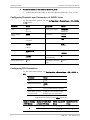
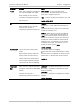
Configuring Physical Layer Parameters of SHDSL Lines
For the supervision terminal, use the Configuration > Physical layer > I/O > SHDSL
> Line screen.
Parameter
Values
Parameter
Values
Line
1 to 8
All Lines
Transmission Mode
ANNEX B/G
ANNEX A/F
Administrative
Status
DOWN
UP
Line Probe
DISABLE
ENABLE
Name
Up to 25 alphanumeric
characters
Payload Rate
192 to 5696
Wires
2 Wires
4 Wires
8 Wires
Current Margin
0 dB, -10 to +21 dB
DISABLE
TC Layer
64/65-OCTET
HDLC
Worst Margin
-10 to +21 dB
DISABLE
STU
CENTRAL
REMOTE
Loop Attenuation
Threshold (dB)
0 to 127
Power Backoff (dB)
0 to 31
SNR Margin Threshold
(dB)
0 to 15
Configuring PCS Parameters
For the supervision terminal, use Configuration > Physical layer > I/O > SHDSL >
PCS.
Parameter
Values
PCS
1 to 8
Administrative Status
DOWN
UP
Name
Up to 25 alphanumeric characters
Lines (when TC Layer
is 64/65-Octec)
Single line: same number as PCS
Multiple lines: see table below
Supported PCS Groups versus Lines Parameter
Maximum Number
of PCS Groups
2
2
Number of SHDSL Ports
(Lines) in PCS Group
SHDSL Lines in PCS
Group
Master PCS in the
Group
4
1, 2, 3, 4
1
4
5, 6, 7, 8
5
ASMi-54C
LRS-102 Ver. 2.0
Installation and Operation Manual
Maximum Number
of PCS Groups
Quick Start Guide
Number of SHDSL Ports
(Lines) in PCS Group
SHDSL Lines in PCS
Group
2
4
2
Master PCS in the
Group
1, 2
1
3, 4
3
5, 6
5
7, 8
7
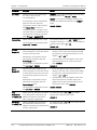
Configuring Physical Layer Parameters of Ethernet Ports
For the supervision terminal, use Configuration > Physical layer > I/O > Ethernet.
Parameter
Values
Parameter
Values
Administrative
Status
DOWN
UP
Max. Capability
Advertised
(auto-negotiation
enabled)
100Mbps full duplex
100Mbps half duplex
10Mbps full duplex
10Mbps half duplex
Name
Up to 25 alphanumeric
characters
Speed & Duplex
100Mbps full duplex
100Mbps half duplex
10Mbps full duplex
10Mbps half duplex
Auto Negotiation
ENABLE
DISABLE
Flow Control
DISABLE
ENABLE
ASMi-54C
LRS-102 Ver. 2.0
3
Quick Start Guide
4
Installation and Operation Manual
ASMi-54C
LRS-102 Ver. 2.0
Contents
Chapter 1. Introduction
1.1
1.2
1.3
1.4
Overview.................................................................................................................... 1-1
Product Options...................................................................................................... 1-1
Application ............................................................................................................. 1-1
Features ................................................................................................................. 1-2
SHDSL Transport ................................................................................................ 1-2
Ethernet Service ................................................................................................. 1-3
Capacity ............................................................................................................. 1-4
Support for Inband Management ........................................................................ 1-5
Physical Description ................................................................................................... 1-6
Functional Description................................................................................................ 1-7
Functional Block Diagram ........................................................................................ 1-7
SHDSL Subsystems ................................................................................................. 1-8
SHDSL Modems .................................................................................................. 1-8
Payload Multiplexer ............................................................................................ 1-9
Ethernet Traffic Processor ................................................................................ 1-10
Ethernet Subsystem .............................................................................................. 1-10
ASMi-54C Ethernet Handling Subsystem ........................................................... 1-10
Main Ethernet Switch Capabilities ..................................................................... 1-11
Ethernet Port Interfaces ................................................................................... 1-11
Timing Subsystem ................................................................................................. 1-12
Local Management Subsystem .............................................................................. 1-12
Diagnostics ........................................................................................................... 1-12
Technical Specifications............................................................................................ 1-13
Chapter 2. Installation and Setup
2.1
2.2
Installing the Module .................................................................................................. 2-1
Preparations for Installation .................................................................................... 2-1
Installing an SFP ................................................................................................. 2-2
Replacing an SFP ................................................................................................ 2-3
Module Installation Procedure ................................................................................. 2-4
Connecting to ASMi-54C Modules ............................................................................... 2-4
Connecting to Electrical Ethernet Ports.................................................................... 2-4
Connecting to Optical Ethernet Ports ...................................................................... 2-4
Connecting Cables to SHDSL Ports .......................................................................... 2-4
Chapter 3. Configuration
3.1
3.2
3.3
3.4
3.5
3.6
3.7
ASMi-54C
Normal Indications ..................................................................................................... 3-1
Default Settings ......................................................................................................... 3-1
ASMi-54C Configuration Sequence .............................................................................. 3-2
Outline of Configuration Sequence .......................................................................... 3-2
Configuration Guidelines and Considerations ........................................................... 3-4
Including an ASMi-54C in LRS-102 Database ............................................................... 3-4
Configuring Physical Layer Parameters of SHDSL Lines ................................................ 3-5
Configuring SHDSL Line Parameters......................................................................... 3-5
Configuring PCS Parameters .................................................................................. 3-10
Configuring Physical Layer Parameters of Ethernet Ports .......................................... 3-12
Configuring Ethernet Services ................................................................................... 3-13
LRS-102 Ver. 2.0
i
Table of Contents
Installation and Operation Manual
Chapter 4. Troubleshooting and Diagnostics
4.1
4.2
4.3
4.4
Monitoring Performance ............................................................................................. 4-1
Monitoring SHDSL Ports (Lines) ............................................................................... 4-2
Displaying SHDSL Line Status.............................................................................. 4-2
Displaying SHDSL Line Performance Monitoring Statistics .................................... 4-3
Monitoring Ethernet Ports ....................................................................................... 4-6
Displaying Ethernet Port Status .......................................................................... 4-6
Displaying Ethernet Performance Monitoring Statistics........................................ 4-7
Handling Alarms ....................................................................................................... 4-10
Troubleshooting ....................................................................................................... 4-10
Technical Support .................................................................................................... 4-11
Appendix A. Pinouts
ii
ASMi-54C
LRS-102 Ver. 2.0
Chapter 1
Introduction
1.1
Overview
This manual describes the technical characteristics, applications, installation and
operation of the ASMi-54C SHDSL.bis I/O modules for the LRS-102 high-density
SNMP managed modem rack.
ASMi-54C modules are primarily intended to operate in a link with the ASMi-54
G.SHDSL.bis standalone modems offered by RAD, to provide a simple and lowcost connectivity solution for delivering Ethernet data to customer’s premises
over the existing twisted pair (copper) infrastructure of the distribution plant,
while eliminating the need for repeaters. Each ASMi-54C module can connect to
up to eight ASMi-54 standalone modems, however it can also operate in a link
with another ASMi-54C module.
For details regarding the integration of ASMi-54C modules in LRS-102 systems and
systems applications, refer to the LRS-102 Installation and Operation Manual.
Product Options
ASMi-54C has eight independently configurable SHDSL.bis external ports for
SHDSL services, and two 10/100 Mbps Ethernet ports for packet-based services
(with license-based activation), with internal Ethernet switching subsystem. It is
offered in two models with similar characteristics, which differ only in the type of
interfaces supported by the Ethernet ports:
•
ASMi-54C/ETH/UTP: 10/100BASE-TX interfaces terminated in RJ-45
connectors.
•
ASMi-54C/ETH/SFP: two sockets for Fast Ethernet SFP optical transceivers.
RAD offers several types of SFPs capable of meeting a wide range of
operational requirements.
Application
Installing ASMi-54C modules connected to ASMi-54 standalone modems enhances
the LRS-102 capabilities and services by offering cost-effective high-speed
Ethernet access over SHDSL, at ranges up to several kilometers, based on the
Ethernet for the First Mile (EFM) standard per IEEE 802.3-2005. ASMi-54C is
capable of operating at variable rates up to 5.7 Mbps over one twisted pair, and
supports bonding of 2 and 4 twisted pairs for rates up to 22.8 Mbps.
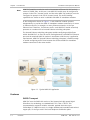
Figure 1-1 shows a typical application for an LRS-102 equipped with ASMi-54C
modules connected to ASMi-54 standalone modems.
ASMi-54C
LRS-102 Ver. 2.0
Overview
1-1
Chapter 1 Introduction
Note
Installation and Operation Manual
ASMi-54C modules can also be used to interconnect different LRS-102 units by
means of SHDSL links. In this case, one ASMi-54C module must be configured to
operate in the STU-C (central) mode, and the other ASMi-54C module(s) must be
configured to operate in the STU-R (remote) mode. The traffic handling
capabilities are similar to what is available with ASMi-54 standalone modems.
In the configuration shown in Figure 1-1, each ASMi-54C module operates
independently, to provide the ASMi-54 standalone modem connected to it access
to Ethernet services, for example, to metro Ethernet networks, at the Fast
Ethernet level. Therefore, for Ethernet traffic, each ASMi-54C module effectively
operates as a modem with an internal Ethernet switching subsystem.
The internal Ethernet switching subsystem enables configuring multiple flows
within the ASMi-54C, to filter the traffic flowing between each ASMi-54C Ethernet
port and the attached ASMi-54 modem in accordance with the user’s application
requirements. ASMi-54C internal Ethernet switching subsystem is flexible enough
to enable configuring traffic flows between the different ASMi-54 standalone
modems connected to the same module.
Figure 1-1. Typical ASMi-54C Application
Features
SHDSL Transport
ASMi-54C uses the SHDSL.bis version of the Symmetrical High-speed Digital
Subscriber Line technology, as standardized in ITU-T Rec. G.991.2. This
recommendation supports variable, extended, payload data rates up to
5.696 Mbps (5.7 Mbps line rate) on a single unloaded and unconditioned twisted
copper pair, of the type used in the local telephone distribution plant.
1-2
Overview
ASMi-54C
LRS-102 Ver. 2.0
Installation and Operation Manual
Chapter 1 Introduction
The type of SHDSL interfaces provided by the module: central (STU-C: SHDSL
terminal unit – CO) or remote (STU-R: SHDSL terminal unit – remote), as well as
the transport bandwidth, are selected by software, and the module handles all
the signal processing, framing and signaling processing tasks necessary for
SHDSL.bis interoperability.
ASMi-54C modules can be configured by the user to operate either in accordance
with ITU-T Rec. G.991.2 Annex A or F for compatibility with North American (or
similar) networks, or Annex B or G for compatibility with European (and similar)
networks.
Each of the eight SHDSL.bis module ports is supported by a multirate modem that
operates at independently user-selectable data rates in the range of 192 to
5696 kbps in 64 kbps increments. Each group of four SHDSL.bis ports (1 to 4,
and 5 to 8) is handled by a separate SHDSL section.
Note
The terms SHDSL port and SHDSL line are both used below, in accordance with
the conventions used on ASMi-54C supervision terminal screens. However, note
that the terms are interchangeable only when the SHDSL transport function (the
SHDSL line) is handled by a single port: when more ports are used, for example,
by bonding, PAF, etc., the term line represents the group of ports that provide
the transport function.
ASMi-54C supports two types of Transmission Convergence (TC) layers:
•
64/65 octet encapsulation: supports only packet traffic, that is, only
Ethernet services. Each SHDSL port operates as an independent port (2-wires
mode only), but the total bandwidth available for carrying Ethernet traffic
can be increased by bonding together two or four lines (4-wires and 8-wires
mode, respectively), using the PAF (PME Aggregation Function) defined in
IEEE 802.3-2005. Bonding enables achieving line rates up to 22.8 Mbps, or
operating at a longer range by selecting a lower rate.
•
HDLC encapsulation: to increase available bandwidth or extend the maximum
range at a given rate, it is possible to bond together two or four lines
(4-wires and 8-wires mode, respectively), a capability referred to as the
M-pair mode per ITU-T Rec. G.991.2.
Ethernet Service
ASMi-54C Ethernet services are supported by the SHDSL transport subsystem and
an internal Ethernet switching subsystem.
•
Ethernet transport over SHDSL is provided in accordance with the Ethernet in
the First Mile (EFM) standards, covered by IEEE 802.3-2005.
Ethernet traffic can be encapsulated using the 64/65-octet TPS-TC
(Transmission Protocol Specific – Transmission Convergence) layer as
standardized in IEEE 802.3-2005, or HDLC.
When ASMi-54C provides only Ethernet services, Ethernet traffic is always
encapsulated using the 64/65-octet TPS-TC. With this encapsulation, line
probing according to ITU-T Rec. G.991.2 can be enabled, to automatically
adapt the SHDSL line rate to the condition of the line (noise, loop
attenuation, etc.). When line probing is disabled, the SHDSL line operates at a
fixed rate selected by the user.
ASMi-54C
LRS-102 Ver. 2.0
Overview
1-3
Chapter 1 Introduction
Installation and Operation Manual
As mentioned above, PAF can be used to bond several SHDSL lines, where
each line can operate at a different rate. Bonding is possible only for lines
handled by the same SHDSL section (either the section handling ports 1 to 4,
or ports 5 to 8).
A significant advantage of bonding per IEEE 802.3-2005 is that a failure of a
SHDSL line does not drop the traffic being transmitted over the other wires in
the bonded group.
•
The forwarding of Ethernet traffic is handled by the internal Layer 2 Ethernet
switching subsystem that fully complies with the IEEE 802.3/Ethernet V.2
standards, and has full VLAN support in accordance with IEEE 802.1Q and
802.1p. The Ethernet switch serves both traffic and management: traffic is
supported by means of the two external Ethernet ports of the module and
by internal ports connected to the SHDSL lines, and management is
supported by a dedicated port internally connected to the ASMi-54C
management subsystem, and by another Fast Ethernet port connected to
the management handling section of the CL modules installed in the LRS-102
(this section is available on all CL modules).
The internal Ethernet switching subsystem enables forwarding traffic
between the external Ethernet ports and the SHDSL lines. The internal
forwarding of Ethernet traffic can be configured in two ways:
By specifying the ports (a mode identified as unaware in accordance with
Metro Ethernet Forum (MEF) standards). In this mode, all the Ethernet
traffic reaching one of the ports is forwarded to the other port, and vice
versa
By using VLANs for classification: (a mode identified as aware in
accordance with Metro Ethernet Forum (MEF) standards). In this mode,
Ethernet traffic reaching one of the ports is forwarded to another port in
accordance with its VLAN identifier.
Capacity
A LRS-102 chassis can contain up to 12 ASMi-54C modules. The number of
ASMi-54 standalone modems that can be connected to a single ASMi-54C module
depends on the application requirements versus SHDSL range/bandwidth
considerations:
•
When a single pair is sufficient to meet the transmission requirements, each
SHDSL port can be connected to a separate ASMi-54 standalone modem, for
a maximum of 96 modems per LRS-102 chassis.
•
When more pairs are needed for each SHDSL line to reach the required
bandwidth/range performance, either two or four pairs can be combined:
When all lines use the 4-wires modes, the total number is four ASMi-54
per ASMi-54C and a total of 48 modems per LRS-102 chassis
When all lines use the 8-wires modes, the total number is two ASMi-54
per ASMi-54C and a total of 24 modems per LRS-102 chassis.
A LRS-102 chassis equipped to its full capacity (12 modules) with ASMi-54C
modules can thus provide links to 24 ASMi-54 standalone modems, for a total
capacity of 24 Ethernet ports per chassis (2.4 Gbps per chassis).
1-4
Overview
ASMi-54C
LRS-102 Ver. 2.0
Installation and Operation Manual
Note
Chapter 1 Introduction
When only up to 8 ASMi-54C cards are planned for the chassis operation, a
separate low-consumption power supply can be ordered from RAD (see ASMi-54C
Data Sheet).
The total Ethernet traffic handling capacity of each ASMi-54C depends on the
SHDSL line rates. The maximum is always 2 × 22.8 Mbps each (approx. 45 Mbps),
irrespective of the number of pairs used for SHDSL transmission.
In general, the above-mentioned capacities should be interpreted as average
capacities; the peak traffic handling value may be much higher, considering the
statistical characteristics of the customer’s Ethernet traffic reaching the module
ports, and the effects of activating the flow control option (independently
configurable for each external Ethernet port).
Support for Inband Management
ASMi-54C supports the transfer of inband management traffic for Ethernet
applications. Inband management over ASMi-54C Ethernet ports (both external
and SHDSL-based) is possible by configuring the desired ports in the
management flow configured by the user (LRS-102 supports up to 64 bridge
ports in the management flow).
ASMi-54C
LRS-102 Ver. 2.0
Overview
1-5
Chapter 1 Introduction
Installation and Operation Manual
1.2
Physical Description
ASMi-54C modules occupy one I/O slot in the LRS-102 chassis. Typical panels are
shown in Figure 1-2.
ASMi-54C
ASMi-54C
S
H
D
S
L
.
b
i
s
S
H
D
S
L
.
b
i
s
Figure 1-2. Typical Module Panels
LASER
CLASS
1
ACT
ACT
1
1
E
T
H
E
T
H
2
2
LINK
LINK
ASMi-54C with
Copper
Ethernet Ports
ASMi-54C with
Ethernet Ports
Equipped with SFPs
The module panels include:
1-6
•
26-pin D-type female connector, designated SHDSL.bis, for connecting to all
the SHDSL ports.
•
Ethernet interfacing section: includes two Ethernet ports, designated ETH1
and ETH2. The ports are equipped either with SFPs, or terminated in RJ-45
connectors. Each port has its own set of ACT and LINK status indicators. The
functions of the ETH port status indicator are as follows:
ACT (yellow): flashes in accordance with the transmit and/or receive
activity on the corresponding port
LINK (green): lights when the link integrity signal is detected by the
corresponding port (normal operating condition).
Physical Description
ASMi-54C
LRS-102 Ver. 2.0
Installation and Operation Manual
1.3
Chapter 1 Introduction
Functional Description
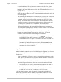
Functional Block Diagram
Figure 1-3 shows the functional block diagram of the ASMi-54C module.
ASMi-54C
SHDSL Subsystem 1
SHDSL
Modem 1
Multiplexer
.
.
.
.
.
PCS 1
Ethernet
Traffic
Processor
SHDSL
Modem 4
Line 1
.
.
.
.
.
Line 4
..
.
PCS 4
SHDSL Subsystem 2
Multiplexer
SHDSL
Modem 5
PCS 5
Ethernet
Traffic
Processor
.
.
.
.
.
SHDSL
Modem 8
Line 5
.
.
.
.
.
Line 8
.
..
..
.
..
.
PCS 8
SHDSL Subsystem
Ethernet Switch
Management Bus
Control
Local
Management
Ethernet
Transceiver
ETH1
Ethernet
Transceiver
ETH2
Main
Ethernet
Switch
Internal
Timing
Generator
Internal
Clock & Timing
Signals
Figure 1-3. ASMi-54C Functional Block Diagram
The ASMi-54C module includes the following main subsystems:
•
ASMi-54C
SHDSL subsystems, including the following functions:
SHDSL modems
Payload multiplexer
Ethernet traffic processor
LRS-102 Ver. 2.0
Functional Description
1-7
Chapter 1 Introduction
•
Installation and Operation Manual
Ethernet subsystem, including the following functions:
Main Ethernet switch
Ethernet switch for access to the SHDSL subsystem
External Ethernet port interfaces (transceivers)
•
Timing subsystem, including the internal timing generator
•
Local management subsystem.
SHDSL Subsystems
ASMi-54C includes two identical, independently-operating SHDSL subsystems,
each handling four lines: one for lines 1 to 4, and the other for lines 5 to 8.
The SHDSL subsystems comply with the applicable SHDSL.bis sections of ITU-T
Rec. G.991.2 (2004). See the SHDSL Transport section on page 1-2 for a
description of SHDSL subsystem characteristics and capabilities. The type of
SHDSL interfaces provided by the module, central (STU-C) or remote (STU-R), is
user-selectable:
Note
•
In the STU-C mode, the SHDSL subsystem handles the SHDSL link activation,
which includes the handshaking and synchronization processes needed to
set up a link between the STU-C and the STU-R in accordance with the SHDSL
parameters selected by the user. The subsystem operating in the STU-C
mode also provides the timing reference for the generation of SHDSL line
signals.
•
In the STU-R mode, the SHDSL subsystem performs similar activities, except
that its operation is coordinated by the STU-C, and the SHDSL subsystem
timing is locked to the clock recovered from the line signal.
An ASMi-54C module can operate as STU-R only if the far-end equipment is
another LRS-102 (which must include an ASMi-54C module serving as STU-C).
SHDSL Modems
Each SHDSL modem includes two main sections: a digital processor that prepares
the transmit data stream sent to the line and demultiplexes the data stream
received from the line, and an SHDSL line interface that generates the transmit
line signal and regenerates the received line signal.
•
The transmit path of the digital processor accepts the transmit payload
stream from the payload multiplexer, and then adds the SHDSL overhead to
form a standard SHDSL.bis signal with variable rate, from a minimum of
200 kbps to a maximum of 5700 kbps.
The main types of SHDSL overhead are: framing data, error detection and
correction data (also used for performance monitoring), and an embedded
operations channel (eoc) that enables the STU-C function to control the
STU-R function of the remote equipment connected to the corresponding
port. The SHDSL line interface section of the modem then encodes the
resulting data stream in accordance with the user-specified parameters (line
data rate and regional characteristics), and transmits the resulting signal to
the external line.
1-8
Functional Description
ASMi-54C
LRS-102 Ver. 2.0
Installation and Operation Manual
Chapter 1 Introduction
In general, the line rate is determined by the number of payload timeslots
that need to be transmitted over the line served by the corresponding
modem, which is user-selectable from a minimum of 3 timeslots to a
maximum of 89 timeslots.
Note
If the number of timeslots routed to the corresponding port is lower than the
maximum rate, any unused timeslots in the SHDSL signal frame is filled with the
idle timeslot code.
Because of the modulation method used by SHDSL modems, a lower rate
reduces the bandwidth needed on the external SHDSL line, and thus enables
operation over longer ranges (it also reduces the power consumption of the
ASMi-54C module).
Note
Another way to increase range is to use multiple-pair bonding (M-pair mode
defined in ITU-T Rec. G.991.2), which distributes the available traffic over two or
four twisted pairs.
The minimum payload data rate supported by an SHDSL signal, however, is
192 kbps (corresponding to three timeslots on the SHDSL line), which results,
together with the SHDSL overhead (8 kbps) in a minimum line rate of
200 kbps. Therefore, you cannot select data rates lower than 192 kbps.
However, for packet applications (that is, when only Ethernet traffic is
transmitted over the line), it is possible to allow the modem configured as
STU-C to automatically select the highest possible line rate, by performing a
special handshaking process in cooperation with the STU-R modem (line
probing in accordance with ITU-T Rec. G.991.2). This process can also be used
to renegotiate the line rate when the performance is degraded by noise, and
thus it also enables adapting to varying operating conditions. Line probing
can be used only when using the 64/65-octet TC layer.
•
The receive path of the SHDSL modem line interface section regenerates the
line signal and recovers the data stream transmitted by the STU-R. The
recovered SHDSL data stream is then processed by the receive path of the
digital processor, which decodes and demultiplexes the data stream to
retrieve the various types of data sent by the STU-R. The payload is sent to
the payload multiplexer, and the overhead data is used internally.
The receive path of the SHDSL modem can provide performance statistics for
evaluating SHDSL line transmission quality.
Payload Multiplexer
The payload multiplexer participates in the bonding of several SHDSL lines (two or
four lines) to operate as a single logical link (4-wires and 8-wires mode,
respectively), a capability referred to as the M-pair mode per ITU-T Rec. G.991.2.
For this mode, which is available when using the HDLC TC (Transmission
Convergence) layer (see the Ethernet Service section on page 1-3), the payload
multiplexer distributes the payload among the bonded SHDSL lines. All the lines
must use identical SHDSL parameters, and therefore, when lines are bonded, one
of the lines (the line with the lowest port index in the group) is automatically
selected as the master line, from which all the other lines copy their parameters.
ASMi-54C
LRS-102 Ver. 2.0
Functional Description
1-9
Chapter 1 Introduction
Installation and Operation Manual
Ethernet Traffic Processor
Each Ethernet traffic processor provides four independently-configurable Physical
Coding Sublayers (PCSs as defined in IEEE 802.3-2005), one for each SHDSL line
in the corresponding group (1 to 4 or 5 to 8). In IEEE 802.3-2005 terminology,
each PCS is associated with a PME (Physical Medium Entity): for ASMi-54C
modules, the PME is an SHDSL line (when using the M-pair mode, the PME is the
SHDSL master line).
The main functions performed for each PCS include:
Note
•
Ethernet payload data rate matching: the average payload rate accepted by
each PCS is matched to the physical rate supported by the corresponding
PME.
•
PAF (PME Aggregation Function), defined in IEEE 802.3-2005. PAF creates
PCS groups (two or four, as selected by the user) that enable increasing the
available bandwidth when using the 64/65-octet TC layer. As for M-pair
bonding, one of the PCSs (the PCS with the lowest index in the group) is
automatically selected as the master PCS, from which all the other PCSs copy
their parameters.
•
TC encapsulation, in accordance with the user-selected mode (64/65-octet
or HDLC).
Each active PCS can serve as a bridge port that can terminate Ethernet flows.
Ethernet Subsystem
ASMi-54C Ethernet services are supported by configuring flows within the
LRS-102 (flows are a generic type of Ethernet virtual connections that
interconnect user-specified bridge ports). For an overview of Ethernet services,
refer to the LRS-102 Installation and Operation Manual.
Two types of bridge ports can be defined on an ASMi-54C module:
•
Each PCS configured on the module SHDSL ports.
•
Each Ethernet physical port can also serve as a bridge port.
The maximum number of bridge ports that can be defined on an ASMi-54C
module, together with the two Ethernet ports, is up to 10.
ASMi-54C Ethernet Handling Subsystem
The functional block diagram of the ASMi-54C local Ethernet handling subsystem
is shown in Figure 1-3. This subsystem includes:
1-10
•
Ethernet port interfaces: provide 10/100 Mbps physical interfaces for
external Ethernet links.
•
Main layer 2 Ethernet switch: provides the local Ethernet classification and
switching functions. The Ethernet switch determines the destination of each
frame in accordance with the configured flows. The classification of each
user network is based on the VLAN ID, or on the port, if no C-VLAN is
configured.
Functional Description
ASMi-54C
LRS-102 Ver. 2.0
Installation and Operation Manual
•
Note
Chapter 1 Introduction
SHDSL Ethernet switch: a layer 2 switch that handles the traffic directed to
SHDSL lines, through the PCS ports (the traffic handled by this switch is
forwarded by the main Ethernet switch). Using a separate switch provides
the flexibility needed to operate the required number of PCS ports.
LRS-102 supports traffic and management flows. ASMi-54C bridge ports can also
serve the management flow. Unless specifically mentioned otherwise, in this
manual the term flow means traffic flow.
Main Ethernet Switch Capabilities
The function of the ASMi-54C main Ethernet switch is to route traffic between
external Ethernet ports and internal Ethernet ports, in accordance with the
configuration parameters specified by the user. The Ethernet switch fully
complies with the IEEE 802.3/Ethernet V.2 standards, and has full VLAN support
in accordance with IEEE 802.1Q and 802.1p. The switch has memory-based
switch fabric with true non-blocking switching performance. The switch collects a
wide range of performance monitoring parameters, which can be read by
management.
The Ethernet switch ports are used as follows:
•
Connection to the ETH 1 and ETH 2 external port transceivers.
•
Connection to the Ethernet switch serving the SHDSL subsystem, for
transferring the traffic directed through the PCS ports to the SHDSL lines
•
One of the Fast Ethernet ports without transceivers is connected, via the
local management subsystem, to the management handling section of the
CL modules installed in the LRS-102 (this section is available on all CL
modules). One management port connects to the ASMi-54C local
management subsystem.
Each switch port is supported by an independent MAC controller that performs all
the functions required by the IEEE 802.3 protocol. The frames passed by the MAC
controller are analyzed by the ingress policy controller of the corresponding port
before being transferred to an internal queue controller, which controls the
frame egress priorities and inserts them in separate queues. The queues are
connected to the ports through the port egress policy controllers. This approach
provides full control over traffic flow, and ensures that congestion at one port
does not affect other ports.
Ethernet Port Interfaces
The external Ethernet ports have 10/100 Mbps interfaces capable of
auto-negotiation. The user can configure the advertised data rate (10 or
100 Mbps) and operating mode (half-duplex or full-duplex). Alternatively,
auto-negotiation can be disabled, and the rate and operating mode be directly
specified.
The Ethernet ports can be ordered with one of the following types of interfaces:
•
ASMi-54C
Sockets for SFP Fast Ethernet transceivers. RAD offers several types of
SFPs with optical interfaces, for meeting a wide range of operational
requirements (SFPs with copper interfaces are also available). The SFPs
are hot-swappable.
LRS-102 Ver. 2.0
Functional Description
1-11
Chapter 1 Introduction
Installation and Operation Manual
•
10/100BASE-TX interfaces terminated in RJ-45 connectors. In addition to
auto-negotiation, MDI/MDIX polarity and cross-over detection and
automatic cross-over correction are also supported. Therefore, these
ports can always be connected through a “straight” (point-to-point) cable
to any other type of 10/100BASE-T Ethernet port (hub or station).
Timing Subsystem
The timing subsystem generates the clock and timing signals required by the
transmit paths of the module.
Local Management Subsystem
The local management subsystem performs three main functions:
•
Controls the operation of the various circuits located on the ASMi-54C module
in accordance with the commands received from the CL module through the
LRS-102 management channel.
The management subsystem in an ASMi-54C module cannot manage remote
units connected to SHDSL ports through the eoc.
•
Stores the application software of the ASMi-54C module. The software can be
updated through the CL module.
•
Controls the routing of management traffic through the desired link
interfaces, in accordance with the management mode selected by the user for
each link interface.
ASMi-54C Ethernet ports and bundles can also support inband management,
when attached to the LRS-102 management flow.
Diagnostics
Performance statistics for the SHDSL and Ethernet ports may be obtained and
analyzed via the LRS-102 management system.
The ASMi-54C ports support the collection of performance diagnostics in
accordance with the requirements of ITU-T Rec. G.991.2.
1-12
Functional Description
ASMi-54C
LRS-102 Ver. 2.0
Installation and Operation Manual
1.4
Chapter 1 Introduction
Technical Specifications
General
Number of Ports
8
External SHDSL.bis
Port
Port Interface Type
SHDSL
Signal Format
TC-PAM32
Applicable Standards
ITU-T Rec. G.991.2, ETSI TS 101524
Port Type
Software configurable for all the ports:
• Central (STU-C) – default mode
• Remote (STU-R)
Line Type
Single unloaded, unconditioned copper twisted
pair, 26 AWG or thicker
Nominal Line Impedance
135 Ω
Range at 26 AWG,
noise-free
See Table 1-1
Table 1-1. Range by Data Rate
Data Rate*
Range
[kbps]
[km]
[miles]
192
6.4
4.0
1024
5.5
3.4
2048
3.8
2.4
4096
3.5
2.2
5696
2.5
1.5
*26 AWG, noise-free
Port Timing
• STU-C: locked to LRS-102 station clock
• STU-R: locked to the line signal received from
the STU-C
• Internal
Connector
Ethernet Interfaces Number of Ports
ASMi-54C
LRS-102 Ver. 2.0
DB-26 convertible to 8 RJ-45 connectors via
adaptor cable. Adapter cables available from RAD
Two ports (either fiber-optic or copper, in
accordance with order)
Technical Specifications
1-13
Chapter 1 Introduction
Installation and Operation Manual
Data Rate
• 10/100 Mbps (Fast Ethernet)
• Autonegotiation
Total Bandwidth per
Module
100 Mbps per module
Maximum Frame Size
1600 bytes
Fiber Optic Ports
Hot-swappable SFPs
Note: For detailed specifications of the SFP
transceivers, see the SFP Transceivers data
sheet
Copper Ports
Interface Type
10/100Base-TX
Connector
Shielded RJ-45
Indicator functions (per
Ethernet port)
Diagnostics
Performance Monitoring
Configuration
1-14
Technical Specifications
•
ACT (yellow): flashes in accordance with the
transmit and/or receive activity on the
corresponding port
LAN data activity
•
LINK (green): lights when the link integrity
signal is detected by the corresponding port
LAN link integrity
In accordance with ITU-T Rec. G.991.2, G.826
Programmable via LRS-102 management system
ASMi-54C
LRS-102 Ver. 2.0
Chapter 2
Installation and Setup
This Chapter provides installation and setup instructions for ASMi-54C modules.
ASMi-54C connector pin functions and the wiring of the relevant cables are
presented in Appendix A.
The information presented in this Chapter supplements the general LRS-102
installation, configuration and operation instructions contained in the LRS-102
Installation and Operation Manual.
2.1
Warning
Caution
Installing the Module
Before performing any internal settings, adjustment, maintenance, or repairs,
first disconnect all the cables from the module, and then remove the module
from the LRS-102 enclosure.
No internal settings, adjustment, maintenance, and repairs may be performed by
either the operator or the user; such activities may be performed only by a skilled
technician who is aware of the hazards involved.
Always observe standard safety precautions during installation, operation, and
maintenance of this product.
The ASMi-54C module contains components sensitive to electrostatic discharge
(ESD). To prevent ESD damage, always hold the module by its sides, and do not
touch the module components or connectors.
Caution To prevent physical damage to the electronic components assembled on the two
sides of the module printed circuit boards (PCB) while it is inserted into its
chassis slot, support the module while sliding it into position and make sure that
its components do not touch the chassis structure, nor other modules.
ASMi-54C modules may be installed in an operating chassis (hot insertion).
Note
ASMi-54C software can be updated by downloading from the CL module.
Therefore, if the ASMi-54C module is not yet loaded with the required software
version, refer to Appendix B of the LRS-102 Installation and Operation Manual for
detailed software downloading instructions.
Preparations for Installation
No preparations are required for ASMi-54C modules with UTP Ethernet ports,
terminated in RJ-45 connectors.
ASMi-54C
LRS-102 Ver. 2.0
Installing the Module
2-1
Chapter 2 Installation and Setup
Installation and Operation Manual
For ASMi-54C modules equipped with Ethernet ports having SFP sockets, it may
be necessary to install, or replace, SFPs. ASMi-54C modules have two installation
positions for SFPs, designated ETH1 and ETH2:
•
To install an SFP, use the procedure given in the Installing an SFP section
below.
•
SFPs may be replaced using the procedure given in the Replacing an SFP
section below.
ASMi-54C modules equipped with RAD-supplied SFP plug-in modules comply with
laser product performance standards set by government agencies for Class 1 laser
products. The modules do not emit hazardous light, and the beam is totally enclosed
during all operating modes of customer operation and maintenance.
Third-party SFP optical transceivers may be also used, provided they are
approved by an internationally recognized regulatory agency, and comply with
the national laser safety regulations for Class 1 laser equipment. However, RAD
Warning
strongly recommends ordering the ASMi-54C with RAD SFPs, as this permits full
performance testing of the supplied equipment.
ASMi-54C modules are shipped with protective covers installed on all the optical
connectors. Keep the covers for reuse, to reinstall the cover over the optical
connector as soon as the optical cable is disconnected.
Warning
SFPs installed on ASMi-54C modules may be equipped with a laser diode. In such
cases, a label with the laser class and other warnings as applicable will be
attached near the SFP socket. The laser warning symbol may be also attached.
For your safety:
• Before turning on the equipment, make sure that the fiber optic cable is intact
and is connected to the optical transmitter.
• Do not use broken or unterminated fiber-optic cables/connectors.
• Do not look straight at the laser beam, and do not look directly into the
optical connectors while the module is operating.
• Do not attempt to adjust the laser drive current.
• The use of optical instruments with this product will increase eye hazard.
Laser power up to 1 mW could be collected by an optical instrument.
• Use of controls or adjustment or performing procedures other than those
specified herein may result in hazardous radiation exposure.
ATTENTION: The laser beam may be invisible!
Installing an SFP
When installing an optical SFP in an operating module, be aware that it may
immediately start generating laser radiation.
Warning
2-2
Installing the Module
ASMi-54C
LRS-102 Ver. 2.0
Installation and Operation Manual
Chapter 2 Installation and Setup
Caution During the installation of an SFP with optical interfaces, make sure that all the
optical connectors are closed by protective caps.
Do not remove the covers until you are ready to connect optical fibers to the
connectors.
Note
³
All the following procedures are illustrated for typical SFPs with optical interfaces.
Your SFPs may look different.
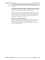
To install the SFP:
1. Lock the latch wire of the SFP module by lifting it up until it clicks into place,
as illustrated in Figure 2-1.
Note
Some SFP models have a plastic door instead of a latch wire.
Figure 2-1. Locking the Latch Wire of a Typical SFP
2. Carefully remove the dust covers from the corresponding SFP socket of the
ASMi-54C module, and from the SFP electrical connector.
3. Orient the SFP as shown in Figure 2-1, and then insert the rear end of the
SFP into the module socket.
4. Push SFP slowly backwards to mate the connectors, until the SFP clicks into
place. If you feel resistance before the connectors are fully mated, retract the
SFP using the latch wire as a pulling handle, and then repeat the procedure.
5. If necessary, repeat the procedure for the other SFP.
Replacing an SFP
SFPs can be hot-swapped. It is always recommended to coordinate SFP
replacement with the system administrator. Note that during the replacement of
SFPs, only the traffic on the affected ETH link is disrupted (the other ETH link can
continue to carry traffic).
³
To replace an SFP:
1. If necessary, disconnect any cables connected to the SFP connectors.
2. Push down the SFP locking wire, and then pull the SFP out.
3. Reinstall protective covers on the SFP electrical and optical connectors.
4. Install the replacement SFP in accordance with the Installing an SFP section.
ASMi-54C
LRS-102 Ver. 2.0
Installing the Module
2-3
Chapter 2 Installation and Setup
Installation and Operation Manual
Module Installation Procedure
The ASMi-54C module starts operating as soon as it is inserted in an operating
chassis.
Warning
³
To install an ASMi-54C module:
1. Refer to the system installation plan and identify the prescribed module slot.
2. Check that the fastening screws at the module sides are free to move.
3. Insert the ASMi-54C module in its chassis slot and slide it backward as far as
it goes.
4. Secure the ASMi-54C module by tightening its two fastening screws.
5. The module starts operating as soon as it is plugged into an operating
enclosure. At this stage, ignore the alarm indications.
2.2
Connecting to ASMi-54C Modules
Before starting, identify the cables intended for connection to each port of this
module, in accordance with the site installation plan.
Connecting to Electrical Ethernet Ports
³
To connect cables to the ASMi-54C electrical Ethernet ports:
1. Connect the prescribed cable to the corresponding connector, ETH1 or ETH2.
Connecting to Optical Ethernet Ports
Before starting, review the general optical cable handling instructions section in
Chapter 2 of the LRS-102 Installation and Operation Manual.
³
To connect cables to the optical Ethernet ports:
1. Connect each prescribed cable to the corresponding ASMi-54C connector,
ETH1 or ETH2.
When two fibers are used, pay attention to connector polarity: the
transmitter output is at left-hand side.
Connecting Cables to SHDSL Ports
Using the site installation plan, identify the cable intended for connection to the
ASMi-54C SHDSL.bis connector, and connect the cable to the module connector
as explained below.
2-4
Connecting to ASMi-54C Modules
ASMi-54C
LRS-102 Ver. 2.0
Installation and Operation Manual
³
Chapter 2 Installation and Setup
To connect the cable to the module:
1. Connect the 26-pin connector of the CBL-DB26-8SHDSL cable to the module
SHDSL.bis front panel SHDSL.bis connector.
2. Connect the RJ-45 plug of each line (the plugs are marked CH-1 to CH-8) to
the prescribed user’s equipment or patch panel connector. Insulate unused
connectors, to prevent accidental short-circuiting of their exposed contacts
to metallic surfaces.
ASMi-54C
LRS-102 Ver. 2.0
Connecting to ASMi-54C Modules
2-5
Chapter 2 Installation and Setup
2-6
Connecting to ASMi-54C Modules
Installation and Operation Manual
ASMi-54C
LRS-102 Ver. 2.0
Chapter 3
Configuration
This Chapter provides specific configuration information for ASMi-54C modules
that supplement the LRS-102 configuration instructions appearing in the LRS-102
Installation and Operation Manual.
The configuration activities are performed by means of the management system
used to control the LRS-102 unit.
For general instructions, additional configuration procedures, and background
information, refer to the LRS-102 Installation and Operation Manual.
3.1
Normal Indications
After the equipment connected to the ASMi-54C Ethernet ports is operational,
the following indications should appear for each port:
•
The LINK indicator lights as long as the port is connected to operational
equipment
•
The ACT indicator may light continuously, or flash from time to time, in
accordance with the transmit and receive activity at the corresponding port.
3.2
Default Settings
Table 3-1 lists the ASMi-54C factory-default parameters.
Table 3-1. ASMi-54C Factory-Default Parameters
Parameter
Description
Factory Default Value
SHDSL Line Physical Layer Parameters
Line
SHDSL line index number
1
Administrative Status
Port administrative status
Down
Name
Line logical name
Empty string
Wires
Number of lines (wire pairs)
2 wires
TC Layer
Transmission Convergence layer
64/65-octet
STU
Port operating mode
Central
Power Backoff
Transmit power backoff
0
ASMi-54C
LRS-102 Ver. 2.0
Default Settings
3-1
Chapter 3 Configuration
Installation and Operation Manual
Parameter
Description
Factory Default Value
Transmission Mode
Regional-dependent parameters set
Annex B/G
Line Probe
Line probing per ITU-T Rec. G.991.2
Enable
Payload Rate
Line payload rate, in kbps
192
Current Margin (dB)
Measured noise level
0
Worst Margin (dB)
Target margin for signal-to-noise ratio
Disable
Loop Attenuation
Threshold (dB)
Generation of an alarm in case the attenuation
measured on the SHDSL line exceeds a selected
threshold value
0
SNR Margin Threshold
(dB)
Generation of an alarm in case the attenuation
measured on the SHDSL line exceeds a selected SNR
margin threshold
0
PCS Parameters
PCS
PCS index number
1
Administrative Status
PCS administrative status
Down
Name
PCS logical name
Empty string
Lines
Lines in the PCS group
1
Ethernet Port Physical Layer Parameters
Port
Ethernet port index number
1
Administrative Status
Ethernet port administrative status
Down
Name
Ethernet port logical name
Empty string
Auto Negotiation
Ethernet port autonegotiation mode
Enable
Max. Capability
Advertised
Highest traffic handling capability advertised when
autonegotiation is enabled
100Mbps full duplex
Speed & Duplex
Ethernet port data rate and operating mode when
autonegotiation is disabled
100Mbps full duplex
Flow Control
Ethernet port flow control or back pressure
Disable
3.3
ASMi-54C Configuration Sequence
Outline of Configuration Sequence
Make sure to plan ahead the configuration sequence, because LRS-102 databases
can be updated only after correctly completing the configuration activities: any
sanity error will prevent saving the changes to the database being modified. For
example, a common cause of sanity errors that may prevent updating the
database is that timeslots have to be assigned to ports of other modules that will
be served by the ASMi-54C ports.
3-2
ASMi-54C Configuration Sequence
ASMi-54C
LRS-102 Ver. 2.0
Installation and Operation Manual
Chapter 3 Configuration
ASMi-54C configuration includes the following main types of tasks:
•
Tasks needed to configure an ASMi-54C module and put it into service. These
tasks include the programming of ASMi-54C modules not yet installed in
LRS-102 database, and configuring the parameters of the desired module
SHDSL ports (lines) and PCSs.
•
Tasks related to the utilization of the module TDM ports (TDM services).
•
Tasks related to the utilization of the module Ethernet ports, and the
provisioning of Ethernet services.
The recommended configuration sequence for each type of task is described
below, together with references to the supervision terminal screens used to
perform each task.
³
To configure an ASMi-54C module and put it into service (see Section 3.4):
1. If necessary, program (add) an ASMi-54C module not yet installed in the
LRS-102 chassis to the database.
For the supervision terminal, use Configuration > System > Card Type.
³
To configure the SHDSL physical layer parameters (see Section 3.5):
1. Configure the physical layer parameters for the active SHDSL ports (lines) of
the ASMi-54C module.
For the supervision terminal, use Configuration > Physical Layer > I/O > SHDSL
> Lines.
2. Configure the physical layer parameters for the active PCSs of the ASMi-54C
module.
For the supervision terminal, use Configuration > Physical layer > I/O> SHDSL
> PCS.
³
To configure the Ethernet physical layer parameters (see Section 3.6):
•
Configure the physical layer parameters for the Ethernet ports of the
ASMi-54C module.
For the supervision terminal, use Configuration > Physical Layer > I/O >
Ethernet.
³
To configure Ethernet services supported by the module bridge ports (see
Section 3.7):
•
Configure each Ethernet services flow that is terminated at a PCS or Ethernet
port defined on the ASMi-54C being configured, and map the other end to
the prescribed bridge port.
For the supervision terminal, use Configuration > Applications > Ethernet
Services > Flows (for instructions, refer to the LRS-102 Installation and
Operation Manual).
ASMi-54C
LRS-102 Ver. 2.0
ASMi-54C Configuration Sequence
3-3
Chapter 3 Configuration
Installation and Operation Manual
Configuration Guidelines and Considerations
The first step in planning the configuration sequence of ASMi-54C modules is to
select the Transmission Convergence (TC) layer to be used by the module, HDLC
or 64/65 octet encapsulation:
•
64/65 octet encapsulation: supports only packet traffic, that is, only Ethernet
services. Each SHDSL line then operates alone (2-wires mode only), but the
total bandwidth available for an Ethernet port can be increased by bonding
together several lines, using the PAF (PME Aggregation Function).
For ASMi-54C modules, PAF can combine two or four lines for serving a single
PCS. The PCS can be connected by a flow to an Ethernet port (with four lines
per PCS, two PCSs can be configured, one for each ASMi-54C Ethernet port).
•
HDLC encapsulation. To increase available bandwidth, it is possible to bond
together two or four lines (4-wires and 8-wires mode, respectively). Thus,
the maximum bandwidth for Ethernet services is obtained by configuring two
8-wires lines.
After selecting the TC layer, it is necessary to select the bandwidth, considering
the required range (see range data in Chapter 1). When range is significant, it is
recommended to consider the use of multiple lines: this can yield the same
throughput as a single line, but because a lower rate per line is used, thus
increasing the range and reducing the effects of interference and crosstalk.
After determining the general planning parameters, other configuration
parameters can be selected in accordance with the specific application
requirements.
3.4
³
Including an ASMi-54C in LRS-102 Database
To program an ASMi-54C module in the LRS-102 database:
1. Navigate to the Configuration > System > Card Type screen.
2. Bring the cursor to the field of the prescribed I/O slot by clicking <Tab>, and
select ASMi54C.
3. Update the LRS-102 database, to save the new selection (type %, and then
type y to confirm).
Note
3-4
If the programmed module is not yet installed in the LRS-102, it is normal to get
a warning message reporting a programmed/installed module mismatch.
Including an ASMi-54C in LRS-102 Database
ASMi-54C
LRS-102 Ver. 2.0
Installation and Operation Manual
3.5
Chapter 3 Configuration
Configuring Physical Layer Parameters of SHDSL
Lines
The SHDSL physical layer parameters include two groups:
•
SHDSL line parameters, which determine the transmission performance
provided by the module ports
•
PCS parameters, which determine the Ethernet (packet) physical layer
transmission capabilities over SHDSL lines.
Configuring SHDSL Line Parameters
ASMi-54C has 8 independent SHDSL ports, supported by means of two internal
SHDSL processing subsystems (one subsystem handles ports 1 to 4, and the
other – ports 5 to 8). Each port requires a 2-wire line.
Note
An ASMi-54 standalone unit supports the connection of up to four SHDSL lines,
which must always be in the same group: either 1 to 4, or 5 to 8.
In each group, ports can be configured to operate separately (2 wires mode), or
can be bonded together in groups of two ports (4 wires mode), or 4 (8 wires
mode).
Note
³
Since ports can be bonded together to provide a single transmission line, the
term line is used, instead of ports, on the supervision terminal screens.
To configure the physical layer parameters for the ASMi-54C SHDSL ports:
1. Navigate to the Configuration > Physical layer > I/O screen, and then select
the I/O slot of the desired ASMi-54C module.
2. Select the SHDSL option.
3. Select the Line option.
You will see the configuration screen for the first SHDSL line (the line
with the lowest index number). Scroll using F and B to reach the desired
port, or use the Line field to enter manually the desired port number, in
the range of 1 to 8.
Alternatively, if you will use the 2-Wires option, first preconfigure all the
lines with the same basic parameters by selecting All Lines, and then
sequentially select each line and change its parameters as required.
Table 3-2 lists the ASMi-54C SHDSL physical line parameters.
ASMi-54C
LRS-102 Ver. 2.0
Configuring Physical Layer Parameters of SHDSL Lines
3-5
Chapter 3 Configuration
Installation and Operation Manual
Table 3-2. ASMi-54C SHDSL Physical Port Parameters
Parameter
Function
Values
Rate
Displays the total SHDSL line rate,
which includes the overhead and the
payload rate.
The range is 200 to 22816 kbps
The displayed value is automatically
adjusted to the selected Wires and
Payload Rate values.
This parameter is not displayed when
Line Probe is ENABLE. Note that at the
REMOTE side, the line probing must
always be enabled, and therefore it is
not possible to select a specific rate
Selects the index number of the SHDSL The range of SHDSL lines index numbers is 1 to 8. In
addition, it is also possible to select All Lines.
line to be configured.
Line
Administrative
Status
When using multiple lines (selected by
means of the Wires parameter), only
lines that can be independently
configured are displayed: the index
numbers of lines that are grouped
together are automatically skipped.
See details in Table 3-3
Default: 1
Used to enable/disable the selected
SHDSL port (line)
UP – The selected line is enabled.
DOWN – The selected line is disabled. This state
should be selected as long as the line configuration
has not yet been completed, or when it is necessary
to stop traffic flow through the line.
Default: DOWN
Name
Wires
Used to enter a logical name for the
selected line
Up to 25 alphanumeric characters.
Default: Empty string
Selects the number of lines (wire pairs) 2 Wires – Each port operates independently. In this
bonded together to.
The number of the line is identical to the number of
The available selections depend on the the physical SHDSL port in the ASMi-54C SHDSL.bus
connector to which the line is connected.
TC Layer parameter
4 Wires – Two ports (with sequential index
numbers) are bonded together. See Table 3-3 for
details regarding the ports that support this option.
This selection is available only when TC Layer is
HDLC.
8 Wires – Four ports (with sequential index
numbers) are bonded together. See Table 3-3 for
details regarding the ports that support this option.
This selection is available only when TC Layer is
HDLC.
Default: 2 Wires
3-6
Configuring Physical Layer Parameters of SHDSL Lines
ASMi-54C
LRS-102 Ver. 2.0
Installation and Operation Manual
Chapter 3 Configuration
Parameter
Function
Values
TC Layer
Selects the Transmission Convergence
layer used by the ASMi-54C module.
64/65-OCTET – TC layer uses 64/65-octet
encapsulation. This mode supports only packet
traffic over a single line (wire pair).
All the module ports use the same
Transmission Convergence layer (the
last selection is automatically applied
to all the ports)
STU
Selects the port operating mode.
All the module ports use the same
mode (the last selection is
automatically applied to all the ports)
HDLC – TC layer uses HDLC encapsulation. This mode
enables using multiple lines (wire pairs).
Default: 64/65-OCTET
CENTRAL – ASMi-54C ports operate in the SHDSL
terminal unit – central mode (also referred to as
STU-C). This is the mode to be used when the
equipment connected to the far end of the lines is
an ASMi-54 standalone unit.
REMOTE – ASMi-54C ports operate in the SHDSL
terminal unit – remote mode (also referred to as
STU-R). This mode should be used only when the
equipment connected to the far end of the lines is
an ASMi-54C module installed in another LRS-102.
Note that in the REMOTE mode, the line probing
must always be enabled, and therefore it is not
possible to select a specific Rate.
Default: CENTRAL
Power Backoff
Controls the use of transmit power
backoff.
Power backoff is used to reduce the
transmit power below the nominal
value specified in the standards: this
reduces interference caused by your
signal to other equipment using pairs
in the same cable, without degrading
the link transmission quality
Transmission
Mode
The available selections are 0 to 31.
0 means that the nominal transmit power is always
used. Any other value indicates the maximum power
backoff value, in dB below the nominal transmit
power specified in the standards.
Default: 0
Selects the set of regional-dependent ANNEX A/F – Compliance with Annex A or F of ITU-T
parameters used by the module SHDSL Rec. G.991.2, required for compatibility in North
modems.
American networks.
All the module ports use the same
mode (the last selection is
automatically applied to all the ports)
ANNEX B/G – Compliance with Annex B or G of ITU-T
Rec. G.991.2, required for compatibility in European
networks.
Default: ANNEX B/G
ASMi-54C
LRS-102 Ver. 2.0
Configuring Physical Layer Parameters of SHDSL Lines
3-7
Chapter 3 Configuration
Installation and Operation Manual
Parameter
Function
Values
Line Probe
Controls the use of line probing per
ITU-T Rec. G.991.2 for the
corresponding line.
DISABLE – Line probing is disabled. This is the only
option available when TC Layer is HDLC.
ENABLE – Line probing is enabled. Note that line
Line probing is used to automatically
probing must always be enabled for the REMOTE
select the maximum data rate
mode.
supported by the line. When enables,
Default: ENABLE
the Payload Rate of the line is
automatically set to 192 kbps, and is
increased when line conditions permit.
This parameter is relevant only when
when TC Layer is 64/65-OCTET
Payload Rate
Selects the line payload rate, in kbps.
This parameter is not displayed when
Line Probe is ENABLE
The available selections are 192 to 5696 kbps, in
multiples of 64 kbps (n × 64 kbps, corresponding to
n values in the range of 3 to 89.
Default: 192
Current
Margin(dB)
Specifies the target margin for the
•
measured signal-to-noise ratio relative
to the current noise level.
Alternatively, line activation may be
performed in accordance with the
Worst Margin value.
This parameter is displayed only when
the Line Probe is ENABLE
Worst
Margin(dB)
•
To disable the use of the signal-to-noise ratio
measured relative to the current noise level,
select DISABLE.
Default: 0
Specifies the target margin for the
•
measured signal-to-noise ratio relative
to the reference worst-case near-end
crosstalk noise specified in ITU-T Rec.
G.991.2.
•
Alternatively, line activation may be
performed in accordance with the
Current Margin value.
This parameter is displayed only when
the Line Probe is ENABLE
To use the signal-to-noise ratio measured
relative to the current noise level during SHDSL
line activation, select the desired value, in the
range of -10 to +21 dB.
To use the signal-to-noise ratio measured
relative to the near-end crosstalk during SHDSL
line activation, select the desired value, in the
range of -10 to +21 dB.
To disable the use of the signal-to-noise ratio
measured relative to crosstalk and use the
signal-to-noise ratio measured relative to the
current noise level, select DISABLE.
Default: DISABLE
Loop
Selects the loop attenuation threshold: The allowable range is 0 to 127 (the number
Attenuation
if the attenuation measured on the
specifies the maximum value, in dB).
Threshold (dB) SHDSL link exceeds the threshold
Default: 0
value, and alarm is generated
SNR Margin
Selects the SNR margin threshold: if
The allowable range is 0 to 15 (the number specifies
Threshold (dB) the attenuation measured on the
the maximum value, in dB).
SHDSL link exceeds the specified value, Default: 0
an alarm is generated
3-8
Configuring Physical Layer Parameters of SHDSL Lines
ASMi-54C
LRS-102 Ver. 2.0
Installation and Operation Manual
Chapter 3 Configuration
Table 3-3. Supported Lines versus Wires Parameter
Line Number
Available Modes
Description
2 Wires
Line independently configurable
4 Wires
Line 1 bonded with Line 2.
Line 1 is the master line, and all its parameters will be
copied to Line 2. Line 2 and PCS 2 will not be
available to selection by the user
1
8 Wires
Line 1 bonded with Line 2, Line 3 and Line 4.
Line 1 is the master line, and all its parameters will be
copied to Line 2, Line 3, and Line 4. Line 2, 3, 4 and
PCS 2, 3, 4 will not be available for selection by the
user
2
2 Wires
Line independently configurable
2 Wires
Line independently configurable
4 Wires
Line 3 bonded with Line 4.
3
4
Line 3 is the master line, and all its parameters will be
copied to Line 4. Line 4 and PCS 4 will not be
available to selection by the user
2 Wires
Line independently configurable
2 Wires
Line independently configurable
4 Wires
Line 5 bonded with Line 6.
Line 5 is the master line, and all its parameters will be
copied to Line 6. Line 6 and PCS 6 will not be
available to selection by the user
5
8 Wires
Line 5 bonded with Line 6, Line 7 and Line 8.
Line 5 is the master line, and all its parameters will be
copied to Line 6, Line 7 and Line 8. Line 6, 7, 8 and
PCS 6, 7, 8 will not be available for selection by the
user
6
2 Wires
Line independently configurable
2 Wires
Line independently configurable
4 Wires
Line 7 bonded with Line 8.
7
8
ASMi-54C
LRS-102 Ver. 2.0
Line 7 is the master line, and all its parameters will be
copied to Line 8. Line 8 and PCS 8 will not be
available to selection by the user
2 Wires
Line independently configurable
Configuring Physical Layer Parameters of SHDSL Lines
3-9
Chapter 3 Configuration
Installation and Operation Manual
Configuring PCS Parameters
PCSs are defined in IEEE 802.3-2005. In LRS-102 they are used to transport
Ethernet traffic from a local Ethernet port over SHDSL.
The ASMi-54C internal SHDSL processing subsystem enables to configure for each
SHDSL line (actually – for each SHDSL port) the desired Physical Coding Sublayer
parameters. Therefore, ASMi-54C supports 8 PCS entities, one for each
associated SHDSL port, and on the supervision terminal screens, the PCS index
number is the same as the associated SHDSL port.
As for SHDSL ports, PCSs are processed in two groups of four (one group includes
PCSs 1 to 4, and the other – PCSs 5 to 8).
Note
An ASMi-54 standalone unit supports the connection of up to four PCSs, which
must be in the same group (either 1 to 4, or 5 to 8).
The PCSs are independently configurable, except that only PCSs associated with
master lines (see Table 3-3) can be selected.
In IEEE 802.3-2005 terminology, each PCS is associated with a PME (Physical
Medium Entity): for ASMi-54C modules, it is the SHDSL master line.
The PCS bandwidth depends on the rate provided by the associated line:
•
When using the 64/65-octet TC layer, the available bandwidth is the payload
rate of the associated line. This bandwidth is a maximum of 22784 kbps
(when using the 8-wires mode with four SHDSL ports operating at the
maximum rate, 5696 kbps).
•
When using the HDLC TC layer, the available bandwidth is the payload rate of
the associated line, less any bandwidth assigned to the associated internal
DS1 port of the same line.
Even when all the eight SHDSL lines of the ASMi-54C module operate in the
2 Wires mode (see Table 3-2), the PCS transport bandwidth can be increased
using PAF (PME Aggregation Function), also defined in IEEE 802.3-2005. PAF
creates PCS groups. The PCS groups that can be configured on the ASMi-54C are
listed in Table 3-4.
Table 3-4. Supported PCS Groups versus Lines Parameter
Maximum Number
of PCS Groups
2
Number of SHDSL Ports
(Lines) in PCS Group
SHDSL Lines in PCS
Group
4
1, 2, 3, 4
1
4
5, 6, 7, 8
5
1, 2
1
3, 4
3
5, 6
5
7, 8
7
2
4
2
3-10
Configuring Physical Layer Parameters of SHDSL Lines
Master PCS in the
Group
ASMi-54C
LRS-102 Ver. 2.0
Installation and Operation Manual
³
Chapter 3 Configuration
To configure the PCS parameters:
1. Navigate to the Configuration > Physical layer > I/O screen, and then select
the I/O slot of the desired ASMi-54C module.
2. Select the SHDSL option.
3. Select the PCS option.
You will see the configuration screen for the first PCS (the PCS with the
lowest index number). Scroll using F and B to reach the desired PCS, or
use the PCS field to enter manually the desired port number, in the range
of 1 to 8.
Table 3-5 lists the ASMi-54C PCS parameters.
Table 3-5. ASMi-54C PCS Parameters
Parameter
Function
Values
Slot
Identifies the I/O slot and module
types on which the PCS is
supported
I/O-1 to I/O-12, followed by the ASMi-54C card type
designation
Rate
Displays the PCS payload rate, in
kbps.
The range is 192 to 22784 kbps
The displayed value is automatically
adjusted to the selected Lines, Wire
Pair and Payload Rate values.
This parameter is not displayed
when Line Probe is ENABLE
Wire Pair
When the PCS is associated with a
line using the multiple wire mode
(available only when TC Layer is
HDLC), displays the master line and
the list of other lines, as
determined by means of the Wires
parameter (see Table 3-2)
PCS
Selects the PCS to be configured
The lines are displayed in the format Master line.Line,
with commas as separators.
For example, when the master line is 1 and the Wires
parameter is 8-Wires, the list is 1.1, 1.2, 1.3, 1.4
The available selections are 1 to 8, subject to
restrictions given in Table 3-4.
Default: 1
Administrative
Status
Used to enable/disable the flow of
traffic through the selected PCS
UP — The flow of traffic is enabled.
DOWN — The flow of traffic is disabled. This state
should be selected as long as the PCS configuration has
not yet been completed, or when it is necessary to
stop traffic flow through the PCS.
Default: DOWN
Name
ASMi-54C
Used to enter a logical name for
the selected PCS
LRS-102 Ver. 2.0
Up to 25 alphanumeric characters.
Default: Empty string
Configuring Physical Layer Parameters of SHDSL Lines
3-11
Chapter 3 Configuration
Parameter
Lines
Installation and Operation Manual
Function
Used to select the number of lines
in the PCS group.
See the available selections in
Table 3-4.
Values
For single line: the line with the same index as the PCS.
For multiple lines: the list of lines (2 or 4), separated by
commas (see range in Table 3-4)
This parameter is displayed only
when TC Layer = 64/65-Octet
3.6
³
Configuring Physical Layer Parameters of
Ethernet Ports
To configure the parameters for the ASMi-54C Ethernet ports:
1. Navigate to the Configuration > Physical Layer > I/O screen, and then select
the module I/O slot.
2. Select the Ethernet option.
You will see the configuration screen for the first Ethernet port (the port
with the lowest index number). Scroll using F and B to reach the desired
port, or use the Port field to enter manually the desired port number, 1
or 2.
Alternatively, first preconfigure all the ports with the same basic
parameters (All Ports option), and then sequentially select each port and
change its parameters as required. You will see the configuration screen
for the selected line.
Table 3-6 describes the Ethernet port physical layer configuration parameters.
Table 3-6. Ethernet Port Physical Layer Configuration Parameters
Parameter
Function
Values
Administrative
Status
Used to enable/disable the flow of
traffic through the selected Ethernet
port
DOWN – The flow of traffic is disabled. This state
should be selected as long as the configuration of
the corresponding port has not yet been completed,
or when it is necessary to stop traffic flow through
the port.
UP – The flow of traffic is enabled.
Default: DOWN
Name
3-12
Used to enter a logical name for the
selected Ethernet port
Up to 25 alphanumeric characters.
Default: Empty string
Configuring Physical Layer Parameters of Ethernet Ports
ASMi-54C
LRS-102 Ver. 2.0
Installation and Operation Manual
Chapter 3 Configuration
Parameter
Function
Values
Auto
Negotiation
Controls the use of auto-negotiation
for the selected Ethernet port.
ENABLE – Auto-negotiation is enabled. This is the
normal operation mode.
Auto-negotiation is used to select
automatically the mode providing the
highest possible traffic handling
capability
DISABLE – Auto-negotiation is disabled. This mode
should be used only when the equipment connected
to the port does not support auto-negotiation.
Max. Capability When Auto Negotiation is ENABLE,
Advertised
selects the highest traffic handling
capability to be advertised during the
auto-negotiation process. The
operating mode selected as a result of
auto-negotiation cannot exceed the
advertised capability.
When Auto Negotiation is DISABLE,
this parameter is replaced by Speed &
Duplex
Default: ENABLE
The available selections are listed in ascending order
of capabilities:
100Mbps full duplex – Full-duplex operation at
100 Mbps.
100Mbps half duplex – Half-duplex operation at
100 Mbps.
10Mbps full duplex – Full-duplex operation at
10 Mbps.
10Mbps half duplex – Half-duplex operation at
10 Mbps.
Default: 100Mbps full duplex
Speed &
Duplex
When Auto Negotiation is DISABLE,
selects the data rate and the
operating mode of the selected
Ethernet port.
Same selections as for the Max. Capability
Advertised parameter.
Default: 100Mbps full duplex
When Auto Negotiation is ENABLE, this
parameter is replaced by Max.
Capability Advertised
Flow Control
Controls the use of flow control for
the selected Ethernet port (when
operating in the full duplex mode), or
back pressure (when operating in the
half-duplex mode)
ENABLE – Flow control or back pressure is enabled.
In this case, when the offered Ethernet traffic
exceeds the available transmission bandwidth, the
port forces the source to reduce its traffic volume.
DISABLE – Flow control and back pressure are
disabled.
Default: DISABLE
3.7
Configuring Ethernet Services
LRS-102 Ethernet services are supported by configuring flows within the LRS-102
(flows are a generic type of Ethernet virtual connections that interconnect
user-specified bridge ports).
Two types of bridge ports can be defined on an ASMi-54C module:
ASMi-54C
•
Each PCS configured on the module SHDSL ports.
•
Each Ethernet physical port can also serve as a bridge port.
LRS-102 Ver. 2.0
Configuring Ethernet Services
3-13
Chapter 3 Configuration
Installation and Operation Manual
The maximum number of bridge ports that can be defined on an ASMi-54C
module, together with the two Ethernet ports, is up to 10.
After performing the configuration activities listed above, you can configure each
Ethernet services traffic flow that is terminated on the ASMi-54C being
configured (either at a bundle or at an Ethernet port), and map the other end to
the prescribed bridge port.
For the supervision terminal, use Configuration > Applications > Ethernet Services
> Flows (for instructions, refer to the LRS-102 Installation and Operation Manual;
bridge ports are referred to as bridge ports on supervision terminal screens).
Note
3-14
To configure a management flow, use Configuration > System > Management >
Flow.
Configuring Ethernet Services
ASMi-54C
LRS-102 Ver. 2.0
Chapter 4
Troubleshooting and
Diagnostics
This Chapter explains the specific troubleshooting and diagnostic functions of the
ASMi-54C module. These functions include:
•
Collection of ASMi-54C performance monitoring and status data – presented
in Section 4.1.
•
Interpretation of alarms – presented in Section 4.2. This section covers only
the ASMi-54C specific alarms: for other alarms, refer to the LRS-102
Installation and Operation Manual.
•
Troubleshooting instructions: Section 4.3.
The diagnostic information presented in this Chapter supplements the general
LRS-102 diagnostics instructions contained in the LRS-102 Installation and
Operation Manual.
If you need additional support for this product, see Section 4.4 for technical
support information.
4.1
Monitoring Performance
This section presents the ASMi-54C performance statistics and status data. For
other monitoring tasks, refer to the LRS-102 Installation and Operation Manual.
When using the LRS-102 supervision utility, the performance monitoring
functions are accessed under the Monitoring menu.
ASMi-54C collects the following types of performance monitoring and status
data:
•
For ASMi-54C SHDSL Physical Layer:
Status data for each SHDSL port
Transmission performance statistics
When using the LRS-102 supervision utility, the ASMi-54C SHDSL physical port
performance monitoring functions are accessed after selecting the desired
module under Monitoring > Physical Layer > IO.
•
ASMi-54C
For ASMi-54C Ethernet Physical Layer:
Status data for each Ethernet port, and SFP data when the ASMi-54C
Ethernet ports are equipped with optical interfaces
Transmission performance statistics
LRS-102 Ver. 2.0
Monitoring Performance
4-1
Chapter 4 Troubleshooting and Diagnostics
Installation and Operation Manual
When using the LRS-102 supervision utility, the ASMi-54C Ethernet physical
port performance monitoring functions are accessed after selecting the
desired module under Monitoring > Physical Layer > IO > Ethernet.
The collected data enables the system administrator to monitor the transmission
performance, and thus the quality of service provided to users, for statistical
purposes. In addition, when problems are reported by users served by ASMi-54C,
the collected data can be used for diagnostic purposes, because it can help
identify the source of the problem.
For SHDSL ports, the basic performance data is calculated for each second, and
accumulated and displayed over a 15-minute (900 second) interval. The data
accumulated for each interval, up to a maximum of 96 previous intervals (that is,
over the last 24-hour interval) is stored and can also be displayed. The oldest
interval is 1, and the most recent one is the interval with the largest number.
Only the data for the most recent 96 intervals is stored, and therefore the oldest
data is overwritten by new data. For SHDSL ports, data is also stored for up to
seven previous 24-hour intervals (that is, the last 7 days).
The performance statistics data is continuously collected, and is stored as long as
the equipment operates. The stored data is deleted when the ASMi-54C is reset
or removed, and is also lost when the LRS-102 is powered down.
Monitoring SHDSL Ports (Lines)
The physical layer performance monitoring data for SHDSL lines includes:
•
Status data for each SHDSL line
•
Statistics data. For each port, you can see:
Current 15-minute interval
A previous 15-minute interval within the last 24 hours, for which valid
performance data exists
Current 24-hour interval
A previous 24-hour interval within the last 7 days, for which valid
performance data exists.
The information displayed on the screen, which is accumulated continuously, is
automatically refreshed every few seconds.
You can clear the displayed statistics (that is, reset the displayed performance
monitoring counters) by selecting Clear Statistics. This ensures that only fresh
data is displayed, a useful feature during troubleshooting.
Displaying SHDSL Line Status
³
To display the SHDSL line status:
1. Navigate to the Monitoring > Physical Layer > IO screen, and then select the
I/O slot of the desired ASMi-54C module.
2. Select the SHDSL option.
3. Select the desired Line.
4. Select Status. You will see the Port Status screen for the selected SHDSL port.
4-2
Monitoring Performance
ASMi-54C
LRS-102 Ver. 2.0
Installation and Operation Manual
Chapter 4 Troubleshooting and Diagnostics
The parameters displayed on the screen are explained in Table 4-1. Note that the
information regarding the SHDSL Rate, Current Noise Margin, Current Loop
Attenuation, and Current Power Backoff parameters can be displayed only when
the SHDSL line is in the Data state (that is, after a successful activation: in other
states, ignore these fields - they display 0 to indicate that the displayed values
are irrelevant).
Table 4-1. SHDSL Line Status Parameters
Parameter
Description
Administrative
Status
Displays the administrative status of the line: Up or Down
SHDSL State
Displays the current line state:
•
PreActivation – the SHDSL line waits to start the activation process
•
Activation – the SHDSL line performs the activation process
•
Data – the SHDSL line completed the activation process and is now carrying data. In
this case (Data) the following fields display the values listed below. Otherwise they
dispay 0.
SHDSL Rate
Displays the current line rate, in kbps
Current Noise
Margin
Displays the currently estimated noise margin at the local endpoint, in dB
Current Loop
Attenuation
Displays the currently estimated loop attenuation at the local endpoint, in dB
Current Power
Backoff
Displays the current power backoff value at the local endpoint, in dB
Displaying SHDSL Line Performance Monitoring Statistics
³
To display the SHDSL line performance monitoring statistics for the current
15-minute interval:
1. Navigate to the Monitoring > Physical Layer > IO screen, and then select the
I/O slot of the desired ASMi-54C module.
2. Select the SHDSL option.
3. Select the desired Line.
4. Select Statistics > Current (15 min). You will see the current 15-minutes
statistics screen for the selected SHDSL line.
The displayed parameters are explained in Table 4-2.
Table 4-2. SHDSL Line Statistics Parameters – Current 15-Minute Interval
Parameter
Description
Current ES
Displays the number of SHDSL errored seconds (ES) on this end point in the current
interval.
An SHDSL ES is a second during which one or more CRC anomalies are declared,
and/or one or more LOSW defects are declared
ASMi-54C
LRS-102 Ver. 2.0
Monitoring Performance
4-3
Chapter 4 Troubleshooting and Diagnostics
Installation and Operation Manual
Parameter
Description
Current UAS
Displays the number of SHDSL unavailable seconds (UAS) on this end point in the
current interval.
The SHDSL UAS is a second during which the SHDSL line is unavailable. The SHDSL line
becomes unavailable at the onset of 10 contiguous SESs (the 10 SESs are included in
the unavailable time).
Once unavailable, the SHDSL line becomes available at the onset of 10 contiguous
seconds with no SESs (the 10 seconds with no SESs are excluded from the unavailable
time)
Current SES
Displays the number of SHDSL severely errored seconds (SES) on this end point in the
current interval.
The SHDSL SES is any second which is not declared a UAS, during which at least 50
CRC anomalies are declared, or one or more LOSW defects are declared
Current LOSWS
Displays the number of SHDSL LOSW seconds (LOSWS) on this end point in the current
interval.
The SHDSL LOSWS is a second during which one or more SHDSL LOSW defects are
declared
CRC Anomalies
Displays the number of CRC anomalies on this end point in the current interval.
A CRC anomaly is declared when the CRC bits generated locally on the data in the
received SHDSL frame do not match the CRC bits received from the transmitter. A CRC
anomaly only pertains to the frame over which it was declared
Current Elapsed
Time
The elapsed time (in seconds) since the beginning of the current interval, in seconds.
The range is 1 to 900 seconds.
This parameter is available only for the current interval
24H Intervals
The number of 24-hour intervals for which statistics data is available (up to 7)
15-min Intervals
The number of 15-min intervals for which statistics data can be displayed (up to 96)
³
To display SHDSL line performance monitoring statistics for a selected 15-minute
interval:
1. Navigate to the Monitoring > Physical Layer > IO screen, and then select the
I/O slot of the desired ASMi-54C module.
2. Select the SHDSL option.
3. Select the desired Line.
4. Select Statistics > Select Interval (15 min).
5. Select the desired interval, by selecting Interval and pressing <Enter>: you can
then enter the desired interval number, 1 to 96.
6. After pressing <Enter>, the data displayed on the screen is updated in
accordance with your selection.
The displayed parameters are explained in Table 4-3.
4-4
Monitoring Performance
ASMi-54C
LRS-102 Ver. 2.0
Installation and Operation Manual
Chapter 4 Troubleshooting and Diagnostics
Table 4-3. SHDSL Line Statistics Parameters – Selected 15-Minute Interval
Parameter
Description
Current ES
Displays the total number of SHDSL errored seconds (ES) in the selected 15-minute
interval
Current UAS
Displays the total number of SHDSL unavailable seconds (UAS) in the selected
15-minute interval
Current SES
Displays the total number of SHDSL severely errored seconds (SES) in the selected
15-minute interval
Current LOSWS
Displays the total number of SHDSL LOSW seconds (LOSWS) in the selected 15-minute
interval
CRC Anomalies
Displays the total number of CRC anomalies in the selected 15-minute interval
Interval
Used to select the desired 15-minute interval (the available range is displayed in the
15-min Intervals field of the Current (15 min) statistics screen – see Table 4-2)
³
To display SHDSL line performance monitoring statistics for current 24-hour
interval:
1. Navigate to the Monitoring > Physical Layer > IO screen, and then select the
I/O slot of the desired ASMi-54C module.
2. Select the SHDSL option.
3. Select the desired Line.
4. Select Statistics > Current (24 hours). You will see the current 24-hour
statistics screen for the selected SHDSL line.
The displayed parameters are explained in Table 4-4.
Table 4-4. SHDSL Line Statistics Parameters – Current 24-Hour Interval
Parameter
Description
ES
Displays the total number of SHDSL errored seconds (ES) in the last 24-hour interval
UAS
Displays the total number of SHDSL unavailable seconds (UAS) in the last 24-hour
interval
SES
Displays the total number of SHDSL severely errored seconds (SES) in the last 24-hour
interval
LOSWS
Displays the total number of SHDSL LOSW seconds (LOSWS) in the last 24-hour
interval
CRC Anomalies
Displays the total number of CRC anomalies in the last 24-hour interval
Current Elapsed
Time
The elapsed time since the beginning of the current 24-hour interval
³
To display SHDSL line performance monitoring statistics for a selected 24-hour
interval:
1. Navigate to the Monitoring > Physical Layer > IO screen, and then select the
I/O slot of the desired ASMi-54C module.
2. Select the SHDSL option.
ASMi-54C
LRS-102 Ver. 2.0
Monitoring Performance
4-5
Chapter 4 Troubleshooting and Diagnostics
Installation and Operation Manual
3. Select the desired Line.
4. Select Statistics > Select Interval (24 hours).
5. Select the desired interval, by selecting 24-Hour Interval and pressing
<Enter>: you can then enter the desired interval number, 1 to 7.
6. After pressing <Enter>, the data displayed on the screen is updated in
accordance with your selection.
The displayed parameters are explained in Table 4-5.
Table 4-5. SHDSL Line Statistics Parameters – Selected 24-Hour Interval
Parameter
Description
ES
Displays the total number of SHDSL errored seconds (ES) in the selected 24-hour
interval
UAS
Displays the total number of SHDSL unavailable seconds (UAS) in the selected 24-hour
interval
SES
Displays the total number of SHDSL severely errored seconds (SES) in the selected
24-hour interval
LOSWS
Displays the total number of SHDSL LOSW seconds (LOSWS) in the selected 24-hour
interval
CRC Anomalies
Displays the total number of CRC anomalies in the selected 24-hour interval
24-Hour Interval
Used to select the desired 24-hour interval (the available range is displayed in the 24H
Intervals field of the Current (15 min) statistics screen – see Table 4-2)
Monitoring Ethernet Ports
The Ethernet port physical layer performance monitoring data includes:
•
Status data for the port.
•
Statistics data. Statistics can be displayed only for enabled ports: if the
Ethernet port is not enabled, its monitoring display is empty.
Displaying Ethernet Port Status
³
To display status data for an Ethernet port:
1. Navigate to the Monitoring > Physical Layer > IO > Ethernet screen of the
desired module, and select the desired Ethernet port, ETH 1 or ETH 2.
2. On the Ethernet port screen, select Status. The Ethernet port status
parameters are explained in Table 4-6.
3. For an Ethernet port with optical interface, you can also display information
and status data for the SFP serving the port: select SFP Status on the
corresponding Ethernet port Status screen. The SFP status parameters are
explained in Table 4-7.
Note
4-6
When no SFP is installed, or the data cannot be read, you will see Missing for the
Connector Type, and the other fields display zero.
Monitoring Performance
ASMi-54C
LRS-102 Ver. 2.0
Installation and Operation Manual
Chapter 4 Troubleshooting and Diagnostics
Table 4-6. Ethernet Port Physical Layer Status Parameters
Parameter
Description
Connector Type
Displays the port connector type:
Operation Status
•
RJ-45 – RJ-45 connector for copper interface.
•
SFP – in accordance with the installed SFP.
•
Missing – port equipped with SFP socket, but no SFP is installed.
Displays the Ethernet port status:
Auto Negotiation
•
Up – the port is connected to a LAN and operating normally
•
Down – the port does not carry traffic, e.g., it is not connected to an active LAN
Displays the auto-negotiation status:
Speed and Duplex
•
Completed – the port completed the negotiation process and the operating rate and
mode has been selected
•
Negotiating – the port uses auto-negotiation, and is currently performing the
negotiation process needed to select the operating rate and mode
•
Disabled – the port operating rate and mode is manually selected
Displays the port current rate and mode:
•
10Mbps half duplex – Half-duplex operation at 10 Mbps
•
10Mbps full duplex – Full-duplex operation at 10 Mbps
•
100Mbps half duplex – Half-duplex operation at 100 Mbps
•
100Mbps full duplex – Full-duplex operation at 100 Mbps
Table 4-7. SFP Status Parameters
Parameter
Description
Connector Type
Displays the SFP connector type, for example, LC, SC, SC/APC, FC, etc.
Manufacturer Name
Displays the original manufacturer’s name
Vendor PN
Displays the original vendor’s part number
Typical Max. Range
Displays the maximum range expected to be achieved over typical optical fibers, in
kilometers
Wave Length
Displays the nominal operating wavelength of the SFP, in nm
Fiber Type
Displays the type of optical fiber for which the SFP is optimized: single mode or multi
mode
TX Power (dBm)
Displays the current optical power, in dBm, transmitted by the SFP
RX Power (dBm)
Displays the current optical power, in dBm, received by the SFP
Laser Bias (mA)
Displays the measured laser bias current, in mA
Laser Temperature
Displays the measured laser temperature, in °C
Displaying Ethernet Performance Monitoring Statistics
Statistics can be displayed only for enabled ports: if the Ethernet port is not
enabled, its monitoring display is empty.
ASMi-54C
LRS-102 Ver. 2.0
Monitoring Performance
4-7
Chapter 4 Troubleshooting and Diagnostics
Installation and Operation Manual
The information is accumulated continuously while the ASMi-54C operates, and is
automatically refreshed every few seconds.
You can clear the displayed statistics (that is, reset the displayed performance
monitoring counters) by typing C. This ensures that only fresh data is displayed, a
useful feature during troubleshooting.
³
To display the Ethernet port performance monitoring statistics:
1. Navigate to the Monitoring > Physical Layer > IO > Ethernet screen of the
desired module, and select the desired Ethernet port, ETH 1 or ETH 2.
2. On the Ethernet port screen, select Statistics.
3. You will see the Statistics screen for the selected Ethernet port. The screen
includes a large number of items and therefore it consists of three pages:
To continue from the first page to the next page, type N (next)
To return from the second page to the previous page, type P (previous).
Table 4-8 explains the statistics parameters.
The information displayed on the screen, which is accumulated continuously, is
automatically refreshed every few seconds. You can clear the displayed statistics
(that is, reset the displayed performance monitoring counters) by typing C. The
counters are also reset when the ASMi-54C is powered up.
Table 4-8. I/O Ethernet Physical Layer Performance Monitoring Statistics
Parameter
Description
Rx Total Frames
Total number of frames received through the corresponding Ethernet port
Rx Total Octets
Total number of data octets carried by all frames received through the
corresponding Ethernet port
Rx Correct Frames
Total number of good frames received through the corresponding Ethernet
port
Rx FCS Errors
Total number of frames received by the corresponding Ethernet port which
has an invalid FCS, but met the following conditions:
•
Frame data length is between 64 bytes, and 1518 or 1536 bytes
(depending on mode)
•
Collision event has not been detected
•
Late collision event has not been detected
Rx Jabber Errors
Total number of frames received by the corresponding Ethernet port during
jabber (such frames are frames with a data field length exceeding 1518 or
1536 bytes, and also having invalid CRC)
Rx Fragments Errors
Number of fragmented frames received at the corresponding Ethernet port (a
fragmented frame is a frame with a data field length less than 64 bytes and
invalid CRC, for which no collision event and no late collision event have not
been detected during its reception)
Rx Pause Frames
Total number of pause frames (used for flow control) received through the
corresponding Ethernet port
4-8
Monitoring Performance
ASMi-54C
LRS-102 Ver. 2.0
Installation and Operation Manual
Chapter 4 Troubleshooting and Diagnostics
Parameter
Description
Rx Undersized Frames
Total number of frames with size less than 64 bytes received through the
corresponding Ethernet port
Rx Oversized Frames
Total number of frames with size more than the maximum allowed received
through the corresponding Ethernet port
Rx Discard Frames
Total number of valid frames received by the corresponding Ethernet port
that have been discarded because of a lack of buffer space. This includes
frames discarded at ingress, as well as those dropped due to priority and
congestion considerations at the output queues
Rx Errors
Total number of frames received by the corresponding Ethernet port that had
other types of errors
Rx Unicast Frames
Total number of good unicast frames received through the corresponding
Ethernet port
Rx Multicast Frames
Total number of good multicast frames received through the corresponding
Ethernet port
Rx Broadcast Frames
Total number of good broadcast frames received through the corresponding
Ethernet port
Rx 64 Octets
Total number of 64-byte frames received through the corresponding Ethernet
port
Rx 65-127 Octets
Total number of frames with size of 65 to 127 bytes received through the
corresponding Ethernet port
Rx 128-255 Octets
Total number of frames with size of 128 to 255 bytes received through the
corresponding Ethernet port
Rx 256-511 Octets
Total number of frames with size of 256 to 511 bytes received through the
corresponding Ethernet port
Rx 512-1023 Octets
Total number of frames with size of 512 to 1023 bytes received through the
corresponding Ethernet port
Rx 1024-long Octets
Total number of frames with size of 1024 up to 1600 bytes received through
the corresponding Ethernet port
Tx Total Frames
Total number of good frames transmitted by the corresponding Ethernet port
Tx Total Octets
Total number of data octets carried by all the good frames transmitted by the
corresponding Ethernet port
Tx Correct Frames
Total number good frames transmitted by the corresponding Ethernet port
Tx Collisions
Total number of collisions detected at the corresponding Ethernet port
Tx Discard Frames
Total number of valid frames that were intended for transmission by the
corresponding Ethernet port that have been discarded. This includes frames
discarded at egress, as well as those dropped due to priority and congestion
considerations at the output queues
Tx Unicast Frames
Total number of good unicast frames transmitted by the corresponding
Ethernet port
ASMi-54C
LRS-102 Ver. 2.0
Monitoring Performance
4-9
Chapter 4 Troubleshooting and Diagnostics
Installation and Operation Manual
Parameter
Description
Tx Multicast Frames
Total number of good multicast frames transmitted by the corresponding
Ethernet port
Tx Broadcast Frames
Total number of good broadcast frames transmitted by the corresponding
Ethernet port
4.2
Handling Alarms
Table 4-9 lists the specific alarm messages that may generated by LRS-102 for
ASMi-54C modules, and explains their interpretation. The messages are listed in
ascending order of their codes.
For other alarm messages, refer to the LRS-102 Installation and Operation
Manual.
Table 4-9. ASMi-54C Specific Alarms
Code Message
Type
Default
Severity
Interpretation
023
RESET OCCURRED
Event
The module installed in the specified slot has been
reset automatically
645
SHDSL LOOP ATTENUATION
ERROR
Minor
Loop attenuation has exceeded the alarm
threshold
646
SHDSL SNR MARGIN ERROR
Minor
Signal-to-noise margin has exceeded the alarm
threshold
647
SHDSL LOSW FAILURE
Minor
Loss of Sync Word is detected
648
SHDSL PSD NOT COMPATIBLE
Minor
Mismatch between PSD mode selected by the user
and PSD mode used by the line
651
SHDSL CRC6 ERROR
Event
CRC errors are detected
652
SHDSL SYNC LOSS
Major
SHDSL line is not synchronized
4.3
Troubleshooting
In case a problem occurs, check the displayed alarm messages and refer to
Table 4-9 and to the LRS-102 Installation and Operation Manual for their
interpretation.
4-10
Troubleshooting
ASMi-54C
LRS-102 Ver. 2.0
Installation and Operation Manual
Note
Chapter 4 Troubleshooting and Diagnostics
If the problem is detected the first time the module is put into operation,
perform the following preliminary checks before proceeding:
• Check for proper module installation and correct cable connections, in
accordance with the system installation plan.
• Check the module configuration parameters in accordance with the specific
application requirements, as provided by the system administrator.
If after collecting all the relevant information, the problem appears to be related
to the operation of one of the ASMi-54C ports, perform the actions listed below,
until the problem is corrected:
•
Make sure that no test has been activated on the corresponding ASMi-54C
port. Use the LRS-102 management system to find the active test or
loopback and deactivate it.
4.4
Technical Support
Technical support for this product can be obtained from the local distributor from
whom it was purchased.
For further information, please contact the RAD distributor nearest you or one of
RAD's offices worldwide. This information can be found at www.rad.com (offices
– About RAD > Worldwide Offices; distributors – Where to Buy > End Users).
ASMi-54C
LRS-102 Ver. 2.0
Technical Support
4-11
Chapter 4 Troubleshooting and Diagnostics
4-12
Technical Support
Installation and Operation Manual
ASMi-54C
LRS-102 Ver. 2.0
Appendix A
Pinouts
A.1
Connection Data for SHDSL Ports
All the SHDSL ports of the ASMi-54C modules are terminated in a 26-pin D-type
male connector, designated SHDSL.bis. RAD offers as an ordering option an
adapter cable, CBL-DB26-8SHDSL, for connecting to the module SHDSL
interfaces. CBL-DB26-8SHDSL is 2-meter long cable, ending in 8 RJ-45
connectors, one for each channel. Figure A-1 shows the cable construction.
Table A-1 presents the cable wiring and also identifies the ASMi-54C SHDSL.bis
connector pin assignment.
Ch. 1
Ch. 2
Ch. 3
Ch. 4
CBL-D B26- 8SH DSL
Ch. 5
Ch. 6
Ch. 7
Ch. 8
Figure A-1. CBL-DB26-8SHDSL Cable
ASMi-54C
LRS-102 Ver. 2.0
Connection Data for SHDSL Ports
A-1
Appendix A Pinouts
Installation and Operation Manual
Table A-1. CBL-DB26-8SHDSL Cable Wiring
Channel
1
2
3
4
26-Pin Connector
Pin
Function
1
Tip
2
Ring
19
Tip
20
Ring
12
Tip
13
Ring
4
Tip
5
RX Ring
A.2
RJ-45 Connector
Label
CH-1
CH-2
CH-3
CH-4
Pin
5
4
5
4
5
4
5
4
Channel
26-Pin Connector
5
6
7
8
Pin
Function
22
Tip
23
Ring
16
Tip
15
Ring
7
Tip
8
Ring
25
Tip
26
RX Ring
RJ-45 Connector
Label
Pin
1
CH-5
2
1
CH-6
2
1
CH-7
2
1
CH-8
2
Connection Data for ETH Electrical Ports
Each ASMi-54C ETH electrical port has a 10/100BASE-TX Ethernet interface
terminated in an RJ-45 connector. The port supports the MDI/MDIX crossover
function, and therefore it can be connected by any type of cable (straight or
crossed) to any type of 10/100BASE-TX Ethernet port. The port also corrects for
polarity reversal in the 10BASE-T mode.
Connector pin functions for the MDI state are listed in Table A-2. In the MDIX
state, the receive and transmit pairs are interchanged.
Table A-2. ETH Connector, Pin Functions
Pin
A-2
Designation
Function
1
TxD+
Transmit Data output, + wire
2
TxD–
Transmit Data output, – wire
3
RxD+
Receive Data input, + wire
4, 5
–
6
RxD–
7, 8
–
Connection Data for ETH Electrical Ports
Not connected
Receive Data input, – wire
Not connected
ASMi-54C
LRS-102 Ver. 2.0
24 Raoul Wallenberg Street, Tel Aviv 69719, Israel
Tel: +972-3-6458181, Fax +972-3-6483331, +972-3-6498250
E-mail: [email protected], Web site: http://www.rad.com
Customer Response Form
RAD Data Communications would like your help in improving its product documentation.
Please complete and return this form by mail or by fax or send us an e-mail with your
comments.
Thank you for your assistance!
Manual Name:
ASMi-54C LRS-102 Ver. 2.0
Publication Number:
416-253-12/08
Please grade the manual according to the following factors:
Excellent
Installation instructions
Operating instructions
Manual organization
Illustrations
The manual as a whole
What did you like about the manual?
Good
Fair
Poor
Very Poor
Error Report
Type of error(s) or
problem(s):
Incompatibility with product
Difficulty in understanding text
Regulatory information (Safety, Compliance, Warnings, etc.)
Difficulty in finding needed information
Missing information
Illogical flow of information
Style (spelling, grammar, references, etc.)
Appearance
Other
Please list the exact page numbers with the error(s), detail the errors you found (information missing,
unclear or inadequately explained, etc.) and attach the page to your fax, if necessary.
Please add any comments or suggestions you may have.
You are:
Distributor
End user
VAR
Other
Who is your distributor?
Your name and company:
Job title:
Address:
Direct telephone number and extension:
Fax number:
E-mail:
Publication No. 416-253-12/08
Order this publication by Catalog No. 803827
International Headquarters
24 Raoul Wallenberg Street
Tel Aviv 69719, Israel
Tel. 972-3-6458181
Fax 972-3-6498250, 6474436
E-mail [email protected]
North America Headquarters
900 Corporate Drive
Mahwah, NJ 07430, USA
Tel. 201-5291100
Toll free 1-800-4447234
Fax 201-5295777
E-mail [email protected]
www.rad.com
The Access Company