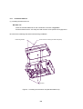
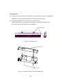
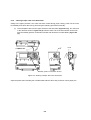
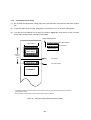
1
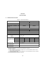
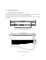
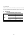
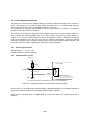
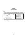
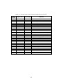
LTP F SERIES LINE THERMAL PRINTER MECHANISM TECHNICAL REFERENCE U00060419201 Seiko Instruments Inc. LTP F SERIES LINE THERMAL PRINTER MECHANISM TECHNICAL REFERENCE Document Number U00060419201 First Edition Second Edition August 2001 February 2002 Copyright © 2001, 2002 by Seiko Instruments Inc. All rights reserved. Seiko Instruments Inc. (SII) has prepared this manual for use by SII personnel, licensees, and customers. The information contained herein is the property of SII and shall not be reproduced in whole or in part without the prior written approval of SII. SII reserves the right to make changes without notice to the specifications and materials contained herein and shall not be responsible for any damages (including consequential) caused by reliance on the materials presented, including but not limited to typographical, arithmetic, or listing errors. SII is a trademark of Seiko Instruments Inc. PREFACE This reference manual describes the specifications and basic operating procedures for the LTP F Series Thermal Printer Mechanism (hereinafter referred to as “printer”). The LTP F series has the following two types of printers that are classified by their paper width. LTPF247A-C432 LTPF347A-C576 This manual usually describes information common to any printer, and each information with the name if information is different. Chapter 1 “Precautions” describes safety, design and operational precautions. Read it thoroughly before designing so that you are able to use the product properly. SII has not investigated the intellectual property rights of the sample circuits included in this manual. Fully investigate the intellectual property rights of these circuits before using. In particular, SII reserves the industrial property rights for the Heat Storage Simulation described in Chapter 3. Using it for the other printer is infringement on the industrial property rights. iii iv TABLE OF CONTENTS Section Page CHAPTER 1 PRECAUTIONS 1.1 1.2 SAFETY PRECAUTIONS ..................................................................................................... 1-1 DESIGN AND HANDLING PRECAUTIONS ......................................................................... 1-2 1.2.1 Design Precautions .................................................................................................. 1-2 1.2.2 Handling Precautions ............................................................................................... 1-5 1.2.3 Precautions on Discarding ....................................................................................... 1-6 CHAPTER 2 FEATURES CHAPTER 3 SPECIFICATIONS 3.1 3.2 3.3 3.4 3.5 3.6 GENERAL SPECIFICATIONS .............................................................................................. 3-1 HEAT ELEMENT DIMENSIONS ........................................................................................... 3-3 3.2.1 Heat Element Dimensions for the LTPF247............................................................. 3-3 3.2.2 Heat Element Dimensions for the LTPF347............................................................. 3-4 PAPER FEED CHARACTERISTICS..................................................................................... 3-5 STEP MOTOR CHARACTERISTICS ................................................................................... 3-6 3.4.1 Motor Drive Circuit.................................................................................................... 3-7 3.4.2 Motor Timing ............................................................................................................ 3-9 3.4.3 Motor Driving Precautions ...................................................................................... 3-10 THERMAL HEAD ................................................................................................................ 3-14 3.5.1 Structure of the Thermal Head (LTPF247)............................................................. 3-15 3.5.2 Printed Position of the Data (LTPF247) ................................................................. 3-16 3.5.3 Thermal Head Electrical Characteristics (LTPF247).............................................. 3-17 3.5.4 Structure of the Thermal Head (LTPF347)............................................................. 3-18 3.5.5 Printed Position of the Data (LTPF347) ................................................................. 3-19 3.5.6 Thermal Head Electrical Characteristics (LTPF347).............................................. 3-20 3.5.7 Timing Chart........................................................................................................... 3-21 3.5.8 Head Resistance .................................................................................................... 3-21 3.5.9 Head Voltage.......................................................................................................... 3-22 3.5.10 Peak Current .......................................................................................................... 3-22 CONTROLLING THE HEAD ACTIVATION (DST) PULSE WIDTH.................................... 3-23 3.6.1 Calculation of the Head Activation Pulse Width ..................................................... 3-23 3.6.2 Calculation of the Applied Energy .......................................................................... 3-23 3.6.3 Adjustment of the Head Resistance....................................................................... 3-24 3.6.4 Head Activation Pulse Term Coefficient................................................................. 3-24 3.6.5 Heat Storage Coefficient ........................................................................................ 3-25 3.6.6 Thermistor Resistance ........................................................................................... 3-26 3.6.7 Detecting Abnormal Temperatures of the Thermal Head ...................................... 3-28 v Section 3.7 3.8 Page PAPER DETECTOR ........................................................................................................... 3-29 3.7.1 General Specifications ........................................................................................... 3-29 3.7.2 Sample External Circuit.......................................................................................... 3-30 PLATEN POSITION DETECTOR ....................................................................................... 3-31 3.8.1 General Specifications ........................................................................................... 3-31 3.8.2 Sample External Circuit.......................................................................................... 3-31 CHAPTER 4 CONNECTING TERMINALS 4.1 4.2 THERMAL HEAD CONTROL TERMINALS .......................................................................... 4-2 MOTOR CONTROL TERMINALS......................................................................................... 4-5 CHAPTER 5 DRIVE METHOD CHAPTER 6 HOUSING DESIGN GUIDE 6.1 6.2 6.3 6.4 6.5 6.6 SECURING THE PRINTER .................................................................................................. 6-1 6.1.1 Printer Mounting Dimensions ................................................................................... 6-1 6.1.2 Recommended Screws ............................................................................................ 6-3 6.1.3 Precautions for Securing the Printer ........................................................................ 6-3 LAYOUT OF PRINTER AND PAPER ................................................................................... 6-4 WHERE TO MOUNT THE PAPER HOLDER ....................................................................... 6-5 WHERE TO MOUNT THE PLATEN UNIT............................................................................ 6-5 WHERE TO MOUNT THE PLATEN RELEASE KNOB ........................................................ 6-6 WHERE TO MOUNT THE PAPER CUTTER ....................................................................... 6-6 CHAPTER 7 APPEARANCE AND DIMENSIONS CHAPTER 8 LOADING/UNLOADING PAPER AND HEAD CLEANING 8.1 8.2 LOADING/UNLOADING PAPER PRECAUTIONS................................................................ 8-1 HEAD CLEANING PRECAUTIONS AND PROCEDURE ..................................................... 8-4 8.2 1 Head Cleaning Precautions...................................................................................... 8-4 8.2.2 Head Cleaning Procedure ........................................................................................ 8-4 vi Section Page CHAPTER 9 PERIPHERALS 9.1 AUTOCUTTER UNIT ............................................................................................................ 9-1 9.1.1 Installation Method ................................................................................................... 9-2 9.1.2 Clearing a Paper Jam in the Autocutter ................................................................... 9-4 9.1.3 Consideration for Outer Case Design ...................................................................... 9-5 9.1.4 Considerations for Using .......................................................................................... 9-7 9.1.5 Appearance of the Printer with the Autocutter Installed ........................................... 9-8 vii FIGURES Figure Page 3-1 3-2 3-3 3-4 3-5 3-6 3-7 3-8 3-9 3-10 3-11 3-12 3-13 3-14 3-15 3-16 Heat Element Dimensions (LTPF247) .................................................................................. 3-3 Print Area (LTPF247) ............................................................................................................ 3-3 Heat Element Dimensions (LTPF347) .................................................................................. 3-4 Print Area (LTPF347) ............................................................................................................ 3-4 Sample Drive Circuit.............................................................................................................. 3-7 Input Voltage Signals for the Sample Drive Circuit .............................................................. 3-8 Motor Start/Stop Timing ........................................................................................................ 3-9 Sample of Motor Current Control ........................................................................................ 3-13 Thermal Head Block Diagram (LTPF247)........................................................................... 3-15 Printed Position of the Data (LTPF247) .............................................................................. 3-16 Thermal Head Block Diagram (LTPF347)........................................................................... 3-18 Printed Position of the Data (LTPF347) .............................................................................. 3-19 Timing Chart........................................................................................................................ 3-21 Thermistor Resistance vs. Temperature ............................................................................. 3-26 Sample External Circuit of the Paper Detector.................................................................... 3-30 Sample External Circuit of the Platen Position Detector ..................................................... 3-31 4-1 4-2 Thermal Head Control Terminals .......................................................................................... 4-2 Terminals on the Motor Connector........................................................................................ 4-5 5-1 Timing Chart for Driving Using Two Divisions ....................................................................... 5-2 6-1 6-2 6-3 Printer Mounting Dimensions ................................................................................................ 6-2 Layout of Printer and Paper................................................................................................... 6-4 The Platen Unit Mounting Position ........................................................................................ 6-5 7-1 7-2 7-3 7-4 Appearance and Dimensions (LTPF247) .............................................................................. 7-2 Appearance and Dimensions of the Platen Unit(LTPF247) .................................................. 7-3 Appearance and Dimensions (LTPF347) .............................................................................. 7-4 Appearance and Dimensions of the Platen Unit (LTPF347) ................................................. 7-5 8-1 8-2 8-3 8-4 Loading Paper (1).................................................................................................................. 8-1 Loading Paper (2).................................................................................................................. 8-2 Loading Paper (3).................................................................................................................. 8-2 Head Cleaning Procedure ..................................................................................................... 8-4 9-1 9-2 9-3 9-4 9-5 9-6 9-7 9-8 9-9 9-10 9-11 Installing the Autocutter Unit (Movable blade unit) ................................................................ 9-2 Fixing Blade Unit ................................................................................................................... 9-3 Installing Autocutter Unit (Fixing blade unit) .......................................................................... 9-3 Clearing a Paper Jam in the Autocutter ................................................................................ 9-4 Outer Case Design................................................................................................................ 9-5 Outer Case Design sample (Mechanism Side) ..................................................................... 9-6 Using the Paper Effectively When Cutting ............................................................................ 9-7 Appearance of the Printer with the Autocutter Installed (LTPF247 with ACUF224A) ........... 9-8 Appearance of the Printer with the Autocutter Installed (LTPF247 with ACUF224B) ........... 9-9 Appearance of the Printer with the Autocutter Installed (LTPF347 with ACUF324A) ......... 9-10 Appearance of the Printer with the Autocutter Installed (LTPF347 with ACUF324B) ......... 9-11 viii TABLES Table Page 3-1 3-2 3-3 3-4 3-5 3-6 3-7 3-8 3-9 3-10 3-11 3-12 3-13 3-14 General Specifications .......................................................................................................... 3-1 General Motor Specifications ................................................................................................ 3-6 Excitation Sequence.............................................................................................................. 3-8 Acceleration Steps............................................................................................................... 3-11 Motor Current Value ............................................................................................................ 3-12 DST Blocks and Activated Heat Elements (LTPF247)........................................................ 3-16 Thermal Head Electrical Characteristics (LTPF247)........................................................... 3-17 DST Blocks and Activated Heat Elements (LTPF347)........................................................ 3-19 Thermal Head Electrical Characteristics (LTPF347)........................................................... 3-20 Head Resistance Ranks...................................................................................................... 3-21 Head Voltage....................................................................................................................... 3-22 Temperature and Corresponding Thermistor Resistance................................................... 3-27 Absolute Maximum Ratings of the Paper Detector (at 25 °C)............................................. 3-29 Paper Detector Input/Output Conditions ............................................................................. 3-30 4-1 4-2 4-3 4-4 Connectors for External Circuit and Recommended Connectors for the Other FFC ............ 4-1 Thermal Head Control Terminal Assignments (LTPF247).................................................... 4-3 Thermal Head Control Terminal Assignments (LTPF347).................................................... 4-4 Motor Control Terminal Assignments .................................................................................... 4-5 9-1 Printer Mechanism and Corresponding Autocutter Unit ........................................................ 9-1 ix x CHAPTER 1 PRECAUTIONS Read through this manual to design and operate the printer properly. Pay special attention to the precautions noted in each section. 1.1 SAFETY PRECAUTIONS Follow these precautions when designing a product using the printer, and include any necessary precautions and warning labels to ensure the safe operation of your product by users. z Preventing the thermal head from overheating When electricity is continuously supplied to the thermal head heat element by a CPU or other malfunction, the thermal head may overheat, causing smoke and fire. Follow the method described in Section 3.6.7 to monitor the temperature of the thermal head to prevent overheating. Turn the printer off immediately if any abnormal conditions occur. z Preventing the user from touching the thermal head and motor Warn the user not to touch the thermal head, its periphery or motor as they are hot during and immediately after printing. Failure to follow this instruction may lead to personal injury including burns. Also, allow cooling by designing clearance between the head, motor and the outer case. z Precautions for sharp edges of the printer body Design the outer case so that the user cannot touch sharp edges of the printer body or the cutting surface of metal parts. Or, provide warnings concerning this matter. 1-1 1.2 DESIGN AND HANDLING PRECAUTIONS To maintain the initial level of performance of the printer and to prevent future problems from occurring, observe the following precautions. 1.2.1 Design Precautions Design precautions z If too much energy is applied to the thermal head, it may overheat and become damaged. Always use the printer with the specified amount of energy. z The current capacity of the thermal head is 13.6A. Design the circuit so that the average current does not exceed this value. (However, when the current capacity standard of harness is MAX.1A/pin, since the numbers of VP and GND pins are 8 pins and 9 pins, respectively, the current will be 8A and 9A each. z Use C-MOS IC chips (74HC240 or equivalent) for interfacing the CLK, LATCH, DAT and DST signals of the thermal head. z When turning the power on or off, always DISABLE (put in “high” state) the DST terminals. z To prevent the thermal head from being damaged by static electricity: • • Fix the printer to the Frame Ground (FG) by FG connection portions shown in Figure 7-1 to Figure 7-3. Connect the GND terminal (SG) to FG through an approximately 1 MΩ resistor. z Keep the Vp power off while not printing in order to prevent the thermal head from being electrically corroded. In addition, design the printer so that the signal GND of the thermal head and the frame GND of the printer mechanism become the same electric potential. z Wire resistance should be 50 mΩ or less and 30 cm or less (however the less the better) between the power supply and the Vp, and the GND terminals on the thermal head controller. Maintain a considerable distance from signal lines to reduce electrical interference. z A surge voltage between Vp and GND should not exceed 28 V. z As a noise countermeasure, connect the capacitor noted below between the Vdd and GND terminals near the thermal head control connector. Capacitor: 0.1 µF/15 V (aluminum electrolytic) z Always detect the outputs of the platen position and paper detectors. Incorrect activation of the thermal head may reduce the life of the thermal head and the platen and damage them. z The head activation time period may become longer according to the printing condition. If so, hold the phase of the motor and keep the pause time of the head activation for 0.1 msec or more. A continuous printing without a pause time may damage the thermal head. 1-2 z Always close the platen and feed the paper at 16 dots or more per line when printing is in a standby state. The elastic deformation of the platen roller rubber will be retreated. Mechanism precautions z Apply power in the following manner: When turning the power ON: 1) Vdd (5 V) At shut down: 1) Vp (24 V) → → 2) Vp (24 V) 2) Vdd (5 V) z Cut surfaces of metallic parts may become discolored and rusted due to the operational environment. Consider these factors regarding appearance. z Do not apply any stress to the thermal head connector when inserting and removing the PCB (Printed Circuit Board). After the PCB has been connected to the thermal head connector, design the outer case so that stress does not apply to the head connector. Stress may cause printing problems, resulting in damage to the thermal head. z Always release the pressure of the thermal head when not using the printer for a long time (put the platen in platen open state). The platen pressured to the thermal head may become deformed. z When closing the platen unit, the gear of the platen driving wheel may come in contact with the gear of the reduction wheel, making it impossible to install the platen. In this case, open the platen, and then close it again. z Handle the platen unit with care because it is detachable. Flaws or dust on the platen roller and the platen driving wheel may reduce print quality. Be careful during installation because the plate may become deformed by stress. z Do not pull out paper when the platen unit is closed. z Stress to the platen frame while printing may reduce print quality. 1-3 Printing and paper feeding precautions z Make sure that variation in the motor drive frequency does not lead to noise or a loss of paper feed force before making designs. z Design the outer case to prevent the paper feed out from being caught in the platen. z When or after printing or paper feed has been suspended, if data is input or printing restarts, paper feed may not be performed properly for several dot lines just after printing starts. This problem is more likely to occur when printing bit images. z Do not open the platen unit while printing. The printer may be damaged. z Do not use label paper, carbon paper, and thermal paper of more than 80µm. z Do not perform back feed (backspin of the motor). 1-4 1.2.2 Handling Precautions Incorrect handling may reduce the efficiency of the printer and cause damage. Handle the printer with the following precautions. Also, include any necessary precautions so that users handle the printer with care. z To prevent the heat elements, ICs, etc. from static electricity, discharge all static electricity before handling the printer. Pay special attention to the thermal head control terminals when handling. z Do not apply stress to the thermal head control terminals: Doing so may damage the connectors. z If any paper other than that specified is used, high print quality and long life of the thermal head cannot be guaranteed. z Using anything other than the specified paper may cause the following: Poor printing quality Abrasion of the thermal head The thermal surface of the paper and the thermal head may stick together Excessive noise Fading print Corroded thermal head z Always print or feed with the specified paper inserted to protect the platen and thermal head. z Do not hit or scratch the surface of the thermal head with any sharp or hard objects as it may damage the heat element. z When the printer is not in use, place the thermal head in up position. The head down (platen “close” state) and head up (platen “open” state) positions can be set with head up/down lever. If the thermal head is remained in contact with the platen, the platen may become deformed. z Never connect or disconnect cables with the power on. Always power off the printer first. z When printing a black or checkered pattern at a high print rate in a low temperature or high humidity environment, the vapor from the paper during printing may cause condensation to form on the printer or may soil the paper. If water condenses on the printer, keep the thermal head away from water drops as it may corrode the thermal head, and turn Vp off until it dries. z The printer is not water-proof. Prevent contact with water and do not operate with wet hands as it may damage the printer or cause a short circuit or fire. z Never use the printer in a dusty place, as it may damage the thermal head and cause paper feed trouble. 1-5 1.2.3 Precautions on Discarding When discarding used printers, discard them according to the disposal regulations and rules of each respective district. 1-6 CHAPTER 2 FEATURES The LTP F Series Line Thermal Printer Mechanism is a compact, super high-speed thermal line dot printing mechanism. It can be used with a measuring instrument and analyzer, a POS, a communication device, or a data terminal device. The LTP F Series has the following features: z Super high speed printing ∗1 A maximum print speed of 1760 dot lines per second (220 mm per second) is attainable for the LTP F series printer mechanism. z Easy loading of printing paper An easy loading of a printing paper with a detachable platen unit. z High resolution printing A high-density print head of 8 dots/mm produces clear and precise printing. z Long life ∗2 The mechanism is maintenance-free device with a long life of 100 km print length or 100 million pulses. z Low noise Thermal line dot printing is used to guarantee low-noise printing. z Thermal head cleaning The removable platen unit enables the thermal head of the printer to be cleaned easily. z Anti-static electricity function Exposed metal parts of the printer can be connected to Frame Ground (FG) to minimize secondary radiation. ∗1 ∗2 Print speed differs depending on working conditions. Based on the life span judgment in the general specifications. 2-1 2-2 CHAPTER 3 SPECIFICATIONS 3.1 GENERAL SPECIFICATIONS Table 3-1 General Specifications Item Print method Dots per line Printable dots per line Simultaneously activatable dots per line Resolution Maximum print speed ∗1 Print width Paper width Paper feed pitch Head temperature detection Platen position detection Out-of-paper detection Operating voltage range Vp line Vdd line ∗3 Current Print ratio consumption used 100% in driving the head 50% (Vp) ∗2 25% 12.5% Motor drive (Vp) Head Logic (Vdd) Operating temperature range (No condensation) Storage temperature range (No condensation) ∗1 ∗2 ∗3 Specification LTPF247 Thermal dot line printing 448 dots 432 dots 248 dots LTPF347 640 dots 576 dots 352 dots 8 dots/mm 220 mm/sec 54 mm 58 mm 0.125 mm Via a thermistor Via a mechanical switch Via a photo interrupter 24V ± 10% 5V ± 5% Max. 10.4A 5.2A 2.6A 1.3A 0.55 A max. 0.1 A max. 0°C to 50°C Rated 9.2A 4.6A 2.3A 1.2A 72 mm 80 mm Max. 14.8A 7.4A 3.7A 1.9A Rated 13.0A 6.5A 3.3A 1.7A -20°C to 60°C Print speed changes according to the processing speed of the controller and print pulse width. The current value indicates a momentary value obtained by calculation. Calculation conditions (1) “Max.” indicates the values when the voltage is 26.4 V, the head resistance is 630.5 Ω, and fixed two-division printing is used. (2) “Rated” indicates the values when the voltage is 24 V, the head resistance is 650 Ω, and fixed two-division printing is used. When printing equal to the print width is performed. 3-1 Table 3-1 General Specifications (Continued) Item Life span (at 25°C and rated energy) Activation pulse resistance Abrasion resistance Paper feed force Paper hold force Dimensions (excluding the lever and convex part) (width × depth × height) Mass Specified thermal paper ∗4 Specification LTPF247 LTPF347 100 million pulses or more ∗4 100 km or more (excluding damage caused by dust and foreign materials) 0.98N (100 gf) or more 0.98N (100 gf) or more 86.2 × 54 × 25.8 mm 110.2 × 54 × 25.8 mm Approx. 150g TF50KS-E2C Normal thermal paper PD160R-N Medium proof paper HP220AB1 Medium proof paper Changing rate of average head resistance: ±15% or less 3-2 Approx. 175g Nippon Paper Industries Oji Paper Co., Ltd. MITSUBISHI PAPER MILLS LIMITED 3.2 3.2.1 HEAT ELEMENT DIMENSIONS Heat Element Dimensions for the LTPF247 The LTPF247 contains a thermal head with 448 heat elements (dot-size). The 432 dots (54 mm to the paper width 58 mm) is a printable area due to a relation with the paper width. When transmitting print data, enter (NUL) data for data strings equivalent to 8 dots each on the right and left sides. 448 Dots (56mm) 8 Dots 432 Dots (54mm) 8 Dots 0.125 mm Printable area Figure 3-1 Heat Element Dimensions (LTPF247) 58 2 mm +0 -1 mm (Paper width) 54 mm (Printing width) 2 mm 0.125 mm (Paper feed pitch) Figure 3-2 Print Area (LTPF247) 3-3 3.2.2 Heat Element Dimensions for the LTPF347 The LTPF347 contains a thermal head with 640 heat elements (dot-size). The 576 dots (72 mm to the paper width 80 mm) is a printable area due to a relation with the paper width. When transmitting print data, enter (NUL) data for the data string equivalent to 32 dots each in right and left sides. 640 Dots (80mm) 32 Dots 576 Dots (72mm) 32 Dots 0.125mm Printable area Figure 3-3 Heat Element Dimensions (LTPF347) 80 3 mm +0 mm (Paper width) -1 74 mm (Printing width) 3 mm 0.125 mm (Paper feed pitch) Figure 3-4 Print Area (LTPF347) 3-4 3.3 PAPER FEED CHARACTERISTICS z The bipolar chopper driving method should be used for driving. z Any type of design for the drive circuit other than the example described in Section 3.4.1 may affect the standard function of the printer. z Paper is fed in the forward direction when the motor shaft is rotating anticlockwise as seen from the motor gear side. z The motor is driven by a 2-2 phase excitation method and feeds paper by 0.125 mm (equivalent to a single dot pitch) every one step of the motor drive signal. z To prevent deterioration in print quality due to backlash of the paper feed system, the motor should be rotated 16 steps in the reverse direction, then 16 steps in the normal direction during initialization. z During paper feed, the motor should be driven at 1760 pps through the motor acceleration control. As exceptions, when using the LTPF347 under 0°C to 10°C in temperature, drive it at 1200 pps or less. At dynamic division driving, do not use it more than 1200 pps. z During printing, the motor drive frequency should be adjusted so that the head activation pulse width does not exceed the motor step time. (For details, see CHAPTER 5 DRIVE METHOD.) z If the motor is continuously driven at less than 450 pps continuously, noise and/or paper sticking may occur. 3-5 3.4 STEP MOTOR CHARACTERISTICS Table 3-2 General Motor Specifications Item Specification Type Drive method Excitation Winding resistance per phase Rated voltage Set current PM Bipolar chopper 2-2 phase 16Ω/phase±10% Vp: 24 V±10% Approximately 275 mA/phase 3-6 3.4.1 Motor Drive Circuit (1) Sample Drive Circuit A sample drive circuit for the motor is shown in Figure 3-5. Rated voltage Vp: 24±10% Vcc: 5±5% Recommended motor driver Shin Kaden Kogyo MTD2007F Figure 3-5 Sample Drive Circuit 3-7 Excitation Sequence PH1 PH2 Step 4 Step 3 Step 2 Step 1 Step 4 Step 3 Step 2 When the voltage signals shown in Figure 3-6 are input to the motor drive circuit shown in Figure 3-5, as shown in Table 3-3, the LTP F Series feeds the paper in the normal direction when the motor is excited in the order of step 1, step 2, step 3, step 4, step 1, step 2, . . . . Step 1 (2) H L H L 1 dot line Figure 3-6 Input Voltage Signals for the Sample Drive Circuit Table 3-3 Excitation Sequence Input Signal Output Signal PH1 PH2 B A B A Step 1 L L L L H H Step 2 H L L H H L Step 3 H H H H L L Step 4 L H H L L H 3-8 3.4.2 Motor Timing Refer to the time chart in Figure 3-7 when designing the control circuit or software for starting and stopping the motor. Also, note the following precautions: Precautions for Designing the Motor Control Circuit and Software (1) Stop step z To stop the motor, excite for 10 msec with the same phase as the last one in the printing step. (2) Pause state z In the pause state, do not excite the step motor by having I0, I1 go high so as to prevent the motor from heating. Even when the step motor is not excited, it maintains force to prevent the paper from sliding by a torque operation. (3) Start step z To restart the motor from the stop step, immediately shift the motor into the print sequence. z To restart the motor from the pause (no excitation) state, shift the motor into the print step sequence after outputting the same phase as that of the stop step for the first step time of the acceleration step. Input signals for a sample drive circuit are shown in Figure 3-7. PH1 H L PH2 H L H I0,I1 L Print step Pause step Pause standby Figure 3-7 Motor Start/Stop Timing 3-9 Start step Print step 3.4.3 Motor Driving Precautions Acceleration Control When driving the motor, acceleration control is needed to get start up in order to maintain the power force. Drive the motor to the driving speed, according to acceleration steps shown in Table 3-4. The method for accelerating the motor is as follows: 1. 2. 3. 4. 5. Output the start step time. Output the first step for the first acceleration step time Output the second step for the second acceleration step time Output the nth step for the nth step acceleration time After accelerating up to the motor driving speed, the motor is driven at constant speed. The printer can print during acceleration. The maximum printing speeds differ depending upon the drive method of the thermal head. Set the acceleration step as follows. Accelerate the motor up to the step number 126 and motor driving frequency 1760 (PPS) for performing an acceleration control at two-division driving. At dynamic division driving, or, when using the LTPF347 under 0°C to 10°C in temperature, change step number 59 into the motor driving frequency of 1200 (PPS) and step time 833 (µSEC), and then accelerate the motor up to the step number 59 and motor driving frequency 1200 (PPS). 3-10 Table 3-4 Acceleration Steps Number of Steps Speed (pps) Step Time (µsec) Number of Steps Speed (pps) Step Time (µsec) Number of Steps Speed (pps) Step Time (µsec) Start 1 2 3 4 5 6 7 8 9 10 11 12 13 14 15 16 17 18 19 20 21 22 23 24 25 26 27 28 29 30 31 32 33 34 35 36 37 38 39 40 41 42 --111 179 232 383 400 412 440 466 491 515 538 560 581 601 621 640 659 677 695 712 729 745 761 777 793 808 823 837 852 866 880 894 907 921 934 947 959 972 985 997 1009 1021 9027 9027 5579 4308 2614 2500 2426 2272 2144 2035 1941 1859 1786 1721 1663 1610 1561 1517 1477 1439 1404 1372 1342 1313 1287 1261 1238 1215 1194 1174 1155 1136 1119 1102 1086 1071 1056 1042 1029 1016 1003 991 979 43 44 45 46 47 48 49 50 51 52 53 54 55 56 57 58 59 60 61 62 63 64 65 66 67 68 69 70 71 72 73 74 75 76 77 78 79 80 81 82 83 84 85 1033 1045 1056 1068 1079 1090 1102 1113 1124 1134 1145 1156 1166 1177 1187 1197 1207 1217 1227 1237 1247 1257 1267 1276 1286 1295 1305 1314 1323 1333 1342 1351 1360 1369 1378 1387 1395 1404 1413 1421 1430 1438 1447 968 957 947 936 927 917 908 899 890 882 873 865 857 850 842 835 828 821 815 808 802 796 789 784 778 772 766 761 756 750 745 740 735 731 726 721 717 712 708 704 699 695 691 86 87 88 89 90 91 92 93 94 95 96 97 98 99 100 101 102 103 104 105 106 107 108 109 110 111 112 113 114 115 116 117 118 119 120 121 122 123 124 125 126 1455 1464 1472 1480 1489 1497 1505 1513 1521 1529 1537 1545 1553 1561 1569 1577 1584 1592 1600 1607 1615 1622 1630 1637 1645 1652 1660 1667 1674 1682 1689 1696 1703 1711 1718 1725 1732 1739 1746 1753 1760 687 683 679 675 672 668 664 661 657 654 651 647 644 641 637 634 631 628 625 622 619 616 614 611 608 605 603 600 597 595 592 590 587 585 582 580 577 575 573 570 568 3-11 Motor Current Control The motor driving at a low speed may make noises during motor driving. Change the current value supplied to the motor so that the noise can be reduced. The current value supplied can be switched by controlling I0 and I1 as follows. Table 3-5 Motor Current Value Motor reference set current Im = Approx. 275 mA I0 I1 LOW LOW HIGH LOW LOW HIGH HIGH HIGH Current Value Im 7 10 4 10 0 10 (Approx. 275mA) Im Im Im 0mA In each motor driving step, when the motor step time Tm (ms) is over 2.5 ms, drive the motor 4/10Im up to the time of Tm-2.5 (ms) and switch it into Im (approx. 275mA). Drive the motor at Im (approx. 275 mA) if the motor step time Tm (ms) is 2.5 ms or less. It is not required to switch the current. When the previous motor step time is 2.5 ms or less, drive the motor at Im (approx. 275 mA). Do not switch the current even when the motor step time Tm (ms) is more than 2.5 ms. 3-12 A sample motor current control is shown in Figure 3-8. Less More than More than than More than More than 2.5ms 2.5ms 2.5ms 2.5ms 2.5ms Motor drive current Approx. 275 275mA) 4 10 0 10 Figure 3-8 Sample of Motor Current Control Drive the motor at Im (approx. 275 mA) during the start-up step and the stop step. Do not switch the current. Continuous driving When the motor is driven for a long time or motor drive is often performed repeatedly, the motor heats up and may not be able to show necessary performance. To avoid it, when the motor was driven, set up the pause time of the same period of time as that the motor was driven. Furthermore, make onetime continuous driving 6 minutes (max.). 3-13 3.5 THERMAL HEAD The thermal head consists of heat elements and a head driver which drives and controls the heat element. Serial print data input from the DAT IN terminal is transferred to the shift register synchronously with the CLK signal, then stored in the latch register at the timing of the LATCH signal. Input of the head print activation signal (DST1, 2) activates the heat elements in accordance with the print data stored in the latch register. The LTP F series can be printed by dividing printing into blocks for every 128 dots. The divided printing is effective for a high print ratio printing because the peak current can be cut down with the reduction of the average print speed. When printing is performed using division into blocks of less than 128 dots, messy printing and/or abnormal sound may occur, and the printing quality may deteriorate remarkably. Check the number of dots in advance. Also, when a pattern with a high print ratio is printed with less than 176 dots, a printing failure may occur due to the printing paper getting stuck depending on the ambient temperature, drive voltage and the thermal paper that is used. When using a high-print ratio pattern, check the number of dots in advance. 3-14 3.5.1 Structure of the Thermal Head (LTPF247) Figure 3-9 shows the thermal head block diagram for the LTPF247. Table 3-7 shows the relationship between DST blocks and activated heat elements. DOT1 DOT192 DOT193 Block 1 DOT448 Block 2 Vp Heat elements Output driver Latch register Shift register DAT IN2 CLK LATCH DST2 DAT OUT2 *1 DAT IN1 DST1 DAT OUT1 *1 TH Thermistor TH Vdd GND *1 N.C. if not using DAT OUT Figure 3-9 Thermal Head Block Diagram (LTPF247) 3-15 Table 3-6 DST Blocks and Activated Heat Elements (LTPF247) 3.5.2 DST Number Heat Element Number Dots/DST DST 1 DST 2 1 to 192 193 to 448 192 256 Printed Position of the Data (LTPF247) 192 data dots from No.1 to No.192 which are transferred through DAT IN1 terminal and 256 data dots from No.193 to No.448 are printed as shown in Figure 3-10. For No.1 to No.8 of 192 data dots transferred from the DATA IN1 and No.441 to No.448 of 256 dots data transferred from the DATA IN2, set the NULL data. Paper Paper feed direction Print surface Data print sequence Data in 1 2 3 4 5 6 ................... 446 447 448 LTPF247 printer mechanism DATA IN1 Data input sequence 1 2 . . . . . . 191 192 DATA IN2 Data input sequence 193 194 . . . . . . 447 448 Figure 3-10 Printed Position of the Data (LTPF247) 3-16 3.5.3 Thermal Head Electrical Characteristics (LTPF247) Table 3-7 Thermal Head Electrical Characteristics (LTPF247) (Ta=25 ± 10°C) Item Head resistance Head drive voltage Head drive current Symbol RH Vp Ip Logic block voltage Vdd Logic block current Idd "High" VIH Input voltage "Low" VIL "High" IIH DAT DAT input current "Low" IIL DAT "High" IIH DST DST input current "Low" IIL DST "High" IIH CLK CLK input current "Low" IIL CLK IIH LAT LATCH input "High" current "Low" IIL LAT "High" VDOH DAT output current "Low" VDOL CLK frequency f CLK CLK pulse width tw CLK DAT setup-time tsetup DI DAT hold time thold DI DAT out delay time td DO LATCH pulse width tw LAT LATCH setup time tsetup LAT LATCH hold time thold LAT DST setup time tsetup DST Output delay time tDo Conditions At max. simultaneously activated dots number=248 Rated value TYP MAX 630.5 21.6 − 650 24.0 9.2 669.5 26.4 10.4 Ω V A 5.00 − − − − − − − − − − − − − − − − − − − − − − − 5.25 64 Vdd 0.2×Vdd 0.5 −0.5 120 −2.0 2.0 −2.0 2.0 −2.0 − 0.05 4 − − − 120 − − − − 10 V mA V V µA µA µA µA µA µA µA µA µA µA MHz ns ns ns ns ns ns ns ns ns 4.75 fCLK=8MHz,fDI=1/2fCLK − CLK,DAT,LATCH,DST 0.8×Vdd CLK,DAT,LATCH,DST 0 VIH = 5V − VIL = 0V − − − − − − − OPEN state, Vdd =4.5V 4.45 − − See Timing Chart 35 See Timing Chart 30 See Timing Chart 10 See Timing Chart − See Timing Chart 100 See Timing Chart 200 See Timing Chart 50 See Timing Chart 300 See Timing Chart − 3-17 Unit MIN 3.5.4 Structure of the Thermal Head (LTPF347) Figure 3-11 shows the thermal head block diagram for the LTPF347. Table 3-8 shows the relationship between DST blocks and activated heat elements. DOT1 DOT384 Block 1 DOT385 DOT640 Block 2 Vp Heat elements Output driver Latch register Shift register DAT IN2 CLK LATCH DST2 DAT OUT2 *1 DAT IN1 DST1 DAT OUT1 *1 Thermistor TH TH Vdd GND *1 N.C. if not using DAT OUT Figure 3-11 Thermal Head Block Diagram (LTPF347) 3-18 Table 3-8 DST Blocks and Activated Heat Elements (LTPF347) 3.5.5 DST Number Heat Element Number Dots/DST DST1 DST2 1 to 384 385 to 640 384 256 Printed Position of the Data (LTPF347) 384 data dots from No.1 to No.384 which are transferred through DAT IN1 terminal and 256 data dots from No.385 to No.640 are printed as shown in Figure 3-12. For No.1 to No.32 of 384 data dots transferred from the DATA IN1 and No.609 to No.640 of 256 data dots transferred from the DATA IN2, set the NULL data. Paper feed direction Paper Print surface Data in Data print sequence 1 2 3 4 5 6 .................... 638 639 640 LTPF347 printer mechanism DATA IN1 Data input sequence DATA IN2 Data input sequence 1 2 . . . . . . 383 384 385 386 . . . . . . 639 640 Figure 3-12 Printed Position of the Data (LTPF347) 3-19 3.5.6 Thermal Head Electrical Characteristics (LTPF347) Table 3-9 Thermal Head Electrical Characteristics (LTPF347) (Ta=25 ± 10°C) Item Head resistance Head drive voltage Head drive current Symbol RH Vp Ip Logic block voltage Vdd Logic block current Idd "High" VIH Input voltage "Low" VIL "High" IIH DAT DAT input current "Low" IIL DAT "High" IIH DST DST input current "Low" IIL DST "High" IIH CLK CLK input current "Low" IIL CLK IIH LAT LATCH input "High" current "Low" IIL LAT "High" VDOH DAT output current "Low" VDOL CLK frequency f CLK CLK pulse width tw CLK DAT setup-time tsetup DI DAT hold time thold DI DAT out delay time td DO LATCH pulse width tw LAT LATCH setup-time tsetup LAT LATCH hold time thold LAT DST setup time tsetup DST Output delay time tDo Conditions At max. simultaneously activated dots number=352 FCLK=8MHz,fDI=1/2fclk CLK,DAT,LATCH,DST CLK,DAT,LATCH,DST VIH = 5V VIL = 0V OPEN state, Vdd =4.5V See Timing Chart See Timing Chart See Timing Chart See Timing Chart See Timing Chart See Timing Chart See Timing Chart See Timing Chart See Timing Chart 3-20 Rated value Unit MIN TYP MAX 630.5 21.6 − 650 24.0 13.0 669.5 26.4 14.8 Ω V A 4.75 − 0.8×Vdd 0 − − − − − − − − 4.45 − − 35 30 10 − 100 200 50 300 − 5.00 − − − − − − − − − − − − − − − − − − − − − − − 5.25 64 Vdd 0.2×Vdd 0.5 −0.5 120 −2.0 2.0 −2.0 2.0 −2.0 − 0.05 8 − − − 120 − − − − 5 V mA V V µA µA µA µA µA µA µA µA µA µA MHz ns ns ns ns ns ns ns ns ns 3.5.7 Timing Chart tw CLK thold LAT CLK tsetup DI thold DI DAT IN td DO DAT OUT tsetup LAT LATCH tw LAT tsetup DST DST t Do DRIVE OUT Figure 3-13 Timing Chart 3.5.8 Head Resistance The LTP F Series head resistance is as shown in Table 3-10. Table 3-10 Head Resistance Ranks Head Resistance 630.5 to 669.5 Ω 3-21 t Do (Hi Active) 3.5.9 Head Voltage The printer has a built-in head driver IC. Table 3-11 shows the head voltage. Table 3-11 Head Voltage Item 3.5.10 Voltage Range Head drive voltage VP 21.6 to 26.4 V Head logic voltage Vdd 4.75 to 5.25 V Peak Current Since the peak current (maximum current) may reach the values calculated using equation (1) when the thermal head is driven, make sure that the allowable current for the cable material and the voltage drop on the cables are well within the specified range. Equation (1): IP= N × VP RH IP: N: VP: RH: Peak current (A) Number of dots that are driven at the same time Head drive voltage (V) Head resistance (Ω) 3-22 3.6 CONTROLLING THE HEAD ACTIVATION (DST) PULSE WIDTH 3.6.1 Calculation of the Head Activation Pulse Width To execute high quality printing using the printer, the value that is calculated using the following equation (2) must be adjusted according to the printer installation environment. Calculate each value used according to the steps in Sections 3.6.2 to 3.6.5 and control so that the pulse width with the t (msec) value obtained by substituting each value into the equation (2). Equation (2): t = E× t: V: E: R: C: D: R 2 ×C×D V Heat pulse width (ms) Applied voltage (V) Standard applied energy (mj) Head resistance (Ω) Head activation pulse term coefficient Heat Storage coefficient Refer to Section 3.6.2. Refer to Section 3.6.3. Refer to Section 3.6.4. Refer to Section 3.6.5. Printing using too high of voltage or too long of pulse width may shorten the life of the thermal head. 3.6.2 Calculation of the Applied Energy The applied energy should be according to the temperature of the thermal head and operational environment. The thermal head has a built-in thermistor. Measure the temperature using the thermistor resistance. The applied energy also differs according to the thermal paper used. The applied energy is calculated by substituting a temperature coefficient and thermal paper coefficient into the equation (3). Equation (3): E= E0 × P × (1−Tc (Tx−25)) E: E0: TX: P: Print energy (mj) Standard applied energy 0.210 (mj) 1 Detected temperature using the thermistor (°C) Thermal paper coefficient TF50KS-E2C (Nippon Paper Industries): PD160R-N (New Oji Paper Co., Ltd): HP220AB1 (MITSUBISHI PAPER MILLS LIMITED): TC: Temperature coefficient: ∗1 0.9 1.0 1.0 0.0076 The thermistor resistance value at TX (°C). Refer to Section 3.6.6. 3-23 3.6.3 Adjustment of the Head Resistance Adjustment of the head resistance is according to equation (4). Due to wiring resistance there is a drop in voltage. Equation (4): R= ( RH + Ri + (Rc + rc ) ×N )2 RH RH:Head resistance, RH=650 Ω Ri: Wiring resistance in the thermal head (Ω), Ri=25Ω RC: Common terminal wiring resistance in the thermal head LTPF247 RC=0.14 (Ω) LTPF347 RC=0.165 (Ω) rc: Wiring resistance between Vp and GND (Ω)∗1 N: Number of dots driven at the same time ∗1 3.6.4 This resistance value is equal to the resistance of the wire used between the thermal head control connector and the power supply including the resistance of switching circuit of relay, etc. Head Activation Pulse Term Coefficient According to equation (5), calculate the compensation coefficient of the head activation pulse term (equal motor drive frequency) to get the constant printing density even when changing the printing speed such as start up acceleration control. Equation (5): C=2.7 - 3.59 Cx + W Cx: Speed correction coefficient 1.57 W: Head activation cycle of one dot line (ms) ∗ When the motor drive frequency is 666 pps or less: W = 666 pps (fixed) 3-24 3.6.5 Heat Storage Coefficient A difference between an actual rise in temperature of the thermal head due to the head activation and the detected temperature by the thermistor occurs in the high speed printing. Therefore, a correction of the activation pulse through the simulation of a rise in thermal head temperature is needed. A correction may not be needed when the print ratio is low. Set “1” as the heat storage coefficient at this time. The heat storage coefficient is calculated with the manner as follows: (1) Prepare the heat storage software counters for each block to simulate the heat storage. (a) Heat storage due to the head activation The heat storage counter counts up in each print cycle as follows. D= 64×N B When D>50, D=50 T’=T+D T: Heat storage counter value N: Number of the activated dots B: Total dot number of each block (b) Radiation due to time The heat storage counter value is multiplied by the radiation coefficient in each 1 msec. T’=T×K K: Radiation coefficient 0.997 (2) Calculate the heat storage coefficient with the following equation, using the heat storage counter. Equation (6): D=1- T 74981 3-25 3.6.6 Thermistor Resistance The resistance of the thermistor at the operating temperature TX (°C) is determined using the following equation (7). Equation (7): RX=R25 × EXP 1 B× 273+TX RX: R25: B: TX: EXP (A) : 1 − 298 Resistance at operating temperature Tx (°C) 30 kΩ ± 5% (25°C) 3950 K ± 2 % Operating temperature (°C) The Ath power of natural logarithm e (2.71828) [Rating] Operating temperature range: -40 °C to +125 °C ’Resistance ï R ’li ‚‹ ƒ(kΩ) ¶j 100 10 1 0 10 20 30 40 50 60 ‰· “ x i Ž (°C) j Temperature 70 80 Figure 3-14 Thermistor Resistance vs. Temperature 3-26 90 100 Table 3-12 Temperature and Corresponding Thermistor Resistance Temperature (°°C) Thermistor Resistance (kΩ Ω) 0 5 10 15 20 25 30 35 40 45 50 55 60 65 70 75 80 85 90 95 100 100.99 77.85 60.57 47.53 37.61 30.00 24.11 19.51 15.89 13.03 10.75 8.92 7.45 6.25 5.27 4.47 3.80 3.25 2.79 2.41 2.09 3-27 3.6.7 Detecting Abnormal Temperatures of the Thermal Head To protect the thermal head and to ensure personal safety, abnormal thermal head temperatures must be detected by both hardware and software as follows: z Detecting abnormal temperatures by software Design software that will deactivate the heat elements if the thermal head thermistor (TH) detects a temperature of 80°C or more (thermistor resistance RTH ≤ 3.80 kΩ), and reactivate the heat elements when a temperature of 60°C or lower (RTH ≥ 7.45 kΩ) is detected. If the thermal head continues to be activated at a higher temperature than 80°C, the life of the thermal head may be shortened significantly. z Detecting abnormal temperatures by hardware If the control unit (CPU) malfunctions, the software for detecting abnormal temperatures may not function properly, resulting in overheating of the thermal head. The overheating of the thermal head may cause damage to the thermal head or cause skin burns. Always use hardware in conjunction with software for detecting abnormal temperatures to ensure personal safety (this may not prevent damage to the thermal head). Using a window comparator circuit or similar detector, design hardware that detects the following abnormal conditions: (a) Overheating of the thermal head (approximately 100°C or higher (RTH ≤ 2.09 kΩ)) (b) Faulty thermistor connection (the thermistor may be open or short-circuited). If (a) and (b) detected, immediately deactivate the heat elements. Reactivate the heat elements after they have returned to normal. 3-28 3.7 PAPER DETECTOR The printer has a built-in paper detector (reflection type photo-interrupter) to detect whether paper is present or not. An external circuit should be designed so that it detects the output from the paper detector and does not activate the thermal head when there is no paper. Doing not so may cause damage to the thermal head or platen roller or shorten the life of the thermal head significantly. 3.7.1 General Specifications Table 3-13 Absolute Maximum Ratings of the Paper Detector (at 25°C) Item Symbol Maximum Rating Forward current IF 50 mA Reverse voltage VR 5V Allowable current P 75 mW Collector-to-emitter voltage VCEO 20 V Emitter-to-collector voltage VECO 5V Collector current IC 20 mA Collector loss PC 70 mW Operating temperature Topr -20 to +80°C Storage temperature Tstg -30 to +100°C LED (input) Photoransistor (output) 3-29 Table 3-14 Paper Detector Input/Output Conditions Item LED (input) Phototransistor (output) Transfer characteristics 3.7.2 Symbol Forward voltage Reverse current Dark current Min. Std. Max. ICEO IF=10 mA VR=5 V IF=0 mA, VCE=10 V 1.0 V 1.2 V 1.6 V 10 µA 200 nA IC ILEAK VCE(sat) IF=10 mA, VCE=5 V IF=10 mA, VCE=5 V IF=10 mA, IC=5 µA 150 µA 600 µA 1 µA 0.5V VF IR Photoelectric current Leak current Collector saturation voltage Response time (at rise) Response time (at fall) Conditions tr IC=1mA, VCC=5 V 5µs tf RL=100Ω 5µs Sample External Circuit LTP F Series Vdd (5 V) 47 kΩ Vdd (5 V) 220 Ω Photo-interrrupter 74HC04 PS To CPU port VPS 0.1 µF GND GND ∗ The PS signal is high when there is no paper. Figure 3-15 Sample External Circuit of the Paper Detector 3-30 3.8 PLATEN POSITION DETECTOR The printer has a built-in platen position detector for detecting whether the platen unit is opened or closed. This detector is a mechanical switch which is designed to be in a CLOSED state when the platen unit is closed and to be in an OPENED state when it is opened. The combination of the platen position detector with the paper detector in Chapter 3.7 will make it possible to detect the position of the platen. The external circuit should be designed so that it detects output from the platen position detector in order to detect the platen OPENED state, or, so that it detect output from the paper detector in Chapter 3.7, so as not to activate the thermal head in the absence of paper. Otherwise, the thermal head may be damaged or the life of the head may be shortened significantly. Activate the thermal head when the platen unit is CLOSED by detecting the output from the platen position detection, and in the paper presence state by detecting the output from the paper detector. 3.8.1 General Specifications Maximum rating: 7 V DC, 1 mA Contact resistance: 70 mΩ maximum 3.8.2 Sample External Circuit Vdd (5 V) LTP F Series R=10 kΩ HS To CPU Port C=0.1 µF GND Mechanical switch GND ∗ The mechanical switch is opened when the lever is in an OPENED state. Figure 3-16 Sample External Circuit of the Platen Position Detector Note that there is a time lag between the time when the thermal head stays in a completely upwards or downwards position and when the lever position detector starts to operate. Always use the capacitor shown in Figure 3-16 to prevent the switch from malfunctioning due to chattering. 3-31 3-32 CHAPTER 4 CONNECTING TERMINALS Use the recommended connectors listed in Table 4-1 to connect the printer firmly to the external circuits. Table 4-1 Connectors for External Circuit and Recommended Connectors for the Other FFC No. 1 2 ∗ Function and Model Number Thermal head control connector (JAE:IL-FPC-28CLIP) Motor connector and Detector connector (MOLEX INC: 51021-0900) Number of Pins 28 9 Recommended Connectors (External Circuit) Core number: 28, Conductor type: 0.1×0.8, Strip length: 4.0, Conductor pitch: P1.25 ∗ MOLEX INC: 53047-0910 (straight type) 53048-0910 (right angle type) 51047-0910 (trunk type) For installing reinforcing plates, adjust the length of the reinforcing plate to conform with the layout in the mechanism and the steel case. Design the length between FFC terminals so that loads cannot be made after connecting to the PCB. This is because the head unit can be slid back and forth by opening and closing the platen. 4-1 4.1 THERMAL HEAD CONTROL TERMINALS Figure 4-1 shows the terminal configuration of the thermal head control connector. Figure 4-1 Thermal Head Control Terminals 4-2 Table 4-2 Thermal Head Control Terminal Assignments (LTPF247) Terminal Number 1 2 3 4 5 6 7 8 9 10 11 12 13 14 15 16 17 18 19 20 21 22 23 24 25 26 27 28 Signal Name Vp Vp Vp Vp DAT OUT1 DAT IN1 GND GND GND GND GND DST1 CLK LATCH Vdd TH TH DST2 GND GND GND GND DAT OUT2 DAT IN2 Vp Vp Vp Vp Input/Output Output Input Input Input Input Output Output Input Output Input Function Head drive power Head drive power Head drive power Head drive power Print data output Print data input GND GND GND GND GND Head print activation instruction signal Print data transfer synchronize signal Print data latch (memory) Logic power supply (5V) Thermister Thermister Head print activation instruction signal GND GND GND GND Print data output Print data input Head drive power Head drive power Head drive power Head drive power 4-3 Table 4-3 Thermal Head Control Terminal Assignments (LTPF347) Terminal Number 1 2 3 4 5 6 7 8 9 10 11 12 13 14 15 16 17 18 19 20 21 22 23 24 25 26 27 28 Signal Name Vp Vp Vp Vp DAT OUT1 DAT IN1 GND GND GND GND GND DST1 CLK LATCH Vdd TH TH DST2 GND GND GND GND DAT OUT2 DAT IN2 Vp Vp Vp Vp Input/Output Output Input Input Input Input Output Output Input Output Input Function Head drive power Head drive power Head drive power Head drive power Print data output Print data input GND GND GND GND GND Head print activation instruction signal Print data transfer synchronize signal Print data latch (memory) Logic power supply (5V) Thermister Thermister Head print activation GND GND GND GND Print data output Print data input Head drive power Head drive power Head drive power Head drive power 4-4 4.2 MOTOR CONTROL TERMINALS Figure 4-2 shows the terminal configuration for motor control and detector connection, and Table 4-4 shows their terminal assignments. Figure 4-2 Terminals on the Motor Connector Table 4-4 Motor Control Terminal Assignments Terminal Number Signal Name 1 B Motor drive signal 2 A Motor drive signal 3 B Motor drive signal 4 A Motor drive signal 5 Vps LED anode (Power supply side) 6 PS Photo transistor collector (Output side) 7 GND Paper detector GND 8 GND Platen position detector GND 9 HS Platen position detector output ∗ Function Terminal numbers 8 and 9 can be reversed because the platen position detector is a mechanical switch. 4-5 4-6 CHAPTER 5 DRIVE METHOD Drive the motor and the thermal head at the same time for printing. Figure 5-1 is a timing chart for driving using two divisions. Figure 5-1 is an example of acceleration control of the motor, data transfer to the head and two-divisions of the head. Timing chart of Figure 5-1 is explained in order thereinafter. A: Pause state Transfer the data which are printed in the first dot line to the SHIFT REGISTER in the DST1 sideof the thermal head. B: Start step output Output the same phase to the motor as that having been output just before the motor stopped. The step time is the first acceleration step term. C: First step (1) Latches the print data transferred in step A in the LATCH REGISTER and activates the thermal head with the DST1. (2) Transfers the remaining data in the DST2 side to the SHIFT REGISTER in the DST2 side of the thermal head. (3) When the activation of DST1 is completed, the print data transferred by (2) is latched in the LATCH REGISTER of the head and activation to the thermal head is stated with DST2. (4) The print data printed in the DST1 side of the 2nd dot line print data is transferred to the SHIFT REGISTER in the DST1 side of the thermal head. (5) After the 1st step time of the motor is finished, the motor goes on to the next step. D: Second step (1) Latches the print data transferred in step (C) to the LATCH REGISTER of the thermal head and starts activation with the DST1. (2) Transfers the remaining data in the DST2 side to the SHIFT REGISTER of the thermal head in the DST2 side. (3) Latches the print data transferred in (2) to the LATCH REGISTER and starts activation with the DST2 after activation of the DST1 is completed. (4) After the second step time is completed, the motor goes on to next step. 5-1 Repeat the steps in the same way. Transfer the data which will be printed in the next step to the thermal head while starting the activation of the thermal head. The data transfer time and head activation time may be longer than the motor step time according to the type of the thermal paper, printing data and operational environment. In this case, hold the motor step until completion of printing. Keep 0.1 msec or more for the pause time after head activation. The print data in the First step can be transferred while outputting the Start step (B). However, the print data is transferred before outputting the Start step in Figure 5-1. A Pause B Start C First dot line D Second dot line H PH L H PH L H I0 I1 L DAT CLK H LATCH L H DST1 L H L Figure 5-1 Timing Chart for Driving Using Two Divisions 5-2 CHAPTER 6 HOUSING DESIGN GUIDE 6.1 6.1.1 SECURING THE PRINTER Printer Mounting Dimensions As shown in Figure 6-1, secure the printer at four mounting holes: a, b, c and d. The indents #1 and #2 are for positioning. 6-1 Unit: mm Figure 6-1 Printer Mounting Dimensions 6-2 6.1.2 Recommended Screws Recommended mounting screws are as follows: c JIS B1111 M2.6 and M3 Cross-Recessed Head Machine screw d Small P Tight 2.6 screw for resinated material 6.1.3 Precautions for Securing the Printer Pay attention to the following when securing the printer. Failure to follow these instructions may cause deterioration of print quality, paper skew, paper jam, noise or damage. z Prevent excessive force or torsion when securing the printer. z Mount the printer on the flat mounting face and use the printer in a place where vibration does not occur. A rubber vibration isolator is also effective to prevent vibration. z Connect both U shaped gutters c to FG (Frame Ground) on the circuit board with metal screws to prevent damage to the thermal head due to static electricity. z Make equipotential between FG and signal ground by connecting both with an approximately 1 MΩ resistor. z Do not damage the lead wires when securing the printer with screws. 6-3 6.2 LAYOUT OF PRINTER AND PAPER The LTP F Series can be laid out as shown in Figure 6-2 according to the loading direction of the paper. Heat element Platen Thermal paper Thermal head Mounting face Paper detector The distance between the paper detector and the heat element is approximately 8 mm. Figure 6-2 Layout of Printer and Paper 6-4 6.3 WHERE TO MOUNT THE PAPER HOLDER When determining the layout of paper holder, note the following: z When you use a paper roll, set the holder so that the paper is straight in relation with the paper inlet without any horizontal shifting, and the center axis of the paper roll is parallel with the printer. z Paper supply load to the printer should be 0.49N (50gf). 6.4 WHERE TO MOUNT THE PLATEN UNIT The dimensions of alignment for the mechanical unit and the platen unit are shown in Figure 6-3 for a situation when the platen unit has been mounted to the outer case, and the unit has been opened and closed. Design the mounting position of the revolving point on the platen unit for the outer case so that it is contained within the dimension tolerance shown in Figure 6-3. In some construction cases of the outer case, the mechanical unit and platen unit may be able to be matched even if the mounting position etc. of the platen unit is outside the dimension tolerance shown in Figure 6-3. Make sure that excessive stress is not applied to the outer case and/or platen unit in said situation. An incorrect mounting position of the revolving point on the platen unit may cause an alignment failure of the mechanical unit and/or the platen unit, leading to printing problems. The installation of an exclusive autocutter may cause bad cutting or paper jams. Figure 6-3 The Platen Unit Mounting Position 6-5 6.5 WHERE TO MOUNT THE PLATEN RELEASE KNOB The platen release knob fitted to the outer case can be installed by using the outer shape of the release lever and three holes. CHAPTER 7 shows the appearance and the positions of the holes. Do not apply a force of 29.4 N (3 kgf) or more to the release lever. Doing so may cause deformation and malfunction of the lever. 6.6 WHERE TO MOUNT THE PAPER CUTTER Design the layout of the autocutter so that it does not interfere with the paper feed. The position for feeding out paper is shown in CHAPTER 7 APPEARANCE AND DIMENSIONS. z If the distance between the edge of the thermal head and the edge of the fed paper is too small, the paper may be caught in the platen. Please take this into account when designing the outer case. z Use a cutter with a sharp edge so that paper is cut with the paper hold force or less. 6-6 CHAPTER 7 APPEARANCE AND DIMENSIONS Figure 7-1 shows the appearance and the external dimensions of the LTPF247. Figure 7-2 shows the appearance and the external dimensions of the Platen Unit for the LTPF247. Figure 7-3 shows the appearance and the external dimensions of the LTPF347. Figure 7-4 shows the appearance and the external dimensions of the Platen Unit for the LTPF347. 7-1 Unit: mm General tolerance: ±0.2 Figure 7-1 Appearance and Dimensions (LTPF247) 7-2 Unit: mm General tolerance: ±0.2 Figure 7-2 Appearance and Dimensions of the Platen Unit (LTPF247) 7-3 Unit: mm General tolerance: ±0.2 Figure 7-3 Appearance and Dimensions (LTPF347) 7-4 Unit: mm General tolerance: ±0.2 Figure 7-4 Appearance and Dimensions of the Platen Unit (LTPF347) 7-5 7-6 CHAPTER 8 LOADING/UNLOADING PAPER AND HEAD CLEANING 8.1 LOADING/UNLOADING PAPER PRECAUTIONS (1) Loading paper z Turn over the release lever to the direction of the arrow in the Figure 8-1. Figure 8-1 Loading Paper (1) z Pull up the platen after making sure that the platen is released from the release lever. (Open state) 8-1 z Set the paper straight into the paper insert position until 5 cm or more of the paper edge is projected from the upper surface of the mechanism. (See Figure 8-2.) Close the platen after making sure that the paper is set straight. (Close state) Figure 8-2 Loading Paper (2) z When the platen is closed, the gear A and the gear B come together (See Figure 8-3) and the platen may stop. In this case, pull up the platen by the release lever, and then close the platen again. Figure 8-3 Loading Paper (3) z When the paper slants after being inserted, either feed paper until it straightens out or reset the paper. 8-2 (2) Unloading paper z Unload paper in the same manner for loading paper. (3) Cleaning a paper jam z Unload the paper, following manner for unloading the paper. 8-3 8.2 HEAD CLEANING PRECAUTIONS AND PROCEDURE 8.2.1 Head Cleaning Precautions (1) Do not clean the head directly after printing because the thermal head unit and its periphery are hot. (2) Do not use sandpaper, cutter, etc. when cleaning. They will damage the heat elements. 8.2.2 Head Cleaning Procedure (1) Turn over the lever to the direction of the arrow in the Figure 8-4. Pull up the platen after making sure that the platen is released from the lever. (Open state) (2) Clean the heat elements with a cotton swab immersed in ethyl alcohol or isopropyl alcohol. (3) After the alcohol has compleately dried, close the platen. (Close state) Release lever Heat element Figure 8-4 Head Cleaning Procedure 8-4 CHAPTER 9 PERIPHERALS 9.1 AUTOCUTTER UNIT The ACU F Series autocutter unit can be installed on this printer as shown in Table 9-1. The ACU F Series paper cutter unit is a sliding type autocutter. Please refer to the “ACU F SERIES AUTOCUTTER UNIT TECHNICAL REFERENCE” for the specifications and drive method. Table 9-1 Printer Mechanism and Corresponding Autocutter Unit LTP F Series ACU F Series LTPF247 LTPF347 ACUF224A, ACUF224B ACUF324A, ACUF324B 9-1 9.1.1 Installation Method (1) Installing the autocutter unit Movable unit Place the movable blade unit on the mechanism as shown in Figure 9-1. Recommended screws: JIS 1188 pan head machine screw (small round type) M3×6 Be careful not to damage the thermal head during installation. Positioning bosses Screw hole for mounting the GND wire (M2.6) Screws Figure 9-1 Installing the Autocutter Unit (Movable blade unit) 9-2 Fixing Blade Unit (1) Remove the protection tape that is attached to the fixing blade unit as shown in Figure 9-2. Handle with care the fixing blade edge after removing the protection tape. (2) Mount the fixing blade unit to the autocutter unit with 2 screws. Recommended screws: JIS 1188 pan head machine screw (small round type) M2×4. Be careful not to damage the platen during installation. Protection tape Figure 9-2 Fixing Blade Unit Positioning hole Screws Figure 9-3 Installing Autocutter Unit (Fixing blade unit) 9-3 9.1.2 Clearing a Paper Jam in the Autocutter Owing to the paper jammed, if the cutter has been locked during paper cutting, power off the motor immediately and cancel the lock by performing the following procedures manually. (1) Tear transparent film from the upper surface of the autocutter (Figure 9-4 (1)), turn the knob in the direction shown in Figure 9-4 (2) until the entire hole of the warm wheel can be seen from the standby position confirmation window and retreat the movable blade. (Figure 9-4 (2)) Knob Transparent film Knob Standby position confirmation window Figure 9-4 Clearing a Paper Jam in the Autocutter Open the platen after retreating the movable blade with the above way, and then clear a paper jam. 9-4 9.1.3 Consideration for Outer Case Design (1) Design the outer case of the paper outlet side of the autocutter unit so that the paper does not go between the outer case and the autocutter unit. (2) The outer case should not change the paper loading direction sharply in the area around the paper outlet. (3) The outer case should be designed so that the user’s fingers or other objects will not be inserted into the paper outlet. (4) Inappropriate positioning of the platen and the printer mechanisum may cause cutting failure and/or paper jam. Pay special attention when designing the outer case. Refer to “6.4 WHERE TO MOUNT THE PLATEN UNIT” for positioning the platen and the mechanical unit. Figure 9-5 shows a sample outer case design in the platen unit side and Figure 9-6 shows that in the mechanism side. Center of reference hole for mounting the platen unit Center of reference hole for mounting the platen unit Center of reference hole for mounting the platen unit Figure 9-5 Outer Case Design 9-5 Unit: mm Unit: mm Figure 9-6 Outer Case Design Sample (Mechanism Side) 9-6 9.1.4 Considerations for Using (1) Do not back feed paper after cutting paper using the autocutter unit because it will cause a paper jam. (2) To prevent paper from jamming, feed paper or print feed 7 mm or more after cutting paper. (3) To make the most efficient use of paper, as shown in Figure 9-7, print area A for the next print portion after printing area B, and then cut the paper. Paper feed direction Execute a paper cutting after printing PRINT A PRINTAREA AREA A PRINT AREA B PRINT AREA A and the next . PRINT AREA AREA BB PRINT One-time printing area Cut position Cut position PRINT AREA AREA AA PRINT Print position. start position Print start PRINT AREA B PRINT The distance between the print position and cut position when mounting the autocutter onto the printer is approximately 13 mm. Do not perform a consecutive print across print area A and print area B. Figure 9-7 Using the Paper Effectively When Cutting 9-7 9.1.5 Appearance of the Printer with the Autocutter Installed Figure 9-8 shows an appearance and external dimensions of the LTPF247 with the autocutter installed. Figure 9-9 shows an appearance and external dimensions of the LTPF347 with the autocutter installed. Unit: mm General tolerance: ±0.2 Figure 9-8 Appearance of the Printer with the Autocutter Installed (LTPF247 with ACUF224A) 9-8 Unit: mm General tolerance: ±0.2 Figure 9-9 Appearance of the Printer with the Autocutter Installed (LTPF247 with ACUF224B) 9-9 Unit: mm General tolerance: ±0.2 Figure 9-10 Appearance of the Printer with the Autocutter Installed (LTPF347 with ACUF324A) 9-10 Unit: mm General tolerance: ±0.2 Figure 9-11 Appearance of the Printer with the Autocutter Installed (LTPF347 with ACUF324B) 9-11 9-12