1
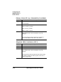
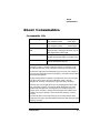
Centronics
Parallel Cable
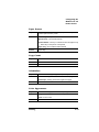
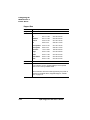
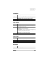
Specifications
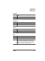
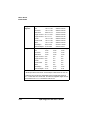
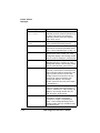
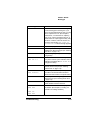
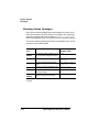
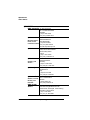
Signal Pin No.
Signal Description
Direction
10
Acnlg-
Out
11
Busy+
Out
12
Pe+
Out
13
Select
Out
14
Autofeed
In
15
Reserved
-
16
Ground
-
17
Ground
-
18
Vcc Test
-
19-30
Ground
-
31
Iprime
In
32
Fault-
Out
33
Reserved
-
34
Reserved
-
35
Reserved
-
36
Selectin
In
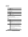
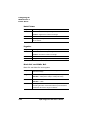
Notes to the Parallel Pinouts Table
n
Direction refers to the direction of signal flow as viewed from the
printer.
n
Return denotes “twisted-pair return” and is to be connected at
signal-ground level. When wiring the interface, be sure to use a
twisted-pair cable for each signal and never fail to complete connection on the return side. To prevent noise effectively, these
cables should be shielded and connected to the chassis of the
system unit and printer, respectively.
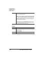
n
All interface conditions are based on Transistor-Transistor Logic
(TTL) level. Both the rise and fall times of each signal must be
less than 0.2 microseconds.
n
Data transfer must be carried out by recognizing the ACKNLG or
BUSY signal.
Technical Specifications
B-5