1
APPENDIX:
SP MODE TABLES
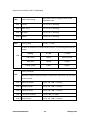
R E V I S I O N H I S T O RY
Pag e
Date
Ad d ed / Upd ated / New
45
05/21/2009
Updated Information - SP 5801 (D068/D069)
86
03/17/2009
Updated Information - SP 5873
138
05/19/2009
Updated Information – SP1001
164
05/21/2009
Updated Information - SP 5801 (D067/D072)
System Service Mode (F/SPF: D068/D069)
5. APPENDIX: SP MODE TABLES
5.1 SYSTEM SERVICE MODE (F/SPF: D068/D069)
5.1.1 SERVICE MODE TABLES
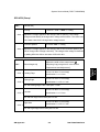
SP1-XXX (Feed)
1001*
LE Registration
1001 1 All Trays
1001 2 By-pass
[–9.0 to 9.0 / 0.0 / 0.1 mm/step]
Adjusts the leading-edge registration
(
"Adjusting Copy Image Area" in the section
"Replacement and Adjustment").
1001 3 Duplex
S-to-S Regist
1002 1 1st Tray
1002 2 2nd Tray
[–9.0 to 9.0 / 0.0 / 0.1 mm/step]
Adjusts the side-to-side registration
(
"Adjusting Copy Image Area" in the section
"Replacement and Adjustment"). SP1-002-001
1002 3 3rd Tray
1002 5 By-pass
is applied to all trays. SP1-002-002, 003 and
005 adjusts the difference from SP1-002-001.
Adjusts the side-to-side registration of the 2nd
1002 6 Duplex
side in duplex copying. The 1st side is adjusted
by SP1-002-001 through 005.
SM Appendix
5-1
D067/D068/D069/D072
Appendix:
SP Mode
Tables
1002*
System Service Mode (F/SPF: D068/D069)
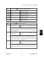
1003*
Paper Feed Timing
Adjusts the amount of paper buckle on the
registration roller.
1003 1 1st tray
[0 to 10 / 5 / 1 mm/step]
1003 3 Bank Trays
[0 to 10 / 5 / 1 mm/step]
1003 4 By-pass
[0 to 10 / 5 / 1 mm/step]
1003 5 Duplex
[0 to 20 / 5 / 1 mm/step]
1103*
Fusing Idling
[0 = No / 1 = Yes]
Enables or disables the contact-release control. The following table lists the
results.
Setting
0 = No
1 = Yes
C-R control
Works
Does not work
Idling time
Shorter
Longer
Fusing quality
Lower
Higher
1103 1
Fusing Temp Adj
1105*
Adjusts the target fusing temperature. Note that the thermistor is at the center
of the hot roller.
1105 1 Warm Up-Center
[140 to 180 / 160 / 1°C/step]
1105 3 Standby-Center
[140 to 160 / 150 / 1°C/step]
1105 5 Copying-Center
[140 to 180 / 160 / 1°C/step]
1105 7 Low Level 2-Center
[0 to 80 / 60 / 1°C/step]
1105 9 Thick-Center
[140 to 185 / 165 / 1°C/step]
D067/D068/D069/D072
5-2
SM Appendix
System Service Mode (F/SPF: D068/D069)
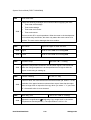
1106
Display Fusing
1106 1 (Center) Displays the fusing temperature.
Fusing Soft Start DFU
Adjusts the number of zero-cross cycles of the fusing lamp AC supply needed
1107*
to bring the fusing lamp power to 100% while bringing the lamp up to the
standby temperature or while copying. Increase this value if the machine is
experiencing sudden power dropouts.
1107 1
Warm Up Soft
Start
[0 = 10 times / 1 = 20 times / 2 = 50 times]
1107 2 Other Soft Start
[0 = 10 times / 1 = 20 times / 2 = 50 times / 3 = 1 time]
1107 3 Soft Stop Setting
[0: No / 1: Yes]
Set-Fusing Start
[0 = 1s / 1 = 1.5s / 2 = 2s]
Appendix:
SP Mode
Tables
1108*
1108 1 Specifies the interval for fusing-temperature control.
1109
1109 1
1110*
Nip Band Check
Conducts the nip band check (
"Adjusting Nip Band" in the section
"Replacement and Adjustment").
Fan Control Timer
[30 to 60 / 30 / 1 s/step]
Specifies the fan control time. The fan motor keeps its operating speed for the
1110 1
specified time before changing the speed or stopping. The fan control timer
prevents the exhaust fan from suddenly stopping. This function protects the
copier from overheating.
SM Appendix
5-3
D067/D068/D069/D072
System Service Mode (F/SPF: D068/D069)
1159*
Fusing Jam SC
[0 = No / 1 = Yes]
Enables or disables consecutive jam detection at the fusing unit. If this SP is
1159 1 set to "1" (default: 0), consecutive fusing jam alarm occurs (SC559) when the
machine detects three consecutive paper jams at the fusing unit.
1902
Display-AC Freq.
Displays the fusing lamp power control frequency (as detected by the zero
1902 1 cross signal generator). The displayed value is 1/5 the actual frequency: 10
and lower = 50 Hz, 11 and higher = 60 Hz.
1911*
By-pass Envelope
[0 = No / 1= Yes]
The program dedicated to envelope printing runs when you enable this
1911 1
program (SP1-911-001) and you select “Thick Paper” as the paper type of the
by-pass tray ( > System Settings > Tray Paper Settings > Paper Type:
Bypass Tray).
D067/D068/D069/D072
5-4
SM Appendix
System Service Mode (F/SPF: D068/D069)
SP2-XXX (Drum)
2001*
CR Bias Adj
Printing
[–2100 to –1500 / –1650 / 1 V/step]
2001 1 Adjusts the voltage applied to the charge roller for printing. The voltage
changes automatically as charge-roller voltage control works. The value here
is the base value for the charge-roller voltage control.
ID sensor pattern
[0 to 400 / 300 / 1 V/step]
2001 2 Adjusts the voltage applied to the charge roller for the ID sensor pattern (as
part of charge-roller voltage correction). The charge-roller voltage is obtained
by adding SP2-001-002 to the value of SP2-001-001.
Adjusts the width of the erased area (
2101*
Erase Margin Adj
"Adjusting Copy Image Area" in the section
2101 1 Leading Edge
Trailing Edge
2101 2
[0.0 to 9.0 / 3.0 / 0.1 mm/step]
Specification: 2 ± 1.5 mm
[0.0 to 9.0 / 4.0 / 0.1 mm/step]
Specification: 2 +2.5/–1.5 mm
The rear trailing edge is this value plus 1.2 mm.
Left side
2101 3
[0.0 to 9.0 / 2.0 / 0.1 mm/step]
Specification: 2 ± 1.5 mm
The rear left edge is this value plus 0.3 mm.
Right side
2101 4
[0.0 to 9.0 / 2.0 / 0.1 mm/step]
Specification: 2 +2.5/–1.5 mm
The rear right edge is this value plus 0.3 mm.
SM Appendix
5-5
D067/D068/D069/D072
Appendix:
SP Mode
Tables
"Replacement and Adjustment").
System Service Mode (F/SPF: D068/D069)
2201*
Dv Bias Adj
Printing
[–1500 to –200 / –650 / 1 V/step]
Adjusts the voltage applied to the development roller for printing. Image
2201 1
density becomes higher when you specify a smaller value (a greater absolute
value). Image density becomes lower when you specify a greater value (a
smaller absolute value).
ID sensor pattern
[–2 = LL (220 V) / -1 = L (260 V) / 0 = N (300 V) /
1 = H (340 V) / 2 = HH (380 V)]
2201 2 Adjusts the voltage applied to the development roller for the ID sensor
pattern. The voltage applied is obtained by adding SP2-201-002 to
SP2-201-1. The setting affects ID sensor pattern density, which in turn affects
the toner supply.
2213*
Outputs After NE
[0 = 50 pages / 1 = 20 sheets]
2213 1
Sets the number of copy/print/fax pages that can be made after toner
near-end has been detected. Reduce the number of pages if the user
normally makes copies with a high image ratio.
2214
2214 1
Develpr Initialize
Initializes the TD sensor toner supply target voltage and the TD sensor gain
value. Execute this SP replacing the developer or the TD sensor.
D067/D068/D069/D072
5-6
SM Appendix
System Service Mode (F/SPF: D068/D069)
2221
ID Error Analysis (
"ID Sensor Error Analysis (SP2-221)")
2221 1 Vsg
Displays the Vsg value.
2221 2 Vsp
Displays the Vsp value.
2221 3 PWM
Displays the PWM value.
2221 4 Vsdp
Displays the Vsdp value.
2221 5 Vt
Displays the Vt value.
2221 6 Vts
Displays the Vts value.
2301*
Tr Current Adj (
"Image Transfer Current").
Normal paper
2301 1
[–2 = –4 µA / –1 = –2 µA / 0 = 0 µA / 1 = 2 µA / 2
= +4 µA]
Adjusts the current applied to the transfer roller when feeding from a paper
spec) from a paper tray
Thick/Special
[–2 = –4 µA / –1 = –2 µA / 0 = 0 µA / 1 = 2 µA / 2
= +4 µA]
2301 2 Adjusts the current applied to the transfer roller when feeding from the
by-pass tray. Use a high setting (a) if the user normally feeds relatively thick
paper from the by-pass tray, or (b) if waste toner is re-attracted from the drum
(which can occur when using transparencies).
Duplex
2301 3
[–2 = –4 µA / –1 = –2 µ/ 0 = 0 µA / 1 = 2 µA / 2 =
+4 µA]
Adjusts the current applied to the transfer roller when carrying out a duplex
job. Use this SP if there is poor image transfer on the rear side of duplex
copies.
SM Appendix
5-7
D067/D068/D069/D072
Appendix:
SP Mode
Tables
tray. Use a high setting if the user normally feeds relatively thick paper (within
System Service Mode (F/SPF: D068/D069)
Cleaning
[–10 to 1 / –1 / 1 µA/step]
2301 4 Adjusts the current applied to the transfer roller for roller cleaning. Increase
the current if toner remains on the roller after cleaning. (Remaining toner may
cause dirty background on the rear side.)
2802
Forced Develpr Churn
Initializes the developer and checks the TD sensor output (Vt). The machine
mixes the developer for 2 minutes while reading and displaying the Vt value.
2802 1
The machine does not initialize the TD sensor output. If the machine has not
been used for a long period, prints may have a dirty background. In a case
like this, use this SP to mix the developer. The message “Completed” is
displayed when the program ends normally.
2906*
Tailing Crctn
Shift value
[0.0 to 1.0 / 0.0 / 0.1 mm/step]
2906 1 Shifts the image position at the intervals specified by SP2-906-002. When the
copier is continuously printing vertical lines (such as in tables), the paper may
not separate correctly. This SP can prevent this.
Interval
[1 to 10 / 1 / 1 page/step]
2906 2
Changes the interval of the image position shift specified by SP2-906-001.
2908
Forced Toner Supp
Supplies the toner to the development unit. The processing stops under
2908 1
either of the following conditions:
The toner density in the development unit reaches the standard level.
The processing has continued for two 2 minutes.
D067/D068/D069/D072
5-8
SM Appendix
System Service Mode (F/SPF: D068/D069)
2915*
Polygon Idling
[0 = None / 1 = 15 s / 2 = 25 s]
Specifies the polygon mirror motor idling time. The polygon mirror motor
starts its operation when an original is set, a key is pressed, or the platen
2915 1 cover or DF is opened. The motor stops if no manual operation is performed
for the specified time. When you set “0”, the motor does not stop while the
copier is in the standby status.
2921*
Toner Supply Mode
[0 = Sensor 1 / 1 = Sensor 2 (DFU)]
2921 1 Selects the toner supply mode. Keep the default setting as long as the TD
sensor is working.
2922*
Toner Supply Time
[0.1 to 5.0 / 0.6 / 0.1 s/step]
Adjusts the toner supply time. The toner supply motor remains on for the
specified time. To validate this setting, select “0” in SP2-921-001. Specify a
greater value if the user tends to make many copies having high proportions
of solid black image areas.
2926*
Standard Vt
[0.00 to 5.00 / 2.50 / 0.01 V/step] DFU
Adjusts Vts (the Vt value for new developer). The TD sensor output is
2926 1 adjusted to this value during the TD sensor initial setting process. This SP is
effective only when SP2-921001 is “0”, “1”, or “2”.
2927*
2927 1
ID Sensor Control
[0 = No / 1 = Yes]
Determines whether the ID sensor signal is referenced or not for the toner
density control. Keep the default value in usual operations.
SM Appendix
5-9
D067/D068/D069/D072
Appendix:
SP Mode
Tables
2922 1
System Service Mode (F/SPF: D068/D069)
2928
Toner End Clear
Clears the following messages and counters without supplying the toner:
2928 1
Toner near end message
Toner end message
Toner near end counter
Toner end counter
Do not use this SP in usual operations. When the toner in the development
unit is abnormally insufficient, the drum may attract the toner carrier to its
surface. The toner carrier damages the drum surface..
2929*
Vref Limits
Adjust the upper or lower Vref limit.
2929 1 Upper
[0.50 to 3.50 / 3.20 / 0.01V/step] DFU
2929 2 Lower
[0.50 to 3.50 / 0.70 / 0.01V/step] DFU
2994*
ID Detect Temp
[30 to 90 / 30 / 1 °C/step]
Adjusts the temperature threshold. The ID sensor signal is not referenced
2994 1 when the fusing temperature is at the specified level or higher while the
copier is recovering or starting up.
2996*
T Roller Cleaning
[0 = No / 1 = Yes]
Cleans or does not clean the transfer roller before each job. Select “1” if the
2996 1
backside of the paper becomes unclean when output. Note that the copier
takes a longer time to output the first copy when you select “1”. If you select
“0”, the transfer roller is never cleaned.
2998*
2998 1
Main Mag- print
Adjusts the magnification (
[–0.5 to +0.5 / 0.0 / 0.1%/step]
"Adjusting Copy Image Area" in the section
"Replacement and Adjustment"). The specification is 100 ± 1.0%.
D067/D068/D069/D072
5-10
SM Appendix
System Service Mode (F/SPF: D068/D069)
SP4-XXX (Scanner)
4008 1
4009*
4009 1
4010*
4010 1
4011*
4011 1
4012*
SubScan Mag (Scanner)
[-0.9 to +0.9 / 0.0 / 0.1%/step]
Adjusts the sub-scan magnification (
"Adjusting Copy Image Area" in the
section "Replacement and Adjustment").
Main Scan Mag (Scanner)
[–0.9 to +0.9 / 0.0 / 0.1%/step]
Adjusts the main-scan magnification (
"Adjusting Copy Image Area" in the
section "Replacement and Adjustment").
LE Scan Regist
[–5.0 to +5.0 / 0.0 / 0.1 mm/step]
Adjusts the leading edge registration (
"Adjusting Copy Image Area" in the
section "Replacement and Adjustment").
S-to-S Scanner Registration
[–2.0 to +2.0 / 0.0 / 0.1 mm/step]
Adjusts the side-to-side registration for scanning in platen mode (
"Adjusting Copy Image Area" in the section "Replacement and Adjustment").
Scan Erase Margin
[0 to 9.0 / 1.0 / 0.1 mm/step]
4012 1 Leading Edge
4012 2 Trailing Edge
Adjusts the scanning margin. Generally, the
scanning margin should be as little as possible. To
4012 3 Left Side
adjust the image area, use SP2-101.
4012 4 Right Side
4013
Scanner Free Run
4013 1 Conducts the scanner free run with the exposure lamp on.
SM Appendix
5-11
D067/D068/D069/D072
Appendix:
SP Mode
Tables
4008*
System Service Mode (F/SPF: D068/D069)
4015*
White Plate Scan
Start position
[–3.0 to +6.0 / 0.0 / 0.1 mm/step]
4015 1 Adjusts the scanning start position on the white plate. The base value is 17.8
mm from the scanner home position. This SP specifies the offset from this
base value.
Scanning Length
[–3.0 to +6.0 / 0.0 / 0.1 mm/step]
Adjusts the distance of the white plate scan. The scan begins from the start
4015 2
position (SP4-015-001) and ends at the specified distance. The base value is
2.0 mm. This SP decides the offset from this base value. Specify 0 (zero) or a
larger value.
4428
4428 1
4606
Scan Auto Adj
Conducts the automatic scanner adjustment. Use this SP after replacing the
white plate (
"Scanning" in the section "Replacement and Adjustment").
SBU Offset-Target
4607 1 EVEN
4607 2 ODD
4607 3 RED
[0 to 63 / 10 / 1 /step]
Adjusts the target black level for each signal.
These are used for offset adjustment in the SBU.
4607 4 GREEN
4607 5 BLUE
D067/D068/D069/D072
5-12
SM Appendix
System Service Mode (F/SPF: D068/D069)
4607
SBU Gain-Target
4607 1 EVEN
4607 2 ODD
4607 3 RED
[0 to 255 / 180 / 1 /step]
Adjusts the target white level for each signal.
These are used for gain adjustment in the SBU.
4607 4 GREEN
4607 5 BLUE
4623
SBU Offset-Result
4623 1 EVEN
4623 2 ODD
4623 3 RED
[0 to 255 / 0 / 1 /step]
Displays the result value of the offset adjustment
in the SBU.
Appendix:
SP Mode
Tables
4623 4 GREEN
4623 5 BLUE
4628
SBU Gain-Result
4628 1 EVEN
4628 2 ODD
4628 3 RED
[0 to 255 / 0 / 1 /step]
Displays the result value of the gain adjustment
in the SBU.
4628 4 GREEN
4628 5 BLUE
SM Appendix
5-13
D067/D068/D069/D072
System Service Mode (F/SPF: D068/D069)
4640
SBU Offset-Loop
4640 1 EVEN
4640 2 ODD
4640 3 RED
[0 to 10 / 0 / 1 /step]
Displays the number of the offset adjustment in
the SBU.
4640 4 GREEN
4640 5 BLUE
4641
SBU Gain-Loop
4641 1 EVEN
4641 2 ODD
4641 3 RED
[0 to 10 / 0 / 1 /step]
Displays the number of the gain adjustment in
the SBU.
4641 4 GREEN
4641 5 BLUE
4642
SBU Offsetpre-Loop
4642 1 EVEN
4642 2 ODD
4642 3 RED
[0 to 3 / 0 / 1 /step]
Displays the number of the pre-offset adjustment
in the SBU.
4642 4 GREEN
4642 5 BLUE
D067/D068/D069/D072
5-14
SM Appendix
System Service Mode (F/SPF: D068/D069)
4646
SBU Adj Error
4646 1 Offsetpre-Mono
4646 2 Offsetpre-Color
4646 3 Offset-Mono
4646 4 Offset-Color
[0 = Success / 1 = Failure]
Displays the result of SBU adjustment.
4646 5 Gain-Mono
4646 6 Gain-Color
4654*
SBU Offset-Adjust
4654 1 EVEN
4654 2 ODD
4654 3 RED
[0 to 255 / - / 1 /step]
Displays the offset value of the offset adjustment
Appendix:
SP Mode
Tables
in the SBU.
4654 4 GREEN
4654 5 BLUE
4658*
SBU Gain-Adjust
4658 1 EVEN
4658 2 ODD
4658 3 RED
[0 to 511 / - / 1 /step]
Displays the gain value of the gain adjustment in
the SBU.
4658 4 GREEN
4658 5 BLUE
SM Appendix
5-15
D067/D068/D069/D072
System Service Mode (F/SPF: D068/D069)
4685*
Gray Balance-Book
4685 1 RED
4685 2 GREEN
[128 to 383 / 256 / 1 /step]
Adjusts the coefficient of the gray balance
adjustment for the book scanning.
4685 3 BLUE
4686*
Gray Balance-DF
4686 1 RED
4686 2 GREEN
[128 to 383 / 256 / 1 /step]
Adjusts the coefficient of the gray balance
adjustment for the DF scanning.
4686 3 BLUE
4687*
White Balance
[222 to 281 / 256 / 1 /step]
4687 1 Adjust
Adjust the correction value for the white plate
adjustment.
Displays the current value of the white plate
4687 2 Result
adjustment.
If SP4-428 has not been done, this value is "0".
4690
White Peek Init
4658 1 EVEN
4658 2 ODD
4658 3 RED
[0 to 255 / - / 1 /step]
Displays the white offset value of the pre-offset
adjustment in the SBU.
4658 4 GREEN
4658 5 BLUE
D067/D068/D069/D072
5-16
SM Appendix
System Service Mode (F/SPF: D068/D069)
4693
Black Ave Init
4658 1 EVEN
4658 2 ODD
4658 3 RED
[0 to 255 / - / 1 /step]
Displays the black offset value of the pre-offset
adjustment in the SBU.
4658 4 GREEN
4658 5 BLUE
4902*
4902 1
4903*
Exposure Lamp ON
[0: OFF / 1: ON]
Turns the exposure lamp on or off. To turn on the exposure lamp, specify “1”;
to turn it off specify “0”.
ADS Level
[0 to 255 / 252 / 1/step]
4904*
ADS Lower Limit
Appendix:
SP Mode
Tables
4903 1 Adjusts the ADS level.
[0 to 255 / 80 / 1/step]
4904 1 Adjusts the ADS lower limit.
4905*
ADS Area Select
[0 = All / 1 = One]
Checks the whole area (0 = All) or the specific areas (1 = One) to adjust the
4905 1
ADS level. The specific areas are as follows:
ARDF: ±37.5 mm from the center
Platen Cover: 15 to 90 mm from the left edge
SM Appendix
5-17
D067/D068/D069/D072
System Service Mode (F/SPF: D068/D069)
Image Adj Selec
4921*
Copy
[0 to 10 / 0 / 1]
Selects which mode the settings from SP4-922 to SP4-932 are used for.
001
0 = None, 1 = Text 1, 2 =Text 2, 3= Photo 1, 4 = Photo 2, 5 = Photo 3, 6 =
Special 1, 7 = Special 2, 8 = Special 3, 9 = Special 4,
10 = Special 5
Fax
[0 to 5 / 0 / 1]
002 Selects which mode the settings from SP4-922 to SP4-932 are used for.
0 = None, 1 = Text 1, 2 = Text 2, 3 = Photo 1, 4 = Photo 2,
5 = Special 1
Scanner (Mono)
003
[0 to 4 / 0 / 1]
Selects which mode the settings from SP4-922 to SP4-932 are used for.
0 = None, 1 = Text 1, 2 = Text 2, 3= Photo 1, 4 = Photo 2
Scanner (Color)
004
[0 to 2 / 0 / 1]
Selects which mode the setting of SP4-935 is used for.
0 = None, 1 = Color Text, 2 = Color Photo
Scanner (Gray Scale)
005
[0 or 1 / 0 / - ]
Selects which mode the setting of SP4-936 is used for.
0 = None, 1 = Gray Scale
D067/D068/D069/D072
5-18
SM Appendix
System Service Mode (F/SPF: D068/D069)
Scanner Gamma
4922*
Selects “text” or “photo” as the priority output mode. This setting is applied to
all image processing modes of SP4-921.
001 Copy
[0=System default/ 1=Text/ 2=Photo]
002 Fax
003 Scanner
Notch Selection
Selects the value of the center ID adjustment notch for the ID adjustment
LEDs.
4923*
Normally the center notch is 3 (range 1-5). If –1 is selected, each notch
shifts down (becomes lighter). If +1 is selected, each notch shifts up
(becomes darker).
This setting is applied to all image processing modes of SP4-921.
001 Copy
002 Fax
[–1 = Light / 0 = Normal / +1 = Dark]
003 Scanner
SM Appendix
5-19
D067/D068/D069/D072
Appendix:
SP Mode
Tables
System Service Mode (F/SPF: D068/D069)
Texture Removal
Adjusts the texture removal level that is used with error diffusion. 0: The
default value for each mode is used. Text 1, Photo 2, Special 2, and Special 5
4926*
have a default of 3 and Photo 1-3 have a default of 1.
1: No removal applied.
2 to 5: Removal applied at the level specified here. The higher the setting
(level), the less clear the image will become (more texture removal). This
setting is only applied to the originals in SP4-921.
001 Copy
002 Fax
[0 to 6 / 0 / 1/step]
003 Scanner
Line Width
4927*
Adjusts the line width correction algorithm. Positive settings produce thicker
lines; negative settings produce thinner lines. This setting is only applied to
the originals in SP4-921.
001 Copy
002 Fax
[–2 to 2 / 0 / 1/step]
003 Scanner
D067/D068/D069/D072
5-20
SM Appendix
System Service Mode (F/SPF: D068/D069)
Independent Dot Erase
4928*
Selects the dot erase level. Higher settings provide greater erasure. This
setting is only applied to the originals in SP4-921.
001 Copy
002 Fax
[–2 to 2 / 0 / 1/step]
003 Scanner
Positive/Negative
4929*
[0 = No, 1 = Yes]
Inverts white and black. This setting is only applied to the originals in
SP4-921.
001 Copy
Sharpness-Edge
[–2 to 2 / 0 / 1/step]
4930*
Adjust the clarity. This setting is only applied to the originals in SP4-921.
001 Copy
002 Fax
003 Scanner
Sharpness-Solid
[–2 to 2 / 0 / 1/step]
4931*
Adjust the clarity. This setting is only applied to the originals in SP4-921.
001 Copy
002 Fax
003 Scanner
SM Appendix
5-21
D067/D068/D069/D072
Appendix:
SP Mode
Tables
002 Fax
System Service Mode (F/SPF: D068/D069)
Sharpness-Low ID
[–2 to 2 / 0 / 1/step]
4932*
Adjust the clarity. This setting is only applied to the originals in SP4-921.
001 Copy
002 Fax
003 Scanner
4935*
Color Image Adjust
Main Scan MTF Level
[0 to 3 / 0 / 1/step]
001 Adjust the MTF level for the main scan. This setting is only activated for the
specified mode with SP4-921-004.
0: None, 1: Weak, 2: Middle, 3: Strong
Main Scan MTF Strength
[0 to 5 / 0 / 1/step]
002 Adjust the MTF strength for the main scan. This setting is only activated for
the specified mode with SP4-921-004.
0: 1, 1: 1/32, 2: 1/16, 3: 1/8, 4: 1/4, 5: 1/2
Sub Scan MTF Level
[0 or 1 / 0 / 1/step]
003 Turns on or off the MTF for the sub scan. This setting is only activated for the
specified mode with SP4-921-004.
0: No, 1: Yes
Sub Scan MTF Strength
[0 to 5 / 0 / 1/step]
004 Adjust the MTF strength for the sub scan. This setting is only activated for the
specified mode with SP4-921-004.
0: 1, 1: 1/32, 2: 1/16, 3: 1/8, 4: 1/4, 5: 1/2
D067/D068/D069/D072
5-22
SM Appendix
System Service Mode (F/SPF: D068/D069)
Smooth Level
[0 to 2 / 0 / 1/step]
005 Adjust the smooth level. This setting is only activated for the specified mode
with SP4-921-004.
0: None, 1: Weak, 2: Strong
Brightness
006
[0 to 255 / 128 / 1/step]
Adjust the brightness level. This setting is only activated for the specified
mode with SP4-921-004.
Contrast
007
[0 to 255 / 128 / 1/step]
Adjust the contrast level. This setting is only activated for the specified mode
with SP4-921-004.
Gray Scale Image Adjust
Main Scan MTF Level
[0 to 15 / 0 / 1/step]
001 Adjust the MTF level for the main scan. This setting is only activated for the
specified mode with SP4-921-004.
0: None, 1: Level 1 to 15: Level 15
Main Scan MTF Strength
[0 to 5 / 0 / 1/step]
002 Adjust the MTF strength for the main scan. This setting is only activated for
the specified mode with SP4-921-004.
0: 1, 1: 1/32, 2: 1/16, 3: 1/8, 4: 1/4, 5: 1/2
Sub Scan MTF Level
[0 to 13 / 0 / 1/step]
003 Adjust the MTF level for the sub scan. This setting is only activated for the
specified mode with SP4-921-004.
0: No, 1: Level 1 to 13: Level 13
SM Appendix
5-23
D067/D068/D069/D072
Appendix:
SP Mode
Tables
4936*
System Service Mode (F/SPF: D068/D069)
Sub Scan MTF Strength
[0 to 5 / 0 / 1/step]
004 Adjust the MTF strength for the sub scan. This setting is only activated for the
specified mode with SP4-921-004.
0: 1, 1: 1/32, 2: 1/16, 3: 1/8, 4: 1/4, 5: 1/2
Smooth Level
[0 to 7 / 0 / 1/step]
005 Adjust the smooth level. This setting is only activated for the specified mode
with SP4-921-004.
0: None, 1: Level 1 to 7: Level 7
Brightness
006
[0 to 255 / 128 / 1/step]
Adjust the brightness level. This setting is only activated for the specified
mode with SP4-921-004.
Contrast
007
[0 to 255 / 128 / 1/step]
Adjust the contrast level. This setting is only activated for the specified mode
with SP4-921-004.
4941*
White Line Erase
[0 to 2 / 1 / 1/step]
Selects the white line erase level.
0: None,
4941 1 1: Weak,
2: Strong
This setting is effective for all modes.
0: White line erase is not used, and white level correction is used
instead·
This setting is applied regardless of what mode has been selected in
SP4-921.
D067/D068/D069/D072
5-24
SM Appendix
System Service Mode (F/SPF: D068/D069)
4942*
Black Line Erase
[0 to 3 / 2 / 1/step]
Selects the black line erase level. This setting is effective only when originals
are scanned by the DF.
4942 1 [0 = No / 1 = Very weak / 2 = Weak / 3 = Strong]
This setting is applied regardless of what mode has been selected in
SP4-921.
4943*
WhitePapDetect BiLv
[0 to 255 / 64 / 1/step]
4943 1 Color2
[0 to 255 / 128 / 1/step]
4943 1 Color3
[0 to 255 / 128 / 1/step]
Appendix:
SP Mode
Tables
4943 1 Gray Scale
SM Appendix
5-25
D067/D068/D069/D072
System Service Mode (F/SPF: D068/D069)
SP5-XXX (Mode)
All Indicators On
5001
5001 1
5024*
Turns on all LEDs. The LCDs turn on and off every 3 seconds. Press the
reset key to end this program.
mm/inch Selection
Selects whether mm or inches are used in the display.
001
After selecting the number, you must turn the main power switch off
and on.
Europe/Asia model: [0: mm / 1: inch]
American model: [0: mm / 1: inch]
5045*
According Counter
Displays the number of the installed counter.
[0 to 2 / 0 / 1 /step]
5045 1 Counter Method
0: 1 counter (Total)
1: 2 counters (Total and Prints)
2: 2 counters GPC
5055
Display IP address
Displays or does not display the IP address
001 Display IP address
CTL
on the LCD.
[0 or 1 / 0 / -]
0: No (Not display), 1: Yes (Display)
D067/D068/D069/D072
5-26
SM Appendix
System Service Mode (F/SPF: D068/D069)
5056
Coverage Counter
Displays or does not display the coverage
001 Coverage Counter
CTL
counter on the LCD.
[0 or 1 / 0 / -]
0: Not display, 1: Display
5062
Part Replacement
Displays or does not display the PCU yield on
001 PCU
CTL
the LCD.
[0 or 1 / 0 / -]
0: Not display, 1: Display
5066
PM Parts Display
Displays or does not display the PM part
CTL
button on the LCD.
Appendix:
SP Mode
Tables
001 PM Parts Display
[0 or 1 / 0 / -]
0: Not display, 1: Display
5067
Part Replacement Ope
Selects the service maintenance or user
001 PCU
CTL
maintenance for PCU.
[0 or 1 / 0 / -]
0: Service, 1: User
SM Appendix
5-27
D067/D068/D069/D072
System Service Mode (F/SPF: D068/D069)
5113
Optional Counter Type
This program specifies the counter type.
0: None
1: Key card (RK 3, 4)
001 Opt Cnt Type 1
CTL
2: Key card (down)
3 to 10: (Japan only)
11: Exp. Key card (Add)
12: Exp. Key card (Deduct)
This program specifies the external counter
type.
002 Opt Cnt Type 2
CTL
0: None
1: Expansion Device type 1
2: Expansion Device type 2
3: Expansion Device type 3
5114
Optional Counter I/F
CTL
[0: Not installed/ 1: Installed (scanning
accounting)]
001 MF Key Card Ext. Japan use
5118
Disable Copying
CTL
[0: Not disabled/ 1: Disabled]
001 This program disables copying.
D067/D068/D069/D072
5-28
SM Appendix
System Service Mode (F/SPF: D068/D069)
5120*
Clr For Cut Remove
[0=Yes / 1=Standby only / 2=No]
Specifies the condition to reset the copy job settings when the key counter is
removed.
5120 1
0: Y = Yes: The settings are cleared when the counter is removed.
1: StdBy = Standby only: The settings are cleared when the counter is
removed at the end of a job.
2: N = No: The settings are not cleared under either condition.
As for duplex copying, the job settings are always preserved regardless of
these setting.
5121*
Counter Up Timing
[0 = Feed In / 1 = Exit]
Selects the count-up timing.
0 = Feed: At each paper feed
1= Exit: At each paper exit
Fax Prnt Cnt Off
5167
Enables or disables the automatic print out without an accounting device. This
SP is used when the receiving fax is accounted by an external accounting
device.
[ 0 or 1 / 0 / – ]
001 Fax Prnt Cnt Off
CTL
0: Automatic printing
1: No automatic printing
CE Login
5169
If you change the printer bit switches, you must ‘log in’ to service mode with
this SP before you go into the printer SP mode.
[0 or 1 / 0 / - ]
001 CE Login
CTL
0: Disabled
1: Enabled
SM Appendix
5-29
D067/D068/D069/D072
Appendix:
SP Mode
Tables
5121 1 System Service Mode (F/SPF: D068/D069)
5188
Copy NV Version
001 Copy NV Version
Displays the NVRAM version in the
CTL
controller board.
Set Time
Adjusts the RTC (real time clock) time setting for the local time zone.
Examples: For Japan (+9 GMT), enter 540 (9 hours x 60 min.)
DOM: +540 (Tokyo)
5302
NA :-300 (New York)
EU :+ 60 (Paris)
CH :+480 (Peking)
TW :+480 (Taipei)
AS :+480 (Hong Kong)
002 Time Difference
D067/D068/D069/D072
CTL
#
[-1440 to 1440 / Area / 1 min./step ]
5-30
SM Appendix
System Service Mode (F/SPF: D068/D069)
Summer Time
5307
[ 0 or 1 / NA, EU, ASIA / 1 /step]
ON/OFF
-
0: Disabled
1: Enabled
NA and EUR: 1, ASIA: 0
001
Enables or disables the summer time mode.
Make sure that both SP5-307-3 and -4 are correctly set. Otherwise,
this SP is not activated even if this SP is set to "1".
Start
-
-
Specifies the start setting for the summer time mode.
There are 8 digits in this SP. For months 1 to 9, the "0" cannot be input in the
first digit, so the eight-digit setting for -2 or -3 becomes a seven-digit setting.
1st and 2nd digits: The month. [1 to 12]
003 4th digit: The day of the week. [0 to 6 = Sunday to Saturday]
5th and 6th digits: The hour. [00 to 23]
7th digit: The length of the advanced time. [0 to 9 / 1 hour
/step]
8th digit: The length of the advanced time. [0 to 5 / 10 minutes /step]
For example: 3500010 (EU default)
The timer is advanced by 1 hour at am 0:00 on the 5th Sunday in March
The digits are counted from the left.
Make sure that SP5-307-1 is set to "1".
SM Appendix
5-31
D067/D068/D069/D072
Appendix:
SP Mode
Tables
3rd digit: The week of the month. [1 to 5]
System Service Mode (F/SPF: D068/D069)
End
-
-
Specifies the end setting for the summer time mode.
There are 8 digits in this SP.
1st and 2nd digits: The month. [1 to 12]
004 3rd digit: The week of the month. [0 to 5]
4th digit: The day of the week. [0 to 6 = Sunday to Saturday]
5th and 6th digits: The hour. [00 to 23]
The 7th and 8th digits must be set to "00".
The digits are counted from the left.
Make sure that SP5-307-1 is set to "1".
Access Control
5401
When installing the SDK application, SAS (VAS) adjusts the following
settings. DFU
103 DocAcl
CTL
104 Authentication Time
CTL
[ 0 to 255 / 0 / 1 /step]
Selects the log out type for the
extend authentication device.
162 Extend Certification
CTL
Bit 0: Log-out without an IC card.
0: Not allowed (default)
1: Allowed
200 SDK1 Unique ID
CTL
201 SDK1 Certification Method
CTL
210 SDK2 Unique ID
CTL
211 SDK2 Certification Method
CTL
220 SDK3 Unique ID
CTL
“SDK” is the “software
development kit”. This data can be
D067/D068/D069/D072
5-32
converted from SAS (VAS) when
installed or uninstalled. (DFU)
SM Appendix
System Service Mode (F/SPF: D068/D069)
221 SDK3 Certification Method
CTL
230 SDK Cert
CTL
Enables or disables the log-out
confirmation option.
Bit0: Log-out confirmation option
0: Enable (default), 1: Disable
240 Detail Option
CTL
Selects the automatic log-out time.
Bit1 and 2: Automatic log-out timer
reduction
00: 60 seconds (default), 01:10
seconds, 10: 20seconds, 11: 30
seconds
User Code Clear
001
Clears the counts for the user codes assigned by the key operator to restrict
the use of the machine. Press [Execute] to clear.
Appendix:
SP Mode
Tables
5404
LDAP Certification
5411
Easy Certification
Determines whether easy LDAP certification is done.
004
[0 to 1/1/1]
1: On
0: Off
Password Null Not Permit
This SP is referenced only when SP5411-4 is set to "1" (On).
005
[0 to 1/0/1]
0: Password NULL not permitted.
1: Password NULL permitted.
SM Appendix
5-33
D067/D068/D069/D072
System Service Mode (F/SPF: D068/D069)
Lockout Setting
5413
Lockout On/Off
Switches on/off the lock on the local address book account.
001
[0 to 1/0/1]
0: Off
1: On
Lockout Threshold
002 Sets a limit on the frequency of lockouts for account lockouts.
[1 to 10/5/1]
Cancel On/Off
Determines whether the system waits the prescribed time for input of a correct
user ID and password after an account lockout has occurred.
003
[0 to 1/0/1]
0: Off (no wait time, lockout not cancelled)
1: On (system waits, cancels lockout if correct user ID and password are
entered.
Cancel Time
Determines the length of time that the system waits for correct input of the
004
user ID and password after a lockout has occurred. This setting is used only if
SP5413-3 is set to "1" (on).
[1 to 999/60/1 min.]
D067/D068/D069/D072
5-34
SM Appendix
System Service Mode (F/SPF: D068/D069)
5414
Access Mitigation
Mitigation On/Off
Switches on/off masking of continuously used IDs and passwords that are
001 identical.
[0 to 1/0/1]
0: Off
1: On
Mitigation Time
002 Sets the length of time for excluding continuous access for identical user IDs
and passwords.
[0 to 60/15/1 min.]
5415
Password Attack
001 Sets the number of attempts to attack the system with random passwords to
gain illegal access to the system.
[0 to 100/30/1 attempt]
Detect Time
002 Sets the time limit to stop a password attack once such an attack has been
detected.
[1 to 10/5/1 sec.]
SM Appendix
5-35
D067/D068/D069/D072
Appendix:
SP Mode
Tables
Permissible Number
System Service Mode (F/SPF: D068/D069)
5416
Access Info
User Max Num
001 Limits the number of users used by the access exclusion and password attack
detection functions.
[50 to 200/200/1 users]
Password Max Num
002 Limits the number of passwords used by the access exclusion and password
attack detection functions.
[50 to 200/200/1 passwords]
Monitor Interval
003 Sets the processing time interval for referencing user ID and password
information.
[1 to 10/3/1 sec.]
5417
Access Attack
Permissible Num
001 Sets a limit on access attempts when an excessive number of attempts are
detected for MFP features.
[0 to 500/100/1]
Attack Detect Time
002 Sets the length of time for monitoring the frequency of access to MFP
features.
[10 to 30/10/1 sec.]
D067/D068/D069/D072
5-36
SM Appendix
System Service Mode (F/SPF: D068/D069)
Cert Waite
003 Sets the wait time to slow down the speed of certification when an excessive
number of access attempts have been detected.
[0 to 9/3/1 sec.]
Attack Max Num
Sets a limit on the number of requests received for certification in order to slow
004
down the certification speed when an excessive number of access attempts
have been detected.
[50 to 200/200/1 attempt]
5420
User Auth
These settings should be done with the System Administrator.
Note: These functions are enabled only after the user access feature has
Copy
Determines whether certification is required before a user can use the copy
001 applications.
[0 to 1/0/1]
0: On
1: Off
DS
Determines whether certification is required before a user can use the
011 document server.
[0 to 1/0/1]
0: On
1: Off
SM Appendix
5-37
D067/D068/D069/D072
Appendix:
SP Mode
Tables
been enabled.
System Service Mode (F/SPF: D068/D069)
Fax
Determines whether certification is required before a user can use the fax
021 application.
[0 to 1/0/1]
0: On
1: Off
Scanner
Determines whether certification is required before a user can use the scan
031 applications.
[0 to 1/0/1]
0: On
1: Off
Printer
Determines whether certification is required before a user can use the printer
041 applications.
[0 to 1/0/1]
0: On
1: Off
051 SDK1
061 SDK2
[0 or 1/ 0 / 1] 0: ON. 1: OFF
Determines whether certification is required before a user can
use the SDK application.
071 SDK3
D067/D068/D069/D072
5-38
SM Appendix
System Service Mode (F/SPF: D068/D069)
5431
External Auth User
CTL
-
010 Tag
011 Entry
012 Group
020 Mail
030 Fax
031 Fax Sub
032 Folder
033 Protect Code
034 Smtp Auth
035 Lsap Auth
Appendix:
SP Mode
Tables
036 Smb Ftp Fldr Auth
037 Acut Acl
038 Document ACL
040 Cert Crypt
SM Appendix
5-39
D067/D068/D069/D072
System Service Mode (F/SPF: D068/D069)
Authentication Error Code
5481
These SP codes determine how the authentication failures are displayed.
System Log Disp
Determines whether an error code appears in the system log after a user
001 authentication failure occurs.
[0 to 1/0/1]
0: Off
1: On
Panel Disp
Determines whether an error code appears on the operation panel after a user
002 authentication failure occurs.
[0 to 1/1/1]
1: On
0: Off
MF Keycard Japan Only
Job Permit Setting
5490
Sets up operation of the machine with a keycard.
[0 to 1/0/1]
0: Disabled. Cancels operation if no code is input.
1: Enabled. Allows operation if another code is input and decrements the
counter once for use of the entered code.
D067/D068/D069/D072
5-40
SM Appendix
System Service Mode (F/SPF: D068/D069)
PM Alarm Interval
5501
CTL
-
[ 0 to 9999 / 0 / 1 /step]
001 Printout
0: Alarm off
1 to 9999: Alarm goes off when the PM counter
reaches the specified value (1 to 9999) x 1000.
[ 0 or 1 / 1 / – ]
002 ADF
0: No alarm sounds
1: Alarm sounds after the number of originals passing
through the A(R)DF ≥ 10,000
Jam Alarm
5504
CTL
-
Sets the alarm to sound for the specified jam level (document misfeeds are
001
not included).
[ 0 to 3 / 3 / 1 /step]
5505*
Appendix:
SP Mode
Tables
0: Zero (Off), 1: Low (2.5K jams), 2: Medium (3K jams), 3: High (6K jams)
Error Alarm
Sets the error alarm level.
The error alarm counter counts "1" when any SC is detected. However, the
001
error alarm counter decreases by "1" when any SC is not detected during
specified sheets of copies (for example, default 1500 sheets).
The error alarm occurs when the SC error alarm counter reaches "5".
[0 to 255 / 10 / 100 copies per step]
SM Appendix
5-41
D067/D068/D069/D072
System Service Mode (F/SPF: D068/D069)
5507
Supply Alarm
CTL
-
001 Paper Size
0: Off, 1: On,
003 Toner
0: Off, 1: On,
005 Drum
0: Off, 1: On,
080 Toner Call Timing
0: Toner is replaced (default)
1: Toner near end or end
128 Interval :Others
132 Interval :A3
133 Interval :A4
134 Interval :A5
141 Interval :B4
[250 to 10000 / 1000 / 1 /step]
142 Interval :B5
160 Interval :DLT
164 Interval :LG
166 Interval :LT
172 Interval :HLT
D067/D068/D069/D072
5-42
SM Appendix
System Service Mode (F/SPF: D068/D069)
5508*
Auto Call Setting
Jam Remains
CTL
-
0: Disable, 1: Enable
001*
Enables/disables initiating a call for an unattended paper jam.
Frequent Jams
0: Disable, 1: Enable
002*
Enables/disables initiating a call for consecutive paper jams.
Door Open
0: Disable, 1: Enable
003*
Enables/disables initiating a call when the front door remains open.
Jam Remains: Time
011*
[ 03 to 30 / 10 / 1 minute /step]
Sets the time a jam must remain before it becomes an “unattended paper
jam”. This setting is enabled only when SP5508 004 is set to 1.
Freq Jam: # of Time
Sets the number of consecutive paper jams required to initiate a call. This
setting is enabled only when SP5508 004 is set to 1.
Door Open: Time
[ 03 to 30 / 10 / 1 minute/step]
013* Sets the length of time the door remains open before the machine initiates a
call.
This setting is enabled only when SP5508 004 is set to 1.
SM Appendix
5-43
D067/D068/D069/D072
Appendix:
SP Mode
Tables
012*
[ 02 to 10 / 5 / 1 /step]
System Service Mode (F/SPF: D068/D069)
SC/Alarm Setting
5515
CTL
-
With @Remote in use, these SP codes can be set to issue an SC call when an
SC error occurs. If this SP is switched off, the SC call is not issued when an
SC error occurs.
001 SC Call
002 Service Parts Near End
003 Service Parts End
[0 or 1 / 1 / -]
004 User Call
0: Off, 1: On
006 Communication Test
007 Machine Information
008 Alarm Notice
010 Supply Automatic Order
[0 or 1 / 0 / -] 0: Off,1: On
011 Supply Management Report
012 Jam/Door Open Call
D067/D068/D069/D072
[0 or 1 / 1 / -] 0: Off,1: On
5-44
SM Appendix
System Service Mode (F/SPF: D068/D069)
Rev. 05/20/2009
5801
[Memory Clear]
(Refer to IMPORTANT NOTE is Sect 6.2)
Before executing any of these SP codes, print an SMC Report.
All Clear
001
Initializes items SP5801-002 to -014 below.
Turn the main power switch off and on after executing this SP.
SCS
-
-
-
-
-
-
-
-
003
Clears the system settings.
IMH
004
Clears IMH data. DFU
MCS
005
Clears MCS data. DFU
Copier
006
Clears the copy application settings.
Fax
-
Appendix:
SP Mode
Tables
⇒
-
007
Clears the fax application settings.
Printer
-
-
008
Clears the printer application settings.
Scanner
-
-
009
Clears the scanner application settings.
GWWS
010
-
-
Delete the netfile application management files and thumbnails, and
initializes the job login ID.
SM Appendix
5-45
D067/D068/D069/D072
System Service Mode (F/SPF: D068/D069)
NCS
-
-
Initializes the system default and interface settings (IP address also),
SmartNetMonitor for Admin, WebImageMonitor settings, and the TELNET
011
settings.
The name of Apple talk is not cleared only if this SP is executed.
Turns off and on after executing this SP.
R-FAX
012
-
-
Initializes the job login ID, SmartNetMonitor for Admin, job history, and local
storage file numbers.
Clear DCS Setting
-
-
014
Initializes the DCS (Delivery Control Service) settings.
Clr UCS Setting
-
-
015
Initializes the UCS (User Information Control Service) settings.
MIRS Setting
-
-
016
Initializes the MIRS (Machine Information Report Service) settings.
CCS
-
-
017
Initializes the CCS (Certification and Charge-control Service) settings.
SRM Memory Clr
-
-
018
Initializes the SRM (System Resource Manager) settings.
LCS
-
-
019
Initializes the LCS (Log Count Service) settings.
Web Apli
-
-
020
Initializes Web application settings.
D067/D068/D069/D072
5-46
SM Appendix
System Service Mode (F/SPF: D068/D069)
Machine Free Run
5802
[0 or 1 / 0 / - ] 0: No, 1: Yes
Conducts machine free run (including the scanner unit). Set "1" and then
5802 1 press “ ” key. Press “
” key again to start "Free Run". When this SP is set
to "0", the machine operates normally even “ ” key is pressed.
Input Check
5803
"Input Check" in this chapter.
Output Check
5804
"Output Check" in this chapter.
Area Selection
5807*
Selects the display language.
2 North America, 3 Europe, 5 Asia, 6 China
NOTE: SC982 is displayed if you specify a language that is inconsistent with
your local model.
Machine No. Setting
5811*
Code Set
001
"Machine No. Setting" in this section.
SM Appendix
5-47
D067/D068/D069/D072
Appendix:
SP Mode
Tables
5807 1 SP5-807-001 is not cleared by SP5-801-002.
System Service Mode (F/SPF: D068/D069)
Service TEL
5812
Telephone
CTL
-
Sets the telephone number for a service representative. This number is
001 printed on the Counter List, which can be printed with the user’s “Counter”
menu.
This can be up to 20 characters (both numbers and alphabetic characters can
be input).
Facsimile
CTL
-
Sets the fax or telephone number for a service representative. This number is
002
printed on the Counter List.
This can be up to 20 characters (both numbers and alphabetic characters can
be input).
Supply
CTL
-
003 Use this to input the telephone number of your supplier for consumables.
Enter the number and press"StringIn" key.
Press the “Clear modes” key to delete the telephone number.
Sales
CTL
-
004 Use this to input the telephone number of your sales agency. Enter the
number and press #.
Press the “Clear modes” key to delete the telephone number.
D067/D068/D069/D072
5-48
SM Appendix
System Service Mode (F/SPF: D068/D069)
5816
[NRS Function]
CTL
-
Selects the remote service setting.
[ 0 to 2 / 2 / 1 /step]
001 I/F Setting
0: Remote service off
1: CSS remote service on
2: @Remote service on
Performs the CE Call at the start or end of the
service.
[0 or 1 / 0 / 1 /step]
002 CE Call
0: Start of the service, 1: End of the service
This SP is activated only when SP
5816-001 is set to “2”.
Enables or disables the remote service function.
003 Function Flag
[0 or 1 / 0 / 1 /step]
Uses or does not use the RCG certification by SSL
when calling the RCG.
007 SSL Disable
[0 or 1 / 0 / 1 /step]
0: Uses the RCG certification
1: Does no use the RCG certification
Specifies the connect timeout interval when calling
008 RCG Connect T/O
the RCG.
[1 to 90 / 10 / 1 second/step]
Specifies the write timeout interval when calling the
009 RCG Write Timeout
RCG.
[1 to 100 / 60 / 1 second/step]
SM Appendix
5-49
D067/D068/D069/D072
Appendix:
SP Mode
Tables
0: Disabled, 1: Enabled
System Service Mode (F/SPF: D068/D069)
Specifies the read timeout interval when calling the
010 RCG Read Timeout
RCG.
[1 to 100 / 60 / 1 second/step]
Enables/disables access via port 80 to the SOAP
011 Port 80
method.
[0 or 1 / 0 / – ]
0: Disabled, 1: Enabled
Selects the timing for the remote firmware updating.
013 RFU Timing
[0 or 1 / 0 / – ]
0: Any status of a target machine
1: Sleep or panel off mode only
Install Status
This SP displays the RCG device installation status.
022
0: RCG device not registered
1: RCG device registered
2: Device registered
Connect Mode (N/M)
023 This SP displays and selects the embedded RCG connection method.
0: Internet connection
1: Dial-up connection
NotiTime ExpTime DFU
061
Proximity of the expiration of the certification.
HTTP Proxy Use
062
This SP setting determines if the proxy server is used when the machine
communicates with the service center.
D067/D068/D069/D072
5-50
SM Appendix
System Service Mode (F/SPF: D068/D069)
HTTP Proxy Host
This SP sets the address of the proxy server used for communication
between embedded RCG-N and the gateway. Use this SP to set up or display
the customer proxy server address. The address is necessary to set up
063 embedded RCG-N.
The address display is limited to 127 characters. Characters beyond
the 127th character are ignored.
This address is customer information and is not printed in the SMC
report.
HTTP Proxy Port
This SP sets the port number of the proxy server used for communication
between embedded RCG N and the gateway. This setting is necessary to set
up embedded RCG-N.
This port number is customer information and is not printed in the
Appendix:
SP Mode
Tables
064
SMC report.
HTTP Proxy Aut Usr
This SP sets the HTTP proxy authentication user name.
065
The length of the name is limited to 31 characters. Any character
beyond the 31st character is ignored.
This name is customer information and is not printed in the SMC
report.
HTTP Proxy Aut Pass
This SP sets the HTTP proxy authentication password.
066
The length of the password is limited to 31 characters. Any character
beyond the 31st character is ignored.
This name is customer information and is not printed in the SMC
report.
SM Appendix
5-51
D067/D068/D069/D072
System Service Mode (F/SPF: D068/D069)
Cer Updt Cond
Displays the status of the certification update.
0
1
2
3
4
067
11
12
The certification used by embedded RCG is set correctly.
The certification request (setAuthKey) for update has been received
from the GW URL and certification is presently being updated.
The certification update is completed and the GW URL is being notified
of the successful update.
The certification update failed, and the GW URL is being notified of the
failed update.
The period of the certification has expired and a new request for an
update is being sent to the GW URL.
A rescue update for certification has been issued and a rescue
certification setting is in progress for the rescue GW connection.
The rescue certification setting is completed and the GW URL is being
notified of the certification update request.
The notification of the request for certification update has been
13
completed successfully, and the system is waiting for the certification
update request from the rescue GW URL
14
15
16
The notification of the certification request has been received from the
rescue GW controller, and the certification is being stored.
The certification has been stored, and the GW URL is being notified of
the successful completion of this event.
The storing of the certification has failed, and the GW URL is being
notified of the failure of this event.
D067/D068/D069/D072
5-52
SM Appendix
System Service Mode (F/SPF: D068/D069)
The certification update request has been received from the GW URL,
17
067
the GW URL was notified of the results of the update after it was
completed, but a certification error has been received, and the rescue
certification is being recorded.
18
The rescue certification of No. 17 has been recorded, and the GW URL
is being notified of the failure of the certification update.
Cer Abnml Cause
Displays a number code that describes the reason for the request for update
of the certification.
1
068
2
3
Normal. There is no request for certification update in progress.
Request for certification update in progress. The current certification
has expired.
An SSL error notification has been issued (after the certification has
expired).
Notification of shift from a common authentication to an individual
certification.
4
Notification of a common certification without ID2.
5
Notification that no certification was issued.
6
Notification that GW URL does not exist.
Cer: Updtt ReqID
069
The ID of the request for certification.
Firm Updating
083
Displays the status of the firmware update.
SM Appendix
5-53
D067/D068/D069/D072
Appendix:
SP Mode
Tables
0
System Service Mode (F/SPF: D068/D069)
Firm Up Usr Conf
This SP setting determines if the operator can confirm the previous version of
085
the firmware before the firmware update execution. If the option to confirm the
previous version is selected, a notification is sent to the system manager and
the firmware update is done with the firmware files from the URL.
Firmware Size
086
Allows the service technician to confirm the size of the firmware data files
during the firmware update execution.
CERT: Macro Vsn
087
Displays the macro version of the @Remote certification.
CERT: PAC Vsn
088
Displays the PAC version of the @Remote certification.
CERT: ID2 Code
089
Displays ID2 for the @Remote certification. Spaces are displayed as
underscores (_). Asterisks (*) indicate that no @Remote certification exists.
CERT: Subject
090 Displays the common name of the @Remote certification subject. CN = the
following 17 bytes. Spaces are displayed as underscores (_). Asterisks (*)
indicate that no DESS exists.
CERT: Seri Num
091
Displays serial number for the @Remote certification. Asterisks (*) indicate
that no DESS exists.
CERT: Issuer
092
Displays the common name of the issuer of the @Remote certification. CN =
the following 30 bytes. Asterisks (*) indicate that no DESS exists.
D067/D068/D069/D072
5-54
SM Appendix
System Service Mode (F/SPF: D068/D069)
CERT: St ExpTime
093
Displays the start time of the period for which the current @Remote
certification is enabled.
CERT: End ExpTime
094
Displays the end time of the period for which the current @Remote
certification is enabled.
Ins Country
Select from the list the name of the country where embedded RCG-M is
installed in the machine. After selecting the country, you must also set the
following SP codes for embedded RCG-M:
150
SP5816-153
SP5816-154
SP5816-161
0: Japan, 1: USA, 2: Canada, 3: UK, 4: Germany, 5: France
Appendix:
SP Mode
Tables
6: Italy, 7: Netherlands, 8: Belgium, 9: Luxembourg, 10: Spain
Aut Line Detect
Press [Execute].
Setting this SP classifies the telephone line where embedded RCG-M is
connected as either dial-up or push type, so embedded RCG-M can
151 automatically distinguish the number that connects to the outside line.
The current progress, success, or failure of this execution can be
displayed with SP5816 152.
If the execution succeeded, SP5816 153 will display the result for
confirmation and SP5816 154 will display the telephone number for the
connection to the outside line.
SM Appendix
5-55
D067/D068/D069/D072
System Service Mode (F/SPF: D068/D069)
Line Detect Rst
Displays a number to show the result of the execution of SP5816 151. Here is
a list of what the numbers mean.
0: Success
1: In progress (no result yet). Please wait.
152
2: Line abnormal
3: Cannot detect dial tone automatically
4: Line is disconnected
5: Insufficient electrical power supply
6: Line classification not supported
7: Error because fax transmission in progress – ioctl() occurred.
8: Other error occurred
9: Line classification still in progress. Please wait.
Dial/Push Select
This SP displays the classification (tone or pulse) of the telephone line to the
access point for embedded RCG-M. The number displayed (0 or 1) is the
result of the execution of SP5816 151. However, this setting can also be
changed manually.
153 [0 to 1 / 0 / 1 /step]
0: Tone Dialing Phone
1: Pulse Dialing Phone
Inside Japan "2" may also be displayed:
0: Tone Dialing Phone
1: Pulse Dialing Phone 10PPS
2: Pulse Dialing Phone 20PPS
D067/D068/D069/D072
5-56
SM Appendix
System Service Mode (F/SPF: D068/D069)
Outline Phone #
The SP sets the number that switches to PSTN for the outside connection for
embedded RCG-M in a system that employs a PBX (internal line).
If the execution of SP5816-151 has succeeded and embedded RCG-M
has connected to the external line, this SP display is completely blank.
154
If embedded RCG-M has connected to an internal line, then the number
of the connection to the external line is displayed.
If embedded RCG-M has connected to an external line, a comma is
displayed with the number. The comma is inserted for a 2 sec. pause.
The number setting for the external line can be entered manually
(including commas).
Dial Up User
Use this SP to set a user name for access to remote dial up. Follow these
156 rules when setting a user name:
Name length: Up to 32 characters
Spaces and # allowed but the entire entry must be enclosed by double
Appendix:
SP Mode
Tables
quotation marks (").
Dial Up Password
Use this SP to set a password for access to remote dial up. Follow these rules
157 when setting a user name:
Name length: Up to 32 characters
Spaces and # allowed but the entire entry must be enclosed by double
quotation marks (").
Phone Number
Use this SP to set the telephone number of the line where embedded RCG-M
161
is connected. This number is transmitted to and used by the Call Center to
return calls.
Limit: 24 numbers (numbers only)
SM Appendix
5-57
D067/D068/D069/D072
System Service Mode (F/SPF: D068/D069)
Ans Timing Adj
When the Call Center calls out to a embedded RCG-M modem, it sends a
repeating ID tone (*#1#). This SP sets the time the line remains open to send
162 these ID tones after the number of the embedded RCG-M modem is dialed up
and connected.
[0 to 24/ 1 /1 /step]
The actual amount of time is this setting + 2 sec. For example, if you set "2"
the line will remain open for 4 sec.
Access Point
This is the number of the dial-up access point for embedded RCG-M. If no
163 setting is done for this SP code, then a preset value (determined by the
country selected) is used.
Default: 0
Allowed: Up to 16 alphanumeric characters
Comm Line
This SP sets the connection conditions for the customer. This setting
dedicates the line to embedded RCG-M only, or sets the line for sharing
between embedded RCG-M and a fax unit.
[0 or 1 / 0 / - ]
164 0: Line shared by embedded RCG-M/Fax
1: Line dedicated to embedded RCG-M only
If this setting is changed, the copier must be cycled off and on.
SP5816 187 determines whether the off-hook button can be used to
interrupt an embedded RCG-M transmission in progress to open the
line for fax transaction.
Modem Serial Number
173
This SP displays the serial number registered for the embedded RCG-M.
D067/D068/D069/D072
5-58
SM Appendix
System Service Mode (F/SPF: D068/D069)
Lmt Resend Cncl
Normally, it is best to allow unlimited time for certification and ID2 update
requests, and for the notification that the certification has been completed.
174 However, embedded RCG-M generates charges based on transmission time
for the customer, so a limit is placed upon the time allowed for these
transactions.
If these transactions cannot be completed within the allowed time, do this SP
to cancel the time restriction.
186 RCG-C M Debut Bit SW DFU
FAX TX Priority
This SP determines whether pushing the off-hook button will interrupt an
embedded RCG-M transmission in progress to open the line for fax
transaction. This SP can be used only if SP5816-164 is set to "0".
[0 or 1/ 0 / - ]
progress. If the off-hook button is pushed during a embedded RCG-M
transmission, the button must be pushed again to set the fax unit on-hook
after the embedded RCG-M transmission has completed.
1: Enable. When embedded RCG-M shares a line with a fax unit, setting the
fax unit off-hook will interrupt a embedded RCG-M transmission in progress
and open the line for a fax transaction.
Polling Man Exc
200
Executes the polling test.
SM Appendix
5-59
D067/D068/D069/D072
Appendix:
SP Mode
Tables
187 0: Disable. Setting the fax unit off-hook does not interrupt a fax transaction in
System Service Mode (F/SPF: D068/D069)
Instl: Condition
Displays a number that indicates the status of the @Remote service device.
0: Neither the registered device by the external RCG nor embedded RCG
device is set.
1: The embedded RCG device is being set. Only Box registration is
201 completed. In this status the this unit cannot answer a polling request from
the external RCG.
2: The embedded RCG device is set. In this status the external RCG unit
cannot answer a polling request.
3: The registered device by the external RCG is being set. In this status the
embedded RCG device cannot be set.
4: The registered module by the external RCG has not started.
Instl: ID#
202
Allows entry of the number of the request needed for the embedded RCG.
Instl: Reference
203
Executes the inquiry request to the @Remote GateWay URL.
Instl: Ref Rslt
Displays a number that indicates the result of the inquiry executed with
SP5816-203.
0: Succeeded
1: Inquiry number error
204
2: Registration in progress
3: Proxy error (proxy enabled)
4: Proxy error (proxy disabled)
5: Proxy error (Illegal user name or password)
6: Communication error
7: Certification update error
8: Other error
9: Inquiry executing
D067/D068/D069/D072
5-60
SM Appendix
System Service Mode (F/SPF: D068/D069)
Instl: Ref Section
205 Displays the result of the notification sent to the device from the GW URL in
answer to the inquiry request. Displayed only when the result is registered at
the GW URL.
Instl: Rgstltn
206
Executes Embedded RCG Registration.
Instl: Rgstltn Rst
Displays a number that indicates the registration result.
0: Succeeded
2: Registration in progress
3: Proxy error (proxy enabled)
207
4: Proxy error (proxy disabled)
5: Proxy error (Illegal user name or password)
6: Communication error
Appendix:
SP Mode
Tables
7: Certification update error
8: Other error
9: Registration executing
SM Appendix
5-61
D067/D068/D069/D072
System Service Mode (F/SPF: D068/D069)
Instl Error Code
Displays a number that describes the error code that was issued when either
SP5816 204 or SP5816 207 was executed.
Cause
Code
Meaning
-11001
Chat parameter error
-11002
Chat execution error
-11003
Unexpected error
Illegal Modem
208
Parameter
-12002
Operation Error,
Incorrect Setting
-12003
-12004
D067/D068/D069/D072
Inquiry, registration attempted without
acquiring device status.
Attempted registration without execution of an
inquiry and no previous registration.
Attempted setting with illegal entries for
certification and ID2.
5-62
SM Appendix
System Service Mode (F/SPF: D068/D069)
Attempted dial up overseas without the
-2385
correct international prefix for the telephone
number.
Error Caused by
208 Response from
-2387
Not supported at the Service Center
-2389
Database out of service
-2390
Program out of service
-2391
Two registrations for same device
-2392
Parameter error
-2393
External RCG not managed
-2394
Device not managed
-2395
Box ID for external RCG is illegal
-2396
Device ID for external RCG is illegal
-2397
Incorrect ID2 format
-2398
Incorrect request number format
Instl Clear
209
Releases a machine from its embedded RCG setup.
Print Com Log
250
Prints the communication log.
SM Appendix
5-63
D067/D068/D069/D072
Appendix:
SP Mode
Tables
GW URL
System Service Mode (F/SPF: D068/D069)
NRS Address
5821
Sets the IP address of the RCG (Remote
002 RCG IP Address
Communication Gate) destination for call
processing at the remote service center.
[00000000h to FFFFFFFFh / 1 /step]
5824
5824 1
5825
5825 1
NVRAM Upload
"NVRAM Upload/Download" in this section.
NVRAM Download
"NVRAM Upload/Download" in this section.
D067/D068/D069/D072
5-64
SM Appendix
System Service Mode (F/SPF: D068/D069)
Network Setting
5828
050
1284 Compatibility
(Centro)
CTL
Enables or disables 1284 Compatibility.
[0 or 1 / 1 / 1 / step]
0: Disabled, 1: Enabled
Enables or disables ECP Compatibility.
[0 or 1 / 1 / 1 / step]
052 ECP (Centro)
0: Disabled, 1: Enabled
NOTE: This SP is activated only when
SP5-828-50 is set to "1".
Enables/disables Job Spooling.
065 Job Spooling
[0 or 1 / 0 / 1 / step]
0: Disabled, 1: Enabled
Treatment of the job when a spooled job exists at
Job Spooling Clear: Start power on.
Time
0: ON (Data is cleared)
1: OFF (Automatically printed)
Validates or invalidates the job spooling function
for each protocol.
0: Validates
1: Invalidates
bit0: LPR
069 Job Spooling (Protocol)
bit1: FTP
bit2: IPP
bit3: SMB
bit4: BMLinkS
bit5: DIPRINT
bit6: (Reserved)
bit7: (Reserved)
SM Appendix
5-65
D067/D068/D069/D072
Appendix:
SP Mode
Tables
066
System Service Mode (F/SPF: D068/D069)
Enables or disables the Telnet protocol.
090 TELNET (0: OFF 1: ON)
[ 0 or 1 / 1 / – ]
0: Disable, 1: Enable
Enables or disables the Web operation.
091 Web (0: OFF 1: ON)
[ 0 or 1 / 1 / – ]
0: Disable, 1: Enable
Active IPv6 Link
This is the IPv6 local address link referenced on the Ethernet or wireless LAN
145 (802.11b) in the format:
"Link Local Address" + "Prefix Length"
The IPv6 address consists of a total of 128 bits configured in 8 blocks of 16
bits each.
147
149
151
Active IPv6 Status
Address 1
Active IPv6 Status
Address 2
These SPs are the IPv6 status addresses (1 to 5)
referenced on the Ethernet or wireless LAN
Active IPv6 Status
(802.11b) in the format:
Address 3
"Status Address" + "Prefix Length"
The IPv6 address consists of a total of 128 bits
153
155
Active IPv6 Status
configured in 8 blocks of 16 bits each.
Address 4
Active IPv6 Status
Address 5
IPv6 Manual Setting Address
This SP is the IPv6 manually set address referenced on Ethernet or wireless
156 LAN (802.11b) in the format:
"Manual Set Address" + "Prefix Length"
The IPv6 address consists of a total of 128 bits configured in 8 blocks of 16
bits each.
D067/D068/D069/D072
5-66
SM Appendix
System Service Mode (F/SPF: D068/D069)
IPv6 Gateway Address
158 This SP is the IPv6 gateway address referenced on Ethernet or wireless LAN
(802.11b). The IPv6 address consists of a total of 128 bits configured in 8
blocks of 16 bits each.
IPv6 Stateless Auto Setting
Enables/disables the stateless automatic setting for Ethernet/wireless LAN
161 operation.
[0 to 1/1/1]
1: Enable
0: Disable
Web Item Invisible
Determines whether each item can be set in Websys.
236 [0x0000 to 0xffff/0xffff]
Bit 1: NetRICOH
Bit2-15: Reserved
Web Shopping Link Invisible
Determines whether the NetRICOH link is displayed on the Websys top page
237
and link page.
[0 to 1/1/1]
1: Display
0: No display
Web Supplies Link Invisible
Determines whether the consumable vendor link is displayed on the Websys
238
top page and link page.
[0 to 1/1/1]
1: Display
0: No display
SM Appendix
5-67
D067/D068/D069/D072
Appendix:
SP Mode
Tables
Bit2: Vendor for consumables
System Service Mode (F/SPF: D068/D069)
Web Link 1 Name
239 Determines whether a name entered for "URL1" is displayed on the Websys
link page. The name length is limited to 31 characters.
Web Link 1 URL
240 Sets the URL referenced for URL1 linked to the Websys linked page. The link
name is limited to 127 characters.
Web Link 1 Visible
Determines whether the link for URL1 is displayed on the Websys top page.
241 [0 to 1/1/1]
1: Display
0: No display
Web Link 2 Name
242 Determines whether a name entered for "URL2" is displayed on the Websys
link page. The name length is limited to 31 characters.
Web Link 2 URL
243 Sets the URL referenced for URL2 linked to the Websys linked page. The link
name is limited to 127 characters.
Web Link 2 Visible
Determines whether the link for URL2 is displayed on the Websys top page.
244 [0 to 1/1/1]
1: Display
0: No display
D067/D068/D069/D072
5-68
SM Appendix
System Service Mode (F/SPF: D068/D069)
HDD
5832
Enter the SP number for the partition to initialize, then press #. When the
execution ends, cycle the machine off and on.
001 HDD Formatting (All)
002 HDD Formatting (IMH)
003 Format Thumbnail
004 Format Job Log
005 Format Font
006 Format User Info
007 Format Rec Mail
008 Format Sed Mail
Appendix:
SP Mode
Tables
009 Format DFU data
010 Format All Log
011 Format Ridoc I/F
IEEE 802.11
5840
[1 to 11 or 13 / 11 or 13 / 1 /step]
Channel MAX
CTL
Europe: 1 to 13, default: 13
NA/ Asia: 1 to 11, default: 11
Sets the maximum number of channels available for data transmission via
006
wireless LAN. The number of channels available varies according to location.
The default settings are set for the maximum end of the range for each area.
Adjust the upper 4 bits to set the maximum number of channels. DFU
SM Appendix
Do not change the setting.
5-69
D067/D068/D069/D072
System Service Mode (F/SPF: D068/D069)
[ 1 to 11 or 13 / 1 / 1 /step]
Channel MIN
CTL
Europe: 1 to 13
NA/ Asia: 1 to 11
Sets the minimum number of channels available for data transmission via the
007
wireless LAN. The number of channels available varies according to location.
The default settings are set for the minimum end of the range for each area.
Adjust the lower 4 bits to set the minimum number of channels. DFU
Do not change the setting.
[00 to 11 / 00 / 1 binary]
00: Key #1
WEP Key Select
CTL
011
01: Key #2 (Reserved)
10: Key #3 (Reserved)
11: Key #4 (Reserved)
Selects the WEP key.
Fragment Thresh
042
CTL
[256 to 2346 / 2346 / 1]
Adjusts the fragment threshold for the IEEE802.11 card.
This SP is displayed only when the IEEE802.11 card is installed.
11g CTS to Self
043
CTL
[0 to 1 / 1 / 1] 0: Off, 1: On
Determines whether the CTS self function is turned on or off.
This SP is displayed only when the IEEE802.11 card is installed.
11g Slot Time
CTL
[0 to 1 / 1 / 1] 0: 20µm, 1: 9µm
044
Selects the slot time for IEEE802.11.
WPA Debug Lyl
CTL
[0 to 3 / 3 / 1]
1: Info, 2: Warning, 3: Error
045
Selects the debug log for WPA authentication application.
This SP is displayed only when the IEEE802.11 card is installed.
D067/D068/D069/D072
5-70
SM Appendix
System Service Mode (F/SPF: D068/D069)
GWWS Analysis DFU
Setting 1
CTL
Bit
This is a debugging tool. It sets
001 the debugging output mode of
each Net File process.
Default: Bit SW 1000 0000
Setting 2
002
Groups
0
System & other groups (LSB)
1
Capture related
2
Certification related
3
Address book related
4
Machine management related
5
Output related (printing, delivery)
6
Repository related
7
Debug log output
CTL
Bit
Groups
0-6
Not used
Appendix:
SP Mode
Tables
5842
Default: Bit SW 0000 0000
Log time stamp setting
7
0: Date/Hour/Minute/Second
1: Minute/Second/Msecond
5844
USB
Transfer Rate
CTL
001 Sets the speed for USB data transmission.
[Full Speed]
[Auto Change]
SM Appendix
5-71
D067/D068/D069/D072
System Service Mode (F/SPF: D068/D069)
Vendor ID
CTL
002 Sets the vendor ID:
Initial Setting: 0x05A Ricoh Company
[0x0000 to 0xFFFF/1] DFU
Product ID
003
CTL
Sets the product ID.
[0x0000 to 0xFFFF/1] DFU
Device Release No.
CTL
Sets the device release number of the BCD (binary coded decimal) display.
004
[0000 to 9999/1] DFU
Enter as a decimal number. NCS converts the number to hexadecimal number
recognized as the BCD.
Delivery Server Setting
CTL
-
5845
Provides items for delivery server settings.
FTP Port Num
[ 0 to 65535 / 3670 / 1 /step]
001
Sets the FTP port number used when image files to the Scan Router Server.
Srv IP (Primary)
002
Range: 000.000.000.000 to 255.255.255.255
Use this SP to set the Scan Router Server address. The IP address under the
transfer tab can be referenced by the initial system setting.
Retry Interval
003
[60 to 999 / 300 / 1 second /step]
Specifies the interval time for sending the scanned image data to the deliver
server or SMTP/FTP/NCP/SMB server after sending error.
No. of Retries
004
[0 to 99 / 3 / 1 time/step]
Specifies the retry times for sending the scanned image data to the deliver
server or SMTP/FTP/NCP/SMB server after sending error.
D067/D068/D069/D072
5-72
SM Appendix
System Service Mode (F/SPF: D068/D069)
DeliErr DispTime
[0 to 999 / 300 / 1 second /step]
006 Use this setting to determine the length of time the prompt message is
displayed when a test error occurs during document transfer with the NetFile
application and an external device.
Svr IP (Secondary)
Range: 000.000.000.000 to 255.255.255.255
008 Specifies the IP address assigned to the computer designated to function as
the secondary delivery server of Scan Router. This SP allows only the setting
of the IP address without reference to the DNS setting.
Deli Svr Model
[0 to 4 / 0 / 1 /step]
009 Allows changing the model of the delivery server registered by the I/O device.
0: Unknown, 1: SG1 Provided, 2: SG1 Package,
3: SG2 Provided, 4: SG2 Package
Deli Svr Capabty
[0 to 255 / 0 / 1 /step]
Appendix:
SP Mode
Tables
Bit7 = 1 Comment information exits
Bit6 = 1 Direct specification of mail address
possible
Bit5 = 1 Mail RX confirmation setting possible
Bit4 = 1 Address book automatic update
010 function exists
Changes the capability of
the server that is registered
Bit3 = 1 Fax RX delivery function exists
as an I/O device.
Bit2 = 1 Sender password function exists
Bit1 = 1 Function to link MK-1 user and Sender
exists
Bit0 = 1 Sender specification required (if set to
1, Bit6 is set to “0”)
SM Appendix
5-73
D067/D068/D069/D072
System Service Mode (F/SPF: D068/D069)
Delivery Svr Cap (Ext)
[ 0 to 255 / 0 / 1 /step]
Changes the capability of the server that is registered as an I/O device.
011
Bit7 = 1 Address book usage limitation (Limitation for each authorized user)
Bit6 = 1 RDH authorization link
Bit5 to 0: Not used
Svr Schm (Primary)
-
013
Specifies the scheme of the primary delivery server.
Svr Port Num (Pri)
-
014
Specifies the port number of the primary delivery server.
Srv URL Path (Pri)
-
015
Specifies the URL path of the primary delivery server.
Svr Schm (Sec)
-
016
Specifies the scheme of the secondary delivery server.
Svr Port Num (Sec)
-
017
Specifies the port number of the secondary delivery server.
Srv URL Path (Sec)
-
018
Specifies the URL path of the secondary delivery server.
Instant Trans Off
022
[ 0 or 1 / 1 / - ]
0: Disable, 1: Enable
Enables or disables the prevention function for the continuous data sending.
D067/D068/D069/D072
5-74
SM Appendix
System Service Mode (F/SPF: D068/D069)
UCS Settings
CTL
5846
Provides items for delivery server settings.
Machine ID (DelSvy)
Displays ID
Displays the unique device ID in use by the delivery server directory. The
001
value is only displayed and cannot be changed. This ID is created from the
NIC MAC or IEEE 1394 EUI. The ID is displayed as either 6-byle or 8-byte
binary.
MC ID Clr (DelSvy)
Clears ID
Clears the unique ID of the device used as the name in the file transfer
002
directory. Execute this SP if the connection of the device to the delivery server
is unstable. After clearing the ID, the ID will be established again automatically
by cycling the machine off and on.
Maximum Entries
[150 to 999 / 150 / 1 /step]
If a value smaller than the present value is set, the UCS managed data is
cleared, and the data (excluding user code information) is displayed.
Delsvr Rtry Tmer
006
[0 to 255 / 0 / 1 /step]
Sets the interval for retry attempts when the delivery server fails to acquire the
delivery server address book.
Delsvr Rtry Tmes
007
[0 to 255 / 0 / 1 /step]
Sets the number of retry attempts when the delivery server fails to acquire the
delivery server address book.
Delsvr Maxentri
008
[200 to 999 / 200 / 1/step]
Sets the maximum number account entries of the delivery server user
information managed by UCS.
SM Appendix
5-75
D067/D068/D069/D072
Appendix:
SP Mode
Tables
003 Changes the maximum number of entries that UCS can handle.
System Service Mode (F/SPF: D068/D069)
LDAP Search Tout
[1 to 255 / 60 / 1 /step]
010
Sets the length of the timeout for the search of the LDAP server.
WSD Max Entries
[5 to 255 / 250 / 1 /step]
020
Sets the maximum entries for the address book of the WSD (SD-scanner)
[0 or 1 / 0 / -]
021 Folder Auth chg
0: Login user name
1: address book
[AddrB Acl Info] Address Book Access Control List Information
This SP must be executed immediately after installation of an HDD unit in a
basic machine that previously had no HDD. The first time the machine is
041 powered on with the new HDD installed, the system automatically takes the
address book from the NVRAM and writes it onto the new HDD. However, the
new address book on the HDD can be accessed only by the system
administrator at this stage. Executing this SP by the service technician
immediately after power on grants full address book access to all users.
Addr B Media
043
Displays the slot number where an address book data is in.
047 Ini Local Addr B
048 Ini Deli Addr B
049 Ini LDAP Addr B
Clears the local address book information,
including the user code.
Clears the distribution address book information,
except the user code.
Clears the LDAP address book information,
except the user code.
Clears all directory information managed by
050 Ini All Addr B
UCS, including all user codes.
Turn the main power switch off and on after
executing this SP.
D067/D068/D069/D072
5-76
SM Appendix
System Service Mode (F/SPF: D068/D069)
051 Bkup All Addr B
052 Restr All Addr B
Uploads all directory information to the SD card.
Downloads all directory information from the SD
card.
Deletes the address book data from the SD card
in the service slot.
Deletes only the files that were uploaded from
this machine.
053 Clear Backup Info
This feature does not work if the card is
write-protected.
Note: After you do this SP, go out of the SP
mode, and then turn the power off. Do not
remove the SD card until the Power LED stops
flashing.
This SP uses bit switches to set up the fuzzy
search options for the UCS local address book.
Bit0: Checks both upper/lower case characters
Bit1: Japan only
Bit2 to 7: Not used
Use this SP to set the conditions for password
entry to access the local address book.
062 Compl Opt1(1)
Specifically, this SP limits the password entry to
upper case and sets the length of the password.
[0 to 32 / 0 / 1 /step]
Use this SP to set the conditions for password
entry to access the local address book.
063 Compl Opt2(1)
Specifically, this SP limits the password entry to
lower case and defines the length of the
password.
[0 to 32 / 0 / 1 /step]
SM Appendix
5-77
D067/D068/D069/D072
Appendix:
SP Mode
Tables
060 Search Option
System Service Mode (F/SPF: D068/D069)
Use this SP to set the conditions for password
entry to access the local address book.
(1)
064 Compl Opt3
Specifically, this SP limits the password entry to
numbers and defines the length of the password.
[0 to 32 / 0 / 1 /step]
Use this SP to set the conditions for password
entry to access the local address book.
(1)
065 Compl Opt4
Specifically, this SP limits the password entry to
symbols and defines the length of the password.
[0 to 32 / 0 / 1 /step]
Specifies the FTP port for getting a distribution
091 FTP Auth Port Setting
server address book that is used in the
identification mode.
[0 to 65535 / 3671 / 1 /step]
094 Encryption Stat
Shows the status of the encryption function for
the address book data.
Note (1):
SP5846-062 to SP5846-065 do not normally require adjustment.
These SP modes are enabled only after the system administrator has set up a group
password policy to control access to the address book.
D067/D068/D069/D072
5-78
SM Appendix
System Service Mode (F/SPF: D068/D069)
Web Service
CTL
-
SP5848-1 sets the 4-bit switch assignment for the access control setting.
5848
Setting of 0001 has no effect on access and delivery from Scan Router.
ac: Access Control
002 Ac: Repo (only Lower 4 Bits)
004 ac: UD (only Lower 4 bits)
005
ac: For Cherry
(only Lower 4 bits)
Switches access control on and off.
0000: No access control
007 ac: Log Fax (Lower 4 bits)
0001: Denies access to DeskTop Binder.
009 ac: Job Ctrl (Lower 4 bits)
011 ac: Dev Mng (Lower 4 bits)
099 DL Image Setting
DFU
100 Max. Size: DL Image
[1 to 1024/1 K]
Appendix:
SP Mode
Tables
022 ac: Uadmin (Lower 4bits)
210 Log Type: Job1
211 Log Type: Job2
212 Log Type: Access
Displays the log server settings.
These can be adjusted with the Web Image
213 Primary Srv
Monitor.
214 Secondary Srv
215 Start Time
SM Appendix
5-79
D067/D068/D069/D072
System Service Mode (F/SPF: D068/D069)
Specifies the transmit interval.
[1 to 1000 / 1 / 1 hour/step]
216 Interval Time
This SP is activated only when SP5848-217 is
set to "2 (Transmit periodically)".
Selects the transmit timing.
[0 to 2 / 0 / 1/step]
217 Timing
0: No Transmit, 1: Transmit one by one
2: Transmit periodically
Installation Date
CTL
5849
Displays or prints the installation date of the machine.
001 Display
The “Counter Clear Day” has been changed to “Installation
Date” or “Inst. Date”.
Determines whether the installation date is printed on the
002 Print
printout for the total counter.
[0 or 1/ 1 / 1/step]
0: Off (No Print), 1: On (Print)
003 Total Counter
5851
Displays the total counter when the installation date is
registered to the machine.
Bluetooth
Sets the operation mode for the Bluetooth
001 Mode
CTL
Unit. Press either key.
0 :Public, 1: Private
D067/D068/D069/D072
5-80
SM Appendix
System Service Mode (F/SPF: D068/D069)
Remote ROM Update
5856
Allows the technician to upgrade the firmware using a parallel cable when
updating the remote ROM.
[0 or 1 / 0 / 1/step]
002 Local Port
CTL
0: Disallow
1: Allow
5857
001
Debug Log Save
CTL
-
ON/OFF
0: OFF, 1: ON
Switches the debug log feature on and off. The debug log cannot be captured
until this feature is switched on.
Target (2: HDD 3: SD)
Selects the destination where the debugging information generated by the
Appendix:
SP Mode
Tables
002 event selected by SP5858 will be stored if an error is generated
[2 to 3 /1]
2: HDD
3: SD Card
Save to HDD
005
Specifies the decimal key number of the log to be written to the hard disk.
Save to SD Card
006
Specifies the debug log number for saving to an SD card.
SM Appendix
5-81
D067/D068/D069/D072
System Service Mode (F/SPF: D068/D069)
HDD to SD Card Latest
Takes the most recent 4 MB of the log written to the hard disk and copies
009 them to the SD Card.
A unique file name is generated to avoid overwriting existing file names on the
SD Card. Up to 4MB can be copied to an SD Card. 4 MB segments can be
copied one by one to each SD Card.
HDD to SD Any
Takes the log of the specified key from the log on the hard disk and copies it to
the SD Card.
010
A unique file name is generated to avoid overwriting existing file names on the
SD Card. Up to 4 MB can be copied to an SD Card. 4 MB segments can be
copied one by one to each SD Card. This SP does not execute if there is no
log on the HDD with no key specified.
Erase HDD Debug Data
011
Erases all debug logs on the HDD
Erase SD Debug
012
Erases SD debug logs in the SD card.
Turn off and on after executing this SP.
Dsply-SD Space
013
Displays the remaining space in the SD card.
SD to SD Latest (Latest 4 MB)
Saves the debug log (latest 4 MB) in memory to the SD card.
014
A unique file name is generated to avoid overwriting existing file names on the
SD card. Up to 4MB can be copied to the SD card. 4 MB segments can be
copied one by one to the SD card.
D067/D068/D069/D072
5-82
SM Appendix
System Service Mode (F/SPF: D068/D069)
SD to SD Any (Latest 4 MB Any Key)
Saves the specified debug log (with SP5-857-006) in memory to the SD card.
015
A unique file name is generated to avoid overwriting existing file names on the
SD card. Up to 4MB can be copied to the SD card. 4 MB segments can be
copied one by one to the SD card.
Make HDD Debug
016
This SP creates a 32 MB file to store a log on the HDD.
Make SD Debug
017
Executes the making of a file (4MB) for saving debug logs.
Debug Log Save: SC
CTL
-
These SPs select the content of the debugging information to be saved to the
5858
destination selected by SP5857-2.
Shooting" for a list of SC error codes.
Turns the save function on/off for SC codes
001 Engine SC
generated by copier engine errors.
[0 or 1 / 0 / 1/ step]
0: OFF, 1: ON
Turns the save function on/off for SC codes
002 Controller SC
generated by GW controller errors.
[0 or 1 / 0 / 1/ step]
0: OFF, 1: ON
003 Any SC
SM Appendix
[0 to 65535 / 0 / 1 /step]
5-83
D067/D068/D069/D072
Appendix:
SP Mode
Tables
SP5858-3 stores one SC specified by number. Refer to the chapter "Trouble
System Service Mode (F/SPF: D068/D069)
Turns the save function on/off for jam errors.
004 Jam
[0 or 1 / 0 / 1/ step]
0: OFF, 1: ON
Debug Log Save Key
5859
CTL
-
001 Key 1
002 Key 2
003 Key 3
004 Key 4
These SPs allow you to set up to 10 keys for log
005 Key 5
006 Key 6
files for functions that use common memory on the
controller board.
[ –9999999 to 9999999 / 0 / – ]
007 Key 7
008 Key 8
009 Key 9
010 Key 10
5860
SMTP/POP3/IMAP4
CTL
-
Par Mail Rec Tout
[1 to 168 / 72 / 1 hour/step]
020 Sets the amount of time to wait before saving mail that breaks up during
reception. The received mail is discarded if the remaining portion of the mail is
not received during this prescribed time.
MDN Res RFC2298
021
[0 to 1 / 1 / – ]
Determines whether RFC2298 compliance is switched on for MDN reply mail.
0: No, 1: Yes
D067/D068/D069/D072
5-84
SM Appendix
System Service Mode (F/SPF: D068/D069)
SMTP Aut Field Rep
[0 to 1 / 0 / – ]
022 Determines whether the FROM item of the mail header is switched to the
validated account after the SMTP server is validated.
0: No. "From" item not switched. 1: Yes. "From" item switched.
SMTP Aut. Direct Set
[0 or 1 / 0 / – ]
Selects the authentication method for SMPT.
Bit switch:
025
Bit 0: LOGIN
Bit 1: PLAIN
Bit 2: CRAM MD5
Bit 3: DIGEST MD5
Bit 4 to 7: Not used
This SP is activated only when SMTP authorization is enabled by UP
mode.
Appendix:
SP Mode
Tables
026 S/MINE Header
E-mail Report
5866
Report Validity
-
001
[ 0 or 1 / 0 / – ]
0: Enabled, 1: Disabled
Enables or disables the E-mail alert function.
Add Date Field
CTL
[ 0 or 1 / 0 / – ] 0: Not add, 1: Add
005
Adds or does not add the date field to the header of the alert mail.
SM Appendix
5-85
D067/D068/D069/D072
System Service Mode (F/SPF: D068/D069)
Rev. 03/17/2009
RAM Disk Setting
5869
Mail Function
[0 or 1 / 0 / - ]
GWINIT
0: ON, 1: OFF
001
Turns on or off the e-mail function.
5870
Common Key Info Writing
Writes to flash ROM the common proof for
001 Writing
CTL
validating the device for @Remote
specifications.
003 Initialize
⇒ 5873
CTL
Formats the common proof area of the flash
ROM. FA
SD Card Appli Move
This SP copies the application programs from the
001 Move Exec
original SD card in SD card slot 2 to an SD card in
SD card slot 1.
This SP copies back the application programs from
an SD card in the SD Card Slot 2 to the original SD
002 Undo Exec
card in the SD card slot 1. Use this menu when you
have mistakenly copied some programs by using
"Move Exec" (SP5873-1).
D067/D068/D069/D072
5-86
SM Appendix
System Service Mode (F/SPF: D068/D069)
5875
SC Auto Reboot
Enables or disables the automatic reboot
function when an SC error occurs.
[0 or 1 / 0 / – ]
0: The machine reboots automatically when
the machine issues an SC error and logs
001 Reboot Mode
CTL
the SC error code. If the same SC occurs
again, the machine does not reboot.
1: The machine does not reboot when an
SC error occurs.
The reboot is not executed for Type A, B or
C SC codes.
Selects the reboot method for SC.
002 Reboot Method
CTL
[0 or 1 / 0 / -]
5878
Option Setup
001 Data Overwrite Security
-
002 Encryption Option
-
Enables the Data Overwrite Security unit.
Press "EXECUTE" on the operation panel.
5881
Delete Fixed Sent
001 Delete Fixed Sent
5885
Then turn the machine off and on.
-
Deletes the fixed form sentence.
Set WIM Function
200 Detect Mem Leak
201 DocSvr Timeout
SM Appendix
5-87
D067/D068/D069/D072
Appendix:
SP Mode
Tables
0: Manual reboot, 1: Automatic reboot
System Service Mode (F/SPF: D068/D069)
SD GetCounter SSP
5887
001
This SP saves the counter list of the machine to an SD card in the slot 3.
The folder of "SD_COUNTER" must be made in an SD card for this SP.
Person Info Prot
Selects the protection level for logs.
5888*
[0 to 1 / 0 / 1}
0: No authentication, No protection for logs
1: No authentication, Protected logs (an administrator can see the logs)
[SDK Apli Cnt Name]
*CTL
-
5893
Displays the counter name of each SDK application.
001
SDK-1
002
SDK-2
003
SDK-3
004
SDK-4
005
SDK-5
006
SDK-6
5902
Test Pattern Print
5902 1
"Test Pattern Print" in this section.
D067/D068/D069/D072
5-88
SM Appendix
System Service Mode (F/SPF: D068/D069)
5907*
Plug & Play
Selects the brand name and production name for the Plug and Play function.
These names are stored in the NVRAM. When the NVRAM data is corrupted,
5907 1 select these names once again. Use the right-arrow or left-arrow key to scroll
through the list of brand names. To select a brand name, press the OK key. An
asterisk (*) indicates which manufacture is currently selected.
5912*
PCU Alarm Counter
[0 to 255 / 45 / 1/step]
Printout
Specifies the PCU alarm level. The PCU alarm is issued when the following
5912 1 condition is met:
PAc x 1000 >= PCUc
where PAc is the value specified in this SP and PCUc is the PCU counter.
Appendix:
SP Mode
Tables
When you specify 0 (zero), the PCU alarm is deactivated.
Switch Permission
5913
Print Application
Sets the length of time to elapse before allowing another application to take
002
control of the display when the application currently controlling the display is
not operating because a key has not been pressed.
[3 to 30 / 3 / 1 second/step]
5974
Cherry Server
Selects which version of the Scan Router application program, “Light” or “Full
(Professional)”, is installed.
001 [0 to 1 / 0 / 1 /step]
0: Light version (supplied with this machine)
1: Full version (optional)
SM Appendix
5-89
D067/D068/D069/D072
System Service Mode (F/SPF: D068/D069)
Device Setting
5985
The NIC and USB support features are built into the GW controller. Use this
SP to enable and disable these features. In order to use the NIC and USB
functions built into the controller board, these SP codes must be set to "1".
[0 to 2 / 0 / 1 /step]
0: OFF, 1: ON, 2: ON: Limited
When the "Function limitation" is set, "On board NIC" is
limited only for the @Remote or LDAP/NT authentication.
001 On Board NIC
Other network applications than @Remote or
LDAP/NT authentication are not available when
this SP is set to "2". Even if you can change the
initial settings of those network applications,
settings may not actually work.
002 On Board USB
D067/D068/D069/D072
[0 or 1 / 0 / 1/step]
0: OFF, 1: ON
5-90
SM Appendix
System Service Mode (F/SPF: D068/D069)
SP Print Mode
SMC Print
In the SP mode, press Copy Window to move to the copy screen, select the
5990
paper size, then press Start. Select A4/LT (Sideways) or larger to ensure
that all the information prints. Press SP Window to return to the SP mode,
select the desired print, and press "EXECUTE".
001 All (Data List)
002 SP (Mode Data List)
003 User Program
004 Logging Data
005 Diagnostic Report
006 Non-Default (Prints only SPs set to values other than defaults.)
007 NIB Summary
Appendix:
SP Mode
Tables
021 Copier UP
022 Scanner SP
023 Scanner UP
5998
Engine Memory Clear
001 See the section "Memory Clear" in this chapter.
SM Appendix
5-91
D067/D068/D069/D072
System Service Mode (F/SPF: D068/D069)
SP6-XXX (Peripherals)
ADF Adjustment (
"DF Image Adjustment" in the "Adjusting Copy Image
Area")
6006*
NOTE: Available menus depend on the machine model and its configuration.
StoS/Front Regist
001
[–5.0 to +5.0 / 0.0 / 0.1 mm/step]
Adjusts the side-to-side registration for the front side of the original, for ARDF
mode. Use the key to select “+” or “–” before entering the value
Leading Regist
002
[–5.0 to +5.0 / 0.0 / 0.1 mm/step]
Adjusts the leading edge registration for ARDF mode. Use the key to
select “+” or “–” before entering the value.
Trailing Erase
003
[–3.0 to +3.0 / –1.5 / 0.1 mm/step]
Adjusts the trailing edge erase margin for ARDF mode. Use the key to
select “+” or “–” before entering the value.
S to S/ Rear Regist
004
[–5.0 to +5.0 / 0.0 / 0.1 mm/step]
Adjusts the side-to-side registration for the 2nd side of the original, for ARDF
mode. Use the key to select “+” or “–” before entering the value
Sub-scan Magnif
[–0.9 to +0.9 / 0.0 / 0.1 %/step]
005
Adjusts the sub-scan magnification for the ARDF.
Origin Curl Adj
006
[0 = No / 1 = Yes]
Turns on or off the skew correction at 2nd side scanning. This SP is activated
only when the duplex mode is selected.
Skew Correction
007
[–20 to +20 / 0.0 / 1 mm/step]
Adjusts the original buckle for the skew correction at 2ns side scanning. This
SP is activated only when SP6-006-006 is set to "1 (Yes)".
D067/D068/D069/D072
5-92
SM Appendix
System Service Mode (F/SPF: D068/D069)
ADF Free Run
6009
Duplex Mode
001
Performs an ARDF free run in duplex scanning mode. Press "ON" to start;
press "OFF" to stop.
Simplex Mode
003
Performs an ARDF free run at simplex scanning mode. Press "ON" to start;
press "OFF" to stop.
6910*
ADF Shading Time
[0 to 60 / 30 / 1 s/step]
Adjusts the interval used for the shading processing in the ARDF mode. Light
001 and heat in the room may affect the scanner response. Reduce this setting if
copy quality indicates that the white level is drifting during ARDF copy jobs.
ADF Hole Setting
[0 or 1 / 0 / - ] 0: No, 1: Yes
Enables or disables the ADF hole setting.
001 When "1: Yes" is selected, the machine prevents feed jams of the punched
originals in the ARDF.
SM Appendix
5-93
D067/D068/D069/D072
Appendix:
SP Mode
Tables
6930*
System Service Mode (F/SPF: D068/D069)
SP7-XXX (Data Log)
7001*
Total Operation
001 Displays the total operation time (total drum rotation time).
7401*
Total SC Counter
[0 to 9999 / 0 / 1/step]
001 Displays how many times SC codes are generated.
7403*
SC History
001 Latest
002 Latest 1
003 Latest 2
004 Latest 3
005 Latest 4
Displays the most recent 10 service calls.
006 Latest 5
007 Latest 6
008 Latest 7
009 Latest 8
010 Latest 9
7502*
Counter–Paper Jam
[0 to 9999 / 0 / 1/step]
001 Displays the total number of copy paper jams.
D067/D068/D069/D072
5-94
SM Appendix
System Service Mode (F/SPF: D068/D069)
7503*
Counter–Orgn Jam
[0 to 9999 / 0 / 1/step]
001 Displays the total number of original jams,
Paper Jam/Loc
[0 to 9999 / 0 / 1/step]
7504*
Displays the total number of the paper jams classified by timing and location.
At power on
001
Paper jam occurs at power on.
Regist NoFeed: OFF
010
Paper does not reach the registration sensor (from a paper tray).
1 Vertical SN: OFF
011
Paper does not reach the relay sensor.
1 Vertical SN: ON
Appendix:
SP Mode
Tables
012
Paper is caught at the relay sensor.
Vertical SN: OFF
021
Paper does not reach the vertical transport sensor.
Vertical SN: ON
022
Paper is caught at the vertical transport sensor.
Regist Bypass: OFF
050
Paper does not reach the registration sensor (from the by-pass tray).
SM Appendix
5-95
D067/D068/D069/D072
System Service Mode (F/SPF: D068/D069)
Regist Duplex: OFF
060
Paper does not reach the registration sensor during reverse-side printing (for
duplex printing).
Regist SN: ON
070
Paper is caught at the registration sensor.
1 Exit SN: ON
120
Paper is caught at the exit sensor (previous page).
Exit SN: OFF
121
Paper does not reach the exit sensor.
2 Exit SN: ON
122
Paper is caught at the exit sensor.
Dup Inverter: OFF
123
Paper does not reach the duplex inverter sensor (from the registration roller).
Dup Inverter: ON
125
Paper is caught at the duplex inverter sensor.
D067/D068/D069/D072
5-96
SM Appendix
System Service Mode (F/SPF: D068/D069)
Original Jam Location
Displays the total number of original jams by location. These jams occur when
the original does not activate the sensors.
7505
Note
Lag. Jam occurs when the paper remains at the sensor for longer than
the prescribed time.
Late: Jam occurs because paper fails to arrive at the prescribed time.
210 Regist SN: OFF
211 Regist SN: ON
212 Paper Exit SN: OFF
213 Paper Exit SN: ON
214 Inverter: OFF
7506
Appendix:
SP Mode
Tables
215 Inverter: ON
[Paper Jam/ Size] Jam Counter: Paper Size
006 A5 LEF
044 HLT LEF
133 A4 SEF
134 A5 SEF
142 B5 SEF
Displays the number of jams according to the
CTL
paper size.
[ 0 to 9999 / 0 / 1 sheet/step ]
164 LG SEF
166 LT SEF
172 HLT SEF
255 Others
SM Appendix
5-97
D067/D068/D069/D072
System Service Mode (F/SPF: D068/D069)
7507*
Dsply-P Jam Hist
001 Lastest
002 Latest 1
003 Latest 2
Displays the copy jam history (the most recent 10 jams)
Sample Display:
CODE:007
004 Latest 3
005 Latest 4
SIZE:05h
TOTAL:0000334
DATE: Mon Mar 15 11:44:50 2000
006 Latest 5
007 Latest 6
where:
CODE is the SP7504-*** number (see above.
SIZE is the ASAP paper size code in hex.
008 Latest 7
009 Latest 8
TOTAL is the total jam error count (SP7502)
DATE is the date the jams occurred.
010 Latest 9
Size
Code
Size
Code
Size
Code
A4 (S)
05
A3 (L)
84
DLT (L)
A0
A5 (S)
06
A4 (L)
85
LG (L)
A4
B5 (S)
0E
A5 (L)
86
LT (L)
A6
LT (S)
26
B4 (L)
8D
HLT (L)
AC
HLT (S)
2C
B5 (L)
8E
Others
FF
D067/D068/D069/D072
5-98
SM Appendix
System Service Mode (F/SPF: D068/D069)
Dsply-O Jam History
7508*
001 Lastest
002 Last 1
Displays the original jam history (the most recent 10 jams).
Sample Display:
003 Last 2
CODE:007
004 Last 3
SIZE:05h
TOTAL:0000334
005 Last 4
DATE: Mon Mar 15 11:44:50 2000
006 Last 5
where:
CODE is the SP7505*** number (see above.
007 Last 6
SIZE is the ASAP paper size code in hex.
008 Last 7
TOTAL is the total error count (SP7503)
DATE is the date the jams occurred.
009 Last 8
Appendix:
SP Mode
Tables
010 Last 9
Part Replacement
7624
PCU
001
Selects the PM maintenance for PCU.
Memory/Version/PN
7801
255
Displays the he part number and version of all ROMs in the machine
7803*
PM Counter
001 Paper
SM Appendix
Displays the PM counter.
5-99
D067/D068/D069/D072
System Service Mode (F/SPF: D068/D069)
PM Count Reset
7804
Paper
001
Resets the PM counter (SP7-803-001). When the program ends normally, the
message “Completed” is displayed.
Reset–SC/Jam
7807
Resets the SC, paper, original, and total jam counters. When the program
001
ends normally, the message “Completed” is displayed. SP7-807-1 does not
reset the following logs: SP7-507 (Display-Paper Jam History) and SP7-508
(Display-Original Jam History).
MF Error Counter Japan Only
7826
Displays the number of counts requested of the card/key counter.
A request for the count total failed at power on. This
001 Error Total
error will occur if the device is installed but
disconnected.
The request for a staple count failed at power on.
002 Error Staple
This error will occur if the device is installed but
disconnected.
MF Error Counter Clear
7827
Press Execute to reset to 0 the values of SP7826. Japan Only
Display-Self-Diag
7832*
001
Displays the SC codes and the number of their occurrences. Each number is
in the range of 0 to 9999.
D067/D068/D069/D072
5-100
SM Appendix
System Service Mode (F/SPF: D068/D069)
[Resident Memory]
7836
Displays the contents of the memory on the controller board.
Assert Info
7901
Records the location where a problem is detected in the program. The data
stored in this SP is used for problem analysis. DFU
001 File Name
-
-
002 Number of Lines
-
-
003 Location
-
-
Dsply–Info Count
7991*
Displays the total operating time or the total number of operations. The time is
Appendix:
SP Mode
Tables
displayed in the following format: day: hour: minute: second.
Dsply-ID S Work
003
The total of the time when the ID sensor is working.
Dsply-Dev Counter
004
The total number of paper outputs.
Dsply-ID Er Count
005
The total number of ID-sensor errors.
SM Appendix
5-101
D067/D068/D069/D072
System Service Mode (F/SPF: D068/D069)
7992*
Reset-Info Count
Reset-Dev Count
004
Clears the development counter (SP7-991-004).
Reset-ID Er Count
005
Clears the ID sensor error counter (SP7-991-005).
D067/D068/D069/D072
5-102
SM Appendix
System Service Mode (F/SPF: D068/D069)
SP8-XXX (History)
Most of the SPs in this group are prefixed with a letter that indicates the mode of operation
(the mode of operation is referred to as an “application”). Before reading the Group 8
Service Table, make sure that you understand what these prefixes mean.
Prefixes
What it means
T:
Total: (Grand Total).
C:
Copy application.
F:
Fax application.
Grand total of the items counted for all
applications (C, F, P, etc.)..
Totals (pages, jobs, etc.) executed for each
application when the job was not stored on the
Print application.
S:
Scan application.
O:
document server.
Other applications
Refers to network applications such as Web
(external network
Image Monitor. Utilities developed with the SDK
applications, for
(Software Development Kit) will also be counted
example)
with this group in the future.
The Group 8 SP codes are limited to 17 characters, forced by the necessity of displaying
them on the small LCDs of printers and faxes that also use these SPs. Read over the list of
abbreviations below and refer to it again if you see the name of an SP that you do not
understand.
Key for Abbreviations
SM Appendix
5-103
D067/D068/D069/D072
Appendix:
SP Mode
Tables
P:
System Service Mode (F/SPF: D068/D069)
Abbreviation
What it means
/
“By”, e.g. “T:Jobs/Apl” = Total Jobs “by” Application
>
More (2> “2 or more”, 4> “4 or more”
AddBook
Address Book
Apl
Application
B/W
Black & White
Bk
Black
C
Cyan
ColCr
Color Create
ColMode
Color Mode
Comb
Combine
Comp
Compression
Deliv
Delivery
DesApl
Designated Application. The application (Copy, Fax, Scan, Print)
used to store the job on the document server, for example.
Dev Counter
Development Count, no. of pages developed.
Dup, Duplex
Duplex, printing on both sides
Emul
Emulation
FC
Full Color
FIN
Post-print processing, i.e. finishing (punching, stapling, etc.)
Full Bleed
No Margins
GenCopy
Generation Copy Mode
D067/D068/D069/D072
5-104
SM Appendix
System Service Mode (F/SPF: D068/D069)
Abbreviation
What it means
Get Print Counter. For jobs 10 pages or less, this counter does
GPC
not count up. For jobs larger than 10 pages, this counter counts
up by the number that is in excess of 10 (e.g., for an 11-page
job, the counter counts up 11-10 =1)
ImgEdt
Internet Fax
Image Edit performed on the original with the copier GUI, e.g.
border removal, adding stamps, page numbers, etc.
K
Black (YMCK)
LS
Local Storage. Refers to the document server.
LSize
Large (paper) Size
Mag
Magnification
MC
One color (monochrome)
NRS (@Remote), which allows a service center to monitor
NRS
machines remotely. “@Remote” is used overseas; “CSS” is used
in Japan.
Org
Original for scanning
OrgJam
Original Jam
Print Job Manager/Desk Top Editor: A pair of utilities that allows
Palm 2
print jobs to be distributed evenly among the printers on the
network, and allows files to moved around, combined, and
converted to different formats.
PC
SM Appendix
Personal Computer
5-105
D067/D068/D069/D072
Appendix:
SP Mode
Tables
IFax
System Service Mode (F/SPF: D068/D069)
Abbreviation
What it means
Pages. A page is the total scanned surface of the original.
PGS
Duplex pages count as two pages, and A3 simplex count as two
pages if the A3/DLT counter SP is switched ON.
PJob
Print Jobs
Ppr
Paper
PrtJam
Printer (plotter) Jam
PrtPGS
Print Pages
Red (Toner Remaining). Applies to the wide format model A2
R
only. This machine is under development and currently not
available.
RCG
Remote Communication Gate
Rez
Resolution
SC
Service Code (Error SC code displayed)
Scn
Scan
Sim, Simplex
Simplex, printing on 1 side.
S-to-Email
Scan-to-E-mail
SMC
SMC report printed with SP5990. All of the Group 8 counters are
recorded in the SMC report.
Svr
Server
TonEnd
Toner End
TonSave
Toner Save
D067/D068/D069/D072
5-106
SM Appendix
System Service Mode (F/SPF: D068/D069)
Abbreviation
What it means
TXJob
Send, Transmission
YMC
Yellow, Magenta, Cyan
YMCK
Yellow, Magenta, Cyan, Black
All of the Group 8 SPs are reset with SP5 801 1 Memory All Clear.
8 191
T:Total Scan PGS
CTL
These SPs count the pages scanned by
8 192
C:Total Scan PGS
CTL
8 193
F:Total Scan PGS
CTL
each application that uses the scanner
to scan images.
[0 to 99999999 / 0 / 1]
S:Total Scan PGS
CTL
SP 8 191 to 8 196 count the number of scanned sides of pages, not the number of
physical pages.
These counters do not count reading user stamp data, or reading color charts to adjust
color.
Previews done with a scanner driver are not counted.
A count is done only after all images of a job have been scanned.
Scans made in SP mode are not counted.
Examples
If 3 B5 pages and 1 A3 page are scanned with the scanner application but not stored,
the S: count is 4.
If both sides of 3 A4 sheets are copied and stored to the document server using the
Store File button in the Copy mode window, the C: count is 6 and the L: count is 6.
If both sides of 3 A4 sheets are copied but not stored, the C: count is 6.
If you enter document server mode then scan 6 pages, the L: count is 6.
SM Appendix
5-107
D067/D068/D069/D072
Appendix:
SP Mode
Tables
8 195
System Service Mode (F/SPF: D068/D069)
T:LSize Scan PGS
CTL
[0 to 99999999 / 0 / 1]
These SPs count the total number of large pages input with the scanner
for scan and copy jobs. Large size paper (A3/DLT) scanned for fax
8 201
transmission is not counted.
These counters are displayed in the SMC Report, and in the User
Tools display.
F:LSize Scan PGS
8 203
CTL
[0 to 99999999 / 0 / 1]
These SPs count the number of large pages scanned by original type for
Fax jobs.
S:LSize Scan PGS
CTL
[0 to 99999999 / 0 / 1]
These SPs count the total number of large pages input with the scanner
for scan jobs only. Large size paper (A3/DLT) scanned for fax transmission
8 205
are not counted.
These counters are displayed in the SMC Report, and in the User
Tools display.
D067/D068/D069/D072
5-108
SM Appendix
System Service Mode (F/SPF: D068/D069)
ADF Org Feeds
8 221
CTL
[0 to 99999999 / 0 / 1]
These SPs count the number of pages fed through the ADF for front and
back side scanning.
Number of front sides fed for scanning:
With an ADF/ARDF that can scan both sides
simultaneously, the Front side count is the same as the
number of pages fed for either simplex or duplex scanning.
001
Front
With an ADF/ARDF that cannot scan both sides
simultaneously, the Front side count is the same as the
number of pages fed for duplex front side scanning. (The
front side is determined by which side the user loads face
up.)
Number of rear sides fed for scanning:
With an ADF/ARDF that can scan both sides
simultaneously, the Back count is the same as the number
Back
of pages fed for duplex scanning.
With an ADF/ARDF that cannot scan both sides
simultaneously, the Back count is the same as the number
of pages fed for duplex rear-side scanning.
When 1 sheet is fed for duplex scanning the Front count is 1 and the Back count is 1.
If a jam occurs during the job, recovery processing is not counted to avoid double
counting. Also, the pages are not counted if the jam occurs before the first sheet is
output.
SM Appendix
5-109
D067/D068/D069/D072
Appendix:
SP Mode
Tables
002
System Service Mode (F/SPF: D068/D069)
8 281
T:Scan PGS/TWAIN
CTL
These SPs count the number of
pages scanned using a TWAIN
driver. These counters reveal how
the TWAIN driver is used for delivery
functions.
8 285
S:Scan PGS/TWAIN
CTL
[0 to 99999999 / 0 / 1]
At the present time, these
counters perform identical
counts.
8 291
T:Scan PGS/Stamp
CTL
8 293
F:Scan PGS/Stamp
CTL
8 295
S:Scan PGS/Stamp
CTL
T:Scan PGS/Size
8 301
CTL
These SPs count the number of
pages stamped with the stamp in the
ADF unit.
[0 to 99999999 / 0 / 1]
[0 to 99999999 / 0 / 1]
These SPs count by size the total number of pages scanned by all
applications. Use these totals to compare original page size (scanning)
and output (printing) page size [SP 8-441].
C:Scan PGS/Size
8 302
CTL
[0 to 99999999 / 0 / 1]
These SPs count by size the total number of pages scanned by the Copy
application. Use these totals to compare original page size (scanning) and
output (printing) page size [SP 8-442].
F:Scan PGS/Size
8 303
CTL
[0 to 99999999 / 0 / 1]
These SPs count by size the total number of pages scanned by the Fax
application. Use these totals to compare original page size (scanning) and
output page size [SP 8-443].
D067/D068/D069/D072
5-110
SM Appendix
System Service Mode (F/SPF: D068/D069)
S:Scan PGS/Size
CTL
[0 to 99999999 / 0 / 1]
These SPs count by size the total number of pages scanned by the Scan
8 305
application. Use these totals to compare original page size (scanning) and
output page size [SP 8-445].
001 A3
002 A4
003 A5
004 B4
005 B5
006 DLT
007 LG
008 LT
Appendix:
SP Mode
Tables
009 HLT
010 Full Bleed
254 Other (Standard)
255 Other (Custom)
8 381
T:Total PrtPGS
CTL
8 382
C:Total PrtPGS
CTL
These SPs count the number of pages
printed by the customer. The counter
8 383
F:Total PrtPGS
CTL
8 384
P:Total PrtPGS
CTL
for the application used for storing the
pages increments.
[0 to 99999999 / 0 / 1]
8 385
S:Total PrtPGS
CTL
8 387
O:Total PrtPGS
CTL
SM Appendix
5-111
D067/D068/D069/D072
System Service Mode (F/SPF: D068/D069)
When the A3/DLT double count function is switched on with SP5104, 1 A3/DLT page is
counted as 2.
When several documents are merged for a print job, the number of pages stored is
counted for the application that stored them.
These counters are used primarily to calculate charges on use of the machine, so the
following pages are not counted as printed pages:
Blank pages in a duplex printing job.
Blank pages inserted as document covers, chapter title sheets, and slip sheets.
Reports printed to confirm counts.
All reports done in the service mode (service summaries, engine maintenance reports,
etc.)
Test prints for machine image adjustment.
Error notification reports.
Partially printed pages as the result of a copier jam.
LSize PrtPGS
CTL
[0 to 99999999 / 0 / 1]
These SPs count pages printed on paper sizes A3/DLT and larger.
8 391
In addition to being displayed in the SMC Report, these counters
are also displayed in the User Tools display on the copy machine.
This SP counts the amount of paper
(front/back counted as 1 page) used for
8 411
Prints/Duplex
CTL
duplex printing. Last pages printed only
on one side are not counted.
[0 to 99999999 / 0 / 1]
D067/D068/D069/D072
5-112
SM Appendix
System Service Mode (F/SPF: D068/D069)
T:PrtPGS/Dup Comb
8 421
CTL
[0 to 99999999 / 0 / 1]
These SPs count by binding and combine, and n-Up settings the number
of pages processed for printing. This is the total for all applications.
C:PrtPGS/Dup Comb
8 422
CTL
[0 to 99999999 / 0 / 1]
These SPs count by binding and combining, and n-Up settings the number
of pages processed for printing by the copier application.
F:PrtPGS/Dup Comb
8 423
CTL
[0 to 99999999 / 0 / 1]
These SPs count by binding and combining, and n-Up settings the number
of pages processed for printing by the fax application.
P:PrtPGS/Dup Comb
8 424
CTL
[0 to 99999999 / 0 / 1]
These SPs count by binding and combining, and n-Up settings the number
of pages processed for printing by the printer application.
8 425
CTL
[0 to 99999999 / 0 / 1]
These SPs count by binding and combining, and n-Up settings the number
of pages processed for printing by the scanner application.
O:PrtPGS/Dup Comb
8 427
CTL
[0 to 99999999 / 0 / 1]
These SPs count by binding and combining, and n-Up settings the number
of pages processed for printing by Other applications
001 Simplex> Duplex
-
002 Duplex> Duplex
-
003 Book> Duplex
-
004 Simplex Combine
-
005 Duplex Combine
-
006 2>
2 pages on 1 side (2-Up)
007 4>
4 pages on 1 side (4-Up)
SM Appendix
5-113
D067/D068/D069/D072
Appendix:
SP Mode
Tables
S:PrtPGS/Dup Comb
System Service Mode (F/SPF: D068/D069)
008 6>
6 pages on 1 side (6-Up)
009 8>
8 pages on 1 side (8-Up)
010 9>
9 pages on 1 side (9-Up)
011 16>
16 pages on 1 side (16-Up)
012 Booklet
-
013 Magazine
-
These counts (SP8-421 to SP8-427) are especially useful for customers who need to
improve their compliance with ISO standards for the reduction of paper consumption.
Pages that are only partially printed with the n-Up functions are counted as 1 page.
Here is a summary of how the counters work for Booklet and Magazine modes:
Booklet
Original
Pages
Magazine
Count
Original
Pages
Count
1
1
1
1
2
2
2
2
3
2
3
2
4
2
4
2
5
3
5
4
6
4
6
4
7
4
7
4
8
4
8
4
D067/D068/D069/D072
5-114
SM Appendix
System Service Mode (F/SPF: D068/D069)
T:PrtPGS/Ppr Size
8 441
CTL
[0 to 99999999 / 0 / 1]
These SPs count by print paper size the number of pages printed by all
applications.
C:PrtPGS/Ppr Size
8 442
CTL
[0 to 99999999 / 0 / 1]
These SPs count by print paper size the number of pages printed by the
copy application.
F:PrtPGS/Ppr Size
8 443
CTL
[0 to 99999999 / 0 / 1]
These SPs count by print paper size the number of pages printed by the
fax application.
P:PrtPGS/Ppr Size
8 444
CTL
[0 to 99999999 / 0 / 1]
These SPs count by print paper size the number of pages printed by the
printer application.
8 445
CTL
[0 to 99999999 / 0 / 1]
These SPs count by print paper size the number of pages printed by the
scanner application.
SM Appendix
5-115
D067/D068/D069/D072
Appendix:
SP Mode
Tables
S:PrtPGS/Ppr Size
System Service Mode (F/SPF: D068/D069)
O:PrtPGS/Ppr Size
8 447
CTL
[0 to 99999999 / 0 / 1]
These SPs count by print paper size the number of pages printed by Other
applications.
001 A3
002 A4
003 A5
004 B4
005 B5
006 DLT
007 LG
008 LT
009 HLT
010 Full Bleed
254 Other (Standard)
255 Other (Custom)
These counters do not distinguish between LEF and SEF.
D067/D068/D069/D072
5-116
SM Appendix
System Service Mode (F/SPF: D068/D069)
PrtPGS/Ppr Tray
CTL
[0 to 99999999 / 0 / 1]
8 451
001 Bypass
Bypass Tray
002 Tray 1
Copier
003 Tray 2
Copier
004 Tray 3
Copier
005 Tray 4
Currently not used.
006 Tray 5
Currently not used.
007 Tray 6
Currently not used.
008 Tray 7
Currently not used.
009 Tray 8
Currently not used.
010 Tray 9
Currently not used.
011 Tray 10
Currently not used.
012 Tray 11
Currently not used.
013 Tray 12
Currently not used.
014 Tray 13
Currently not used.
015 Tray 14
Currently not used.
016 Tray 15
Currently not used.
SM Appendix
5-117
Appendix:
SP Mode
Tables
These SPs count the number of sheets fed from each paper feed station.
D067/D068/D069/D072
System Service Mode (F/SPF: D068/D069)
T:PrtPGS/Ppr Type
CTL
[0 to 99999999 / 0 / 1]
These SPs count by paper type the number pages printed by all
applications.
8 461
These counters are not the same as the PM counter. The PM counter
is based on feed timing to accurately measure the service life of the
feed rollers. However, these counts are based on output timing.
Blank sheets (covers, chapter covers, slip sheets) are also counted.
During duplex printing, pages printed on both sides count as 1, and a
page printed on one side counts as 1.
C:PrtPGS/Ppr Type
8 462
CTL
[0 to 99999999 / 0 / 1]
These SPs count by paper type the number pages printed by the copy
application.
F:PrtPGS/Ppr Type
8 463
CTL
[0 to 99999999 / 0 / 1]
These SPs count by paper type the number pages printed by the fax
application.
P:PrtPGS/Ppr Type
8 464
CTL
[0 to 99999999 / 0 / 1]
These SPs count by paper type the number pages printed by the printer
application.
001 Normal
002 Recycled
003 Special
004 Thick
005 Normal (Back)
006 Thick (Back)
007 OHP
008 Other
D067/D068/D069/D072
5-118
SM Appendix
System Service Mode (F/SPF: D068/D069)
T:PrtPGS/FIN
8 521
CTL
[0 to 99999999 / 0 / 1]
These SPs count by finishing mode the total number of pages printed by
all applications.
C:PrtPGS/FIN
8 522
CTL
[0 to 99999999 / 0 / 1]
These SPs count by finishing mode the total number of pages printed by
the Copy application.
F:PrtPGS/FIN
CTL
[0 to 99999999 / 0 / 1]
These SPs count by finishing mode the total number of pages printed by
the Fax application.
8 523
Print finishing options for received faxes are currently not
available.
P:PrtPGS/FIN
8 524
CTL
[0 to 99999999 / 0 / 1]
the Print application.
S:PrtPGS/FIN
8 525
CTL
[0 to 99999999 / 0 / 1]
These SPs count by finishing mode the total number of pages printed by
the Scanner application.
001 Sort
002 Stack
003 Staple
004 Booklet
005 Z-Fold
006 Punch
007 Other
SM Appendix
5-119
D067/D068/D069/D072
Appendix:
SP Mode
Tables
These SPs count by finishing mode the total number of pages printed by
System Service Mode (F/SPF: D068/D069)
If stapling is selected for finishing and the stack is too large for stapling, the
unstapled pages are still counted.
The counts for staple finishing are based on output to the staple tray, so jam
recoveries are counted.
T:Counter
CTL
[0 to 99999999 / 0 / 1]
This SP counts the total output broken down by color output, regardless of
8 581
the application used. In addition to being displayed in the SMC Report,
these counters are also displayed in the User Tools display on the copy
machine.
001 Total
8 591
O:Counter
8 591 1 A3/DLT
CTL
[0 to 99999999 / 0 / 1]
These SPs count the totals for A3/DLT paper
use, number of duplex pages printed, and the
8 591 2 Duplex
number of staples used. These totals are for
Other (O:) applications only.
8 601
Cvg Counter
8 601 1 Cvg: BW %
8 601 11 Cvg: BW Pages
D067/D068/D069/D072
CTL
[0 to 99999999 / 0 / 1]
Displays the total coverage of each mode.
Displays the number of the printouts in each
mode.
5-120
SM Appendix
System Service Mode (F/SPF: D068/D069)
T:FAX TX PGS
8 631
CTL
[0 to 99999999 / 0 / 1]
This SP counts by color mode the number of pages sent by fax to a
telephone number.
F:FAX TX PGS
8 633
CTL
[0 to 99999999 / 0 / 1]
This SP counts by color mode the number of pages sent by fax to a
telephone number.
001 B/W
If a document has color and black-and-white pages mixed, the pages are counted
separately as B/W or Color.
At the present time, this feature is provided for the Fax application only so SP8631 and
SP8633 are the same.
The counts include error pages.
If a document is sent to more than one destination with a Group transmission, the
Polling transmissions are counted but polling RX are not.
Relay, memory, and confidential mailbox transmissions and are counted for each
destination.
T:IFAX TX PGS
8 641
CTL
[0 to 99999999 / 0 / 1]
This SP counts by color mode the number of pages sent by fax to as fax
images using I-Fax.
F:IFAX TX PGS
8 643
This SP counts
CTL
[0 to 99999999 / 0 / 1]
by color mode the number of pages sent by Fax as fax
images using I-Fax.
001 B/W
SM Appendix
5-121
D067/D068/D069/D072
Appendix:
SP Mode
Tables
count is done for each destination.
System Service Mode (F/SPF: D068/D069)
If a document has color and black-and-white pages mixed, the pages are counted
separately as B/W or Color.
At the present time, this feature is provided for the Fax application only so SP8641 and
SP8643 are the same.
The counts include error pages.
If a document is sent to more than one destination with a Group transmission, the
count is done for each destination.
Polling transmissions are counted but polling RX are not.
Relay, memory, and confidential mailbox transmissions and are counted for each
destination.
T:S-to-Email PGS
8 651
CTL
[0 to 99999999 / 0 / 1]
This SP counts by color mode the total number of pages attached to an
e-mail for both the Scan and document server applications.
S:S-to-Email PGS
8 655
CTL
[0 to 99999999 / 0 / 1]
This SP counts by color mode the total number of pages attached to an
e-mail for the Scan application only.
001 B/W
002 Color
The count for B/W and Color pages is done after the document is stored on the
HDD. If the job is cancelled before it is stored, the pages are not counted.
If Scan-to-Email is used to send a 10-page document to 5 addresses, the count is
10 (the pages are sent to the same SMTP server together).
If Scan-to-PC is used to send a 10-page document to 5 folders, the count is 50
(the document is sent to each destination of the SMB/FTP server).
Due to restrictions on some devices, if Scan-to-Email is used to send a 10-page
document to a large number of destinations, the count may be divided and
counted separately. For example, if a 10-page document is sent to 200 addresses,
the count is 10 for the first 100 destinations and the count is also 10 for the second
100 destinations, for a total of 20.).
D067/D068/D069/D072
5-122
SM Appendix
System Service Mode (F/SPF: D068/D069)
T:Deliv PGS/Svr
8 661
CTL
[0 to 99999999 / 0 / 1]
These SPs count by color mode the total number of pages sent to a Scan
Router server by both Scan and LS applications.
S:Deliv PGS/Svr
8 665
CTL
[0 to 99999999 / 0 / 1]
These SPs count by color mode the total number of pages sent to a Scan
Router server by the Scan application.
001 B/W
002 Color
The B/W and Color counts are done after the document is stored on the HDD of
the Scan Router server.
If the job is canceled before storage on the Scan Router server finishes, the count
is not done.
The count is executed even if there is confirmation of the arrival at the Scan
Router server.
T:Deliv PGS/PC
8 671
CTL
[0 to 99999999/ 0 / 1]
These SPs count by color mode the total number of pages sent to a folder
on a PC (Scan-to-PC) with the Scan and LS applications.
S:Deliv PGS/PC
8 675
CTL
[0 to 99999999 / 0 / 1]
These SPs count by color mode the total number of pages sent with
Scan-to-PC with the Scan application.
001 B/W
002 Color
SM Appendix
5-123
D067/D068/D069/D072
Appendix:
SP Mode
Tables
System Service Mode (F/SPF: D068/D069)
Print jobs done with Web Image Monitor and Desk Top Binder are added to the
count.
If several documents are merged for sending, the number of pages stored are
counted for the application that stored them.
When several documents are sent by a Fax broadcast, the F: count is done for the
number of pages sent to each destination.
8 681
T:PCFAX TXPGS
CTL
These SPs count the number of pages sent
by PC Fax. These SPs are provided for the
Fax application only, so the counts for
8 683
F:PCFAX TXPGS
CTL
SP8-681 and SP8-683 are the same.
[0 to 99999999 / 0 / 1]
This counts pages sent from a PC using a PC fax application, from the PC through the
copier to the destination.
When sending the same message to more than one place using broadcasting, the
pages are only counted once. (For example, a 10-page fax is sent to location A and
location B. The counter goes up by 10, not 20.)
TX PGS/Port
8 701
CTL
[0 to 99999999 / 0 / 1]
These SPs count the number of pages sent by the physical port used to
send them. For example, if a 3-page original is sent to 4 destinations via
ISDN G4, the count for ISDN (G3, G4) is 12.
001 PSTN-1
-
002 PSTN-2
-
003 PSTN-3
-
004 ISDN (G3,G4)
-
005 Network
-
D067/D068/D069/D072
5-124
SM Appendix
System Service Mode (F/SPF: D068/D069)
T:Scan
8 711
PGS/Comp
S:Scan
PGS/Comp
8 715
CTL
[0 to 99999999 / 0 / 1]
CTL
[0 to 99999999 / 0 / 1]
These SPs count the number of pages sent by each compression mode.
-001 JPEG/JPEG2000
-002
TIFF M/S
(Multi/Single)
-
-003 PDF
-
-004 Other
-
RX PGS/Port
8741
[0 to 9999999/ 0 / 1]
These SPs count the number of pages received by the physical port used
Appendix:
SP Mode
Tables
to receive them.
001 PSTN-1
002 PSTN-2
003 PSTN-3
004 ISDN (G3,G4)
005 Network
Dev Counter
CTL
[0 to 99999999/ 0 / 1]
8 771
This SP counts the total number of developed images.
001 Total
SM Appendix
5-125
D067/D068/D069/D072
System Service Mode (F/SPF: D068/D069)
Toner Botol Info.
*BICU
[0 to 99999999/ 0 / 1]
8 781
This SP counts the total number of developed images.
001 Total
Toner Remain
CTL
[0 to 100 / 0 / 1]
This SP displays the percent of toner remaining for each color. This SP
allows the user to check the toner supply at any time.
8 801
This precise method of measuring remaining toner supply (1%
steps) is better than other machines on the market that can only
measure in increments of 10 (10% steps).
001 K
Cvr Cnt:0-10%
8 851
*BICU
[0 to 99999999/ 0 / 1]
These SPs display the number of scanned sheets on which the coverage
of each color is from 0% to 10%.
011 0-2%:Bk
021 3-4%: Bk
031 5-7%: Bk
041 8-10%: Bk
Cvr Cnt: 11-20%
8 861
*BICU
[0 to 99999999/ 0 / 1]
These SPs display the number of scanned sheets on which the coverage
of each color is from 11% to 20%.
001 Bk
D067/D068/D069/D072
5-126
SM Appendix
System Service Mode (F/SPF: D068/D069)
Cvr Cnt: 21-30%
8 871
*BICU
[0 to 99999999/ 0 / 1]
These SPs display the number of scanned sheets on which the coverage
of each color is from 21% to 30%.
001 Bk
Cvr Cnt: 31%8 881
*BICU
[0 to 99999999/ 0 / 1]
These SPs display the number of scanned sheets on which the coverage
of each color is 31% or higher.
001 Bk
Page/Toner Bottle
*BICU
[0 to 99999999/ 0 / 1]
8 891
This SP displays the number of sheets output by the scan application.
Page/Toner k Prev1
8 901
*BICU
[0 to 99999999/ 0 / 1]
This SP displays the number of sheets output by the scan application with
the previously replaced units.
001 Bk
Page/Toner k Prev2
*BICU
[0 to 99999999/ 0 / 1]
This SP displays the number of sheets output by the scan application with
8 911
the unit replaced before the previously replaced unit (two steps back from
the current unit).
001 Bk
SM Appendix
5-127
D067/D068/D069/D072
Appendix:
SP Mode
Tables
001 Bk
System Service Mode (F/SPF: D068/D069)
8 921
Cvr Cnt/Total
*BICU
[0 to 2147483647 / 0 / 1]
001 Coverage(%): BK
These SPs display the total coverage percentage of
sheets output by the machine.
[0 to 99999999 / 0 / 1]
011 Covwerage/P: Bk
These SPs display the total coverage pages output by
the machine.
Machine Status
8 941
CTL
[0 to 99999999 / 0 / 1]
These SPs count the amount of time the machine spends in each operation
mode. These SPs are useful for customers who need to investigate
machine operation for improvement of their compliance with ISO Standards.
Engine operation time. Does not include time while
001 Operation Time
controller is saving data to HDD (while engine is not
operating).
Engine not operating. Includes time while controller
002 Standby Time
saves data to HDD. Does not include time spent in
Energy Save, Low Power, or Off modes.
003 Energy Save Time
Includes time while the machine is performing
background printing.
Includes time in Energy Save mode with Engine on.
004 Low Power Time
Includes time while machine is performing
background printing.
Includes time while machine is performing
005 Off Mode Time
background printing. Does not include time machine
remains powered off with the power switches.
D067/D068/D069/D072
5-128
SM Appendix
System Service Mode (F/SPF: D068/D069)
006 SC
Total down time due to SC errors.
007 PrtJam
Total down time due to paper jams during printing.
008 OrgJam
Total down time due to original jams during scanning.
009
Supply PM Unit
End
Total down time due to toner end.
AdominCounter
CTL
[0 to 9999999 / 0 / 1]
8 999
001 Total
-
003 Copy: BW
-
007 Printer: BW
-
010 FaxP: BW
-
013 Duplex
-
015 Cvr: BW %
-
017 Cvr: BW Pages
-
Appendix:
SP Mode
Tables
Displays the user setting counter for administrator.
101 SedTtl: FC
102 SendTtl: BW
-
103 FaxSend
-
104 FaxSend: BW
105 FaxSend: BW
SM Appendix
-
5-129
D067/D068/D069/D072
System Service Mode (F/SPF: D068/D069)
5.1.2 INPUT CHECK (SP5-803)
Conducting Input Check
1.
Select SP5-803.
2.
Select the number (see the table below) corresponding to the component.
3.
Select “Execute.” The copy mode is activated.
4.
The sign “01H” or “00H” is displayed (see the table below).
Input Check Table
Num.
Sensor/Switch
1h
0h
001
Safety SW
Open
Closed
003
Right Cover SW
Open
Closed
006
Upper Relay S
Paper detected
Not detected
007
Lower Relay S
Paper detected
Not detected
009
Regist Sensor
Paper detected
Not detected
010
Exit Sensor
Paper detected
Not detected
011
Duplex Inverter S
Paper detected
Not detected
014
By-pass PE S
Paper detected
Not detected
016
Upper PE S
Paper detected
Not detected
017
BK-Upper PE S
Paper detected
Not detected
020
BK-Lower PE S
Paper detected
Not detected
027
PCU Set Signal
Installed
Not installed
028
BK type
*
*
030
Duplex Installed
Installed
Not installed
D067/D068/D069/D072
5-130
SM Appendix
Num.
Sensor/Switch
1h
0h
032
Main M Lock
Locked
Not locked
033
Polygon M Lock
Locked
Not locked
035
Total CO Install
Installed
Not installed
036
Key CO Install
Installed
Not installed
037
L-Synchronization
Detected
Not detected
039
DF-Cover Open S
Open
Closed
040
DF-Original Set S
Paper detected
Not detected
041
DF-Registration S
Paper detected
Not detected
042
DF-Exit S
Paper detected
Not detected
044
DF-Reverse S
Paper detected
Not detected
045
Platen Cover S
Open
Closed
050
Fan Motor Lock (High speed)
High speed
Low speed or stop
052
Front Cover SW
Open
Closed
053
HP Sensor
Detected
Not detected
055
BK-UpperCover SW
Open
Closed
056
BK-LowerCover SW
Open
Closed
* Available Paper Feed Unit
00
None
30
1-tray paper feed unit
SM Appendix
5-131
D067/D068/D069/D072
Appendix:
SP Mode
Tables
System Service Mode (F/SPF: D068/D069)
System Service Mode (F/SPF: D068/D069)
5.1.3 OUTPUT CHECK (SP5-804)
Conducting Output Check
To prevent mechanical or electrical damage, do not keep an electrical component
on for a long time.
1.
Select SP5-804.
2.
Select the number (see the table below) corresponding to the component.
3.
Select “ON.”
4.
To stop the operation, select “OFF.”
Output Check Table
Num.
Component
001
Main M- Fwd
002
Main M- Rev
003
Quenching Lamp
004
Toner Sup CL
005
Fan M- High
006
Fan M- Low
007
Registration CL
008
By-pass Feed CL
009
Upper Feed CL
010
BK-Upper Feed CL
015
BK-Lower Feed CL
020
Duplex Inv M- Rev
D067/D068/D069/D072
5-132
SM Appendix
System Service Mode (F/SPF: D068/D069)
Component
021
Duplex Inv M- Fwd
024
Duplex Inv M- Hold
026
Polygon M
027
Polygon M/LD
028
LD
029
DF-Feed M
030
DF-Transport M
031
DF-Feed CL
034
DF-Gate SOL (Junction Gate Solenoid)
038
Fusing SOL
When checking Fan Motor High (005) or Fan Motor Low (006) note the following:
These motors may not respond when the fusing temperature is high.
Selecting “ON” checks that one of these motors normally operates. Selecting “OFF”
turns off the motor that you have started by selecting “ON.” However, this does not
guarantee that the motor normally stops during normal operation.
SM Appendix
5-133
D067/D068/D069/D072
Appendix:
SP Mode
Tables
Num.
System Service Mode (F/SPF: D068/D069)
5.1.4 PRINTER SERVICE MODE
Service Mode Table
1001
Bit Switch
001 Bit Switch 1
0
1
bit 0
DFU
-
-
bit 1
DFU
-
-
bit 2
DFU
-
-
bit 3
No I/O Timeout
0: Disable
1: Enable
Enables/Disables MFP I/O Timeouts. Enabled: The MFP I/O Timeout
setting will have no affect. I/O Timeouts will never occur.
bit 4
0: Disable
SD Card Save Mode
1: Enable
Enabled: Print jobs will be saved to an SD Card in the GW SD slot (
“Card Save Function” in the service tables of Field Service Manual).
bit 5
DFU
-
-
bit 6
DFU
-
-
bit 7
[RPCS,PCL]: Printable area frame border
0: Disable
1: Enable
Enable: The machine prints all RPCS and PCL jobs with a border on the
edges of the printable area.
D067/D068/D069/D072
5-134
SM Appendix
System Service Mode (F/SPF: D068/D069)
1001
Bit Switch
002 Bit Switch 2
0
1
bit 0
DFU
-
-
bit 1
DFU
-
-
bit 2
Applying a collate Type
Shift
Normal
Collate
Collate
A collation type (shift or normal) will be applied to all jobs that do not
already have a ‘Collate Type’ configured.
bit 3
If #5-0 is enabled, this Bit Switch has no effect.
[PCL5e/c,PS]: PDL Auto Switching
0: Enable
1: Disable
Disabled: The MFPs ability to change the PDL processor mid-job.
Some host systems submit jobs that contain both PS and PCL5e/c. If Auto
bit 4
DFU
-
-
bit 5
DFU
-
-
bit 6
DFU
-
-
bit 7
DFU
-
-
SM Appendix
5-135
D067/D068/D069/D072
Appendix:
SP Mode
Tables
PDL switching is disabled, these jobs will not be printed properly.
System Service Mode (F/SPF: D068/D069)
1001
Bit Switch
003 Bit Switch 3
0
1
bit 0
DFU
-
-
bit 1
DFU
-
-
bit 2
[PCL5e/c]: Legacy HP compatibility
0: Disable
1: Enable
Enabled: Uses the same left margin as older HP models such as
HP4000/HP8000.
In other words, the left margin defined in the job (usually "<ESC>*r0A")
will be changed to "<ESC>*r1A"
1001
bit 3
DFU
-
-
bit 4
DFU
-
-
bit 5
DFU
-
-
bit 6
DFU
-
-
bit 7
DFU
-
-
-
-
Bit Switch
004 Bit Switch 4 DFU
D067/D068/D069/D072
5-136
SM Appendix
System Service Mode (F/SPF: D068/D069)
1001
Bit Switch
005 Bit Switch 5
bit 0
DFU
bit 1
Multiple copies if a paper size or type
mismatch occurs
0
1
-
-
Disabled
Enabled
(single
(multiple)
copy)
If a paper size or type mismatch occurs during the printing of multiple
copies, only a single copy is output by default. Using this BitSw, the device
can be configured to print all copies even if a paper mismatch occurs.
bit 2
DFU
bit 3
[PS] PS Criteria
-
-
Pattern3
Pattern1
Change the number of PS criterion used by the PS interpreter to
determine whether a job is PS data or not.
Pattern1: A small number of PS tags and headers
bit 4
Increase max number of the stored jobs
to 1000 jobs.
Disable
Enable
(100)
(1000)
Enabled: Changes the maximum number of jobs that can be stored on the
HDD via Job Type settings to 1000. The default is 100.
bit 5
DFU
bit 6
Method for determining the image
rotation for the edge to bring on
-
-
Disable
Enable
Enabled: The image rotation will be performed as they were in the
specifications of older models for the binding of pages of mixed orientation
jobs. The old models are below:
-PCL-: Pre-04A models
SM Appendix
5-137
D067/D068/D069/D072
Appendix:
SP Mode
Tables
Pattern3: includes most PS commands.
System Service Mode (F/SPF: D068/D069)
bit 7
Letterhead mode printing
Rev. 05/19/2009
Disable
Enable
(Duplex)
Routes all pages through the duplex unit. If this is disabled, simplex pages
or the last page of an odd-paged duplex job, are not routed through the
duplex unit. This could result in problems with letterhead / pre-printed
pages.
⇒ 1001
Bit Switch
006 Bit Switch 6
bit 0
0
1
Make By-Pass printer priority tray
Disable
Enable
If enabled, the Bypass tray will be included in
(Default)
auto tray selection and be the printer priority
tray..
bit 1~7
1001
DFU
-
-
Bit Switch
007 Bit Switch 7 DFU
-
-
008 Bit Switch 8
0
1
bit 0~7
-
-
1001
Bit Switch
DFU
D067/D068/D069/D072
5-138
SM Appendix
System Service Mode (F/SPF: D068/D069)
1003
Clear Setting
Not used
1004
Print Summary
Prints the service summary sheet
(An error log is printed in addition to the
configuration page).
1005
Display Version
Displays the version of the controller firmware.
1006
Sample/Locked print
0: Link with Doc., 1: On
Enables and disables the document server. When
you select “0” the document server is enabled or
disables in accordance with copy service mode
SP5-967. When you select “1” the document
server is enabled regardless of service mode
SP5-967.
SP Modes Related to Printer Controller
main unit service manual.
SP No.
Description
Function and Setting
Resets data for process control and all software
5801
Memory All Clear
counters, and returns all modes and adjustments to
their defaults values.
Section "Memory Clear" in this chapter for details.
Selects the brand name and the production name for
5907
Plug & Play
Windows Plug & Play. This information is stored in
NVRAM.
7832
Detailed Display of
Self-Diagnostics
SM Appendix
Displays the controller self-diagnostic result.
5-139
D067/D068/D069/D072
Appendix:
SP Mode
Tables
The following SP modes are located in the copier SP mode. Refer to section 5.1 of the
System Service Mode (F/SPF: D068/D069)
5.1.5 SCANNER PROGRAM MODE TABLE
Service Table Key
Notation
What it means
[range / default /
step]
Example: [-9 to +9 / +3.0 / 0.1 mm step]. The setting can be adjusted
in the range ±9, value reset to +3.0 after an NVRAM reset, and the
value can be changed in 0.1 mm steps with each key press.
italics
Comments added for your reference.
This value is stored in NVRAM. After a RAM reset, the default value
*
(factory setting) is restored.
DFU
Denotes “Design or Factory Use”. Do not change this value.
SP1
Mode Number
Function and [Setting]
Displays the scanner NV version.
1001*
5
Scan NV Version
This shows as following: Function name _
Model name _ Version
Selects the compression type for binary picture
1004*
1
Compression Type
processing.
[1: MH, 2: MR, 3: MMR]
Creates an erase margin for all edges of the
scanned image.
1005*
1
Erase Margin
If the machine has scanned the edge of the
original, create a margin.
[0 to 5 / 0mm / 1mm step]
Enables or disables the network TWAIN
1009*
1
Remote Scan disable
scanner function.
0: enable, 1: disable
D067/D068/D069/D072
5-140
SM Appendix
System Service Mode (F/SPF: D068/D069)
Clears or does not clear a user information
1012
1
User Info Release
after a job.
[0 or 1 / 1 / - ]
0: Not clear, 1: Clear
Display or not display a “Scan To Multi Media”
1013
1
Multi Media Func
function.
[0 or 1 / 1 / - ]
0: OFF, 1: ON
SP
Number/Name
Function and [Setting]
Compression level (grayscale or full color)
These SP codes set the compression ratio for the grayscale or full color
2021
processing mode that can be selected with the notch settings on the operation
panel.
1
Comp1: 5-95 (Middle I-Qual)
[5 to 95 / 20 /1/step]
2
Comp2: 5-95 (High I-Qual)
[5 to 95 / 40 /1/step]
3
Comp3: 5-95 (Low I-Qual)
[5 to 95 / 65 /1/step]
4
Comp4: 5-95 (Highest I-Qual)
[5 to 95 / 80 /1/step]
5
Comp5: 5-95 (Lowest I-Qual)
[5 to 95 / 95 /1/step]
Appendix:
SP Mode
Tables
Range: 5 (lowest ratio) ←→ 95 (highest ratio)
For the settings of the image quality, see the copier SP-mode table.
SM Appendix
5-141
D067/D068/D069/D072
System Service Mode (Basic: D067/D072)
5.2 SYSTEM SERVICE MODE (BASIC: D067/D072)
5.2.1 SERVICE MODE TABLES
SP1-XXX (Feed)
1001*
LE Registration
1001 1 All Trays
1001 2 By-pass
[–9.0 to 9.0 / 0.0 / 0.1 mm/step]
Adjusts the leading-edge registration
(
"Adjusting Copy Image Area" in the section
"Replacement and Adjustment").
1001 3 Duplex
1002*
S-to-S Regist
1002 1 1st Tray
1002 2 2nd Tray
[–9.0 to 9.0 / 0.0 / 0.1 mm/step]
Adjusts the side-to-side registration (
"Adjusting Copy Image Area" in the section
"Replacement and Adjustment"). SP1-002-001
1002 3 3rd Tray
1002 5 By-pass
is applied to all trays. SP1-002-002, 003 and
005 adjusts the difference from SP1-002-001.
Adjusts the side-to-side registration of the 2nd
1002 6 Duplex
side in duplex copying. The 1st side is adjusted
by SP1-002-001 through 005.
1003*
Paper Feed Timing
Adjusts the amount of paper buckle on the
registration roller.
1003 1 1st tray
[0 to 10 / 5 / 1 mm/step]
1003 3 Bank Trays
[0 to 10 / 5 / 1 mm/step]
1003 4 By-pass
[0 to 10 / 5 / 1 mm/step]
1003 5 Duplex
[0 to 20 / 5 / 1 mm/step]
D067/D068/D069/D072
5-142
SM Appendix
System Service Mode (Basic: D067/D072)
1103*
Fusing Idling
[0 = No / 1 = Yes]
Enables or disables the contact-release control. The following table lists the
results.
Setting
0 = No
1 = Yes
C-R control
Works
Does not work
Idling time
Shorter
Longer
Fusing quality
Lower
Higher
1103 1
Fusing Temp Adj
1105*
Adjusts the target fusing temperature. Note that the thermistor is at the center
1105 1 Warm Up-Center
[140 to 180 / 160 / 1°C/step]
1105 3 Standby-Center
[140 to 160 / 150 / 1°C/step]
1105 5 Copying-Center
[140 to 180 / 160 / 1°C/step]
1105 7 Low Level 2-Center
[0 to 80 / 60 / 1°C/step]
1105 9 Thick-Center
[140 to 185 / 165 / 1°C/step]
1106
Display Fusing
1106 1 (Center and Leading edge) Displays the fusing temperature.
SM Appendix
5-143
D067/D068/D069/D072
Appendix:
SP Mode
Tables
of the hot roller.
System Service Mode (Basic: D067/D072)
Fusing Soft Start DFU
Adjusts the number of zero-cross cycles of the fusing lamp AC supply needed
1107*
to bring the fusing lamp power to 100% while bringing the lamp up to the
standby temperature or while copying. Increase this value if the machine is
experiencing sudden power dropouts.
1107 1 Warm Up Soft Start
1107 2 Other Soft Start
1107 3 Soft Stop Setting
1108*
Set-Fusing Start
[0 = 10 times / 1 = 20 times / 2 = 50 times]
[0 = 10 times / 1 = 20 times / 2 = 50 times / 3 = 1
time]
[0: No / 1: Yes]
[0 = 1s / 1 = 1.5s / 2 = 2s]
1108 1 Specifies the interval for fusing-temperature control.
1109
1109 1
1110*
Nip Band Check
Conducts the nip band check (
"Adjusting Nip Band" in the section
"Replacement and Adjustment").
Fan Control Timer
[30 to 60 / 30 / 1 s/step]
Specifies the fan control time. The fan motor keeps its operating speed for the
1110 1
specified time before changing the speed or stopping. The fan control timer
prevents the exhaust fan from suddenly stopping. This function protects the
copier from overheating.
D067/D068/D069/D072
5-144
SM Appendix
System Service Mode (Basic: D067/D072)
1159*
Fusing Jam SC
[0 = No / 1 = Yes]
Enables or disables consecutive jam detection at the fusing unit. If this SP is
1159 1 set to "1" (default: 0), consecutive fusing jam alarm occurs (SC559) when the
machine detects three consecutive paper jams at the fusing unit.
1902
Display-AC Freq.
Displays the fusing lamp power control frequency (as detected by the zero
1902 1 cross signal generator). The displayed value is 1/5 the actual frequency: 10
and lower = 50 Hz, 11 and higher = 60 Hz.
1911*
By-pass Envelope
[0 = No / 1= Yes]
The program dedicated to envelope printing runs when you enable this
1911 1
program (SP1-911-001) and you select “Thick Paper” as the paper type of the
by-pass tray ( > System Settings > Tray Paper Settings > Paper Type:
Appendix:
SP Mode
Tables
Bypass Tray).
SM Appendix
5-145
D067/D068/D069/D072
System Service Mode (Basic: D067/D072)
SP2-XXX (Drum)
2001*
CR Bias Adj
Printing
[–2100 to –1500 / –1650 / 1 V/step]
2001 1 Adjusts the voltage applied to the charge roller for printing. The voltage
changes automatically as charge-roller voltage control works. The value here
is the base value for the charge-roller voltage control.
ID sensor pattern
[0 to 400 / 300 / 1 V/step]
2001 2 Adjusts the voltage applied to the charge roller for the ID sensor pattern (as
part of charge-roller voltage correction). The charge-roller voltage is obtained
by adding SP2-001-002 to the value of SP2-001-001.
Adjusts the width of the erased area (
2101*
Erase Margin Adj
"Adjusting Copy Image Area" in the section
"Replacement and Adjustment").
2101 1 Leading Edge
Trailing Edge
2101 2
[0.0 to 9.0 / 3.0 / 0.1 mm/step]
Specification: 2 ± 1.5 mm
[0.0 to 9.0 / 4.0 / 0.1 mm/step]
Specification: 2 +2.5/–1.5 mm
The rear trailing edge is this value plus 1.2 mm.
Left side
2101 3
[0.0 to 9.0 / 2.0 / 0.1 mm/step]
Specification: 2 ± 1.5 mm
The rear left edge is this value plus 0.3 mm.
Right side
2101 4
[0.0 to 9.0 / 2.0 / 0.1 mm/step]
Specification: 2 +2.5/–1.5 mm
The rear right edge is this value plus 0.3 mm.
D067/D068/D069/D072
5-146
SM Appendix
System Service Mode (Basic: D067/D072)
2201*
Dv Bias Adj
Printing
[–1500 to –200 / –650 / 1 V/step]
Adjusts the voltage applied to the development roller for printing. Image
2201 1
density becomes higher when you specify a smaller value (a greater absolute
value). Image density becomes lower when you specify a greater value (a
smaller absolute value).
ID sensor pattern
[–2 = LL (220 V) / -1 = L (260 V) / 0 = N (300 V) /
1 = H (340 V) / 2 = HH (380 V)]
2201 2 Adjusts the voltage applied to the development roller for the ID sensor
pattern. The voltage applied is obtained by adding SP2-201-002 to
SP2-201-1. The setting affects ID sensor pattern density, which in turn affects
the toner supply.
2213*
Outputs After NE
2213 1
Sets the number of copy/print/fax pages that can be made after toner
near-end has been detected. Reduce the number of pages if the user
normally makes copies with a high image ratio.
2214
2214 1
Develpr Initialize
Initializes the TD sensor toner supply target voltage and the TD sensor gain
value. Execute this SP replacing the developer or the TD sensor.
SM Appendix
5-147
D067/D068/D069/D072
Appendix:
SP Mode
Tables
[0 = 50 pages / 1 = 20 sheets]
System Service Mode (Basic: D067/D072)
2221
ID Error Analysis (
"ID Sensor Error Analysis (SP2-221)")
2221 1 Vsg
Displays the Vsg value.
2221 2 Vsp
Displays the Vsp value.
2221 3 PWM
Displays the PWM value.
2221 4 Vsdp
Displays the Vsdp value.
2221 5 Vt
Displays the Vt value.
2221 6 Vts
Displays the Vts value.
2301*
Tr Current Adj (
"Image Transfer Current").
Normal paper
2301 1
[–2 = –4 µA / –1 = –2 µA / 0 = 0 µA / 1 = 2 µA / 2
= +4 µA]
Adjusts the current applied to the transfer roller when feeding from a paper
tray. Use a high setting if the user normally feeds relatively thick paper (within
spec) from a paper tray
Thick/Special
[–2 = –4 µA / –1 = –2 µA / 0 = 0 µA / 1 = 2 µA / 2
= +4 µA]
2301 2 Adjusts the current applied to the transfer roller when feeding from the
by-pass tray. Use a high setting (a) if the user normally feeds relatively thick
paper from the by-pass tray, or (b) if waste toner is re-attracted from the drum
(which can occur when using transparencies).
D067/D068/D069/D072
5-148
SM Appendix
System Service Mode (Basic: D067/D072)
Duplex
2301 3
[–2 = –4 µA / –1 = –2 µ/ 0 = 0 µA / 1 = 2 µA / 2 =
+4 µA]
Adjusts the current applied to the transfer roller when carrying out a duplex
job. Use this SP if there is poor image transfer on the rear side of duplex
copies.
Cleaning
[–10 to 1 / –1 / 1 µA/step]
2301 4 Adjusts the current applied to the transfer roller for roller cleaning. Increase
the current if toner remains on the roller after cleaning. (Remaining toner may
cause dirty background on the rear side.)
2802
Forced Develpr Churn
Initializes the developer and checks the TD sensor output (Vt). The machine
mixes the developer for 2 minutes while reading and displaying the Vt value.
The machine does not initialize the TD sensor output. If the machine has not
been used for a long period, prints may have a dirty background. In a case
like this, use this SP to mix the developer. The message “Completed” is
displayed when the program ends normally.
2906*
Tailing Crctn
Shift value
[0.0 to 1.0 / 0.0 / 0.1 mm/step]
2906 1 Shifts the image position at the intervals specified by SP2-906-002. When the
copier is continuously printing vertical lines (such as in tables), the paper may
not separate correctly. This SP can prevent this.
Interval
[1 to 10 / 1 / 1 page/step]
2906 2
Changes the interval of the image position shift specified by SP2-906-001.
SM Appendix
5-149
D067/D068/D069/D072
Appendix:
SP Mode
Tables
2802 1
System Service Mode (Basic: D067/D072)
2908
Forced Toner Supp
Supplies the toner to the development unit. The processing stops under
2908 1
2915*
either of the following conditions:
The toner density in the development unit reaches the standard level.
The processing has continued for two 2 minutes.
Polygon Idling
[0 = None / 1 = 15 s / 2 = 25 s]
Specifies the polygon mirror motor idling time. The polygon mirror motor
starts its operation when an original is set, a key is pressed, or the platen
2915 1 cover or DF is opened. The motor stops if no manual operation is performed
for the specified time. When you set “0”, the motor does not stop while the
copier is in the standby status.
2921*
Toner Supply Mode
[0 = Sensor 1 / 1 = Sensor 2 (DFU)]
2921 1 Selects the toner supply mode. Keep the default setting as long as the TD
sensor is working.
2922*
Toner Supply Time
[0.1 to 5.0 / 0.6 / 0.1 s/step]
Adjusts the toner supply time. The toner supply motor remains on for the
2922 1
specified time. To validate this setting, select “0” in SP2-921-001. Specify a
greater value if the user tends to make many copies having high proportions
of solid black image areas.
2926*
Standard Vt
[0.00 to 5.00 / 2.50 / 0.01 V/step] DFU
Adjusts Vts (the Vt value for new developer). The TD sensor output is
2926 1 adjusted to this value during the TD sensor initial setting process. This SP is
effective only when SP2-921001 is “0”, “1”, or “2”.
D067/D068/D069/D072
5-150
SM Appendix
System Service Mode (Basic: D067/D072)
2927*
2927 1
2928
ID Sensor Control
[0 = No / 1 = Yes]
Determines whether the ID sensor signal is referenced or not for the toner
density control. Keep the default value in usual operations.
Toner End Clear
Clears the following messages and counters without supplying the toner:
2928 1
Toner near end message
Toner end message
Toner near end counter
Toner end counter
Do not use this SP in usual operations. When the toner in the development
unit is abnormally insufficient, the drum may attract the toner carrier to its
surface. The toner carrier damages the drum surface..
Vref Limits
Adjust the upper or lower Vref limit.
2929 1 Upper
[0.50 to 3.50 / 3.20 / 0.01V/step] DFU
2929 2 Lower
[0.50 to 3.50 / 0.70 / 0.01V/step] DFU
2994*
ID Detect Temp
[30 to 90 / 30 / 1 °C/step]
Adjusts the temperature threshold. The ID sensor signal is not referenced
2994 1 when the fusing temperature is at the specified level or higher while the
copier is recovering or starting up.
SM Appendix
5-151
D067/D068/D069/D072
Appendix:
SP Mode
Tables
2929*
System Service Mode (Basic: D067/D072)
2996*
T Roller Cleaning
[0 = No / 1 = Yes]
Cleans or does not clean the transfer roller before each job. Select “1” if the
2996 1
backside of the paper becomes unclean when output. Note that the copier
takes a longer time to output the first copy when you select “1”. If you select
“0”, the transfer roller is never cleaned.
2998*
2998 1
Main Mag- print
Adjusts the magnification (
[–0.5 to +0.5 / 0.0 / 0.1%/step]
"Adjusting Copy Image Area" in the section
"Replacement and Adjustment"). The specification is 100 ± 1.0%.
D067/D068/D069/D072
5-152
SM Appendix
System Service Mode (Basic: D067/D072)
SP4-XXX (Scanner)
4008 1
4009*
4009 1
4010*
4010 1
4011*
4011 1
4012*
Sub-Scan Magnification (Scanner)
Adjusts the sub-scan magnification (
[-0.9 to +0.9 / 0.0 / 0.1%/step]
"Adjusting Copy Image Area" in the
section "Replacement and Adjustment").
Main Scan Magnification (Scanner)
[–0.9 to +0.9 / 0.0 / 0.1%/step]
Adjusts the main-scan magnification (
"Adjusting Copy Image Area" in the
section "Replacement and Adjustment").
Leading Edge Scan Registration
[–5.0 to +5.0 / 0.0 / 0.1 mm/step]
Adjusts the leading edge registration (
"Adjusting Copy Image Area" in the
section "Replacement and Adjustment").
Side-to-side Scan Regist
[–2.0 to +2.0 / 0.0 / 0.1 mm/step]
Adjusts the side-to-side registration for scanning in platen mode (
"Adjusting Copy Image Area" in the section "Replacement and Adjustment").
Scan Erase Margin
[0 to 9.0 / 1.0 / 0.1 mm/step]
4012 1 Leading edge
4012 2 Trailing edge
Adjusts the scanning margin. Generally, the
scanning margin should be as little as possible.
4012 3 Left Side
To adjust the image area, use SP2-101.
4012 4 Right Side
SM Appendix
5-153
D067/D068/D069/D072
Appendix:
SP Mode
Tables
4008*
System Service Mode (Basic: D067/D072)
Scanner Free Run
4013
4013 1 Conducts the scanner free run with the exposure lamp on.
4015*
White Plate Scan
Start position
[–3.0 to +6.0 / 0.0 / 0.1 mm/step]
4015 1 Adjusts the scanning start position on the white plate. The base value is 17.8
mm from the scanner home position. This SP specifies the offset from this
base value.
Scanning Length
[–3.0 to +6.0 / 0.0 / 0.1 mm/step]
Adjusts the distance of the white plate scan. The scan begins from the start
4015 2
position (SP4-015-001) and ends at the specified distance. The base value is
2.0 mm. This SP decides the offset from this base value. Specify 0 (zero) or a
larger value.
Scan Auto Adjustment
4428
4428 1
Conducts the automatic scanner adjustment. Use this SP after replacing the
white plate (
"Scanning" in the section "Replacement and Adjustment").
Image Path
4450
BK Offset Enable
[0 or 1 / 1 / - ] 0: OFF, 1: ON
001
Uses or does not use the black reduction image path.
SH Path Enable
[0 or 1 / 0 / 1 /step] 0: No, 1: Yes
002
Uses or does not use the shading image path.
D067/D068/D069/D072
5-154
SM Appendix
System Service Mode (Basic: D067/D072)
4606
SBU Offset-Target
4607 1 EVEN
4607 2 ODD
4607 3 RED
[0 to 63 / 10 / 1 /step]
Adjusts the target black level for each signal.
These are used for offset adjustment in the SBU.
4607 4 GREEN
4607 5 BLUE
4607
SBU Gain-Target
4607 1 EVEN
4607 2 ODD
4607 3 RED
[0 to 255 / 180 / 1 /step]
Adjusts the target white level for each signal.
These are used for gain adjustment in the SBU.
Appendix:
SP Mode
Tables
4607 4 GREEN
4607 5 BLUE
4623
SBU Offset-Result
4623 1 EVEN
4623 2 ODD
4623 3 RED
[0 to 255 / 0 / 1 /step]
Displays the result value of the offset adjustment
in the SBU.
4623 4 GREEN
4623 5 BLUE
SM Appendix
5-155
D067/D068/D069/D072
System Service Mode (Basic: D067/D072)
4628
SBU Gain-Result
4628 1 EVEN
4628 2 ODD
4628 3 RED
[0 to 255 / 0 / 1 /step]
Displays the result value of the gain adjustment
in the SBU.
4628 4 GREEN
4628 5 BLUE
4640
SBU Offset-Loop
4640 1 EVEN
4640 2 ODD
4640 3 RED
[0 to 10 / 0 / 1 /step]
Displays the number of the offset adjustment in
the SBU.
4640 4 GREEN
4640 5 BLUE
4641
SBU Gain-Loop
4641 1 EVEN
4641 2 ODD
4641 3 RED
[0 to 10 / 0 / 1 /step]
Displays the number of the gain adjustment in
the SBU.
4641 4 GREEN
4641 5 BLUE
D067/D068/D069/D072
5-156
SM Appendix
System Service Mode (Basic: D067/D072)
4642
SBU Offsetpre-Loop
4642 1 EVEN
4642 2 ODD
4642 3 RED
[0 to 3 / 0 / 1 /step]
Displays the number of the pre-offset adjustment
in the SBU.
4642 4 GREEN
4642 5 BLUE
4646
SBU Adj Error
4646 1 Offsetpre-Mono
4646 2 Offsetpre-Color
4646 4 Offset-Color
[0 = Success / 1 = Failure]
Displays the result of SBU adjustment.
Appendix:
SP Mode
Tables
4646 3 Offset-Mono
4646 5 Gain-Mono
4646 6 Gain-Color
4654*
SBU Offset-Adjust
4654 1 EVEN
4654 2 ODD
4654 3 RED
[0 to 255 / - / 1 /step]
Displays the offset value of the offset adjustment
in the SBU.
4654 4 GREEN
4654 5 BLUE
SM Appendix
5-157
D067/D068/D069/D072
System Service Mode (Basic: D067/D072)
4658*
SBU Gain-Adjust
4658 1 EVEN
4658 2 ODD
4658 3 RED
[0 to 511 / - / 1 /step]
Displays the gain value of the gain adjustment in
the SBU.
4658 4 GREEN
4658 5 BLUE
4685*
Gray Balance-Book
4685 1 RED
4685 2 GREEN
[128 to 383 / 256 / 1 /step]
Adjusts the coefficient of the gray balance
adjustment for the book scanning.
4685 3 BLUE
4686*
Gray Balance-DF
4686 1 RED
4686 2 GREEN
[128 to 383 / 256 / 1 /step]
Adjusts the coefficient of the gray balance
adjustment for the DF scanning.
4686 3 BLUE
4687*
White Balance
[222 to 281 / 256 / 1 /step]
4687 1 Adjust
Adjust the correction value for the white plate
adjustment.
Displays the current value of the white plate
4687 2 Result
adjustment.
If SP4-428 has not been done, this value is "0".
D067/D068/D069/D072
5-158
SM Appendix
System Service Mode (Basic: D067/D072)
4690
White Peek Init
4658 1 EVEN
4658 2 ODD
4658 3 RED
[0 to 255 / - / 1 /step]
Displays the white offset value of the pre-offset
adjustment in the SBU.
4658 4 GREEN
4658 5 BLUE
4693
Black Peek Init
4658 1 EVEN
4658 2 ODD
4658 3 RED
[0 to 255 / - / 1 /step]
Displays the black offset value of the pre-offset
adjustment in the SBU.
Appendix:
SP Mode
Tables
4658 4 GREEN
4658 5 BLUE
4902*
4902 1
4903*
Exposure Lamp ON
[0: OFF / 1: ON]
Turns the exposure lamp on or off. To turn on the exposure lamp, specify “1”;
to turn it off specify “0”.
ADS Level
[0 to 255 / 252 / 1/step]
4903 1 Adjusts the ADS level.
4904*
ADS Lower Limit
[0 to 255 / 80 / 1/step]
4904 1 Adjusts the ADS lower limit.
SM Appendix
5-159
D067/D068/D069/D072
System Service Mode (Basic: D067/D072)
4905*
ADS Area Select
[0 = All / 1 = One]
Checks the whole area (0 = All) or the specific areas (1 = One) to adjust the
4905 1
4921*
ADS level. The specific areas are as follows:
ARDF: ±37.5 mm from the center
Platen Cover: 15 to 90 mm from the left edge
Image Adj Selection
Copy
[0 to 10 / 0 / 1/step]
4921 1 Selects which mode the settings from SP4-922 to SP4-932 are used for.
0 = None, 1 = Text 1, 2 =Text 2, 3= Photo 1, 4 = Photo 2, 5 = Photo 3,
6 = Special 1, 7 = Special 2, 8 = Special 3, 9 = Special 4, 10 = Special 5
4922*
Scanner Gamma
[0=System default/1=Text/2=Photo]
Selects “text” or “photo” as the priority output
4922 1 Copy
mode. This setting is applied to all image
processing modes of SP4-921.
Notch Selection
Selects the value of the center ID adjustment notch for the ID adjustment
LEDs.
4923*
Normally the center notch is 3 (range 1-5). If -1 is selected, each notch
shifts down (becomes lighter). If +1 is selected, each notch shifts up
(becomes darker).
This setting is applied to all image processing modes of SP4-921.
4923 1 Copy
D067/D068/D069/D072
[–1 = Light / 0 = Normal / +1 = Dark]
5-160
SM Appendix
System Service Mode (Basic: D067/D072)
Texture Removal
Adjusts the texture removal level that is used with error diffusion. 0: The
default value for each mode is used. Text 1, Photo 2, Special 2, and Special 5
4926*
have a default of 3 and Photo 1, 3 have a default of 6.
1: No removal applied.
2 – 6: Removal applied at the level specified here. The higher the setting
(level), the less clear the image will become (more texture removal). This
setting is only applied to the originals in SP4-921.
4926 1 Copy
[0 to 6 / 0 / 1/step]
Line Width Correction
4927*
Adjusts the line width correction algorithm. Positive settings produce thicker
lines; negative settings produce thinner lines. This setting is only applied to
the originals in SP4-921.
[–2 to 2 / 0 / 1/step]
Appendix:
SP Mode
Tables
4927 1 Copy
Independent Dot Erase
4928*
Selects the dot erase level. Higher settings provide greater erasure. This
setting is only applied to the originals in SP4-921.
4928 1 Copy
4929*
Positive/Negative
4929 1 Copy
SM Appendix
[–2 to 2 / 0 / 1/step]
[0 = No, 1 = Yes]
Inverts white and black. This setting is only
applied to the originals in SP4-921.
5-161
D067/D068/D069/D072
System Service Mode (Basic: D067/D072)
4930*
Sharpness-Edge
4930 1 Copy
4931*
Sharpness-Solid
4931 1 Copy
4932*
Sharpness-Low ID
4932 1 Copy
4941*
White Line Erase
[–2 to 2 / 0 / 1/step]
Adjust the clarity. This setting is only applied to
the originals in SP4-921.
[–2 to 2 / 0 / 1/step]
Adjust the clarity. This setting is only applied to the
originals in SP4-921.
[–2 to 2 / 0 / 1/step]
Adjust the clarity. This setting is only applied to
the originals in SP4-921.
[0 to 2 / 1 / 1/step]
Selects the white line erase level.
0: None, 1: Weak, 2: Strong
4941 1
This setting is effective for all modes.
0: White line erase is not used, and white level correction is used instead·
This setting is applied regardless of what mode has been selected in
SP4-921.
4942*
Black Line Erase
[0 to 3 / 2 / 1/step]
Selects the black line erase level. This setting is effective only when originals
are scanned by the DF.
4942 1 [0 = No / 1 = Very weak / 2 = Weak / 3 = Strong]
This setting is applied regardless of what mode has been selected in
SP4-921.
D067/D068/D069/D072
5-162
SM Appendix
System Service Mode (Basic: D067/D072)
SP5-XXX (Mode)
5001
5001 1
5045*
All Indicators On
Turns on all LEDs. The LCD turns on or off every 3 seconds. Press the reset
key to end this program.
Display-Counter
[0 or 1 / 0 / - ]
0: 1 counter, 1: 2 couters
5045 1 Displays the number of the installed couter.
0: None
1: Key Card20+
5113*
Optional Counter Type
2: Key Card20–
11: Key Card4+
5113 1 Selects the corresponding key for installed devices such as coin lock.
5120*
Clear-OP Count Remove
[0=Yes / 1=Standby only / 2=No]
Specifies the condition to reset the copy job settings when the key counter is
removed.
5120 1
0: Y = Yes: The settings are cleared when the counter is removed.
1: StdBy = Standby only: The settings are cleared when the counter is
removed at the end of a job.
2: N = No: The settings are not cleared under either condition.
As for duplex copying, the job settings are always preserved regardless of
these setting.
SM Appendix
5-163
D067/D068/D069/D072
Appendix:
SP Mode
Tables
12: Key Card4–
System Service Mode (Basic: D067/D072)
5121*
Count Up Timing
Rev. 05/21/2009
[0 = Feed In / 1 = Exit]
Selects the count-up timing.
5121 1 5501*
0 = Feed: At each paper feed
1= Exit: At each paper exit
PM Alarm Interval
5501 1 Printout
⇒
5801
5802 1
Specifies when the PM alarm occurs.
Memory Clear (basic model only) (Refer to IMPORTANT NOTE in Sect 6.3)
5801 2 Engine (
5802
[0 to 9999 / 0 / 1K copies/step]
"Memory Clear" in this section)
Machine Free Run
Conducts machine free run (including the scanner unit). Press “ON” to start;
press “OFF” to stop.
Input Check
5803
"Input Check" in this section.
Output Check
5804
"Output Check" in this section.
D067/D068/D069/D072
5-164
SM Appendix
System Service Mode (Basic: D067/D072)
5807*
Area Selection
Selects the display language.
2 North America, 3 Europe, 5 Asia, 6 China
5807 1 SP5-807-001 is not cleared by SP5-801-002.
NOTE: SC982 is displayed if you specify a language that is inconsistent with
your local model.
5811*
Serial Num Input
5811 1
5812*
"Serial Number Input" in this section.
Service TEL
Telephone
5812 1 Specifies the telephone number of the service representative. (The number is
displayed when a service call condition occurs.) To input a dash, press . To
Appendix:
SP Mode
Tables
delete the current telephone number, press .
Facsimile
5812 2
Specifies the fax number printed on user counter reports. To input a dash,
press . To delete the current fax number, press .
5824
NVRAM Upload
5824 1
5825
"NVRAM Upload/Download" in this section.
NVRAM Download
5825 1
SM Appendix
"NVRAM Upload/Download" in this section.
5-165
D067/D068/D069/D072
System Service Mode (Basic: D067/D072)
5827
Program Download (
"Firmware Update Procedure" in this section)
Copy the software program from the IC card to the flash ROM. To execute
this SP, (1) turn off the main power switch, (2) insert the IC card, (3) press
5827 1
the power key and hold it down, and (4) turn on the main power switch (while
you keep holding the power key). The copier reads the software program
from the IC card if you turn on the copier like this. The SP mode is
automatically activated.
5901
Printer Free Run
5901 1 Executes the free run. Press “ON” to start; press “OFF” to stop.
5902
5902 1
5907*
Test Pattern Print
"Test Pattern Print" in this section.
Plug & Play Setting
Selects the brand name and production name for the Plug and Play function.
These names are stored in the NVRAM. When the NVRAM data is corrupted,
5907 1 select these names once again. Use the right-arrow or left-arrow key to scroll
through the list of brand names. To select a brand name, press the OK key.
An asterisk (*) indicates which manufacture is currently selected.
5912*
PCU Alarm Counter (Printout)
[0 to 255 / 45 / 1/step]
Specifies the PCU alarm level. The PCU alarm is issued when the following
condition is met:
5912 1 PAc x 1000 >= PCUc
where PAc is the value specified in this SP and PCUc is the PCU counter.
When you specify 0 (zero), the PCU alarm is deactivated.
D067/D068/D069/D072
5-166
SM Appendix
System Service Mode (Basic: D067/D072)
5990
SMC Print
5990 1 All
5990 2 SP
5990 3 User Program
"SMC Print" in this section.
5990 4 Logging Data
Appendix:
SP Mode
Tables
5990 5 Big font
SM Appendix
5-167
D067/D068/D069/D072
System Service Mode (Basic: D067/D072)
SP6-XXX (Peripherals)
ADF Adjustment (
6006*
"DF Image Adjustment" in the "Adjusting Copy Image
Area")
NOTE: Available menus depend on the machine model and its configuration.
StoS/Front Regist
6006 1
[–5.0 to +5.0 / 0.0 / 0.1 mm/step]
Adjusts the side-to-side registration for the front side of the original, for ARDF
mode. Use the
key to select “+” or “–” before entering the value
Leading Regist
6006 2
[–5.0 to +5.0 / 0.0 / 0.1 mm/step]
Adjusts the leading edge registration for ARDF mode. Use the
key to
select “+” or “–” before entering the value.
Trailing Erase
6006 3
[–3.0 to +3.0 / –1.5 / 0.1 mm/step]
Adjusts the trailing edge erase margin for ARDF mode. Use the
key to
select “+” or “–” before entering the value.
S to S/ Rear Regist
6006 4
[–5.0 to +5.0 / 0.0 / 0.1 mm/step]
Adjusts the side-to-side registration for the 2nd side of the original, for ARDF
mode. Use the
key to select “+” or “–” before entering the value
Sub-scan Magnif
[–0.9 to +0.9 / 0.0 / 0.1 %/step]
6006 5
Adjusts the sub-scan magnification for the ARDF.
Origin Curl Adj
6006 6
[0 = No / 1 = Yes]
Turns on or off the skew correction at 2nd side scanning. This SP is activated
only when the duplex mode is selected.
Skew Correction
6006 7
[–20 to +20 / 0.0 / 1 mm/step]
Adjusts the original buckle for the skew correction at 2ns side scanning. This
SP is activated only when SP6-006-006 is set to "1 (Yes)".
D067/D068/D069/D072
5-168
SM Appendix
System Service Mode (Basic: D067/D072)
6009
ADF Free Run
Duplex Mode
6009 1
Performs an ARDF free run in duplex scanning mode. Press "ON" to start;
press "OFF" to stop.
Simplex Mode
6009 3
Performs an ARDF free run at simplex scanning mode. Press "ON" to start;
press "OFF" to stop.
6910*
ADF Shading Time
[0 to 60 / 30 / 1 s/step]
Adjusts the interval used for the shading processing in the ARDF mode. Light
6910 1 and heat in the room may affect the scanner response. Reduce this setting if
Appendix:
SP Mode
Tables
copy quality indicates that the white level is drifting during ARDF copy jobs.
SM Appendix
5-169
D067/D068/D069/D072
System Service Mode (Basic: D067/D072)
SP7-XXX (Data Log)
7001*
Total Operation
7001 1 Displays the total operation time (total drum rotation time).
7401*
Counter–SC Total
[0 to 9999 / 0 / 1/step]
7401 1 Displays how many times SC codes are generated.
7403*
SC History
7403 1 Displays the histories of the latest 10 SC codes.
7502*
Counter–Paper Jam
[0 to 9999 / 0 / 1/step]
7502 1 Displays the total number of copy paper jams.
7503*
Counter–Orgn Jam
[0 to 9999 / 0 / 1/step]
7503 1 Displays the total number of original jams,
Counter-Each P Jam
[0 to 9999 / 0 / 1/step]
7504*
Displays the total number of the paper jams classified by timing and location.
At power on
7504 1
Paper jam occurs at power on.
Off-Regist NoFeed
7504 10
Paper does not reach the registration sensor (from a paper tray).
D067/D068/D069/D072
5-170
SM Appendix
System Service Mode (Basic: D067/D072)
Off-1 Vertical SN
7504 11
Paper does not reach the relay sensor.
On-1 Vertical SN
7504 12
Paper is caught at the relay sensor.
Vertical SN: OFF
7504 21
Paper does not reach the vertical transport sensor.
Vertical SN: ON
7504 22
Paper is caught at the vertical transport sensor.
Off-Regist Bypass
7504 50
Paper does not reach the registration sensor (from the by-pass tray).
Off-Regist Duplex
Paper does not reach the registration sensor during reverse-side printing (for
Appendix:
SP Mode
Tables
7504 60
duplex printing).
On-Regist SN
7504 70
Paper is caught at the registration sensor.
On-Exit SN
7504 120
Paper is caught at the exit sensor (previous page).
Off-Exit SN
7504 121
Paper does not reach the exit sensor.
On-Exit SN
7504 122
Paper is caught at the exit sensor.
SM Appendix
5-171
D067/D068/D069/D072
System Service Mode (Basic: D067/D072)
Off-Dup Inverter
7504 123
Paper does not reach the duplex inverter sensor (from the registration roller).
On-Dup Inverter
7504 125
Paper is caught at the duplex inverter sensor.
Counter-Each O Jam
[0 to 9999 / 0 / 1/step]
Displays the total number of original jams by location. These jams occur
when the original does not activate the sensors.
7505*
Note
Lag. Jam occurs when the paper remains at the sensor for longer than
the prescribed time.
Late: Jam occurs because paper fails to arrive at the prescribed time.
210 Regist SN: OFF
211
Regist SN: ON
212 Paper Exit SN: OFF
213
Paper Exit SN: ON
214 Inverter: OFF
215
Inverter: ON
D067/D068/D069/D072
5-172
SM Appendix
System Service Mode (Basic: D067/D072)
7507*
Dsply-P Jam Hist
001 Lastest
002 Latest 1
003 Latest 2
Displays the copy jam history (the most recent 10 jams)
Sample Display:
CODE:007
004 Latest 3
005 Latest 4
SIZE:05h
TOTAL:0000334
DATE: Mon Mar 15 11:44:50 2000
006 Latest 5
007 Latest 6
where:
CODE is the SP7504-*** number (see above.
SIZE is the ASAP paper size code in hex.
008 Latest 7
009 Latest 8
TOTAL is the total jam error count (SP7502)
DATE is the date the jams occurred.
Size
Code
Size
Code
Size
Code
A4 (S)
05
A3 (L)
84
DLT (L)
A0
A5 (S)
06
A4 (L)
85
LG (L)
A4
B5 (S)
0E
A5 (L)
86
LT (L)
A6
LT (S)
26
B4 (L)
8D
HLT (L)
AC
HLT (S)
2C
B5 (L)
8E
Others
FF
SM Appendix
5-173
D067/D068/D069/D072
Appendix:
SP Mode
Tables
010 Latest 9
System Service Mode (Basic: D067/D072)
7508*
Dsply-O Jam History
001 Last
002 Last 1
003 Last 2
Displays the original jam history (the most recent 10 jams).
Sample Display:
CODE:007
004 Last 3
005 Last 4
SIZE:05h
TOTAL:0000334
DATE: Mon Mar 15 11:44:50 2000
006 Last 5
007 Last 6
where:
CODE is the SP7505*** number (see above.
SIZE is the ASAP paper size code in hex.
008 Last 7
009 Last 8
TOTAL is the total error count (SP7503)
DATE is the date the jams occurred.
010 Last 9
7801
Memory/Version/PN
Memory/Version (BICU)
7801 2
Displays the version of the BICU board
Printer/Scanner
7801 15
Displays the version of the controller board.
7803*
Display–PM Count
7803 1 Displays the PM counter.
D067/D068/D069/D072
5-174
SM Appendix
System Service Mode (Basic: D067/D072)
7804
7804 1
7807
Reset–PM Counter
Resets the PM counter (SP7-803-001). When the program ends normally, the
message “Completed” is displayed.
Reset–SC/Jam Counters
Resets the SC, paper, original, and total jam counters. When the program
7807 1
ends normally, the message “Completed” is displayed. SP7-807-1 does not
reset the following logs: SP7-507 (Display-Paper Jam History) and SP7-508
(Display-Original Jam History).
7808
Reset–Counters
Resets all counters except for the management counters. The management
7808 1
counters are the counters that are not changed by NVRAM Download
(SP5-825-001;
"NVRAM Data Upload/Download"). When the program
7810
Appendix:
SP Mode
Tables
ends normally, the message “Completed” is displayed.
Reset–Key Op Code
Resets the key operator code. Use SP7-810-1 when the customer has
forgotten the key-operator code. If the customer has forgotten the key
7810 1
operator code, a new one can be specified by using: User Tools: System
Settings → Key Operator Tools → Key Operator Code → On → Enter Key
Operator Code. When the program ends normally, the message “Completed”
is displayed, if the program ends abnormally, an error message is displayed.
7832*
7832 1
Display-Self-Diag
Displays the SC codes and the number of their occurrences. Each number is
in the range of 0 to 9999.
SM Appendix
5-175
D067/D068/D069/D072
System Service Mode (Basic: D067/D072)
Dsply–Info Count
7991*
Displays the total operating time or the total number of operations. The time
is displayed in the following format: day: hour: minute: second.
Dsply-Timer Count
7991 1
The total of the time when the main switch is kept on (excluding the time
when the safety switch is off).
Dsply-ID S Work
7991 3
The total of the time when the ID sensor is working.
Dsply-Dev Counter
7991 4
The total number of paper outputs.
Dsply-ID Er Count
7991 5
The total number of ID-sensor errors.
7992*
Reset-Info Count
Reset-Timer Count
7992 1
Clears the timer counter (SP7-991-001).
Reset-Dev Count
7992 4
Clears the development counter (SP7-991-004).
Reset-ID Er Count
7992 5
Clears the ID sensor error counter (SP7-991-005).
D067/D068/D069/D072
5-176
SM Appendix
System Service Mode (Basic: D067/D072)
SP8-XXX (History)
T: Total Scan PGS
8191*
001
Displays the total number of scanned originals. Both sides are counted when
the front and reverse sides of an original (fed from the DF) are scanned.
C: Total Scan PGS
8192*
[0 to 9999999 / 0 / 1 sheet/step]
[0 to 9999999 / 0 / 1 sheet/step]
Displays the total number of scanned originals in copy mode. Both sides are
001 counted when the front and reverse sides of an original (fed from the DF) are
scanned.
S: Total Scan PGS
8195*
[0 to 9999999 / 0 / 1 sheet/step]
Displays the total number of scanned originals in scanner mode. Both sides
001 are counted when the front and reverse sides of an original (fed from the DF)
ADF Org Feed
8221*
[0 to 9999999 / 0 / 1 sheet/step]
Front
001
Displays the total number of scanned front sides of originals fed from the DF.
Back
002
Displays the total number of scanned 2nd sides of originals fed from the DF.
8381*
T: Total Prt PGS
[0 to 9999999 / 0 / 1 sheet/step]
001 Displays the print count of all application programs.
8382*
C: Total Prt PGS
[0 to 9999999 / 0 / 1 sheet/step]
001 Displays the print count of the copier application program.
SM Appendix
5-177
D067/D068/D069/D072
Appendix:
SP Mode
Tables
are scanned.
System Service Mode (Basic: D067/D072)
8384*
P: Total Prt PGS
[0 to 9999999 / 0 / 1 sheet/step]
001 Displays the print count of the printer application program.
8411*
Prints/Duplex
[0 to 9999999 / 0 / 1 sheet/step]
001 Displays the total count of the duplex printing.
8422*
C: PrtPGS/Dup Comb
[0 to 9999999 / 0 / 1 sheet/step]
001 Simplex > Duplex
002 Duplex> Duplex
004 Simplex Combine
005 Duplex Combine
Displays the total print count of copier application
classified by combination/duple type.
006 2> (2 in 1)
007 4> (4 in 1)
D067/D068/D069/D072
5-178
SM Appendix
System Service Mode (Basic: D067/D072)
8441*
T: PrtPGS/Ppr Size
8442*
C: PrtPGS/Ppr Size
8444*
S: PrtPGS/Ppr Size
[0 to 9999999 / 0 / 1 sheet/step]
-002 A4
-003 A5
-005 B5
-007 LG
-008 LT
Displays the number of pages printed by each
copier application program.
-009 HLT
-254 Other (Standard)
8451*
C: PrtPGS/Ppr Tray
[0 to 9999999 / 0 / 1 sheet/step]
001 Bypass Tray
002 Tray 1
003 Tray 2
Displays the total print count classified by paper
source.
004 Tray 3
SM Appendix
5-179
D067/D068/D069/D072
Appendix:
SP Mode
Tables
-255 Other (Custom)
System Service Mode (Basic: D067/D072)
8461*
T: PrtPGS/Ppr Type
8462*
C: PrtPGS/Ppr Type
8464*
S: PrtPGS/Ppr Type
[0 to 9999999 / 0 / 1 sheet/step]
-001 Normal
-004 Thick
-007 OHP
Displays the total number of pages printed by
each copier application program.
-008 Other
8522*
C:PrtPGS/FIN
001 Sort
D067/D068/D069/D072
[0 to 9999999/ 0 / 1/step]
The SP counts by finishing mode the total number
of pages printed by the Copy application.
5-180
SM Appendix
System Service Mode (Basic: D067/D072)
5.2.2 INPUT CHECK (SP5-803)
Conducting Input Check
1.
Select SP5-803.
2.
Select the number (see the table below) corresponding to the component.
3.
Select “Execute.” The copy mode is activated.
4.
The sign “01H” or “00H” is displayed (see the table below).
Num.
Sensor/Switch
1h
0h
001
Safety SW
Open
Closed
003
Right Cover SW
Open
Closed
006
Upper Relay S
Paper detected
Not detected
007
Lower Relay S
Paper detected
Not detected
009
Regist Sensor
Paper detected
Not detected
010
Exit Sensor
Paper detected
Not detected
011
Duplex Inverter S
Paper detected
Not detected
014
By-pass PE S
Paper detected
Not detected
016
Upper PE S
Paper detected
Not detected
017
BK-Upper PE S
Paper detected
Not detected
020
BK-Lower PE S
Paper detected
Not detected
027
PCU Set Signal
Installed
Not installed
028
BK type
*
*
030
Duplex Installed
Installed
Not installed
032
Main M Lock
Locked
Not locked
SM Appendix
5-181
D067/D068/D069/D072
Appendix:
SP Mode
Tables
Input Check Table
System Service Mode (Basic: D067/D072)
Num.
Sensor/Switch
1h
0h
033
Polygon M Lock
Locked
Not locked
035
Total CO Install
Installed
Not installed
036
Key CO Install
Installed
Not installed
037
L-Synchronization
Detected
Not detected
039
DF-Cover Open S
Open
Closed
040
DF-Original Set S
Paper detected
Not detected
041
DF-Registration S
Paper detected
Not detected
042
DF-Exit S
Paper detected
Not detected
044
DF-Reverse S
Paper detected
Not detected
045
Platen Cover S
Open
Closed
050
Fan Motor Lock (High speed)
High speed
Low speed or stop
052
Front Cover SW
Open
Closed
053
HP Sensor
Detected
Not detected
055
BK-UpperCover SW
Open
Closed
056
BK-LowerCover SW
Open
Closed
* Available Paper Feed Unit
00
None
30
1-tray paper feed unit
D067/D068/D069/D072
5-182
SM Appendix
System Service Mode (Basic: D067/D072)
5.2.3 OUTPUT CHECK (SP5-804)
Conducting Output Check
To prevent mechanical or electrical damage, do not keep an electrical component
on for a long time.
1.
Select SP5-804.
2.
Select the number (see the table below) corresponding to the component.
3.
Select “ON.”
4.
To stop the operation, select “OFF.”
Output Check Table
Component
001
Main M- Fwd
002
Main M- Rev
003
Quenching Lamp
004
Toner Sup CL
005
Fan M- High
006
Fan M- Low
007
Registration CL
008
By-pass Feed CL
009
Upper Feed CL
010
BK-Upper Feed CL
015
BK-Lower Feed CL
020
Duplex Inv M- Rev
021
Duplex Inv M- Fwd
SM Appendix
Appendix:
SP Mode
Tables
Num.
5-183
D067/D068/D069/D072
System Service Mode (Basic: D067/D072)
Num.
Component
024
Duplex Inv M- Hold
026
Polygon M
027
Polygon M/LD
028
LD
029
DF-Feed M
030
DF-Transport M
031
DF-Feed CL
034
DF-Gate SOL (Junction Gate Solenoid)
038
Fusing SOL
When checking Fan Motor High (005) or Fan Motor Low (006) note the following:
These motors may not respond when the fusing temperature is high.
Selecting “ON” checks that one of these motors normally operates. Selecting “OFF”
turns off the motor that you have started by selecting “ON.” However, this does not
guarantee that the motor normally stops during normal operation.
D067/D068/D069/D072
5-184
SM Appendix
System Service Mode (Basic: D067/D072)
5.2.4 PRINTER SERVICE PROGRAM MODE TABLE
SP No.
Description
Function and Setting
1003 Clear Setting
Not used
1005 Display Version
Displays the version of the controller firmware.
0: Link with Doc., 1: On
Enables and disables the document server. When you
1006
Sample/Locked
select “0” the document server is enabled or disables in
print
accordance with copy service mode SP5-967. When
you select “1” the document server is enabled
Appendix:
SP Mode
Tables
regardless of service mode SP5-967.
SM Appendix
5-185
D067/D068/D069/D072
System Service Mode (Basic: D067/D072)
5.2.5 SCANNER PROGRAM MODE TABLE
Service Table Key
Notation
What it means
[range / default /
step]
Example: [-9 to +9 / +3.0 / 0.1 mm step]. The setting can be adjusted
in the range ±9, value reset to +3.0 after an NVRAM reset, and the
value can be changed in 0.1 mm steps with each key press.
italics
Comments added for your reference.
This value is stored in NVRAM. After a RAM reset, the default value
*
(factory setting) is restored.
DFU
Denotes “Design or Factory Use”. Do not change this value.
SP1
Mode Number
Function and [Setting]
Displays the scanner NV version.
1001*
5
Scan NV Version
This shows as following: Function name _
Model name _ Version
Selects the compression type for binary picture
1004*
1
Compression Type
processing.
[1: MH, 2: MR, 3: MMR]
Creates an erase margin for all edges of the
scanned image.
1005*
1
Erase Margin
If the machine has scanned the edge of the
original, create a margin.
[0 to 5 / 0mm / 1mm step]
D067/D068/D069/D072
5-186
SM Appendix
System Service Mode (Basic: D067/D072)
Enables or disables the network TWAIN
1009*
1
Remote Scan disable
scanner function.
0: enable, 1: disable
Clears or does not clear a user information
1012
1
User Info Release
after a job.
[0 or 1 / 1 / - ]
0: Not clear, 1: Clear
Display or not display a “Scan To Multi Media”
1013
1
Multi Media Func
function.
[0 or 1 / 1 / - ]
0: OFF, 1: ON
SP
Number/Name
Function and [Setting]
Compression level (grayscale or full color)
processing mode that can be selected with the notch settings on the operation
panel.
Range: 5 (lowest ratio) ↔95 (highest ratio)
001 Comp1: 5-95 (Middle I-Qual)
[5 to 95 / 20 /1/step]
002 Comp2: 5-95 (High I-Qual)
[5 to 95 / 40 /1/step]
003 Comp3: 5-95 (Low I-Qual)
[5 to 95 / 65 /1/step]
004 Comp4: 5-95 (Highest I-Qual)
[5 to 95 / 80 /1/step]
005 Comp5: 5-95 (Lowest I-Qual)
[5 to 95 / 95 /1/step]
For the settings of the image quality, see the copier SP-mode table.
SM Appendix
5-187
D067/D068/D069/D072
Appendix:
SP Mode
Tables
These SP codes set the compression ratio for the grayscale or full color
2021