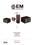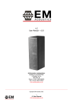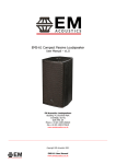
1
i-Series Subwoofers
User Manual – v3.0
i-8 compact compound isobaric subwoofer
i-12 compound isobaric ULF subwoofer
EM Acoustics Loudspeakers
Building 74, Dunsfold Park
Cranleigh, Surrey
GU6 8TB, UK
Phone +44 (0) 1483 266520
Fax +44 (0) 1483 275619
www.emacoustics.co.uk
_________________________________________________________________________________________
Copyright EM Acoustics 2010
1
i-Series Subwoofers User Manual
www.emacoustics.co.uk
CONTENTS
Introduction
Thank you
Page 3
Unpacking
Page 3
Declaration of Conformity
Page 3
Product Overview
Page 4
System Set-up
Safety Considerations
Page 6
Cabling & Amplifier selection
Page 6
i-12 impedance selection
Page 7
Processing
Page 8
Mounting & Rigging Options
Ground Stacking
Page 9
Rigging Hardware & Accessories
Page 9
Permanent Installations
Page 9
Maintenance
Page 10
Warranty
Page 12
Appendix A – Technical Specifications
Page 13
THIS MANUAL HAS BEEN UPDATED TO APPLY TO ALL i-12 SUBWOOFERS, and i-8
SUBWOOFERS FROM SERIAL NUMBER i8071112/001 ONWARDS.
2
i-Series Subwoofers User Manual
www.emacoustics.co.uk
INTRODUCTION
Thank you
Thank you for purchasing a product from the i-Series from EM Acoustics.
The i-Series products have been
carefully designed and rigorously tested to ensure years of flawless operation and unprecedented sonic quality.
Designed primarily for discreet installation use, the i-Series products find applications from cafes and bars through
to museums, nightclub infills and themed attractions.
Please ensure that you read this manual carefully before use, and that you keep it to hand should you need it for
further reference. Furthermore, should you have any difficulties please do not hesitate in contacting your EM
Acoustics dealer, or email [email protected] for further assistance.
Unpacking
Every EM Acoustics product is built to the highest standard and thoroughly tested before it leaves our factory.
After unpacking your loudspeaker, please inspect it carefully for any signs of transit damage. If such damage is
found, please notify the carrier at once to instigate a claim. It is suggested that you retain all packaging for future
re-shipment.
DECLARATION OF CONFORMITY
The products contained within this manual conform to the requirements of the EMC
Directive 89/336/EEC, amended by 92/31/EEC and to the requirements of the Low
Voltage Directive 73/23/EEC amended by 93/68/EEC.
Standards Applied:
EMC
Electrical Safety
Emission
EN55103-1:1996
Immunity
EN55103-2:1996
EN60065:1993
RECYCLING
This product and its packaging constitute the applicable product according to the WEEE directive.
Please ensure that at the end of the working life of this product, it is disposed of sensibly in
accordance with local and national recycling regulations. The packaging supplied with this product
is recyclable. Please retain all packaging, however if disposing of this packaging please ensure
that you comply with local recycling regulations. These products also all comply to the RoHS
Directive 2002/95/EC.
3
i-Series Subwoofers User Manual
www.emacoustics.co.uk
PRODUCT OVERVIEW
i-8 compact compound isobaric subwoofer
The i-8 is a subwoofer designed to create the depth and authority in low frequencies that is normally associated
with large systems, but in a compact package for ease of installation. Consequently, the i-8 has a frequency
response down to 35Hz yet is small enough to be concealed underneath sofas or in small wall cavities. The i-8 although small in size – has enough SPL output to be of use for nightclub or corporate applications, and even for
small FOH systems underneath EMS-81 enclosures. The i-8 subwoofer houses four 8” (203mm) long excursion low
frequency drive units, arranged as two isobaric pairs. This loading allows the enclosure to reproduce frequencies
not normally achieved from an enclosure of this size.
The enclosure is fitted with sixteen M10 threaded fixings, to allow overhead suspension in applications where floor
space is not available. Standard connectors for the i-8 are Neutrik SpeakonTM NL4MP, although alternatives can be
supplied on request.
As with all EM Acoustics products, no external equalisation is necessary to get the enclosure to perform as
specified. An active low pass filter is however required below 150Hz for correct operation, and for drive unit
protection a high pass filter is recommended – please see the processing section of this manual for more
information.
4
i-Series Subwoofers User Manual
www.emacoustics.co.uk
i-12 compound isobaric ULF subwoofer
The i-12 is the bigger brother of the i-8, and utilises the same enclosure technology.
Four high power, long
excursion 12” (305mm) drive units are contained within the compact enclosure, again arranged in a compound
isobaric format. This loading allows the i-12 to effortlessly reproduce frequencies as low as 27Hz, with more SPL
available than the smaller i-8.
This makes the i-12 the ideal theatrical effects subwoofer system, or an ideal
companion to the EMS-215 dual 15” subwoofer system where extra depth of response is required.
The enclosure comes supplied with steel bar handles as standard and there is an optional transit wheelboard and
protective cover. The i-12 is fitted with Neutrik SpeakonTM connectors as standard.
As with all EM Acoustics products, no external equalisation is necessary to get the enclosure to perform as
specified. An active low pass filter is however required below 100Hz for correct operation, and for drive unit
protection a high pass filter is recommended – please see the processing section of this manual for more
information.
5
i-Series Subwoofers User Manual
www.emacoustics.co.uk
SYSTEM SET-UP
Safety Considerations
Loudspeaker systems are potentially dangerous objects if used incorrectly.
Please ensure that you read this
section fully, and contact EM Acoustics or your local dealer should you be in any doubt over correct operation
procedures.
Professional loudspeaker systems are capable of producing damage-inducing sound pressure levels, and hence
care should be taken when setting your system up, particularly when it comes to loudspeaker placement within a
venue. Damage to the ear can result from levels above 90dB under prolonged exposure.
Cabling and Amplifier Selection
The i-Series products are designed to be used with professional power amplifiers providing the following power
outputs:
i-8
600W/channel into four ohms
i-12
2000W/channel into two ohms OR 1000W/channel into four ohms (dual 4-ohm mode)
It is good practice to use an amplifier with a power equal to the program power rating of the loudspeaker – so as
to retain sufficient headroom and good dynamic range. Care should be taken during operation to avoid amplifier
clipping – as this can cause serious damage to your loudspeakers. If in doubt, please contact your dealer who will
be happy to assist you in correct amplifier choice and setup.
A small power amplifier working too hard is more likely to damage a loudspeaker than a large power amplifier
working within its operating range!
6
i-Series Subwoofers User Manual
www.emacoustics.co.uk
Cabling
i-8 & i-12 subwoofers are supplied with Neutrik SpeakonTM NL4 connectors, wired on pins 1+/1-. The 2+/2- pins
are connected to allow link-through with four core cables (also for use on the i-12 in dual-channel mode – see
page 8 for details). It is recommended that the resistance of your cable is less than one tenth of the nominal
system impedance. Given below are the recommended maximum cable lengths for different cross-sections and
impedances.
Conductor Cross Sectional Area
Maximum Recommended Cable Length
4 ohms
8 ohms
16 ohms
2
11m
22m
44m
1.5mm2
17m
34m
68m
2.0mm
2
22m
44m
88m
2.5mm
2
29m
58m
116m
4.0mm
2
44m
88m
176m
6.0mm
2
66m
132m
264m
1.0mm
i-12 – Impedance Selection
A recessed switch on the rear of the i-12 allows the user to select the impedance of the enclosure. Some
amplifiers are not capable of driving 2-ohm loads, and as such the i-12 can be set to a dual 4-ohm load if required.
In this form of operation, one drive unit pair is on pins 1+/1- and the other pair is on pins 2+/2-.
NOTE – when using dual 4-ohm operation, ensure your cable polarity is correct as severe damage can
occur if the two driver pairs are out of phase. If in doubt, check with very low level initially.
With the switch in the 2-ohm position, all four drivers are connected to pins 1+/1- and pins 2+/2- are connected to
allow link-through.
7
i-Series Subwoofers User Manual
www.emacoustics.co.uk
Processing
i-Series subwoofers have no internal circuitry, and as such active crossover units are required to prevent damage
to your subwoofers. Low pass filters are required to prevent your low frequency reproduction sounding too “busy”
(and excessive high frequency will damage your subwoofers) and high pass filters are recommended to protect the
drive units from over-excursion.
i-8 subwoofer:
It is recommended that a high pass filter at 35Hz is used for moderate-to-high SPL applications to prevent the
drive units from over-excursion. Low pass filters can be set to personal taste – although it is recommended that
the filter is set below 150Hz. A minimum of 24dB/Octave slopes should be used – and faster slopes for the high
pass filter if possible.
i-12 subwoofer:
It is recommended that a high pass filter at 26Hz is used for moderate-to-high SPL applications to prevent the
drive units from over-excursion. Low pass filters can be set to personal taste – although it is recommended that
the filter is set below 100Hz. A minimum of 24dB/Octave slopes should be used – and faster slopes for the high
pass filter if possible.
If you are in any doubt whatsoever over correct processor settings, please do not hesitate to contact your EM
Acoustics representative or contact us at the factory directly.
8
i-Series Subwoofers User Manual
www.emacoustics.co.uk
MOUNTING & RIGGING OPTIONS
Ground Stacking
Ensure that the floor or stage surface can withstand the weight of the system.
Wherever possible, avoid high stacks and use ratchet straps to secure loudspeakers together. Please also
remember that vibrations from subwoofer systems can shake other loudspeakers out of place, which may
present a toppling hazard. The use of ratchet straps and non-slip material is recommended to prevent this.
Rigging and Suspension
WARNING: The overhead suspension of loudspeakers is a very serious issue with potentially lethal
consequences should anything go wrong.
Rigging should only be carried out by experienced
personnel following safe working practice. Should you be in any doubt whatsoever, please contact
your local dealer who will be able to refer you to a suitable rigging company.
Rigging Hardware & Accessories
The i-8 contains sixteen M10 threaded fixings around the enclosure, to enable suspension using forged shoulder
eyebolts with a minimum thread length of 20mm. With any suspension method, a second anchor point should be
used as a safety. The i-12 has no dedicated rigging options, as it is designed to be ground stacked only. If you
have any special requirements, please contact your local EM Acoustics representative or else email
[email protected] with your enquiry.
Under no circumstances should the mounting points of one enclosure be used to suspend another
enclosure below it.
EM Acoustics are in no way responsible for the failure of incorrectly rigged
systems. This information relates specifically to the rigging techniques for the i-Series enclosures
only. If you are in any doubt about safe practices for rigging loudspeakers, please contact your local
EM Acoustics dealer who will be able to advise you.
Permanent Installations
Any installation (permanent or temporary) must be securely attached to the structure of the building using chain,
steel wire or web straps that are certified and load rated for the loudspeaker system. Consideration must be taken
when determining the loading on the structure to include loudspeakers and rigging hardware, and the appropriate
safety factor can then be decided upon.
If you are in any doubt whatsoever, please contact your EM
Acoustics dealer who will be able to refer you to an experienced rigging company. A reputable rigging organisation
should also be able to advise on legislation regarding safety factors for suspended systems of this type.
9
i-Series Subwoofers User Manual
www.emacoustics.co.uk
MAINTENANCE
Your EM Acoustics loudspeakers have been rigorously tested before they leave our factory, to ensure that they give
you a lifetime of flawless operation. Should any of your drive units fail and need replacing, please follow the
guidelines below.
i-8: Front Low Frequency Drive Units
1. Carefully remove the foam from the grilles – it is held in place with Velcro fasteners. Using a No.2 Pozidrive
screwdriver, undo the four Pozidrive screws holding each grille in place, then remove the grilles to gain access
to the drive units.
2. Using a 10mm socket, undo the four M6 Nyloc nuts holding the drive unit in place. Disconnect the cables, and
lift the drive unit clear – ensuring to retain the four nuts, eight washers (shakeproof and flat for each bolt) and
the four speaker clamps for future reinstatement.
3. To reinstate the drive unit, carefully place it into the locating slot, then simply reverse the above procedure.
Please observe the correct (yet unusual) polarity – red cable to negative terminal, black cable to
positive. If using a new replacement drive unit, ensure that you attach the strip of self-adhesive gasket
around the inside of the chassis mounting flange, as this ensures an air-tight seal. The gasket needs to be cut
to length as it is supplied oversized.
4. Reinstate the grille and re-screw in place before sticking the foam back down.
i-8: Rear Low Frequency Drive Units
1. Follow the procedure above to remove the required front drive units.
2. Using a 3mm Allen key, undo the M5 countersunk machine screws holding the rear door in place. Remove this
door and carefully disconnect the crimp connectors from the spade terminals on the NL4 connectors.
3. Using a 10mm socket, undo the four M6 hex head bolts holding the drive unit in place. Disconnect the cables,
and lift the drive unit clear – ensuring to retain the four bolts, eight washers (shakeproof and flat for each bolt)
and the four speaker clamps for future reinstatement.
4.
To reinstate the drive unit, carefully place it into the locating slot, then simply reverse the above procedure.
Please observe the correct polarity – red cable to positive terminal, black cable to negative – and
observe that this is different to the front pair of drive units. If using a new replacement drive unit, ensure that
you attach the strip of self-adhesive gasket around the inside of the chassis mounting flange, as this ensures
an air-tight seal. The gasket needs to be cut to length as it is supplied oversized.
5. Re-attach the crimp connectors to the NL4 spades (red cable to 1+, black cable to 1-) and screw the door back
down again, ensuring that the door sits flush with the rear of the enclosure.
10
i-Series Subwoofers User Manual
www.emacoustics.co.uk
i-12: Front Low Frequency Drive Units
1. Carefully remove the foam from the grilles – it is held in place with Velcro fasteners. Using a No.2 Pozidrive
screwdriver, undo the Pozidrive screws holding each grille in place, then remove the grilles to gain access to
the drive units.
2. Using a 10mm socket, undo the four M6 Nyloc nuts holding the drive unit in place. Disconnect the cables, and
lift the drive unit clear – ensuring to retain the four nuts, eight washers (shakeproof and flat for each bolt) and
the four speaker clamps for future reinstatement.
3. To reinstate the drive unit, carefully place it into the locating slot, then simply reverse the above procedure.
Please observe the correct (yet unusual) polarity – red cable to negative terminal, black cable to
positive.
4. Reinstate the grille and re-screw in place before sticking the foam back down.
i-12: Rear Low Frequency Drive Units
1. Follow the procedure above to remove the required front drive units – the rear units cannot be removed with
the front units still in place.
2. Using a 3mm Allen key, undo the M5 countersunk machine screws holding the rear door in place. Remove this
door and carefully disconnect the crimp connectors from the spade terminals on the NL4 connectors.
3. Using a 10mm socket, undo the four M6 hex head bolts holding the drive unit in place. Disconnect the cables,
and lift the drive unit clear – ensuring to retain the four bolts, eight washers (shakeproof and flat for each bolt)
and the four speaker clamps for future reinstatement.
4.
To reinstate the drive unit, carefully place it into the locating slot, then simply reverse the above procedure.
Please observe the correct polarity – red cable to positive terminal, black cable to negative – and
observe that this is different to the front pair of drive units.
5. Re-attach the crimp connectors to the NL4 spades (red cable to 1+, black cable to 1-) and screw the door back
down again, ensuring that the door sits flush with the rear of the enclosure.
11
i-Series Subwoofers User Manual
www.emacoustics.co.uk
WARRANTY
Limited Warranty
This EM Acoustics loudspeaker product is warranted to the original end-user purchaser and all subsequent owners
for a period of three years from the original date of purchase.
Warranty Coverage
This warranty covers defects in materials and workmanship. It does not include:
Damage or failure caused by accident, misuse, neglect, abuse or modification by any person other than an
authorised EM Acoustics representative.
Damage or failure caused by operating the loudspeaker product contrary to the instructions contained within
this manual.
Damage caused during shipment.
Claims based on any misrepresentation by the seller.
Products which contain anything other than the original components (or EM Acoustics factory supplied spare
parts).
Products on which the serial number has been removed, altered or defaced.
Returning your EM Acoustics loudspeaker
Should your EM Acoustics loudspeaker develop a fault, please return it (freight prepaid) in its original packaging,
along with proof of purchase to your local dealer or to:
EM Acoustics (Returns Department), Building 74, Dunsfold Park, Cranleigh, Surrey, GU6 8TB, UK
including a description of the suspected fault. Serial numbers must be quoted in all correspondence relating to the
claim. EM Acoustics or its representatives are in no way liable for any loss or damage in transit, and hence it is
recommended that the sender insure the shipment. EM Acoustics will pay for return freight should the repair be
covered under warranty.
EM Acoustics’ liability is to the replacement or repair (at our discretion) of any defective components, and as such
are not liable for any incidental and consequential damages including (without limitation) injury to persons,
damage to property or loss of use.
This warranty is exclusive and no other warranty is expressed or implied. This warranty is also in
addition to – and in no way detracts from – your statutory rights as a consumer.
12
i-Series Subwoofers User Manual
www.emacoustics.co.uk
APPENDIX A – TECHNICAL SPECIFICATIONS
EM Acoustics operates a continuous process of research and development, and as such reserves the right to alter specifications without notice.
i-8
Enclosure Type:
compound isobaric subwoofer
Dimensions (HxWxD, mm/ins):
308/12.1 x 530/20.9 x 450/17.7
Net Weight:
22kg
Frequency Response (+/- 3dB):
35Hz – 150Hz
Sensitivity:
93dB, 1W/1m
Drive Units:
4 x 8” (203mm) LF cone drive units
Power Handling:
600W RMS, 1200W Program
Maximum SPL:
122dB continuous, 128dB peak
Nominal Impedance:
4 ohms
Crossover:
Active, recommended below 125Hz
Connectors:
2 x Neutrik SpeakonTM NL4MP
Enclosure:
15mm (5/8”) Finnish Birch plywood
Rigging/Suspension:
16 x M10 threaded fittings
Grille:
Acoustically transparent black foam on perforated steel
Options:
Colours/Weather Protection
Connectors
Spares & Accessories:
DU-806 replacement LF drive unit
RK-806 re-cone kit for DU-803
RFG-i8 replacement foam/grille pair
13
i-Series Subwoofers User Manual
www.emacoustics.co.uk
i-12
Enclosure Type:
compound isobaric subwoofer
Dimensions (HxWxD, mm/ins):
420/16.5 x 823/32.3 x 700/27.6
Net Weight:
83kg
Frequency Response (+/- 3dB):
27Hz – 100Hz
Sensitivity:
93dB, 1W/1m
Drive Units:
4 x 12” (305mm) LF cone drive units
Power Handling:
1000W RMS, 2000W Program
Maximum SPL:
128dB continuous, 136dB peak
Nominal Impedance:
2 ohms/2 x 4 ohms
Crossover:
Active, recommended below 100Hz
Connectors:
2 x Neutrik SpeakonTM NL4MP
Enclosure:
18mm (3/4”) Finnish Birch plywood
Grille:
Acoustically transparent black foam on perforated steel
Options:
Colours/Weather Protection
Spares & Accessories:
WB-i12 transit wheel board
TC-i12 padded transit cover
DU-1204 replacement LF drive unit
RK-1204 recone kit
RFG-i12 replacement foam/grille pair
14
i-Series Subwoofers User Manual
www.emacoustics.co.uk