1
QT-CD210/C
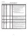
IC802 VHiTC9457F0-1: Servo/Signal Control (TC9457F0) (4/4)
Pin No.
Port Name
91
/HOLD
92
Terminal Name
Input/Output
Function
RYNCREC
Input
This pin is used to input a signal that requests or clears the hold mode.
Normally, use this pin for CD mode select signal input or battery detection
signal input.
There are two hold modes: clock stop mode (crystal oscillator turned off)
and a wait mode (CPU stopped). These modes are entered by executing
the CKSTP and WAIT instructions, respectively.
The clock stop mode can be requested by a programmed input: low level
detection on HOLD pin or forced execution, and can be cleared by
detecting a high on the HOLD pin or a change of state in its input signal.
When the CKSTP instruction is executed, the clock generator and the CPU
stop operating and the device is placed in a memory backup state. During
this state, the device's current consumption is reduced to 1µA or less.
At the same time, the display output and CMOS output ports are
automatically set low, and the Nch open-drain outputs are turned off.
The wait mode is executed regardles of the input state on the HOLD pin,
with the device's current consumption reduced.
This mode is cleared by a change of state in the HOLD input.
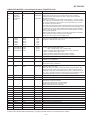
INTR
REMO-IN
Input
External interrupt input pin.
When the interrupt facility is enabled and a pulse of 1.11 to 2.22µs in
duration is applied to this pin, an interrupt is generated and the program
jumps to address 1. Input logic and the active edge (rise or fall) can be
selected for each interrupt input.
Also, the internal 8-bit time clock can be chosen for this interrupt input, in
which case it is possible to count pulses or generate an interrupt at a given
pulse count (address 3).
93*
94*
MXO
MXI
MXO
MXI
—
—
Crystal oscillator pins for the controller.
The oscillator clock is used as the timebase for the clock facility or as the
controller's system clock. Connect a 4.5MHz or 75kHz crystal resonator to
the MXO and MXI pins. Since these pins do not contain internal feedback
resistors, etc, an amp resistor or output resistor must be added external to
the chip.
When using the clock generated by the CD unit's crystal oscillator for
clocking the entire device operation, fix the MXI pin to the GND level.
Oscillation is stopped by executing a CKSTP instruction.
Select the crystal oscillator and control its operation by a program.
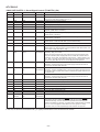
95
96
MVSS
MVDD
MVSS
MVDD
—
—
Power supply pins.
Normally, apply a voltage of 4.5 to 5.5V to VDD.
In a backup state (when the CKSTP instruction executed), the device's
current consumption is reduced to 1µA or less, allowing for the supply
voltage to be lowered to 2.0V.
The device is reset and the program starts from address 0 when a voltage
of 2.7V or more is applied to this pin when it is at 0V (power-on reset).
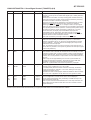
97
98
99
100
OT1
OT2
OT3
OT4
COM1
COM2
COM3
COM4
Output
Output
Output
Output
Common signal outputs to the LCD panel.
Up to 72 segments in a matrix with S1 to S18 can be displayed.
Three voltage levels MVDD, VEE (1/2 MVDD), and GND are output for
83Hz period at 2ms intervals.
After a system reset and after deassertion of a clock stop instruction, the
VEE voltage is output and the DISP OFF bit is set to 0 before common
signals are output.
In this unit, the terminal with asterisk mark (*) is (open) terminal which is not connected to the outside.
– 21 –