1
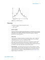
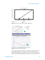
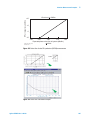
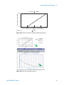
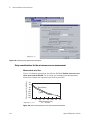
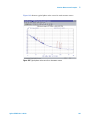
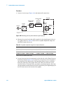
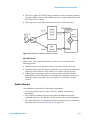
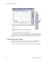
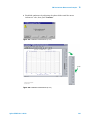
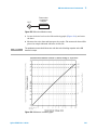
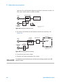
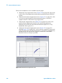
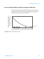
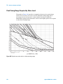
Figure 74. Reference source noise approaches DUT noise
111
Selecting a Reference 112
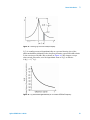
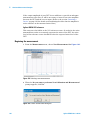
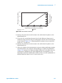
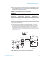
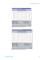
Figure 75. DUT noise approaches reference noise
112
Using a Similar Device
112
Using a Signal Generator
113
Tuning Requirements
113
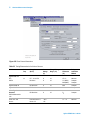
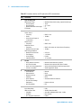
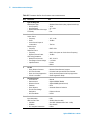
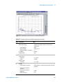
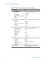
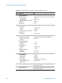
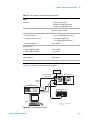
Table 12. Tuning Characteristics of Various VCO Source Options
113
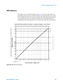
Figure 76. Voltage tuning range limits relative to center voltage of the VCO tuning
curve 114
Estimating the Tuning Constant
115
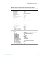
Table 13. VCO tuning constant calibration method
115
Tracking Frequency Drift
116
Evaluating beatnote drift
116
Changing the PTR 118
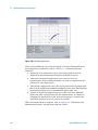
Figure 77. Peak tuning range
118
The Tuning Qualifications
118
Minimizing Injection Locking
120
Adding Isolation
120
Increasing the PLL Bandwidth 120
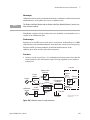
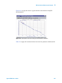
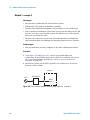
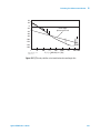
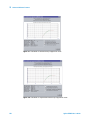
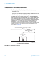
Figure 78. Peak tuning range (PTR) Required by injection locking.
121
Inserting a Device 122
An attenuator
122
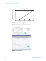
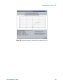
Figure 79. Measurement noise floor relative to R-Port signal level
122
An amplifier 123
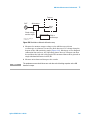
Figure 80. Measurement noise floor as a result of an added attenuator
123
Evaluating Noise Above the Small Angle Line
124
Determining the Phase-Lock-Loop bandwidth 124
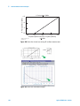
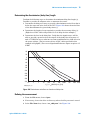
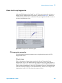
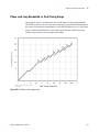
Figure 81. Phase lock loop bandwidth provided by the peak tuning range
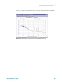
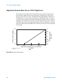
Figure 82. Graph of small angle line and spur limit
126
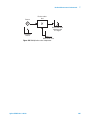
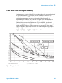
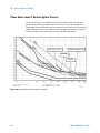
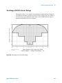
Figure 83. Requirements for noise exceeding small angle limit
127
6
125
Absolute Measurement Examples
Stable RF Oscillator
130
Required equipment
130
Defining the measurement
130
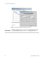
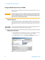
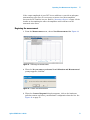
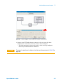
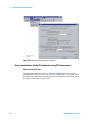
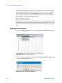
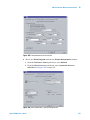
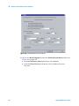
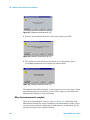
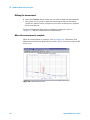
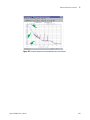
Figure 84. Select the parameters definition file
130
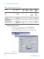
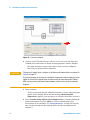
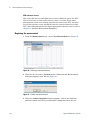
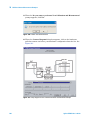
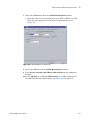
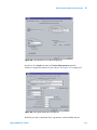
Figure 85. Enter source information 131
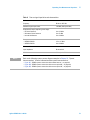
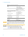
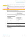
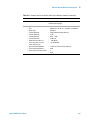
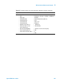
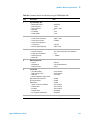
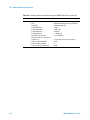
Table 14. Tuning characteristics for various sources
132
Selecting a reference source
132
Agilent E5505A User’s Guide
7