1
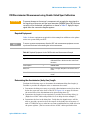
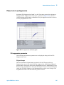
Absolute Measurement Examples
6
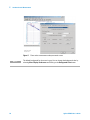
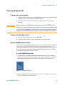
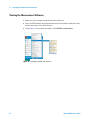
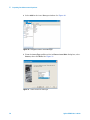
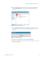
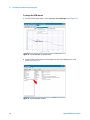
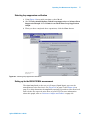
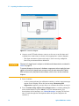
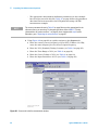
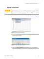
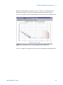
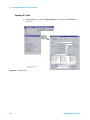
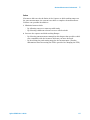
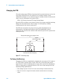
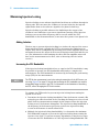
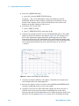
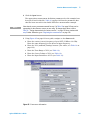
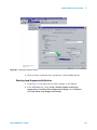
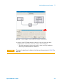
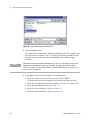
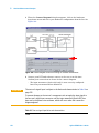
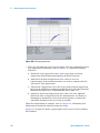
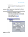
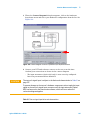
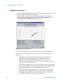
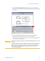
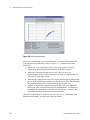
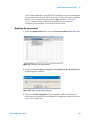
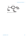
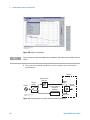
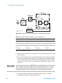
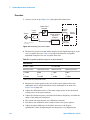
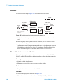
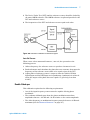
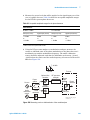
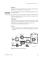
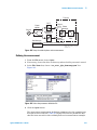
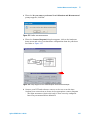
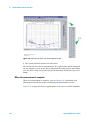
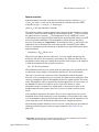
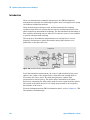
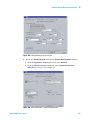
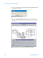
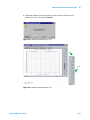
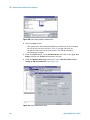
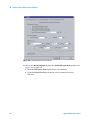
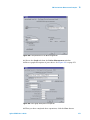
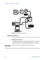
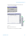
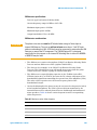
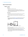
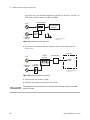
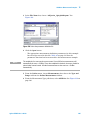
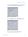
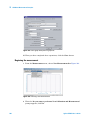
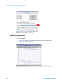
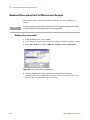
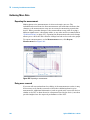
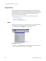
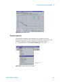
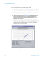
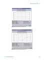
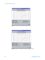
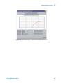
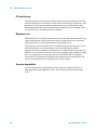
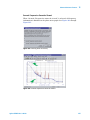
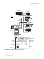
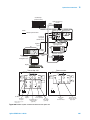
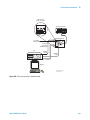
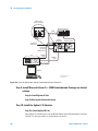
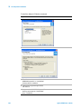
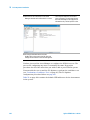
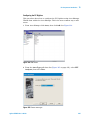
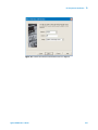
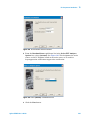
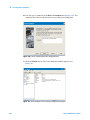
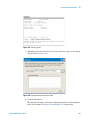
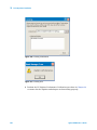
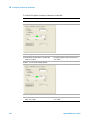
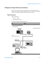
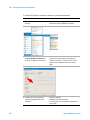
3 When the Connect Diagram dialog box appears, click on the hardware
drop-down arrow and select your hardware configuration from the list. See
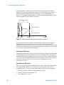
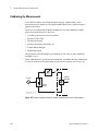
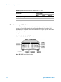
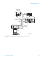
Figure 128.
N5500A
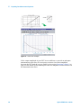
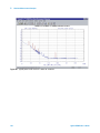
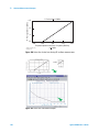
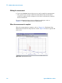
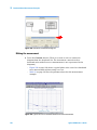
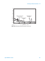
Figure 128 Connect diagram for the RF synthesizer (EFC) measurement
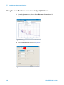
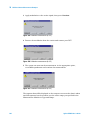
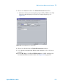
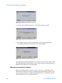
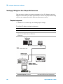
4 Connect your DUT and reference sources to the test set at this time.
Confirm your connections as shown in the connect diagram.
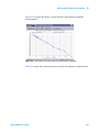
• The input attenuator (Option 001 only) is now correctly configured based
on your measurement definition.
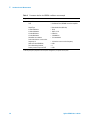
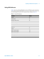
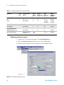
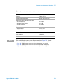
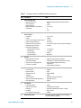
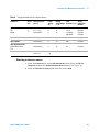
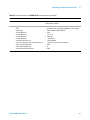
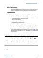
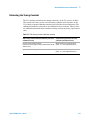
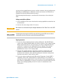
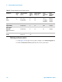
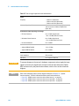
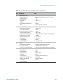
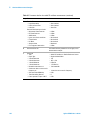
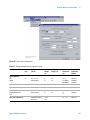
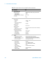
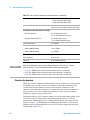
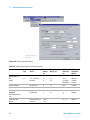
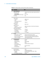
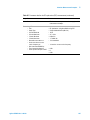
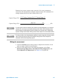
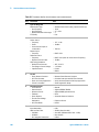
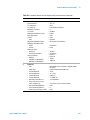
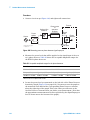
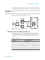
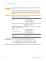
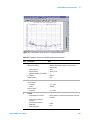
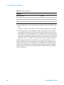
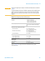
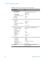
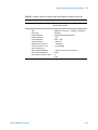
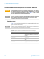
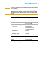
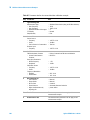
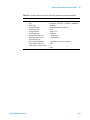
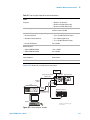
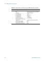
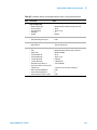
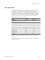
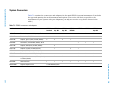
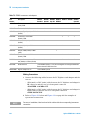
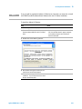
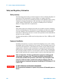
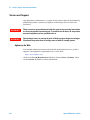
The test set’s signal input is subject to the limits and characteristics in Table 24 on
page 182.
A
C AU T I O N
To prevent damage to the test set’s hardware components, do not apply the input
signal to the test set’s signal input connector until the input attenuator (Option
001) has been set by the phase noise software, which will occur when the
connection diagram appears.
Agilent E5505A User’s Guide
181