1
Mitel 6800i Series SIP IP Phones
Administrator Guide
Release 4.0.0
41-001561-00 REV00 – 10.2014
Software License Agreement
Mitel, hereinafter known as "Seller", grants to Customer a personal, worldwide, non-transferable, non-sublicenseable and
non-exclusive, restricted use license to use Software in object form solely with the Equipment for which the Software
was intended. This Product may integrate programs, licensed to Mitel by third party Suppliers, for distribution under the
terms of this agreement. These programs are confidential and proprietary, and are protected as such by copyright law as
unpublished works and by international treaties to the fullest extent under the applicable law of the jurisdiction of the
Customer. In addition, these confidential and proprietary programs are works conforming to the requirements of Section 401 of title 17 of the United States Code. Customer shall not disclose to any third party such confidential and proprietary programs and information and shall not export licensed Software to any country except in accordance with United
States Export laws and restrictions.
Customer agrees to not reverse engineer, decompile, disassemble or display Software furnished in object code form.
Customer shall not modify, copy, reproduce, distribute, transcribe, translate or reduce to electronic medium or machine
readable form or language, derive source code without the express written consent of the Seller and its Suppliers, or disseminate or otherwise disclose the Software to third parties. All Software furnished hereunder (whether or not part of
firmware), including all copies thereof, are and shall remain the property of Seller and its Suppliers and are subject to the
terms and conditions of this agreement. All rights reserved.
Customer's use of this software shall be deemed to reflect Customer's agreement to abide by the terms and conditions
contained herein. Removal or modification of trademarks, copyright notices, logos, etc., or the use of Software on any
Equipment other than that for which it is intended, or any other material breach of this Agreement, shall automatically
terminate this license. If this Agreement is terminated for breach, Customer shall immediately discontinue use and
destroy or return to Seller all licensed software and other confidential or proprietary information of Seller. In no event
shall Seller or its suppliers or licensors be liable for any damages whatsoever (including without limitation, damages for
loss of business profits, business interruption, loss of business information, other pecuniary loss, or consequential damages) arising out of the use of or inability to use the software, even if Seller has been advised of the possibility of such
damages.
ii
41-001561-00 REV00 – 10.2014
Content
Software License Agreement . . . . . . . . . . . . . . . . . . . . . . . . . . . . . . . . . . . . . . . . . . . . . . . . . . . . . . . . . . . . . . . . . . . . . . . . .ii
Preface . . . . . . . . . . . . . . . . . . . . . . . . . . . . . . . . . . . . . . . . . . . . . . . . . . . . . . . . . . . . . . . . . . . . . . . . . . . . . . . . . . . . . . . . . . . . . . . . . . . . . xviii
Audience . . . . . . . . . . . . . . . . . . . . . . . . . . . . . . . . . . . . . . . . . . . . . . . . . . . . . . . . . . . . . . . . . . . . . . . . . . . . . . . . . . . . . . . . . . . . . . . . xviii
Documentation . . . . . . . . . . . . . . . . . . . . . . . . . . . . . . . . . . . . . . . . . . . . . . . . . . . . . . . . . . . . . . . . . . . . . . . . . . . . . . . . . . . . . . . . . xviii
Chapters and Appendices in this Guide . . . . . . . . . . . . . . . . . . . . . . . . . . . . . . . . . . . . . . . . . . . . . . . . . . . . . . . . . . . . . . . . . . . xix
Chapter 1:
Overview . . . . . . . . . . . . . . . . . . . . . . . . . . . . . . . . . . . . . . . . . . . . . . . . . . . . . . . . . . . . . . . . . . . . . . . . . . . . . . . . . . . . . . . . . . . . . . . . . . .1-1
About this Chapter . . . . . . . . . . . . . . . . . . . . . . . . . . . . . . . . . . . . . . . . . . . . . . . . . . . . . . . . . . . . . . . . . . . . . . . . . . . . . . . . . . . . . .1-1
Topics . . . . . . . . . . . . . . . . . . . . . . . . . . . . . . . . . . . . . . . . . . . . . . . . . . . . . . . . . . . . . . . . . . . . . . . . . . . . . . . . . . . . . . . . . . . . . . . . . . . .1-1
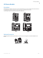
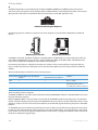
IP Phone Models . . . . . . . . . . . . . . . . . . . . . . . . . . . . . . . . . . . . . . . . . . . . . . . . . . . . . . . . . . . . . . . . . . . . . . . . . . . . . . . . . . . . . . . . .1-2
Description. . . . . . . . . . . . . . . . . . . . . . . . . . . . . . . . . . . . . . . . . . . . . . . . . . . . . . . . . . . . . . . . . . . . . . . . . . . . . . . . . . . . . . . . . . . . . . .1-2
Optional Accessories . . . . . . . . . . . . . . . . . . . . . . . . . . . . . . . . . . . . . . . . . . . . . . . . . . . . . . . . . . . . . . . . . . . . . . . . . . . . . . . . . . . . .1-2
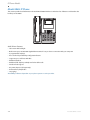
Model 6863i IP Phone . . . . . . . . . . . . . . . . . . . . . . . . . . . . . . . . . . . . . . . . . . . . . . . . . . . . . . . . . . . . . . . . . . . . . . . . . . . . . . . . . . . .1-5
Model 6865i IP Phone . . . . . . . . . . . . . . . . . . . . . . . . . . . . . . . . . . . . . . . . . . . . . . . . . . . . . . . . . . . . . . . . . . . . . . . . . . . . . . . . . . . .1-7
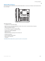
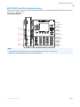
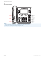
Model 6867i IP Phone . . . . . . . . . . . . . . . . . . . . . . . . . . . . . . . . . . . . . . . . . . . . . . . . . . . . . . . . . . . . . . . . . . . . . . . . . . . . . . . . . . 1-10
Model 6869i IP Phone . . . . . . . . . . . . . . . . . . . . . . . . . . . . . . . . . . . . . . . . . . . . . . . . . . . . . . . . . . . . . . . . . . . . . . . . . . . . . . . . . . 1-13
Firmware Installation Information . . . . . . . . . . . . . . . . . . . . . . . . . . . . . . . . . . . . . . . . . . . . . . . . . . . . . . . . . . . . . . . . . 1-16
Description. . . . . . . . . . . . . . . . . . . . . . . . . . . . . . . . . . . . . . . . . . . . . . . . . . . . . . . . . . . . . . . . . . . . . . . . . . . . . . . . . . . . . . . . . . . . . 1-16
Installation Considerations. . . . . . . . . . . . . . . . . . . . . . . . . . . . . . . . . . . . . . . . . . . . . . . . . . . . . . . . . . . . . . . . . . . . . . . . . . . . . 1-16
Installation Requirements . . . . . . . . . . . . . . . . . . . . . . . . . . . . . . . . . . . . . . . . . . . . . . . . . . . . . . . . . . . . . . . . . . . . . . . . . . . . . . 1-16
Configuration Server Requirement . . . . . . . . . . . . . . . . . . . . . . . . . . . . . . . . . . . . . . . . . . . . . . . . . . . . . . . . . . . . . . . . . . . . . 1-16
Firmware and Configuration Files . . . . . . . . . . . . . . . . . . . . . . . . . . . . . . . . . . . . . . . . . . . . . . . . . . . . . . . . . . . . . . . . . . 1-17
Description. . . . . . . . . . . . . . . . . . . . . . . . . . . . . . . . . . . . . . . . . . . . . . . . . . . . . . . . . . . . . . . . . . . . . . . . . . . . . . . . . . . . . . . . . . . . . 1-17
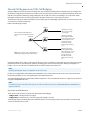
Configuration File Precedence. . . . . . . . . . . . . . . . . . . . . . . . . . . . . . . . . . . . . . . . . . . . . . . . . . . . . . . . . . . . . . . . . . . . . . . . . . 1-18
Installing the Firmware/Configuration Files . . . . . . . . . . . . . . . . . . . . . . . . . . . . . . . . . . . . . . . . . . . . . . . . . . . . . . . . . . . . 1-18
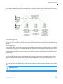
Multiple Configuration Server Support . . . . . . . . . . . . . . . . . . . . . . . . . . . . . . . . . . . . . . . . . . . . . . . . . . . . . . . . . . . . . . . . . 1-19
41-001561-00 REV00 – 10.2014
iii
Content
Chapter 2:
Configuration Interface Methods
. . . . . . . . . . . . . . . . . . . . . . . . . . . . . . . . . . . . . . . . . . . . . . . . . . . . . . . . . . . . . . . .2-1
About this Chapter . . . . . . . . . . . . . . . . . . . . . . . . . . . . . . . . . . . . . . . . . . . . . . . . . . . . . . . . . . . . . . . . . . . . . . . . . . . . . . . . . . . . . .2-1
Topics . . . . . . . . . . . . . . . . . . . . . . . . . . . . . . . . . . . . . . . . . . . . . . . . . . . . . . . . . . . . . . . . . . . . . . . . . . . . . . . . . . . . . . . . . . . . . . . . . . . .2-1
Configuration Methods . . . . . . . . . . . . . . . . . . . . . . . . . . . . . . . . . . . . . . . . . . . . . . . . . . . . . . . . . . . . . . . . . . . . . . . . . . . . . . . .2-2
Description. . . . . . . . . . . . . . . . . . . . . . . . . . . . . . . . . . . . . . . . . . . . . . . . . . . . . . . . . . . . . . . . . . . . . . . . . . . . . . . . . . . . . . . . . . . . . . .2-2
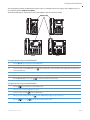
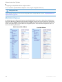
IP Phone UI . . . . . . . . . . . . . . . . . . . . . . . . . . . . . . . . . . . . . . . . . . . . . . . . . . . . . . . . . . . . . . . . . . . . . . . . . . . . . . . . . . . . . . . . . . . . . . .2-2
Mitel Web UI. . . . . . . . . . . . . . . . . . . . . . . . . . . . . . . . . . . . . . . . . . . . . . . . . . . . . . . . . . . . . . . . . . . . . . . . . . . . . . . . . . . . . . . . . . . . . .2-4
Configuration Files (Administrator Only) . . . . . . . . . . . . . . . . . . . . . . . . . . . . . . . . . . . . . . . . . . . . . . . . . . . . . . . . . . . . . . . 2-11
Chapter 3:
Administrator Options
. . . . . . . . . . . . . . . . . . . . . . . . . . . . . . . . . . . . . . . . . . . . . . . . . . . . . . . . . . . . . . . . . . . . . . . . . . . . . . .3-1
About this Chapter . . . . . . . . . . . . . . . . . . . . . . . . . . . . . . . . . . . . . . . . . . . . . . . . . . . . . . . . . . . . . . . . . . . . . . . . . . . . . . . . . . . . . .3-1
Topics . . . . . . . . . . . . . . . . . . . . . . . . . . . . . . . . . . . . . . . . . . . . . . . . . . . . . . . . . . . . . . . . . . . . . . . . . . . . . . . . . . . . . . . . . . . . . . . . . . . .3-1
Administrator Level Options . . . . . . . . . . . . . . . . . . . . . . . . . . . . . . . . . . . . . . . . . . . . . . . . . . . . . . . . . . . . . . . . . . . . . . . . . .3-2
Description. . . . . . . . . . . . . . . . . . . . . . . . . . . . . . . . . . . . . . . . . . . . . . . . . . . . . . . . . . . . . . . . . . . . . . . . . . . . . . . . . . . . . . . . . . . . . . .3-2
IP Phone UI Options . . . . . . . . . . . . . . . . . . . . . . . . . . . . . . . . . . . . . . . . . . . . . . . . . . . . . . . . . . . . . . . . . . . . . . . . . . . . . . . . . . . . . .3-2
Mitel Web UI Options . . . . . . . . . . . . . . . . . . . . . . . . . . . . . . . . . . . . . . . . . . . . . . . . . . . . . . . . . . . . . . . . . . . . . . . . . . . . . . . . . . . . .3-4
Configuration File Options . . . . . . . . . . . . . . . . . . . . . . . . . . . . . . . . . . . . . . . . . . . . . . . . . . . . . . . . . . . . . . . . . . . . . . . . . . . . . . .3-6
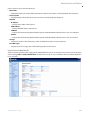
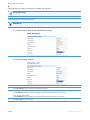
Phone Status . . . . . . . . . . . . . . . . . . . . . . . . . . . . . . . . . . . . . . . . . . . . . . . . . . . . . . . . . . . . . . . . . . . . . . . . . . . . . . . . . . . . . . . . . . . . .3-6
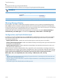
Restarting Your Phone . . . . . . . . . . . . . . . . . . . . . . . . . . . . . . . . . . . . . . . . . . . . . . . . . . . . . . . . . . . . . . . . . . . . . . . . . . . . . . . . . . .3-9
Set Phone to Factory Defaults/Erase Local Configuration . . . . . . . . . . . . . . . . . . . . . . . . . . . . . . . . . . . . . . . . . . . . . . . 3-10
Basic Settings . . . . . . . . . . . . . . . . . . . . . . . . . . . . . . . . . . . . . . . . . . . . . . . . . . . . . . . . . . . . . . . . . . . . . . . . . . . . . . . . . . . . . . . . . . 3-12
Account Configuration . . . . . . . . . . . . . . . . . . . . . . . . . . . . . . . . . . . . . . . . . . . . . . . . . . . . . . . . . . . . . . . . . . . . . . . . . . . . . . . . . 3-23
Custom Ringtones . . . . . . . . . . . . . . . . . . . . . . . . . . . . . . . . . . . . . . . . . . . . . . . . . . . . . . . . . . . . . . . . . . . . . . . . . . . . . . . . . . . . . . 3-24
Network Settings . . . . . . . . . . . . . . . . . . . . . . . . . . . . . . . . . . . . . . . . . . . . . . . . . . . . . . . . . . . . . . . . . . . . . . . . . . . . . . . . . . . . . . . 3-24
Line Settings . . . . . . . . . . . . . . . . . . . . . . . . . . . . . . . . . . . . . . . . . . . . . . . . . . . . . . . . . . . . . . . . . . . . . . . . . . . . . . . . . . . . . . . . . . . 3-40
Softkeys, Programmable Keys, Expansion Module Keys. . . . . . . . . . . . . . . . . . . . . . . . . . . . . . . . . . . . . . . . . . . . . . . . . 3-41
Action URI . . . . . . . . . . . . . . . . . . . . . . . . . . . . . . . . . . . . . . . . . . . . . . . . . . . . . . . . . . . . . . . . . . . . . . . . . . . . . . . . . . . . . . . . . . . . . . 3-41
Configuration Server Settings . . . . . . . . . . . . . . . . . . . . . . . . . . . . . . . . . . . . . . . . . . . . . . . . . . . . . . . . . . . . . . . . . . . . . . . . . . 3-43
Firmware Update Features . . . . . . . . . . . . . . . . . . . . . . . . . . . . . . . . . . . . . . . . . . . . . . . . . . . . . . . . . . . . . . . . . . . . . . . . . . . . . 3-46
TLS Support . . . . . . . . . . . . . . . . . . . . . . . . . . . . . . . . . . . . . . . . . . . . . . . . . . . . . . . . . . . . . . . . . . . . . . . . . . . . . . . . . . . . . . . . . . . . 3-47
802.1x Support . . . . . . . . . . . . . . . . . . . . . . . . . . . . . . . . . . . . . . . . . . . . . . . . . . . . . . . . . . . . . . . . . . . . . . . . . . . . . . . . . . . . . . . . . 3-49
Troubleshooting . . . . . . . . . . . . . . . . . . . . . . . . . . . . . . . . . . . . . . . . . . . . . . . . . . . . . . . . . . . . . . . . . . . . . . . . . . . . . . . . . . . . . . . 3-50
iv
41-001561-00 REV00 – 10.2014
Content
Chapter 4:
Configuring Network and Session Initiation Protocol (SIP) Features
. . . . . . . . . . . . . .4-1
About this Chapter . . . . . . . . . . . . . . . . . . . . . . . . . . . . . . . . . . . . . . . . . . . . . . . . . . . . . . . . . . . . . . . . . . . . . . . . . . . . . . . . . . . . . .4-1
Topics . . . . . . . . . . . . . . . . . . . . . . . . . . . . . . . . . . . . . . . . . . . . . . . . . . . . . . . . . . . . . . . . . . . . . . . . . . . . . . . . . . . . . . . . . . . . . . . . . . . .4-1
Overview . . . . . . . . . . . . . . . . . . . . . . . . . . . . . . . . . . . . . . . . . . . . . . . . . . . . . . . . . . . . . . . . . . . . . . . . . . . . . . . . . . . . . . . . . . . . . . . . . .4-2
References . . . . . . . . . . . . . . . . . . . . . . . . . . . . . . . . . . . . . . . . . . . . . . . . . . . . . . . . . . . . . . . . . . . . . . . . . . . . . . . . . . . . . . . . . . . . . . .4-2
Network Settings . . . . . . . . . . . . . . . . . . . . . . . . . . . . . . . . . . . . . . . . . . . . . . . . . . . . . . . . . . . . . . . . . . . . . . . . . . . . . . . . . . . . . . . .4-3
Basic Network Settings . . . . . . . . . . . . . . . . . . . . . . . . . . . . . . . . . . . . . . . . . . . . . . . . . . . . . . . . . . . . . . . . . . . . . . . . . . . . . . . . . . .4-3
Advanced Network Settings . . . . . . . . . . . . . . . . . . . . . . . . . . . . . . . . . . . . . . . . . . . . . . . . . . . . . . . . . . . . . . . . . . . . . . . . . . . . 4-22
Global SIP Settings . . . . . . . . . . . . . . . . . . . . . . . . . . . . . . . . . . . . . . . . . . . . . . . . . . . . . . . . . . . . . . . . . . . . . . . . . . . . . . . . . . . . 4-49
Description. . . . . . . . . . . . . . . . . . . . . . . . . . . . . . . . . . . . . . . . . . . . . . . . . . . . . . . . . . . . . . . . . . . . . . . . . . . . . . . . . . . . . . . . . . . . . 4-49
Basic SIP Settings. . . . . . . . . . . . . . . . . . . . . . . . . . . . . . . . . . . . . . . . . . . . . . . . . . . . . . . . . . . . . . . . . . . . . . . . . . . . . . . . . . . . . . . 4-49
Advanced SIP Settings (optional) . . . . . . . . . . . . . . . . . . . . . . . . . . . . . . . . . . . . . . . . . . . . . . . . . . . . . . . . . . . . . . . . . . . . . . . 4-63
Real-time Transport Protocol (RTP) Settings . . . . . . . . . . . . . . . . . . . . . . . . . . . . . . . . . . . . . . . . . . . . . . . . . . . . . . . . . . . . 4-68
RTCP Summary Reports . . . . . . . . . . . . . . . . . . . . . . . . . . . . . . . . . . . . . . . . . . . . . . . . . . . . . . . . . . . . . . . . . . . . . . . . . . . . . . . . 4-77
Autodial Settings . . . . . . . . . . . . . . . . . . . . . . . . . . . . . . . . . . . . . . . . . . . . . . . . . . . . . . . . . . . . . . . . . . . . . . . . . . . . . . . . . . . . . . . 4-77
Configuration Server Protocol . . . . . . . . . . . . . . . . . . . . . . . . . . . . . . . . . . . . . . . . . . . . . . . . . . . . . . . . . . . . . . . . . . . . . . 4-80
Configuring the Configuration Server Protocol . . . . . . . . . . . . . . . . . . . . . . . . . . . . . . . . . . . . . . . . . . . . . . . . . . . . . . . . . 4-80
Chapter 5:
Configuring Operational Features . . . . . . . . . . . . . . . . . . . . . . . . . . . . . . . . . . . . . . . . . . . . . . . . . . . . . . . . . . . . . . .5-1
About this Chapter . . . . . . . . . . . . . . . . . . . . . . . . . . . . . . . . . . . . . . . . . . . . . . . . . . . . . . . . . . . . . . . . . . . . . . . . . . . . . . . . . . . . . .5-1
Topics . . . . . . . . . . . . . . . . . . . . . . . . . . . . . . . . . . . . . . . . . . . . . . . . . . . . . . . . . . . . . . . . . . . . . . . . . . . . . . . . . . . . . . . . . . . . . . . . . . . .5-1
Operational Features . . . . . . . . . . . . . . . . . . . . . . . . . . . . . . . . . . . . . . . . . . . . . . . . . . . . . . . . . . . . . . . . . . . . . . . . . . . . . . . . . . .5-4
Description. . . . . . . . . . . . . . . . . . . . . . . . . . . . . . . . . . . . . . . . . . . . . . . . . . . . . . . . . . . . . . . . . . . . . . . . . . . . . . . . . . . . . . . . . . . . . . .5-4
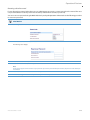
User Passwords . . . . . . . . . . . . . . . . . . . . . . . . . . . . . . . . . . . . . . . . . . . . . . . . . . . . . . . . . . . . . . . . . . . . . . . . . . . . . . . . . . . . . . . . . .5-4
Administrator Passwords. . . . . . . . . . . . . . . . . . . . . . . . . . . . . . . . . . . . . . . . . . . . . . . . . . . . . . . . . . . . . . . . . . . . . . . . . . . . . . . . .5-7
Locking/Unlocking the Phone . . . . . . . . . . . . . . . . . . . . . . . . . . . . . . . . . . . . . . . . . . . . . . . . . . . . . . . . . . . . . . . . . . . . . . . . . . . .5-7
Defining an Emergency Dial Plan . . . . . . . . . . . . . . . . . . . . . . . . . . . . . . . . . . . . . . . . . . . . . . . . . . . . . . . . . . . . . . . . . . . . . . . 5-11
Configurable Emergency Call Behavior . . . . . . . . . . . . . . . . . . . . . . . . . . . . . . . . . . . . . . . . . . . . . . . . . . . . . . . . . . . . . . . . . 5-14
User Dial Plan Setting . . . . . . . . . . . . . . . . . . . . . . . . . . . . . . . . . . . . . . . . . . . . . . . . . . . . . . . . . . . . . . . . . . . . . . . . . . . . . . . . . . 5-14
Time and Date. . . . . . . . . . . . . . . . . . . . . . . . . . . . . . . . . . . . . . . . . . . . . . . . . . . . . . . . . . . . . . . . . . . . . . . . . . . . . . . . . . . . . . . . . . 5-15
Backlight Mode . . . . . . . . . . . . . . . . . . . . . . . . . . . . . . . . . . . . . . . . . . . . . . . . . . . . . . . . . . . . . . . . . . . . . . . . . . . . . . . . . . . . . . . . 5-25
Display . . . . . . . . . . . . . . . . . . . . . . . . . . . . . . . . . . . . . . . . . . . . . . . . . . . . . . . . . . . . . . . . . . . . . . . . . . . . . . . . . . . . . . . . . . . . . . . . 5-26
41-001561-00 REV00 – 10.2014
v
Content
Background Image on Idle Screen . . . . . . . . . . . . . . . . . . . . . . . . . . . . . . . . . . . . . . . . . . . . . . . . . . . . . . . . . . . . . . . . . . . . . . 5-27
Configurable Home/Idle Screen Modes . . . . . . . . . . . . . . . . . . . . . . . . . . . . . . . . . . . . . . . . . . . . . . . . . . . . . . . . . . . . . . . . . 5-28
Configurable Home/Idle Screen Font Color . . . . . . . . . . . . . . . . . . . . . . . . . . . . . . . . . . . . . . . . . . . . . . . . . . . . . . . . . . . . . 5-29
Screen Saver . . . . . . . . . . . . . . . . . . . . . . . . . . . . . . . . . . . . . . . . . . . . . . . . . . . . . . . . . . . . . . . . . . . . . . . . . . . . . . . . . . . . . . . . . . . 5-29
Picture ID Feature . . . . . . . . . . . . . . . . . . . . . . . . . . . . . . . . . . . . . . . . . . . . . . . . . . . . . . . . . . . . . . . . . . . . . . . . . . . . . . . . . . . . . . 5-31
Audio DHSG Headset . . . . . . . . . . . . . . . . . . . . . . . . . . . . . . . . . . . . . . . . . . . . . . . . . . . . . . . . . . . . . . . . . . . . . . . . . . . . . . . . . . . 5-31
Audio Hi-Q on G.722 Calls . . . . . . . . . . . . . . . . . . . . . . . . . . . . . . . . . . . . . . . . . . . . . . . . . . . . . . . . . . . . . . . . . . . . . . . . . . . . . . 5-33
Audio Transmit and Receive Gain Adjustments . . . . . . . . . . . . . . . . . . . . . . . . . . . . . . . . . . . . . . . . . . . . . . . . . . . . . . . . . 5-34
Live Dialpad. . . . . . . . . . . . . . . . . . . . . . . . . . . . . . . . . . . . . . . . . . . . . . . . . . . . . . . . . . . . . . . . . . . . . . . . . . . . . . . . . . . . . . . . . . . . 5-35
Language . . . . . . . . . . . . . . . . . . . . . . . . . . . . . . . . . . . . . . . . . . . . . . . . . . . . . . . . . . . . . . . . . . . . . . . . . . . . . . . . . . . . . . . . . . . . . . 5-36
Minimum Ringer Volume . . . . . . . . . . . . . . . . . . . . . . . . . . . . . . . . . . . . . . . . . . . . . . . . . . . . . . . . . . . . . . . . . . . . . . . . . . . . . . . 5-47
Locking IP Phone Keys . . . . . . . . . . . . . . . . . . . . . . . . . . . . . . . . . . . . . . . . . . . . . . . . . . . . . . . . . . . . . . . . . . . . . . . . . . . . . . . . . . 5-47
Locking/Unlocking the SAVE and DELETE keys . . . . . . . . . . . . . . . . . . . . . . . . . . . . . . . . . . . . . . . . . . . . . . . . . . . . . . . . . . 5-48
Local Dial Plan . . . . . . . . . . . . . . . . . . . . . . . . . . . . . . . . . . . . . . . . . . . . . . . . . . . . . . . . . . . . . . . . . . . . . . . . . . . . . . . . . . . . . . . . . 5-50
Suppressing DTMF Playback. . . . . . . . . . . . . . . . . . . . . . . . . . . . . . . . . . . . . . . . . . . . . . . . . . . . . . . . . . . . . . . . . . . . . . . . . . . . 5-53
Display DTMF Digits . . . . . . . . . . . . . . . . . . . . . . . . . . . . . . . . . . . . . . . . . . . . . . . . . . . . . . . . . . . . . . . . . . . . . . . . . . . . . . . . . . . . 5-53
Filter Out Incoming DTMF Events . . . . . . . . . . . . . . . . . . . . . . . . . . . . . . . . . . . . . . . . . . . . . . . . . . . . . . . . . . . . . . . . . . . . . . . 5-54
Call Waiting . . . . . . . . . . . . . . . . . . . . . . . . . . . . . . . . . . . . . . . . . . . . . . . . . . . . . . . . . . . . . . . . . . . . . . . . . . . . . . . . . . . . . . . . . . . . 5-55
Stuttered Dial Tone. . . . . . . . . . . . . . . . . . . . . . . . . . . . . . . . . . . . . . . . . . . . . . . . . . . . . . . . . . . . . . . . . . . . . . . . . . . . . . . . . . . . . 5-59
XML Beep Support . . . . . . . . . . . . . . . . . . . . . . . . . . . . . . . . . . . . . . . . . . . . . . . . . . . . . . . . . . . . . . . . . . . . . . . . . . . . . . . . . . . . . . 5-60
Status Scroll Delay . . . . . . . . . . . . . . . . . . . . . . . . . . . . . . . . . . . . . . . . . . . . . . . . . . . . . . . . . . . . . . . . . . . . . . . . . . . . . . . . . . . . . 5-61
Switch Focus to Ringing Line. . . . . . . . . . . . . . . . . . . . . . . . . . . . . . . . . . . . . . . . . . . . . . . . . . . . . . . . . . . . . . . . . . . . . . . . . . . . 5-62
Call Hold Reminder During Active Calls . . . . . . . . . . . . . . . . . . . . . . . . . . . . . . . . . . . . . . . . . . . . . . . . . . . . . . . . . . . . . . . . . 5-63
Call Hold Reminder (on Single Hold) . . . . . . . . . . . . . . . . . . . . . . . . . . . . . . . . . . . . . . . . . . . . . . . . . . . . . . . . . . . . . . . . . . . . 5-64
Call Hold Reminder Timer & Frequency . . . . . . . . . . . . . . . . . . . . . . . . . . . . . . . . . . . . . . . . . . . . . . . . . . . . . . . . . . . . . . . . . 5-65
Preferred Line and Preferred Line Timeout. . . . . . . . . . . . . . . . . . . . . . . . . . . . . . . . . . . . . . . . . . . . . . . . . . . . . . . . . . . . . . 5-66
Goodbye Key Cancels Incoming Call . . . . . . . . . . . . . . . . . . . . . . . . . . . . . . . . . . . . . . . . . . . . . . . . . . . . . . . . . . . . . . . . . . . . 5-67
Message Waiting Indicator Line . . . . . . . . . . . . . . . . . . . . . . . . . . . . . . . . . . . . . . . . . . . . . . . . . . . . . . . . . . . . . . . . . . . . . . . . 5-69
Customizable Message Waiting Indicator (MWI) Request URI . . . . . . . . . . . . . . . . . . . . . . . . . . . . . . . . . . . . . . . . . . . 5-70
DND Key Mode . . . . . . . . . . . . . . . . . . . . . . . . . . . . . . . . . . . . . . . . . . . . . . . . . . . . . . . . . . . . . . . . . . . . . . . . . . . . . . . . . . . . . . . . . 5-71
Call Forward Mode . . . . . . . . . . . . . . . . . . . . . . . . . . . . . . . . . . . . . . . . . . . . . . . . . . . . . . . . . . . . . . . . . . . . . . . . . . . . . . . . . . . . . 5-73
Link Layer Discovery Protocol for Media Endpoint Devices (LLDP-MED)
and Emergency Location Identification Number (ELIN). . . . . . . . . . . . . . . . . . . . . . . . . . . . . . . . . . . . . . . . . . . . . . . . . . 5-75
Incoming/Outgoing Intercom with Auto-Answer and Barge In . . . . . . . . . . . . . . . . . . . . . . . . . . . . . . . . . . . . . . . . . . 5-77
vi
41-001561-00 REV00 – 10.2014
Content
Group Paging RTP Settings . . . . . . . . . . . . . . . . . . . . . . . . . . . . . . . . . . . . . . . . . . . . . . . . . . . . . . . . . . . . . . . . . . . . . . . . . . . . . 5-80
Speeddial Key Mapping . . . . . . . . . . . . . . . . . . . . . . . . . . . . . . . . . . . . . . . . . . . . . . . . . . . . . . . . . . . . . . . . . . . . . . . . . . . . . . . . 5-82
Send DTMF for Remapping Conference or Redial Key . . . . . . . . . . . . . . . . . . . . . . . . . . . . . . . . . . . . . . . . . . . . . . . . . . . 5-84
Ring Tones and Tone Sets. . . . . . . . . . . . . . . . . . . . . . . . . . . . . . . . . . . . . . . . . . . . . . . . . . . . . . . . . . . . . . . . . . . . . . . . . . . . . . . 5-85
Custom Ring Tones . . . . . . . . . . . . . . . . . . . . . . . . . . . . . . . . . . . . . . . . . . . . . . . . . . . . . . . . . . . . . . . . . . . . . . . . . . . . . . . . . . . . . 5-89
Ring Tone via Speaker During Active Calls . . . . . . . . . . . . . . . . . . . . . . . . . . . . . . . . . . . . . . . . . . . . . . . . . . . . . . . . . . . . . . 5-90
No Service Congestion Tone . . . . . . . . . . . . . . . . . . . . . . . . . . . . . . . . . . . . . . . . . . . . . . . . . . . . . . . . . . . . . . . . . . . . . . . . . . . . 5-91
Priority Alerting . . . . . . . . . . . . . . . . . . . . . . . . . . . . . . . . . . . . . . . . . . . . . . . . . . . . . . . . . . . . . . . . . . . . . . . . . . . . . . . . . . . . . . . . 5-91
Directed Call Pickup (BLF or XML Call Interception) . . . . . . . . . . . . . . . . . . . . . . . . . . . . . . . . . . . . . . . . . . . . . . . . . . . . . 5-97
Softkeys/Programmable Keys/Expansion Module Keys . . . . . . . . . . . . . . . . . . . . . . . . . . . . . . . . . . . . . . . . . . . . . . . . 5-104
Configurable Positioning of Programmed Softkeys . . . . . . . . . . . . . . . . . . . . . . . . . . . . . . . . . . . . . . . . . . . . . . . . . . . . 5-111
Shifting of Softkey Positions for Busy States . . . . . . . . . . . . . . . . . . . . . . . . . . . . . . . . . . . . . . . . . . . . . . . . . . . . . . . . . . . 5-112
Option to Remove the “More” Softkey when Not Required . . . . . . . . . . . . . . . . . . . . . . . . . . . . . . . . . . . . . . . . . . . . . 5-113
Press-and-Hold Speeddial Keypad Keys. . . . . . . . . . . . . . . . . . . . . . . . . . . . . . . . . . . . . . . . . . . . . . . . . . . . . . . . . . . . . . . . 5-115
6867i/6869i Hard Key Reprogramming . . . . . . . . . . . . . . . . . . . . . . . . . . . . . . . . . . . . . . . . . . . . . . . . . . . . . . . . . . . . . . . . 5-116
Customizing the Key Type List in the Mitel Web UI . . . . . . . . . . . . . . . . . . . . . . . . . . . . . . . . . . . . . . . . . . . . . . . . . . . . . 5-120
Speeddial Prefixes. . . . . . . . . . . . . . . . . . . . . . . . . . . . . . . . . . . . . . . . . . . . . . . . . . . . . . . . . . . . . . . . . . . . . . . . . . . . . . . . . . . . . 5-121
Enabling/Disabling Ability to Add or Edit a Speeddial Key. . . . . . . . . . . . . . . . . . . . . . . . . . . . . . . . . . . . . . . . . . . . . . 5-121
Busy Lamp Field (BLF) . . . . . . . . . . . . . . . . . . . . . . . . . . . . . . . . . . . . . . . . . . . . . . . . . . . . . . . . . . . . . . . . . . . . . . . . . . . . . . . . . 5-122
BLF Page Switch Feature . . . . . . . . . . . . . . . . . . . . . . . . . . . . . . . . . . . . . . . . . . . . . . . . . . . . . . . . . . . . . . . . . . . . . . . . . . . . . . 5-125
Configurable Display Modes for BLF and BLF/List Softkey Labels . . . . . . . . . . . . . . . . . . . . . . . . . . . . . . . . . . . . . . 5-126
Configurable Display for Blank BLF/List Softkeys . . . . . . . . . . . . . . . . . . . . . . . . . . . . . . . . . . . . . . . . . . . . . . . . . . . . . . 5-126
Ring Signal Type for BLF . . . . . . . . . . . . . . . . . . . . . . . . . . . . . . . . . . . . . . . . . . . . . . . . . . . . . . . . . . . . . . . . . . . . . . . . . . . . . . . 5-127
BLF Subscription Period . . . . . . . . . . . . . . . . . . . . . . . . . . . . . . . . . . . . . . . . . . . . . . . . . . . . . . . . . . . . . . . . . . . . . . . . . . . . . . . 5-131
BLF/Xfer and Speeddial/Xfer Keys . . . . . . . . . . . . . . . . . . . . . . . . . . . . . . . . . . . . . . . . . . . . . . . . . . . . . . . . . . . . . . . . . . . . . 5-132
Speeddial/Conference Key. . . . . . . . . . . . . . . . . . . . . . . . . . . . . . . . . . . . . . . . . . . . . . . . . . . . . . . . . . . . . . . . . . . . . . . . . . . . . 5-135
Automatic Call Distribution (ACD) (for Sylantro/BroadWorks Servers) . . . . . . . . . . . . . . . . . . . . . . . . . . . . . . . . . 5-137
Do Not Disturb (DND) . . . . . . . . . . . . . . . . . . . . . . . . . . . . . . . . . . . . . . . . . . . . . . . . . . . . . . . . . . . . . . . . . . . . . . . . . . . . . . . . . 5-140
Bridged Line Appearance (BLA) . . . . . . . . . . . . . . . . . . . . . . . . . . . . . . . . . . . . . . . . . . . . . . . . . . . . . . . . . . . . . . . . . . . . . . . . 5-147
BLA Support for Third-Party Registration . . . . . . . . . . . . . . . . . . . . . . . . . . . . . . . . . . . . . . . . . . . . . . . . . . . . . . . . . . . . . . 5-151
P-Preferred Identity Header for BLA Accounts. . . . . . . . . . . . . . . . . . . . . . . . . . . . . . . . . . . . . . . . . . . . . . . . . . . . . . . . . . 5-152
BLA Support for Message Waiting Indicator (MWI) . . . . . . . . . . . . . . . . . . . . . . . . . . . . . . . . . . . . . . . . . . . . . . . . . . . . . 5-152
Shared Call Appearance (SCA) Call Bridging . . . . . . . . . . . . . . . . . . . . . . . . . . . . . . . . . . . . . . . . . . . . . . . . . . . . . . . . . . . 5-154
Park/Pick Up Static and Programmable Configuration. . . . . . . . . . . . . . . . . . . . . . . . . . . . . . . . . . . . . . . . . . . . . . . . . 5-157
41-001561-00 REV00 – 10.2014
vii
Content
Last Call Return (LCR) (Sylantro Servers) . . . . . . . . . . . . . . . . . . . . . . . . . . . . . . . . . . . . . . . . . . . . . . . . . . . . . . . . . . . . . . . 5-163
Call Forwarding . . . . . . . . . . . . . . . . . . . . . . . . . . . . . . . . . . . . . . . . . . . . . . . . . . . . . . . . . . . . . . . . . . . . . . . . . . . . . . . . . . . . . . . 5-165
SIP Phone Diversion Display . . . . . . . . . . . . . . . . . . . . . . . . . . . . . . . . . . . . . . . . . . . . . . . . . . . . . . . . . . . . . . . . . . . . . . . . . . . 5-182
Display Name Customization . . . . . . . . . . . . . . . . . . . . . . . . . . . . . . . . . . . . . . . . . . . . . . . . . . . . . . . . . . . . . . . . . . . . . . . . . . 5-182
Displaying Call Destination for Incoming Calls. . . . . . . . . . . . . . . . . . . . . . . . . . . . . . . . . . . . . . . . . . . . . . . . . . . . . . . . . 5-184
Callers List . . . . . . . . . . . . . . . . . . . . . . . . . . . . . . . . . . . . . . . . . . . . . . . . . . . . . . . . . . . . . . . . . . . . . . . . . . . . . . . . . . . . . . . . . . . . 5-184
Customizable Callers List and Services Keys . . . . . . . . . . . . . . . . . . . . . . . . . . . . . . . . . . . . . . . . . . . . . . . . . . . . . . . . . . . 5-185
Missed Calls Indicator . . . . . . . . . . . . . . . . . . . . . . . . . . . . . . . . . . . . . . . . . . . . . . . . . . . . . . . . . . . . . . . . . . . . . . . . . . . . . . . . . 5-186
Enhanced Directory List . . . . . . . . . . . . . . . . . . . . . . . . . . . . . . . . . . . . . . . . . . . . . . . . . . . . . . . . . . . . . . . . . . . . . . . . . . . . . . . 5-186
Local Directory Loose Number Matching. . . . . . . . . . . . . . . . . . . . . . . . . . . . . . . . . . . . . . . . . . . . . . . . . . . . . . . . . . . . . . . 5-197
Customizable Directory List Key . . . . . . . . . . . . . . . . . . . . . . . . . . . . . . . . . . . . . . . . . . . . . . . . . . . . . . . . . . . . . . . . . . . . . . . 5-197
Voicemail . . . . . . . . . . . . . . . . . . . . . . . . . . . . . . . . . . . . . . . . . . . . . . . . . . . . . . . . . . . . . . . . . . . . . . . . . . . . . . . . . . . . . . . . . . . . . 5-197
Visual Indicators for Voicemail on SCA-Configured Lines . . . . . . . . . . . . . . . . . . . . . . . . . . . . . . . . . . . . . . . . . . . . . . 5-198
PIN and Authorization Code Suppression . . . . . . . . . . . . . . . . . . . . . . . . . . . . . . . . . . . . . . . . . . . . . . . . . . . . . . . . . . . . . . 5-200
XML Customized Services. . . . . . . . . . . . . . . . . . . . . . . . . . . . . . . . . . . . . . . . . . . . . . . . . . . . . . . . . . . . . . . . . . . . . . . . . . . . . . 5-201
XML Override for a Locked Phone. . . . . . . . . . . . . . . . . . . . . . . . . . . . . . . . . . . . . . . . . . . . . . . . . . . . . . . . . . . . . . . . . . . . . . 5-225
Configurable Indication of Terminated Calls. . . . . . . . . . . . . . . . . . . . . . . . . . . . . . . . . . . . . . . . . . . . . . . . . . . . . . . . . . . 5-226
Centralized Conferencing (for Sylantro and BroadSoft Servers) . . . . . . . . . . . . . . . . . . . . . . . . . . . . . . . . . . . . . . . . 5-227
Custom Ad-Hoc Conference. . . . . . . . . . . . . . . . . . . . . . . . . . . . . . . . . . . . . . . . . . . . . . . . . . . . . . . . . . . . . . . . . . . . . . . . . . . . 5-230
“SIP Join” Feature for 3-Way Conference . . . . . . . . . . . . . . . . . . . . . . . . . . . . . . . . . . . . . . . . . . . . . . . . . . . . . . . . . . . . . . 5-230
Conference/Transfer Support for Live Dial Mode. . . . . . . . . . . . . . . . . . . . . . . . . . . . . . . . . . . . . . . . . . . . . . . . . . . . . . . 5-230
Authentication Support for HTTP/HTTPS Download Methods,
used with BroadSoft Client Management System (CMS). . . . . . . . . . . . . . . . . . . . . . . . . . . . . . . . . . . . . . . . . . . . . . . . 5-231
Customizing the Display Columns on the M685i Expansion Module . . . . . . . . . . . . . . . . . . . . . . . . . . . . . . . . . . . . 5-233
Chapter 6:
Configuring Advanced Operational Features
. . . . . . . . . . . . . . . . . . . . . . . . . . . . . . . . . . . . . . . . . . . . . . .6-1
About this Chapter . . . . . . . . . . . . . . . . . . . . . . . . . . . . . . . . . . . . . . . . . . . . . . . . . . . . . . . . . . . . . . . . . . . . . . . . . . . . . . . . . . . . . .6-1
Topics . . . . . . . . . . . . . . . . . . . . . . . . . . . . . . . . . . . . . . . . . . . . . . . . . . . . . . . . . . . . . . . . . . . . . . . . . . . . . . . . . . . . . . . . . . . . . . . . . . . .6-1
Advanced Operational Features . . . . . . . . . . . . . . . . . . . . . . . . . . . . . . . . . . . . . . . . . . . . . . . . . . . . . . . . . . . . . . . . . . . . . .6-3
Description. . . . . . . . . . . . . . . . . . . . . . . . . . . . . . . . . . . . . . . . . . . . . . . . . . . . . . . . . . . . . . . . . . . . . . . . . . . . . . . . . . . . . . . . . . . . . . .6-3
TR-069 Support. . . . . . . . . . . . . . . . . . . . . . . . . . . . . . . . . . . . . . . . . . . . . . . . . . . . . . . . . . . . . . . . . . . . . . . . . . . . . . . . . . . . . . . . . . .6-5
MAC Address/Line Number in REGISTER Messages . . . . . . . . . . . . . . . . . . . . . . . . . . . . . . . . . . . . . . . . . . . . . . . . . . . . . . . .6-5
SIP Message Sequence for Blind Transfer . . . . . . . . . . . . . . . . . . . . . . . . . . . . . . . . . . . . . . . . . . . . . . . . . . . . . . . . . . . . . . . . .6-7
SIP Message Sequence for Semi-Attended Transfer . . . . . . . . . . . . . . . . . . . . . . . . . . . . . . . . . . . . . . . . . . . . . . . . . . . . . . .6-7
viii
41-001561-00 REV00 – 10.2014
Content
Update Caller ID During a Call . . . . . . . . . . . . . . . . . . . . . . . . . . . . . . . . . . . . . . . . . . . . . . . . . . . . . . . . . . . . . . . . . . . . . . . . . . . .6-8
Boot Sequence Recovery Mode . . . . . . . . . . . . . . . . . . . . . . . . . . . . . . . . . . . . . . . . . . . . . . . . . . . . . . . . . . . . . . . . . . . . . . . . . . .6-8
Auto-discovery Using mDNS . . . . . . . . . . . . . . . . . . . . . . . . . . . . . . . . . . . . . . . . . . . . . . . . . . . . . . . . . . . . . . . . . . . . . . . . . . . . . .6-9
Missed Call Summary Subscription . . . . . . . . . . . . . . . . . . . . . . . . . . . . . . . . . . . . . . . . . . . . . . . . . . . . . . . . . . . . . . . . . . . . . . .6-9
As-Feature-Event Subscription . . . . . . . . . . . . . . . . . . . . . . . . . . . . . . . . . . . . . . . . . . . . . . . . . . . . . . . . . . . . . . . . . . . . . . . . . 6-10
Blacklist Duration . . . . . . . . . . . . . . . . . . . . . . . . . . . . . . . . . . . . . . . . . . . . . . . . . . . . . . . . . . . . . . . . . . . . . . . . . . . . . . . . . . . . . . 6-12
Whitelist Proxy . . . . . . . . . . . . . . . . . . . . . . . . . . . . . . . . . . . . . . . . . . . . . . . . . . . . . . . . . . . . . . . . . . . . . . . . . . . . . . . . . . . . . . . . . 6-14
Transport Layer Security (TLS) . . . . . . . . . . . . . . . . . . . . . . . . . . . . . . . . . . . . . . . . . . . . . . . . . . . . . . . . . . . . . . . . . . . . . . . . . . 6-15
802.1x Support . . . . . . . . . . . . . . . . . . . . . . . . . . . . . . . . . . . . . . . . . . . . . . . . . . . . . . . . . . . . . . . . . . . . . . . . . . . . . . . . . . . . . . . . . 6-19
Symmetric UDP Signaling . . . . . . . . . . . . . . . . . . . . . . . . . . . . . . . . . . . . . . . . . . . . . . . . . . . . . . . . . . . . . . . . . . . . . . . . . . . . . . 6-23
Symmetric TLS Signaling . . . . . . . . . . . . . . . . . . . . . . . . . . . . . . . . . . . . . . . . . . . . . . . . . . . . . . . . . . . . . . . . . . . . . . . . . . . . . . . 6-23
Removing UserAgent and Server SIP Headers. . . . . . . . . . . . . . . . . . . . . . . . . . . . . . . . . . . . . . . . . . . . . . . . . . . . . . . . . . . 6-24
GRUU and sip.instance Support . . . . . . . . . . . . . . . . . . . . . . . . . . . . . . . . . . . . . . . . . . . . . . . . . . . . . . . . . . . . . . . . . . . . . . . . 6-25
Multi-Stage Digit Collection (Billing Codes) Support (for Sylantro Servers) . . . . . . . . . . . . . . . . . . . . . . . . . . . . . . 6-25
Configurable DNS Queries. . . . . . . . . . . . . . . . . . . . . . . . . . . . . . . . . . . . . . . . . . . . . . . . . . . . . . . . . . . . . . . . . . . . . . . . . . . . . . 6-26
Ignore Out of Sequence Errors . . . . . . . . . . . . . . . . . . . . . . . . . . . . . . . . . . . . . . . . . . . . . . . . . . . . . . . . . . . . . . . . . . . . . . . . . . 6-27
“Early-Only” Parameter in Replaces Header RFC3891. . . . . . . . . . . . . . . . . . . . . . . . . . . . . . . . . . . . . . . . . . . . . . . . . . . 6-28
Switching Between Early Media and Local Ringing. . . . . . . . . . . . . . . . . . . . . . . . . . . . . . . . . . . . . . . . . . . . . . . . . . . . . . 6-28
Enable Microphone During Early Media . . . . . . . . . . . . . . . . . . . . . . . . . . . . . . . . . . . . . . . . . . . . . . . . . . . . . . . . . . . . . . . . 6-28
Configurable Codec Negotiation Behavior. . . . . . . . . . . . . . . . . . . . . . . . . . . . . . . . . . . . . . . . . . . . . . . . . . . . . . . . . . . . . . 6-29
“Call-Info” Header to 200ok Responses for Shared Call Appearance (SCA) Lines . . . . . . . . . . . . . . . . . . . . . . . . 6-29
Reason Header Field in SIP Message . . . . . . . . . . . . . . . . . . . . . . . . . . . . . . . . . . . . . . . . . . . . . . . . . . . . . . . . . . . . . . . . . . . . 6-29
Configurable “Allow” and “Allow-Event” Optional Headers. . . . . . . . . . . . . . . . . . . . . . . . . . . . . . . . . . . . . . . . . . . . . 6-30
Configurable SIP P-Asserted Identity (PAI) . . . . . . . . . . . . . . . . . . . . . . . . . . . . . . . . . . . . . . . . . . . . . . . . . . . . . . . . . . . . . . 6-30
Configurable Route Header in SIP Packet . . . . . . . . . . . . . . . . . . . . . . . . . . . . . . . . . . . . . . . . . . . . . . . . . . . . . . . . . . . . . . . 6-31
Configurable Compact SIP Header. . . . . . . . . . . . . . . . . . . . . . . . . . . . . . . . . . . . . . . . . . . . . . . . . . . . . . . . . . . . . . . . . . . . . . 6-31
Reject INV or BYE when Unsupported Value in REQUIRE Header. . . . . . . . . . . . . . . . . . . . . . . . . . . . . . . . . . . . . . . . . 6-32
XML URI for Key Press Simulation. . . . . . . . . . . . . . . . . . . . . . . . . . . . . . . . . . . . . . . . . . . . . . . . . . . . . . . . . . . . . . . . . . . . . . . 6-32
Domain Name System (DNS) Server Pre-caching Support . . . . . . . . . . . . . . . . . . . . . . . . . . . . . . . . . . . . . . . . . . . . . . . 6-34
Configurable DNS Maximum Cache TTL . . . . . . . . . . . . . . . . . . . . . . . . . . . . . . . . . . . . . . . . . . . . . . . . . . . . . . . . . . . . . . . . 6-37
Configurable Transport Protocol for SIP Services and RTCP Summary Reports . . . . . . . . . . . . . . . . . . . . . . . . . . 6-38
Configurable Alphanumeric Input Order for Username Prompts . . . . . . . . . . . . . . . . . . . . . . . . . . . . . . . . . . . . . . . . 6-39
Active Voice-over-IP (VoIP) Recording . . . . . . . . . . . . . . . . . . . . . . . . . . . . . . . . . . . . . . . . . . . . . . . . . . . . . . . . . . . . . . . . . . 6-40
BroadSoft XSI Speed Dial 8 and Call Log Support . . . . . . . . . . . . . . . . . . . . . . . . . . . . . . . . . . . . . . . . . . . . . . . . . . . . . . . 6-42
41-001561-00 REV00 – 10.2014
ix
Content
Visitor Desk Phone Support. . . . . . . . . . . . . . . . . . . . . . . . . . . . . . . . . . . . . . . . . . . . . . . . . . . . . . . . . . . . . . . . . . . . . . . . . . . . . 6-45
Chapter 7:
Encrypted Files on the IP Phone
. . . . . . . . . . . . . . . . . . . . . . . . . . . . . . . . . . . . . . . . . . . . . . . . . . . . . . . . . . . . . . . . . .7-1
About this Chapter . . . . . . . . . . . . . . . . . . . . . . . . . . . . . . . . . . . . . . . . . . . . . . . . . . . . . . . . . . . . . . . . . . . . . . . . . . . . . . . . . . . . . .7-1
Topics . . . . . . . . . . . . . . . . . . . . . . . . . . . . . . . . . . . . . . . . . . . . . . . . . . . . . . . . . . . . . . . . . . . . . . . . . . . . . . . . . . . . . . . . . . . . . . . . . . . .7-1
Encrypted Files on the IP Phone . . . . . . . . . . . . . . . . . . . . . . . . . . . . . . . . . . . . . . . . . . . . . . . . . . . . . . . . . . . . . . . . . . . . . .7-2
Configuration File Encryption Method . . . . . . . . . . . . . . . . . . . . . . . . . . . . . . . . . . . . . . . . . . . . . . . . . . . . . . . . . . . . . . . . . . . .7-2
Procedure to Encrypt Configuration Files . . . . . . . . . . . . . . . . . . . . . . . . . . . . . . . . . . . . . . . . . . . . . . . . . . . . . . . . . . . . . . . . .7-3
Vendor Configuration File Encryption . . . . . . . . . . . . . . . . . . . . . . . . . . . . . . . . . . . . . . . . . . . . . . . . . . . . . . . . . . . . . . . . . . . .7-4
Chapter 8:
Upgrading the Firmware
. . . . . . . . . . . . . . . . . . . . . . . . . . . . . . . . . . . . . . . . . . . . . . . . . . . . . . . . . . . . . . . . . . . . . . . . . . . .8-1
About this Chapter . . . . . . . . . . . . . . . . . . . . . . . . . . . . . . . . . . . . . . . . . . . . . . . . . . . . . . . . . . . . . . . . . . . . . . . . . . . . . . . . . . . . . .8-1
Topics . . . . . . . . . . . . . . . . . . . . . . . . . . . . . . . . . . . . . . . . . . . . . . . . . . . . . . . . . . . . . . . . . . . . . . . . . . . . . . . . . . . . . . . . . . . . . . . . . . . .8-1
Upgrading the Firmware . . . . . . . . . . . . . . . . . . . . . . . . . . . . . . . . . . . . . . . . . . . . . . . . . . . . . . . . . . . . . . . . . . . . . . . . . . . . . . .8-2
Using the “Firmware Update” Page in the Mitel Web UI . . . . . . . . . . . . . . . . . . . . . . . . . . . . . . . . . . . . . . . . . . . . . . . . . . .8-2
Using the Restart Feature. . . . . . . . . . . . . . . . . . . . . . . . . . . . . . . . . . . . . . . . . . . . . . . . . . . . . . . . . . . . . . . . . . . . . . . . . . . . . . . . .8-4
Using the Auto-Resync Feature . . . . . . . . . . . . . . . . . . . . . . . . . . . . . . . . . . . . . . . . . . . . . . . . . . . . . . . . . . . . . . . . . . . . . . . . . . .8-5
Chapter 9:
Troubleshooting
. . . . . . . . . . . . . . . . . . . . . . . . . . . . . . . . . . . . . . . . . . . . . . . . . . . . . . . . . . . . . . . . . . . . . . . . . . . . . . . . . . . . . . . .9-1
About this Chapter . . . . . . . . . . . . . . . . . . . . . . . . . . . . . . . . . . . . . . . . . . . . . . . . . . . . . . . . . . . . . . . . . . . . . . . . . . . . . . . . . . . . . .9-1
Topics . . . . . . . . . . . . . . . . . . . . . . . . . . . . . . . . . . . . . . . . . . . . . . . . . . . . . . . . . . . . . . . . . . . . . . . . . . . . . . . . . . . . . . . . . . . . . . . . . . . .9-1
Troubleshooting . . . . . . . . . . . . . . . . . . . . . . . . . . . . . . . . . . . . . . . . . . . . . . . . . . . . . . . . . . . . . . . . . . . . . . . . . . . . . . . . . . . . . . . . .9-2
Log Settings . . . . . . . . . . . . . . . . . . . . . . . . . . . . . . . . . . . . . . . . . . . . . . . . . . . . . . . . . . . . . . . . . . . . . . . . . . . . . . . . . . . . . . . . . . . . . .9-2
Module/Debug Level Settings . . . . . . . . . . . . . . . . . . . . . . . . . . . . . . . . . . . . . . . . . . . . . . . . . . . . . . . . . . . . . . . . . . . . . . . . . . . .9-2
Support Information . . . . . . . . . . . . . . . . . . . . . . . . . . . . . . . . . . . . . . . . . . . . . . . . . . . . . . . . . . . . . . . . . . . . . . . . . . . . . . . . . . . . .9-4
WatchDog Task Feature . . . . . . . . . . . . . . . . . . . . . . . . . . . . . . . . . . . . . . . . . . . . . . . . . . . . . . . . . . . . . . . . . . . . . . . . . . . . . . . . . .9-7
Error Messages Display. . . . . . . . . . . . . . . . . . . . . . . . . . . . . . . . . . . . . . . . . . . . . . . . . . . . . . . . . . . . . . . . . . . . . . . . . . . . . . . . . . .9-9
Warning Message Display . . . . . . . . . . . . . . . . . . . . . . . . . . . . . . . . . . . . . . . . . . . . . . . . . . . . . . . . . . . . . . . . . . . . . . . . . . . . . . 9-10
Configuration and Crash File Retrieval . . . . . . . . . . . . . . . . . . . . . . . . . . . . . . . . . . . . . . . . . . . . . . . . . . . . . . . . . . . . . . . . . 9-10
Troubleshooting Solutions . . . . . . . . . . . . . . . . . . . . . . . . . . . . . . . . . . . . . . . . . . . . . . . . . . . . . . . . . . . . . . . . . . . . . . . . . . 9-13
Description. . . . . . . . . . . . . . . . . . . . . . . . . . . . . . . . . . . . . . . . . . . . . . . . . . . . . . . . . . . . . . . . . . . . . . . . . . . . . . . . . . . . . . . . . . . . . 9-13
Why does my phone display “Application missing”? . . . . . . . . . . . . . . . . . . . . . . . . . . . . . . . . . . . . . . . . . . . . . . . . . . . . 9-13
x
41-001561-00 REV00 – 10.2014
Content
Why does my phone display the “No Service” message? . . . . . . . . . . . . . . . . . . . . . . . . . . . . . . . . . . . . . . . . . . . . . . . . 9-13
Why does my phone display "Bad Encrypted Config"?. . . . . . . . . . . . . . . . . . . . . . . . . . . . . . . . . . . . . . . . . . . . . . . . . . . 9-14
Why is my phone not receiving the TFTP IP address from the DHCP Server? . . . . . . . . . . . . . . . . . . . . . . . . . . . . . 9-14
How do I restart the IP phone? . . . . . . . . . . . . . . . . . . . . . . . . . . . . . . . . . . . . . . . . . . . . . . . . . . . . . . . . . . . . . . . . . . . . . . . . . . 9-15
How do I set the IP phone to factory default?. . . . . . . . . . . . . . . . . . . . . . . . . . . . . . . . . . . . . . . . . . . . . . . . . . . . . . . . . . . . 9-15
How do I erase the phone’s local configuration? . . . . . . . . . . . . . . . . . . . . . . . . . . . . . . . . . . . . . . . . . . . . . . . . . . . . . . . . 9-16
How to reset a user’s password? . . . . . . . . . . . . . . . . . . . . . . . . . . . . . . . . . . . . . . . . . . . . . . . . . . . . . . . . . . . . . . . . . . . . . . . . 9-17
How do I lock and unlock the phone? . . . . . . . . . . . . . . . . . . . . . . . . . . . . . . . . . . . . . . . . . . . . . . . . . . . . . . . . . . . . . . . . . . . 9-19
Appendix A:
Configuration Parameters . . . . . . . . . . . . . . . . . . . . . . . . . . . . . . . . . . . . . . . . . . . . . . . . . . . . . . . . . . . . . . . . . . . . . . . . . . A-1
About this Appendix . . . . . . . . . . . . . . . . . . . . . . . . . . . . . . . . . . . . . . . . . . . . . . . . . . . . . . . . . . . . . . . . . . . . . . . . . . . . . . . . . . . A-1
Topics . . . . . . . . . . . . . . . . . . . . . . . . . . . . . . . . . . . . . . . . . . . . . . . . . . . . . . . . . . . . . . . . . . . . . . . . . . . . . . . . . . . . . . . . . . . . . . . . . . . A-1
Setting Parameters in Configuration Files . . . . . . . . . . . . . . . . . . . . . . . . . . . . . . . . . . . . . . . . . . . . . . . . . . . . . . . . . A-6
Operational, Basic, and Advanced Parameters . . . . . . . . . . . . . . . . . . . . . . . . . . . . . . . . . . . . . . . . . . . . . . . . . . . A-6
Simplified IP Phone UI Options Menu . . . . . . . . . . . . . . . . . . . . . . . . . . . . . . . . . . . . . . . . . . . . . . . . . . . . . . . . . . . . . . . . . . . . A-7
Network Settings . . . . . . . . . . . . . . . . . . . . . . . . . . . . . . . . . . . . . . . . . . . . . . . . . . . . . . . . . . . . . . . . . . . . . . . . . . . . . . . . . . . . . . . . A-7
DHCP Option Settings . . . . . . . . . . . . . . . . . . . . . . . . . . . . . . . . . . . . . . . . . . . . . . . . . . . . . . . . . . . . . . . . . . . . . . . . . . . . . . . . . . A-11
Password Settings. . . . . . . . . . . . . . . . . . . . . . . . . . . . . . . . . . . . . . . . . . . . . . . . . . . . . . . . . . . . . . . . . . . . . . . . . . . . . . . . . . . . . . A-13
Emergency Dial Plan Settings. . . . . . . . . . . . . . . . . . . . . . . . . . . . . . . . . . . . . . . . . . . . . . . . . . . . . . . . . . . . . . . . . . . . . . . . . . . A-14
Emergency Call Behavior Settings . . . . . . . . . . . . . . . . . . . . . . . . . . . . . . . . . . . . . . . . . . . . . . . . . . . . . . . . . . . . . . . . . . . . . . A-14
User Dial Plan Setting . . . . . . . . . . . . . . . . . . . . . . . . . . . . . . . . . . . . . . . . . . . . . . . . . . . . . . . . . . . . . . . . . . . . . . . . . . . . . . . . . . A-15
Mitel Web UI Settings. . . . . . . . . . . . . . . . . . . . . . . . . . . . . . . . . . . . . . . . . . . . . . . . . . . . . . . . . . . . . . . . . . . . . . . . . . . . . . . . . . . A-15
Configuration Server Settings . . . . . . . . . . . . . . . . . . . . . . . . . . . . . . . . . . . . . . . . . . . . . . . . . . . . . . . . . . . . . . . . . . . . . . . . . . A-15
Multiple Configuration Server Settings . . . . . . . . . . . . . . . . . . . . . . . . . . . . . . . . . . . . . . . . . . . . . . . . . . . . . . . . . . . . . . . . . A-23
Network Address Translation (NAT) Settings. . . . . . . . . . . . . . . . . . . . . . . . . . . . . . . . . . . . . . . . . . . . . . . . . . . . . . . . . . . . A-24
Rport Setting . . . . . . . . . . . . . . . . . . . . . . . . . . . . . . . . . . . . . . . . . . . . . . . . . . . . . . . . . . . . . . . . . . . . . . . . . . . . . . . . . . . . . . . . . . . A-25
Local SIP UDP/TCP Port Setting . . . . . . . . . . . . . . . . . . . . . . . . . . . . . . . . . . . . . . . . . . . . . . . . . . . . . . . . . . . . . . . . . . . . . . . . . A-25
Local SIP TLS Port . . . . . . . . . . . . . . . . . . . . . . . . . . . . . . . . . . . . . . . . . . . . . . . . . . . . . . . . . . . . . . . . . . . . . . . . . . . . . . . . . . . . . . A-26
SIP STUN Parameters . . . . . . . . . . . . . . . . . . . . . . . . . . . . . . . . . . . . . . . . . . . . . . . . . . . . . . . . . . . . . . . . . . . . . . . . . . . . . . . . . . . A-26
SIP TURN Parameters. . . . . . . . . . . . . . . . . . . . . . . . . . . . . . . . . . . . . . . . . . . . . . . . . . . . . . . . . . . . . . . . . . . . . . . . . . . . . . . . . . . A-27
SIP Keep Alive Support . . . . . . . . . . . . . . . . . . . . . . . . . . . . . . . . . . . . . . . . . . . . . . . . . . . . . . . . . . . . . . . . . . . . . . . . . . . . . . . . . A-29
HTTPS Client and Server Settings . . . . . . . . . . . . . . . . . . . . . . . . . . . . . . . . . . . . . . . . . . . . . . . . . . . . . . . . . . . . . . . . . . . . . . . A-29
HTTPS Server Certificate Validation Settings. . . . . . . . . . . . . . . . . . . . . . . . . . . . . . . . . . . . . . . . . . . . . . . . . . . . . . . . . . . . A-30
41-001561-00 REV00 – 10.2014
xi
Content
Virtual Local Area Network (VLAN) Settings . . . . . . . . . . . . . . . . . . . . . . . . . . . . . . . . . . . . . . . . . . . . . . . . . . . . . . . . . . . . A-33
RTCP Summary Reports . . . . . . . . . . . . . . . . . . . . . . . . . . . . . . . . . . . . . . . . . . . . . . . . . . . . . . . . . . . . . . . . . . . . . . . . . . . . . . . . A-36
Type of Service (ToS)/DSCP Settings . . . . . . . . . . . . . . . . . . . . . . . . . . . . . . . . . . . . . . . . . . . . . . . . . . . . . . . . . . . . . . . . . . . . A-38
Time and Date Settings . . . . . . . . . . . . . . . . . . . . . . . . . . . . . . . . . . . . . . . . . . . . . . . . . . . . . . . . . . . . . . . . . . . . . . . . . . . . . . . . . A-39
Time Server Settings. . . . . . . . . . . . . . . . . . . . . . . . . . . . . . . . . . . . . . . . . . . . . . . . . . . . . . . . . . . . . . . . . . . . . . . . . . . . . . . . . . . . A-44
Custom Time Zone and DST Settings . . . . . . . . . . . . . . . . . . . . . . . . . . . . . . . . . . . . . . . . . . . . . . . . . . . . . . . . . . . . . . . . . . . . A-46
Backlight Mode Settings . . . . . . . . . . . . . . . . . . . . . . . . . . . . . . . . . . . . . . . . . . . . . . . . . . . . . . . . . . . . . . . . . . . . . . . . . . . . . . . A-52
Brightness Level Settings . . . . . . . . . . . . . . . . . . . . . . . . . . . . . . . . . . . . . . . . . . . . . . . . . . . . . . . . . . . . . . . . . . . . . . . . . . . . . . A-53
Background Image on Idle Screen . . . . . . . . . . . . . . . . . . . . . . . . . . . . . . . . . . . . . . . . . . . . . . . . . . . . . . . . . . . . . . . . . . . . . . A-54
Home/Idle Screen Settings . . . . . . . . . . . . . . . . . . . . . . . . . . . . . . . . . . . . . . . . . . . . . . . . . . . . . . . . . . . . . . . . . . . . . . . . . . . . . A-54
Screen Saver Settings. . . . . . . . . . . . . . . . . . . . . . . . . . . . . . . . . . . . . . . . . . . . . . . . . . . . . . . . . . . . . . . . . . . . . . . . . . . . . . . . . . . A-55
Picture ID Feature . . . . . . . . . . . . . . . . . . . . . . . . . . . . . . . . . . . . . . . . . . . . . . . . . . . . . . . . . . . . . . . . . . . . . . . . . . . . . . . . . . . . . . A-55
DHSG Settings. . . . . . . . . . . . . . . . . . . . . . . . . . . . . . . . . . . . . . . . . . . . . . . . . . . . . . . . . . . . . . . . . . . . . . . . . . . . . . . . . . . . . . . . . . A-56
Live Dialpad Settings . . . . . . . . . . . . . . . . . . . . . . . . . . . . . . . . . . . . . . . . . . . . . . . . . . . . . . . . . . . . . . . . . . . . . . . . . . . . . . . . . . . A-56
SIP Local Dial Plan Settings . . . . . . . . . . . . . . . . . . . . . . . . . . . . . . . . . . . . . . . . . . . . . . . . . . . . . . . . . . . . . . . . . . . . . . . . . . . . . A-57
SIP Outbound Support. . . . . . . . . . . . . . . . . . . . . . . . . . . . . . . . . . . . . . . . . . . . . . . . . . . . . . . . . . . . . . . . . . . . . . . . . . . . . . . . . . A-58
Contact Header Matching . . . . . . . . . . . . . . . . . . . . . . . . . . . . . . . . . . . . . . . . . . . . . . . . . . . . . . . . . . . . . . . . . . . . . . . . . . . . . . A-58
SIP Basic, Global Settings . . . . . . . . . . . . . . . . . . . . . . . . . . . . . . . . . . . . . . . . . . . . . . . . . . . . . . . . . . . . . . . . . . . . . . . . . . . . . . . A-59
Backup Outbound Proxy (Global Settings) . . . . . . . . . . . . . . . . . . . . . . . . . . . . . . . . . . . . . . . . . . . . . . . . . . . . . . . . . . . . . . A-66
SIP Basic, Per-Line Settings . . . . . . . . . . . . . . . . . . . . . . . . . . . . . . . . . . . . . . . . . . . . . . . . . . . . . . . . . . . . . . . . . . . . . . . . . . . . . A-67
Backup Outbound Proxy (Per-line Settings) . . . . . . . . . . . . . . . . . . . . . . . . . . . . . . . . . . . . . . . . . . . . . . . . . . . . . . . . . . . . . A-75
BLA Support for MWI . . . . . . . . . . . . . . . . . . . . . . . . . . . . . . . . . . . . . . . . . . . . . . . . . . . . . . . . . . . . . . . . . . . . . . . . . . . . . . . . . . . A-75
Shared Call Appearance (SCA) Call Bridging . . . . . . . . . . . . . . . . . . . . . . . . . . . . . . . . . . . . . . . . . . . . . . . . . . . . . . . . . . . . A-76
Centralized Conferencing Settings. . . . . . . . . . . . . . . . . . . . . . . . . . . . . . . . . . . . . . . . . . . . . . . . . . . . . . . . . . . . . . . . . . . . . . A-77
Custom Ad-Hoc Conference. . . . . . . . . . . . . . . . . . . . . . . . . . . . . . . . . . . . . . . . . . . . . . . . . . . . . . . . . . . . . . . . . . . . . . . . . . . . . A-78
SIP Join Feature for 3-Way Conference. . . . . . . . . . . . . . . . . . . . . . . . . . . . . . . . . . . . . . . . . . . . . . . . . . . . . . . . . . . . . . . . . . A-78
Conference/Transfer in Live Dial Mode . . . . . . . . . . . . . . . . . . . . . . . . . . . . . . . . . . . . . . . . . . . . . . . . . . . . . . . . . . . . . . . . . A-78
HTTP/HTTPS Authentication Support for BroadSoft CMS. . . . . . . . . . . . . . . . . . . . . . . . . . . . . . . . . . . . . . . . . . . . . . . . A-79
Advanced SIP Settings . . . . . . . . . . . . . . . . . . . . . . . . . . . . . . . . . . . . . . . . . . . . . . . . . . . . . . . . . . . . . . . . . . . . . . . . . . . . . . . . . . A-80
Missed Call Summary Subscription Settings . . . . . . . . . . . . . . . . . . . . . . . . . . . . . . . . . . . . . . . . . . . . . . . . . . . . . . . . . . . . A-85
As-Feature-Event Subscription Settings. . . . . . . . . . . . . . . . . . . . . . . . . . . . . . . . . . . . . . . . . . . . . . . . . . . . . . . . . . . . . . . . . A-86
Transport Layer Security (TLS) Settings . . . . . . . . . . . . . . . . . . . . . . . . . . . . . . . . . . . . . . . . . . . . . . . . . . . . . . . . . . . . . . . . . A-87
802.1x Support Settings . . . . . . . . . . . . . . . . . . . . . . . . . . . . . . . . . . . . . . . . . . . . . . . . . . . . . . . . . . . . . . . . . . . . . . . . . . . . . . . . A-92
RTP, Codec, DTMF Global Settings . . . . . . . . . . . . . . . . . . . . . . . . . . . . . . . . . . . . . . . . . . . . . . . . . . . . . . . . . . . . . . . . . . . . . . A-97
xii
41-001561-00 REV00 – 10.2014
Content
Autodial Settings . . . . . . . . . . . . . . . . . . . . . . . . . . . . . . . . . . . . . . . . . . . . . . . . . . . . . . . . . . . . . . . . . . . . . . . . . . . . . . . . . . . . . . A-102
Voicemail Settings . . . . . . . . . . . . . . . . . . . . . . . . . . . . . . . . . . . . . . . . . . . . . . . . . . . . . . . . . . . . . . . . . . . . . . . . . . . . . . . . . . . . A-103
SCA Voicemail Indicator Settings . . . . . . . . . . . . . . . . . . . . . . . . . . . . . . . . . . . . . . . . . . . . . . . . . . . . . . . . . . . . . . . . . . . . . . A-104
Enhanced Directory Settings . . . . . . . . . . . . . . . . . . . . . . . . . . . . . . . . . . . . . . . . . . . . . . . . . . . . . . . . . . . . . . . . . . . . . . . . . . A-104
Local Directory Loose Number Matching . . . . . . . . . . . . . . . . . . . . . . . . . . . . . . . . . . . . . . . . . . . . . . . . . . . . . . . . . . . . . . A-124
Customizable Directory List Key . . . . . . . . . . . . . . . . . . . . . . . . . . . . . . . . . . . . . . . . . . . . . . . . . . . . . . . . . . . . . . . . . . . . . . . A-124
Callers List Settings. . . . . . . . . . . . . . . . . . . . . . . . . . . . . . . . . . . . . . . . . . . . . . . . . . . . . . . . . . . . . . . . . . . . . . . . . . . . . . . . . . . . A-125
Customizable Callers List and Services Key . . . . . . . . . . . . . . . . . . . . . . . . . . . . . . . . . . . . . . . . . . . . . . . . . . . . . . . . . . . . A-125
Call Forward Settings. . . . . . . . . . . . . . . . . . . . . . . . . . . . . . . . . . . . . . . . . . . . . . . . . . . . . . . . . . . . . . . . . . . . . . . . . . . . . . . . . . A-126
Call Forward Key Mode Settings . . . . . . . . . . . . . . . . . . . . . . . . . . . . . . . . . . . . . . . . . . . . . . . . . . . . . . . . . . . . . . . . . . . . . . . A-126
PIN Suppression . . . . . . . . . . . . . . . . . . . . . . . . . . . . . . . . . . . . . . . . . . . . . . . . . . . . . . . . . . . . . . . . . . . . . . . . . . . . . . . . . . . . . . . A-127
LLDP-MED and ELIN Settings . . . . . . . . . . . . . . . . . . . . . . . . . . . . . . . . . . . . . . . . . . . . . . . . . . . . . . . . . . . . . . . . . . . . . . . . . . A-127
Missed Calls Indicator Settings . . . . . . . . . . . . . . . . . . . . . . . . . . . . . . . . . . . . . . . . . . . . . . . . . . . . . . . . . . . . . . . . . . . . . . . . A-129
XML Settings . . . . . . . . . . . . . . . . . . . . . . . . . . . . . . . . . . . . . . . . . . . . . . . . . . . . . . . . . . . . . . . . . . . . . . . . . . . . . . . . . . . . . . . . . . A-129
Action URI Settings . . . . . . . . . . . . . . . . . . . . . . . . . . . . . . . . . . . . . . . . . . . . . . . . . . . . . . . . . . . . . . . . . . . . . . . . . . . . . . . . . . . . A-131
XML SIP Notify Settings . . . . . . . . . . . . . . . . . . . . . . . . . . . . . . . . . . . . . . . . . . . . . . . . . . . . . . . . . . . . . . . . . . . . . . . . . . . . . . . . A-134
Polling Action URI Settings . . . . . . . . . . . . . . . . . . . . . . . . . . . . . . . . . . . . . . . . . . . . . . . . . . . . . . . . . . . . . . . . . . . . . . . . . . . . A-134
Ring Tone and Tone Set Global Settings . . . . . . . . . . . . . . . . . . . . . . . . . . . . . . . . . . . . . . . . . . . . . . . . . . . . . . . . . . . . . . . A-135
Ring Tone Per-Line Settings . . . . . . . . . . . . . . . . . . . . . . . . . . . . . . . . . . . . . . . . . . . . . . . . . . . . . . . . . . . . . . . . . . . . . . . . . . . A-136
Custom Ring Tone Settings . . . . . . . . . . . . . . . . . . . . . . . . . . . . . . . . . . . . . . . . . . . . . . . . . . . . . . . . . . . . . . . . . . . . . . . . . . . . A-137
Ring Tone via Speaker During Active Calls Settings . . . . . . . . . . . . . . . . . . . . . . . . . . . . . . . . . . . . . . . . . . . . . . . . . . . . A-138
No Service Congestion Tone Settings . . . . . . . . . . . . . . . . . . . . . . . . . . . . . . . . . . . . . . . . . . . . . . . . . . . . . . . . . . . . . . . . . . A-138
Status Code on Ignoring Incoming Calls . . . . . . . . . . . . . . . . . . . . . . . . . . . . . . . . . . . . . . . . . . . . . . . . . . . . . . . . . . . . . . . A-138
Switch Focus to Ringing Line . . . . . . . . . . . . . . . . . . . . . . . . . . . . . . . . . . . . . . . . . . . . . . . . . . . . . . . . . . . . . . . . . . . . . . . . . . A-139
Call Hold Reminder Settings . . . . . . . . . . . . . . . . . . . . . . . . . . . . . . . . . . . . . . . . . . . . . . . . . . . . . . . . . . . . . . . . . . . . . . . . . . . A-139
Preferred Line and Preferred Line Timeout. . . . . . . . . . . . . . . . . . . . . . . . . . . . . . . . . . . . . . . . . . . . . . . . . . . . . . . . . . . . . A-141
Goodbye Key Cancels Incoming Call . . . . . . . . . . . . . . . . . . . . . . . . . . . . . . . . . . . . . . . . . . . . . . . . . . . . . . . . . . . . . . . . . . . A-142
Stuttered Dial Tone Setting . . . . . . . . . . . . . . . . . . . . . . . . . . . . . . . . . . . . . . . . . . . . . . . . . . . . . . . . . . . . . . . . . . . . . . . . . . . . A-142
Message Waiting Indicator Settings . . . . . . . . . . . . . . . . . . . . . . . . . . . . . . . . . . . . . . . . . . . . . . . . . . . . . . . . . . . . . . . . . . . A-143
Message Waiting Indicator Request URI Setting . . . . . . . . . . . . . . . . . . . . . . . . . . . . . . . . . . . . . . . . . . . . . . . . . . . . . . . A-143
DND Key Mode Settings . . . . . . . . . . . . . . . . . . . . . . . . . . . . . . . . . . . . . . . . . . . . . . . . . . . . . . . . . . . . . . . . . . . . . . . . . . . . . . . A-144
Priority Alert Settings . . . . . . . . . . . . . . . . . . . . . . . . . . . . . . . . . . . . . . . . . . . . . . . . . . . . . . . . . . . . . . . . . . . . . . . . . . . . . . . . . A-144
Bellcore Cadence Settings . . . . . . . . . . . . . . . . . . . . . . . . . . . . . . . . . . . . . . . . . . . . . . . . . . . . . . . . . . . . . . . . . . . . . . . . . . . . . A-148
SIP Diversion Display . . . . . . . . . . . . . . . . . . . . . . . . . . . . . . . . . . . . . . . . . . . . . . . . . . . . . . . . . . . . . . . . . . . . . . . . . . . . . . . . . . A-149
41-001561-00 REV00 – 10.2014
xiii
Content
Display Name Customization Settings . . . . . . . . . . . . . . . . . . . . . . . . . . . . . . . . . . . . . . . . . . . . . . . . . . . . . . . . . . . . . . . . . A-150
Language Settings . . . . . . . . . . . . . . . . . . . . . . . . . . . . . . . . . . . . . . . . . . . . . . . . . . . . . . . . . . . . . . . . . . . . . . . . . . . . . . . . . . . . A-151
Language Pack Settings . . . . . . . . . . . . . . . . . . . . . . . . . . . . . . . . . . . . . . . . . . . . . . . . . . . . . . . . . . . . . . . . . . . . . . . . . . . . . . . A-153
Suppress DTMF Playback Setting . . . . . . . . . . . . . . . . . . . . . . . . . . . . . . . . . . . . . . . . . . . . . . . . . . . . . . . . . . . . . . . . . . . . . . A-160
Display DTMF Digits Setting . . . . . . . . . . . . . . . . . . . . . . . . . . . . . . . . . . . . . . . . . . . . . . . . . . . . . . . . . . . . . . . . . . . . . . . . . . . A-160
Filter Out Incoming DTMF Events . . . . . . . . . . . . . . . . . . . . . . . . . . . . . . . . . . . . . . . . . . . . . . . . . . . . . . . . . . . . . . . . . . . . . . A-161
Intercom, Auto-Answer, and Barge In Settings . . . . . . . . . . . . . . . . . . . . . . . . . . . . . . . . . . . . . . . . . . . . . . . . . . . . . . . . . A-161
Enable Microphone During Early Media . . . . . . . . . . . . . . . . . . . . . . . . . . . . . . . . . . . . . . . . . . . . . . . . . . . . . . . . . . . . . . . A-164
Codec Negotiation Behavior. . . . . . . . . . . . . . . . . . . . . . . . . . . . . . . . . . . . . . . . . . . . . . . . . . . . . . . . . . . . . . . . . . . . . . . . . . . A-164
Group Paging RTP Settings . . . . . . . . . . . . . . . . . . . . . . . . . . . . . . . . . . . . . . . . . . . . . . . . . . . . . . . . . . . . . . . . . . . . . . . . . . . . A-164
Audio Transmit and Receive Gain Adjustment Settings . . . . . . . . . . . . . . . . . . . . . . . . . . . . . . . . . . . . . . . . . . . . . . . . A-165
Disable User Login to Mitel Web UI . . . . . . . . . . . . . . . . . . . . . . . . . . . . . . . . . . . . . . . . . . . . . . . . . . . . . . . . . . . . . . . . . . . . A-166
Minimum Ringer Volume . . . . . . . . . . . . . . . . . . . . . . . . . . . . . . . . . . . . . . . . . . . . . . . . . . . . . . . . . . . . . . . . . . . . . . . . . . . . . . A-167
Terminated Calls Indicator . . . . . . . . . . . . . . . . . . . . . . . . . . . . . . . . . . . . . . . . . . . . . . . . . . . . . . . . . . . . . . . . . . . . . . . . . . . . A-167
Directed Call Pickup (BLF or XML Call Interception) Settings . . . . . . . . . . . . . . . . . . . . . . . . . . . . . . . . . . . . . . . . . . . A-167
ACD Auto-Available Timer Settings . . . . . . . . . . . . . . . . . . . . . . . . . . . . . . . . . . . . . . . . . . . . . . . . . . . . . . . . . . . . . . . . . . . A-169
Mapping Key Settings . . . . . . . . . . . . . . . . . . . . . . . . . . . . . . . . . . . . . . . . . . . . . . . . . . . . . . . . . . . . . . . . . . . . . . . . . . . . . . . . . A-170
Send DTMF for Remapping Conference or Redial Key . . . . . . . . . . . . . . . . . . . . . . . . . . . . . . . . . . . . . . . . . . . . . . . . . . A-171
Park and Pickup Settings . . . . . . . . . . . . . . . . . . . . . . . . . . . . . . . . . . . . . . . . . . . . . . . . . . . . . . . . . . . . . . . . . . . . . . . . . . . . . . A-172
Softkey/Programmable Key/Keypad Key/
Expansion Module Key/Hard Key Parameters . . . . . . . . . . . . . . . . . . . . . . . . . . . . . . . . . . . . . . . . . . . . . . . . . . A-174
Softkey Settings . . . . . . . . . . . . . . . . . . . . . . . . . . . . . . . . . . . . . . . . . . . . . . . . . . . . . . . . . . . . . . . . . . . . . . . . . . . . . . . . . . . . . . . A-175
Configurable Positioning of Programmed Softkeys . . . . . . . . . . . . . . . . . . . . . . . . . . . . . . . . . . . . . . . . . . . . . . . . . . . . A-181
Shifting of Softkey Positions for Busy States . . . . . . . . . . . . . . . . . . . . . . . . . . . . . . . . . . . . . . . . . . . . . . . . . . . . . . . . . . . A-181
Option to Remove the “More” Softkey when Not Required . . . . . . . . . . . . . . . . . . . . . . . . . . . . . . . . . . . . . . . . . . . . . A-182
Programmable Key Settings . . . . . . . . . . . . . . . . . . . . . . . . . . . . . . . . . . . . . . . . . . . . . . . . . . . . . . . . . . . . . . . . . . . . . . . . . . . A-183
Top Softkey Settings. . . . . . . . . . . . . . . . . . . . . . . . . . . . . . . . . . . . . . . . . . . . . . . . . . . . . . . . . . . . . . . . . . . . . . . . . . . . . . . . . . . A-187
Press-and-Hold Speeddial Keypad Key Settings . . . . . . . . . . . . . . . . . . . . . . . . . . . . . . . . . . . . . . . . . . . . . . . . . . . . . . . . A-191
Expansion Module Key Settings for M680i and M685i . . . . . . . . . . . . . . . . . . . . . . . . . . . . . . . . . . . . . . . . . . . . . . . . . . A-192
Hard Key Settings for 6867i and 6869i . . . . . . . . . . . . . . . . . . . . . . . . . . . . . . . . . . . . . . . . . . . . . . . . . . . . . . . . . . . . . . . . . A-197
Customizing the Key Type List . . . . . . . . . . . . . . . . . . . . . . . . . . . . . . . . . . . . . . . . . . . . . . . . . . . . . . . . . . . . . . . . . . . . . . . . . A-200
Locking Keys . . . . . . . . . . . . . . . . . . . . . . . . . . . . . . . . . . . . . . . . . . . . . . . . . . . . . . . . . . . . . . . . . . . . . . . . . . . . . . . . . . . . . . . . . . A-202
Locking the SAVE and DELETE Keys . . . . . . . . . . . . . . . . . . . . . . . . . . . . . . . . . . . . . . . . . . . . . . . . . . . . . . . . . . . . . . . . . . . . A-204
Enabling/Disabling Ability to Add/Edit Speeddial Keys. . . . . . . . . . . . . . . . . . . . . . . . . . . . . . . . . . . . . . . . . . . . . . . . . A-205
xiv
41-001561-00 REV00 – 10.2014
Content
BLF List URI Settings . . . . . . . . . . . . . . . . . . . . . . . . . . . . . . . . . . . . . . . . . . . . . . . . . . . . . . . . . . . . . . . . . . . . . . . . . . . . . . . . . . . A-205
BLF Page Switch . . . . . . . . . . . . . . . . . . . . . . . . . . . . . . . . . . . . . . . . . . . . . . . . . . . . . . . . . . . . . . . . . . . . . . . . . . . . . . . . . . . . . . . A-205
Configurable Display Modes for BLF and BLF/List Softkey Labels . . . . . . . . . . . . . . . . . . . . . . . . . . . . . . . . . . . . . . A-206
Configurable Display for Blank BLF/List Softkeys . . . . . . . . . . . . . . . . . . . . . . . . . . . . . . . . . . . . . . . . . . . . . . . . . . . . . . A-206
Ring Splash Settings. . . . . . . . . . . . . . . . . . . . . . . . . . . . . . . . . . . . . . . . . . . . . . . . . . . . . . . . . . . . . . . . . . . . . . . . . . . . . . . . . . . A-207
Customizing M685i Expansion Module Column Display . . . . . . . . . . . . . . . . . . . . . . . . . . . . . . . . . . . . . . A-219
Expansion Module 1 through 3 . . . . . . . . . . . . . . . . . . . . . . . . . . . . . . . . . . . . . . . . . . . . . . . . . . . . . . . . . . . . . . . . . . . . . . . . A-219
Advanced Operational Parameters . . . . . . . . . . . . . . . . . . . . . . . . . . . . . . . . . . . . . . . . . . . . . . . . . . . . . . . . . . . . . . . A-220
Blind Transfer Setting . . . . . . . . . . . . . . . . . . . . . . . . . . . . . . . . . . . . . . . . . . . . . . . . . . . . . . . . . . . . . . . . . . . . . . . . . . . . . . . . . A-220
Semi-Attended Transfer Settings . . . . . . . . . . . . . . . . . . . . . . . . . . . . . . . . . . . . . . . . . . . . . . . . . . . . . . . . . . . . . . . . . . . . . . A-220
Update Caller ID Setting . . . . . . . . . . . . . . . . . . . . . . . . . . . . . . . . . . . . . . . . . . . . . . . . . . . . . . . . . . . . . . . . . . . . . . . . . . . . . . . A-220
Boot Sequence Recovery Mode Settings . . . . . . . . . . . . . . . . . . . . . . . . . . . . . . . . . . . . . . . . . . . . . . . . . . . . . . . . . . . . . . . A-221
Blacklist Duration Setting . . . . . . . . . . . . . . . . . . . . . . . . . . . . . . . . . . . . . . . . . . . . . . . . . . . . . . . . . . . . . . . . . . . . . . . . . . . . . A-222
Whitelist Proxy Setting . . . . . . . . . . . . . . . . . . . . . . . . . . . . . . . . . . . . . . . . . . . . . . . . . . . . . . . . . . . . . . . . . . . . . . . . . . . . . . . . A-222
XML Key Redirection Settings (for Redial, Xfer, Conf, Icom, Voicemail) . . . . . . . . . . . . . . . . . . . . . . . . . . . . . . . . . A-222
Options Key Redirection Setting . . . . . . . . . . . . . . . . . . . . . . . . . . . . . . . . . . . . . . . . . . . . . . . . . . . . . . . . . . . . . . . . . . . . . . . A-224
Off-Hook and XML Application Interaction Setting. . . . . . . . . . . . . . . . . . . . . . . . . . . . . . . . . . . . . . . . . . . . . . . . . . . . . A-224
XML Override for a Locked Phone Setting . . . . . . . . . . . . . . . . . . . . . . . . . . . . . . . . . . . . . . . . . . . . . . . . . . . . . . . . . . . . . . A-224
Symmetric UDP Signaling Setting. . . . . . . . . . . . . . . . . . . . . . . . . . . . . . . . . . . . . . . . . . . . . . . . . . . . . . . . . . . . . . . . . . . . . . A-225
Symmetric TLS Signaling Setting . . . . . . . . . . . . . . . . . . . . . . . . . . . . . . . . . . . . . . . . . . . . . . . . . . . . . . . . . . . . . . . . . . . . . . A-225
User-Agent Setting . . . . . . . . . . . . . . . . . . . . . . . . . . . . . . . . . . . . . . . . . . . . . . . . . . . . . . . . . . . . . . . . . . . . . . . . . . . . . . . . . . . . A-225
GRUU and sip.instance Support . . . . . . . . . . . . . . . . . . . . . . . . . . . . . . . . . . . . . . . . . . . . . . . . . . . . . . . . . . . . . . . . . . . . . . . A-226
DNS Query Setting . . . . . . . . . . . . . . . . . . . . . . . . . . . . . . . . . . . . . . . . . . . . . . . . . . . . . . . . . . . . . . . . . . . . . . . . . . . . . . . . . . . . A-226
Ignore Out of Order SIP Requests . . . . . . . . . . . . . . . . . . . . . . . . . . . . . . . . . . . . . . . . . . . . . . . . . . . . . . . . . . . . . . . . . . . . . . A-227
Optional “Allow” and “Allow-Event” Headers. . . . . . . . . . . . . . . . . . . . . . . . . . . . . . . . . . . . . . . . . . . . . . . . . . . . . . . . . . A-227
P-Asserted Identity (PAI). . . . . . . . . . . . . . . . . . . . . . . . . . . . . . . . . . . . . . . . . . . . . . . . . . . . . . . . . . . . . . . . . . . . . . . . . . . . . . . A-227
Route Header in SIP Packet . . . . . . . . . . . . . . . . . . . . . . . . . . . . . . . . . . . . . . . . . . . . . . . . . . . . . . . . . . . . . . . . . . . . . . . . . . . . A-228
Compact SIP Header. . . . . . . . . . . . . . . . . . . . . . . . . . . . . . . . . . . . . . . . . . . . . . . . . . . . . . . . . . . . . . . . . . . . . . . . . . . . . . . . . . . A-228
Rejection of INV or BYE . . . . . . . . . . . . . . . . . . . . . . . . . . . . . . . . . . . . . . . . . . . . . . . . . . . . . . . . . . . . . . . . . . . . . . . . . . . . . . . . A-228
Configuration Encryption Setting. . . . . . . . . . . . . . . . . . . . . . . . . . . . . . . . . . . . . . . . . . . . . . . . . . . . . . . . . . . . . . . . . . . . . . A-229
DNS Host File . . . . . . . . . . . . . . . . . . . . . . . . . . . . . . . . . . . . . . . . . . . . . . . . . . . . . . . . . . . . . . . . . . . . . . . . . . . . . . . . . . . . . . . . . . A-229
DNS Server Query . . . . . . . . . . . . . . . . . . . . . . . . . . . . . . . . . . . . . . . . . . . . . . . . . . . . . . . . . . . . . . . . . . . . . . . . . . . . . . . . . . . . . A-229
DNS Maximum Cache TTL Settings. . . . . . . . . . . . . . . . . . . . . . . . . . . . . . . . . . . . . . . . . . . . . . . . . . . . . . . . . . . . . . . . . . . . . A-231
SIP Services/RTCP Summary Reports Transport Protocol Settings . . . . . . . . . . . . . . . . . . . . . . . . . . . . . . . . . . . . . . A-232
41-001561-00 REV00 – 10.2014
xv
Content
Alphanumeric Input Order for Username Prompts . . . . . . . . . . . . . . . . . . . . . . . . . . . . . . . . . . . . . . . . . . . . . . . . . . . . . A-233
Active VoIP Recording Settings . . . . . . . . . . . . . . . . . . . . . . . . . . . . . . . . . . . . . . . . . . . . . . . . . . . . . . . . . . . . . . . . . . . . . . . . A-234
XSI Speed Dial 8 and Call Log Settings . . . . . . . . . . . . . . . . . . . . . . . . . . . . . . . . . . . . . . . . . . . . . . . . . . . . . . . . . . . . . . . . . A-235
Visitor Desk Phone Settings . . . . . . . . . . . . . . . . . . . . . . . . . . . . . . . . . . . . . . . . . . . . . . . . . . . . . . . . . . . . . . . . . . . . . . . . . . . A-237
Troubleshooting Parameters . . . . . . . . . . . . . . . . . . . . . . . . . . . . . . . . . . . . . . . . . . . . . . . . . . . . . . . . . . . . . . . . . . . . . . . A-239
Log Settings . . . . . . . . . . . . . . . . . . . . . . . . . . . . . . . . . . . . . . . . . . . . . . . . . . . . . . . . . . . . . . . . . . . . . . . . . . . . . . . . . . . . . . . . . . . A-239
WatchDog Settings . . . . . . . . . . . . . . . . . . . . . . . . . . . . . . . . . . . . . . . . . . . . . . . . . . . . . . . . . . . . . . . . . . . . . . . . . . . . . . . . . . . . A-242
Crash File Retrieval . . . . . . . . . . . . . . . . . . . . . . . . . . . . . . . . . . . . . . . . . . . . . . . . . . . . . . . . . . . . . . . . . . . . . . . . . . . . . . . . . . . . A-242
Appendix B:
Configuring the IP Phone at the Asterisk IP PBX . . . . . . . . . . . . . . . . . . . . . . . . . . . . . . . . . . . . . . . . . . . .B-1
About this Appendix . . . . . . . . . . . . . . . . . . . . . . . . . . . . . . . . . . . . . . . . . . . . . . . . . . . . . . . . . . . . . . . . . . . . . . . . . . . . . . . . . . . .B-1
Topics . . . . . . . . . . . . . . . . . . . . . . . . . . . . . . . . . . . . . . . . . . . . . . . . . . . . . . . . . . . . . . . . . . . . . . . . . . . . . . . . . . . . . . . . . . . . . . . . . . . .B-1
IP Phone at the Asterisk IP PBX . . . . . . . . . . . . . . . . . . . . . . . . . . . . . . . . . . . . . . . . . . . . . . . . . . . . . . . . . . . . . . . . . . . . . . .B-2
Appendix C:
Sample Configuration Files . . . . . . . . . . . . . . . . . . . . . . . . . . . . . . . . . . . . . . . . . . . . . . . . . . . . . . . . . . . . . . . . . . . . . . . . C-1
About this Appendix . . . . . . . . . . . . . . . . . . . . . . . . . . . . . . . . . . . . . . . . . . . . . . . . . . . . . . . . . . . . . . . . . . . . . . . . . . . . . . . . . . . C-1
Topics . . . . . . . . . . . . . . . . . . . . . . . . . . . . . . . . . . . . . . . . . . . . . . . . . . . . . . . . . . . . . . . . . . . . . . . . . . . . . . . . . . . . . . . . . . . . . . . . . . . C-1
Sample Configuration Files . . . . . . . . . . . . . . . . . . . . . . . . . . . . . . . . . . . . . . . . . . . . . . . . . . . . . . . . . . . . . . . . . . . . . . . . . . . C-2
6869i Sample Configuration File. . . . . . . . . . . . . . . . . . . . . . . . . . . . . . . . . . . . . . . . . . . . . . . . . . . . . . . . . . . . . . . . . . . . . . . . . C-2
6865i Sample Configuration File. . . . . . . . . . . . . . . . . . . . . . . . . . . . . . . . . . . . . . . . . . . . . . . . . . . . . . . . . . . . . . . . . . . . . . . . . C-9
Appendix D:
Sample BLF Softkey Settings . . . . . . . . . . . . . . . . . . . . . . . . . . . . . . . . . . . . . . . . . . . . . . . . . . . . . . . . . . . . . . . . . . . . . . D-1
About this Appendix . . . . . . . . . . . . . . . . . . . . . . . . . . . . . . . . . . . . . . . . . . . . . . . . . . . . . . . . . . . . . . . . . . . . . . . . . . . . . . . . . . . D-1
Topics . . . . . . . . . . . . . . . . . . . . . . . . . . . . . . . . . . . . . . . . . . . . . . . . . . . . . . . . . . . . . . . . . . . . . . . . . . . . . . . . . . . . . . . . . . . . . . . . . . . D-1
Sample BLF Softkey Settings . . . . . . . . . . . . . . . . . . . . . . . . . . . . . . . . . . . . . . . . . . . . . . . . . . . . . . . . . . . . . . . . . . . . . . . . . D-2
Asterisk/sipXecs BLF . . . . . . . . . . . . . . . . . . . . . . . . . . . . . . . . . . . . . . . . . . . . . . . . . . . . . . . . . . . . . . . . . . . . . . . . . . . . . . . . . . . . . D-2
BroadSoft BroadWorks BLF. . . . . . . . . . . . . . . . . . . . . . . . . . . . . . . . . . . . . . . . . . . . . . . . . . . . . . . . . . . . . . . . . . . . . . . . . . . . . . D-3
Appendix E:
Sample Multiple Proxy Server Configuration . . . . . . . . . . . . . . . . . . . . . . . . . . . . . . . . . . . . . . . . . . . . . . . .E-1
About this Appendix . . . . . . . . . . . . . . . . . . . . . . . . . . . . . . . . . . . . . . . . . . . . . . . . . . . . . . . . . . . . . . . . . . . . . . . . . . . . . . . . . . . .E-1
Topics . . . . . . . . . . . . . . . . . . . . . . . . . . . . . . . . . . . . . . . . . . . . . . . . . . . . . . . . . . . . . . . . . . . . . . . . . . . . . . . . . . . . . . . . . . . . . . . . . . . .E-1
xvi
41-001561-00 REV00 – 10.2014
Content
Multiple Proxy Server Configuration . . . . . . . . . . . . . . . . . . . . . . . . . . . . . . . . . . . . . . . . . . . . . . . . . . . . . . . . . . . . . . . .E-2
Limited Warranty. . . . . . . . . . . . . . . . . . . . . . . . . . . . . . . . . . . . . . . . . . . . . . . . . . . . . . . . . . . . . . . . . . . . . . . . . . . . . . . . Warranty-1
Exclusions . . . . . . . . . . . . . . . . . . . . . . . . . . . . . . . . . . . . . . . . . . . . . . . . . . . . . . . . . . . . . . . . . . . . . . . . . . . . . . . . . . . . . . . . Warranty-1
Warranty Repair Services. . . . . . . . . . . . . . . . . . . . . . . . . . . . . . . . . . . . . . . . . . . . . . . . . . . . . . . . . . . . . . . . . . . . . . . . . Warranty-1
After Warranty Service . . . . . . . . . . . . . . . . . . . . . . . . . . . . . . . . . . . . . . . . . . . . . . . . . . . . . . . . . . . . . . . . . . . . . . . . . . . Warranty-1
Limited Warranty (Australia Only) . . . . . . . . . . . . . . . . . . . . . . . . . . . . . . . . . . . . . . . . . . . . . . . . . . . . . . . . Warranty-2
Repair Notice. . . . . . . . . . . . . . . . . . . . . . . . . . . . . . . . . . . . . . . . . . . . . . . . . . . . . . . . . . . . . . . . . . . . . . . . . . . . . . . . . . . . . Warranty-2
Exclusions . . . . . . . . . . . . . . . . . . . . . . . . . . . . . . . . . . . . . . . . . . . . . . . . . . . . . . . . . . . . . . . . . . . . . . . . . . . . . . . . . . . . . . . . Warranty-2
Warranty Repair Services. . . . . . . . . . . . . . . . . . . . . . . . . . . . . . . . . . . . . . . . . . . . . . . . . . . . . . . . . . . . . . . . . . . . . . . . . Warranty-3
After Warranty Service . . . . . . . . . . . . . . . . . . . . . . . . . . . . . . . . . . . . . . . . . . . . . . . . . . . . . . . . . . . . . . . . . . . . . . . . . . . Warranty-3
Index . . . . . . . . . . . . . . . . . . . . . . . . . . . . . . . . . . . . . . . . . . . . . . . . . . . . . . . . . . . . . . . . . . . . . . . . . . . . . . . . . . . . . . . . . . . . . . . . . . . . Index-1
Third-Party Copyright Compliance . . . . . . . . . . . . . . . . . . . . . . . . . . . . . . . . . . . . . . . . . . . . . . . . . . . . . . Copyright-1
Expat XML Parser. . . . . . . . . . . . . . . . . . . . . . . . . . . . . . . . . . . . . . . . . . . . . . . . . . . . . . . . . . . . . . . . . . . . . . . . . . . . . . . . Copyright-1
M5T SIP Stack - M5T . . . . . . . . . . . . . . . . . . . . . . . . . . . . . . . . . . . . . . . . . . . . . . . . . . . . . . . . . . . . . . . . . . . . . . . . . . . . . Copyright-1
MD5 RSA . . . . . . . . . . . . . . . . . . . . . . . . . . . . . . . . . . . . . . . . . . . . . . . . . . . . . . . . . . . . . . . . . . . . . . . . . . . . . . . . . . . . . . . . Copyright-1
OpenSSL . . . . . . . . . . . . . . . . . . . . . . . . . . . . . . . . . . . . . . . . . . . . . . . . . . . . . . . . . . . . . . . . . . . . . . . . . . . . . . . . . . . . . . . . Copyright-1
libSRTP (SRTP) - Cisco . . . . . . . . . . . . . . . . . . . . . . . . . . . . . . . . . . . . . . . . . . . . . . . . . . . . . . . . . . . . . . . . . . . . . . . . . . . Copyright-4
Wind River Systems - VxWorks software . . . . . . . . . . . . . . . . . . . . . . . . . . . . . . . . . . . . . . . . . . . . . . . . . . . . . . . . . Copyright-5
UPnP - Intel. . . . . . . . . . . . . . . . . . . . . . . . . . . . . . . . . . . . . . . . . . . . . . . . . . . . . . . . . . . . . . . . . . . . . . . . . . . . . . . . . . . . . . Copyright-5
41-001561-00 REV00 – 10.2014
xvii
Preface
This SIP IP Phone Administrator Guide provides information on the basic network setup, operation, and maintenance of
the Mitel 6800i (6863i, 6865i, 6867i, and 6869i) Series SIP IP Phones. It also includes details on the funtionality and configuration of the IP phones.
Notes:
• Features, characteristics, requirements, and configuration that are specific to a particular IP phone model are indicated where required in this guide.
• This guide will be updated periodically with new and/or updated information. For details on what features have been
added or updated, please refer to the Mitel <Model/Series-Specific> SIP IP Phone Release Notes.
Audience
This guide is for network administrators, system administrators, developers and partners who need to understand how
to operate and maintain the IP phone on a SIP network. It also provides some user-specific information.
This guide contains information that is at a technical level, more suitable for system or network administrators. Prior
knowledge of IP Telephony concepts is recommended.
Documentation
The IP phone documentation suite consists of the following:
• Mitel <Model-Specific> SIP IP Phone Installation Guide – contains installation and set-up instructions, information
on general features and functions, and basic options list customization. Included with the phone.
• Mitel Models 6800i Series SIP IP Phone Administrator Guide – explains how to set the phone up on the network, as
well as advanced configuration instructions for the 6800i Series SIP IP phones. This guide contains information that is
at a technical level more suitable for a system or network administrator.
• Mitel <Model-Specific> SIP IP Phone User Guides – explains the most commonly used features and functions for an
end user.
• Mitel <Model/Series-Specific> SIP IP Phone Release Notes – provides new features and documents issues resolved
for the SIP IP phones.
This Administrator Guide complements the Mitel <Model-Specific> Installation Guide, the Mitel <Model-Specific> SIP
IP Phone User Guides, and the Mitel <Model/Series-Specific> SIP IP Phone Release Notes.
xviii
41-001561-00 REV00 – 10.2014
Preface
Chapters and Appendices in this Guide
This guide contains the following chapters and appendices:
For
Go to
An overview of the IP Phones and the IP Phone firmware installation information
Chapter 1
IP Phone interface methods
Chapter 2
Administrator options information
Chapter 3
Configuring the Network and Global SIP Features on the IP Phone
Chapter 4
Configuring operational information on the IP Phones
Chapter 5
Configuring advanced operational information on the IP Phones
Chapter 6
Encryption information
Chapter 7
Firmware upgrade information
Chapter 8
Troubleshooting solutions
Chapter 9
Configuration parameters
Appendix A
Configuring the IP Phones at the Asterisk PBX
Appendix B
Sample configuration files
Appendix C
Sample BLF softkey settings
Appendix D
Sample multiple proxy server configuration
Appendix E
41-001561-00 REV00 – 10.2014
xix
Chapter 1
Overview
About this Chapter
This chapter briefly describes the IP Phone Models, and provides information about installing the IP phone firmware. It
also describes the firmware and configuration files that the IP phone models use for operation.
Topics
This chapter covers the following topics:
Topic
Page
IP Phone Models
page 1-2
Optional Accessories
page 1-2
Model 6863i IP Phone
page 1-5
Model 6865i IP Phone
page 1-7
Model 6867i IP Phone
page 1-10
Model 6869i IP Phone
page 1-13
Firmware Installation Information
page 1-16
Installation Considerations
page 1-16
Installation Requirements
page 1-16
Configuration Server Requirement
page 1-16
Firmware and Configuration Files
page 1-17
Configuration File Precedence
page 1-18
Installing the Firmware/Configuration Files
page 1-18
Multiple Configuration Server Support
page 1-19
1-1
41-001561-00 REV00 – 10.2014
IP Phone Models
IP Phone Models
Description
All Mitel SIP IP Phone Models communicate over an IP network allowing you to receive and place calls in the same manner
as a regular business telephone. All phone models support the Session Initiation Protocol (SIP).
The following illustration show the IP phone models in the 6800i series.
6863i
6867i
6865i
6869i
Optional Accessories
The following wall mount kit and power adapter are optional accessories designed to be used with all 6800i Series IP
Phones.
6800i Wall Mount Kit
41-001561-00 REV00 – 10.2014
Power Adapter
1-2
IP Phone Models
The K680i magnetically connected keyboards (available in QWERTY, QWERTZ, and AZERTY keyboard layouts) are
optional accessories designed to be used wit the 6867i and 6869i IP Phones. The full keyboard provides a more natural
typing interface and helps to easily facilitate dial by name, directory search, XML applications, etc....
~
!
@
#
$
`
%
^
&
(
_
_
)
Tab
+
=
{
<
Shift
,
>
.
Backspace
}
[
:
;
Caps Lock
]
?
\
|
\
Enter
“
‘
Shift
K680i Detachable Magnetic Keyboard
The following expansion modules are optional accessories designed to be used with the 6865i, 6867i, and 6869i IP
Phones.
M680i Expansion Module
M685i Expansion Module
The M680i module adds 16 additional softkeys to the 6865i, 6867i, and 6869i IP phones and provides paper labels for
each softkey. The M685i adds 3 pages of 28 (i.e. 84 total) additional softkeys to the 6865i, 6867i, and 6869i IP phones.
Labels can be configured and displayed on the backlit color LCD display.
No separate power adaptor is required for the expansion modules as they are powered by the respective IP phone.
Up to 3 modules (mixed in any combination) can be daisy-chained together to provide a large number of additional
softkeys.
M680i and M685i Expansion Modules Daisy-Chaining Support
Maximum Number of Diasy-Chained
IP Phone Model Modules When Powered Via 48V AC
Adapter
Maximum Number of Diasy-Chained
Modules When Powered Via PoE
PoE Class
6865i
3
3
Class 2 (< 6.49W)
6867i
3
3
Class 2 (< 6.49W) without modules.
Dynamically switches to Class 3
(< 12.95W) when modules are attached.
6869i
3
3
Class 3 (< 12.95W)
M680i and M685i Software Upgrades
The M680i and M685i do not require separate firmware packages. M680i/M685i software is embedded within the respective phone’s firmware package.
When the M680i or M685i is connected and is powered up (for the M680i the LED corresponding to the second button
will turn solid red indicating it is powered up; for the M685i the LCD screen will turn on) the module will check to see if an
upgrade is required . If it does not have the latest software, the module will upgrade itself using the phone’s embedded
firmware.
For the M680i, this process will take approximately 10 seconds, in which case the LED corresponding to the second button will stay solid red for the duration. If the upgrade is successful, the LED will turn green. If the LED stays solid and red
for longer than 10 seconds, the upgrade may have failed. In such scenarios, unplug and reattach the power source from
the phone to attempt the upgrade again.
1-3
41-001561-00 REV00 – 10.2014
IP Phone Models
As software upgrades on the M680i are performed one at a time, each additional module connected increases the approximate upgrade time (e.g. three connected M680i expansion modules will take approximately 30 seconds to upgrade).
For the M685i, the upgrade process will take approximately 7 to 10 minutes, in which case an upgrading icon will be displayed on the module’s LCD screen and an upgrading message will be displayed on the phone’s LCD screen. If the upgrade
is successful, the module’s LCD screen will refresh with the softkey images. If the screen is not refreshed after ~15 minutes,
the upgrade may have failed. In such scenarios, unplug and reattach the power source from the phone to attempt the
upgrade again.
Unlike the M685i, software upgrades for the M685i are performed simultaneously and therefore do not increase the
upgrade time (e.g. three connected M685i expansion modules will still take approximately 7 to 10 minutes to upgrade).
When using a combination of modules in tandem, the process of upgrading should take approximately 7 to 10 minutes as
well.
Reference
For more information about installing the 6800i Wall Mount Kit and setting up and using the K680i keyboard and
M680i/M685i expansion modules, see the following respective documents:
• 6800i Wall Mount Kit Installation Guide
• K680i Detachable Magnetic Keyboard Installation Guide
• M680i Expansion Module Installation Guide
• M685i Expansion Module Installation Guide
• M680i Expansion Module Quick Start Guide
• M685i Expansion Module Quick Start Guide
• <Model-Specific> Installation Guide
• <Model-Specific> IP Phone User Guide
41-001561-00 REV00 – 10.2014
1-4
IP Phone Models
Model 6863i IP Phone
This section provides brief information about the Model 6863i IP Phone. It includes a list of features and describes the
hard keys on the 6863i.
6863i Phone Features
• LCD screen
• Built-in-two-port, 10/100 Fast Ethernet switch - lets you share a connection with your computer
• 3 programmable keys
• Press-and-hold speeddial key configuration feature
• Supports up to 2 call lines with LEDs
• Wideband handset
• Wideband, full-duplex speakerphone for handsfree calls
• AC power adapter (sold separately)
• Set paging*
*Availability of feature dependant on your phone system or service provider.
1-5
41-001561-00 REV00 – 10.2014
IP Phone Models
6863i Key Description
Key
Description
Navigation/Select Keys - Pressing the UP and DOWN keys lets you view different status and text messages on the LCD display
(if there is more than 1 line of status/text messages). These buttons also let you scroll through menu selections, such as the
Options List.
Pressing the LEFT and RIGHT keys lets you view the different line/call appearances. While in the Options List, these keys allow
you to exit or enter the current option. When you are editing entries on the display, pressing the LEFT key erases the character
on the left; pressing the RIGHT key sets the option. Alternatively, pressing the center Select key sets the option as well on specific screens.
Options Key - Accesses services and options to customize your phone. Your System Administrator may have already customized some of your settings. Check with your System Administrator before changing the administrator-only options.
Goodbye Key - Ends an active call. The Goodbye key also exits an open list, such as the Options List, without saving changes.
Hold Key - Places an active call on hold. To retrieve a held call, press the call appearance button beside the light that is flashing.
Line/Call Appearance Keys - Connects you to a line or call. The Mitel 6863i supports two line keys, each with LED indicator
lights.
Mute Key - Mutes the microphone so that your caller cannot hear you (the light indicator flashes when the microphone is on
mute).
Volume Controls - Adjusts the volume for the handset, ringer, and handsfree speaker.
Speaker Key - Transfers the active call to the speaker, allowing handsfree use of the phone.
Programmable Keys - When programmed, allows you to easily perform up to 3 specific functions (e.g. Services, Directory,
Intercom, etc...) and access enhanced services provided by third parties (e.g. XML applications). The programmable keys are
pre-configured as (from top to bottom) Callers, Redial, and Transfer keys.
41-001561-00 REV00 – 10.2014
1-6
IP Phone Models
Model 6865i IP Phone
This section provides brief information about the Model 6865i IP Phone. It includes a list of features and describes the
hard keys on the 6865i.
6865i Phone Features
• LCD screen with backlight
• Built-in-two-port, 10/100/1000 Gigabit Ethernet switch - lets you share a connection with your computer
• 8 programmable top keys
• Press-and-hold speeddial key configuration feature
• Supports up to 9 call lines with LEDs
• Wideband handset
• Wideband, full-duplex speakerphone for handsfree calls
• Headset mode support
• AC power adapter (sold separately)
• Enhanced busy lamp fields*
• Set paging*
*Availability of feature dependant on your phone system or service provider.
1-7
41-001561-00 REV00 – 10.2014
IP Phone Models
6865i Key Description
Key
Description
Goodbye Key - Ends an active call. The Goodbye key also exits an open list, such as the Options List, without saving changes.
Hold Key - Places an active call on hold. To retrieve a held call, press the call appearance button beside the light that is flashing.
Navigation/Select Keys - Pressing the UP and DOWN keys lets you view different status and text messages on the LCD display
(if there is more than 1 line of status/text messages). These buttons also let you scroll through menu selections, such as the
Options List.
Pressing the LEFT and RIGHT keys lets you view the different line/call appearances. While in the Options List, these keys allow
you to exit or enter the current option. When you are editing entries on the display, pressing the LEFT key erases the character
on the left; pressing the RIGHT key sets the option. Alternatively, pressing the center Select key sets the option as well on specific screens.
Transfer Key - Transfers the active call to another number.
Conference Key - Begins a conference call with the active call.
Options Key - Accesses services and options to customize your phone. Your System Administrator may have already customized some of your settings. Check with your System Administrator before changing the administrator-only options.
Volume Controls - Adjusts the volume for the handset, ringer, and handsfree speaker.
Mute Key - Mutes the microphone so that your caller cannot hear you (the light indicator flashes when the microphone is on
mute).
Callers List Key - Accesses a list of the last 200 calls received.
Redial Key - Accesses a list of the last 100 previously dialed numbers. Pressing the Redial key twice redials the last dialed
number.
Line/Call Appearance Keys - Connects you to a line or call. The Mitel 6865i IP Phone supports two line keys, each with LED
indicator lights.
41-001561-00 REV00 – 10.2014
1-8
IP Phone Models
Key
Description
Speaker/Headset Key - Transfers the active call to the speaker or headset, allowing handsfree use of the phone.
Programmable Keys - When programmed, allows you to easily perform up to 8 specific functions (e.g. Services, Directory,
Callers List, Intercom, etc...) and access enhanced services provided by third parties (e.g. XML applications).
1-9
41-001561-00 REV00 – 10.2014
IP Phone Models
Model 6867i IP Phone
This section provides brief information about the Model 6867i IP Phone. It includes a list of features and describes the hard
keys on the 6867i.
6867i Phone Features
• 3.5” QVGA color TFT LCD with backlight
• Built-in-two-port, 10/100/1000 Gigabit Ethernet switch - lets you share a connection with your computer
• USB 2.0 port (100mA maximum)
• 6 programmable and 4 context-sensitive softkeys
• Press-and-hold speeddial key configuration feature
• Supports up to 9 call lines with LEDs
• Wideband handset
• Wideband, full-duplex speakerphone for handsfree calls
• Headset mode support
• AC power adapter (sold separately)
• Enhanced busy lamp fields*
• Set paging*
*Availability of feature dependant on your phone system or service provider.
41-001561-00 REV00 – 10.2014
1-10
IP Phone Models
6867i Key Description
Key
Description
Goodbye Key - Ends an active call. The Goodbye key also exits an open list, such as the Options List, without saving
changes.
Hold Key - Places an active call on hold. To retrieve a held call, press the call appearance button beside the light that is
flashing.
Options Key - Accesses services and options to customize your phone. Your System Administrator may have already customized some of your settings. Check with your System Administrator before changing the administrator-only options.
Mute Key - Mutes the microphone so that your caller cannot hear you (the light indicator flashes when the microphone
is on mute).
Volume Controls - Adjusts the volume for the handset, ringer, and handsfree speaker.
Callers List Key - Accesses a list of the last 200 calls received.
Redial Key - Accesses a list of the last 100 previously dialed numbers. Pressing the Redial key twice redials the last dialed
number.
Line/Call Appearance Keys - Connects you to a line or call. The Mitel 6867i IP Phone supports two line keys, each with
LED indicator lights.
Speaker/Headset Key - Transfers the active call to the speaker or headset, allowing handsfree use of the phone.
Directory Key - Accesses a directory of names and phone numbers.
Navigation/Select Keys - Multi-directional navigation keys allow you to navigate through the phone’s user interface.
Pressing the center Select key selects/sets options and performs various actions (such as dialing out when in the Directory, Callers, and Redial Lists).
Transfer Key - Transfers the active call to another number.
Conference Key - Begins a conference call with the active call.
1-11
41-001561-00 REV00 – 10.2014
IP Phone Models
Key
Description
Presence Key - Accesses the partial and full contact presence information screens, which provide more detailed information about the selected contact.
Left Softkeys - 6 programable keys that allow you to easily perform up to 20 specific functions and access enhanced
services provided by third parties (e.g. XML applications).
Bottom Softkeys - 4 programmable keys that support up to 18 functions. These keys also act as state-based keys allowing you to easily perform context-senstive functions during specific states (i.e. when the phone is an idle, connected,
incoming, outgoing, or busy state).
41-001561-00 REV00 – 10.2014
1-12
IP Phone Models
Model 6869i IP Phone
This section provides brief information about the Model 6869i IP Phone. It includes a list of features and describes the
hard keys on the 6869i.
6869i Phone Features
• 4.3” QVGA color TFT LCD with backlight
• Built-in-two-port, 10/100/1000 Gigabit Ethernet switch - lets you share a connection with your computer
• USB 2.0 port (100mA maximum)
• 12 programmable and 5 context-sensitive softkeys
• Press-and-hold speeddial key configuration feature
• Supports up to 9 call lines with LEDs
• Wideband handset
• Wideband, full-duplex speakerphone for handsfree calls
• Headset mode support
• AC power adapter (sold separately)
• Enhanced busy lamp fields*
• Set paging*
*Availability of feature dependant on your phone system or service provider.
1-13
41-001561-00 REV00 – 10.2014
IP Phone Models
6869i Key Description
Key
Description
Goodbye Key - Ends an active call. The Goodbye key also exits an open list, such as the Options List, without saving
changes.
Hold Key - Places an active call on hold. To retrieve a held call, press the call appearance button beside the light that is
flashing.
Options Key - Accesses services and options to customize your phone. Your System Administrator may have already customized some of your settings. Check with your System Administrator before changing the administrator-only options.
Mute Key - Mutes the microphone so that your caller cannot hear you (the light indicator flashes when the microphone
is on mute).
Volume Controls - Adjusts the volume for the handset, ringer, and handsfree speaker.
Callers List Key - Accesses a list of the last 200 calls received.
Redial Key - Accesses a list of the last 100 previously dialed numbers. Pressing the Redial key twice redials the last dialed
number.
Line/Call Appearance Keys - Connects you to a line or call. The Mitel 6869i IP Phone supports two line keys, each with
LED indicator lights.
Speaker/Headset Key - Transfers the active call to the speaker or headset, allowing handsfree use of the phone.
Directory Key - Accesses a directory of names and phone numbers.
Navigation/Select Keys - Multi-directional navigation keys allow you to navigate through the phone’s user interface.
Pressing the center Select key selects/sets options and performs various actions (such as dialing out when in the Directory, Callers, and Redial Lists).
Presence Key - Accesses the partial and full contact presence information screens, which provide more detailed information about the selected contact.
41-001561-00 REV00 – 10.2014
1-14
IP Phone Models
Key
Description
Top Softkeys - 12 programable keys that allow you to easily perform up to 44 specific functions and access enhanced
services provided by third parties (e.g. XML applications).
Bottom Softkeys - 5 programmable keys that support up to 24 functions. These keys also act as state-based keys allowing you to easily perform context-senstive functions during specific states (i.e. when the phone is an idle, connected,
incoming, outgoing, or busy state).
1-15
41-001561-00 REV00 – 10.2014
Firmware Installation Information
Firmware Installation Information
Description
The firmware setup and installation for the IP phone can be done using any of the following:
• Phone User Interface via the keypad (Phone UI)
• Mitel Web-based user interface (Mitel Web UI)
When the IP phone is initialized for the first time, DHCP is enabled by default. Depending on the type of configuration
server setup you may have, the IP phone may download a firmware version automatically, or you may need to download it
manually.
Installation Considerations
The following considerations must be made before connecting the IP phone to the network:
• If you are planning on using dynamic IP addresses, make sure a DHCP server is enabled and running on your network.
• If you are not planning on using dynamic IP addresses, see Chapter 4, the section, “Configuring Network Settings Manually” on page 4-18 for manually setting up an IP address.
To install the IP phone hardware and cabling, refer to the <Model-Specific> SIP IP Phone Installation Guide.
Installation Requirements
The following are general requirements for setting up and using your SIP IP phone:
• SIP-based IP PBX system or network installed and running with a SIP account created for the IP phone
• Access to a Trivial File Transfer Protocol (TFTP), File Transfer Protocol (FTP), Hypertext Transfer Protocol (HTTP) server, or
Hyper Text Transfer Protocol over Secure Sockets Layer (SSL) (HTTPS)
• Ethernet/Fast Ethernet LAN (10/100 Mb) (Gigabit Ethernet LAN [1000 Mbps] recommended for Gigabit Ethernet compliant phones)
• Category 5/5e straight through cabling (Category 6 straight-through cabling recommended for Gigabit Ethernet compliant phones)
• Power source
– For Ethernet networks that supply inline power to the phone (IEEE 802.3af) use an Ethernet cable to connect from
the phone directly to the network for power (no 48V AC power adapter required if using Power-over-Ethernet [PoE])
– For Ethernet networks that DO NOT supply power to the phone:
Use the respective power adaptor to connect from the DC power port on the phone to a power source
or
Use a PoE power injector or a PoE switch
Configuration Server Requirement
A basic requirement for setting up the IP phone is to have a configuration server. The configuration server allows you to:
• Store the firmware images that you need to download to your IP phone
• Stores configuration files for the IP phone
Reference
To set the protocol for your configuration server, see Chapter 4, “Configuring Network and Session Initiation Protocol (SIP)
Features”, the section, “Configuring the Configuration Server Protocol” on page 4-80.
To update the firmware on your phone, see Chapter 8, “Upgrading the Firmware”.
41-001561-00 REV00 – 10.2014
1-16
Firmware and Configuration Files
Firmware and Configuration Files
Description
By default on startup, the phone downloads its firmware and configuration files from the configuration server you have
set; or you can manually download the firmware from the configuration server. The phone supports TFTP, FTP, HTTP and
HTTPS configuration servers.
Note:
Automatic download is dependant on your configuration server setup. For more information about manual and automatic download of firmware, see Chapter 8, “Upgrading the Firmware.” For more information on changing the download protocol on your phone, see Chapter 4, the section, “Configuring the Configuration Server Protocol” on page 4-80.
The IP Phone firmware file (.st) include all the necessary files you need for your phone.
The firmware consists of the following file:
• <phone model>.st - This file contains information about the specific IP Phone model and contains the language
packs to load to the phone.
The configuration files consist of three files called:
• aastra.cfg - This file contains configuration information about the IP Phone.
• <model>.cfg (for example, 6867i.cfg) - This file contains model specific information, where “model” should be the
same string that is used for the model name (e.g. 6863i.cfg, 6865i.cfg, 6867i.cfg, 6869i.cfg).
• <MAC>.cfg (for example, 00085D1610DE.cfg) - This file contains configuration information about the IP Phone.
The following table provides the files that the phone requests from the configuration server during bootup of the phone:
IP Phone Model
Associated Firmware
Configuration Files
Language Files
6863i
6863i.st
aastra.cfg
6865i
6865i.st
6867i
6867i.st
<model>.cfg
(for example,
6867i.cfg)
6869i
6869i.st
lang_cs.txt (Czech - UTF-8)
lang_cs_op.txt (Czech - ASCII)
lang_ct.txt (Catalan)
lang_ct_va.txt (Valencian)
lang_cy.txt (Welsh)
lang_de.txt (German)
lang_da.txt (Danish)
lang_es.txt (Spanish)
lang_es_mx.txt (Mexican Spanish)
lang_eu.txt (Euskera)
lang_fi.txt (Finnish)
lang_fr.txt (French)
lang_fr_ca.txt (Canadian French)
lang_gl.txt (Galego)
lang_hu.txt (Hungarian)
lang_it.txt (Italian)
lang_nl.txt (Dutch)
lang_nl_nl.txt (Dutch - Netherlands)
lang_no.txt (Norwegian)
lang_pl.txt (Polish - ASCII)
lang_pl_pl.txt (Polish - UTF-8)
lang_pt.txt (Portuguese)
lang_pt_br.txt (Brazillian Portuguese)
lang_ro.txt (Romanian)
lang_ru.txt (Russian)
lang_sk.txt (Slovak - UTF-8)
lang_sk_op.txt (Slovak - ASCII)
lang_sv.txt(Swedish)
lang_tr.txt (Turkish)
<MAC>.cfg
(for example, 00085D1610DE.cfg)
1-17
41-001561-00 REV00 – 10.2014
Firmware and Configuration Files
Reference
For more information about loading language files and using the various languages on the IP phone, see Chapter 5, the
section, “Language” on page 5-36.
Configuration File Precedence
Mitel IP phones can accept three sources of configuration data:
• The server configuration most recently downloaded/cached from the configuration server files, aastra.cfg/
<model>.cfg/<mac>.cfg (or the aastra.tuz/<model>.tuz/<mac>.tuz encrypted equivalents)
• Local configuration changes stored on the phone that were entered using either the IP phone UI or the Mitel Web UI
If the same parameter appears more than once in the above configuration files, the last parameter/value read will be used
(i.e., the following precedence rules will apply):
• Settings in the <model>.cfg file can overwrite aastra.cfg settings
• Settings in the <mac>.cfg file can overwrite <model>.cfg settings
In the event of conflicting values set by the different methods, values are applied in the following sequence:
1. Default values hard-coded in the phone software
2. Values downloaded from the configuration server
3. Values stored locally on the phone
The last values to be applied to the phone configuration are the values that take effect.
For example, if a parameter’s value is set in the local configuration (via Mitel Web UI or IP phone UI) and the same value
was also set differently in one of the aastra.cfg/<model>.cfg/<mac>.cfg files on the configuration server, the local configuration value is the value that takes effect because that is the last value applied to the configuration.
Installing the Firmware/Configuration Files
The following procedure describes how to install the firmware and configuration files.
1.
If DHCP is disabled, manually enter the configuration server’s IP address. For details on manually setting DHCP, see Chapter 4, the section
“DHCP” on page 4-3.
2.
Copy the firmware file <phone model>.st to the root directory of the configuration server. The IP phone accepts the new firmware file only
if it is different from the firmware currently loaded on the IP phone.
Note:
The <phone model> attribute is the IP phone model (i.e. 6863i.st, 6865i.st, 6867i.st, 6869i.st).
3.
Copy the Mitel configuration files (aastra.cfg, <model>.cfg, and <mac>.cfg) to the root directory of the configuration server.
Note:
The <mac> attribute represents the actual MAC address of your phone (i.e. 00085D030996.cfg).
The <model> represents a specific model of phone. (i.e. 6869i.cfg).
4.
Note:
Restart the IP phone as described in Chapter 3, “Restarting Your Phone” on page 3-9.
41-001561-00 REV00 – 10.2014
1-18
Firmware and Configuration Files
Multiple Configuration Server Support
An Administrator has the option of specifying whether the phones get their firmware file, CSV directory files, language
packs, TLS certificate files, 802.1x certificate files, and HTTPS files from the original configuration server or from another
server in the network. This feature allows you to specify the URL of other servers from which the phone can get this information.
Firmware Files and Multiple Configuration Servers
The firmware file for the phones can be downloaded from the original configuration server or from another server specified by a URL. You can specify a valid full or partial URL (server IP address) from which the phones get the firmware using
a new parameter called, “firmware server” in the configuration files. If a full URL is specified for this parameter, the
phones in the network get the security.tuz, aastra.cfg, <model>.cfg, and <mac>.cfg files from the original configuration
server, and the firmware files from the server specified in the URL.
When the “firmware server” parameter specifies a partial URL path, the configuration server that is linked to the partial
path is used to load the firmware.
For example,
firmware server: /path
When there is no “firmware server” parameter (or if it is empty), the original configuration server is used to load the
firmware.
Note:
The default method for the download of all files and firmware to the phones is from the original configuration server.
The Administrator must specify a correct full or partial server URL for the phones to get their firmware information
from that server. If the URL is incorrect, no firmware download occurs to the phones from the specified server.
Examples
To download all configuration and firmware files from the original configuration server:
firmware server:
Leaving this parameter blank downloads all configuration and firmware files from the original configuration server.
To download all firmware files from another specified server:
firmware server: tftp://10.30.102.158/test1
The above example uses TFTP to download all firmware files that exist in the “test1” directory on the specified server, to
the phone.
Note:
Specifying the download of a “.st” file is not supported. For example, the following filename should NEVER be entered
as a value string for the “firmware server” parameter:
firmware server: tftp://10.30.102.158/test1/67i.st
To download a partial from another specified server:
firmware server: /path
The above example uses the configuration server that is linked to the partial path to load the firmware.
1-19
41-001561-00 REV00 – 10.2014
Firmware and Configuration Files
Specifying a Server to Download Firmware Files
You can use the following parameter to specify a server other than the original configuration server from which the
phones get their firmware:
• firmware server
Configuration Files
For the specific parameter(s) you can set in the configuration files, see Appendix A, the section, “Multiple Configuration
Server Settings” on page A-23.
CSV Directory Files, Language Packs, TLS Certificates, 802.1x Certificates, HTTPS Files and Multiple
Configuration Servers
The CSV directory files, language packs, TLS certificate files, 802.1x certificate files, and HTTPS files can also be downloaded
to the phone from a server other than the configuration server. For each of these types of files, you can specify a URL
(server IP address) from which the phone gets these files. You can use existing parameters on the phone to specify the
URL. For applicable parameters, see “Specifying a Server Using Existing Parameters on the IP Phones” on page 1-21.
The following table specifies the files that the original configuration server downloads, and the files that another server
can download to the phone.
Files always downloaded from original configuration server All files that can be downloaded from original configuration server
are, by order:
OR another specified server are, by order:
security.tuz
aastra.cfg/aastra.tuz
<model>.cfg/<model>.tuz
<mac>.cfg/<mac>.tuz
CSV Directory Files
• directory 1
• directory 2
Language Pack Files
• language 1
• language 2
• language 3
• language 4
Transport Layer Security (TLS) Certificate Files
• sips root and intermediate certificates
• sips local certificate
• sips private key
• sips trusted certificates
802.1x Security Authentication Certificate Files
• 802.1x root and intermediate certificates:
• 802.1x local certificate:
• 802.1x trusted certificates
HTTPS Files
• https user certificates
41-001561-00 REV00 – 10.2014
1-20
Firmware and Configuration Files
Specifying a Server Using Existing Parameters on the IP Phones
The following table provides the parameters on the phone that you can use to download CSV directory files, language
packs, TLS certificates, 802.1x certificates, and HTTPS files from the original configuration server OR from another server
in the network.
Type of File
Parameters that support the Multiple Configuration Server feature are:
CSV Directory Files
directory 1:
directory 2:
Language Pack Files
language 1:
language 2:
language 3:
language 4:
Valid files names you can specify for languages are:
lang_cs.txt (Czech - UTF-8)
lang_cs_op.txt (Czech - ASCII)
lang_ct.txt (Catalan)
lang_ct_va.txt (Valencian)
lang_cy.txt (Welsh)
lang_de.txt (German)
lang_da.txt (Danish)
lang_es.txt (Spanish)
lang_es_mx.txt (Mexican Spanish)
lang_eu (Euskera)
lang_fi.txt (Finnish)
lang_fr.txt (French)
lang_fr_ca.txt (Canadian French)
lang_gl.txt (Galego)
lang_hu.txt (Hungarian)
lang_it.txt (Italian)
lang_nl.txt (Dutch)
lang_nl_nl.txt (Dutch - Netherlands)
lang_no.txt (Norwegian)
lang_pl.txt (Polish - ASCII)
lang_pl_pl.txt (Polish - UTF-8)
lang_pt.txt (Portuguese)
lang_pt_br.txt (Brazillian Portuguese)
lang_ro.txt (Romanian)
lang_ru.txt (Russian)
lang_sk.txt (Slovak - UTF-8)
lang_sk_op.txt (Slovak - ASCII)
lang_sv.txt(Swedish)
lang_tr.txt (Turkish)
Transport Layer Security (TLS) Certificate Files
sips root and intermediate certificates:
sips local certificate:
sips private key:
sips trusted certificates:
802.1x Security Authentication Certificate Files
802.1x root and intermediate certificates:
802.1x local certificate:
802.1x trusted certificates:
HTTPS Files
https user certificates
Reference
For more information on each of these parameters, refer to Appendix A, “Configuration Parameters.”
1-21
41-001561-00 REV00 – 10.2014
Firmware and Configuration Files
Examples
CSV Directory Files
The following example downloads no directory:
directory 1:
The following example downloads a company directory from the original configuration server:
directory 1: companylist.csv
The following example downloads a company directory file from the specified server in the “path” directory:
directory 1: tftp://10.30.102.158/path/companylist.csv
Note:
To download a specific file, the string value MUST HAVE A FILENAME at the end of the string. For example:
directory 1: tftp://10.30.102.158/path/companylist.csv
where “path” is the directory and “companylist.csv” is the filename. If you do not specify a filename, the download
fails.
Language Pack Files
The following example downloads no language pack file:
language 1:
The following example downloads the German language pack to the phones from the original configuration server:
language 1: lang_de.txt
The following example uses FTP to download the firmware file “lang_de.txt” (German language pack) from the “path”
directory on server 1.2.3.4 using port 50:
language 1:ftp://admin:[email protected]:50/path/lang_de.txt
Transport Layer Security (TLS) Certificate Files
The following example downloads no local certificate file:
sips local certificate:
The following example downloads the local certificate file from the original configuration server.
sips local certificate: phonesLocalCert.pem
The following example uses FTP to download the firmware file “phonesLocalCert.pem” (local certificate file) from the
“path” directory on server 1.2.3.4 using port 50.
sips local certificate:ftp://admin:[email protected]:50/path/phonesLocalCert.pem
802.1x Security Authentication Certificate Files
The following example downloads no 802.1x local certificate file:
802.1x local certificate:
The following example downloads the 802.1x local certificate for the phone from the original configuration server.
802.1x local certificate: 8021xlocalCert.pem
The following example uses FTP to download the firmware file “8021xlocalCert.pem” (802.1x local certificate file) from the
“path” directory on server 1.2.3.4 using port 50.
802.1x local certificate:ftp://admin:[email protected]:50/path/8021xlocalCert.pem
41-001561-00 REV00 – 10.2014
1-22
Firmware and Configuration Files
HTTPS User Certificate Files
The following example downloads no HTTPS user certificate files:
https user certificates:
The following example downloads the HTTPS user certificates for the phone from the original configuration server.
https user certificates: trustedCerts.pem
The following example uses FTP to download the firmware file “user.crt.pem” (https user certificate file) from the “test1”
directory on server 12.43.33.234 using port 50.
https user certificates: ftp://test:[email protected]:50/test1/user.crt.pem
1-23
41-001561-00 REV00 – 10.2014
Chapter 2
Configuration Interface Methods
About this Chapter
This chapter describes the methods you, as an Administrator, can use to configure the IP phones.
Note:
Features, characteristics, requirements, and configuration that are specific to a particular phone model are indicated
where required in this guide.
Topics
This chapter covers the following topics:
Topic
Page
Configuration Methods
page 2-2
IP Phone UI
page 2-2
Mitel Web UI
page 2-4
Configuration Files (Administrator Only)
page 2-11
41-001561-00 REV00 – 10.2014
2-1
Configuration Methods
Configuration Methods
Description
You can use the following to setup and configure the IP phone:
• IP phone UI
• Mitel Web UI
• Configuration files
Note:
Not all parameters are available from all three methods. For more information about configuring the phone, see Chapter 4, Chapter 5, and Chapter 6.
The following paragraphs describe each method of configuring the IP Phone.
IP Phone UI
The IP Phone User Interface (UI) provides an easy way to access features and functions for using and configuring the IP
phone. Access to specific features and functions are restricted to the Administrator. A User can configure a subset of
these features and functions. Users of the IP phones should see their <Model-Specific> IP Phone User Guide for available
features and functions.
Reference
Refer to Chapter 1, “IP Phone Models” on page 1-2 for keys specific to your phone model.
For more information about using the hard keys on each phone, see Chapter 1, “IP Phone Models” on page 1-2.
For more information about the softkeys/programmable keys, see Chapter 5, “Softkeys/Programmable Keys/Expansion
Module Keys” on page 5-104.
Options Key
The Options key allows you to access the "Options List" on the IP phone. Accessible options in this list are for both User
and Administrator use. The Administrator must enter a password for administrator options.
Note:
An Administrator can apply a simplified options menu to the IP phones. An Administrator can also enable and disable
the use of an Administrator password protection in the IP phone UI. These features are configurable using the configuration files only. For more information about these features, see Chapter 3, the section, “Simplified IP Phone UI
Options Menu” on page page 3-3, and Chapter 5, the section, “Administrator Passwords” on page 5-7.
2-2
41-001561-00 REV00 – 10.2014
Configuration Methods
This document describes the administrator options only. For a description of the user options in the "Options List", see
your <Model-Specific> IP Phone User Guide.
The following illustrations indicate the location of the Options Key on each phone model.
Options Key
6865i
6863i
6869i
6867i
Using the Options Key on the 6863i/6865i
1.
Press the Options key on the phone to enter the Options List.
2.
Use the 5 and2 to scroll through the list of options.
3.
To select an option, press the Enter softkey, the
option in the Option List.
button (if applicable), or select the number on the keypad that corresponds to the
4.
Use the Set softkey after making a change to an option, to save the change.
5.
Press the Done softkey at any time to save the changes and exit the current option.
6.
Press the Cancel softkey, press 3, press
at any time to exit without saving changes.
Using the Options Key on the 6867i/6869i
1.
2.
3.
4.
5.
Press the
key on the phone to enter the Options List.
Use the 3and 4 to scroll through the list of options.
To select an option, press the
button or Select softkey.
Change your desired settings and use the
Press the
41-001561-00 REV00 – 10.2014
key or the
button or Save softkey to apply and save your changes.
key at any time to return to the idle screen.
2-3
Configuration Methods
Mitel Web UI
An administrator can setup and configure the IP phone using the Mitel Web UI. The Mitel Web UI supports Internet
Explorer and Gecko engine-based browsers like Firefox, Mozilla or Netscape.
Note:
An Administrator can enable or disable the Mitel Web UI for a single phone or all phones in a network. For more information about enabling/disabling the Mitel Web UI, see “Enabling/Disabling the Mitel Web UI” on page 2-11.
HTTP/HTTPS Support
The Mitel Web UI supports both Hypertext Transfer Protocol (HTTP) and Hypertext Transfer Protocol over Secure Socket
Layer (HTTPS) client and server protocols.
HTTP is the set of rules for transferring files (text, graphic images, sound, video, and other multimedia files) over the
Internet. When you open your Web browser, you are indirectly making use of HTTP. HTTP is an application protocol that
runs on top of the TCP/IP suite of protocols (the foundation protocols for the Internet).
HTTPS is a Web protocol that encrypts and decrypts user page requests as well as the pages that are returned by the
Web server. HTTPS uses Secure Socket Layer (SSL) or Transport Layer Security (TLS) as a sublayer under its regular HTTP
application layering. SSL is a commonly-used protocol for managing the security of a message transmission on the Internet. It uses a 40-bit key size for the RC4 stream encryption algorithm, which is considered an adequate degree of encryption for commercial exchange. TLS is a protocol that ensures privacy between communicating applications and their
users on the Internet. When a server and client communicate, TLS ensures that no third party may eavesdrop or tamper
with any message. TLS is the successor to SSL.
Note:
HTTPS uses port 443 instead of HTTP port 80 in its interactions with the TCP/IP lower layer. Both the HTTP and HTTPS
port numbers are configurable using the configuration files, the IP Phone UI, the Mitel Web UI and DHCP Option 66. For
more information about configuring these ports, see Chapter 4, the section, “Configuring the Configuration Server Protocol” on page 4-80.
HTTP/HTTPS Client and Server Support
The Mitel IP phones allow for HTTP request processing and associated data transfers to perform over a secure connection (HTTPS). The IP phones support the following:
• Transfer of firmware images, configuration files, script files, and web page content over a secure connection.
• Web browser phone configuration over a secure connection
• TLS 1.0or SSL 3.0 methods for both client and server
HTTPS Client
When an HTTPS client opens and closes its TCP socket, the SSL software respectively handshakes upon opening and disconnects upon closing from the HTTPS server. The main HTTPS client functions are:
• Downloading of configuration files and firmware images
• Downloading of script files based on an “HTTPS://” URL supplied by a softkey definition
HTTPS Server
The HTTPS server provides HTTP functionality over secure connections. It coexists with the HTTP server but has its own
set of tasks. The main HTTPS server functions are:
• Delivery of web page content to a browser client over a secure connection
• Execution of HTTP GET and POST requests received over a secure connection
2-4
41-001561-00 REV00 – 10.2014
Configuration Methods
Non-Blocking HTTP Connections
The IP Phones support a non-blocking HTTP connection feature. This feature allows the user to continue using the phone
when there is a delay during an HTTP connection while the phone is waiting for the HTTP server to respond. This feature
also allows a user to abort the connection and perform other operations on the phone (which will abort the HTTP connection automatically). A user can also abort the HTTP loading by pressing the GOODBYE key while the phone is displaying
“Loading Page.......”.
Note:
This feature impacts only the HTTP calls triggered by a phone key (softkey or programmable key); the HTTP calls performed by action URIs are still blocking.
Authentication Support for HTTP/HTTPS Download Methods for BroadSoft Client Management System (CMS)
The IP Phones have authentication support as referenced in RFC 2617 when using HTTP or HTTPS as download protocols.
If a 5i Series phone is challenged by an HTTP or HTTPS server when the server attempts to download the aastra.cfg file, the
phone automatically sends "aastra" as the default Username and Password back to the server. For more information about
this feature, see Chapter 5, the section, “Authentication Support for HTTP/HTTPS Download Methods, used with BroadSoft
Client Management System (CMS)” on page 5-231.
Using HTTPS via the Mitel Web UI
HTTPS is enabled by default on the IP phones. When you open a browser window and enter an IP address or host name for
a phone using HTTP, a server redirection occurs which automatically converts an HTTP connection to an HTTPS connection. After the redirection, a “Security Alert” certificate window displays alerting the user that information exchanged with
the phone cannot be viewed or changed by others. Accepting the certificate then forwards you to the phone’s Web UI.
Notes:
• The private key and certificate generate outside the phone and embed in the phone firmware for use by the HTTPS
server during the SSL handshake.
• Using the configuration files, the IP phone UI, or the Mitel Web UI, you can configure the following regarding HTTPS:
- Specify HTTPS security client method to use (TLS 1.0 or SSL 3.0)
- Enable or disable HTTP to HTTPS server redirect function
- HTTPS server blocking of XML HTTP POSTS to the phone
Reference
For more information on configuring the HTTPS protocol, see Chapter 4, the sections:
• “Configuring the Configuration Server Protocol” on page 4-80
• “HTTPS Client/Server Configuration” on page 4-30
41-001561-00 REV00 – 10.2014
2-5
Configuration Methods
Accessing the Mitel Web UI
Use the following procedure to access the Mitel Web UI.
1.
Open your web browser and enter the phone’s IP address or host name into the address field.
The following is an example of the Login screen that displays.
IP address or
host name
2-6
41-001561-00 REV00 – 10.2014
Configuration Methods
2.
Enter your username and password and click OK.
Note:
For an administrator, the default username is “admin” and the password is “22222”.
For a user, the default username is “user” and the password field is left blank.
The IP phones accept numeric passwords only.
The Status window displays for the IP phone you are accessing. The following illustration is an example of a Status screen for the 6867i IP
phone.
3.
You can logout of the Mitel Web UI at any time by clicking Log Off.
Depending on the model phone you are accessing, the following categories display in the side menu of the Mitel Web UI:
Status, Operation, Basic Settings, Advanced Settings.
Note:
Programmable Keys apply to the 6863i and 6865i. Softkeys apply to the 6867i, and 6869i. Expansion Modules apply to
the 6865i, 6867i, and 6869i only.
Status
The Status section displays the network status and the MAC address of the IP phone. It also displays hardware and
firmware information about the IP phone. The status window also displays the SIP Account information for each account
on the phone. The information in the Status window is read-only.
41-001561-00 REV00 – 10.2014
2-7
Configuration Methods
Operation
The Operation section provides the following options:
Heading
Description
User Password
Allows you to change user password.
(Applicable to User and Administrator)
Phone Lock
Allows you to assign an emergency dial plan to the phone, lock the phone to prevent any changes to the phone
and to prevent use of the phone, and reset the user password.
Note:
You can also configure a softkey to use for locking/unlocking the phone.
(Applicable to User and Administrator)
Softkeys and XML
6867i - 6 Top, multi-functional, static softkeys / 4 Bottom, state-based, multi-functional softkeys
6869i - 12 Top, multi-functional, static softkeys / 5 Bottom, state-based, multi-functional softkeys
(Applicable to User and Administrator)
Programmable Keys
6863i - 3 multi-functional, programmable keys
6865i - 8 multi-functional, programmable keys
(Applicable to User and Administrator)
Expansion Module <N>
The M680i has up to 16 configurable keys. The M685i has up to 84 configurable keys. You can have up to 3 expansion modules attached to a single phone allowing you to configure keys for Expansion Module 1, Expansion Module 2, and Expansion Module 3. See your <Model-Specific> IP Phone User Guide for applicable expansion modules for your model phone.
Note:
M680i and M685i Expansion Modules apply to the 6865i, 6867i, and 6869i only.
(Applicable to User and Administrator)
Keypad Speed Dial
Allows you to configure up to 9 speeddial keys. These fields map to the keypad digits 1 through 9 on the phone.
You can also configure additional speeddials on the programmable keys, softkeys and expansion modules. See
your <Model-Specific> IP Phone User Guide for more information about this feature.
(Applicable to User and Administrator)
Directory
Allows you to copy the Callers List and Local Directory List from your IP phone to your PC.
(Applicable to User and Administrator)
Reset
Allows you to restart the IP phone when required. (Applicable to User and Administrator).
This setting also allows you to set the IP phone back to its factory default settings or remove the local configuration. (Applicable Administrator only)
2-8
41-001561-00 REV00 – 10.2014
Configuration Methods
Basic Settings
The Basic Settings section provides the following options:
Heading
Description
Preferences
Allows you to set the following General specifications on the IP phone.
• Local Dial Plan (Admin Only)
• Send Dial Plan Terminator (Admin Only)
• Digit Timeout (Admin Only)
• Park Call
• Pick Up Parked Call
• Display DTMF Digits
• Play Call Waiting Tone
• Stuttered Dial Tone
• XML Beep Support
• Status Scroll Delay (seconds)
• Switch UI Focus to Ringing Line
• Call Hold Reminder During Active Calls
• Call Hold Reminder
• Call Waiting Tone Period
• Preferred Line
• Preferred Line Timeout (seconds)
• Goodbye Key Cancels Incoming Call
• Message Waiting Indicator Line
• DND Key Mode
• Call Forward Key Mode
This section also allows you to set:
• Outgoing Intercom Settings (Admin Only; Administrator can enable these for a User if required)
• Incoming Intercom Settings
• Group Paging RTP Settings
• Key Mapping (Admin Only)
• Ring Tones
• Priority Alert Settings (Admin Only)
• Directed Call Pickup Settings (Admin Only)
• Auto Call Distribution Settings (Admin Only)
• Time and Date Settings
• Language Settings (Only the Admin can specify the language pack names to load to the phone). Both the Admin
and User can select the language type to display for the Web UI.
Account Configuration
Allows you to configure DND (Do Not Disturb) and/or Call Forwarding by specific account or by all accounts. Also
allows you to enable/disable specific states for each account, specify different phone numbers for call forwarding,
and specify number of rings for a “No Answer” state.
Custom Ringtones
Allows you to upload up to 8 custom WAV file ringtones on the phone that can be used as your incoming ringtone.
41-001561-00 REV00 – 10.2014
2-9
Configuration Methods
Advanced Settings (Applicable to Administrator Only)
The Advanced Settings section provides the following options:
Heading
Description
Network
Allows you to set Basic Network Settings, Advanced Network Settings, HTTPS Settings, Type of Service DSCP, and
VLAN settings.
Global SIP
Allows you to set global Basic SIP Authentication Settings, Basic SIP Network Settings, Advanced SIP Settings, Realtime Transport Protocol (RTP) settings, Codec Preference List Settings, and Autodial Settings that apply to all lines on
the IP phone.
Line N
Allows you to set per-line Basic SIP Authentication Settings, Basic SIP Network Settings, Advanced SIP Settings, Realtime Transport Protocol (RTP) settings, and Autodial Settings that apply to specific lines on the IP phone.
(where N = line number)
Action URI
Allows an administrator to specify a uniform resource identifier (URI) that triggers a GET when certain events occur.
An Administrator can also specify a URI to be called, enable polling for the URI, and specify the interval between
polls.
(Applicable to Administrator Only)
Configuration Server
Allows you to set the protocol to use on the configuration server (TFTP (default), FTP, HTTP, or HTTPS), configure
automatic firmware and configuration file updates, enable/disable auto-resync, and assign an XML push server list.
(Applicable to Administrator Only)
Firmware Update
Allows you to manually perform a firmware update on the IP phone from the configuration server using any of the
IP Phones supported protocols.
(Applicable to Administrator Only)
TLS Support
Allows you to specify SIP Root and Intermediate Certificate files, local certificate files, private key filename, and/or
trusted certificate filename to use when the phone uses the TLS transport protocol to setup a call.
(Applicable to Administrator Only)
802.1x Support
Allows you to enable/disable the 802.1x Protocol (Extensible Authentication Protocol (EAP)) to use on the IP phones
for authentication purposes. Applicable choices are EAP-MD5 or EAP-TLS.
(Applicable to Administrator Only)
Troubleshooting
Allows you to perform troubleshooting tasks whereby the results can be forwarded to Mitel Technical Support for
analyzing and troubleshooting. Also displays error messages if applicable.
Note:
You can also specify whether a user can upload system information automatically or manually by configuring a
parameter in the configuration files. For more information on this feature, see Chapter 9, the section“Configuration
and Crash File Retrieval” on page 9-10.
(Applicable to Administrator Only)
2-10
41-001561-00 REV00 – 10.2014
Configuration Methods
Enabling/Disabling the Mitel Web UI
The Mitel Web UI is enabled by default on the IP phones. A System Administrator can disable the Mitel Web UI on a single
phone or on all phones if required using the configuration files.
System Administrators can also disable Users ability to login to the Mitel Web UI. With the Mitel Web UI disabled, users will
still be able to lock/unlock the phone with a PIN from the IP Phone. Administrators can disable the user Web UI using the
configuration file. System Administrators have the option to either disable the Web UI for both the Administrator and User,
enable for both the Administrator and User, or enable the Web UI only for the Administrator.Use the following procedure
to enable and disable the Mitel Web UI.
To Disable the Mitel Web UI:
Configuration Files
1.
Using a text-based editing application, open the <mac>.cfg file if you want to disable the Web UI on a single phone. Open the aastra.cfg
file to disable the Web UI on all phones
2.
Enter the following parameter:
web interface enabled: 0
Note:
A value of zero (0) disables the Web UI on the phone for Administrators and Users. A value of (1) enables the Web UI for Administrators and
Users. A value of (2) enables the Web UI for administrators only.
3.
Save the changes and close the <model>.cfg, <mac>.cfg or the aastra.cfg file.
4.
Restart the phone to apply the changes. The Mitel Web UI is disabled for a single IP phone or for all phones.
Configuration Files (Administrator Only)
A system administrator can enter specific parameters in the configuration files to configure the IP phones. All parameters
in configuration files can only be set by an administrator.
You can enter specific configuration parameters in either of the following configuration files:
• aastra.cfg
• <model>.cfg
• <mac>.cfg
References
For information about configuration file precedence, see Configuration File Precedence on page 1-18.
For a description of each configuration file parameter, see Appendix A, “Configuration Parameters.”
Using the Configuration Files
When you use the configuration files to configure the IP phones, you must use a text-based editing application to open
the configuration file (aastra.cfg, <model>.cfg, or <mac>.cfg).
Use the following procedure to add, delete, or change parameters and their settings in the configuration files.
Note:
Apply this procedure wherever this Administrator Guide refers to configuring parameters using the configuration files.
41-001561-00 REV00 – 10.2014
2-11
Configuration Methods
Configuration Files
1.
Using a text-based editing application, open the configuration file for the phone, for which you want to configure the CSV directory list
(either aastra.cfg, <model>.cfg, <mac>.cfg or all three).
2.
Enter the required configuration parameters followed by the applicable value. For example,
directory 1: company_directory
directory 2: my_personal_directory
3.
Save the changes and close the configuration file.
4.
If the parameter requires the phone to be restarted in order for it to take affect, use the IP Phone UI or the Mitel Web UI to restart the
phone.
Locking Parameters in the Configuration File
The IP Phones allow you to lock individual configuration parameters to prevent an end user from changing the configuration on the phone. This feature allows service providers to prevent the end-user from changing the values of specific
parameters that would affect the service they provide.
An Administrator can lock parameters on the phone by placing an exclamation mark (!) before the parameter in the
configuration file. For example,
!admin password: 22222
!emergency dial plan: 911|999
You can lock parameters on the phone using the configuration files. Once the parameters are locked, they cannot be
changed at all during the phones run-time. The parameters appear as read-only when accessing the Mitel Web UI and
the IP Phone UI. In the Mitel Web UI, they appear grayed out. In the IP Phone UI the ability to change the parameters is
removed. In addition, when parameters are locked, they cannot be changed via XML.
Notes:
• The “parameter locking” feature applies to Release 2.4 and up. Any phones that have a previous release loaded on the
phone will not be able to use the locking functionality in the configuration file.
• Any parameter duplicated in the <model>.cfg from the aastra.cfg is overwritten by the locking status and the value
of the parameter found in the <model>.cfg file. Parameters in the <mac>.cfg file overwrite parameters in the
<model>.cfg and aastra.cfg files.
Limitations
• A User possessing the Administrator password can bypass the locking of configuration server details by defaulting the
phone.
• Softkeys can be locked and unlocked via XML using the AastraIPPhoneConfiguration object and softkeyN locked
parameter (for more information about using the AastraIPPhoneConfiguration object, contact Mitel Customer Support regarding the Mitel XML Development Guide). All other parameters cannot be locked or unlocked using XML.
• Configuration files that include locked parameters are not backwards compatible.
Overwriting Parameters with Defaults in the Configuration Files
An Administrator can specify a “ ^ “ (caret character) before a configuration parameter in the aastra.cfg, <model>.cfg, and
<mac>.cfg configuration files, which allows the parameter to be overwritten and reset back to a specified value. This can
be convenient when changes are made by a user to specific parameters on the phone locally (via Mitel Web UI or IP
Phone UI), and the Administrator wants to set the parameters back to the default values using the configuration files.
2-12
41-001561-00 REV00 – 10.2014
Configuration Methods
As an example, the following table describes how the parameter “sip proxy ip” is handled by the phone during phone
bootup when either the “ ^ “ (default parameter) is used or the “ ! “ (locked parameter) is used.
IF
THEN
new <mac>.cfg file is loaded to the phone with “^sip proxy ip” and any
other parameter(s) from the file specifying a “ ^ “
the “^sip proxy ip” and any other “ ^ “ parameters are overwritten if previously changed by the user.
new <model>.cfg file is loaded to the phone with “^sip proxy ip” and any the “^sip proxy ip” and any other “ ^ “ parameters are overwritten if preother parameter(s) from the file specifying a “ ^ “
viously changed by the user.
new aastra.cfg file is loaded to the phone with “^sip proxy ip” and any
other parameter(s) from the file specifying a “ ^ “
the “^sip proxy ip” and any other “ ^ “ parameters are overwritten if previously changed by the user.
the first instance is “^sip proxy ip” and second instance is “!sip proxy ip” the value for the second instance of the parameter (“!sip proxy ip”) overin the aastra.cfg, <model>.cfg, and/or <mac>.cfg file,
writes to the aastra.cfg, <model>.cfg, and/or <mac>.cfg files previously on
the phone.
Notes:
• XML reboots take precedence over server.cfg values. Therefore, “ ^ “ parameters are ignored in the aastra.cfg file
during XML reboots.
• If a parameter has both a “ ^ “ and a “ ! “ preceding the same parameter (i.e., ^!sip proxy ip: pbx.company.com), then
the parameter is ignored and NOT overwritten.
Example 1
The following example illustrates the use of the “ ^ “ in the configuration files.
aastra.cfg
^sip
^sip
^sip
^sip
proxy ip: pbx.company.com
proxy port: 5060
registrar ip: pbx.company.com
registrar port: 5060
In the above example, if an Administrator indicates the “ ^ “ before the parameters in the aastra.cfg file, and then loads the
aastra.cfg file to the phone, these four parameters are reset to their default values, even if the parameters were previously
changed on the phone.
Example 2
The following example illustrates the use of the “ ^ “ and “!” in the configuration files.
aastra.cfg
^sip
^sip
^sip
^sip
proxy ip: pbx.company.com
proxy port: 5060
registrar ip: pbx.company.com
registrar port: 5060
<model>.cfg
!sip proxy ip: pbx.mitel.com
//this parameter is locked
!sip proxy port: 5062
//this parameter is locked
!sip registrar ip: pbx.mitel.com
//this parameter is locked
!sip registrar port: 5062
//this parameter is locked
<mac>.cfg
sip proxy port: 5064
//this parameter is unlocked
sip registrar port: 5064
//this parameter is unlocked
41-001561-00 REV00 – 10.2014
2-13
Configuration Methods
With this configuration, on the Web UI, the "sip proxy ip" and "sip registrar ip” parameters cannot be modified (they are
grayed out), and the value is "pbx.mitel.com" since <model>.cfg has overwritten aastra.cfg.
The "sip proxy port" and "sip registrar port" parameters can be modified through Web UI because <mac>.cfg has overwritten <model>.cfg and aastra.cfg. On the Web UI, the value for these parameters is 5064.
Configuration Server Redundancy via DNS A Records
The phone sends a DNS query and in the DNS response, it accepts the first server IP address and contacts that server,
ignoring any additional IP addresses in the response. This allows service providers to manage load balancing (via the
DNS server putting different records first on each request), but does not provide redundancy.
The phones also provide support of multiple IP addresses being returned for the DNS lookup for server redundancy via
multiple DNS A record entries. The phone tries to contact the first server address it receives, but if this fails, it now tries to
contact the second server address, etc.
This feature supports all the download protocols (TFTP, FTP, HTTP, and HTTPS).
Notes:
• Once the phone has failed over to a redundant server, it continues to use that server for all other server-related processes on the phone (i.e., firmware upgrades from the Web UI, boot-up process, etc.).
• If a server fails while downloading a file(s) to the phone, the phone performs the discovery process of finding a
redundant server that is available. When the boot is complete on the redundant server, the phone tries to download
the file(s) again from the previous server. The check-sync process also performs the same way when a server fails.
• The “Skip” softkey displays in the event of a network outage, the user can skip the configuration download and continue the boot.
• All server failovers and failed server IP addresses are logged in the “Error Messages” page on the IP Phone UI at
Options->Phone Status->Error Messages.
Limitation
In certain cases, the TFTP Protocol cannot distinguish between “server down” and “no file on server” error messages;
therefore, the failover in these instances may fail.
2-14
41-001561-00 REV00 – 10.2014
Chapter 3
Administrator Options
About this Chapter
The IP phones provide specific options on the IP Phone that only an Administrator can access. These options are password
protected and allow an Administrator to change or set features and configuration information as required. For all models,
an Administrator can use the IP Phone UI, the Mitel Web UI, or the configuration files to enter and change values.
Note:
Specific options are configurable only via the IP Phone UI, and/or Mitel Web UI, and/or configuration files.
This chapter provides information about the available Administrator options.
Topics
This chapter covers the following topics:
Topic
Page
Administrator Level Options
page 3-2
IP Phone UI Options
page 3-2
Mitel Web UI Options
page 3-4
Configuration File Options
page 3-6
Phone Status
page 3-6
Restarting Your Phone
page 3-9
Set Phone to Factory Defaults/Erase Local Configuration
page 3-10
Basic Settings
page 3-12
Account Configuration
page 3-23
Custom Ringtones
page 3-24
Network Settings
page 3-24
Line Settings
page 3-40
Softkeys, Programmable Keys, Expansion Module Keys
page 3-41
Action URI
page 3-41
Configuration Server Settings
page 3-43
Firmware Update Features
page 3-46
TLS Support
page 3-47
802.1x Support
page 3-49
Troubleshooting
page 3-50
41-001561-00 REV00 – 10.2014
3-1
Administrator Level Options
Administrator Level Options
Description
There are options on the IP phone that both a User and Administrator can access. However, there are specific options
that an Administrator can access only. These options allow the Administrator to configure and manage local and/or
remote IP phones in a network.
An Administrator can access and manage these options using the IP Phone UI, the Mitel Web UI, or the configuration
files.
IP Phone UI Options
Using the 6863i/6865i IP Phone UI, you can access the Administrator options at Options > Admin Menu using the
default password of "22222"
The following are administrator options in the "Options List" on the 6863i and 6865i:
• Administrator Menu
– Configuration Server
– SIP Settings
– Network Settings
– Factory Default
– Erase Local Config
The 6867i and 6869i have an “Advanced” softkey, which when pressed and password entered gives access to the Administrator options.
6867i Mitel SIP Phone
Administrator Menu
6869i Mitel SIP Phone
The following are administrator options in the "Options List" on the 6867i and 6869i:
• Advanced Menu
–
–
–
–
Configuration Server
SIP Settings
Network Settings
Reset (includes options for “Erase Local Config” and “Factory Default”)
Note:
An administrator has the option of enabling and disabling the use of password protection on the IP phone UI for all
model phones. This is configurable using the configuration files only. For more information about this feature, see
Appendix A, the section “Password Settings” on page A-13
3-2
41-001561-00 REV00 – 10.2014
Administrator Level Options
References
For information about all other user options in the “Options Menu”, see your <Model-Specific> IP Phone User Guide.
For procedures on configuring Administrator Options on the IP phone via the IP phone UI, see:
• Chapter 4, “Configuring Network and Session Initiation Protocol (SIP) Features”
• Chapter 5, “Configuring Operational Features”
• Chapter 6, “Configuring Advanced Operational Features”
Simplified IP Phone UI Options Menu
An Administrator can replace the existing options menu on the Phone UI with a more simplified options menu. In the configuration files, the “options simple menu” parameter allows you to display either the full menu (if set to 0), or the simplified menu (if set to 1). The following table illustrates the differences between the full menu and the simplified menu.
Note:
When setting the “options simple menu” parameter, the menu changes in the Phone UI only. The Mitel Web UI is not
affected.
6863i and 6865i
Full Options Menu
Simplified Options Menu
Call Forward
Call Forward
Preferences
Preferences
Phone Status
Phone Status
Password
Removed
Administrator Menu
Removed
Restart Phone
Accessible through Phone Status
Phone Lock
Phone Lock
6867i and 6869i
Full Options Menu
Simplified Options Menu
Language
Removed
Time and Date
Removed
Directory
Removed
Credentials
Removed
Call Forward
Call Forward
Lock
Lock (Password Sub-Option Removed)
Status
Status
Audio
Audio
Display
Display
Dialing
Removed
Restart
Restart
Warning!
When using the simplified menu, you cannot change the Network settings from the IP Phone UI. If the network settings
become misconfigured, you must “factory default” the phone and use the full menu to recover the network settings
from the Phone UI OR use the Mitel Web UI to configure the network settings.
41-001561-00 REV00 – 10.2014
3-3
Administrator Level Options
Configuring the Simplified IP Phone UI Options Menu
You can enable the simplified IP Phone UI Options menu using the configurations files only.
Configuration Files
For the specific parameter you can set in the configuration files, see Appendix A, the section, “Simplified IP Phone UI
Options Menu” on page A-7.
Mitel Web UI Options
An Administrator can configure specific options using the Mitel Web UI. These options display after an Administrator
logs into the Web UI using a Web browser and entering the Admin username and password at the login prompt (The
default username is "admin" and the default password is "22222". The IP phones accept numeric passwords only.) The
column on the left side of the screen indicates the configurable options. A User has limited configuration options as
shown in the following illustrations.
Administrator Web UI Menu
3-4
User Web UI Menu
41-001561-00 REV00 – 10.2014
Administrator Level Options
The following are options that an Administrator can configure in the Mitel Web UI (and are not available for the User to
configure):
• Operation->Reset
– Restore to Factory Defaults
– Remove Local Configuration Settings
• Basic Settings->Preferences->General
– Local Dial Plan
– Send Dial Plan Terminator
– Digit Timeout (seconds)
• Basic Settings->Preferences->Outgoing Intercom Settings (User can configure this via the Mitel Web UI if enabled
by an Administrator)
• Basic Settings->Preferences->Key Mapping
• Basic Settings->Preferences->Priority Alerting Settings
• Basic Settings->Preferences->Directed Call Pickup Settings
• Basic Settings->Preferences->Auto Call Distribution Settings
• Basic Settings->Preferences->Language Settings
–
–
–
–
Language 1 (entering language pack filename)
Language 2 (entering language pack filename)
Language 3 (entering language pack filename)
Language 4 (entering language pack filename)
• Basic Settings->Custom Ringtones (User can configure this via the Mitel Web UI if enabled by an Administrator)
• Advanced Settings
–
–
–
–
–
–
–
–
–
Network
Global SIP
Line 1 through 9 Settings
Action URI
Configuration Server
Firmware Update
TLS Support
802.1x Support
Troubleshooting
References
For information about options available to a User AND Administrator in the Mitel Web UI, see your <Model-Specific> IP
Phone User Guide.
For procedures to Restart your phone or restore factory defaults, see “Restarting Your Phone” on page 3-9, and “Set Phone
to Factory Defaults/Erase Local Configuration” on page 3-10.
For more information about Advanced Settings for the IP Phone, see Chapter 4, “Configuring Network and Session Initiation Protocol (SIP) Features.”
For procedures on configuring the Basic Settings for the IP Phone, see Chapter 5, “Configuring Operational Features.”
41-001561-00 REV00 – 10.2014
3-5
Administrator Level Options
Configuration File Options
An Administrator can enter specific parameters in the configuration files to configure the IP phones. All parameters in
configuration files can only be set by an administrator.
References
For a procedure on using the configuration files, see Chapter 2, the section, “Configuration Files (Administrator Only)” on
page 2-1.
For a description of each parameter you can enter in the configuration files, see Appendix A, “Configuration Parameters.”
Phone Status
The Phone Status on the IP Phone displays the network status and firmware version of the IP phone.
You can display phone status using the IP phone UI or the Mitel Web UI.
Phone Status via IP Phone UI
In the IP phone UI, the Phone Status options are available to the user and the administrator and do not require a password entry.
Phone Status for 6863i and 6865i IP Phones
• IP&MAC Addresses
– Displays the IP address and MAC address of the phone.
• LAN Port
– Displays the Link State, Negotiation Method, Speed, and Duplex Method that the phone uses on its LAN port.
• PC Port
– Displays the Link State, Negotiation Method, Speed, and Duplex Method that the phone uses on its PC Port.
• Firmware Info
– Displays information about the firmware and boot version that is currently installed on the IP phone.
• Error Messages
– Displays any error messages that occurred during the phone’s last reboot.
3-6
41-001561-00 REV00 – 10.2014
Administrator Level Options
Phone Status for 6867i and 6869i IP Phones
• Phone Info
– Displays information about the platform, firmware, and boot version that is currently installed on the IP phone.
• Accessory Info
– Displays firmware information about any accessories currently attached to the phone.
• Network
– IP Address
– Displays the IP address of the phone.
– MAC Address
– Displays the MAC address of the phone.
– LAN Port
– Displays the Link State, Negotiation Method, Speed, and Duplex Method that the phone uses on its LAN port.
– PC Port
– Displays the Link State, Negotiation Method, Speed, and Duplex Method that the phone uses on its PC Port.
• Storage
– Displays the number of Local Directory, Callers, and Redial List entries saved on the phone.
• Error Messages
– Displays any error messages that occurred during the phone’s last reboot.
Phone Status via Mitel Web UI
The first screen that displays after logging into the Mitel Web UI for a phone is the Status screen. This screen also displays
when selecting Status->System Information. The information on this screen is available to the user and the administrator as read-only.
41-001561-00 REV00 – 10.2014
3-7
Administrator Level Options
The following is a description of the information on the Status screen:
• Network Status
– Displays the network status of the Ethernet ports at the back of the phone. You can also view the phone’s IP and
MAC addresses. Information in this field includes Link State, Negotiation, Speed, and Duplex for Port 0 and Port 1.
• Hardware Information
– Displays the current IP phone platform and the revision number.
• Firmware Information
– Displays information about the firmware that is currently installed on the IP phone (and K680i Keyboard if applicable). Information in this field includes Firmware Version, Firmware Release Code, Boot Version, Release Date/Time.
• SIP Status
– Displays information about the SIP registration status of the phone. If there are accounts configured on the IP
Phone, their SIP status displays in this field. All model phones display the status of up to 9 lines.
The following table describes the status conditions that can display for an account(s).
Status Condition
Description
Registered
Displays this status on accounts that HAVE been registered with the SIP proxy server.
Example:
Line
1
SIP Account
[email protected]:5060
Status
Registered
Backup
Registrar
Used?
Yes
where
Account Number is “1”
SIP Account is “[email protected]” on port “5060”
Status is “Registered”
Backup registrar is used (“Yes”)
SIP Error Number
Displays on accounts when registration fails with the SIP proxy server.
Example:
Line
4
SIP Account
[email protected]:5060
Status
401
Backup
Registrar
Used?
No
where
Account Number is “4”
SIP Account is “[email protected]” on port “5060”
Status is “401” - Unregistered if SIP registration fails.
Backup registrar is used (“No”)
Note:
The IP Phones can register with multiple server using the same user name. So the SIP Status information on the Status
screen may display the same account with different registrar and proxy IP addresses.
3-8
41-001561-00 REV00 – 10.2014
Administrator Level Options
Restarting Your Phone
As System Administrator, there may be times when you need to restart a phone. The Restart option allows you reboot the
phone when required. A reset may be necessary when:
• There is a change in your network, OR
• To re-load modified configuration files, OR
• If the settings for the IP phone on the IP PBX system have been modified.
You can restart the phone using the IP Phone UI or the Mitel Web UI.
Restarting the Phone Using the IP Phone UI
IP Phone UI
For the 6863i/6865i:
1.
Press
on the phone to enter the Options List.
2.
Select Restart Phone.
3.
Press # to confirm.
Note:
To cancel the Restart, press the 3key.
For the 6867i/6869i:
1.
2.
3.
Press
on the phone to enter the Options List.
Navigate to the Restart option and press the
button or Select softkey. A “Restart Phone?” prompt displays.
Select Yes using the
button or press the Restart softkey to restart the phone. Press No using the
to cancel the restart function.
button or the Cancel softkey
Restarting the Phone Using the Mitel Web UI
Mitel Web UI
1.
Click on Operation->Reset->Phone.
2.
Click Restart to restart the phone.
41-001561-00 REV00 – 10.2014
3-9
Administrator Level Options
Set Phone to Factory Defaults/Erase Local Configuration
You can set phones to their factory default setting or remove a local phone’s configuration using the IP Phone UI or the
Mitel Web UI.
Setting Factory Defaults on the Phone
Factory default settings are the settings that reside on the phone after it has left the factory. The factory default settings
on the phone sets the factory defaults for all of the settings in the aastra.cfg, <model>.cfg, <mac>.cfg, and local configuration. Performing this action results in losing all user-modified settings. You can reset a phone to factory defaults using
the IP Phone UI or the Mitel Web UI.
Setting Factory Defaults Using the IP Phone UI
IP Phone UI
For the 6863i/6865i:
1.
Press
on the phone to enter the Options List.
2.
Select Administrator Menu and enter your Administrator Password (default is 22222).
3.
Select Factory Default.
4.
The “Restore Defaults?” prompt displays.
Press # to confirm.
For the 6867i/6869i:
1.
Press
on the phone to enter the Options List.
2.
Press the Advanced softkey.
3.
Enter the Administrator password and press Enter. Default is “22222”.
4.
5.
Navigate to the Reset option and press the
Select Factory Default using the
button or Select softkey.
button or press the Select softkey.
The phone immediately resets to factory defaults and the phone reboots.
Settings Factory Defaults Using the Mitel Web UI
Mitel Web UI
1.
Click on Operation->Reset->Current Settings.
2.
In the "Restore to Factory Defaults" field, click Restore.
This restores all factory defaults, and removes any saved configuration and directory list files.
3-10
41-001561-00 REV00 – 10.2014
Administrator Level Options
Erasing the Phone’s Local Configuration
You can reset the IP Phone’s local configuration if required. The local configuration is the last updated configuration you
performed using the IP Phone UI or the Mitel Web UI. Performing this action results in losing all recently user-modified settings. For more information about local configuration, see Chapter 1, the section, “Configuration File Precedence” on
page 1-18.
Erasing the Phone’s Local Configuration Using the IP Phone UI
IP Phone UI
For the 6863i/6865i:
1.
Press
on the phone to enter the Options List.
2.
Select Administrator Menu and enter your Administrator Password (default is 22222).
3.
Select Erase Local Config.
4.
The “Erase local config?” prompt displays.
Press # to confirm.
For the 6867i/6869i:
1.
Press
on the phone to enter the Options List.
2.
Press the Advanced softkey.
3.
Enter the Administrator password and press Enter. Default is “22222”.
4.
5.
Navigate to the Reset option and press the
Select Erase Local Cfg. using the
button or Select softkey.
button or press the Select softkey.
The phone immediately erases the local configuration on the phone and the phone reboots.
Erasing the Phone’s Local Configuration Using the Mitel Web UI
Mitel Web UI
1.
Click on Operation->Reset->Current Settings.
2.
In the "Remove Local Configuration Settings" field, click Remove.
This removes the last customized configuration settings made on the phone.
41-001561-00 REV00 – 10.2014
3-11
Administrator Level Options
Basic Settings
An Administrator has access to specific Basic Setting options to configure and manage the IP Phone in the network. The
following sections identify the options available to an Administrator only, or where indicated, to a User and Administrator. These tables also identify whether you can configure them using the Mitel Web UI, IP Phone UI, or the configuration
files.
General Settings
Parameter in
Mitel Web UI
Parameter in Configuration
Files
Description
Local Dial Plan
sip dial plan
A dial plan that describes the number and pattern of digits that a user dials to reach
a particular telephone number. Dial Plan field accepts up to 512 characters.
For more information on this feature, see “Local Dial Plan” on page 5-50.
Send Dial Plan Terminator
sip dial plan terminator
Specifies whether or not pressing the hash/pound (i.e. "#") key, while performing an
outgoing call on an open line, should be sent as %23 to the proxy in the dial string or
if the key should be used as a dial plan terminator (i.e. dials out the call immediately).
For more information on this feature, see “SIP Dial Plan Terminator” on page 5-51.
Digit Timeout
sip digit timeout
Represents the time, in seconds, to configure the timeout between consecutive key
presses.
For more information on this feature, see. “Digit Timeout” on page 5-51.
Park Call
sip lineN park pickup config
Note:
This option can be set by both
Users and Administrators.
The parking of a live call to a specific extension.
Note:
This feature on the Basic Preferences screen is not available on the 6863i and 6865i.
To configure the Park feature on a key, see Chapter 5, the section, “Park/Pick Up Static
and Programmable Configuration” on page 5-157.
Pick Up Parked Call
sip lineN park pickup config
Note:
This option can be set by both
Users and Administrators.
Picking up a parked call at the specified extension.
Note:
This feature on the Basic Preferences screen is not available on the 6863i and 6865i.
To configure the Pickup feature on a key, see Chapter 5, the section, “Park/Pick Up
Static and Programmable Configuration” on page 5-157.
N/A
suppress dtmf playback
Enables and disables suppression of DTMF playback when a number is dialed from
the softkeys or programmable keys.
For more information on this feature, see. “Suppressing DTMF Playback” on page 553.
Display DTMF Digits
display dtmf digits
Note:
This option can be set by both
Users and Administrators.
Play Call Waiting Tone
For more information on this feature, see. “Display DTMF Digits” on page 5-53.
call waiting tone
Note:
This option can be set by both
Users and Administrators.
Stuttered Dial Tone
Note:
This option can be set by both
Users and Administrators.
3-12
Enables and disables the display of DTMF digits on the IP phone display during a connected state.
Enable or disables the playing of a call waiting tone when a caller is on an active call
and a new call comes into the phone.
For more information on this feature, see. “Call Waiting Tone” on page 5-56.
stutter disabled
Enable or disables the playing of a stuttered dial tone when there is a message waiting on the IP phone.
For more information on this feature, see. “Stuttered Dial Tone” on page 5-59.
41-001561-00 REV00 – 10.2014
Administrator Level Options
Parameter in
Mitel Web UI
Parameter in Configuration
Files
Description
XML Beep Support
xml beep notification
Enables or disables the playing of a beep to indicate a status on the phone. When the
phone receives a status message, the BEEP notifies the user that the message is displaying.
Note:
This option can be set by both
Users and Administrators.
Status Scroll Delay (seconds)
For more information on this feature, see “XML Beep Support” on page 5-60.
xml status scroll delay
Note:
This option can be set by both
Users and Administrators.
Switch UI Focus to Ringing
Line
For more information on this feature, see “Status Scroll Delay” on page 5-61.
switch focus to ringing line
Note:
This option can be set by both
Users and Administrators.
Call Hold Reminder During
Active Calls
Enables or disables whether or not the UI focus is switched to a ringing line while the
phone is in the connected state.
For more information on this feature, see “Switch Focus to Ringing Line” on page 562.
call hold reminder during
active calls
Note:
This option can be set by both
Users and Administrators.
Call Hold Reminder
Allows you to set the time delay, in seconds, between the scrolling of each status
message on the phone.
Enables or disables the ability for the phone to initiate a continuous reminder tone
on the active call when another call is on hold. When this feature is disabled, a ring
splash is heard when the active call hangs up and there is still a call on hold.
For more information on this feature, see “Call Hold Reminder During Active Calls” on
page 5-63.
call hold reminder
Note:
This option can be set by both
Users and Administrators.
Enables or disables the reminder ring splash timer to start as soon as you put a call on
hold (even when no other calls are active on the phone). When enabled, the phone
initiates a reminder ring splash periodically for the single call on hold. When disabled,
no reminder ring splash is audible.
For more information on this feature, see “Call Hold Reminder (on Single Hold)” on
page 5-64.
call hold reminder timer
Note:
This option can be set by an
Administrator only.
Specifies the time delay, in seconds, that a ring splash is heard on an active call when
another call was placed on hold. For example, if a call comes into Line 1, and then a
call comes into Line 2 and you answer Line 2, Line 1 is automatically placed on hold.
While on the active Line 2, after 7 seconds, a ring splash audio sounds on the line
reminding you that the call on Line 1 is still on hold. This timer begins to increment
after Line 2 is answered.
Notes:
• This parameter is used with the “call hold reminder frequency” parameter.
• You must enable this “call hold reminder timer” parameter for it to work.
• A value of “0” disables the call hold reminder feature.
For more information on this feature, see “Call Hold Reminder Timer & Frequency” on
page 5-65.
call hold reminder frequency
Note:
This option can be set by an
Administrator only.
Specifies the time interval, in seconds, between each ring splash sound on the active
line. For example, if a call comes into Line 1, and then a call comes into Line 2 and you
answer Line 2, Line 1 is automatically placed on hold. While on the active Line 2, after
7 seconds, a ring splash audio sounds on the line reminding you that the call on Line
1 is still on hold (determined by the “call hold reminder timer” parameter), and then
the ring splash is heard again after 60 seconds (determined by this parameter).
Notes:
• You must enable the “call hold reminder” and/or “call hold reminder during active
calls” parameter(s), and the “call hold reminder timer” parameter, for this parameter
to work.
• A value of “0” prevents additional rings.
For more information on this feature, see “Call Hold Reminder Timer & Frequency” on
page 5-65.
41-001561-00 REV00 – 10.2014
3-13
Administrator Level Options
Parameter in
Mitel Web UI
Parameter in Configuration
Files
Description
Call Waiting Tone Period
call waiting tone period
Specifies the time period, in seconds, that the call waiting tone is audible on an active
call when another call comes in. When enabled, the call waiting tone plays at regular
intervals for the amount of time set for this parameter. For example, if set to “30” the
call waiting tone plays every 30 seconds. When set to “0”, the call waiting tone is audible only once on the active call.
Note:
This option can be set by an
Administrator only.
For more information on this feature, see “Call Waiting Tone Period” on page 5-57.
Preferred Line
preferred line
Note:
This option can be set by both
Users and Administrators.
Preferred Line Timeout (seconds)
For more information on this feature, see “Preferred Line and Preferred Line Timeout”
on page 5-66.
preferred line timeout
Note:
This option can be set by both
Users and Administrators.
Goodbye Key Cancels Incoming Call
goodbye key cancels incoming Enable or disables the behavior of the Goodbye Key on the IP phone.
call
For more information on this feature, see “Goodbye Key Cancels Incoming Call” on
page 5-67.
mwi led line
Note:
This option can be set by both
Users and Administrators.
DND Key Mode
dnd key mode
Allows you to configure the DND mode to use on the phone (Account, Phone, Custom) when the DND key is pressed. You can configure DND for all accounts or a specific account.
For more information on this feature, see “DND Key Mode” on page 5-71. Also see
Chapter 5, the section, “Do Not Disturb (DND)” on page 5-140.
call forward key mode
Note:
This option can be set by both
Users and Administrators.
N/A
Allows you to enable the Message Waiting Indicator (MWI) on a single line or on all
lines on the phone. For example, if you set this parameter to 3, the LED illuminates if
a voicemail is pending on line 3. If you set this parameter to 0, the LED illuminates if
a voicemail is pending on any line on the phone (lines 1 through 9).
For more information on this feature, see “Message Waiting Indicator Line” on
page 5-69.
Note:
This option can be set by both
Users and Administrators.
Call Forward Key Mode
Specifies the time, in seconds, that the phone switches back to the preferred line
after a call (incoming or outgoing) ends on the phone, or after a duration of inactivity
on an active line.
For more information on this feature, see “Preferred Line and Preferred Line Timeout”
on page 5-66.
Note:
This option can be set by both
Users and Administrators.
Message Waiting Indicator
Line
Specifies the preferred line to switch focus back to when incoming or outgoing calls
end on the phone.
Allows you to configure the Call Forward mode to use on the phone (Account, Phone,
or Custom). You can configure Call Forward for all accounts or a specific account.
For more information on this feature, see “Call Forward Mode” on page 5-73. Also see
Chapter 5, the section, “Call Forwarding” on page 5-165.
use lldp elin
Enables or disables the use of an Emergency Location Identification Number (ELIN)
received from LLDP as a caller ID for emergency numbers.
For more information on this feature, see “Link Layer Discovery Protocol for Media
Endpoint Devices (LLDP-MED) and Emergency Location Identification Number
(ELIN)” on page 5-75.
3-14
41-001561-00 REV00 – 10.2014
Administrator Level Options
Incoming/Outgoing Intercom Calls
The Incoming/Outgoing Intercom Call settings on the IP Phone specify whether the IP phone or the server is responsible
for notifying the recipient that an Intercom call is being placed. These settings also specify the prefix code for server-side
Intercom calls, and specifies the configuration to use when making the Intercom call.
Parameter in
Mitel Web UI
Parameter in Configuration
Files
Description
sip allow auto answer
Enables or disables the IP phone to allow automatic answering for an Intercom call. If
auto-answer is enabled on the IP phone, the phone plays a tone to alert the user
before answering the intercom call. If auto-answer is disabled, the phone treats the
incoming intercom call as a normal call.
Incoming Intercom Settings
Auto-Answer
Note:
This option can be set by both
Users and Administrators.
Microphone Mute
For more information on this feature, see “Incoming/Outgoing Intercom with AutoAnswer and Barge In” on page 5-77.
sip intercom mute mic
Note:
This option can be set by both
Users and Administrators.
Play Warning Tone
For more information on this feature, see “Incoming/Outgoing Intercom with AutoAnswer and Barge In” on page 5-77.
sip intercom warning tone
Note:
This option can be set by both
Users and Administrators.
Allow Barge In
Enables or disables the microphone on the IP phone for Intercom calls made by the
originating caller.
Enables or disables a warning tone to play when the phone receives an incoming
intercom call on an active line.
For more information on this feature, see “Incoming/Outgoing Intercom with AutoAnswer and Barge In” on page 5-77.
sip intercom allow barge in
Note:
This option can be set by both
Users and Administrators.
Enable or disables how the phone handles incoming intercom calls while the phone
is on an active call.
For more information on this feature, see “Incoming/Outgoing Intercom with AutoAnswer and Barge In” on page 5-77.
Outgoing Intercom Settings
Type
sip intercom type
Determines whether the IP phone or the server is responsible for notifying the recipient that an Intercom call is being placed. Applicable settings are Phone-Side, ServerSide, OFF.
For more information on this feature, see “Incoming/Outgoing Intercom with AutoAnswer and Barge In” on page 5-77.
Prefix Code
sip intercom prefix code
The prefix to add to the phone number for server-side outgoing Intercom calls. This
parameter is required for all server-side Intercom calls.
For more information on this feature, see “Incoming/Outgoing Intercom with AutoAnswer and Barge In” on page 5-77.
Line
sip intercom line
Specifies the line for which the IP phone uses the configuration from, when making
the Intercom call. The IP phone uses the first available line for physically making the
call but uses the configuration from the line you set for this parameter.
Note:
The "sip intercom type" parameter must be set with the Server-Side option to enable
the "sip intercom line" parameter.
For more information on this feature, see “Incoming/Outgoing Intercom with AutoAnswer and Barge In” on page 5-77.
41-001561-00 REV00 – 10.2014
3-15
Administrator Level Options
Group Paging RTP Settings
Parameter in
Mitel Web UI
Parameter in Configuration
Files
Paging Listen Addresses
paging group listening
Note:
This option can be set by both
Users and Administrators.
Description
Allows you to specify up to 5 listening multicast addresses to send/receive a Real
Time Transport Protocol (RTP) stream to/from these pre-configured multicast
addresses without involving SIP signaling.
For more information on this feature, see “Group Paging RTP Settings” on page 5-80.
Key Mapping
Parameter in
Mitel Web UI
Parameter in Configuration
Files
Map Redial Key To
map redial key to
Description
Sets the Redial key as a Speeddial key if a value is entered for this parameter. If you
leave this parameter blank, the Redial key returns to its original functionality.
For more information on this feature, see “Speeddial Key Mapping” on page 5-82.
Map Conf Key To
map conf key to
Sets the Conf key as a Speeddial key if a value is entered for this parameter. If you
leave this parameter blank, the Conf key returns to its original functionality.
For more information on this feature, see “Speeddial Key Mapping” on page 5-82.
NA
map redial as dtmf
The “Redial” key remappings has the same behavior as the “Speeddial” key when the
phone is idle. During an active call the phone will send the custom number as DTMF
using the phone configured DTMF method (inbound vs out-of-band RFC2833 vs SIP
INFO).
When a user presses the Redial key, the mapped number will be sent out as DTMF
during an active call if the current “map redial key to” parameter is configured to a
number and the “map redial as dtmf” parameter is set to “1”.
For more information on this feature, see “Speeddial Key Mapping” on page 5-82.
NA
Map redial as conf
The “Redial” key remappings has the same behavior as the “Speeddial” key when the
phone is idle. During an active call the phone will send the custom number as DTMF
using the phone configured DTMF method (inbound vs out-of-band RFC2833 vs SIP
INFO).
When a user presses the Conf key, the mapped number will be sent out as DTMF during an active call if the current “map conf key to” parameter is configured to a
number and “map conf as dtmf” parameter is set to “1”.
For more information on this feature, see “Speeddial Key Mapping” on page 5-82.
3-16
41-001561-00 REV00 – 10.2014
Administrator Level Options
Ring Tones
Parameter in
IP Phone UI
Parameter in
Mitel Web UI
Parameter in Configuration
Description
Files
Tone Set
Tone Set
tone set
Note:
This option can be set by
both Users and Administrators.
Ring Tone
For more information on this feature, see “Ring Tones and
Tone Sets” on page 5-85.
Global Ring Tone
ring tone
Note:
This option can be set by
both Users and Administrators.
N/A
Globally sets a tone set for a specific country
Globally sets the type of ring tone on the IP phone. Ring
tone can be set to one of 15 distinct rings (excluding
silence) or a custom ring tone.
For more information on this feature, see “Ring Tones and
Tone Sets” on page 5-85.
LineN
lineN ring tone
Note:
This option can be set by
both Users and Administrators.
Sets the type of ring tone on the IP phone on a per-line
basis. Ring tone can be set to one of 15 distinct rings
(excluding silence) or a custom ring tone.
For more information on this feature, see “Ring Tones and
Tone Sets” on page 5-85.
Priority Alerting Settings
Parameter in
Mitel Web UI
Parameter in Configuration
Files
Enable Priority Alerting
priority alerting enabled
Description
Enables and disables distinctive ringing on the IP phone for incoming calls and callwaiting calls.
For more information on this feature, see “Priority Alerting” on page 5-91.
Group
alert group
When an "alert group" keyword appears in the header of the INVITE request, the
configured Bellcore ring tone is applied to the IP phone.
For more information on this feature, see “Priority Alerting” on page 5-91.
External
alert external
When an "alert external" keyword appears in the header of the INVITE request, the
configured Bellcore ring tone is applied to the IP phone.
For more information on this feature, see “Priority Alerting” on page 5-91.
Internal
alert internal
When an "alert-internal" keyword appears in the header of the INVITE request, the
configured Bellcore ring tone is applied to the IP phone.
For more information on this feature, see “Priority Alerting” on page 5-91.
Emergency
alert emergency
When an "alert emergency" keyword appears in the header of the INVITE request,
the configured Bellcore ring tone is applied to the IP phone.
For more information on this feature, see “Priority Alerting” on page 5-91.
Priority
alert priority
When an "alert priority" keyword appears in the header of the INVITE request, the
configured Bellcore ring tone is applied to the IP phone.
For more information on this feature, see “Priority Alerting” on page 5-91.
41-001561-00 REV00 – 10.2014
3-17
Administrator Level Options
Parameter in
Mitel Web UI
Parameter in Configuration
Files
Description
Auto Call Distribution
alert auto call distribution
When an "alert-acd" keyword appears in the header of the INVITE request, the configured Bellcore ring tone is applied to the IP phone.
For more information on this feature, see “Priority Alerting” on page 5-91.
Community 1 through
Community 4
alert community 1
alert community 2
alert community 3
alert community 4
When an "alert community-#” keyword appears in the header of the INVITE request,
the configured Bellcore ring tone is applied to the IP phone. Available Bellcore tones
are:
• 0 - Normal ringing (default)
• 1 - Bellcore-dr2
• 2 - Bellcore-dr3
• 3 - Bellcore-dr4
• 4 - Bellcore-dr5
• 5 - Silent
For more information on this feature, see “Priority Alerting” on page 5-91.
3-18
41-001561-00 REV00 – 10.2014
Administrator Level Options
Directed Call Pickup
Parameter in
Mitel Web UI
Parameters in Configuration
Files
Description
Directed Call Pickup
directed call pickup
Enables or disables the use of "directed call pickup" feature.
For more information on this feature, see “Directed Call Pickup (BLF or XML Call
Interception)” on page 5-97.
N/A
enhanced directed call pickup
Enables or disabled the use of the “enhanced directed call pickup” feature.
For more information on this feature, see “Two-Stage BLF Key Directed Call Pickup
Support” on page 5-103.
Directed Call Pickup Prefix
directed call pickup prefix
Allows you to specify a prefix to use for "directed call pickup" that you can use with
a BLF or BLF List softkey.
For more information on this feature, see “Directed Call Pickup (BLF or XML Call
Interception)” on page 5-97.
Play a Ring Splash
play a ring splash
Enables or disables the playing of a short "ring splash tone" when there is an incoming call on the BLF monitored extension.
For more information on this feature, see “Ring Signal Type for BLF” on page 5-127.
N/A
prgkeyN ring splash
Controls the ring splash alert pattern per programmable key.
For more information on this feature, see “Ring Signal Type for BLF” on page 5-127.
N/A
softkeyN ring splash
Controls the ring splash alert pattern per softkey.
For more information on this feature, see “Ring Signal Type for BLF” on page 5-127.
N/A
topsoftkeyN ring splash
Controls the ring splash alert pattern per top softkey.
For more information on this feature, see “Ring Signal Type for BLF” on page 5-127
N/A
expmodX keyN ring splash
Controls the ring splash alert pattern per expansion module key.
For more information on this feature, see “Ring Signal Type for BLF” on page 5-127.
N/A
ring splash delay
Indicates the delay (seconds) between rings.
For more information on this feature, see “Ring Signal Type for BLF” on page 5-127.
N/A
ring splash volume
Indicates the volume of the ring splash.
For more information on this feature, see “Ring Signal Type for BLF” on page 5-127.
Auto Call Distribution (ACD) Settings
Parameter in
Mitel Web UI
Parameters in Configuration
Files
Description
Auto Available
acd auto available
Enables or disables the use of the ACD Auto-Available Timer.
For more information on this feature, see “Automatic Call Distribution (ACD) (for
Sylantro/BroadWorks Servers)” on page 5-137.
Auto Available Timer
acd auto available timer
Specifies the length of time, in seconds, before the IP phone status switches back to
“available.”
For more information on this feature, see “Automatic Call Distribution (ACD) (for
Sylantro/BroadWorks Servers)” on page 5-137.
41-001561-00 REV00 – 10.2014
3-19
Administrator Level Options
Time and Date
Parameter in
IP Phone UI
Parameter in
Mitel Web UI
Parameters in Configuration Files
Time Format
Time Format
time format
Note:
This option can be set by
both Users and Administrators.
Date Format
Date Format
date format
N/A
time zone name
NTP Time Servers
time server disabled
Time Server 1
time server1
Note:
This option can be set by
both Users and Administrators.
3-20
This parameter allows you to set the IP address of Time
Server 1 in dotted decimal format.
For more information on this feature, see “Time Servers”
on page 5-23.
Time Server 2
time server2
Note:
This option can be set by
both Users and Administrators.
Time Server 3
This parameter allows you to enable or disable the Network Time Server (NTP) to set the time on the phone.
For more information on this feature, see “Time Servers”
on page 5-23.
Note:
This option can be set by
both Users and Administrators.
Time Server 2
This parameter allows you to set the time zone code or
customize the time zone for their area as required.
For more information on this feature, see “Time Zone &
Custom Parameters:
DST” on page 5-15.
• time zone minutes
• dst minutes
• dst [start|end] relative date
• dst start month
• dst end month
• dst start week
• dst end week
• dst start day
• dst end day
• dst start hour
• dst end hour
Note:
This option can be set by
both Users and Administrators.
Time Server 1
This parameter allows the user to change the date to various formats.
For more information on this feature, see “Time and
Date” on page 5-15.
Note:
This option can be set by
both Users and Administrators.
Time Servers
This parameter changes the time to 12 hour or 24 hour
format. Use “0” for the 12 hour format and “1” for the 24
hour format.
For more information on this feature, see “Time and
Date” on page 5-15.
Note:
This option can be set by
both Users and Administrators.
Time Zone
Description
This parameter allows you to set the IP address of Time
Server 2 in dotted decimal format.
For more information on this feature, see “Time Servers”
on page 5-23.
Time Server 3
time server3
This parameter allows you to set the IP address of Time
Server 3 in dotted decimal format.
For more information on this feature, see “Time Servers”
on page 5-23.
41-001561-00 REV00 – 10.2014
Administrator Level Options
Live Dialpad
Parameter in
IP Phone UI
Parameter in
Mitel Web UI
Parameters in Configuration Files
Live Dialpad
N/A
live dialpad
Note:
This option can be set by a
User via the IP Phone UI and
by an Administrator via the
IP Phone UI and the configuration files.
Description
This parameter turns the “Live Dialpad” feature ON or
OFF.
For more information on this feature, see “Live Dialpad”
on page 5-35.
Language
Parameter in
Mitel Web UI
Parameter in Configuration
Files
Description
N/A
language
The language you want to display for the IP Phone UI.
Valid values are:
• 0 (English) is default
• 1-4
The values 1-4 are dependent on the “language N” parameter. For example, if “language 1: lang_fr.txt”, then “language: 1” would set the IP Phone UI language to
French.
Note:
All languages may not be available for selection. The available languages are
dependant on the language packs currently loaded to the IP phone. For more information about loading language packs, see “Loading Language Packs” on page 5-37.
For more information on specifying a language to use on the IP Phone, see “Specifying the Screen Language to Use” on page 5-38.
Webpage Language
Note:
This option can be set by both
Users and Administrators.
web language
The language you want to display for the Mitel Web UI.
Valid values are:
• 0 (English) is default
• 1-4
The values 1-4 are dependent on the “language N” parameter. For example, if “language 1: lang_fr.txt”, then “language: 1” would set the webpage language to French.
Note:
All languages may not be available for selection. The available languages are
dependant on the language packs currently loaded to the IP phone. For more information about loading language packs, see “Loading Language Packs” on page 5-37.
41-001561-00 REV00 – 10.2014
3-21
Administrator Level Options
Parameter in
Mitel Web UI
Parameter in Configuration
Files
Description
Input Language
input language
Allows you to specify the language to use for inputs on the IP Phone. Entering a language value for this parameter allows users to enter text and characters in the IP
Phone UI, Mitel Web UI, and in XML applications via the keypad on the phone, in the
language(s) specified.
Note:
This option can be set by both
Users and Administrators.
Valid values are:
• English
• French
• Français
• German
• Deutsch
• Italian
• Italiano
• Spanish
• Español
• Portuguese
• Português
• Russian
• Русский
• Nordic
For more information on this feature, see “Specifying the Input Language to Use” on
page 5-40.
Language 1 thru 4
language N
The language pack you want to load to the IP phone.
Valid values are:
• lang_cs.txt (Czech - UTF8)
• lang_cs_op.txt (Czech - ASCII)
• lang_ct.txt (Catalan)
• lang_ct_va.txt (Valencian)
• lang_cy.txt (Welsh)
• lang_de.txt (German)
• lang_da.txt (Danish)
• lang_es.txt (Spanish)
• lang_es_mx.txt (Mexican Spanish)
• lang_eu.txt (Euskera)
• lang_fi.txt (Finnish)
• lang_fr.txt (French)
• lang_fr_ca.txt (Canadian French)
• lang_gl.txt (Galego)
• lang_hu.txt (Hungarian)
• lang_it.txt (Italian)
• lang_nl.txt (Dutch)
• lang_nl_nl.txt (Dutch - Netherlands)
• lang_no.txt (Norwegian)
• lang_pl.txt (Polish - ASCII)
• lang_pl_pl.txt (Polish - UTF8)
• lang_pt.txt (Portuguese)
• lang_pt_br.txt (Brazillian Portuguese)
• lang_ro.txt (Romanian)
• lang_ru.txt (Russian)
• lang_sk.txt (Slovak - UTF8)
• lang_sk_op.txt (Slovak - ASCII)
• lang_sv.txt(Swedish)
• lang_tr.txt (Turkish)
Notes:
• The languages packs you load are dependant on available language packs from
the configuration server.
• You must reboot the phone to load a language pack.
For more information on this feature, see “Loading Language Packs” on page 5-37.
3-22
41-001561-00 REV00 – 10.2014
Administrator Level Options
Account Configuration
The IP phones have a DND and CFWD feature that allows an Administrator and User to configure “do not disturb” and “call
forwarding” by account. You can set specific modes for the way you want the phone to handle DND and CFWD. The three
modes you can set on the phone for these features are:
• Account
• Phone
• Custom
You can set the modes for DND and CFWD in the Mitel Web UI at the path Basic Settings->Preferences->General, or using
the following parameters in the configurations files:
• dnd key mode
• call forward key mode
The following table describes the behavior of the mode settings for DND and CFWD.
Modes
DND
CFWD
Account
Sets DND for a specific account. A pre-configured DND
key toggles the account in focus on the IP Phone UI, to
ON or OFF.
Sets CFWD on a per account basis. Pressing a pre-configured CFWD key
applies to the account in focus
Phone
Sets DND ON for all accounts on the phone. A pre-config- Sets the same CFWD configuration for all accounts (All, Busy, and/or No
ured DND key toggles all accounts on the phone to ON Answer). When you configure the initial account, the phone applies the conor OFF.
figuration to all other accounts. (In the Mitel Web UI, only the account you
configured is enabled. All other accounts are grayed out but set to the same
configuration.) Using the Mitel Web UI, if you make changes to that initial
account, the changes apply to all accounts on the phone.
Custom
Sets the phone to display custom screens after pressing
a pre-configured DND key, that list the account(s) on the
phone. The user can select a specific account for DND,
turn DND ON for all accounts, or turn DND OFF for all
accounts
Sets CFWD for a specific account or all accounts. You can configure a specific
mode (All, Busy, and/or No Answer) for each account independently or all
accounts. On the 6863i and 6865i, you can set all accounts to ALL On or ALL
Off. On the 6867i and 6869i, you can set all accounts to All On, All Off, or
copy the configuration for the account in focus to all other accounts using a
CopytoAll softkey.
References
For more information about account configuration of DND and CFWD on the IP Phones, see Chapter 5, the sections:
For DND:
• “DND Key Mode” on page 5-71.
• “Do Not Disturb (DND)” on page 5-140.
For CFWD:
• “Call Forward Mode” on page 5-73.
• “Call Forwarding” on page 5-165.
41-001561-00 REV00 – 10.2014
3-23
Administrator Level Options
Custom Ringtones
The IP phones support up to eight custom ringtones. Administrators can install ringtones on the phone using the configuration files or the Web UI and users can then simply select a ringtone on the phone to use as their incoming call ringtone.
Reference
For more information about custom ring tones, see Custom Ring Tones on page 5-89.
Network Settings
The following paragraphs describe the network parameters you can configure on the IP phone. Network settings are in
two categories:
• Basic network settings
• Advanced network settings
Note:
Specific parameters are configurable using the Mitel Web UI only and are indicated where applicable.
Notification When Incorrect Network Settings Entered
If an Administrator enters incorrect network settings over the IP Phone UI or the Mitel Web UI, such as:
• A 0.0.0.0 entered as values for the IP Address, Subnet Mask, and Gateway parameters,
• IP Address and Gateway IP address parameter values entered exactly the same,
• Gateway IP address and the IP address parameter values configured not on the same subnet,
the UI will immediately notify the Administrator with a specific message that an incorrect value was entered.
Basic Network Settings
If Dynamic Host Configuration Protocol (DHCP) is enabled, the IP phone automatically configures all of the Network settings. If the phone cannot populate the Network settings, or if DHCP is disabled, you can set the Network options manually.
Parameter In
IP Phone UI
Parameter in
Mitel Web UI
Parameters in Configuration
Description
Files
DHCP
DHCP
dhcp
Enables or disables DHCP. Enabling DHCP populates the
required network information. The DHCP server serves the
network information that the IP phone requires. If the IP phone
is unable to get any required information, then you must enter
it manually. DHCP populates the following network information:
IP Address, Subnet Mask, Gateway, Domain Name System
(DNS) servers, TFTP, HTTP HTTPS, and FTP servers, and Timer
servers.
Note:
For DHCP to automatically populate the IP address or qualified
domain name for the TFTP server, your DHCP server must support Option 66. The IP phones also support Option 60 and 43.
For more information, see “DHCP” on page 4-3.
IP Address
IP Address
ip
IP address of the IP phone. To assign a static IP address, disable
DHCP.
For more information, see “Configuring Network Settings
Manually” on page 4-18.
3-24
41-001561-00 REV00 – 10.2014
Administrator Level Options
Parameter In
IP Phone UI
Parameter in
Mitel Web UI
Parameters in Configuration Description
Files
Subnet Mask
Subnet Mask
subnet mask
Subnet mask defines the IP address range local to the IP
phone. To assign a static subnet mask, disable DHCP.
For more information, see “Configuring Network Settings
Manually” on page 4-18.
Gateway
Gateway
default gateway
The IP address of the network’s gateway or default router IP
address. To assign a static Gateway IP address, disable DHCP.
For more information, see “Configuring Network Settings
Manually” on page 4-18.
Primary DNS
Primary DNS
dns1
Primary DNS server IP address. For any of the IP address settings on the IP phone a domain name value can be entered
instead of an IP address. With the help of the DNS servers the
domain names for such parameters can then be resolved to
their corresponding IP addresses.
To assign static DNS addresses, disable DHCP.
Note:
If a host name is configured on the IP phone, you must also set
a DNS.
For more information, see “Configuring Network Settings
Manually” on page 4-18.
Secondary DNS
Secondary DNS
dns2
A service that translates domain names into IP addresses. To
assign static DNS addresses, disable DHCP.
For more information, see “Configuring Network Settings
Manually” on page 4-18.
Hostname
Hostname
hostname
Specifies the hostname DHCP Option 12 that the phone sends
with the DHCP Request packet.
For more information, see “Using Option 12 Hostname on the
IP Phone” on page 4-10.
Ethernet
N/A
LAN Port Link
LAN Port
ethernet port 0
PC Port Link
PC Port
ethernet port 1
PC Port Enabled
(6863i and 6865i)
PC Port PassThru
Enable/Disable
(6863i and 6865i)
pc port passthrough enabled
Enable
PassThru Port
( 6867i and 6869i)
PC Port PassThru
Enable/Disable
(6867i and 6869i)
41-001561-00 REV00 – 10.2014
The send (TX) and receive (RX) negotiation to use on the Ethernet LAN Port and Ethernet PC Port for transmitting and
receiving data over the LAN or to/from your PC, respectively.
For more information on configuring the LAN and PC port
negotiation, see “Configuring LAN and PC Port Negotiation”
on page 4-18.
3-25
Administrator Level Options
Advanced Network Settings
Parameter In
IP Phone UI
Parameter in
Mitel Web UI
Parameters in Configuration
Description
Files
DHCP User Class
N/A
dhcp userclass
Specifies the User Class DHCP Option 77 that the phone sends
to the configuration server with the DHCP Request packet.
Note:
If you specify a value for this parameter, you must restart your
phone for the change to take affect. Any change in its value
during start-up results in an automatic reboot.
For more information, see “Using Option 77 User Class on the IP
Phone” on page 4-12.
Download Options
DHCP Download Options
dhcp config option override
The value specified for this parameter overrides the precedence order for determining a configuration server. Valid values are:
• -1 (Disabled - ignores all DHCP configuration options).
• 0 (Any)
• 43
• 66
• 159
• 160
Notes:
• If the DHCP server supplies Options 159 and 160, the phones
will attempt to contact the configuration server given in
these options.
• You must restart the IP Phone for this parameter to take
affect.
For more information, see “Using Options 159 and 160 on the IP
Phone” on page 4-13. For more information about setting
DHCP download preference, see “Configuration Server Download Precedence” on page 4-15.
LLDP Support
LLDP
lldp
Enables or disables Link Layer Discovery Protocol for Media
Endpoint Devices (LLDP-MED) on the IP Phone.
For more information on this feature, see “Link Layer Discovery
Protocol for Media Endpoint Devices (LLDP-MED) and Emergency Location Identification Number (ELIN)” on page 5-75.
N/A
LLDP Packet Interval
lldp interval
The amount of time, in seconds, between the transmission of
LLDP Data Unit (LLDPDU) packets. The value of zero (0) disables
this parameter.
For more information on this feature, see “Link Layer Discovery
Protocol for Media Endpoint Devices (LLDP-MED) and Emergency Location Identification Number (ELIN)” on page 5-75.
NAT IP
NAT IP
sip nat ip
IP address the network device that enforces NAT.
For more information, see Chapter 4, “Configuring NAT Address
and Port (optional)” on page 4-23.
NAT SIP Port
NAT SIP Port
sip nat port
Port number of the network device that enforces NAT.
For more information, see Chapter 4, “Configuring NAT Address
and Port (optional)” on page 4-23.
3-26
41-001561-00 REV00 – 10.2014
Administrator Level Options
Parameter In
IP Phone UI
Parameter in
Mitel Web UI
Parameters in Configuration Description
Files
NAT RTP Port
NAT RTP Port
sip nat rtp port
Indicates the port through which the RTP packets are sent. This
value must specify the beginning of the RTP port range on the
gateway or router.
The RTP port is used for sending DTMF tones and for the audio
stream. Your network administrator may close some ports for
security reasons. You may want to use this parameter to send
RTP data using a different port.
For more information, see Chapter 4, “Configuring NAT Address
and Port (optional)” on page 4-23.
N/A
STUN Server
sip stun ip
IP address of the STUN server (also know as Simple Traversal of
UDP through NAT).
Notes:
1. The NAT IP configuration parameters take precedence over
the STUN and TURN parameters.
2. STUN does not work if the NAT device is symmetric.
For more information, see Chapter 4, “STUN and TURN Protocols” on page 4-27.
N/A
STUN Port
sip stun port
Port number of the STUN server (also know as Simple Traversal
of UDP through NAT).
Notes:
1. The NAT IP configuration parameters take precedence over
the STUN and TURN parameters.
2. STUN does not work if the NAT device is symmetric.
For more information, see Chapter 4, “STUN and TURN Protocols” on page 4-27.
N/A
TURN Server
sip turn ip
IP address of the TURN server (also known as Traversal Using
Relay NAT).
Note:
The NAT IP configuration parameters take precedence over the
STUN and TURN parameters.
For more information, see Chapter 4, “STUN and TURN Protocols” on page 4-27.
N/A
TURN Port
sip turn port
Port number of the TURN server (also known as Traversal Using
Relay NAT).
Note:
The NAT IP configuration parameters take precedence over the
STUN and TURN parameters.
For more information, see Chapter 4, “STUN and TURN Protocols” on page 4-27.
N/A
TURN User ID
sip turn user
Username that a user must enter when accessing an account
on the TURN server.
Note:
The NAT IP configuration parameters take precedence over the
STUN and TURN parameters.
For more information, see Chapter 4, “STUN and TURN Protocols” on page 4-27.
41-001561-00 REV00 – 10.2014
3-27
Administrator Level Options
Parameter In
IP Phone UI
Parameter in
Mitel Web UI
Parameters in Configuration Description
Files
N/A
TURN Password
sip turn pass
Password that a user must enter when accessing an account on
the TURN server.
Note:
The NAT IP configuration parameters take precedence over the
STUN and TURN parameters.
For more information, see Chapter 4, “STUN and TURN Protocols” on page 4-27.
N/A
Rport (RFC 3581)
sip rport
Allows you to enable (1) or disable (0) the use of Rport on the IP
phone.
“Rport” in RFC 3581, allows a client to request that the server
send the response back to the source IP address and the port
from which the request came.
For more information, see Chapter 4, “RPORT” on page 4-46.
HTTPS Settings
Advanced Network Settings includes HTTPS settings for the IP Phones.
Parameter In
IP Phone UI
Parameter in
Mitel Web UI
Parameters in Configuration
Files
HTTPS
HTTPS Server - Redirect
HTTP to HTTPS
https redirect http get
Description
Allows or disallows redirection from the HTTP server to the
HTTPS server.
For more information, see Chapter 4, “HTTPS Client/Server
Configuration” on page 4-30.
XML HTTP POSTs
HTTPS Server - Block XML
HTTP POSTs
https block http post xml
Enables or disables the blocking of XML scripts from HTTP
POSTs.
Some client applications use HTTP POSTs to transfer XML
scripts. The phones’s HTTP server accepts these POSTs even if
server redirection is enabled, effectively bypassing the secure
connection. When this parameter is enabled (blocking is enabled), receipt of an HTTP POST containing an XML parameter
header results in the following response:
“403 Forbidden”. This forces the client to direct the POSTs to
the HTTPS server through use of the “https://” URL.
For more information, see Chapter 4, “HTTPS Client/Server
Configuration” on page 4-30.
Client Method
HTTPS Client Method
https client method
Defines the security method that the client advertises to the
server during the Secure Socket Layer (SSL) handshake. Available options are:
TLS 1.0 - Transport Layer Security version 1 (TLS 1.0) is a protocol that ensures privacy between communicating applications and their users on the Internet. TLS is the successor to
SSL.
SSL 3.0 - Secure Socket Layer version 3 (SSL 3.0) is a commonly-used protocol for managing the security of a message
transmission on the Internet.
For more information, see Chapter 4, “HTTPS Client/Server
Configuration” on page 4-30.
3-28
41-001561-00 REV00 – 10.2014
Administrator Level Options
Parameter In
IP Phone UI
Parameter in
Mitel Web UI
Parameters in Configuration
Files
Description
Cert Validation
Validate Certificates
https validate certificates
Enables or disables the HTTPS validation of certificates on the
phone. When this parameter is set to 1, the HTTPS client performs validation on SSL certificates before accepting them.
Notes:
• If you are using HTTPS and the certificates are not valid or
are not signed by Verisign, Thawte, GeoTrust, Comodo,
Entrust, or CyberTrust, the phones fail to download configuration files.
• Defining this parameter as "0" (disabled) significantly
reduces security for the provisioning process to encryption
only. Validation of the chain-of-trust (i.e. the originator of
the files) will not be performed if this feature is disabled.
Therefore, disabling HTTPS validation of certificates is only
recommended for troubleshooting purposes or when selfsigned certificates are in use.
For more information, see Chapter 4, “HTTPS Server Certificate Validation” on page 4-33.
Check Expires
Check Certificate Expiration
https validate expires
Enables or disables the HTTPS validation of the expiration of
the certificates. When this parameter is set to 1, the HTTPS client verifies whether or not a certificate has expired prior to
accepting the certificate.
Note:
If the “https validate expires” parameter is set to enable, the
clock on the phone must be set for the phone to accept the
certificates.
For more information, see Chapter 4, “HTTPS Server Certificate Validation” on page 4-33.
Check Hostnames
Check Certificate Hostnames
https validate hostname
Enables or disables the HTTPS validation of hostnames on the
phone.
For more information, see Chapter 4, “HTTPS Server Certificate Validation” on page 4-33.
N/A
Trusted Certificates
Filename
https user certificates
Specifies a file name for a .PEM file located on the configuration server. This file contains the User-provided certificates in
PEM format. These certificates are used to validate peer certificates.
Note:
To install a user-provided certificate through a configuration
server using the HTTPS protocol, you must temporarily disable the “https validate certificates”. After the certificate is
installed and you can re-enable the “https validate certificates” parameter.
For more information, see Chapter 4, “HTTPS Server Certificate Validation” on page 4-33.
41-001561-00 REV00 – 10.2014
3-29
Administrator Level Options
Type of Service (ToS), DSCP
Advanced Network Settings include Type of Service (ToS) and Differentiated Services Code Point (DSCP) for the IP
phones.
Parameter In
IP Phone UI
Parameter in
Mitel Web UI
Parameters in Configuration
Files
Description
Type of Service SIP
SIP
tos sip
The Differentiated Services Code Point (DSCP) for SIP packets.
For more information, see Chapter 4, “Type of Service (ToS),
Quality of Service (QoS), and DiffServ QoS” on page 4-37.
Type of Service RTP
RTP
tos rtp
The Differentiated Services Code Point (DSCP) for RTP packets.
For more information, see Chapter 4, “Type of Service (ToS),
Quality of Service (QoS), and DiffServ QoS” on page 4-37.
Type of Service RTCP
RTCP
tos rtcp
The Differentiated Services Code Point (DSCP) for RTCP packets.
For more information, see Chapter 4, “Type of Service (ToS),
Quality of Service (QoS), and DiffServ QoS” on page 4-37.
VLAN
You can enable or disable VLAN and set specific VLAN IDs and priorities under Network Settings.
Parameter In
IP Phone UI
Parameter in
Mitel Web UI
Parameters in Configuration
Description
Files
VLAN Enable
tagging enabled
Global Settings
VLAN Enable
Enables or disables VLAN on the IP phones.
For more information, see Chapter 4, “Virtual LAN (optional)”
on page 4-36.
Other Priority
Priority, Non-IP Packet
priority non-ip
Specifies the priority value for non-IP packets.
For more information, see Chapter 4, “Virtual LAN (optional)”
on page 4-36.
N/A
HPQ Enable
vlan hpq
Enables or disables VLAN High Priority Queue (HPQ) on the IP
phones.
For more information, see Chapter 4, “Virtual LAN (optional)”
on page 4-36.
LAN Port Settings (Port 0)
Phone VLAN ID
VLAN ID
vlan id
Allows you to configure a VLAN ID that associates with the
physical Ethernet Port 0 (LAN port).
For more information, see Chapter 4, “Virtual LAN (optional)”
on page 4-36.
3-30
41-001561-00 REV00 – 10.2014
Administrator Level Options
Parameter In
IP Phone UI
Parameter in
Mitel Web UI
Parameters in Configuration Description
Files
SIP Priority
RTP Priority
RTCP Priority
SIP Priority
RTP Priority
RTCP Priority
tos priority map
This parameter is based on the Type of Service (ToS), Differentiated Services Code Point (DSCP) setting for SIP (tos sip parameter), RTP (tos rtp parameter) and RTCP (tos rtcp parameter). It
is the mapping between the DSCP value and the VLAN priority
value for SIP, RTP, and RTCP packets.
You enter the tos priority map value as follows:
(DSCP_1,Priority_1)(DSCP_2,Priority_2).....(DSCP_64,Priority_6
4)
where the DSCP value range is 0-63 and the priority range is 07. Mappings not enclosed in parentheses and separated with a
comma, or with values outside the ranges, are ignored.
For more information, see Chapter 4, “Virtual LAN (optional)”
on page 4-36.
PC Port Settings (Port 1)
PC Port VLAN ID
VLAN ID
vlan id port 1
Allows you to configure a VLAN ID that associates with the
physical Ethernet Port 1 (PC port).
For more information, see Chapter 4, “Virtual LAN (optional)”
on page 4-36.
PC Port Priority
Priority
qos eth port 1 priority
Specifies the priority value used for passing VLAN packets
through to a PC via Port 1.
For more information, see Chapter 4, “Virtual LAN (optional)”
on page 4-36.
SIP Settings
The following paragraphs describe the SIP parameters you can configure on the IP phone. SIP configuration consists of
configuring:
• Basic SIP Authentication Settings
• Basic SIP Network Settings
• Advanced SIP settings
• RTP Settings
• Autodial Settings
Notes:
• Specific parameters are configurable on a global and per-line basis. You can also configure specific parameters using
the IP Phone UI, the Mitel Web UI, or the configuration files. If you have a proxy server or have a SIP registrar present
at a different location than the PBX server, the SIP parameters may need to be changed.
• Global SIP settings are applicable to the lines that have a dedicated Line hard key on the phone (e.g. for the 6800i
series IP phones, Line 1 and Line 2). To configure lines that do not have an associated Line hard key (e.g. Line 3
through Line 9), Administrators must configure each individual line manually.
• The IP phones allow you to define different SIP lines with the same account information (i.e., same user name) but
with different registrar and proxy IP addresses. This feature works with Registration, Subscription, and Notify processing. This feature also works with the following types of calls: incoming, outgoing, BroadSoft Shared Call Appearance
(SCA), Bridged Line Appearance (BLA), conference, transfer, blind transfer.
41-001561-00 REV00 – 10.2014
3-31
Administrator Level Options
Basic SIP Authentication Settings
Parameter In
IP Phone UI
Parameter in
Mitel Web UI
Parameters in Configuration
Files
Description
Screen Name
Screen Name
sip screen name
(global)
Name that displays on the idle screen. Valid values are up to
20 alphanumeric characters.
(Global and Per-Line)
sip lineN screen name (per-line) For more information, see Chapter 4, “Basic SIP Settings” on
page 4-49.
N/A
Screen Name 2
sip screen name 2
(global)
Custom text message that displays on the idle screen. Valid
values are up to 20 alphanumeric characters.
sip lineN screen name 2
(per-line)
For more information, see Chapter 4, “Basic SIP Settings” on
page 4-49.
sip user name
(global)
User name used in the name field of the SIP URI for the IP
phone and for registering the phone at the registrar. Valid values are up to 20 alphanumeric characters.
(Global and Per-Line)
User Name
Phone Number
(Global and Per-Line)
sip lineN user name
(per-line)
Display Name
Caller ID
sip display name
(global)
(Global and Per-Line)
sip lineN display name
(per-line)
Auth Name
Authentication Name
sip auth name
(global)
(Global and Per-Line)
sip lineN auth name
(per-line)
Password
Password
sip password
(global)
(Global and Per-Line)
sip lineN password
(per-line)
For more information, see Chapter 4, “Basic SIP Settings” on
page 4-49.
Name used in the display name field of the "From SIP" header
field. Some IP PBX systems use this as the caller’s ID, and some
may overwrite this with the string that is set at the PBX system. Valid values are up to 20 alphanumeric characters.
For more information, see Chapter 4, “Basic SIP Settings” on
page 4-49.
Authorization name used in the username field of the Authorization header field of the SIP REGISTER request. Valid values
are up to 20 alphanumeric characters.
For more information, see Chapter 4, “Basic SIP Settings” on
page 4-49.
Password used to register the IP phone with the SIP proxy.
Valid values are up to 20 alphanumeric characters. Passwords
are encrypted and display as asterisks when entering.
Note:
The “mask sip password” parameter can be used to mask a
user’s SIP account password in the server.cfg and local.cfg
files (downloaded from the IP phone’s Web UI troubleshooting page for debug purposes).
For more information, see Chapter 4, “Basic SIP Settings” on
page 4-49.
N/A
BLA Number
sip bla number
(global)
(Global and Per-Line)
sip lineN bla number
(per-line)
Phone number that you assign to BLA lines that is shared
across all phones (global configuration) or shared on a perline basis (per-line configuration).
For more information, see Chapter 4, “Basic SIP Settings” on
page 4-49.
For more information about BLA, see Chapter 5, the section,
“Bridged Line Appearance (BLA)” on page 5-147.
N/A
Line Mode
sip mode
(global)
(Global and Per-Line)
sip lineN mode
(per-line)
N/A
Call Waiting
call waiting
The mode-type that you assign to the IP phone. Valid values
are Generic (0), BroadSoft SCA (1), Reserved for (2), or BLA (3).
Default is Generic (0).
For more information, see Chapter 4, “Basic SIP Settings” on
page 4-49.
Enable or disables Call Waiting on the IP Phone.
For more information on this feature, see. “Call Waiting” on
page 5-55.
3-32
41-001561-00 REV00 – 10.2014
Administrator Level Options
Basic SIP Network Settings
Parameter In
IP Phone UI
Parameter in
Mitel Web UI
Parameters in Configuration
Files
Description
Proxy Server
Proxy Server
sip proxy ip
(global)
IP address of the SIP proxy server. Up to 64 alphanumeric characters.
sip lineN proxy ip
(per-line)
For more information, see Chapter 4, “Basic SIP Settings” on
page 4-49.
sip proxy port
(global)
SIP proxy server’s port number. Default is 0.
(Global and Per-Line)
Proxy Port
Proxy Port
(Global and Per-Line)
sip lineN proxy port
(per-line)
N/A
Backup Proxy Server
For more information, see Chapter 4, “Basic SIP Settings” on
page 4-49.
sip backup proxy ip
(global)
The IP address of the backup SIP proxy server for which the IP
phone uses when the primary SIP proxy is unavailable.
sip lineN backup proxy ip
(per-line)
For more information, see Chapter 4, “Basic SIP Settings” on
page 4-49.
sip backup proxy port
(global)
The port number of the backup SIP proxy server for which the
IP phone uses when the primary SIP proxy port is unavailable.
sip lineN backup proxy port
(per-line)
For more information, see Chapter 4, “Basic SIP Settings” on
page 4-49.
sip outbound proxy
(global)
Address of the outbound proxy server. All SIP messages originating from the phone are sent to this server. For example, if
you have a Session Border Controller in your network, then
you would normally set its address here. Default is 0.0.0.0.
(Global and Per-Line)
N/A
Backup Proxy Port
(Global and Per-Line)
N/A
Outbound Proxy Server
(Global and Per-Line)
sip lineN outbound proxy
(per-line)
N/A
Outbound Proxy Port
For more information, see Chapter 4, “Basic SIP Settings” on
page 4-49.
sip outbound proxy port
(global)
The proxy port on the proxy server to which the IP phone
sends all SIP messages. Default is 0.
sip lineN outbound proxy port
(per-line)
For more information, see Chapter 4, “Basic SIP Settings” on
page 4-49.
Backup Outbound Proxy
Server
sip backup outbound proxy
(global)
The IP address or domain name of the backup outbound SIP
proxy server for which the IP phone uses when the primary SIP
proxy is unavailable.
(Global and Per-Line)
sip lineN backup outbound
proxy
(per-line)
For more information, see Chapter 4, “Backup Outbound
Proxy and Failover Support” on page 4-53.
(Global and Per-Line)
N/A
N/A
Backup Outbound Proxy
Port
sip backup outbound proxy
port
(global)
(Global and Per-Line)
sip lineN backup outbound
proxy port
(per-line)
Registrar Server
Registrar Server
sip registrar ip
(global)
(Global and Per-Line)
sip lineN registrar ip
(per-line)
The backup outbound proxy port on the backup outbound
proxy server to which the IP phone sends all SIP messages.
For more information, see Chapter 4, “Backup Outbound
Proxy and Failover Support” on page 4-53.
IP address of the SIP registrar. Up to 64 alphanumeric characters. Enables or disables the phone to be registered with the
Registrar. When Register is disabled globally, the phone is still
active and you can dial using username and IP address of the
phone. A message "No Service" displays on the idle screen
and the LED is steady ON. If Register is disabled for a single
line, no messages display and LEDs are OFF.
For more information, see Chapter 4, “Basic SIP Settings” on
page 4-49.
41-001561-00 REV00 – 10.2014
3-33
Administrator Level Options
Parameter In
IP Phone UI
Parameter in
Mitel Web UI
Parameters in Configuration
Files
Description
Registrar Port
Registrar Port
sip registrar port
(global)
SIP registrar’s port number. Default is 0.
(Global and Per-Line)
sip lineN registrar port
(per-line)
N/A
Backup Registrar Server
sip backup registrar ip
(global)
(Global and Per-Line)
N/A
Backup Registrar Port
For more information, see Chapter 4, “Basic SIP Settings” on
page 4-49.
The address of the backup registrar (typically, the backup SIP
proxy) for which the IP phone uses to send REGISTER requests
if the primary registrar is unavailable.
sip lineN backup registrar ip
(per-line)
For more information, see Chapter 4, “Basic SIP Settings” on
page 4-49.
sip backup registrar port
(global)
The backup registrar's (typically the backup SIP proxy) port
number.
sip lineN backup registrar port
For more information, see Chapter 4, “Basic SIP Settings” on
page 4-49.
sip registration period
(global)
The requested registration period, in seconds, from the registrar.
sip lineN registration period
(per-line)
For more information, see Chapter 4, “Basic SIP Settings” on
page 4-49.
sip centralized conf
(global)
Globally enables or disables SIP centralized conferencing for
an IP phone.
sip lineN centralized conf
(per-line)
For more information, see Chapter 4, “Centralized Conferencing (for Sylantro and BroadSoft Servers)” on page 5-227.
(Global and Per-Line)
N/A
Registration Period
(Global and Per-Line)
N/A
Conference Server URI
(Global and Per-Line)
Advanced SIP Settings
In addition to the basic SIP settings, you can also configure the following advanced SIP parameters. These parameters
may be configurable via the Mitel Web UI and/or the configuration files.
Parameter in
Mitel Web UI
Parameters in Configuration Files
Description
Explicit MWI Subscription
sip explicit mwi subscription
If the IP phone has a message waiting subscription with the Service Provider, a Message Waiting Indicator (MWI) (LED or display icon) tells the user
there is a message on the IP Phone. You can enable and disable MWI by setting this parameter to 0 (disable) or 1 (enable) in the configuration files or
by checking the box for this field in the Mitel Web UI. Default is disabled.
For more information, see Chapter 4, “Advanced SIP Settings (optional)” on
page 4-63.
Explicit MWI Subscription Period
sip explicit mwi subscription period
The requested duration, in seconds, before the MWI subscription times
out. The phone re-subscribes to MWI before the subscription period ends.
For more information, see Chapter 4, “Advanced SIP Settings (optional)” on
page 4-63.
N/A
sip missed call summary subscription
(global)
sip lineN missed call summary subscription
(per-line)
3-34
Enables or disables the Missed Call Summary Subscription feature.
This feature allows missed calls that have been redirected by the server, to
be incremented in the missed calls indicator on the phone it was initially
directed to. Default is disabled.
For more information about this parameter, see Chapter 6, the section,
“Missed Call Summary Subscription” on page 6-9.
41-001561-00 REV00 – 10.2014
Administrator Level Options
Parameter in
Mitel Web UI
Parameters in Configuration Files
Description
N/A
sip missed call summary subscription period
Specifies the amount of time, in seconds, that the phone uses the Missed
Calls Summary Subscription feature. This parameter is always enabled with
a default value of 86400 seconds. When the phone reaches the limit set for
this parameter, it sends the subscription again.
For more information about this parameter, see Chapter 6, the section,
“Missed Call Summary Subscription” on page 6-9.
AS-Feature-Event Subscription
sip as-feature-event subscription
(global)
Enables or disables the specified line with the BroadSoft’s server-side DND,
CFWD, or ACD features.
sip lineN as-feature-event subscription
(per-line)
For more information about this parameter, see Chapter 6, the section, “AsFeature-Event Subscription” on page 6-10.
sip as-feature-event subscription
period
Specifies the amount of time, in seconds, between re-subscribing. If the
phone does not re-subscribe in the time specified for this parameter, it
loses subscription.
(Global and Per-Line)
AS-Feature-Event Subscription
Period
For more information about this parameter, see Chapter 6, the section, “AsFeature-Event Subscription” on page 6-10.
Send MAC Address in REGISTER
Message
sip send mac
Adds an "Aastra-Mac:" header to the SIP REGISTER messages sent from the
phone to the call server, where the value is the MAC address of the phone.
For more information about this parameter, see Chapter 6, the section, “TR069 Support” on page 6-5.
Send Line Number in REGISTER
Message
sip send line
Adds an "Aastra-Line:" header to the SIP REGISTER messages sent from the
phone to the call server, where the value is the line number that is being
registered.
For more information about this parameter, see Chapter 6, the section, “TR069 Support” on page 6-5.
Session Timer
sip session timer
The time, in seconds, that the IP phone uses to send periodic re-INVITE
requests to keep a session alive. The proxy uses these re-INVITE requests to
maintain the status' of the connected sessions. See RFC4028 for details.
Default is 0.
For more information, see Chapter 4, “Advanced SIP Settings (optional)” on
page 4-63.
Timer 1 and Timer 2
sip T1 timer
sip T2 timer
These timers are SIP transaction layer timers defined in RFC 3261. Timer 1 is
an estimate, in milliseconds, of the round-trip time (RTT). Timer 2 represents the amount of time, in milliseconds, a non-INVITE server transaction
takes to respond to a request.
For more information, see Chapter 4, “Advanced SIP Settings (optional)” on
page 4-63.
Transaction Timer
sip transaction timer
The amount of time, in milliseconds that the phone allows the call server
(registrar/proxy) to respond to SIP messages that it sends. If the phone
does not receive a response in the amount of time designated for this
parameter, the phone assumes the message has timed out.
For more information, see Chapter 4, “Advanced SIP Settings (optional)” on
page 4-63.
41-001561-00 REV00 – 10.2014
3-35
Administrator Level Options
Parameter in
Mitel Web UI
Parameters in Configuration Files
Description
Transport Protocol
sip transport protocol
The protocol that the IP phone uses to send out SIP messages.
Notes:
• If you set the value of this parameter to 4 (TLS), the phone checks to see
if the “sips persistent tls” is enabled. If it is enabled, the phone uses Persistent TLS on the connection. If “sips persistent tls” is disabled, then the
phone uses TLS on the connection. If TLS is used, you must specify the
Root and Intermediate Certificates, the Local Certificate, the Private Key,
and the Trusted Certificates.
• If the phone uses Persistent TLS, you MUST specify the Trusted Certificates; the Root and Intermediate Certificates, the Local Certificate, and
the Private Key are optional.
For more information, see Chapter 4, “Advanced SIP Settings (optional)” on
page 4-63.
Local SIP UDP/TCP Port
sip local port
Specifies the local source port (UDP/TCP) from which the phone sends SIP
messages.
Notes:
• It is recommended that you avoid the conflict RTP port range in case of a
UDP transport.
• By default, the IP phones use symmetric UDP signaling for outgoing UDP
SIP messages. When symmetric UDP is enabled, the IP phone generates
and listens for UDP messages using port 5060.If symmetric UDP signaling
is disabled, the phone sends from random ports but it listens on the configured SIP local port.
For more information, see Chapter 4, “SIP and TLS Source Ports for NAT
Traversal” on page 4-25.
Local SIP TLS Port
sip local tls port
Specifies the local source port (SIPS/TLS) from which the phone sends SIP
messages.
Notes:
• It is recommended that you avoid the conflict with any TCP ports being
used. For example: WebUI HTTP server on 80/tcp and HTTPS on 443/tcp.
• By default, the IP phones use symmetric TLS signaling for outgoing TLS
SIP messages. When symmetric TLS is enabled, the IP phone uses port
5061 as the persistent TLS connection source port. When symmetric TLS
signaling is disabled, the IP phone chooses a random persistent TLS connection source port for TLS messages from the TCP range (i.e.
49152...65535) after each reboot regardless of whether the parameter
“sip outbound support” is enabled or disabled.
For more information, see Chapter 4, “SIP and TLS Source Ports for NAT
Traversal” on page 4-25.
Registration Failed Retry Timer
sip registration retry timer
Specifies the time, in seconds, that the phone waits between registration
attempts when a registration is rejected by the registrar.
For more information, see Chapter 4, “Advanced SIP Settings (optional)” on
page 4-63.
Registration Timeout Retry Timer
sip registration timeout retry timer
Specifies the length of time, in seconds, that the phone waits until it reattempts to register after a REGISTER message times out.
If this parameter is set lower than 30 seconds, the phone uses a minimum
timer of 30 seconds.
For more information, see Chapter 4, “Advanced SIP Settings (optional)” on
page 4-63.
3-36
41-001561-00 REV00 – 10.2014
Administrator Level Options
Parameter in
Mitel Web UI
Parameters in Configuration Files
Description
Registration Renewal Timer
sip registration renewal timer
The threshold value, in seconds, prior to expiration, that the phone renews
registrations. The phone will automatically send registration renewals halfway through the registration period, unless half-way is more than the
threshold value.
For example, if the threshold value is set to 60 seconds and if the registration period is 600 seconds, the renewal REGISTER message will be sent 60
seconds prior to the expiration, as half-way (600/2) > 60. If the registration
period was 100 seconds, then the renewal would be sent at the half-way
point as (100/2) < 60.
For more information, see Chapter 4, “Advanced SIP Settings (optional)” on
page 4-63.
N/A
sip subscription timeout retry timer
Applicable for all event packages, this parameter controls how long the
phone delays then retries a subscription when a SUBSCRIBE request is
responded with a 408 (timeout) or 503 (service unavailable) error code.
For more information, see Chapter 4, “Advanced SIP Settings (optional)” on
page 4-63.
N/A
sip subscription failed retry timer
Applicable for all event packages, this parameter controls how long the
phone delays then retries a subscription when a SUBSCRIBE request is
responded with error codes other than 408 (timeout) or 503 (service
unavailable).
For more information, see Chapter 4, “Advanced SIP Settings (optional)” on
page 4-63.
BLF Subscription Period
sip blf subscription period
The requested duration, in seconds, before the BLF subscription times out.
The phone re-subscribes to the BLF subscription service before the defined
subscription period ends.
Note:
This parameter is not applicable to BLF/List subscriptions.
For more information, see Chapter 4, “Advanced SIP Settings (optional)” on
page 4-63.
ACD Subscription Period
sip acd subscription period
Specifies the time period, in seconds, that the IP phone re-subscribes the
Automatic Call Distribution (ACD) subscription service after a software/firmware upgrade or after a reboot of the IP phone.
For more information, see Chapter 4, “Advanced SIP Settings (optional)” on
page 4-63.
BLA Subscription Period
sip bla subscription period
Specifies the amount of time, in seconds, that the phone waits to receive a
BLA subscribe message from the server. If you specify zero (0), the phone
uses the value specified for the BLA expiration in the subscribe message
received from the server. If no value is specified, the phone uses the default
value of 300 seconds.
For more information, see Chapter 4, “Advanced SIP Settings (optional)” on
page 4-63.
Blacklist Duration
sip blacklist duration
Specifies the length of time, in seconds, that a failed server remains on the
server blacklist. The IP phone avoids sending a SIP message to a failed
server (if another server is available) for this amount of time.
For more information about Blacklist Duration, see Chapter 6, the section,
“Blacklist Duration” on page 6-12.
41-001561-00 REV00 – 10.2014
3-37
Administrator Level Options
Parameter in
Mitel Web UI
Parameters in Configuration Files
Description
Whitelist Proxy
sip whitelist
This parameter enables/disables the whitelist proxy feature, as follows:
• Set to 0 to disable the feature.
• Set to 1 to enable the feature. When this feature is enabled, an IP phone
accepts call requests from a trusted proxy server only. The IP phone
rejects any call requests from an untrusted proxy server.
For more information about Whitelist Proxy see Chapter 6, the section,
“Whitelist Proxy” on page 6-14.
XML SIP Notify
sip xml notify event
Enables or disables the phone to accept or reject an aastra-xml SIP NOTIFY
message.
Note:
To ensure the SIP NOTIFY is coming from a trusted source, it is recommended that you enable the Whitelist feature (Whitelist Proxy parameter)
on the IP phone. If enabled, and the phone receives a SIP NOTIFY from a
server that is NOT on the whitelist (i.e. untrusted server), the phone rejects
the message.
For more information about XML SIP Notify see Chapter 6, the section,
“XML SIP Notify Events” on page 5-217.
RTP Settings
You can configure the following RTP settings.
Parameter In
IP Phone UI
Parameter in
Mitel Web UI
Parameters in Configuration
Description
Files
RTP Port Base
RTP Port
sip rtp port
The RTP port is used for sending DTMF tones and for the audio
stream. Your network administrator may close some ports for
security reasons. You may want to use this parameter to send
RTP data using a different port. Default is 3000.
For more information, see Chapter 4, “Real-time Transport Protocol (RTP) Settings” on page 4-68.
N/A
Force RFC2833 Out of
Band DTMF
sip out-of-band dtmf
Enables or disables out-of-band DTMF. Enabling this parameter forces the IP phone to use out-of-band DTMF according to
RFC2833. Valid values are 0 (disabled) and 1 (enabled). Default
is 1 (enabled).
For more information, see Chapter 4, “Real-time Transport Protocol (RTP) Settings” on page 4-68.
N/A
DTMF Method
sip dtmf method
(global)
(Global and Per-Line)
sip lineN dtmf method
(per-line)
N/A
RTP Encryption
sip srtp mode
(global)
(Global and Per-Line)
sip lineN srtp mode
(per-line)
Sets the dual-tone multi-frequency (DTMF) method to use on
the IP phone on a global or per-line basis. Valid values are 0
(RTP), 1 (SIP INFO), or 2 (BOTH). Default is 0 (RTP).
For more information, see Chapter 4, “Real-time Transport Protocol (RTP) Settings” on page 4-68.
This parameter determines if SRTP is enabled on this IP phone,
as follows:
• If set to 0, then disable SRTP.
• If set to 1 then SRTP calls are preferred.
• If set to 2, then SRTP calls only are generated/accepted.
For more information, see Chapter 4, “Real-time Transport Protocol (RTP) Settings” on page 4-68.
3-38
41-001561-00 REV00 – 10.2014
Administrator Level Options
Codec Preference List
You can configure the following codec preference list settings.
Parameter In
IP Phone UI
Parameter in
Mitel Web UI
Parameters in Configuration Description
Files
N/A
Basic Codecs
(G.711 u-Law,
G.711 a-Law, G.729)
sip use basic codecs
Enables or disables basic codecs. Enabling this parameter
allows the IP phone to use the basic Codecs when sending/receiving RTP packets. Valid values are 0 (disabled) and 1
(enabled). Default is 0 (disabled).
For more information, see Chapter 4, “Real-time Transport Protocol (RTP) Settings” on page 4-68.
N/A
Customized Codec Prefer- sip customized codec
ence List
Specifies a customized Codec preference list which allows you
to use the preferred Codecs for this IP phone.
For more information, see Chapter 4, “Real-time Transport Protocol (RTP) Settings” on page 4-68.
N/A
Packetization Interval
“sip customized codec”
attribute
Packetization interval (ptime) is a measurement of the duration of PCM data within each RTP packet sent to the destination, and hence defines how much network bandwidth is used
for transfer of the RTP stream. Enter the ptime values for the
customized Codec list in milliseconds.
For more information, see Chapter 4, “Real-time Transport Protocol (RTP) Settings” on page 4-68.
N/A
Silence Suppression
sip silence suppression
Silence suppression is enabled by default on the IP phones.
The phone negotiates whether or not to use silence suppression. Disabling this feature forces the phone to ignore any
negotiated value.
For more information, see Chapter 4, “Real-time Transport Protocol (RTP) Settings” on page 4-68.
Autodial Settings
You can configure the following Autodial settings.
Parameter In
IP Phone UI
Parameter in
Mitel Web UI
Parameters in Configuration
Description
Files
N/A
Autodial Number
sip autodial number
(Global and Per-Line)
sip lineN autodial number
Globally or on a per-line basis, specifies the SIP phone number
that the IP phone autodials when the handset is lifted from the
phone cradle. An empty (blank) value disables autodial on the
phone.
For more information, see Chapter 4, “Autodial Settings” on
page 4-77.
N/A
Autodial Timeout
sip autodial timeout
(Global and Per-Line)
sip lineN autodial timeout
Globally or on a per-line basis, specifies the time, in seconds, that
the phone waits to dial a pre-configured number after the handset is lifted from the IP phone cradle.
If this parameter is set to 0 (hotline), the phone immediately
dials a pre-configured number when you lift the handset. If this
parameter is set to a value greater than 0, the phone waits the
specified number of seconds before dialing the pre-configured
number (warmline) when you lift the handset.
Default is 0 (hotline).
For more information, see Chapter 4, “Autodial Settings” on
page 4-77.
N/A
Use Global Settings
(Per-line configurations
only)
41-001561-00 REV00 – 10.2014
N/A
For each line, this parameter specifies to use the global autodial
settings of “Autodial Number” and “Autodial Timeout”.
For more information, see Chapter 4, “Autodial Settings” on
page 4-77.
3-39
Administrator Level Options
Line Settings
An administrator can configure multiple lines on the IP phone with the same SIP network configuration (global) or a different SIP network configuration (per-line). The following table provides the number of lines available for each IP phone
model.
IP Phone Model
Available Lines
6863i
2
6865i
9
6867i
9
6869i
9
On the IP Phones, you can configure the following on a per-line basis using the configuration files or the Mitel Web UI:
• Basic SIP Authentication Settings
• Basic SIP Network Settings
• Advanced SIP Settings (Missed Call Summary Subscription only)
• RTP Settings (DTMF Method and RTP Encryption only)
• Autodial Settings (On a per-line basis, you can also enable/disable the “Use Global Settings” parameter).
References
For more information about configuring the features listed above on a per-line basis, see Chapter 4, the sections:
• “Basic SIP Settings” on page 4-49
• “Advanced SIP Settings (optional)” on page 4-63
• “Real-time Transport Protocol (RTP) Settings” on page 4-68
• “Autodial Settings” on page 4-77
3-40
41-001561-00 REV00 – 10.2014
Administrator Level Options
Softkeys, Programmable Keys, Expansion Module Keys
A user or administrator can assign specific functions to softkeys, programmable keys, or expansion module keys. The available keys for configuration depend on the IP phone model as shown in the following table.
IP Phone Model
Softkeys
Expansion Module Keys
Programmable Keys
6863i
-
Not Applicable
3
6865i
-
16 to 48***
(Model M680i)
84 to 252****
(Model (M685i)
8
6867i
10
16 to 48***
(Model M680i)
84 to 252****
(Model (M685i)
-
6869i
17
16 to 48***
(Model M680i)
84 to 252****
(Model (M685i)
-
*The M680i expansion module consists of 16 softkeys. You can have up to 3 expansion modules on an IP phone totalling 48
softkeys. Valid for 6865i, 6867i, and 6869i phones.
**The M685i expansion module consists of 3 pages of 28 softkeys (for a total of 84). You can have up to 3 expansion modules
on an IP phone totalling 252 softkeys. Valid for 6865i, 6867i, and 6869i phones.
The softkey, programmable key, or expansion module key can be set to use a specific function. Available functions depend
on the IP phone model.
Reference
For more information about key functions see Appendix A, the section, “Softkey/Programmable Key/Keypad Key/Expansion Module Key/Hard Key Parameters” on page A-174.
For information about configuring softkeys, programmable keys, and expansion module keys, see Chapter 5, the section,
“Softkeys/Programmable Keys/Expansion Module Keys” on page 5-104.
Action URI
The IP phones have a feature that allows an administrator to specify a uniform resource identifier (URI) that triggers a GET
when certain XML events occur. The Action URI feature prevents the phones from hanging if the Action URIs should fail.
The phones also support transparent, non-blocking, XML post execute item URIs.
The IP phone XML events that support this feature are defined in the following table.
Action URI
Description
Startup
Specifies the URI for which the phone executes a GET on when a startup event occurs.
Successful Registration
Specifies the URI for which the phone executes a GET on when a successful registration event occurs.
Registration Event
Specifies the URI for when registration events occur or when there are registration state changes.
Note:
This action URI is not called when the same event is repeated (for example, a timeout occurs again when registration is
already in a timeout state.)
Incoming Call
Specifies the URI for which the phone executes a GET on when an incoming call event occurs.
Outgoing Call
Specifies the URI for which the phone executes a GET on when an outgoing call event occurs.
Offhook
Specifies the URI for which the phone executes a GET on when an offhook event occurs.
Onhook
Specifies the URI for which the phone executes a GET on when an onhook event occurs.
41-001561-00 REV00 – 10.2014
3-41
Administrator Level Options
Action URI
Description
Connected
Specifies the URI for which the phone executes an HTTP GET when it goes into the “connected” state. This includes regular
phone calls, intercom calls, paging calls, RTP streaming, and the playing of a WAV file. It is also triggered when the phone
establishes the second leg of a 3-way call.
Disconnected
Specifies the URI that the phone executes a GET on, when it transitions from the incoming, outgoing, calling, or connected state into the idle state.
XML SIP Notify
Specifies the URI to be called when an empty XML SIP NOTIFY is received by the phone.
Poll
Specifies the URI to be called every "action uri poll interval" seconds.
Poll Interval
Specifies the interval, in seconds, between calls from the phone to the "action uri poll".
You can set these parameters using the configuration files or the Mitel Web UI.
Reference
For more information about setting the Action URIs for XML applications, see “Action URIs” on page 5-207.
XML SIP Notify Events and Action URIs
In order for an XML push to bypass the NAT/firewall, the phone supports a proprietary SIP NOTIFY event (aastra-xml) with
or without XML content.
If XML content is provided in the SIP NOTIFY, it is processed directly by the phone as it is done for an XML PUSH.
Reference
For more information about enabling the XML SIP Notify on the IP Phones, see Chapter 5, the section, “XML SIP Notify
Events” on page 5-217.
Polling Action URIs
Another way to reach a phone behind a NAT/firewall is to have the phone make an XML call at periodic intervals. An
Administrator can use the action uri poll to command the phone to perform an XML call at configurable intervals.
An Administrator can specify the URI to be called and specify the interval between polls. Configuration of this feature is
dynamic (no reboot required).
Reference
For more information about configuring the polling and polling interval of Action URIs, see “Polling Action URIs” on
page 5-213.
3-42
41-001561-00 REV00 – 10.2014
Administrator Level Options
Configuration Server Settings
The configuration server stores the firmware images, configuration files, and software when performing software
upgrades to the IP phone. An administrator can configure the following parameters for the configuration server:
Parameter In
IP Phone UI
Parameter in
Mitel Web UI
Parameters in Configuration
Files
Description
Download Protocol Settings
Download Protocol
Download Protocol
download protocol
Protocol to use for downloading new versions of software to
the IP phone. Valid values are:
TFTP
FTP
HTTP
HTTPS
Note:
For DHCP to automatically populate the IP address or
domain name for the download servers, your DHCP server
must support Option 66. The IP phones also support Option
60 and 43.
For more information, see Chapter 4, the section, “DHCP” on
page 4-3.
For more information about download protocols on the IP
Phone, see Chapter 4, “Configuration Server Protocol” on
page 4-80.
Primary TFTP
TFTP Server
tftp server
The TFTP server’s IP address or qualified domain name. If
DHCP is enabled and the DHCP server provides the information, this field is automatically populated. Use this parameter
to change the IP address or domain name of the TFTP server.
This will become effective after this configuration file has
been downloaded into the phone.
For more information, see Chapter 4, “Configuration Server
Protocol” on page 4-80.
Primary TFTP Path
TFTP Path
tftp path
Specifies the path name for which the configuration files
reside on the TFTP server for downloading to the IP Phone.
If the IP phone’s configuration and firmware files are located
in a sub-directory beneath the server’s root directory, the relative path to that sub-directory should be entered in this
field.
Note:
Enter the path name in the form folderX\folderX\folderX. For
example, ipphone\6867i\configfiles.
For more information, see Chapter 4, “Configuration Server
Protocol” on page 4-80.
Alternate TFTP
Alternate TFTP
alternate tftp server
The alternate TFTP server’s IP address or qualified domain
name. This will become effective after this configuration file
has been downloaded into the phone.
For more information, see Chapter 4, “Configuration Server
Protocol” on page 4-80.
Alternate TFTP Path
Alternate TFTP Path
alternate tftp path
Specifies the path name for which the configuration files
reside on the Alternate TFTP server for downloading to the IP
Phone.
If the IP phone’s configuration and firmware files are located
in a sub-directory beneath the server’s root directory, the relative path to that sub-directory should be entered in this
field.
For more information, see Chapter 4, “Configuration Server
Protocol” on page 4-80.
41-001561-00 REV00 – 10.2014
3-43
Administrator Level Options
Parameter In
IP Phone UI
Parameter in
Mitel Web UI
Parameters in Configuration
Files
Description
Select TFTP
Use Alternate TFTP
use alternate tftp
Enables or disables the alternate TFTP server. Valid values are
"0" disabled and "1" enabled.
For more information, see Chapter 4, “Configuration Server
Protocol” on page 4-80.
FTP Server
FTP Server
ftp server
The FTP server’s IP address or network host name. This will
become effective after this configuration file has been
downloaded into the phone.
Optional: You can also assign a username and password for
access to the FTP server. See the following parameters for
setting username and password.
For more information, see Chapter 4, “Configuration Server
Protocol” on page 4-80.
FTP Path
FTP Path
ftp path
Specifies the path name for which the configuration files
reside on the FTP server for downloading to the IP Phone.
If the IP phone’s configuration and firmware files are located
in a sub-directory beneath the server’s root directory, the relative path to that sub-directory should be entered in this
field.
For more information, see Chapter 4, “Configuration Server
Protocol” on page 4-80.
FTP Username
FTP Username
ftp username
The username to enter for accessing the FTP server. This will
become effective after this configuration file has been
downloaded into the phone.
The IP Phones support usernames containing dots (“.”).
For more information, see Chapter 4, “Configuration Server
Protocol” on page 4-80.
FTP Password
FTP Password
ftp password
The password to enter for accessing the FTP server. This will
become effective after this configuration file has been
downloaded into the phone.
For more information, see Chapter 4, “Configuration Server
Protocol” on page 4-80.
HTTP Server
HTTP Server
http server
The HTTP server’s IP address. This will become effective after
this configuration file has been downloaded into the phone.
Optional:
You can also assign an HTTP relative path to the HTTP server.
See the next parameter (http path).
For more information, see Chapter 4, “Configuration Server
Protocol” on page 4-80.
HTTP Path
HTTP Path
http path
Specifies the path name for which the configuration files
reside on the HTTP server for downloading to the IP Phone.
If the IP phone’s configuration and firmware files are located
in a sub-directory beneath the server’s root directory, the relative path to that sub-directory should be entered in this
field.
For more information, see Chapter 4, “Configuration Server
Protocol” on page 4-80.
HTTP Port
HTTP Port
http port
Specifies the HTTP port that the server uses to load the configuration to the phone over HTTP.
For more information, see Chapter 4, “Configuration Server
Protocol” on page 4-80.
3-44
41-001561-00 REV00 – 10.2014
Administrator Level Options
Parameter In
IP Phone UI
Parameter in
Mitel Web UI
Parameters in Configuration
Files
Description
Download Server
HTTPS Server
https server
The HTTPS server’s IP address. This will become effective
after this configuration file has been downloaded into the
phone.
Optional:
You can also assign an HTTPS relative path to the HTTPS
server. See the next parameter (https path).
For more information, see Chapter 4, “Configuration Server
Protocol” on page 4-80.
Download Path
HTTPS Path
https path
Specifies the path name for which the configuration files
reside on the HTTPS server for downloading to the IP Phone.
If the IP phone’s configuration and firmware files are located
in a sub-directory beneath the server’s root directory, the relative path to that sub-directory should be entered in this
field.
For more information, see Chapter 4, “Configuration Server
Protocol” on page 4-80.
Download Port
HTTPS Port
https port
Specifies the HTTP port that the server uses to load the configuration to the phone over HTTP.
For more information, see Chapter 4, “Configuration Server
Protocol” on page 4-80.
Auto-Resync Settings
N/A
Mode
auto resync mode
Enables and disables the phone to be updated automatically
once a day at a specific time in a 24-hour period. This parameter works with TFTP, FTP, and HTTP servers.
Notes:
• If a user is accessing the Mitel Web UI, they are not
informed of an auto-reboot.
• Any changes made using the Mitel Web UI or the IP phone
UI are not overwritten by an auto-resync update. Autoresync affects the configuration files only. However, the
settings in the Mitel Web UI take precedence over the IP
phone UI and the configuration files.
• The resync time is based on the local time of the IP phone.
• If the IP phone is in use (not idle) at the time of the resync
check, the reboot occurs when the phone becomes idle.
• The automatic update feature works with both encrypted
and plain text configuration files.
For more information, see Chapter 8, the section, “Using the
Auto-Resync Feature” on page 8-5.
N/A
Time (24-hour)
auto resync time
Sets the time of day in a 24-hour period for the IP phone to
be automatically updated. This parameter works with TFTP,
FTP, and HTTP servers.
Notes:
• The resync time is based on the local time of the IP phone.
• The value of 00:00 is 12:00 A.M.
• When selecting a value for this parameter in the Mitel Web
UI, the values are in 30-minute increments only.
• When entering a value for this parameter using the configuration files, the value can be entered using minute values
from 00 to 59 (for example, the auto resync time can be
entered as 02:56).
For more information, see Chapter 8, the section, “Using the
Auto-Resync Feature” on page 8-5.
41-001561-00 REV00 – 10.2014
3-45
Administrator Level Options
Parameter In
IP Phone UI
Parameter in
Mitel Web UI
Parameters in Configuration
Files
Description
N/A
Maximum Delay
auto resync max delay
Specifies the maximum time, in minutes, the phone waits
past the scheduled time before starting a checksync.
For more information, see Chapter 8, the section, “Using the
Auto-Resync Feature” on page 8-5.
N/A
Days
auto resync days
Specifies the amount of days that the phone waits between
checksync operations.
Note:
A value of 0 causes the phone to checksync every time the
clock reads the proper time. A value of 1 forces the phone to
wait 24 hours prior to doing the first checksync.
For more information, see Chapter 8, the section, “Using the
Auto-Resync Feature” on page 8-5.
XML Push Server List (Approved IP Addresses)
N/A
XML Push Server List
(Approved IP Addresses)
xml application post list
The HTTP server that is pushing XML applications to the IP
phone.
For more information, see Chapter 5, the section, “XML Push
Requests” on page 5-204.
Firmware Update Features
The IP phones support the protocols, TFTP, FTP, HTTP or HTTPS to download configuration files and upgrade firmware to
the phones from a configuration server.
You can download the firmware stored on the configuration server in one of three ways:
• Using the “Firmware Update” page in the Mitel Web UI at the location Advanced Settings->Firmware Update.
• Using the IP Phone UI or the Mitel Web UI to restart the phone. The phone automatically looks for firmware updates
and configuration files during the boot process.
• Setting an Auto-Resync feature to automatically update the firmware, configuration files, or both at a specific time in
a 24-hour period). (Feature can be enabled using the configuration files or the Mitel Web UI).
Reference
For more information about firmware update, see Chapter 8, “Upgrading the Firmware.”
3-46
41-001561-00 REV00 – 10.2014
Administrator Level Options
TLS Support
The IP Phones support a transport protocol called Transport Layer Security (TLS) and Persistent TLS. TLS is a protocol
that ensures communication privacy between the SIP phones and the Internet. TLS ensures that no third party may eavesdrop or tamper with any message. An Administrator can configure the following parameters for TLS Support.
Parameter In
IP Phone UI
Parameter in
Mitel Web UI
Parameters in Configuration Files
N/A
Transport Protocol
sip transport protocol
Description
Specifies the protocol that the IP phone uses to send out SIP messages.
Default is UDP.
Notes:
• If you set the value of this parameter to 4 (TLS), the phone checks to see
if the “sips persistent tls” is enabled. If it is enabled, the phone uses Persistent TLS on the connection. If “sips persistent tls” is disabled, then
the phone uses TLS on the connection. If TLS is used, you must specify
the Root and Intermediate Certificates, the Local Certificate, the Private
Key, and the Trusted Certificates.
• If the phone uses Persistent TLS, you MUST specify the Trusted Certificates; the Root and Intermediate Certificates, the Local Certificate, and
the Private Key are optional.
For more information, see Chapter 6, the section, “Transport Layer Security (TLS)” on page 6-15.
N/A
N/A
sips persistent tls
Enables or disables the use of Persistent Transport Layer Security (TLS).
Persistent TLS sets up the connection to the server once and re-uses that
connection for all calls from the phone. The setup connection for Persistent TLS is established during the registration of the phone. If the phones
are set to use Persistent TLS, and a call is made from the phone, this call
and all subsequent calls use the same authenticated connection. This significantly reduces the delay time when placing a call.
Notes:
• There can be only one persistent TLS connection created per phone.
• If you configure the phone to use Persistent TLS, you must also specify
the Trusted Certificate file to use. The Root and Intermediate Certificates, Local Certificate, and Private Key files are optional.
For more information, see Chapter 6, the section, “Transport Layer Security (TLS)” on page 6-15.
NA
NA
sip persistent tls keep alive
Allows you to configure the keep-alive feature for persistent TLS connections only. When this feature is configured, the phone will send keep-alive
pings to the proxy server at configured intervals.
The keep-alive feature for persistent TLS connections performs the following functionalities:
• After a persistent TLS connection is established or re-established, activate the keep-alive, which will send CRLF to peer periodically.
• The phone will retry the connection automatically when a persistent
TLS connection is down.
• When a persistent TLS connection is re-established (primary is up or
primary is down and backup is up), refresh registration of the accounts
associated with the connection.
• When a persistent TLS connection to primary is down, switch to
backup if connection to backup is working.
NA
NA
sip send sips over tls
Allows administrators the ability to manually configure the IP phones to
use either the SIP or SIPS URI scheme when TLS or persistent TLS is enabled.
For more information, see Chapter 6, the section, “Transport Layer Security (TLS)” on page 6-15.
41-001561-00 REV00 – 10.2014
3-47
Administrator Level Options
Parameter In
IP Phone UI
Parameter in
Mitel Web UI
Parameters in Configuration Files
Description
N/A
Root and Intermediate
Certificates Filename
sips root and intermediate
certificates
Allows you to specify the SIP Root and Intermediate Certificate files to use
when the phone uses the TLS transport protocol to setup a call.
The Root and Intermediate Certificate files contain one root certificate
and zero or more intermediate certificates which must be placed in order
of certificate signing with root certificate being the first in the file. If the
local certificate is signed by some well known certificate authority, then
that authority provides the user with the Root and Intermediate Certificate files (most likely just CA root certificate).
This parameter is required when configuring TLS (optional for Persistent
TLS.)
Note:
The certificate files must use the format “.pem”. To create custom certificate files to use on your IP phone, contact Mitel Technical Support.
For more information, see Chapter 6, the section, “Transport Layer Security (TLS)” on page 6-15.
N/A
Local Certificate
Filename
sips local certificate
Allows you to specify the Local Certificate file to use when the phone uses
the TLS transport protocol to setup a call.
This parameter is required when configuring TLS (optional for Persistent
TLS.)
Note:
The certificate file must use the format “.pem”. To create specific certificate
files to use on your IP phone, contact Mitel Technical Support.
For more information, see Chapter 6, the section, “Transport Layer Security (TLS)” on page 6-15.
N/A
Private Key Filename
sips private key
Allows you to specify a Private Key file to use when the phone uses the
TLS transport protocol to setup a call.
This parameter is required when configuring TLS (optional for Persistent
TLS.)
Note:
The key file must use the format “.pem”. To create specific private key files
to use on your IP phone, contact Mitel Technical Support.
For more information, see Chapter 6, the section, “Transport Layer Security (TLS)” on page 6-15.
N/A
Trusted Certificates
Filename
sips trusted certificates
Allows you to specify the Trusted Certificate files to use when the phone
uses the TLS transport protocol to setup a call.
The Trusted Certificate files define a list of trusted certificates. The
phone’s trusted list must contain the CA root certificates for all the servers
it is connecting to. For example, if the phone is connecting to server A
which has a certificate signed by CA1, and server B that has a certificate
signed by CA2, the phone must have CA1 root certificate and CA2 root
certificate in its Trusted Certificate file.
This parameter is required when configuring TLS or Persistent TLS.
Note:
The certificate files must use the format “.pem”. To create custom certificate files to use on your IP phone, contact Mitel Technical Support.
For more information, see Chapter 6, the section, “Transport Layer Security (TLS)” on page 6-15.
3-48
41-001561-00 REV00 – 10.2014
Administrator Level Options
802.1x Support
The IP phones support the IEEE 802.1x Protocol. The 802.1x Protocol is a standard for passing Extensible Authentication
Protocol (EAP) over a wired or wireless Local Area Network (LAN).
The 802.1x Protocol on the IP phone facilitates media-level access control, and offers the capability to permit or deny network connectivity, control LAN access, and apply traffic policy, based on user or endpoint identity. This feature supports
both the EAP-MD5 and EAP-TLS Protocols.
Note:
If configuring 802.1x using the IP Phone UI, the certificates and private keys must already be configured and stored on
the phone. Use the configuration files or the Mitel Web UI to load certificates and private keys.
An Administrator can configure the following parameters for the 802.1x Protocol.
Parameter In
IP Phone UI
Parameter in
Mitel Web UI
Parameters in Configuration Files
Description
EAP Type
eap-type
Specifies the type of authentication to use on the IP Phone.
General
802.1x Mode
For more information, see Chapter 6, the section, “802.1x Support” on
page 6-19.
Identity
Identity
identity
Specifies the identity or username used for authenticating the phone.
Note:
The value you enter for this parameter also displays in the Mitel Web UI at
the path Advanced Settings->802.1x Support->General->Identity
For more information, see Chapter 6, the section, “802.1x Support” on
page 6-19.
EAP-MD5 Settings
MD5 Password
MD5 Password
md5 password
Specifies the password used for the MD5 authentication of the phone.
Note:
The value you enter for this parameter also displays in the Mitel Web UI at
the path Advanced Settings->802.1x Support->EAP-MD5 Settings->MD5
Password. The password displays as “*******”.
For more information, see Chapter 6, the section, “802.1x Support” on
page 6-19.
EAP-TLS Settings
N/A
Root and Intermediate
Certificates Filename
802.1x root and intermediate Specifies the file name that contains the root and intermediate certificates
certificates
related to the local certificate.
For more information, see Chapter 6, the section, “802.1x Support” on
page 6-19.
N/A
Local Certificate
Filename
802.1x local certificate
Specifies the file name that contains the local certificate.
For more information, see Chapter 6, the section, “802.1x Support” on
page 6-19.
N/A
Private Key Filename
802.1x private key
Specifies the file name that contains the private key.
For more information, see Chapter 6, the section, “802.1x Support” on
page 6-19.
N/A
Trusted Certificates
Filename
802.1x trusted certificates
Specifies the file name that contains the trusted certificates.
For more information, see Chapter 6, the section, “802.1x Support” on
page 6-19.
41-001561-00 REV00 – 10.2014
3-49
Administrator Level Options
Troubleshooting
The Troubleshooting feature in the Mitel Web UI provides tasks that a system administrator can perform on the IP
phones for troubleshooting purposes. Using this feature, a system administrator can:
• Assign an IP address and IP port to which log information will be transmitted
• Filter the logs according to severity
• Save the current local configuration file to a specified location
• Save the current server configuration file to a specified location
• Save the current user configuration file to a specified location (if logged on using the Visitor Desk Phone feature).
• Save the current user_local configuration file to a specified location (if logged on using the Visitor Desk Phone feature).
• Show task and stack status (including “Free Memory” and “Maximum Memory Block Size”)
• Enable/disable a WatchDog task
• View Error Messages
• Enable/disable the uploading of configuration and crash file information to a pre-defined server
Mitel Technical Support can then use the information gathered to perform troubleshooting tasks.
Reference
For more information about troubleshooting on the IP Phones, see Chapter 9, “Troubleshooting.”
For more information about the Visitor Desk Phone feature see Visitor Desk Phone Support on page 6-45.
3-50
41-001561-00 REV00 – 10.2014
Chapter 4
Configuring Network and Session Initiation
Protocol (SIP) Features
About this Chapter
This chapter provides the information required to configure the Network and Global SIP features on the IP Phone. These
features are password protected on the IP Phone UI and the Mitel Web UI. This chapter also includes procedures for configuring the Network and Global SIP features via the configuration files, the IP Phone UI, and the Mitel Web UI where applicable.
Topics
This chapter covers the following topics:
Topic
Page
Overview
page 4-2
Network Settings
page 4-3
Basic Network Settings
page 4-3
Advanced Network Settings
page 4-22
Global SIP Settings
page 4-49
Basic SIP Settings
page 4-49
Advanced SIP Settings (optional)
page 4-63
Real-time Transport Protocol (RTP) Settings
page 4-68
RTCP Summary Reports
page 4-77
Autodial Settings
page 4-77
Configuration Server Protocol
Configuring the Configuration Server Protocol
41-001561-00 REV00 – 10.2014
page 4-80
page 4-80
4-1
Overview
Overview
An administrator can configure the IP Phone Network and SIP options from the phone UI, from the Mitel Web UI, or the
configuration files. Administrator level options are password protected in both the IP phone UI and the Mitel Web UI.
Note:
An administrator has the option of enabling and disabling the use of password protection in the IP phone UI. This is
configurable using the configuration files only. For more information about this feature, see Appendix A, the section
“Password Settings” on page A-13.
The procedures in this section include configuring from the IP phone UI and the Mitel Web UI. To configure the IP phones
using the configuration files, see Appendix A, “Configuration Parameters.”
To configure the phone using the IP phone UI, you must enter an administrator password. To configure the phone using
the Mitel Web UI, you must enter an administrator username and password.
Note:
In the IP phone UI, the default password is "22222". In the
Mitel Web UI, the default admin username is "Admin" and the default password is "22222".
References
For configuring the IP phone at the Asterisk IP PBX, see Appendix B, “Configuring the IP Phone at the Asterisk IP PBX.”
For sample configuration files, see Appendix C, “Sample Configuration Files.” These sample files include basic parameters
required to register the IP phone at the PBX.
4-2
41-001561-00 REV00 – 10.2014
Network Settings
Network Settings
This section describes the basic network settings on the IP phone which include configuring for:
• DHCP
• IP Address (of phone)
• Subnet Mask (of phone)
• Gateway
• Primary DNS
• Secondary DNS
• Hostname
• LAN Port
• PC Port Pass Thru Enable/Disable
• PC Port
Basic Network Settings
DHCP
The IP phone is capable of querying a DHCP server, allowing a network administrator a centralized and automated
method of configuring various network parameters for the phone. If DHCP is enabled, the IP phone requests the following
network information:
• Subnet Mask
• Gateway (i.e. router)
• Domain Name System (DNS) Server
• Network Time Protocol Server
• IP Address
• TFTP Server or Alternate TFTP Server if enabled on the phone
• TFTP Path or Alternate TFTP Path if enabled on the phone
• FTP Server
• FTP Path
• HTTP Server
• HTTP Path
• HTTP Port
• HTTPS Server
• HTTPS Path
• HTTPS Port
The network administrator chooses which of these parameters (if any) are supplied to the IP phone by the DHCP server.
The administrator must configure the phone manually to provide any required network parameters not supplied by the
DHCP server.
41-001561-00 REV00 – 10.2014
4-3
Network Settings
Enabling/Disabling DHCP Using the Configuration Files
Use the following procedure to enable/disable DHCP on the phone using the configuration files.
Configuration Files
For specific parameters you can set in the configuration files, see Appendix A, the section, “Network Settings” on page A-7.
Enabling/Disabling DHCP Using the IP Phone UI
Use the following procedure to enable/disable DHCP on the phone using the IP Phone UI.
IP Phone UI
For the 6863i/6865i:
1.
Press
on the phone to enter the Options List.
2.
Select Administrator Menu.
3.
Enter your Administrator password.
Note:
The IP Phones accept numeric passwords only.
4.
Select Network Settings.
5.
Select option DHCP.
6.
Press Change to set "Use DHCP?" to "Yes" (enable) or "No" (disable).
7.
Press Done to save the changes.
For the 6867i/6869i:
1.
Press
on the phone to enter the Options List.
2.
Press the Advanced softkey.
3.
Enter the Administrator password using the keypad. Default is “22222”.
4.
Select Network > Settings.
5.
6.
7.
4-4
In the “Use DHCP?” checkbox, press the
button to enable or disable DHCP.
Press the Save softkey.
Press the
button, the
button, or the Quit softkey to return to the idle screen.
41-001561-00 REV00 – 10.2014
Network Settings
Enabling/Disabling DHCP Using the Mitel Web UI
Use the following procedure to enable/disable DHCP using the Mitel Web UI.
Mitel Web UI
1.
Click on Advanced Settings->Network->Basic Network Settings.
2.
Enable the "DHCP" field by checking the check box. (Disable this field by unchecking the box).
3.
Click Save Settings to save your settings.
DHCP Options 60, 66, and 43 Server Configurations
Option 66
The IP Phones support download protocols as referenced in RFC2131 and RFC1541 (TFTP, FTP, HTTP,. HTTPS) to support
DHCP option 66. Option 66 is part of the DHCP Offer message that the DHCP server generates to tell the phone which configuration server it should use to download new firmware and configuration files.
For DHCP to automatically populate the IP address or domain name for the servers, your DHCP server must support
Option 66. Option 66 is responsible for forwarding the server’s IP address or domain name to the phone automatically. If
your DHCP server does not support Option 66, you must manually enter the IP address or domain name for your applicable configuration server into your IP phone configuration.
Options 60
The Mitel phones support Option 60 as referenced in RFC 2132.
Option 60 (Vendor Class Identifier) provides the DHCP server with a unique identifier for each phone model. This enables
a system administrator to send the phone a customized Server Configuration in option 43.
The table below lists the identifier values for each phone model.
Model
Identifier Value
6863i
AastraIPPhone63i
6865i
AastraIPPhone65i
6867i
AastraIPPhone67i
6869i
AastraIPPhone69i
A configuration parameter (“dhcp opt60 extended vendor class”) is available allowing the phones to provide the DHCP
server with enhanced DHCP Option 60 (Vendor Class Identifier) information that includes firmware and bootrom information in addition to the identifier value.
41-001561-00 REV00 – 10.2014
4-5
Network Settings
If the parameter is configured as “0” (disabled - default), the phone will send simply a DHCP Option 60 value consisting
of the identifier value. If the parameter is configured as “1” (enabled), the phone will send a DHCP Option 60 value consisting of the identifier value, firmware version, and bootrom version.
Configuring DHCP Option 60 Settings Using the Configuration Files
Use the following procedure to configure DHCP Option 60 settings using the configuration files.
Configuration Files
For specific parameters you can set in the configuration files, see Appendix A, the section, “DHCP Option Settings” on page A-11.
Option 43
The Mitel phones also support Option 43 as referenced in RFC 2132. Option 43 consists of the following sub-options:
Sub-Option/Code
Description
02
Configuration server (protocol, server, and path).
03
Redirection and Configuration Server (RCS) enable/disable.
08
ID string to enable the use of the VLAN identity in sub-option/code 09. Must be specified to avoid conflict with
other vendors.
09
VLAN ID value.
The System administrator can use the Vendor Class Identifier to send the phone a customized Server Configuration in
option 43 (Vendor-Specific information).
Note:
If Mitel IP Phones receive the server configuration from both DHCP Option 66 and DHCP Option 43, then Option 43
takes precedence over Option 66.
Using Option 43 to Customize the IP Phone
A System Administrator can customize the IP Phone(s) in the network by entering a text string in the phone’s configuration files. The following is an Option 43 example using Linux.
On the startup of the phones, when the DHCP server receives the request with the information in this example, it allows
the 6867i phones to use FTP and the 6869i phones to use TFTP from the same server.
4-6
41-001561-00 REV00 – 10.2014
Network Settings
Linux Example
A System Administrator can enter the following in the DHCP server:
option space AastraIPPhone67i;
option AastraIPPhone67i.cfg-server-name code 02 = text;
option space AastraIPPhone67i;
option AastraIPPhone69i.cfg-server-name code 02 = text;
Subnet 192.168.1.0 netmask 255.255.255.0 {
class "vendor-class-67i" {
match if option vendor-class-identifier="AastraIPPhone67i";
vendor-option-space AastraIPPhone67i;
option AastraIPPhone67i.cfg-server-name "ftp://username:[email protected]";
}
class "vendor-class-69i" {
match if option vendor-class-identifier="AastraIPPhone69i";
vendor-option-space AastraIPPhone69i;
option AastraIPPhone69i.cfg-server-name "tftp://10.10.10.1";
}
}
Your DHCP server configuration file, such as the dhcpd.conf file, may include one of these lines to configure the configuration server protocol and the server details.
Protocol
Format
Examples
HTTP
http://<server>/<path>
option AastraIPPhone69i.cfg-server-name “http://192.168.1.45”;
option AastraIPPhone69i.cfg-server-name “http://192.168.1.45/path”;
option AastraIPPhone69i.cfg-server-name “http://httpsvr.example.com/path”;
HTTPS
https://<server>/<path>
option AastraIPPhone69i.cfg-server-name “https://192.168.1.45”;
option AastraIPPhone69i.cfg-server-name “https://192.168.1.45/path”;
option AastraIPPhone69i.cfg-server-name “https://httpssvr.example.com/path”;
FTP
ftp://user:password@ftpserver
option AastraIPPhone69i.cfg-server-name “ftp://192.168.1.45”;
option AastraIPPhone69i.cfg-server-name “ftp://ftpsvr.example.com”;
(for anonymous user)
option AastraIPPhone69i.cfg-server-name “ftp://userID:password@
ftpsvr.example.com”;
TFTP
tftp://tftpserver
option AastraIPPhone69i.cfg-server-name “192.168.1.45”;
option AastraIPPhone69i.cfg-server-name “tftpsvr.example.com”;
option AastraIPPhone69i.cfg-server-name “tftp://tftpsvr.example.com”;
41-001561-00 REV00 – 10.2014
4-7
Network Settings
Option 43 Redirection and Configuration Server (RCS) Bypass
DHCP Option 43 includes the ability to bypass contacting Mitel's Redirection and Configuration Server (RCS), in addition
to the previous support of setting the configuration server to contact.
A sub-option code 3 uses a boolean value (true or false) that controls whether or not the phone should contact the RCS
after a factory default. If this value is set to false, the RCS is not contacted. If it is set to true or is missing, then the RCS is
contacted as per previous releases. This can be used in conjunction with the existing code 2 sub-option to set the configuration server.
Configuring RCS Bypass via Option 43 on a Linux DHCP Server
The following example illustrates how to configure RCS bypass via Option 43 on a Linux DHCP server.
option space AastraIPPhone;
option AastraIPPhone.cfg-server-name code 02 = text;
option AastraIPPhone.contact-rcs code 03 = boolean;
Subnet 192.168.1.0 netmask 255.255.255.0 {
#The 6767i phones do not contact the RCS but use the defined FTP server for configuration
#files.
class "vendor-class-67i" {
match if option vendor-class-identifier="AastraIPPhone67i";
vendor-option-space AastraIPPhone;
option AastraIPPhone.cfg-server-name "ftp://username:[email protected]";
option AastraIPPhone.contact-rcs false;
}
#The 6769i phones do not contact the RCS.
class "vendor-class-69i" {
match if option vendor-class-identifier="AastraIPPhone69i";
vendor-option-space AastraIPPhone;
option AastraIPPhone.contact-rcs false;
Using Option 120 on the IP Phone
DHCP Option 120 (as referenced in RFC 3361) allows SIP clients to locate a local SIP server (i.e. outbound proxy server)
that can be used for all outbound SIP requests. Using the “use dhcp option 120” configuration parameter, administrators can enable support for DHCP Option 120 on the IP phones. This is particularly useful when service providers require
the IP phones to use certain outbound proxy servers or Session Border Controllers (SBCs) based on geographical location and have provisioned the outbound proxy by using DHCP Option 120. The parameter is disabled by default.
Considerations
The following considerations must be taken into account when enabling support for DHCP Option 120 on the IP phones:
• If the parameter is enabled and DHCP Option 120 contains a valid value, the IP phones will use the server IP/name
obtained via DHCP Option 120 as the outbound proxy for both the Global SIP and Line 1 profiles.
• If Line 2 is configured and the outbound proxy is not defined, the phone will use the outbound proxy located in the
Global SIP profile.
4-8
41-001561-00 REV00 – 10.2014
Network Settings
• If Line 2 is configured with a valid outbound proxy, the phone will retain the configured Line 2 outbound proxy and
ignore the Global SIP profile. This allows for Line 2 to be registered to another service with another outbound proxy if
required.
• If Line 2 is configured for another service but no outbound proxy is wanted/required, administrators should not leave
the outbound proxy as undefined (i.e. 0.0.0.0) as the phone will use the outbound proxy located in the Global SIP profile. Instead, administrators should specify the proxy/registrar’s address as the outbound proxy.
• If the parameter is enabled, but the server does not have an outbound proxy configured, DHCP Option 120 is ignored
and the phone will behave as if the parameter is disabled.
• As Option 120 does not support port numbers directly, if a non-standard port (i.e. other than 5060) is required, this
must be set using the configuration parameter “sip outbound proxy port” or by the use of DNS SRV in which case “sip
outbound proxy port” must be set to 0.
Enabling/Disabling DHCP Option 120 Using the Configuration Files
Use the following procedure to enable/disable DHCP Option 120 using the configuration files.
Configuration Files
For specific parameters you can set in the configuration files, see Appendix A, the section, “DHCP Option Settings” on page A-11.
Using Option 132 (802.1P VLAN ID) and Option 43 to Transfer VLAN ID Assignment Using DHCP
There are now two ways of transporting the VLAN ID parameter in the Dynamic Host Configuration Protocol (DHCP):
• By DHCP Option 43 (vendor specific information)
• By DHCP Option 132 (802.1P VLAN ID)
When the phone receives the VLAN ID from the DHCP and the value is different from the one used by the phone to trigger
the DHCP request, the phone reboots and then sends a new DHCP request in the new VLAN. The phone will remember the
VLAN ID obtained by DHCP options so that on a reboot, the phone will send a DHCP request using the correct VLAN.
If using DHCP Option 43 to transfer VLAN ID assignment the following sub-options are utilized. Additionally, the corresponding rules must be followed:
SubOption/Code
08
Description
Rule
ID string to enable the use of the VLAN identity in Must be the 16-byte character string “Aastra{space}Telecom{space}{space}”
sub-option/code 09. Must be specified to avoid
(i.e. Aastra Telecom followed by two space characters).
conflict with other vendors.
16-byte hex equivalent: 4161737472612054656c65636f6d2020
09
VLAN ID value
Must be 4 bytes, whereas the first and second byte must be 0x00, and the third
and fourth bytes encompass the VLAN ID. The valid range of the VLAN ID is 1 4095.
For example, a VLAN ID of 100 (in dec) is 00 00 00 64 in hex.
Alternatively, administrators can use the “dhcp option 132 vlan id enabled” parameter to enable the VLAN ID assignment transfer using DHCP feature. Option 132 provides the same functionality as Option 43 but the data format of the
VLAN ID value must be 2 bytes, whereas the first and second bytes encompass the VLAN ID (the valid range of the VLAN ID
being 1 - 4095).
Precedence
• LLDP values should have precedence over the DHCP
• DHCP values should have precedence over the configuration files
• DHCP should have precedence over the Local values (configured by the Local MMI of the phone)
• DHCP Option 43 should have precedence over DHCP Option 132
41-001561-00 REV00 – 10.2014
4-9
Network Settings
Configuring Option 43 to Transfer VLAN ID Assignment on a Linux DHCP Server
The following example (covering all the phones) illustrates how to configure Option 43 to transfer VLAN ID assignment
on a Linux DHCP server.
option
option
option
option
option
space AastraIPPhone;
AastraIPPhone.cfg-server-name
AastraIPPhone.contact-rcs
AastraIPPhone.ActivateVLANHeader
AastraIPPhone.VLAN-ID
code
code
code
code
02
03
08
09
=
=
=
=
text;
boolean;
text;
unsigned integer 32;
class "AastraSIP" {
match if ( (option vendor-class-identifier="AastraIPPhone63i")
or (option vendor-class-identifier="AastraIPPhone65i")
or (option vendor-class-identifier="AastraIPPhone67i")
or (option vendor-class-identifier="AastraIPPhone69i") );
vendor-option-space AastraIPPhone;
option AastraIPPhone.cfg-server-name "http://192.168.174.200/aastra";
option AastraIPPhone.contact-rcs
false;
option AastraIPPhone.ActivateVLANHeader "Aastra Telecom ";
option AastraIPPhone.VLAN-ID
100;
} # endClass
#
#
#
#
option
option
option
option
43
43
43
43
Enabling/Disabling DHCP Option 132 VLAN ID Using the Configuration Files
Use the following procedure to enable/disable DHCP Option 132 VLAN ID using the configuration files.
Configuration Files
For specific parameters you can set in the configuration files, see Appendix A, the section, “DHCP Option Settings” on page A-11.
Using Option 12 Hostname on the IP Phone
If you set the phone to use DHCP Option 12, the phone automatically sends this option to the configuration server. This
option specifies the hostname (name of the client). The name may or may not be qualified with the local domain name
(based on RFC 2132). See RFC 1035 for character set restrictions.
Notes:
• The hostname of [<model><MAC address>] automatically populates the field on initial startup of the phone. For
example, for a 6867i, the “Hostname” field is automatically populated as “67i00085D164435”, where the model
number is “6867i” and the MAC address is “00085D164435”.
• If the configuration server sends the hostname back to the phone in a DHCP Reply Packet, the hostname is ignored.
An Administrator can change the “Hostname” for the DHCP Option 12 via the configuration files, the IP Phone UI, and the
Mitel Web UI.
Configuring DHCP Option 12 Hostname on the IP Phone
Use the following procedures to configure DHCP Option 12 Hostname on the IP Phone.
Configuration Files
For specific parameters you can set in the configuration files, see Appendix A, the section, “DHCP Option Settings” on page A-11.
4-10
41-001561-00 REV00 – 10.2014
Network Settings
IP Phone UI
For the 6863i/6865i:
1.
Press
on the phone to enter the Options List.
2.
Select Administrator Menu.
3.
Select Network Settings.
4.
Select Hostname.
5.
By default, the “Hostname” field is automatically populated with [<Model><MAC address>] of your phone (for example,
53i00085D164435).
If you want to change the hostname, enter a hostname for your phone in the “Hostname” field, then press DONE.
Valid values are up to 64 alpha-numeric characters. You can use a fully qualified domain name if required.
6.
Restart the phone for the change to take affect.
For the 6867i/6869i:
1.
Press
on the phone to enter the Options List.
2.
Press the Advanced softkey.
3.
Enter the Administrator password using the keypad. Default is “22222”.
4.
Select Network > Settings.
5.
Press the down navigation key to the Hostname field.
6.
By default, the “Hostname” field is automatically populated with [<Model><MAC address>] of your phone (for example,
53i00085D164435).
If you want to change the hostname, enter a hostname for your phone in the “Hostname” field, then press the Save softkey.
Valid values are up to 64 alpha-numeric characters. You can use a fully qualified domain name if required.
7.
Restart the phone for the change to take affect.
41-001561-00 REV00 – 10.2014
4-11
Network Settings
Mitel Web UI
1.
Click on Advanced Settings->Network->Basic Network Settings.
2.
By default, the “Hostname” field is automatically populated with [<Model><MAC address>] of your phone (for example,
53i00085D164435).
If you want to change the hostname, enter a hostname for your phone in the “Hostname” field.
Valid values are up to 64 alpha-numeric characters. You can use a fully qualified domain name if required.
3.
Click Save Settings to save your changes.
Note:
Changing the “Hostname” field requires a reboot of your phone.
4.
Click on Operation->Reset, and click Restart.
Using Option 77 User Class on the IP Phone
DHCP Option 77 User Class is sent in DHCP request packets from the phone to the configuration server. This Option 77
defines specific User Class identifiers to convey information about a phone’s software configuration or about its user's
preferences. For example, you can use the User Class option to configure all phones in the Accounting Department with
different user preferences than the phones in the Marketing Department. A DHCP server uses the User Class option to
choose the address pool for which it allocates an address from, and/or to select any other configuration option.
Notes:
• If the User Class is not specified (left blank) in the DHCP request packet, the phone does not send the User Class DHCP
Option 77.
• Multiple User Classes inside a DHCP Option 77 are not supported.
• DHCP Option 77 may affect the precedence of DHCP Options, dependent on the DHCP Server.
An Administrator can configure the DHCP Option 77 User Class via the configuration files and the IP Phone UI.
Configuring DHCP Option 77 User Class on the IP Phone
Use the following procedures to configure DHCP Option 77 User Class on the IP Phone.
Configuration Files
For specific parameters you can set in the configuration files, see Appendix A, the section, “DHCP Option Settings” on page A-11.
4-12
41-001561-00 REV00 – 10.2014
Network Settings
IP Phone UI
For the 6863i/6865i:
1.
Press
on the phone to enter the Options List.
2.
Select Administrator Menu.
3.
Select Network Settings.
4.
Select DHCP Settings.
5.
Select DHCP User Class.
6.
In the “DHCP User Class” field, enter a DHCP User Class to apply to your phones, then press DONE.
Valid values are up to 64 alpha-numeric characters. For example, “admin”.
7.
Restart the phone for the change to take affect.
For the 6867i/6869i:
1.
Press
on the phone to enter the Options List.
2.
Press the Advanced softkey.
3.
Enter the Administrator password using the keypad. Default is “22222”.
4.
Select Network > Settings.
5.
Press the down navigation key to the DHCP User Class field.
6.
In the “DHCP User Class” field, enter a DHCP User Class to apply to your phones, then press the Save softkey.
Valid values are up to 64 alpha-numeric characters. For example, “admin”.
7.
Restart the phone for the change to take affect.
Using Options 159 and 160 on the IP Phone
In addition to DHCP options 43 and 66 already supported on the IP Phones, the phones also support DHCP Options 159
and 160. The IP Phones use the following order of precedence when deriving the configuration server parameters: 43, 160,
159, 66.
In addition, an administrator can override this order of precedence by setting a configuration parameter called, dhcp config option override (configuration files), DHCP Download Options (Mitel Web UI), or Download Options (IP Phone UI).
Setting this parameter results in the phone only using the chosen DHCP option and ignoring the other options.
For more information about setting DHCP download preference, see “Configuration Server Download Precedence” on
page 4-15.
Note:
Administrators should review the updated IP phone DHCP option precedence order and configuration options to
avoid potential impact to existing Mitel IP phone deployments.
Configuring DHCP Download Options on the IP Phones
Use the following procedures to configure DHCP Option Override on the IP Phone.
Configuration Files
For specific parameters you can set in the configuration files, see Appendix A, the section, “DHCP Option Settings” on page A-11.
41-001561-00 REV00 – 10.2014
4-13
Network Settings
IP Phone UI
For the 6863i/6865i:
1.
Press
on the phone to enter the Options List.
2.
Select Administrator Menu.
3.
Select Network Settings.
4.
Select DHCP Settings.
5.
Select Download Options. The following list displays:
• Any (default) - no override - uses normal precedence order of 43, 160, 159, 66.
• Option 43
• Option 66
• Option 159
• Option 160
• Disabled (Ignores all DHCP configuration options (43, 66, 159, 160))
6.
Choose an option that you want to use to override the DHCP normal precedence order, and press Done.
7.
Restart the phone for the selection to take affect.
For the 6867i/6869i:
1.
Press
on the phone to enter the Options List.
2.
Press the Advanced softkey.
3.
Enter the Administrator password using the keypad. Default is “22222”.
4.
Select Network > Settings.
5.
Press the down navigation key to the DHCP Download Options field.
6.
Select one of the following DHCP download options using the left and right navigation keys.
• Any (default) - no override - uses normal precedence order of 43, 160, 159, 66.
• Option 43
• Option 66
• Option 159
• Option 160
• Disabled (Ignores all DHCP configuration options (43, 66, 159, 160))
7.
Press the Save softkey.
8.
Restart the phone for the selection to take affect.
4-14
41-001561-00 REV00 – 10.2014
Network Settings
Mitel Web UI
1.
Click on Advanced Settings->Network->Advanced Network Settings.
2.
In the “DHCP Download Options” field, select an option to use to override the normal precedence order. Valid values are:
• Any (default) - no override - uses normal precedence order of 43, 160, 159, 66.
• Option 43
• Option 66
• Option 159
• Option 160
• Disabled (Ignores all DHCP configuration options (43, 66, 159, 160))
3.
Click Save Settings to save your changes.
4.
Click on Operation->Reset, and restart the phone for the changes to take affect.
Configuration Server Download Precedence
An Administrator can set the phone’s download precedence to ignore DHCP, (only during the boot when the remote
configuration server is contacted) and use the following precedence instead:
1. Configuration URI,
2. DHCP, and then
3. Direct configuration.
To configure the download precedence, you use the option value (-1) as the value for the “dhcp config option override”
parameter in the configuration files. Setting this parameter to “-1” causes all DHCP configuration options to be ignored.
Configuring a Download Precedence Using the Configuration Files
Use the following procedure to configure the DHCP download precedence using the configuration files.
Configuration Files
For specific parameters you can set in the configuration files, see Appendix A, the section, “DHCP Option Settings” on page A-11.
41-001561-00 REV00 – 10.2014
4-15
Network Settings
Configuring a Download Precedence Using the IP Phone UI
Use the following procedure to configure a download precedence using the IP Phone UI.
IP Phone UI
For the 6863i/6865i:
1.
Press
on the phone to enter the Options List.
2.
Select Administrator Menu.
3.
Select Network Settings.
4.
Select DHCP Settings.
5.
Select Download Options.
Note:
Disabled (Ignores all DHCP configuration options (43, 66, 159, 160))
6.
Select the Disabled option and press Enter.
Note:
The “Disabled” download option performs the same function as the “-1” in the configuration files (ignores DHCP options).
7.
Restart the phone for the selection to take affect.
For the 6867i/6869i:
1.
Press
on the phone to enter the Options List.
2.
Press the Advanced softkey.
3.
Enter the Administrator password using the keypad. Default is “22222”.
4.
Select Network > Settings.
5.
Press the down navigation key to the DHCP Download Options field.
6.
Select the “Disabled” value.
Note:
Disabled (Ignores all DHCP configuration options (43, 66, 159, 160). This option also performs the same function as the “-1” in the configuration files (ignores DHCP options).
7.
Press the Save softkey.
8.
Restart the phone for the selection to take affect.
4-16
41-001561-00 REV00 – 10.2014
Network Settings
Configuring a Download Precedence Using the Mitel Web UI
Use the following procedure to configure a download precedence using the Mitel Web UI.
Mitel Web UI
1.
Click on Advanced Settings->Network->Advanced Network Settings.
2.
In the “DHCP Download Options” field, select “Disabled” from the list of options.
Note:
In the Mitel Web UI, the “Disabled” download option performs the same function as the “-1” in the configuration files (ignores DHCP
options).
3.
Click Save Settings to save your setting.
4.
Select Operation->Reset, and click Restart to reboot the phone.
Multiple DHCP Servers
The IP Phones can receive messages from multiple DHCP servers.
After the phone receives its first DHCP message, it listens for a specific time period, for more DHCP messages. If the first
DHCP offer contains configuration server information (Options 43, 66, 159 or 160), then the phone times out and continues using the first DHCP offer, without listening for more DHCP offers. If the first DHCP message contains no configuration
server information, the phone continues to listen for other DHCP messages. If the second DHCP message contains configuration server information and other conditions, the phone chooses the second DHCP message over the initial DHCP message.
Note:
If the DHCP Download Options parameter is enabled with a value (Option 43, Option 66, Option 159, or Option 160),
the phone checks the override option setting before timing out.
Warning!
Users currently using multiple DHCP servers on a single network could be affected by this feature.
DNS Caching
The IP phones have the ability to cache DNS requests as referenced in RFC1035 and RFC2181. The phone caches DNS
lookups according to the TTL field, so that the phone only performs another lookup for an address when the TTL expires.
41-001561-00 REV00 – 10.2014
4-17
Network Settings
Configuring Network Settings Manually
If you disable DHCP on your phone, you need to configure the following network settings manually:
• IP Address
• Subnet Mask
• Gateway
• Primary DNS
• Secondary DNS
Note:
If you disable DHCP on the phone, the phone uses the TFTP protocol as the default server protocol. If you want to specify a different protocol to use, see “Configuration Server Protocol” on page 4-80.
You can configure the network settings using the configuration files, the IP phone UI, or the Mitel Web UI.
Errors Messages Display when Incorrect Network Settings Entered
The IP Phone UI AND the Mitel Web UI immediately notify the Administrator if an incorrect value is being entered for the
following network parameters in the IP Phone UI and the Mitel Web UI:
• A 0.0.0.0 entered as values for the IP Address, Subnet Mask and Gateway parameters
• IP Address and Gateway IP address parameter values entered exactly the same
• Gateway IP address and the IP address parameter values configured on the same subnet
If you configure the Gateway parameter and the IP Address parameter on the same subnet, the following error message
displays:
“Gateway IP address and the IP address parameter values configured are not on the same subnet”.
Configuration Files
For specific parameters you can set in the configuration files, see Appendix A, the section, “Network Settings” on page A-7.
IP Phone UI
For the 6863i/6865i:
1.
Press
on the phone to enter the Options List.
2.
Select Administrator Menu.
3.
Select Network Settings.
4.
Select IP Address and enter the IP address of the phone.
5.
Select Subnet Mask and enter the subnet mask.
6.
Select Gateway and enter the gateway address.
7.
Select DNS and enter a Primary and/or Secondary DNS server.
8.
Press Done to save the changes.
The IP phone is manually configured.
For the 6867i/6869i:
Note:
To manually configure DHCP parameters, DHCP must be disabled on the phone.
4-18
41-001561-00 REV00 – 10.2014
Network Settings
IP Phone UI
1.
Press
on the phone to enter the Options List.
2.
Press the Advanced softkey.
3.
Enter the Administrator password using the keypad. Default is “22222”.
4.
Select Network > Settings.
5.
In the IP Address field, enter the IP address of your phone. The IP Address must be entered in the format 0.0.0.0; for example, 192.168.0.7.
6.
In the Subnet Mask field, enter the subnet mask address. For example, 255.255.0.0.
7.
In the Gateway field, enter the IP address of your gateway. The Gateway must be entered in the format 0.0.0.0; for example, 192.168.0.1.
8.
If required, enter the Primary DNS and/or Secondary DNS in the respective fields. The IP addresses must be entered in the format 0.0.0.0.
9.
Press the Save softkey.
The IP Phone is manually configured.
Mitel Web UI
1.
Click on Advanced Settings->Network->Basic Network Settings.
2.
Enter an IP address of the phone in the IP Address field.
3.
Enter a subnet mask in the Subnet Mask field.
4.
Enter a gateway address in the Gateway field.
5.
Enter a Primary DNS in the Primary DNS field, and/or a secondary DNS in the Secondary DNS field.
6.
Click Save Settings to save your settings.
The IP phone is manually configured.
Configuring LAN and PC Port Negotiation
Ethernet is the computer networking technology for local area networks (LANs). You use the LAN Port to connect to a LAN
using a twisted pair 10BASE-T cable to transmit 10BASE-T Ethernet. You use the PC Port to connect to the configuration
server (your PC).
41-001561-00 REV00 – 10.2014
4-19
Network Settings
There are two Ethernet ports on the rear of the IP phones: LAN Port and PC Port. Using the Mitel Web UI, you can select
the type of transmission you want these ports to use to communicate over the LAN. The IP phones support each of the
following methods of transmission:
• Auto-negotiation
• Half-duplex (10Mbps, 100 Mbps, or 1000Mbps [if applicable])
• Full-duplex (10Mbps, 100 Mbps, or 1000Mbps [if applicable])
Auto-negotiation
Auto-negotiation is when two connected devices choose common transmission parameters. In the auto-negotiation
process, the connected devices share their speed and duplex capabilities and connect at the highest common denominator (HCD). Auto-negotiation can be used by devices that are capable of different transmission rates (such as
10Mbit/sec and 100Mbit/sec for the 6863i and 1000Mbit/sec for the 6865i, 6867i, and 6869i), different duplex modes
(half duplex and full duplex) and/or different standards at the same speed. You can set the LAN and PC Ports on the IP
phones to auto-negotiate during transmission.
Half-Duplex (10Mbps , 100Mbps, or 1000Mbps)
Half-duplex data transmission means that data can be transmitted in both directions on a signal carrier, but not at the
same time. For example, on a LAN using a technology that has half-duplex transmission, one device can send data on the
line and then immediately receive data on the line from the same direction in which data was just transmitted. Halfduplex transmission implies a bidirectional line (one that can carry data in both directions). On the 6863i IP phone, you
can set the half-duplex transmission to transmit in 10Mbps or in 100Mbps. For the 6865i, 6867i, and 6869i IP phones, you
can set the half-duplex transmission to transmit in 1000Mbps.
Full-Duplex (10Mbps , 100Mbps or 1000Mbps)
Full-duplex data transmission means that data can be transmitted in both directions on a signal carrier at the same time.
For example, on a LAN with a technology that has full-duplex transmission, one device can be sending data on the line
while another device is receiving data. Full-duplex transmission implies a bidirectional line (one that can move data in
both directions). On the 6863i IP phone, you can set the full-duplex transmission to transmit in 10Mbps or in 100Mbps.
For the 6865i, 6867i, and 6869i IP phones, you can set the full-duplex transmission to transmit in 1000Mbps.
Configuring the LAN Port and PC Port
You can configure the Ethernet port transmission method to use on the IP phones using the configuration files, the IP
Phone UI, or the Mitel Web UI.
Configuration Files
For specific parameters you can set in the configuration files, see Appendix A, the section, “Network Settings” on page A-7.
IP Phone UI
For the 6863i/6865i:
1.
Press
on the phone to enter the Options List.
2.
Select Administrator Menu.
3.
Select Network Settings.
4.
Select Ethernet.
5.
Select LAN Port Link.
4-20
41-001561-00 REV00 – 10.2014
Network Settings
IP Phone UI
6.
Select a negotiation method to use on port 0 and press Done. Valid values are:
• AutoNegotiation
• Full 10Mbps
• Full 100Mbps
• Full 1000Mbps (applicable for the 6865i)
• Half 10Mbps
• Half 100Mbps
• Half 1000Mbps (applicable for the 6865i)
Default is AutoNegotiation.
7.
Select PC Port Link.
8.
Select a negotiation method to use on port 1and press Done. Valid values are:
• AutoNegotiation
• Full 10Mbps
• Full 100Mbps
• Full 1000Mbps (applicable for the 6865i)
• Half 10Mbps
• Half 100Mbps
• Half 1000Mbps (applicable for the 6865i)
Default is AutoNegotiation.
9.
Press Done (3 times) to finish configuring the configuration server protocol for the IP phone.
Note:
The session prompts you to restart the IP phone to apply the configuration settings.
10.
Select Restart.
For the 6867i/6869i:
1.
Press
on the phone to enter the Options List.
2.
Press the Advanced softkey.
3.
Enter the Administrator password using the keypad. Default is “22222”.
4.
Select Network > Ethernet Ports.
5.
With LAN Port highlighted, press the right navigation key and select a negotiation method to use on port 0. Valid values are:
• AutoNegotiation
• Full 10Mbps
• Full 100Mbps
• Full 1000Mbps
• Half 10Mbps
• Half 100Mbps
• Half 1000Mbps
Default is AutoNegotiation.
6.
Press the left navigation key and press down to highlight PC Port.
7.
Select a negotiation method to use on port 1. Valid values are:
• AutoNegotiation
• Full 10Mbps
• Full 100Mbps
• Full 1000Mbps
• Half 10Mbps
• Half 100Mbps
• Half 1000Mbps
Default is AutoNegotiation.
41-001561-00 REV00 – 10.2014
4-21
Network Settings
IP Phone UI
8.
Press the Save softkey.
9.
Restart the phone for the selection to take affect.
Mitel Web UI
1.
Click on Advanced Settings->Network->Basic Network Settings.
2.
In the “LAN Port” field, select a negotiation method to use on port 0. Valid values are:
• Auto Negotiation
• Full Duplex, 10Mbps
• Full Duplex, 100Mbps
• Full Duplex, 1000Mbps (applicable for the 6865i, 6867i, and 6869i IP phones only)
• Half Duplex, 10Mbps
• Half Duplex, 100Mbps
• Half Duplex, 1000Mbps (applicable for the 6865i, 6867i, and 6869i IP phones only)
Default is Auto Negotiation.
3.
In the “PC Port” field, select a negotiation method to use on port 1. Valid values are:
• Auto Negotiation
• Full Duplex, 10Mbps
• Full Duplex, 100Mbps
• Full Duplex, 1000Mbps (applicable for the 6865i, 6867i, and 6869i IP phones only)
• Half Duplex, 10Mbps
• Half Duplex, 100Mbps
• Half Duplex, 1000Mbps (applicable for the 6865i, 6867i, and 6869i IP phones only)
Default is Auto Negotiation.
4.
Click Save Settings to save your settings.
Advanced Network Settings
You can set advanced network settings on the IP phone such as, Network Address Translation (NAT), Network Time Protocol (NTP) Time Servers, Virtual LAN (VLAN), and Quality of Service (QoS) using the Mitel Web UI or the configuration
files.
Note:
The available advanced network parameters via the IP phone UI are NAT, VLAN, and QoS only.
4-22
41-001561-00 REV00 – 10.2014
Network Settings
Network Address Translation (NAT)
The protocols used by all IP phones do not interoperate completely with Network Address Translation (NAT). For the IP
Phones, specific configuration parameters allow the phone to operate while connected to a network device that enforces
NAT. The following is a sample network using a NAT proxy and relevant IP phone configuration parameters.
SBC or ALG Proxy/Registrar
The phone at IP address 10.10.10.20 is configured to register with the proxy at 63.251.195.20. Because the proxy/registrar
has session border control (SBC) or application layer gateway (ALG) functionality, no additional IP phone configuration is
required.
Other Proxy/Registrars
The phone at IP address 10.10.10.30 is configured to register with the proxy at 63.251.195.30. Because this proxy/registrar
is not a Nortel proxy and has no SBC or ALG functionality, the configuration must additionally include the "sip nat ip" and
"sip nat port" settings that contain the public ip address of the NAT router and the port used for call signaling messages.
This information is embedded in protocol messages to allow the proxy/registrar to reach the IP phone on the NAT router
private network.
NAT Router Configuration
You must configure the NAT router to allow signaling or media packets containing the various UDP port values to flow
between the private and public networks that are separated by the NAT router. In the sample network, the NAT router
must not filter packets using ports 3000, 5060, 6060, 16420, and 16430.
Configuring NAT Address and Port (optional)
You can also configure a specific NAT address and port on the IP phone using the configuration files, IP Phone UI, or Mitel
Web UI.
Configuration Files
For specific parameters you can set in the configuration files, see Appendix A, the section, “Network Address Translation (NAT) Settings” on page A-24.
41-001561-00 REV00 – 10.2014
4-23
Network Settings
IP Phone UI
For the 6863i/6865i:
1.
Press
on the phone to enter the Options List.
2.
Select Administrator Menu.
3.
Select Network Settings.
4.
Select Static NAT.
5.
Select NAT IP.
6.
Enter a public IP address of your NAT device in dotted-decimal format.
7.
Press Done to save the setting.
8.
Select NAT SIP Port. Default is 51620.
9.
Enter the public SIP signaling port number of your NAT device.
10.
Press Done to save the setting.
11.
Select NAT RTP Port.
12.
Enter the RTP Port number of your NAT device. Default is 51720.
13.
Press Done (4 times) to finish.
Note:
The session prompts you to restart the IP phone to apply the configuration settings.
14.
Select Restart.
For the 6867i/6869i:
Note:
NAT is disabled by default. Use this procedure to enable NAT if required.
1.
Press
on the phone to enter the Options List.
2.
Press the Advanced softkey.
3.
Enter the Administrator password using the keypad. Default is “22222”.
4.
Select Network > NAT.
5.
In the NAT IP field, enter the public IP address of your NAT device in dotted-decimal format.
6.
In the NAT SIP Port field, enter the public SIP signaling port number of your NAT device. Default is 51620.
7.
In the NAT RTP Port field, enter the RTP Port number of your NAT device. Default is 51720.
8.
Press the Save softkey.
9.
Restart the phone for the selection to take affect.
4-24
41-001561-00 REV00 – 10.2014
Network Settings
Mitel Web UI
1.
Click on Advanced Settings->Network->Advanced Network Settings.
2.
Enter a NAT IP address in the "NAT IP" field. The value must be entered in dotted decimal format.
For example, 0.0.0.0. The “NAT IP” is the public IP address of your NAT device.
3.
Enter a NAT port in the "NAT SIP Port" field. Default is 51620.
The “NAT SIP Port” is the public SIP signaling port number of your NAT device.
4.
Enter a NAT port in the "NAT RTP Port" field. Default is 51720.
The “NAT RTP Port” is the RTP Port number of your NAT device.
5.
Click Save Settings to save your settings.
SIP and TLS Source Ports for NAT Traversal
A System Administrator can configure the SIP and TLS source ports on the IP Phone. Previously, the IP phone used default
values (5060 for UDP/TCP and 5061 for TLS). The two new parameters for configuring the SIP and TLS source ports are:
• sip local port
• sip local tls port
You can configure the SIP and TLS source ports using the configuration files or the Mitel Web UI. After configuring these
parameters, you must reboot the phone.
If NAT is disabled, the port number also shows in the VIA and Contact SIP headers.
If you enable NAT, the phone uses the NAT port number (and NAT IP address) in the Via and Contact SIP headers of SIP
messages, but still use the configured source port.
Note:
• By default, the IP phones use symmetric UDP signaling for outgoing UDP SIP messages. When symmetric UDP is enabled, the IP phone generates and listens for UDP messages using port 5060.If symmetric UDP signaling is disabled,
the phone sends from random ports but it listens on the configured SIP local port. Refer to Symmetric UDP Signaling
on page 6-23 for more information.
• The IP phones also use symmetric TLS signaling for outgoing TLS SIP messages by default. When symmetric TLS is
enabled, the IP phone uses port 5061 as the persistent TLS connection source port. When symmetric TLS signaling is
disabled, the IP phone chooses a random persistent TLS connection source port for TLS messages from the TCP range
(i.e. 49152...65535) after each reboot regardless of whether the parameter “sip outbound support” is enabled or disabled. Refer to Symmetric TLS Signaling on page 6-23 for more information.
41-001561-00 REV00 – 10.2014
4-25
Network Settings
Configuring SIP and TLS Source Ports Using the Configuration Files
You use the following parameters to configure SIP and TLS ports for NAT traversal:
• sip local port
• sip local tls port
Configuration Files
For specific parameters you can set in the configuration files, see Appendix A, the sections:
• “Local SIP UDP/TCP Port Setting” on page A-25.
• “Local SIP TLS Port” on page A-26.
Configuring SIP and TLS Source Ports Using the Mitel Web UI
Use the following procedure to configure SIP and TLS source ports using the Mitel Web UI.
Mitel Web UI
1.
Click on Advanced Settings->Global SIP->Advanced SIP Settings.
2.
The “Local SIP UDP/TCP Port” field has a default value of 5060. Change this value if required to a value greater than 1024 and less than
65535.
Note:
It is recommended that you avoid the conflict RTP port range in case of a UDP transport.
4-26
41-001561-00 REV00 – 10.2014
Network Settings
Mitel Web UI
3.
The “Local SIP TLS Port” field has a default value of 5061. Change this value if required to a value greater than 1024 and less than 65535.
Note:
It is recommended that you avoid the conflict with any TCP ports being used. For example: WebUI HTTP server on 80/tcp and HTTPS on
443/tcp.
4.
Click Save Settings to save your changes.
STUN and TURN Protocols
The IP phones support the following audio-path NAT Traversal features:
• Simple Traversal of User Datagram Protocol (UDP) through Network Address Translation (NAT) or also known as
STUN (RFC 3489)
and
• Traversal Using Relay NAT or also known as TURN
STUN is a protocol that allows the IP phones on a network to discover the presence and types of NATs and firewalls
between them and the public Internet. It also provides the ability for the phones to determine the public IP addresses
allocated to them by the NAT. STUN works with many existing NATs, and does not require any special behavior from them.
As a result, it allows the phones to work through existing NAT infrastructures.
TURN is a protocol that governs the reception of data over a connection by a single communications device operating
behind a NAT or firewall. A TURN server relays packets from an external IP address towards the IP phone only if that phone
has previously sent a packet through the same TURN server to that particular external IP address.
SIP NAT IP configurations takes precedence over the STUN/TURN configurations. Typically, the STUN/TURN configuration is
only used for media (RTP traffic) - not for signaling. (For signaling, you need to enable “Rport” if the NAT device does not
recognize SIP. For more information about “Rport”, see the section, “RPORT” on page 4-46 of this release note.
The STUN/TURN configuration applies globally on the phone. If you configure both STUN and TURN on the phone, it discovers what type of NAT device is between the phone and the public network. If the NAT device is full cone, restricted
cone, or port restricted cone, the phone uses STUN. If the NAT device is symmetric, the phone uses TURN.
If you configure STUN only, the phone uses STUN without the NAT discovery process.
Note:
STUN does not work if the NAT device is symmetric.
If you configure NAT only, the phone uses NAT and does not perform the NAT discovery process during startup. TURN is
compatible with all types of NAT devices.
Limitations to Using STUN and TURN
• The Firewall type discovery process on the phone is limited to 20 seconds. If the discovery process fails, the STUN server
may not be configured correctly.
• When making a new phone call, the phone limits obtaining the port from the STUN/TURN server to 5 seconds. If the call
does not go through in 5 seconds, the phone makes the call using the Session Description Protocol (SDP) with a local
IP:port.
An Administrator can configure a STUN and/or TURN server on the IP Phones using the configuration files or the Mitel Web
UI.
41-001561-00 REV00 – 10.2014
4-27
Network Settings
Configuring STUN and TURN Servers Using the Configuration Files
Note:
The NAT IP configuration parameter takes precedence over the STUN and TURN parameters.
Use the following parameters to configure STUN and TURN servers in your network.
• sip stun ip
• sip stun port
• sip turn ip
• sip turn port
• sip turn user
• sip turn pass
Configuration Files
For specific parameters you can set in the configuration files, see Appendix A, the sections:
• “SIP STUN Parameters” on page A-26
• “SIP TURN Parameters” on page A-27.
Configuring STUN and TURN Servers Using the Mitel Web UI
Note:
The NAT IP configuration parameter takes precedence over the STUN and TURN parameters.
Use the following procedure to configure STUN and TURN servers in your network using the Mitel Web UI.
Mitel Web UI
1.
Click on Advanced Settings->Network->Advanced Network Settings.
Configure STUN on the IP Phone
4-28
41-001561-00 REV00 – 10.2014
Network Settings
Mitel Web UI
2.
In the “STUN Server” field, enter the IP address and/or qualified domain name of the STUN server in your network. You can enter up to 2 values separated by a comma. The first value is the primary and the second value is the backup. For example:
10.50.103.12, stunbackup.mitel.com.
The STUN configuration is only used for media (RTP traffic) that goes through the server - not for signaling. (For signaling, you need to enable
Rport if the NAT device does not recognized SIP).
The STUN configuration applies globally to each phone.
If you configure both STUN and TURN on the phone, it discovers what type of NAT device is between the phone and the public network. If
the NAT device is full cone, restricted cone, or port restricted cone, the phone uses STUN. If the NAT device is symmetric, the phone uses
TURN. If you configure STUN only, the phone uses STUN without the NAT discovery process.
Notes:
• The NAT IP configuration parameter takes precedence over the STUN parameters.
• STUN does not work if the NAT device is symmetric.
3.
In the “STUN Port” field, enter the port number of the STUN server. You can enter up to 2 values separated by a comma. The first value is the
primary and the second value is the backup. For example:
3478,3479
Default is 3478. Range of values are 0 to 65535.
4.
Click Save Settings to save your changes.
Configure TURN on the IP Phone
5.
In the “TURN Server” field, enter the IP address and/or qualified domain name of the TURN server in your network. You can enter up to 2 values separated by a comma. The first value is the primary and the second value is the backup. For example:
10.50.103.12, turnbackup.mitel.com.
The TURN configuration is only used for media (RTP traffic) that goes through the server - not for signaling. (For signaling, you need to enable
Rport if the NAT device does not recognized SIP).
The TURN configuration applies globally to each phone.
If you configure both STUN and TURN on the phone, it discovers what type of NAT device is between the phone and the public network. If
the NAT device is full cone, restricted cone, or port restricted cone, the phone uses STUN. If the NAT device is symmetric, the phone uses
TURN. If you configure TURN only, the phone uses TURN with the NAT discovery process. TURN is compatible with all types of NAT devices
but can be costly since all traffic goes through a media relay (which can be slow, can exchange more messages, and requires the TURN server
to allocate bandwidth for calls).
Note:
The NAT IP configuration parameter takes precedence over the STUN and TURN parameters.
6.
In the “TURN Port” field, enter the port number of the TURN server. You can enter up to 2 values separated by a comma. The first value is the
primary and the second value is the backup. For example:
3479,3480
Default is 3479. Range of values are 0 to 65535.
7.
(Optional) In the “TURN User ID” field, enter the username that a user must enter when accessing an account on the TURN server. For example, 0412919146.
Valid values are up to 63 alphanumeric characters.
8.
(Optional) In the “TURN Password” field, enter the password that a user must enter when accessing an account on the TURN server. For
example, 42447208233b8b8b8a234.
Valid values are up to 63 alphanumeric characters.
9.
Click Save Settings to save your changes.
41-001561-00 REV00 – 10.2014
4-29
Network Settings
Interactive Connectivity Establishment (ICE) Support
The phones now support the Interactive Connectivity Establishment (ICE) Protocol. ICE makes use of the Session Traversal Utilities for NAT (STUN) protocol and its extension, Traversal Using Relay NAT (TURN).
In an ICE environment, two agent endpoints (or two phones communicating at different locations) are able to communicate via the SIP Protocol by exchanging Session Description Protocol (SDP) messages. At the beginning of the ICE process, the agents are ignorant of their own topologies. In particular, they might or might not be behind a NAT (or multiple
tiers of NATs).
ICE allows the agents to discover enough information about their topologies to potentially find one or more paths by
which they can communicate.
The ICE Protocol is automatically enabled if both STUN and TURN servers are configured in the network. The following
occurs when ICE is used on the phone:
• The TURN address/port is always used as the preferred media address in initial INVITES.
• Media is sent through the TURN server prior to the completion of the ICE connectivity check.
• A Re-INVITE is used to adjust media (if required) after the ICE connectivity check is complete.
• When ICE is enabled, call hold is performed via the send only attribute instead of changing the media address to
0.0.0.0.
• The ICE Protocol supports the RTCP SDP attribute (RFC 3605)
STUN and TURN can be enabled using the Mitel Web UI or the configuration files. This automatically enables ICE.
Reference
To configure STUN and TURN (which automatically enables ICE), see “Configuring STUN and TURN Servers Using the
Configuration Files” on page 4-28 and “Configuring STUN and TURN Servers Using the Mitel Web UI” on page 4-28.
HTTPS Client/Server Configuration
HTTPS is a Web protocol that encrypts and decrypts user page requests as well as the pages that are returned by the
Web server. HTTPS uses Secure Socket Layer (SSL) or Transport Layer Security (TLS) as a sublayer under its regular HTTP
application layering. SSL is a commonly-used protocol for managing the security of a message transmission on the Internet. It uses a 40-bit key size for the RC4 stream encryption algorithm, which is considered an adequate degree of encryption for commercial exchange. TLS is a protocol that ensures privacy between communicating applications and their
users on the Internet. When a server and client communicate, TLS ensures that no third party may eavesdrop or tamper
with any message. TLS is the successor to SSL.
Note:
HTTPS uses port 443 instead of HTTP port 80 in its interactions with the TCP/IP lower layer.
When an HTTPS client opens and closes its TCP socket, the SSL software respectively handshakes upon opening and disconnects upon closing from the HTTPS server. The main HTTPS client functions are:
• Downloading of configuration files and firmware images.
• Downloading of script files based on an “HTTPS://” URL supplied by a softkey definition.
The HTTPS server provides HTTP functionality over secure connections. It coexists with the HTTP server but has its own
set of tasks. The main HTTPS server functions are:
• Delivery of web page content to a browser client over a secure connection.
• Execution of HTTP GET and POST requests received over a secure connection.
Using the configuration files, the IP phone UI, or the Mitel Web UI, you can configure the following regarding HTTPS:
• Specify HTTPS security client method to use (TSLv1 or SSLv3)
• Enable or disable HTTP to HTTPS server redirect function
• HTTPS server blocking of XML HTTP POSTS to the phone
4-30
41-001561-00 REV00 – 10.2014
Network Settings
Configuring HTTPS Client and Server Settings
Use the following procedures to configure the HTTPS client and server for the IP phones.
Note:
To enable or disable the IP phones to use the HTTPS protocol as the configuration server, see the section, “Configuring
the Configuration Server Protocol” on page 4-80.
Configuration Files
For specific parameters you can set in the configuration files, see Appendix A, the section, “HTTPS Client and Server Settings” on page A-29.
For the 6863i/6865i:
IP Phone UI
1.
Press
on the phone to enter the Options List.
2.
Select Administrator Menu.
3.
Select Configuration Server.
4.
Select HTTPS Settings.
Configure HTTPS Client
5.
Select HTTPS Client.
6.
Select Client Method.
7.
Press Change to select a client method to use for HTTPS. Valid values are:
• SSL 3.0 (default)
• TLS 1.0
8.
Press Done to save the changes.
Configure HTTPS Server
9.
Select HTTPS Server.
10.
Select HTTP->HTTPS.
11.
Press Change to select “Yes” or “No”. Default is “No”.
Enabling this feature redirects the HTTP protocol to HTTPS.
12.
Press Done to save the changes.
13.
Select XML HTTP POSTs.
14.
Press Change to select “Yes” or “No”. Default is “No”.
Enabling this feature blocks XML HTTP POSTs from the IP Phone.
15.
Press Done (4 times) to finish.
Note:
The session prompts you to restart the IP phone to apply the configuration settings.
16.
Select Restart.
41-001561-00 REV00 – 10.2014
4-31
Network Settings
For the 6867i/6869i:
IP Phone UI
1.
Press
on the phone to enter the Options List.
2.
Press the Advanced softkey.
3.
Enter the Administrator password using the keypad. Default is “22222”.
4.
Select Configuration Server.
5.
In the Download Protocol field, select HTTPS.
Configure HTTPS Client
6.
In the HTTPS Client Method field, press a client method value to use for HTTPS. Valid values are:
• SSL 3.0 (default)
• TLS 1.0
Configure HTTPS Server
7.
In the HTTPS Server field, enter the IP address of the HTTPS server in the text box. Enabling this feature redirects the HTTP protocol to
HTTPS.
8.
Press the Save softkey.
9.
Restart the phone for the selection to take affect.
Mitel Web UI
1.
Click on Advanced Settings->Network->HTTPS Settings.
2.
Select an HTTPS client method to use from the HTTPS Client Method field. Valid values are:
• SSL 3.0 (default)
• TSL 1.0
3.
Enable HTTP to HTTPS redirect by checking the HTTPS Server - Redirect HTTP to HTTPS field check box. (Disable this field by unchecking
the check box). Default is disabled.
4.
Enable the blocking of XML HTTP POSTs by the HTTPS server by checking the HTTPS Server - Block XML HTTP POSTs field check box. (Disable this field by unchecking the check box). Default is disabled.
5.
Click Save Settings to save your settings.
HTTPS Local Certificate Support
The 6800i series IP phones provide a built-in common 2048-bit HTTPs certificate allowing for mutual authentication
between the HTTPs server and the phones during an HTTPs session. The certificate can be used for file download processes (e.g. configuration file download for secure provisioning) and for HTTPs/XML requests. Please go to www.miteldocs.com to obtain the client certificate.
4-32
41-001561-00 REV00 – 10.2014
Network Settings
HTTPS Server Certificate Validation
The HTTPS client on the IP Phones support validation of HTTPS certificates. This feature supports the following:
• Verisign, GeoTrust, Thawte, Comodo, Entrust, and CyberTrust signed certificates
• User-provided certificates
• Checking of hostnames
• SSL Wildcard certificate (i.e. SSL certificate specifying the Common Name as a wildcard [e.g. CN=*.company.com]) support.
• Checking of certificate expiration
• Ability to disable any or all of the validation steps
• Phone displays a message when a certificate is rejected (except on check-sync operations)
All validation options are enabled by default.
Certificate Management
Mitel Provided Certificates
The phones come with root certificates from Verisign, GeoTrust, Thawte, Comodo, Entrust, and CyberTrust pre-loaded.
User Provided Certificates
The administrator has the option to upload their own certificates onto the phone. The phone downloads these certificates
in a file of .PEM format during boot time after configuration downloads. The download of the user-provided certificates
are based on a filename specified in the configuration parameter, https user certificates (Trusted Certificates Filename
in the Mitel Web UI; user-provided certificates are not configurable via the IP Phone UI). The user-provided certificates are
saved on the phone between firmware upgrades but are deleted during a factory default (or if the configured value in the
https user certificates/Trusted Certificates Filename parameter/setting is changed or ommited).
Note:
Certificates that are signed by providers other than Verisign, GeoTrust, Thawte, Entrust, and CyberTrust do not verify on
the phone by default. The user can overcome this by adding the root certificate of their certificate provider to the userprovided certificate .PEM file.
Certificate Validation
Certificate validation is enabled by default. Validation occurs by checking that the certificates are well formed and signed
by one of the certificates in the trusted certificate set. It then checks the expiration date on the certificate, and finally, compares the name in the certificate with the address for which it was connected.
If any of these validation steps fail, the connection is rejected. Certificate validation is controlled by three parameters
which you can configure via the configuration files, the IP Phone UI, or the Mitel Web UI:
• https validate certificates - Enables/disables validation.
• https validate hostname - Enables/disables the checking of the certificate commonName against the server name.
• https validate expires - Enables/disables the checking of the expiration date on the certificate.
User Interface
Certificate Rejection
When the phone rejects a certificate, it displays, "Bad Certificate" on the LCD.
For Verisign Certificate Rejection
The phones support 2048-bit Verisign certificates. In case of a certificate error, detailed descriptions can be found from the
error message list in the phone status menu.
41-001561-00 REV00 – 10.2014
4-33
Network Settings
The following error descriptions are now available:
• No Certificate
• Bad Certificate
• Unsupported Certificate
• Certificate Revoked
• Certificate Expired
• Certificate Unknown
Configuring HTTPS Server Certificate Validation
An Administrator can configure HTTPS Server Certificate Validation using the configuration files, the IP Phone UI, or the
Mitel Web UI. Use the following procedures to configure the HTTPS server certificate validation on the IP phones.
Configuration Files
For specific parameters you can set in the configuration files, see Appendix A, the section, “HTTPS Server Certificate Validation Settings” on page A-30.
For the 6863i/6865i:
IP Phone UI
1.
Press
on the phone to enter the Options List.
2.
Select Administrator Menu.
3.
Select Configuration Server.
4.
Select HTTPS Settings->Cert. Validation.
The following list displays:
• Enable
• Check Expires
• Check Hostnames
Enable/Disable HTTPS Server Certificate Validation
5.
Select Enable.
6.
Press Change to toggle the “Enable” field to “Yes” or “No”.
Note:
If you are using HTTPS as a configuration method, and use a self signed certificate, you must set this field to “No” before upgrading to
Release 2.3 of the IP Phones.
7.
Press DONE to save the change and return to the Certificates screen.
Note:
This change is immediately applied after pressing DONE.
Enable/Disable HTTPS Validate Certificate Expiration
8.
Select Check Expires.
9.
Press Change to toggle the “Check Expires” field to “Yes” or “No”.
Notes:
• This change is immediately applied after pressing DONE.
• If the “Check Expires” parameter is set to Yes, the clock on the phone must be set for the phone to accept the certificates.
10.
Press DONE to save the change and return to the Certificates screen.
Note:
This change is immediately applied after pressing DONE.
4-34
41-001561-00 REV00 – 10.2014
Network Settings
IP Phone UI
Enable/Disable HTTPS Validate Hostname
11.
Select Check Hostnames.
12.
Press Change to toggle the “Check Hostnames” field to “Yes” or “No”.
13.
Press DONE to save the change and return to the Certificates screen.
Note:
This change is immediately applied after pressing DONE.
For the 6867i/6869i:
IP Phone UI
1.
Press
on the phone to enter the Options List.
2.
Press the Advanced softkey.
3.
Enter the Administrator password using the keypad. Default is “22222”.
4.
Select Configuration Server.
5.
In the Download Protocol field, select HTTPS.
Enable/Disable HTTPS Server Certificate Validation
6.
In the Cert. Validation checkbox, press the
button to enable the feature.
Enable/Disable HTTPS Validate Certificate Expiration
7.
In the Check Expires checkbox, press the
button to enable the feature.
Enable/Disable HTTPS Validate Hostname
8.
In the Check Hostnames checkbox, press the
9.
Press the Save softkey.
10.
Restart the phone for the selection to take affect.
41-001561-00 REV00 – 10.2014
button to enable the feature.
4-35
Network Settings
Mitel Web UI
1.
Click on Advanced Settings->Network->HTTPS Settings.
HTTPS Validation
Certificate
Parameters
2.
The “Validate Certificates” field is enabled by default. To disable validation of certificates, click the check mark in the box to clear the
check mark.
When this parameter is enabled, the HTTPS client performs validation on SSL certificates before accepting them.
Notes:
• This parameter is immediately applied after clicking the SAVE SETTINGS button.
• If you are using HTTPS as a configuration method, and use a self signed certificate, you must disable (uncheck) this field before
upgrading to Release 2.3 of the IP Phones.
3.
The “Check Certificate Expiration” field is enabled by default. To disable validation of certificate expiration, click the check mark in the box
to clear the check mark.
When this parameter is enabled, the HTTPS client verifies whether or not a certificate has expired prior to accepting the certificate.
Notes:
• This parameter is immediately applied after clicking the SAVE SETTINGS button.
• If the “Check Certificates Expiration” parameter is set to Yes, the clock on the phone must be set for the phone to accept the certificates.
4.
The “Check Certificate Hostnames” field is enabled by default. To disable validation of hostnames, click the check mark in the box to clear
the check mark.
Note:
This parameter is immediately applied after clicking the SAVE SETTINGS button.
5.
If you require the download of User-provided certificates in a .PEM formatted file, enter the file name in the format <filename.pem> in the
“Trusted Certificates Filename” field. For example:
trustedCerts.pem
This parameter specifies a file name for a .PEM file located on the configuration server. This file contains the User-provided certificates in
PEM format. These certificates are used to validate peer certificates.
Notes:
• You must disable the “Validate Certificates” field in order for the phone to accept the User-provided certificates.
• This parameter requires you restart the phone in order for it to take affect.
6.
Click Save Settings to save your changes.
7.
If you entered a filename in the “Trusted Certificates Filename” field, click on Operation->Reset, and restart the phone for the changes
to take affect.
Virtual LAN (optional)
Virtual Local Area Network (VLAN) is a feature on the IP phone that allows for multiple logical Ethernet interfaces to send
outgoing RTP packets over a single physical Ethernet as described in IEEE Std 802.3. On the IP phone, you configure a
VLAN ID that associates with the physical Ethernet port.
4-36
41-001561-00 REV00 – 10.2014
Network Settings
By configuring specific VLAN parameters, the IP phones have the capability of adding and removing tags, and processing
the ID and priority information contained within the tag.
Note:
All latest VLAN functionality is backwards compatible with IP Phone Releases 1.3 and 1.3.1.
VLAN on the IP phones is disabled by default. When you enable VLAN, the IP phone provides defaults for all VLAN parameters. If you choose to change these parameters, you can configure them using the configuration files, the IP Phone UI, or
the Mitel Web UI.
The following sections describe the VLAN features you can configure on the IP phones.
Type of Service (ToS), Quality of Service (QoS), and DiffServ QoS
ToS is an octet as a field in the standard IP header. It is used to classify the traffic of the different QoSs.
QoS provides service differentiation between IP packets in the network. This service differentiation is noticeable during
periods of network congestion (for example, in case of contention for resources) and results in different levels of network
performance.
Port 0 is the Ethernet LAN Port connected to the network. Port 1 is the Ethernet PC Port used for passthrough to a PC.
Differentiated Service (DiffServ) QoS is class-based where some classes of traffic receive preferential handling over other
traffic classes.
The Differentiated Services Code Point (DSCP) value is stored in the first six bits of the ToS field. Each DSCP specifies a particular per-hop behavior that is applied to a packet.
The following parameters allow an administrator to configure ToS, QoS, and DiffServ QoS for VLAN:
Parameters in Configuration Files
Parameters in Mitel Web UI
Global
tagging enabled
VLAN Enable
priority non-ip
Priority, Non-IP Packet
vlan hpq
HPQ Enable
LAN Port
vlan id
VLAN ID
tos priority map
SIP Priority
tos priority map
RTP Priority
tos priority map
RTCP Priority
PC Port
vlan id port 1
VLAN ID
QoS eth port 1 priority
Priority
41-001561-00 REV00 – 10.2014
4-37
Network Settings
Notes:
• In order for the software to successfully maintain connectivity with a network using VLAN functionality, the IP phone
reboots if you modify the "tagging enabled" (VLAN Enable in the Web UI), "vlan id", or "vlan id port 1" parameters.
• Setting the LAN Port VLAN ID (vlan id) to 4095 and PC Port VLAN ID (vlan id port 1) to any ID from 1 to 4094 will allow
frames from the PC Port (containing a VLAN ID) to be untagged before being forwarded to the LAN Port and frames
from the LAN Port (without a VLAN ID) to be tagged with the configured VLAN ID before being forwarded to the PC
Port. For configuring this feature via the Phone UI and the Mitel Web UI, see “Configuring VLAN (optional)” on page 441. For configuring this feature using the configuration files, see Appendix A, the section, “Virtual Local Area Network
(VLAN) Settings” on page A-33.
• Alternatively setting the LAN Port VLAN ID (vlan id) to any ID from 1 to 4094 and PC Port VLAN ID (vlan id port 1) to
4095 will allow frames from the LAN Port (containing a VLAN ID) to be untagged before being forwarded to the PC
Port and frames from the PC Port (without a VLAN ID) to be tagged with the configured VLAN ID before being forwarded to the LAN Port. For configuring this feature via the Phone UI and the Mitel Web UI, see “Configuring VLAN
(optional)” on page 4-41. For configuring this feature using the configuration files, see Appendix A, the section, “Virtual Local Area Network (VLAN) Settings” on page A-33.
DSCP Range/VLAN Priority Mapping
DSCP bits in the ToS field of the IP header are set for RTP, RTCP, and SIP packets using either the default values or the values configured via the "tos sip", "tos rtp", and "tos rtcp" parameters.
When the VLAN global configuration parameter, "tagging enabled" is set to 1, VLAN priority for IP packets is mapped to
the DSCP value instead of a single priority for all packets. An administrator can also configure VLAN priority for non-IP
packets using the "priority non-ip" parameter.
Since the default DSCP settings for SIP, RTP, and RTCP are 26, 46, and 46 respectively, this results in corresponding default
VLAN priorities of 3 for SIP, 5 for RTP, and 5 for RTCP (based on the settings in the table “DSCP Range/VLAN Priority Mapping” on page 4-38).
You can change the default parameters by modifying just the DSCP values, just the VLAN priority values, or by modifying
all values.
4-38
41-001561-00 REV00 – 10.2014
Network Settings
The following table shows the DSCP range/VLAN priority mapping:
DSCP Range
VLAN Priority
0-7
0
8-15
1
16-23
2
24-31
3
32-39
4
40-47
5
48-55
6
56-63
7
The following table identifies the default DSCP values for the protocols:
Protocol Name
Default DSCP Values in the ToS Field
sip
26
rtp
46
rtcp
46
Configuring Type of Service (ToS)/DSCP (optional)
Use the following procedures to configure ToS/DSCP on the IP phone.
Note:
ToS/DSCP is enabled by default. The SIP, RTP, and RTCP parameters show defaults of 26, 46, and 46, respectively. Use the
following procedures to change these settings if required.
Configuration Files
For specific parameters you can set in the configuration files, see Appendix A, the section, “Type of Service (ToS)/DSCP Settings” on page A-38.
IP Phone UI
For the 6863i/6865i:
1.
Press
on the phone to enter the Options List.
2.
Select Administrator Menu.
3.
Select Network Settings.
4.
Select Type of Service DSCP.
5.
Select Type of Service SIP.
or
Select Type of Service RTP.
or
Select Type of Service RTCP.
41-001561-00 REV00 – 10.2014
4-39
Network Settings
IP Phone UI
6.
Enter a value for “Type of Service SIP”. Default is 26.
or
Enter a value for “Type of Service RTP”. Default is 46.
or
Enter a value for “Type of Service RTCP”. Default is 46.
Valid values are 0 to 63.
Note:
If you change the ToS/DSCP setting for a Protocol, and VLAN is enabled, you will need to map the applicable priority to the Protocol setting
as shown in the first table in “DSCP Range/VLAN Priority Mapping” on page 4-38 For more information, see the section “Configuring VLAN
(optional)” on page 4-41.
7.
Press Done (3 times) to save the changes.
Note:
The session prompts you to restart the IP phone to apply the configuration settings
8.
Select Restart.
For the 6867i/6869i:
1.
Press
on the phone to enter the Options List.
2.
Press the Advanced softkey.
3.
Enter the Administrator password using the keypad. Default is “22222”.
4.
Select Network > DSCP.
5.
Enter a value for “Type of Service SIP”. Default is 26.
or
Enter a value for “Type of Service RTP”. Default is 46.
or
Enter a value for “Type of Service RTCP”. Default is 46.
Valid values are 0 to 63.
Note:
If you change the ToS/DSCP setting for a Protocol, and VLAN is enabled, you will need to map the applicable priority to the Protocol setting
as shown in the first table in “DSCP Range/VLAN Priority Mapping” on page 4-38 For more information, see the section “Configuring VLAN
(optional)” on page 4-41.
6.
Press the Save softkey.
7.
Restart the phone for the selection to take affect.
4-40
41-001561-00 REV00 – 10.2014
Network Settings
Mitel Web UI
1.
Click on Advanced Settings->Network->Type of Service DSCP.
2.
Select a Protocol field:
• “SIP”
or
• “RTP”
or
• “RTCP”
3.
Enter a value from 0 to 63. Default values are as follows:
• SIP = 26
• RTP = 46
• RTCP = 46
Note:
If you change the ToS/DSCP setting for a Protocol, and VLAN is enabled, you will need to map the applicable priority to the Protocol setting
as shown in the first table in “DSCP Range/VLAN Priority Mapping” on page 4-38. For more information, see the section “Configuring VLAN
(optional)” on page 4-41.
4.
Click Save Settings to save your settings.
Configuring VLAN (optional)
Use the following procedures to configure VLAN on the IP phone.
Notes:
• VLAN is disabled by default. When you enable VLAN, the IP phones use the default settings for each VLAN parameter.
You can change the default settings if required using the following procedure.
Configuration Files
For specific parameters you can set in the configuration files, see Appendix A, the section, “Virtual Local Area Network (VLAN) Settings” on page A-33.
41-001561-00 REV00 – 10.2014
4-41
Network Settings
For the 6863i/6865i:
IP Phone UI
1.
Press
on the phone to enter the Options List.
2.
Select Administrator Menu.
3.
Select Network Settings.
4.
Select Ethernet and VLAN.
To globally enable/disable VLAN and set priority for non-IP packets:
5.
Select VLAN Settings.
6.
Select VLAN.
7.
Select Enable.
8.
Press Done or Set to save the changes.
9.
Select LAN Port VLAN.
10.
Select Other Priority and enter a non-IP priority value from 0 to 7 for non-IP packets.
Default for this field is 5.
11.
Press Done (2 times) to return to the VLAN Settings menu.
To set VLAN ID and priority for LAN Port (Port 0):
12.
Select LAN Port VLAN.
13.
Select LAN Port VLAN ID and enter a value from 1 to 4095 to specify the VLAN ID for the LAN Port.
Default is 1.
Note:
Setting the LAN Port VLAN ID to 4095 and PC Port VLAN ID to any ID from 1 to 4094 will allow frames from the PC port (containing a VLAN
ID) to be untagged before being forwarded to the LAN port and frames from the LAN port (without a VLAN ID) to be tagged with the configured VLAN ID before being forwarded to the PC port.
Example:
You enable tagging on the phone port as normal but set the LAN Port VLAN ID to 4095 and the PC Port VLAN ID to any ID from 1 to 4094. The
following example sets the PC port to be on VLAN 3 but the LAN port is configured as untagged.
VLAN Settings->VLAN: Enable
VLAN Settings->LAN Port VLAN->LAN Port VLAN ID: 4095
VLAN Settings->PC Port VLAN->PC Port VLAN ID: 3
14.
Press Enter or Set to save the change.
15.
Select VLAN Priority.
16.
Select one of the following VLAN Protocols:
• SIP Priority
• RTP Priority
• RTCP Priority
17.
Enter a VLAN priority value from 0 to 7 for the associated Protocol. Default values for each Protocol are:
SIP Priority = 3
RTP Priority = 5
RTCP Priority = 5
18.
Press Done (2 times) to return to the VLAN Settings menu.
To set VLAN ID and priority for PC Port (Port 1):
19.
4-42
Select PC Port VLAN.
41-001561-00 REV00 – 10.2014
Network Settings
IP Phone UI
20.
Select PC Port VLAN ID and enter a value from 1 to 4095 to specify the VLAN ID for the PC Port.
Default is 4095.
Note:
Setting the PC Port VLAN ID to 4095 and LAN Port VLAN ID to any ID from 1 to 4094 will allow frames from the LAN port (containing a VLAN
ID) to be untagged before being forwarded to the PC port and frames from the PC port (without a VLAN ID) to be tagged with the configured VLAN ID before being forwarded to the LAN port.
Example:
You enable tagging on the phone port as normal but set the PC Port VLAN ID to 4095 and the LAN Port VLAN ID to any ID from 1 to 4094.
The following example sets the LAN port to be on VLAN 3 but the PC port is configured as untagged.
VLAN Settings->VLAN: Enable
VLAN Settings->LAN Port VLAN->LAN Port VLAN ID: 3
VLAN Settings->PC Port VLAN->PC Port VLAN ID: 4095
21.
Press Enter or Set to save the change.
22.
Select PC Port Priority.
23.
Select a PC Port VLAN priority value from 0 to 7 for the PC Port.
Default is 0.
24.
Press Done to save the changes.
25.
Navigate back to the Options List menu.
26.
Select Restart Phone and follow the prompts to restart the phone and apply the configuration changes.
For the 6867i/6869i:
IP Phone UI
1.
Press
on the phone to enter the Options List.
2.
Press the Advanced softkey.
3.
Enter the Administrator password using the keypad. Default is “22222”.
4.
Select Network > VLAN.
To globally enable/disable VLAN and set priority for non-IP packets:
5.
In the Basic Settings > VLAN field enable VLAN by pressing the right navigation key.
6.
In the LAN Port VLAN > Other Priority field, change the non-IP priority value from 0 to 7 for non-IP packets.
Default for this field is 5.
To set VLAN ID and priority for LAN Port (Port 0):
7.
In the LAN Port VLAN > LAN Port VLAN ID field, enter a value from 1 to 4095 to specify the VLAN ID for the LAN Port. Default is 1.
Note:
Setting the LAN Port VLAN ID to 4095 and PC Port VLAN ID to any ID from 1 to 4094 will allow frames from the PC port (containing a VLAN
ID) to be untagged before being forwarded to the LAN port and frames from the LAN port (without a VLAN ID) to be tagged with the configured VLAN ID before being forwarded to the PC port.
Example:
You enable tagging on the phone port as normal but set the LAN Port VLAN ID to 4095 and the PC Port VLAN ID to any ID from 1 to 4094. The
following example sets the PC port to be on VLAN 3 but the LAN port is configured as untagged.
VLAN Settings->VLAN: Enable
VLAN Settings->LAN Port VLAN->LAN Port VLAN ID: 4095
VLAN Settings->PC Port VLAN->PC Port VLAN ID: 3
8.
In the LAN Port VLAN > SIP Priority field, enter a value from 0 to 7 to specify the SIP priority for the LAN Port. Default is 3.
9.
In the LAN Port VLAN > RTP Priority field, enter a value from 0 to 7 to specify the RTP priority for the LAN Port. Default is 5.
41-001561-00 REV00 – 10.2014
4-43
Network Settings
IP Phone UI
10.
In the LAN Port VLAN > RTCP Priority field, enter a value from 0 to 7 to specify the RTCP priority for the LAN Port. Default is 5.
To set VLAN ID and priority for PC Port (Port 1):
11.
In the PC Port VLAN > PC Port VLAN ID field, enter a value from 1 to 4095 to specify the VLAN ID for the LAN Port. Default is 4095.
Note:
Setting the PC Port VLAN ID to 4095 and LAN Port VLAN ID to any ID from 1 to 4094 will allow frames from the LAN port (containing a VLAN
ID) to be untagged before being forwarded to the PC port and frames from the PC port (without a VLAN ID) to be tagged with the configured
VLAN ID before being forwarded to the LAN port.
Example:
You enable tagging on the phone port as normal but set the PC Port VLAN ID to 4095 and the LAN Port VLAN ID to any ID from 1 to 4094. The
following example sets the LAN port to be on VLAN 3 but the PC port is configured as untagged.
VLAN Settings->VLAN: Enable
VLAN Settings->LAN Port VLAN->LAN Port VLAN ID: 3
VLAN Settings->PC Port VLAN->PC Port VLAN ID: 4095
12.
In the PC Port VLAN > Priority field, enter a value from 0 to 7 to specify the PC Port VLAN priority. Default is 0.
13.
Press the Save softkey.
14.
Restart the phone for the selection to take affect.
4-44
41-001561-00 REV00 – 10.2014
Network Settings
Mitel Web UI
1.
Click on Advanced Settings->Network->VLAN.
To globally enable/disable VLAN and set priority for non-IP packets:
2.
Enable VLAN by checking the VLAN Enable field check box. (Disable this field by unchecking the check box).
3.
With VLAN enabled, select the priority (0 to 7) for non-IP packets in the Priority, Non-IP Packet field.
4.
Enable or disable VLAN HPQ by checking or unchecking the HPQ Enable field check box.
To set VLAN ID and priority for the LAN Port (Port 0):
5.
Enter a VLAN ID value from 1 to 4095 in the VLAN ID field. Default is 1.
Note:
Setting the LAN Port VLAN ID to 4095 and PC Port VLAN ID to any ID from 1 to 4094 will allow frames from the PC port (containing a VLAN
ID) to be untagged before being forwarded to the LAN port and frames from the LAN port (without a VLAN ID) to be tagged with the configured VLAN ID before being forwarded to the PC port.
Example:
You enable tagging on the phone port as normal but set the LAN Port VLAN ID to 4095 and the PC Port VLAN ID to any ID from 1 to 4094. The
following example sets the PC port to be on VLAN 3 but the LAN port is configured as untagged.
41-001561-00 REV00 – 10.2014
4-45
Network Settings
Mitel Web UI
6.
Choose a VLAN Protocol (SIP Priority, RTP Priority, and/or RTCP Priority), and select a priority for the associated Protocol. Valid values are
0 to 7, Defaults are as follows:
• SIP Priority = 3
• RTP Priority = 5
• RTCP Priority = 5
To set VLAN ID and priority for the PC Port (Port 1):
7.
Enter a VLAN ID value from 1 to 4095 in the VLAN ID field. Default is 4095.
Note:
Setting the PC Port VLAN ID to 4095 and LAN Port VLAN ID to any ID from 1 to 4094 will allow frames from the LAN port (containing a VLAN
ID) to be untagged before being forwarded to the PC port and frames from the PC port (without a VLAN ID) to be tagged with the configured
VLAN ID before being forwarded to the LAN port.
Example:
You enable tagging on the phone port as normal but set the PC Port VLAN ID to 4095 and the LAN Port VLAN ID to any ID from 1 to 4094. The
following example sets the LAN port to be on VLAN 3 but the PC port is configured as untagged.
8.
Select a VLAN priority value from 0 to 7 for the PC Port in the Priority field. Default is 0.
9.
Click Save Settings to save your settings.
RPORT
The Session Initiation Protocol (SIP) operates over UDP and TCP. When used with UDP, responses to requests are returned
to the source address from which the request came, and returned to the port written into the topmost “Via” header of
the request. However, this behavior is not desirable when the client is behind a Network Address Translation (NAT) or
firewall.
A parameter created for the “Via” header called “Rport” in RFC 3581, allows a client to request that the server send the
response back to the source IP address and the port from which the request came.
When you enable “Rport, the phone always uses symmetric signaling (listens on the port used for sending requests.)
Note:
Configuring the Rport parameter is recommended for clients behind a Network Address Translation (NAT) or firewall
since this parameter allows a client to request that the server send the response back to the source IP address and the
port from which the request came.
An Administrator can configure “Rport” using the configuration files or the Mitel Web UI.
4-46
41-001561-00 REV00 – 10.2014
Network Settings
Configuring Rport Using the Configuration Files
Use the following procedures to configure Rport on your phone.
Configuration Files
For specific parameters you can set in the configuration files, see Appendix A, the section, “Rport Setting” on page A-25.
Configuring Rport Using the Mitel Web UI
Use the following procedure to configure Rport on your phone using the Mitel Web UI.
Mitel Web UI
1.
Click on Advanced Settings->Network->Advanced Network Settings.
2.
In the "Advanced Network Settings" section, enable the "Rport (RFC3581" field by checking the check box. (Disable Rport by unchecking
the box).
“Rport” in RFC 3581, allows a client to request that the server send the response back to the source IP address and the port from which the
request came.
3.
Click Save Settings to save your changes.
Network Time Servers
Network Time Protocol (NTP) is a protocol that the IP phone uses to synchronize the phone clock time with a computer
(configuration server) in the network.
To use NTP, you must enable it using the configuration files or the Mitel Web UI. You can specify up to three time servers in
your network.
Note:
• The IP phones support NTP version 1.
• NTP time syncs are performed every 4 hours.
Configuring NTP Servers (optional)
Use the following procedure to enable/disable and configure the NTP servers using the configuration files.
Configuration Files
For specific parameters you can set in the configuration files, see Appendix A, the section, “Time Server Settings” on page A-44.
41-001561-00 REV00 – 10.2014
4-47
Network Settings
Use the following procedure to enable/disable the NTP server using the IP Phone UI.
IP Phone UI
For the 6863i/6865i:
1.
Press
on the phone to enter the Options List.
2.
Select Preferences.
3.
Select Time and Date.
4.
Select Timer Server 1, Timer Server 2, or Time Server 3.
5.
Enter the IP Address (in dotted decimal) or qualified domain name for the Time Server.
6.
Press Done to save the change.
For the 6867i/6869i:
1.
Press
on the phone to enter the Options List.
2.
Select Time and Date > Set Date and Time.
3.
In the Timer Server 1, Time Server 2, and/or Time Server 3 fields, enter the respective IP address (in dotted decimal) or qualified domain
name.
4.
Press the Save softkey.
Use the following procedure to enable/disable and configure the NTP Servers using the Mitel Web UI.
Mitel Web UI
1.
Click on Basic Settings->Preferences->Time and Date Setting.
2.
Enable the "NTP Time Servers" field by checking the check box.
(Disable this field by unchecking the box). Default is disabled.
3.
Enter an IP address or qualified domain name in the "Time Server 1", "Time Server 2", and/or "Time Server 3" field(s) to specify the location
of the NTP time server.
4.
Click Save Settings to save your changes.
4-48
41-001561-00 REV00 – 10.2014
Global SIP Settings
Global SIP Settings
Description
The IP phone uses the information in the Global Session Initiation Protocol (SIP) settings to register at the IP PBX.
The IP phone configuration defines network and user account parameters that apply globally to all SIP lines. Since not all
SIP lines are necessarily hosted using the same IP-PBX/server or user account, additional sets of per-line parameters can
also be defined for network and user accounts.
You configure and modify these parameters and associated values using the configuration files, the IP phone UI, or the
Mitel Web UI. The Mitel Web UI and configuration file methods configure global and per-line SIP settings on the IP phone.
The IP phone UI configures global SIP settings only.
On the IP Phones, you can configure Basic and Advanced SIP Settings. The Basic SIP Settings include authentication and
network settings. The Advanced SIP Settings include other features you can configure on the IP Phone.
Note:
Global SIP settings are applicable only to the lines that have a dedicated Line hard key on the phone (e.g. for the 6800i
series IP phones, Line 1 and Line 2). To configure lines that do not have an associated Line hard key (e.g. Line 3 through
Line 9), Administrators must configure each individual line manually.
Reference
For more information about Basic SIP Settings (for authentication and network), see “Basic SIP Settings” on page 4-49.
For more information about Advanced SIP Settings, see “Advanced SIP Settings (optional)” on page 4-63.
Basic SIP Settings
Specific parameters are configurable on a global and per-line basis. You can also configure specific parameters using the IP
Phone UI, the Mitel Web UI, or the configuration files. If you have a proxy server or have a SIP registrar present at a different
location than the PBX server, the SIP parameters may need to be changed.
The IP phones allow you to define different SIP lines with the same account information (i.e. same user name) but with different registrar and proxy IP addresses. This feature works with Registration, Subscription, and Notify processing. This feature also works with the following types of calls: incoming, outgoing, BroadSoft Shared Call Appearance (SCA), Bridged
Line Appearance (BLA), conference, transfer, blind transfer.
The following tables identify the SIP global and per-line, authentication and network parameters on the IP phones.
41-001561-00 REV00 – 10.2014
4-49
Global SIP Settings
SIP Global Parameters
IP Phone UI Parameters
Mitel Web UI Parameters
Configuration File Parameters
•
•
•
•
•
•
•
•
•
Screen Name
Screen Name 2
Phone Number
Caller ID
Authentication Name
Password
BLA Number
Line Mode
Call Waiting (see Chapter 5, “Configuring
Operational Features”)
•
•
•
•
•
•
•
•
•
•
•
•
•
•
•
•
•
•
•
•
•
•
•
Proxy Server
Proxy Port
Backup Proxy Server
Backup Proxy Port
Outbound Proxy Server
Outbound Proxy Port
Backup Outbound Proxy
Backup Outbound Proxy Port
Registrar Server
Registrar Port
Backup Registrar Server
Backup Registrar Port
Registration Period
Conference Server URI (see Chapter 5, “Configuring Operational Features”)
•
•
•
•
•
•
•
•
•
•
•
•
•
•
SIP Global Authentication Parameters
• Screen Name
•
•
•
•
User Name
Display Name
Authentication Name
Password
sip screen name
sip screen name 2
sip user name
sip display name
sip auth name
sip password
sip bla number
sip mode
call waiting (see Chapter 5, “Configuring Operational Features”
• sip vmail
SIP Global Network Parameters
• Proxy Server
• Proxy Port
• Registrar Server
• Registrar Port
sip proxy ip
sip proxy port
sip backup proxy ip
sip backup proxy port
sip outbound proxy
sip outbound proxy port
sip backup outbound proxy
sip backup outbound proxy port
sip registrar ip
sip registrar port
sip backup registrar ip
sip backup registrar port
sip registration period
sip centralized conf (see Chapter 5, “Configuring
Operational Features”)
Reference
For more information about centralized conferencing, see Chapter 5, the section, “Centralized Conferencing (for Sylantro
and BroadSoft Servers)” on page 5-227.
4-50
41-001561-00 REV00 – 10.2014
Global SIP Settings
SIP Per-Line Parameters
IP Phone UI Parameters
Mitel Web UI Parameters
Configuration File Parameters
•
•
•
•
•
•
•
•
•
Screen Name
Screen Name 2
Phone Number
Caller ID
Authentication Name
Password
BLA Number
Line Mode
Call Waiting (see Chapter 5, “Configuring
Operational Features”
•
•
•
•
•
•
•
•
•
•
•
•
•
•
•
•
•
•
•
•
•
•
•
Proxy Server
Proxy Port
Backup Proxy Server
Backup Proxy Port
Outbound Proxy Server
Outbound Proxy Port
Backup Outbound Proxy Server
Backup Outbound Proxy Port
Registrar Server
Registrar Port
Backup Registrar Server
Backup Registrar Port
Registration Period
Conference Server URI (see Chapter 5, “Configuring Operational Features”)
•
•
•
•
•
•
•
•
•
•
•
•
•
•
SIP Per-Line Authentication Parameters
• Screen Name
•
•
•
•
User Name
Display Name
Auth Name
Password
sip lineN screen name
sip lineN screen name 2
sip lineN user name
sip lineN display name
sip lineN auth name
sip lineN password
sip lineN bla number
sip lineN mode
sip lineN call waiting
(see Chapter 5, “Configuring Operational Features”
• sip lineN vmail
SIP Per-Line Network Parameters
• Proxy Server
• Proxy Port
• Registrar Server
• Registrar Port
sip lineN proxy ip
sip lineN proxy port
sip lineN backup proxy ip
sip lineN backup proxy port
sip lineN outbound proxy
sip lineN outbound proxy port
sip lineN backup outbound proxy
sip lineN backup outbound proxy port
sip lineN registrar ip
sip lineN registrar port
sip lineN backup registrar ip
sip lineN backup registrar port
sip lineN registration period
sip lineN centralized conf (see Chapter 5, “Configuring Operational Features”)
Reference
For more information about centralized conferencing, see Chapter 5, the section, “Centralized Conferencing (for Sylantro
and BroadSoft Servers)” on page 5-227.
Note:
The "sip vmail" and "sip lineN vmail" parameters are configurable using the configuration files only. To configure
voicemail see Chapter 5, the section, “Voicemail” on page 5-197.
Specific sets of SIP parameters are inter-dependent with each other. To prevent conflicting parameter values from being
applied, per-line values always take precedence over the corresponding set of global values.
For example, if a parameter value is configured for one of the per-line sets, all parameters from that set are applied and all
parameters from the corresponding global section are ignored, even if some of the parameters within the global set are
not defined in the per-line set.
41-001561-00 REV00 – 10.2014
4-51
Global SIP Settings
SIP Password Masking
The “mask sip password” configuration parameter can be used to mask a user’s SIP account password in the server.cfg
and local.cfg files (downloaded from the IP phone’s Web UI troubleshooting page for debug purposes). The parameter is
disabled by default.
Configuring SIP Password Masking
Use the following procedure to configure SIP password masking using the configuration files.
Configuration Files
For specific parameters you can set in the configuration files, see Appendix A, the section, “SIP Basic, Global Settings” on page A-59.
SIP Precedence Example
The following example shows the SIP proxy feature and example schema for storage and parsing of the SIP configuration
parameters.
The following SIP configuration is assumed:
# SIP network block
sip proxy ip: 10.30.11.154
sip proxy port: 5060
sip registrar ip: 10.44.122.37
sip registrar port: 4020
sip line3 proxy ip: siparator.vonage.com
sip line3 proxy port: 0
Line3 specifies per-line values for proxy IP address and proxy port, so the phone uses those parameter values for SIP calls
made on that line. However, because those parameters are part of the SIP network block, the phone does not apply any
of the global SIP network block parameters. So even though the global parameters configure a SIP registrar, Line3 on the
phone ignores all global network block parameters. Since line3 does not contain a per-line SIP registrar entry, the phone
does not use a registrar for that line.
Note:
Global SIP parameters apply to all lines unless overridden by a per-line configuration. Per-line settings are configurable
for lines 1 through 7.
Backup Proxy/Registrar Support
The IP phones support a backup SIP proxy and backup SIP registrar feature. If the primary server is unavailable, the
phone automatically switches to the backup server allowing the user's phone to remain in service.
How it Works
All SIP registration messages are sent to the primary registrar first. If the server is unavailable, then a new registration
request is sent to the backup registrar. This also applies to registration renewal messages, which try the primary server
before the backup.
Similarly, any outgoing calls attempt to use the primary proxy first, then the backup if necessary. In addition, subscriptions for BLF, BLA, and explicit MWI can also use the backup proxy when the primary fails. Outgoing calls and the previously mentioned subscriptions behave the same as registrations, where the primary proxy is tried before the backup.
You can configure the backup SIP proxy on a global or per-line basis via the configuration files or the Mitel Web UI.
4-52
41-001561-00 REV00 – 10.2014
Global SIP Settings
SIP Outbound Support
The IP Phones support draft-ietf-sip-outbound-15. That specification describes how a SIP User Agent (UA) behind a firewall, reuses an existing connection (usually the REGISTER outbound connection) for the inbound request if the proxy supports it. The UA uses keep-alive packets to monitor the connection status.
An Administrator can enable or disable this feature using the following parameter in the configuration files:
• sip outbound support
Note:
If the Global SIP parameter “Persistent TLS” is set on the phone, then only one TLS persistent connection can be established since the phone uses the local port 5061 for connection. If the Global SIP parameter “TLS” is set on the phone,
more than one connection can be setup since the phone uses a random local port for connection.
Enabling/Disabling SIP Outbound Draft 15 Support
Use the following procedure to enable/disable SIP outbound Draft 15 support.
Configuration Files
For the specific parameter you can set in the configuration files, see Appendix A, the section, “SIP Outbound Support” on page A-58.
Backup Outbound Proxy and Failover Support
The IP phones support a backup outbound proxy and failover. This feature provides the following:
• The ability to specify a backup outbound proxy.
• The ability to support SIP outbound on all connection types.
• The ability to configure the SIP outbound keep alive timer.
• The ability to reestablish failed outbound connections in the background.
• The ability to support the DNS Cache Time-to-Live (TTL) requirements
Using this feature depends on the SIP network settings on your phone. The following table identifies network configuration scenarios, and the method by which this specific feature works in each scenario.
IF
THEN
SIP Outbound Disabled and
backup proxy and backup registrar
configured,
• All invite, register, and subscribe requests attempt to use the primary proxy/registrar
first
• If the primary registrar fails, the phone registers to the backup proxy.
• If the backup proxy fails, the phone registers using the Address of Record (AOR) of the
backup proxy, and moves all subscriptions to the backup proxy.
• When the primary registrar comes back online, the phone registers to it using the currently active AOR.
• When the primary proxy comes back online the phone registers with the primary AOR
to the currently active registrar and moves all subscriptions to the primary proxy.
backup proxy, backup registrar, and backup outbound
proxy configured,
• All invite, register, and subscribe requests attempt to use the primary proxy/registrar
first.
• If any connection fails, the phone registers the backup AOR on the backup registrar. It
moves all subscriptions to the backup proxy.
• When the primary is functional again, registration and subscriptions are moved back to
the primary proxy/registrar.
backup outbound proxy configured only,
• All invite, register and subscribe requests are sent through the primary outbound
proxy first.
• If the primary proxy fails, the phone performs registration and subscriptions through
the backup outbound proxy.
• When the primary proxy comes back online, the registrations and subscriptions are
performed again through the primary outbound proxy.
41-001561-00 REV00 – 10.2014
4-53
Global SIP Settings
SIP Outbound Enabled and
backup proxy and backup registrar configured,
• Establishes flow to the primary proxy and registrar.
• If the flow to the primary registrar fails, the phone:
– establishes flow to the backup registrar.
– registers to the backup registrar.
– attempts to reestablish flow to the primary registrar in the background.
– When the primary registrar comes back up, the phone unregisters from the backup
and registers with the primary.
• If the flow to the primary proxy fails, the phone:
– establishes flow to the backup proxy.
– registers the new AOR with the active registrar.
– moves subscriptions to the backup proxy.
– attempts to reestablish the flow to the primary proxy in the background.
• When the flow to the primary proxy is reestablished, the phone:
– registers the primary AOR to the active registrar.
– moves subscriptions to the primary proxy.
– unregisters/unsubscribes from the backup proxy/registrar.
backup proxy, backup registrar, and backup outbound
proxy configured,
• Establishes a flow to the primary outbound proxy.
• If the flow fails, the phone:
– establishes the flow to the backup proxy.
– registers the backup AOR to the backup registrar.
– moves subscriptions to the backup proxy.
– attempts to reestablish connection to the primary outbound proxy in the background.
• When the flow to the primary proxy is reestablished, the phone:
– registers the primary AOR to the primary registrar.
– moves the subscriptions to the primary proxy.
– unregisters/unsubscribes from the backup proxy/registrar.
Note:
This configuration assumes that the outbound proxy is
maintaining its own outbound connections to the
proxy/registrar.
backup outbound proxy configured only,
• Establishes a flow to the primary outbound proxy.
• If the flow fails, the phone:
– establishes the flow to the backup proxy.
– registers the backup AOR to the backup registrar.
– moves subscriptions to the backup proxy.
Configuring a Backup Outbound Proxy
To configure this feature an Administrator can set the following parameters in the configuration files or the Mitel Web UI:
Parameter
Mitel Web UI Configuration
Configuration File Configuration
sip outbound support
-
✔
sip symmetric udp signaling
-
✔
sip transport protocol
✔
✔
sip backup outbound proxy
✔
✔
sip backup outbound proxy port
✔
✔
sip lineN backup outbound proxy
✔
✔
sip lineN backup outbound proxy port
✔
✔
Global Parameters
Per-Line Parameters
Note:
The “sip outbound support”, “sip symmetric udp signaling”, and “sip transport protocol” parameters are existing
parameters on the phone. For more information about these parameters, see Appendix A “SIP Outbound Support”,
“Symmetric UDP Signaling Setting”, and “Advanced SIP Settings”.
4-54
41-001561-00 REV00 – 10.2014
Global SIP Settings
Use the following procedure to configure backup outbound proxies.
Configuration Files
For the specific parameter you can set in the configuration files, see Appendix A, the section, “Backup Outbound Proxy (Global Settings)” on page A66 and “Backup Outbound Proxy (Per-line Settings)” on page A-75.
Limitations
The following are limitations with this feature:
• Keep-alive mechanisms shall be limited to IPv4 only.
• Per M5T, RFC5686 is not fully supported although the draft upon which it was based (draft-ietf-sip-outbound-15) is supported.
SIP Server (SRV) Lookup
The SIP SRV Lookup feature allows you to configure the IP phone to issue a DNS query to retrieve records pertaining to a
SIP proxy, a SIP registrar, or a SIP outbound proxy.
The IP phone issues a DNS query for an SRV record when the IP address of the server is FQDN and the corresponding port
is 0.
Note:
The phones only generate a ‘request’ and do not facilitate the ‘DNS or SRV service or provide a response to the requests.
For example, if the phone is configured with sip proxy ip of "ana.mitel.com", and sip proxy port of "0", the SRV lookup
may return multiple servers, based on the priorities if one is selected as primary and others are selected as secondary.
However, if the IP address is an FQDN and the corresponding server port is non-zero, then the phone issues a DNS "A"
Name Query to resolve the FQDN into dot notation form.
If the IP address is a valid dot notation and the port is zero, then a default port 5060 is used.
You can configure SRV lookup using the configuration files (aastra.cfg and <mac>.cfg) only. The parameters to use are:
• sip proxy ip
• sip proxy port
Contact Header Matching
When sending SIP packets, the IP Phones observe the Contact header by matching the username, domain name, port, and
transport as referenced in SIP RFC 3261.This is called “strict SIP Contact header matching.” However, in specific networks
(such as behind some SOHO routers), the phone registers with its private address in the Contact, but when the response is
sent back, the router maintains the public side IP address in the Contact header. This causes a non-matching Contact
header and the phone does not accept the new registration expiry timer.
You can set the parameter, “sip contact matching”, which allows the Administrator to specify the method used by the
phone to match the Contact Header. Previously by default, when sending SIP packets, the IP phones observed the contact
header by doing a full URI matching of username, domain, phone IP and port name, and transport (value=’0’). Now the
default value for the “sip contact matching” parameter is to match the username only (value=’2’). This parameter is available via the configuration files only.
Enabling/Disabling the “Contact Header Matching” Feature
Use the following procedure to enable/disable the “Contact Header Matching” feature.
Configuration Files
For the specific parameter you can set in the configuration files, see Appendix A, the section, “Contact Header Matching” on page A-58.
41-001561-00 REV00 – 10.2014
4-55
Global SIP Settings
Configuring Basic SIP Authentication Settings
You can configure SIP authentication settings using the configuration files, the IP Phone UI, or the Mitel Web UI.
Note:
To configure the SIP settings per-line, use the configuration files or the Mitel Web UI.
Configuration Files
For specific parameters you can set in the configuration files, see Appendix A, the section, “SIP Basic, Global Settings” on page A-59 or “SIP Basic, PerLine Settings” on page A-67. For specific parameters you can set in the configuration files for call waiting, see the section, “Call Waiting Settings” on
page A-62 or “SIP Per-Line Call Waiting Setting” on page A-71.
Reference
For more information about setting the call waiting parameters, see Chapter 5, the section, “Call Waiting” on page 5-55.
Call Waiting cannot be set via the IP Phone UI.
Note:
You can set global configuration only using the IP Phone UI.
IP Phone UI
For the 6863i/6865i:
1.
Press
on the phone to enter the Options List.
2.
Select Administrator Menu.
3.
Select SIP Settings.
4.
Select User Name to enter the username that appears in the name field of the SIP URI. This user name is also used for registering the phone
at the registrar.
Note:
The IP phones allow usernames containing dots (“.”). You can also enter the same user name for different registrar and proxy IP addresses.
5.
Press Done to save the changes.
6.
Select Display Name to enter the name used in the display name field of the "From SIP" header field.
7.
Press Done to save the changes.
8.
Select Screen Name and enter the name to display on the idle screen.
9.
Press Done to save the changes.
10.
Select Authentication Name to enter the authorization name used in the username field of the Authorization header field of the SIP REGISTER request.
11.
Press Done to save the changes.
12.
Select Password to enter the password used to register the IP phone with the SIP proxy.
Note:
The IP phones accept numeric passwords only.
13.
Press Done (3 times) to save the changes.
Note:
The session prompts you to restart the IP phone to apply the configuration settings
14.
4-56
Select Restart.
41-001561-00 REV00 – 10.2014
Global SIP Settings
IP Phone UI
For the 6867i/6869i:
1.
Press
on the phone to enter the Options List.
2.
Press the Advanced softkey.
3.
Enter the Administrator password using the keypad. Default is “22222”.
4.
Select SIP > User.
5.
In the User Name field, enter the username that appears in the name field of the SIP URI. This user name is also used for registering the
phone at the registrar.
Note:
The IP phones allow usernames containing dots (“.”). You can also enter the same user name for different registrar and proxy IP addresses.
6.
In the Display Name field, enter the name used in the display name field of the "From SIP" header.
7.
In the Screen Name field, enter the name to display on the idle screen.
8.
In the Auth. Name field, enter the authorization name used in the username field of the Authorization header field of the SIP REGISTER
request.
9.
In the Password field, enter the password used to register the IP phone with the SIP proxy.
Note:
The IP phones accept numeric passwords only.
10.
Press the Save softkey.
11.
Restart the phone for the changes to take affect.
41-001561-00 REV00 – 10.2014
4-57
Global SIP Settings
Mitel Web UI
1.
For global configuration, click on Advanced Settings->Global SIP->Basic SIP Authentication Settings.
Or, for per-line configuration, click on Advanced Settings->Line N (1-9)->Basic SIP Authentication Settings.
Configure SIP authentication settings:
2.
In the "Screen Name" field, enter the screen name that displays on the idle screen.
3.
In the "Screen Name 2" field, enter the text you want to display on the phone under the “Screen Name” on the idle screen.
Notes:
• If other status messages display on the phone, such as “Network Disconnected”, the Screen Name 2 value does not display.
• Symbol characters are allowed (such as “#”).
• If the text is longer than the display width, than the display truncates the text to fit the display.
4.
In the "Phone Number" field, enter the phone number of the IP phone.
5.
In the "Caller ID" field, enter the phone number of the IP phone.
6.
In the "Authentication Name" field, enter the name used in the username field of the Authorization header of the SIP REGISTER request.
7.
In the "Password" field, enter the password used to register the IP phone with the SIP proxy.
Note:
The IP phones accept numeric passwords only.
8.
In the "BLA Number" field, enter the Bridge Line Appearance (BLA) number to be shared across all IP phones.
For more information about setting the BLA on the phone, see Chapter 5, the section, “Bridged Line Appearance (BLA)” on page 5-147.
9.
In the "Line Mode" field, select "Generic" for normal mode, "BroadSoft SCA" for a BroadWorks network.
4-58
41-001561-00 REV00 – 10.2014
Global SIP Settings
Mitel Web UI
Configure Global Call Waiting
10.
The "Call Waiting" field is enabled by default. To disable call waiting on a global basis, uncheck this box.
For more information about setting the call waiting parameters, see Chapter 5, the section, “Call Waiting” on page 5-55.
Configure Per-Line Call Waiting
11.
The "Call Waiting" field is set to “Global” by default. To enable call waiting for a specific line, select “enabled” from the list in this field. To disable call waiting for a specific line, select “disabled” from the list in this field.
For more information about setting the call waiting parameters, see Chapter 5, the section, “Call Waiting” on page 5-55.
12.
Click Save Settings to save your changes.
Configuring Basic SIP Network Settings (optional)
You can configure SIP network settings using the configuration files, the IP Phone UI, or the Mitel Web UI.
Note:
To configure the SIP settings per-line, use the configuration files or the Mitel Web UI.
Configuration Files
For specific parameters you can set in the configuration files, see Appendix A, the section, “SIP Basic, Global Settings” on page A-59 or “SIP Basic, PerLine Settings” on page A-67.
Note:
You can set global configuration only using the IP Phone UI.
41-001561-00 REV00 – 10.2014
4-59
Global SIP Settings
For the 6863i/6865i:
IP Phone UI
1.
Press
on the phone to enter the Options List.
2.
Select Administrator Menu.
3.
Select SIP Settings.
Configuring Proxy IP and Proxy Port
4.
Select Proxy IP/Port.
5.
Enter an IP address or fully qualified host name in the Proxy Server field. Default is 0.0.0.0.
6.
Enter a Proxy Port number in the Proxy Port field for accessing the SIP proxy server.
Default is 0.
7.
Press Done to save the changes.
Configuring Registrar IP and Registrar Port
8.
Select Registrar IP/Port.
9.
Enter an IP address or fully qualified host name in the Registrar Server field. Default is 0.0.0.0.
A global value of 0.0.0.0 disables registration. However, the phone is still active and you can dial using username@ip address of the phone.
If the Registrar IP address is set to 0.0.0.0 for a per-line basis (i.e., line 1, line 2, etc.), then the register request is not sent, the "No Service" message does not display, and the message waiting indicator (MWI) does not come on.
10.
Enter a Registrar Port number in the Registrar Port field for accessing the SIP registrar server.
Default is 0.
11.
Press Done to save the changes.
Enabling/Disabling the Use of the Registrar Server
12.
Select SIP Register.
13.
Press Change to set Register to "Yes" (enable) or "No" (disable). Default is “Yes”.
This parameter enables/disables the IP phone to register on the network.
14.
Press Done to save the changes.
Note:
The session prompts you to restart the IP phone to apply the configuration settings.
15.
Select Restart.
For the 6867i/6869i:
Note:
You can set global configuration only using the IP Phone UI.
IP Phone UI
1.
Press
on the phone to enter the Options List.
2.
Press the Advanced softkey.
3.
Enter the Administrator password using the keypad. Default is “22222”.
4.
Select SIP > Call Server.
4-60
41-001561-00 REV00 – 10.2014
Global SIP Settings
IP Phone UI
Configuring Proxy IP and Proxy Port
5.
In the Proxy Server field, enter an IP address or fully qualified host name in the Proxy Server field. Default is 0.0.0.0.
6.
In the Proxy Port field, enter a Proxy Port number in the Proxy Port field for accessing the SIP proxy server. For example, 5060. Default is 0.
Configuring Registrar IP and Registrar Port
7.
In the Registrar Server, enter an IP address or fully qualified host name in the Registrar Server field. Default is 0.0.0.0.
A global value of 0.0.0.0 disables registration. However, the phone is still active and you can dial using username@ip address of the phone.
If the Registrar IP address is set to 0.0.0.0 for a per-line basis (i.e, line 1, line 2, etc.), then the register request is not sent, the "No Service" message does not display, and the message waiting indicator (MWI) does not come on.
8.
In the Registrar Port field, enter a Registrar Port number in the Registrar Port field for accessing the SIP registrar server. For example, 5060.
Default is 0.
9.
Press the Save softkey.
10.
Restart the phone for the changes to take affect.
41-001561-00 REV00 – 10.2014
4-61
Global SIP Settings
Mitel Web UI
1.
For global configuration, click on Advanced Settings->Global SIP->Basic SIP Network Settings.
Or, for per-line configuration, click on Advanced Settings->Line N (1-9)->Basic SIP Network Settings.
2.
In the "Proxy Server" field, enter an IP address or fully qualified host name of the SIP proxy server.
3.
In the "Proxy Port" field, enter a port number for accessing the SIP proxy server.
4.
In the "Backup Proxy Server" field, enter an IP address or fully qualified host name for the backup proxy server.
5.
In the "Backup Proxy Port" field, enter a port number for accessing the backup proxy server.
6.
In the "Outbound Proxy Server" field, enter the SIP outbound proxy server IP address or fully qualified domain name. This parameter allows
all SIP messages originating from a line on the IP phone, to be sent to an outbound proxy server.
Note:
If you configure an outbound proxy and registrar for a specific line, and you also configure a global outbound proxy and registrar, the IP
phone uses the global configuration for all lines except
line 1. Line 1 uses the outbound proxy and registrar that you configured for that line.
7.
4-62
In the "Outbound Proxy Port" field, enter the port on the IP phone that allows SIP messages to be sent to the outbound proxy server.
41-001561-00 REV00 – 10.2014
Global SIP Settings
Mitel Web UI
8.
In the "Backup Outbound Proxy Server" field, enter the backup SIP outbound proxy server IP address or fully qualified domain name.
9.
In the "Backup Outbound Proxy Port" field, enter the port on the IP phone that allows SIP messages to be sent to the backup outbound
proxy server.
10.
In the "Registrar Server" field, enter an IP address or fully qualified host name for the SIP registrar server. A global value of 0.0.0.0 disables
registration. However, the phone is still active and you can dial using username@ip address of the phone.
If the Registrar IP address is set to 0.0.0.0 for a per-line basis (i.e., line 1, line 2, etc.), then the register request is not sent, the "No Service" message does not display, and the message waiting indicator (MWI) does not come on.
11.
In the "Registrar Port" field, enter the port number associated with the Registrar.
12.
In the "Backup Registrar Server" field, enter an IP address or fully qualified host name for the backup registrar server. A global value of
0.0.0.0 disables registration. However, the phone is still active and you can dial using username@ip address of the phone.
If the Backup Registrar IP address is set to 0.0.0.0 for a per-line basis (i.e., line 1, line 2, etc.), then the register request is not sent, the "No Service" message does not display, and the message waiting indicator (MWI) does not come on.
13.
In the "Backup Registrar Port" field, enter the port number associated with the backup registrar.
14.
In the "Registration Period" field, enter the requested registration period, in seconds, from the registrar.
15.
To enter a value in the “Conference Server URI” field, see Chapter 5, the section, “Centralized Conferencing (for Sylantro and BroadSoft Servers)” on page 5-227.
16.
Click Save Settings to save your changes.
Advanced SIP Settings (optional)
Advanced SIP Settings on the IP Phone allow you to configure specific features on the phone. The following table provides
a list of Advanced SIP Settings that you can configure using the Mitel Web UI or the configuration files.
Mitel Web UI Parameters
Configuration File Parameters
Explicit MWI Subscription
Explicit MWI Subscription Period
sip explicit mwi subscription
sip explicit mwi subscription period
MWI for BLA Account
sip mwi for bla account (see Chapter 5, “Configuring Operational Features”)
Missed Call Summary Subscription (global)
Missed Call Summary Subscription (per-line)
(see Chapter 6, “Configuring Advanced Operational Features”)
sip missed call summary subscription (global)
sip lineN missed call summary subscription (per-line) (see Chapter 6,
“Configuring Advanced Operational Features”)
Missed Call Summary Subscription Period
(see Chapter 6, “Configuring Advanced Operational Features”)
sip missed call summary subscription period
(see Chapter 6, “Configuring Advanced Operational Features”)
AS-Feature-Event Subscription (global)
AS-Feature-Event Subscription (per-line)
(see Chapter 6, “Configuring Advanced Operational Features”)
sip as-feature-event subscription (global)
sip lineN as-feature-event subscription (per-line)
(see Chapter 6, “Configuring Advanced Operational Features”)
AS-Feature Event Subscription Period (see Chapter 6, “Configuring
Advanced Operational Features”)
sip as-feature-event subscription period
(see Chapter 6, “Configuring Advanced Operational Features”)
Send MAC Address in REGISTER Message
(see Chapter 6, “Configuring Advanced Operational Features”)
sip send mac (see Chapter 6, “Configuring Advanced Operational Features”)
Send Line Number in REGISTER Message
(see Chapter 6, “Configuring Advanced Operational Features”)
sip send line (see Chapter 6, “Configuring Advanced Operational Features”)
Session Timer
sip session timer
T1 Timer
T2 Timer
sip T1 timer
sip T2 timer
Transaction Timer
sip transaction timer
Transport Protocol
sip transport protocol
41-001561-00 REV00 – 10.2014
4-63
Global SIP Settings
Mitel Web UI Parameters
Configuration File Parameters
Local SIP UDP/TCP Port (see page 4-25)
sip local port (see page 4-25)
Local SIP TLS Port (see page 4-25)
sip local tls port (see page 4-25)
Registration Failed Retry Timer
sip registration retry timer
Registration Timeout Retry Timer
sip registration timeout retry timer
Registration Renewal Timer
sip registration renewal timer
N/A
sip subscription timeout retry timer
N/A
sip subscription failed retry timer
BLF Subscription Period (see Chapter 5, “Configuring Operational Features”)
sip blf subscription period (see Chapter 5, “Configuring Operational Features”)
ACD Subscription Period (see Chapter 5, “Configuring Operational Features”)
sip acd subscription period (see Chapter 5, “Configuring Operational Features”)
BLA Subscription Period (see Chapter 5, “Configuring Operational Features”)
sip acd subscription period (see Chapter 5, “Configuring Operational Features”)
Blacklist Duration (see Chapter 6, “Configuring Advanced Operational Fea- sip blacklist duration (see Chapter 6, “Configuring Advanced Operational
tures”)
Features”)
Whitelist Proxy (see Chapter 6, “Configuring Advanced Operational Features”)
sip whitelist (see Chapter 6, “Configuring Advanced Operational Features”)
XML SIP Notify (see Chapter 6, “Configuring Advanced Operational Features”)
XML SIP Notify (see Chapter 6, “Configuring Advanced Operational Features”)
The “sip subscription timeout retry timer” and “sip subscription failed retry timer” are only configurable through
the configuration files. The “sip subscription timeout retry timer” parameter can be used to control how long the
phone delays then retries a subscription when a SUBSCRIBE request is responded with a 408 (timeout) or 503 (service
unavailable) error code. The “sip subscription failed retry timer” parameter can be used to control how long the phone
delays then retries a subscription when a SUBSCRIBE request is responded with error codes other than 408 or 503.
If any one of the above parameters are configured with a valid setting, the default retry times for all event packages will
be overwritten with the new setting. If the parameters are not configured or contains a invalid setting, the default retry
timers for all event packages will be retained. Both parameters are disabled by default.
Reference
Refer to Appendix A,“Advanced SIP Settings” on page A-80 for a description of each of the above parameters.
For more information about Blacklist Duration and Whitelist Proxy, see Chapter 6, “Configuring Advanced Operational
Features.”
Configuring Advanced SIP Settings
Use the following procedures to configure the advanced SIP settings on the IP phone.
Configuration Files
For specific parameters you can set in the configuration files, see Appendix A, the section, “Advanced SIP Settings” on page A-80.
4-64
41-001561-00 REV00 – 10.2014
Global SIP Settings
Mitel Web UI
1.
For Global configuration, click on Advanced Settings->Global SIP->Advanced SIP Settings.
2.
Or for per-line configuration, click on Advanced Settings->Line N.
3.
Enable the "Explicit MWI Subscription" field by checking the check box.
(Disable this field by unchecking the check box. Default is disabled).
If the IP phone has a message waiting subscription with the Service Provider, a Message Waiting Indicator (MWI) (LED or display icon) tells
the user there is a message on the IP Phone.
4.
If you enable the “Explicit MWI Subscription” field, then in the “Explicit MWI Subscription Period” field, enter the requested duration, in
seconds, before the MWI subscription times out. The phone re-subscribes to MWI before the subscription period ends. Default is 86400.
5.
Enable the “MWI for BLA Account” to enable or disable a BLA configured line to send an MWI SUBSCRIBE message for the BLA account.
Notes:
• If you change the setting on this parameter, you must reboot the phone for it to take affect.
• Both the “sip explicit mwi subscription” and “sip mwi for bla account” parameters must be enabled in order for the MWI subscription for
BLA to occur.
• The MWI re-subscription for the BLA account uses the value set for the "sip explicit mwi subscription period" parameter to re-subscribe.
• Whether or not the "sip mwi for bla account" parameter is enabled, the priority for displaying MWI does not change.
41-001561-00 REV00 – 10.2014
4-65
Global SIP Settings
Mitel Web UI
6.
Enable the “AS-Feature-Event Subscription” field by checking the check box.
(Disable this field by unchecking the check box. Default is disabled).
This feature enables or disables the specified line with the BroadSoft’s server-side DND, CFWD, or ACD features.
For more information about this feature, see Chapter 6, the section, “As-Feature-Event Subscription” on page 6-10.
Note:
The “AS-Feature-Event Subscription” feature is configurable on a global or per-line basis.
7.
If you enable the “AS-Feature-Event Subscription” field, then in the “AS-Feature-Event Subscription Period” field, enter the amount of
time, in seconds, between re-subscribing. If the phone does not re-subscribe in the time specified for this parameter, it loses subscription.
Default is 3600.
For more information about this feature, see Chapter 6, the section, “As-Feature-Event Subscription” on page 6-10.
8.
Enable the “Send MAC Address in REGISTER Message” and the “Send Line Number in REGISTER Message” fields by checking the check
boxes.
(Disable these fields by unchecking the check boxes. Default is disabled for both fields).
For more information about these message features, see Chapter 6, the section, “TR-069 Support” on page 6-5.
Note:
The “AS-Feature-Event Subscription Period” feature is configurable on a global basis only
9.
In the "Session Timer" field, enter the time, in seconds, that the IP phone uses to send periodic re-INVITE requests to keep a session alive. The
proxy uses these re-INVITE requests to maintain the status' of the connected sessions. See RFC4028 for details.
10.
In the "Timer 1 and Timer 2" fields, enter a time, in milliseconds, that will apply to an IP phone session. These timers are SIP transaction layer
timers defined in RFC 3261.
Timer 1 is an estimate of the round-trip time (RTT). Default is 500 msec.
Timer 2 represents the amount of time a non-INVITE server transaction takes to respond to a request. Default is 4 seconds.
11.
In the "Transaction Timer" field, enter the amount of time, in milliseconds, that the phone allows the call server (registrar/proxy) to respond
to SIP messages that it sends.
Valid values are 4000 to 64000. Default is 4000.
Note:
If the phone does not receive a response in the amount of time designated for this parameter, the phone assumes the message has timed
out.
12.
In the "Transport Protocol" field, select a transport protocol to use when sending SIP Real-time Transport Protocol (RTP) packets. Valid values are User Datagram Protocol (UDP) and Transmission Control Protocol (TCP), UDP, TCP, Transport Layer Security (TLS) or Persistent TLS. The
value “UDP” is the default. For more information about TLS, see “RTP Encryption” on page 4-73 and Chapter 6, the section, “Transport Layer
Security (TLS)” on page 6-15.
13.
In the "Local SIP UDP/TCP Port" field, specify the local source port (UDP/TCP) from which the phone receives SIP messages. Default is 5060.
For more information about this feature, see the section, “SIP and TLS Source Ports for NAT Traversal” on page 4-25.
14.
In the "Local SIP TLS Port" field, specify the local source port (SIPS/TLS) from which the phone sends SIP messages. Default is 5061.
For more information about this feature, see the section, “SIP and TLS Source Ports for NAT Traversal” on page 4-25.
15.
In the "Registration Failed Retry Timer" field, enter the amount of time, in seconds, that the phone waits between registration attempts
when a registration is rejected by the registrar.
Valid values are 30 to 1800. Default is 1800.
16.
In the "Registration Timeout Retry Timer" field, enter the amount of time, in seconds, that the phone waits until it re-attempts to register
after a REGISTER message times out.
Valid values are 30 to 2147483647. Default is 120.
4-66
41-001561-00 REV00 – 10.2014
Global SIP Settings
Mitel Web UI
17.
In the "Registration Renewal Timer" field, enter the threshold value, in seconds, prior to expiration, that the phone renews registrations.
The phone will automatically send registration renewals half-way through the registration period, unless half-way is more than the threshold
value.
For example, if the threshold value is set to 60 seconds and if the registration period is 600 seconds, the renewal REGISTER message will be
sent 60 seconds prior to the expiration, as half-way (600/2) > 60. If the registration period was 100 seconds, then the renewal would be sent
at the half-way point as (100/2) < 60.
Valid values are 0 to 2147483647. Default is 15.
18.
The “BLF Subscription Period” field is enabled by default with a value of 3600 seconds.
This feature sets the duration, in seconds, before the BLF subscription times out. The phone re-subscribes to the BLF subscription service
before the defined subscription period ends.
Note:
This parameter is not applicable to BLF/List subscriptions.
For information about setting the “BLF Subscription Period”, see Chapter 5, the section,“BLF Subscription Period” on page 5-131.
19.
(For Sylantro/BroadWorks servers) The “ACD Subscription Period” field is enabled by default with a value of 3600 seconds.
This feature sets the time period, in seconds, that the IP phone re-subscribes the BLF subscription service after a software/firmware upgrade
or after a reboot of the IP phone.
For information about setting the “ACD Subscription Period”, see Chapter 5, the section, “ACD Subscription Period” on page 5-139.
20.
The “BLA Subscription Period” field is enabled by default with a value of 300 seconds.
This feature sets the amount of time, in seconds, that the phone waits to receive a BLA subscribe message from the server. If you specify zero
(0), the phone uses the value specified for the BLA expiration in the subscribe message received from the server. If no value is specified, the
phone uses the default value of 300 seconds.
For information about setting the “BLA Subscription Period”, see Chapter 5, the section, “BLA Subscription Period” on page 5-150.
21.
(For BroadSoft Servers) The “Blacklist Duration” field is enabled by default with a value of 300 seconds (5 minutes). Valid values are 0 to
9999999.
This feature specifies the length of time, in seconds, that a failed server remains on the server blacklist. The IP phone avoids sending a SIP
message to a failed server (if another server is available) for this amount of time.
Note:
The value of “0” disables the blacklist feature.
For information about setting the “Blacklist Duration”, see Chapter 6, the section, “Blacklist Duration” on page 6-12.
22.
In the “Park Pickup Config” field, enter the appropriate value based on the server in your network.
Notes:
• For values to enter in this field, see the table “Park/Pickup Call Server Configuration Values” on page 5-161.
• Leave the park/pickup configuration field blank to disable the park and pickup feature.
23.
Enable the "Whitelist Proxy" field by checking the check box.
(Disable this field by unchecking the check box. Default is disabled).
When this feature is enabled, an IP phone accepts call requests from a trusted proxy server only. The IP phone rejects any call requests from
an untrusted proxy server.
For information about setting the “Whitelist Proxy”, see Chapter 6, the section, “Whitelist Proxy” on page 6-14.
41-001561-00 REV00 – 10.2014
4-67
Global SIP Settings
Mitel Web UI
24.
Enable the "XML SIP Notify" field by checking the check box.
(Disable this field by unchecking the check box. Default is disabled).
Enabling this parameter allows the phone to accept or reject an aastra-xml SIP NOTIFY message.
Note:
To ensure the SIP NOTIFY is coming from a trusted source, it is recommended that you enable the Whitelist feature (Whitelist Proxy parameter) on the IP phone. If enabled, and the phone receives a SIP NOTIFY from a server that is NOT on the whitelist (i.e. untrusted server), the
phone rejects the message.
For information about setting this feature, see Chapter 5, the section, “XML SIP Notify Events” on page 5-217.
25.
Click Save Settings to save your changes.
Real-time Transport Protocol (RTP) Settings
Real-time Transport Protocol (RTP) is used as the bearer path for voice packets sent over the IP network. Information in
the RTP header tells the receiver how to reconstruct the data and describes how the bit streams are packetized (i.e.
which codec is in use). Real-time Transport Control Protocol (RTCP) allows endpoints to monitor packet delivery, detect
and compensate for any packet loss in the network. Session Initiation Protocol (SIP) and H.323 both use RTP and RTCP for
the media stream, with User Datagram Protocol (UDP) as the transport layer encapsulation protocol.
Note:
If RFC2833 relay of DTMF tones is configured, it is sent on the same port as the RTP voice packets. The phones support
decoding and playing out DTMF tones sent in SIP INFO requests. The following DTMF tones are supported:
• Support signals 0-9, #, *
• Support durations up to 5 seconds
You can set the following parameters for RTP on the IP Phones:
Mitel Web UI Parameters
Configuration File Parameters
RTP Port
sip rtp port
Basic Codecs (G.711 u-Law, G.711 a-Law, G.729)
sip use basic codecs
AMR and AMR-WB (G.722.2) Codecs (Licensed feature)
sip amr codec payload format
sip amr codec mode set
sip amr wb codec mode set
Force RFC2833 Out-of-Band DTMF
sip out-of-band dtmf
Customized Codec Preference List
sip customized codec
DTMF Method (global and per-line settings)
sip dtmf method (global and per-line settings)
RTP Encryption (global and per-line settings)
sip srtp mode (global and per-line settings)
Silence Suppression
sip silence suppression
RTP Port
RTP is described in RFC1889. The UDP port used for RTP streams is traditionally an even-numbered port, and the RTCP
control is on the next port up. A phone call therefore uses one pair of ports for each media stream.
The RTP port is assigned to the first line on the phone, and is then incremented for each subsequent line available within
the phone to provided each line a unique RTP port for its own use.
On the IP phone, the initial port used as the starting point for RTP/RTCP port allocation can be configured using "RTP
Port Base". The default RTP base port on the IP phones is 3000.
4-68
41-001561-00 REV00 – 10.2014
Global SIP Settings
For example, if the RTP base port value is 5000, the first voice patch sends RTP on port 5000 and RTCP on port 5001. Additional calls would then use ports 5002, 5003, etc.
You can configure the RTP port on a global-basis only, using the configuration files, the IP Phone UI, or the Mitel Web UI.
Basic Codecs (G.711 u-Law, G.711 a-Law, G.729)
CODEC is an acronym for COmpress-DECompress. It consists of a set of instructions that together implement one or more
algorithms. In the case of IP telephony, these algorithms are used to compress the sampled speech data, to decrease the
content's file size and bit-rate (the amount of network bandwidth in kilobits per second) required to transfer the audio.
With smaller file sizes and lower bit rates, the network equipment can store and stream digital media content over a network more easily.
Mitel IP phones support the International Telecommunications Union (ITU) transmission standards for the following
CODECs:
• Waveform CODECs: G.711 pulse code modulation (PCM) with a-Law or u-Law companding
• Parametric CODEC: G.729a conjugate structure - algebraic code excited linear prediction (CS_ACELP)
All codecs have a sampling rate of 8,000 samples per second, and operate in the 300 Hz to 3,700 Hz audio range. The following table lists the default settings for bit rate, algorithm, packetization time, and silence suppression for each codec,
based on a minimum packet size.
Default Codec Settings
Packetization Time
Silence Suppression
PCM
30 ms
enabled
64 Kb/s
PCM
30 ms
enabled
8 Kb/s
CS-ACELP
30 ms
enabled
CODEC
Bit Rate
Algorithm
G.711 a-law
64 Kb/s
G.711 u-law
G.729a
You can enable the IP phones to use a default "basic" codec set, which consists of the set of codecs and packet sizes shown
above;
or
you can configure a custom set of codecs and attributes instead of using the defaults (see “Customized Codec Preference
List” below).
Note:
The basic and custom codec parameters apply to all calls, and are configured on a global-basis only using the configuration files or the Mitel Web UI.
AMR and AMR-WB (G722.2) Codecs (Licensed Feature)
Administrators can configure Adaptive Multi-Rate (AMR) and Adaptive Multi-Rate Wideband (AMR -WB) codecs on the
6863i, 6865i, 6867i, and 6869i IP phones. AMR/AMR-WB codecs provide improved speech quality during calls due to wider
speech bandwidth, and cover both real-time transfers through Real-time Transport Protocol (RTP) and non-real-time transfers through stored files. AMR supports eight narrowband speech encoding modes (0-7) with bit-rates ranging from 4.75
to 12.2 kilobits per second (kbps). AMR-WB supports nine wideband speech encoding modes (0-8), with bit-rates ranging
from 6.60 to 23.85 kbps.
Note:
AMR/AMR-WB codecs is a licensed feature on the SIP IP phones. To confirm that the license is active, Administrators can
view the license through the phone's Web UI on the Licensing Status page. AMR/AMR-WB should be listed if the feature is available to be used. If Administrators configure AMR/AMR-WB when there is no license, the codec will be
ignored and not negotiated.
Administrators can configure AMR/AMR-WB on the IP phones in the Customized Codec Preference List on the Web UI or
in the configuration files using the existing “sip customized codec” parameter.
41-001561-00 REV00 – 10.2014
4-69
Global SIP Settings
Optional parameters have also been created to configure this feature. Administrators can enable the feature by using the
“sip amr codec payload format”, which specifies the payload format for AMR/AMR-WB. AMR/AMR-WB can operate in
either bandwidth-efficient mode (0) or in octet-aligned mode (1), depending on the value configured. Administrators
can also disable the octet-align mode and still send the octet-align:0 header in the Session Description Protocol (SDP) by
using value (2) for the parameter. By default, the IP phones utilize bandwidth-efficient mode.
Administrators can also specify the list of mode sets that the IP phones support and state the preferred mode to use if
multiple modes are supported by both sides, using the “sip amr codec mode set” and/or the “sip amr wb codec mode
set” parameters. If no modes are defined then all codec modes are allowed for the payload type.
The following tables list the AMR/AMR-WB codec modes and corresponding bit-rates.
AMR Codec Modes
AMR Mode
Bit-Rate (kbps)
0
4.75
1
5.15
2
5.90
3
6.70
4
7.40
5
7.95
6
10.2
7
12.2
AMR-WB (G.722.2) Codec Modes
AMR-WB Mode
Bit-Rate (kbps)
0
6.60
1
8.85
2
12.65
3
14.25
4
15.85
5
18.25
6
19.85
7
23.05
8
23.85
4-70
41-001561-00 REV00 – 10.2014
Global SIP Settings
Customized Codec Preference List
You can also configure the IP phones to use preferred codecs. To do this, you must enter the payload value (payload), the
packetization time in milliseconds (ptime), and enable or disable silence suppression (silsupp).
Payload is the codec type to be used. This represents the data format carried within the RTP packets to the end user at the
destination. The default payload setting is to allow all codecs. You can set payload to use only basic codecs (G.711 u-Law,
G.711 a-Law, G.729), and/or Adaptive Multi-Rate (AMR) and Adaptive Multi-Rate Wideband (AMR -WB) (G.722.2) codecs (if
a license is available), or select from up to 14 codecs for the phones AND customize a codec preference list of up to 10
codecs. In the Mitel Web UI, codecs 2 through 10 can be set to “None” if required (no codecs).
Note:
In the Mitel Web UI:
• Setting Codec 1 to “All” ignores the packetization interval (ptime). The packetization interval setting defaults to 30,
which is the default for all codecs.
• Setting Codec 1 to “All” automatically sets all other codec preference fields 2 through 10 to “None”.
• Setting Codec 1 to “Basic” and all other codec preferences in 2 through 10 to “None”, forces the phone to use only the
basic codecs as in previous releases (G.711 u-law, G.711 a-law, and G.729). If you select an additional codec to use in
the codec preferences 2 through 10 fields, those codecs are added to the list of Basic codecs for the phone to use.
Ptime (packetization time) is a measurement of the duration of PCM data within each RTP packet sent to the destination,
and hence defines how much network bandwidth is used for transfer of the RTP stream. You enter the ptime values for the
customized codec list in milliseconds. (See table below).
Silsupp is used to enable or disable silence suppression. Voice Activity Detection (VAD) on the IP phones is used to determine whether each individual packet contains useful speech data. Enabling silsupp results in decreased network bandwidth, by avoiding the transmission of RTP packets for any frame where no voice energy was detected by the VAD.
You must enter the values for this feature in list form as shown in the following example:
payload=8;ptime=10;silsupp=on,payload=0;ptime=10;silsupp=off
The valid values for creating a codec preference list are as follows (in numerical order of payload).
41-001561-00 REV00 – 10.2014
4-71
Global SIP Settings
Customized Codec Settings
Attribute
Value
payload
Configuration Files
Web UI
0 - G711u/8000
8 - G711a/8000
9 - G722/8000
18 - G729/8000
96 - G726-40/8000
97 - G726-24/8000
98 - G726-16/8000
106 - BV16/8000
107 - BV32/16000
110 - G711u/16000
111 - G711a/16000
112 - L16/8000
113 - L16/16000
115 - G726-32/8000
118 - AMR G.722.2
119 - AMR-WB G.722.2
Leave blank for all codecs
G.711u (8K)
G.711a (8K)
G.722
G.729
G.726-40
G.726-24
G.726-16
BV16 (8K)
BV32 (16K)
G711u (16K)
G711a (16K)
L16 (8K)
L16 (16K)
G.726-32
AMR (Licensed feature)
AMR-WB (Licensed feature)
All (Codec 1 only)
Basic (Codec 1 only)
None (Codecs 2 thru 10 only)
Codec 1
Codec 2
.
.
.
.
.
Codec 10
(in Web UI)
ptime (in milliseconds)
5, 10, 15, 20.......90
Packetization Interval
(in Web UI)
silsupp
on
off
Silence Suppression
(in Web UI)
If the customized codec preference list is configured as “All”, the phone will set the codec order of preference as per the
following table:
Preference
Payload
Codec
1
0
G711u/8000
2
18
G729/8000
3
106
BV16/8000
4
107
BV32/16000
5
113
BV32/16000
6
110
G711u/16000
7
111
G711a/16000
8
112
L16/8000
9
98
G726-16/8000
10
97
G726-24/8000
11
115
G726-32/8000
12
96
G726-40/8000
13
9
G722/8000
14
8
G711a/8000
15
118
AMR (G.722.2) (Licensed feature)
16
119
AMR-WB (G.722.2) (Licensed feature)
4-72
41-001561-00 REV00 – 10.2014
Global SIP Settings
You can specify a customized codec preference list on a global-basis using the configuration files or the Mitel Web UI.
Out-of-Band DTMF and DTMF Method
The IP phones support out-of-band Dual-Tone Multifrequency (DTMF) mode as referenced in RFC2833. In the Mitel Web
UI, you can enable or disable this feature as required. The "out-of-band DTMF" is enabled by default. In out-of-band mode,
the DTMF audio is automatically clamped (muted) and DTMF digits are not sent in the RTP packets. You can configure outof-band DTMF on a global-basis using the configuration files or the Mitel Web UI.
An additional feature on the IP phone allows you to select the DTMF method that the phone uses to send DTMF digits
from the IP phone via INFO messages. You can set the DTMF method as Real-Time Transport Protocol (RTP), SIP INFO, or
both. You can configure the DTMF method on a global or per-line basis using the configuration files or the Mitel Web UI.
The matrix below details DTMF behavior when the out-of-band DTMF and DTMF method settings are configured in various scenarios:
Web UI Setting/Configuration Parameter Setting
DTMF Behavior
DTMF Method/
sip dtmf method
Force RFC2833 Out-of-Band DTMF/
SIP INFO
sip out-of-band dtmf
In-Band DTMF
Out-of-Band DTMF
(RFC2833)
RTP (0)
Disabled (0)
No
Yes
No
RTP (0)
Enabled (1)
No
No
Yes
SIP INFO (1)
Disabled (0)
Yes
No
No
SIP INFO (1)
Enabled (1)
Yes
No
Yes
RTP and SIP INFO (2)
Disabled (0)
Yes
Yes
No
RTP and SIP INFO (2)
Enabled (1)
Yes
No
Yes
RTP Encryption
The IP Phones include support for Secure Real-time Transfer Protocol (SRTP), using Session Description Protocol Security
(SDES) key negotiation, for encryption and authentication of RTP/RTCP messages sent and received by the Mitel IP phones
on your network.
As administrator, you specify the global SRTP setting for all lines on the IP phone. You can choose among three levels of
SRTP encryption, as follows:
• SRTP Disabled (default): IP phone generates and receives non-secured RTP calls. If the IP phone gets called from SRTP
enabled phone, it ignores SRTP tries to answer the call using RTP. If the receiving phone has SRTP only enabled, the call
fails; however, if it has SRTP preferred enabled, it will accept RTP call.
• SRTP Preferred: IP phone generates RTP secured calls, and accepts both secured and non-secured RTP calls. If the
receiving phone is not SRTP enabled, it sends non-secured RTP calls instead.
• SRTP Only: IP phone generates and accepts RTP secured calls only; all other calls are rejected (fail).
You can override the global setting as necessary, configuring SRTP support on a per-line basis. This allows IP phone users
to have both secured and unsecured lines operating on the same phone.
When an active call is using SRTP (i.e. when an SRTP enabled IP phone initiates a call and the receiving phone is also SRTP
enabled) and the transport protocol is set to TLS, the IP Phone UI displays a “lock” icon, indicating that the call is secure. If
one of the phones does not support SRTP and/or TLS is not enabled, the IP Phone UIs do not display the lock icon, indicating that the call may not be secure.
Note:
If you enable SRTP, then you should also enable Transport Layer Security (TLS). This prevents capture of the key used for
SRTP encryption. To enable TLS, set the Transport Protocol parameter (located on the Global SIP Settings menu) to
TLS.
You can configure SRTP on a global or per-line basis using the configuration files or the Mitel Web UI.
41-001561-00 REV00 – 10.2014
4-73
Global SIP Settings
Silence Suppression
In IP telephony, silence on a line (lack of voice) uses up bandwidth when sending voice over a packet-switched system.
Silence suppression is encoding that starts and stops the times of silence in order to eliminate that wasted bandwidth.
Silence suppression is enabled by default on the IP phones. The phone negotiates whether or not to use silence suppression. Disabling this feature forces the phone to ignore any negotiated value.
You can configure silence suppression on a global-basis using the configuration files or the Mitel Web UI.
Option to Include/Remove Silence Suppression Attribute from SDP Offer
The parameter sip remove silence suppression offer is available allowing administrators the ability to control whether
or not the silence suppression attribute should be included in the Session Description Protocol (SDP) offer.
If enabled (1), the silence suppression attribute will be removed from the SDP offer. If disabled (0), the attribute will not
be removed from the SDP offer. This parameter is disabled by default and requires a reboot if the value of the parameter
has changed. You can configure this parameter using the configuration files only.
Configuring RTP Features
Use the following procedures to configure the RTP features on the IP phone.
Configuration Files
For specific parameters you can set for RTP features in the configuration files, see Appendix A, the section, “RTP, Codec, DTMF Global Settings” on
page A-97.
IP Phone UI
For the 6863i/6865i:
1.
Press
on the phone to enter the Options List.
2.
Select Administrator Menu.
3.
Select SIP Settings.
4.
Select RTP Port Base to change the RTP port base setting. Default is 3000.
5.
Press Done (2 times) to save the change.
Note:
The session prompts you to restart the IP phone to apply the configuration settings
6.
Select Restart.
For the 6867i/6869i:
1.
Press
on the phone to enter the Options List.
2.
Press the Advanced softkey.
3.
Enter the Administrator password using the keypad. Default is “22222”.
4.
Select SIP > Call Server.
5.
In the RTP Port Base field, enter an RTP port base setting. Default is 3000.
6.
Press the Save softkey.
7.
Restart the phone for the change to take affect.
4-74
41-001561-00 REV00 – 10.2014
Global SIP Settings
Mitel Web UI
1.
Click on Advanced Settings->Global SIP->RTP Settings.
Global Settings.
Click on Advanced Settings->Line <N>->RTP Settings.
Per-Line Settings.
2.
Enter an RTP Port Base in the RTP Port field. Default is 3000.
The RTP Port indicates the port through which the RTP packets are sent. This value must specify the beginning of the RTP port range on the
gateway or router. The RTP port is used for sending DTMF tones and for the audio stream. Your network administrator may close some ports
for security reasons. You may want to use this parameter to send RTP data using a different port.
Note:
The phones support decoding and playing out DTMF tones sent in SIP INFO requests. The following DTMF tones are supported:
• Support signals 0-9, #, *
• Support durations up to 5 seconds
3.
The "Force RFC2833 Out-of-Band DTMF" field is enabled by default. Disable this field by unchecking the box.
Enabling this parameter forces the IP phone to use out-of-band DTMF according to RFC2833.
4.
Select a method to use from the “DTMF Method” list box. Valid values are RTP, SIP Info, Both. Default is RTP.
Note:
You can configure the DTMF Method on a global or per-line basis.
5.
Select the type of RTP encryption to use from the “RTP Encryption” list box. Valid values are SRTP
Disabled, SRTP Preferred, or SRTP Only. Default is SRTP Disabled.
Note:
You can configure RTP Encryption on a global or per-line basis.
41-001561-00 REV00 – 10.2014
4-75
Global SIP Settings
Mitel Web UI
6.
In the Codec Preference List, select a codec (with its payload type) you want the phones to use. Valid values are:
• All
• Basic (G.711 u-law, G.711 a-law, G.729)
• G722
• G711u/8K
• G711u/16K
• G711a/8K
• G711a/16K
• G729
• G726-16
• G726-24
• G726-32
• G726-40
• BV16 (8K)
• BV32 (16K)
• L16 (8K)
• L16 (16K)
• AMR (Licensed feature)
• AMR-WB (G.722.2) (Licensed feature)
Notes:
• Setting Codec 1 to “All” ignores the packetization interval (ptime). The packetization interval setting defaults to 30, which is the default for
all codecs.
• Setting Codec 1 to “All” automatically sets all other codec preference fields 2 through 10 to “None”.
• Setting Codec 1 to “Basic” and all other codec preferences in 2 through 10 to “None”, forces the phone to use only the basic codecs as in
previous releases (G.711 u-law, G.711 a-law, and G.729). If you select an additional codec to use in the codec preferences 2 through 10
fields, those codecs are added to the list of Basic codecs for the phone to use.
7.
(Optional) In Codec 2 through Codec 10, select a preference of codecs (with its payload type) to use on the phone. Valid values are:
• None
• G722
• G711u/8K
• G711u/16K
• G711a/8K
• G711a/16K
• G729
• G726-16
• G726-24
• G726-32
• G726-40
• BV16 (8K)
• BV32 (16K)
• L16 (8K)
• L16 (16K)
• AMR (Licensed feature)
• AMR-WB (G.722.2) (Licensed feature)
Note:
You can select up to 9 codecs in addition to the codec you selected in step 6.
8.
In the “Packetization Interval” field, select the time, in milliseconds. Valid values are 5 to 90, in increments of 5 milliseconds.
9.
The “Silence Suppression” field is enabled by default. Disable this field by unchecking the check box.
When enabled, the phone negotiates whether or not to use silence suppression. Disabling this feature forces the phone to ignore any negotiated value.
10.
4-76
Click Save Settings to save your changes.
41-001561-00 REV00 – 10.2014
Global SIP Settings
RTCP Summary Reports
The IP phones include the capability of enabling/disabling the generation of RTCP summary reports using the SIP vqrtcpxr event package. These RTCP summary reports include voice quality statistics according to draft-ietf-sipping-rtcpsummary-05 specifications including packet loss, jitter, and delay statistics, as well as call quality scores. When this feature
is enabled, an RTCP summary report is sent at the end of each call via a PUBLISH message to the configuration server.
In addition to enabling/disabling the generation of these reports, you must specify the hostname and port of the entity,
known as the collector, receiving the reports. Similar to the other IP Phone SIP account parameters, the RTCP summary
report parameters can be set on a global or a per-line basis using the configuration files only.
The RTCP summary report parameters are:
• sip rtcp summary reports
• sip LineN rtcp summary reports
• sip rtcp summary report collector
• sip LineN rtcp summary report collector
• sip rtcp summary report collector port
• sip LineN rtcp summary report collector port
Note:
The transport protocol used for RTCP summary reports is also configurable. Refer to Configurable Transport Protocol
for SIP Services and RTCP Summary Reports on page 6-38 for more information.
Limitations
The following is a limitation when enabling RTCP summary reports on the phone:
• The call must be at least 5 seconds long in order to generate the RTCP extended reports.
Configuring RTCP Summary Reports
Use the following procedure to configure RTCP summary reports.
Configuration Files
For specific parameters you can set in the configuration files, see Appendix A, the section, “RTCP Summary Reports” on page A-36.
Autodial Settings
The IP phones include a feature called “Autodial”. When you configure Autodial on an IP phone, the phone automatically
dials a pre-configured number whenever it is off-hook. Depending on the configuration you specify, the Autodial functions as either a “hotline”, or as a “warmline,” as follows:
• Hotline (default): The IP phone immediately dials a preconfigured number when you lift the handset.
• Warmline: The IP phone waits for a specified amount of time after you lift the handset before dialing a pre-configured
number. If you do not dial a number within the time allotted, then the IP phone begins to dial the number.
By default, the Autodial feature functions as a hotline. If you want Autodial to function as a warmline, you can use the
Autodial “time-out” parameter to specify the length of time (in seconds) the IP phone waits before dialing a pre-configured number.
41-001561-00 REV00 – 10.2014
4-77
Global SIP Settings
As administrator, you configure Autodial globally, or on a per-line basis, for an IP phone. The line setting overrides the
global setting. For example, you can disable Autodial on a specific line simply by setting the line’s autodial number
parameter to empty (blank).
Warning!
Before configuring Autodial on your IP phone:
• Any speeddial numbers that you configure on an IP phone are not affected by autodial settings.
• If you configure autodial on your IP phone, any lines that function as hotlines do not accept conference calls, transferred calls, and/or intercom calls.
Configuring Autodial Using the Configuration Files
You use the following parameters to configure Autodial using the configuration files:
Global Configuration:
• sip autodial number
• sip autodial timeout
Per-Line Configuration:
• sip lineN autodial number
• sip lineN autodial timeout
Configuration Files
For specific parameters you can set in the configuration files, see Appendix A, the section, “Autodial Settings” on page A-102.
Configuring Autodial Using the Mitel Web UI
Use the following procedure to configure Autodial using the Mitel Web UI.
By default, your IP phone uses the global settings you specify for Autodial for all lines on your IP phone. However, you
can also configure Autodial on a per-line basis.
Mitel Web UI
Global Configuration
1.
Click on Advanced Settings->Global SIP->Autodial Settings.
2.
In the “Autodial Number” field, specify the SIP number that the IP phone dials whenever the IP phone is off-hook. An empty (blank) value
disables autodial on the phone.
For example: 8500
3.
In the “Autodial Timeout” field, specify a value, in seconds, for the timer as follows:
• If you want the IP phone to autodial the number immediately (hotline) whenever the IP phone is off-hook, accept the default value of 0.
• If you want to specify a length of time for the IP phone to wait before dialing the number, enter the length of time (in seconds). For example: 30
Valid values are 0 to 120.
4.
4-78
Click Save Settings to save your changes.
41-001561-00 REV00 – 10.2014
Global SIP Settings
Mitel Web UI
Per-Line Configuration
1.
Click on Advanced Settings->Line <1 - 9>->Autodial Settings.
2.
Perform one of the following actions:
• To allow this line to use the global autodial settings, click on the Use Global Settings parameter to enable it, then click Save Settings to
save your changes.
• To specify a different autodial configuration for this specific line, disable the Use Global Settings parameter. Then proceed to step 3.
3.
In the “Autodial Number” field, specify the SIP number for this line that the IP phone dials whenever the IP phone is off-hook as follows:
• If set to -1, then the global autodial settings for this IP phone to this line.
• If set to empty (blank), then disable Autodial on this line.
• If set to a valid SIP number, dial the SIP number specified for this line. For example: 8500
4.
In the “Autodial Timeout” field, specify a value, in seconds, for the timer for this line as follows:
• If you want the IP phone to autodial the number immediately (hotline) whenever the IP phone is off-hook, accept the default value of 0.
• If you want to specify a length of time for the IP phone to wait before dialing the number, enter the length of time (in seconds). For example: 30
Valid values are 0 to 120.
5.
Click Save Settings to save your changes.
41-001561-00 REV00 – 10.2014
4-79
Configuration Server Protocol
Configuration Server Protocol
You can download new versions of firmware and configuration files from the configuration server to the IP phone using
any of the following types of protocols: TFTP, FTP, HTTP, and HTTPS. For each Protocol, you can specify the path for which
the configuration files are located on the server. For HTTP and HTTPS, you can also specify the port number to use for
downloading the phone configuration. For FTP, you can configure a Username and Password that are authenticated by
the FTP server.
The TFTP setting is the default download protocol. You can configure the type of protocol that the IP phones use by setting it in the configuration files, the IP phone UI, or the Mitel Web UI.
Note:
For DHCP to automatically populate the IP address or domain name for the TFTP, FTP, HTTP, or HTTPS server, your DHCP
server must support download protocol as referenced in RFC2131 and RFC1541 for Option 66. For more information,
see this chapter, the section, “DHCP” on page 4-3.
Configuring the Configuration Server Protocol
Use the following procedure to configure the configuration server protocol.
Configuration Files
For specific parameters you can set in the configuration files, see Appendix A, the section, “Configuration Server Settings” on page A-15.
IP Phone UI
For the 6863i/6865i:
1.
Press
on the phone to enter the Options List.
2.
Select Administrator Menu.
3.
Select Configuration Server.
4.
Select Download Protocol.
5.
Select from the following:
• Use TFTP
• Use FTP
• Use HTTP
• Use HTTPS
Default is “Use TFTP”.
The IP phone uses the protocol you select to download new firmware and configuration files from the configuration server.
6.
Press Set to save the changes.
7.
From the Configuration Server menu, select from the following. This selection is dependent on the Download Protocol you selected in
step 6.
TFTP Settings
FTP Settings
HTTP Settings
HTTPS Settings
4-80
41-001561-00 REV00 – 10.2014
Configuration Server Protocol
IP Phone UI
8.
Enter the IP address of the protocol server (in dotted decimal format).
Use the following table to configure the applicable server.
TFTP Settings
•
•
•
•
•
Select Primary TFTP
Enter the IP address or fully qualified domain name of the primary TFTP server.
Press Done or Set to save the change.
Select Pri TFTP Path.
Enter the path name for which the configuration files reside on the TFTP server for downloading to the IP
Phone. If the IP phone’s files are located in a sub-directory beneath the server’s root directory, the relative path
to that sub-directory should be entered in this field. Enter the path name in the form folderX\folderX\folderX. For
example, ipphone\6863i\configfiles.
• Optional: You can also configure an Alternate TFTP server and Alternate TFTP Path if required by selecting the
“Alternate TFTP” and the “Alt TFTP Path” parameters.
•
•
•
•
•
From the TFTP Settings menu, select Alternate TFTP and press Enter.
Enter the IP address or fully qualified domain name of the alternate TFTP server.
Press Done or Set to save the change.
Select Alt TFTP Path.
Enter the path name for which the configuration files reside on the Alternate TFTP server for downloading to
the IP Phone. If the IP phone’s files are located in a sub-directory beneath the server’s root directory, the relative
path to that sub-directory should be entered in this field. Enter the path name in the form
folderX\folderX\folderX. For example, ipphone\6863i\configfiles.
FTP Settings
•
•
•
•
•
Select FTP Server.
Enter the IP address or fully qualified domain name of the FTP server.
Press Done or Set to save the change.
Select FTP Path.
Enter the path name for which the configuration files reside on the FTP server for downloading to the IP Phone.
If the IP phone’s files are located in a sub-directory beneath the server’s root directory, the relative path to that
sub-directory should be entered in this field. Enter the path name in the form folderX\folderX\folderX. For example, ipphone\6863i\configfiles.
• Optional: You can enter a username and password for accessing the FTP server if required:
•
•
•
•
•
•
Select FTP Username.
Enter a username for accessing the FTP server.
Press Done.
Select FTP Password.
Enter a password for accessing the FTP server.
Press Done or Set.
41-001561-00 REV00 – 10.2014
4-81
Configuration Server Protocol
IP Phone UI
HTTP Settings
•
•
•
•
•
Select HTTP Server
Enter the IP address of the HTTP server.
Press Done or Set.
Select HTTP Path.
Enter the path name for which the configuration files reside on the HTTP server for downloading to the IP
Phone. If the IP phone’s files are located in a sub-directory beneath the server’s root directory, the relative path
to that sub-directory should be entered in this field. Enter the path name in the form folderX\folderX\folderX. For
example, ipphone\6863i\configfiles.
• Select HTTP Port.
• Enter the HTTP port that the server uses to load the configuration to the phone over HTTP. Default is 80.
• Press Done or Set.
HTTPS Settings
•
•
•
•
•
•
•
•
•
•
•
•
•
•
•
•
•
Select HTTP Client.
Select Download Server.
Enter the IP address of the HTTPS server.
Press Done or Set.
Select Download Path.
Enter the path name for which the configuration files reside on the HTTPS server for downloading to the IP
Phone. If the IP phone’s files are located in a sub-directory beneath the server’s root directory, the relative path
to that sub-directory should be entered in this field. Enter the path name in the form folderX\folderX\folderX. For
example, ipphone\6863i\configfiles.
Press Done or Set.
Select Client Method.
Select the client method to use for downloading the configuration files (SSl 3.0 or TLS 1.0). For more information about which client method to use, see the section, “HTTPS Client/Server Configuration” on page 4-30.
Select Download Port.
Enter the HTTPS port that the server uses to load the configuration to the phone over HTTPS. Default is 443.
Select HTTPS Server.
Select HTTP->HTTPS.
Press Change to select “Do not redirect” or “Redirect”. Default is “Do not redirect”. Enabling this feature redirects the HTTP protocol to HTTPS.
Press Set.
Select XML HTTP POSTs.
Press Change to select “Do not block” or “Block”. Enabling this feature blocks XML HTTP POSTs from the IP
Phone.
Note:
For more information on configuring the HTTPS security method, HTTP to HTTPS redirect, and HTTPS server blocking for HTTP XML
POSTs, see the section, “HTTPS Client/Server Configuration” on page 4-30.
9.
Press Done or Set repeatedly until the session prompts you to restart the IP phone to apply the configuration settings.
10.
Select Restart.
For the 6867i/6869i:
IP Phone UI
1.
Press
on the phone to enter the Options List.
2.
Press the Advanced softkey.
3.
Enter the Administrator password using the keypad. Default is “22222”.
4.
Select Configuration Server.
4-82
41-001561-00 REV00 – 10.2014
Configuration Server Protocol
IP Phone UI
5.
In the Download Protocol field,select the protocol you want the phone to use for downloading from the configuration server. Valid values
are:
• TFTP (Default)
• FTP
• HTTP
• HTTPS
The IP phone uses the protocol you select to download new firmware and configuration files from the configuration server.
6.
After selecting the download protocol, you must identify specific parameters for that specific protocol.
7.
Use the following table to configure the applicable server.
TFTP Settings
• In the Primary Server field, enter the IP address or fully qualified domain name of the primary TFTP server.
• In the Pri TFTP Path field, enter the path name for which the configuration files reside on the TFTP server for
downloading to the IP Phone. If the IP phone’s files are located in a sub-directory beneath the server’s root
directory, the relative path to that sub-directory should be entered in this field. Enter the path name in the form
folderX\folderX\folderX. For example, ipphone\6867i\configfiles.
• Optional: You can also configure an Alternate TFTP server and Alternate TFTP Path if required by selecting the
Use Alt TFTP checkbox and entering the alternate path in the Alt TFTP Path field.
FTP Settings
• In the FTP Server field, enter the IP address or fully qualified domain name of the FTP server.
• In the FTP Path field, enter the path name for which the configuration files reside on the FTP server for downloading to the IP Phone. If the IP phone’s files are located in a sub-directory beneath the server’s root directory,
the relative path to that sub-directory should be entered in this field. Enter the path name in the form
folderX\folderX\folderX. For example, ipphone\6867i\configfiles.
• Optional: You can enter a username and password for accessing the FTP server if required by entering them in
the FTP Username and FTP Password fields.
HTTP Settings
• In the HTTP Server field, enter the IP address of the HTTP server.
• In the HTTP Port field, enter the HTTP port that the server uses to load the configuration to the phone over
HTTP. Default is 80.
• In the HTTP Path field, enter the path name for which the configuration files reside on the HTTP server for
downloading to the IP Phone. If the IP phone’s files are located in a sub-directory beneath the server’s root
directory, the relative path to that sub-directory should be entered in this field. Enter the path name in the form
folderX\folderX\folderX. For example, ipphone\6867i\configfiles.
HTTPS Settings
• In the HTTPS Server field, enter the IP address of the HTTPS server.
• In the HTTPS Port field, enter the HTTPS port that the server uses to load the configuration to the phone over
HTTPS. Default is 443.
• In the HTTPS Path field, enter the path name for which the configuration files reside on the HTTPS server for
downloading to the IP Phone. If the IP phone’s files are located in a sub-directory beneath the server’s root
directory, the relative path to that sub-directory should be entered in this field. Enter the path name in the form
folderX\folderX\folderX. For example, ipphone\6867i\configfiles.
• In the HTTPS Client Method field, select the client method to use for downloading the configuration files (SSl
3.0 or TLS 1.0). For more information about which client method to use, see the section, “HTTPS Client/Server
Configuration” on page 4-30.
8.
Press the Save softkey.
9.
Restart the phone for the change to take affect.
41-001561-00 REV00 – 10.2014
4-83
Configuration Server Protocol
Mitel Web UI
1.
4-84
Click on Advanced Settings->Configuration Server.
41-001561-00 REV00 – 10.2014
Configuration Server Protocol
Mitel Web UI
2.
Select the protocol from the "Download Protocol" list box. Valid values are TFTP, FTP, HTTP, and HTTPS. Default is TFTP.
The IP phone uses the protocol you select to download new firmware and configuration files from the configuration server. Use the following
table to configure the applicable server.
TFTP
• Enter an IP address or fully qualified domain name in the "TFTP Server" field.
• Enter the path name in the “TFTP Path” field for which the configuration files reside on the TFTP server for
downloading to the IP Phone. If the IP phone’s files are located in a sub-directory beneath the server’s root
directory, the relative path to that sub-directory should be entered in this field. Enter the path name in the
form folderX\folderX\folderX. For example, ipphone\6867i\configfiles.
• Optional: You can also configure an alternate TFTP server if required. If "Use Alternate TFTP" is enabled, you
must also enter an IP address or qualified domain name for the alternate server in the "Alternate TFTP" field.
You can also enter a path name for the alternate TFTP server in the “Alternate TFTP Path” field.
FTP
• Enter an IP address or fully qualified domain name in the "FTP Server" field.
• Enter the path name in the “FTP Path” field for which the configuration files reside on the FTP server for downloading to the IP Phone. If the IP phone’s files are located in a sub-directory beneath the server’s root directory,
the relative path to that sub-directory should be entered in this field. Enter the path name in the form
folderX\folderX\folderX. For example, ipphone\6867i\configfiles.
• Optional: You can enter a username and password for accessing the FTP server if required.
• Enter a username for a user that will access the FTP server in the "FTP User Name" field.
• Enter a password for a user that allows access to the FTP server in the "FTP Password" field.
HTTP
• Enter an IP address or fully qualified domain name in the "HTTP Server" field.
• Enter the path name in the “HTTP Path” field for which the configuration files reside on the HTTP server for
downloading to the IP Phone. If the IP phone’s files are located in a sub-directory beneath the server’s root
directory, the relative path to that sub-directory should be entered in this field. Enter the path name in the
form folderX\folderX\folderX. For example, ipphone\6867i\configfiles.
• Enter the HTTP port number in the “HTTP Port” field that the server uses to load the configuration to the
phone over HTTP.
• Optional: You can enter a list of users to be authenticated when they access the HTTP server in the "XML Push
Server List (Approved IP Addresses)" field.
HTTPS
• Enter an IP address or fully qualified domain name in the "HTTPS Server" field.
• Enter the path name in the “HTTPS Path” field for which the configuration files reside on the HTTP server for
downloading to the IP Phone. If the IP phone’s files are located in a sub-directory beneath the server’s root
directory, the relative path to that sub-directory should be entered in this field. Enter the path name in the
form folderX\folderX\folderX. For example, ipphone\6867i\configfiles.
• Enter the HTTPS port number in the “HTTPS Port” field that the server uses to load the configuration to the
phone over HTTPS.
• Optional: You can enter a list of users to be authenticated when they access the HTTP server in the "XML Push
Server List (Approved IP Addresses)" field.
Note:
For more information on configuring the HTTPS security method, HTTP to HTTPS redirect, and HTTPS server blocking for HTTP XML POSTs,
see the section, “HTTPS Client/Server Configuration” on page 4-30.
3.
Click Save Settings to save your settings.
Note:
The session prompts you to restart the IP phone to apply the configuration settings.
4.
Select Operation->Reset and click Restart.
41-001561-00 REV00 – 10.2014
4-85
Chapter 5
Configuring Operational Features
About this Chapter
The IP phones have specific operational features you can configure to customize your IP phone. This chapter describes
each feature and provides procedures for configuring your phone to use these features.
Topics
This chapter covers the following topics:
Topic
Page
Operational Features
page 5-4
User Passwords
page 5-4
Administrator Passwords
page 5-7
Locking/Unlocking the Phone
page 5-7
Defining an Emergency Dial Plan
page 5-11
Configurable Emergency Call Behavior
page 5-14
User Dial Plan Setting
page 5-14
Time and Date
page 5-15
Backlight Mode
page 5-25
Display
page 5-26
Background Image on Idle Screen
page 5-27
Configurable Home/Idle Screen Modes
page 5-28
Configurable Home/Idle Screen Font Color
page 5-29
Screen Saver
page 5-29
Picture ID Feature
page 5-31
Audio DHSG Headset
page 5-31
Audio Hi-Q on G.722 Calls
page 5-33
Audio Transmit and Receive Gain Adjustments
page 5-34
Live Dialpad
page 5-35
Language
page 5-36
Minimum Ringer Volume
page 5-47
Locking IP Phone Keys
page 5-47
Locking/Unlocking the SAVE and DELETE keys
page 5-48
Local Dial Plan
page 5-50
Suppressing DTMF Playback
page 5-53
Display DTMF Digits
page 5-53
Filter Out Incoming DTMF Events
page 5-54
5-1
41-001561-00 REV00 – 10.2014
About this Chapter
Topic
Page
Call Waiting
page 5-55
Stuttered Dial Tone
page 5-59
XML Beep Support
page 5-60
Status Scroll Delay
page 5-61
Switch Focus to Ringing Line
page 5-62
Call Hold Reminder During Active Calls
page 5-63
Call Hold Reminder (on Single Hold)
page 5-64
Call Hold Reminder Timer & Frequency
page 5-65
Preferred Line and Preferred Line Timeout
page 5-66
Goodbye Key Cancels Incoming Call
page 5-67
Message Waiting Indicator Line
page 5-69
Customizable Message Waiting Indicator (MWI) Request URI
page 5-70
DND Key Mode
page 5-71
Call Forward Mode
page 5-73
Link Layer Discovery Protocol for Media Endpoint Devices (LLDP-MED) and Emergency Location Identification Number (ELIN) page 5-75
Incoming/Outgoing Intercom with Auto-Answer and Barge In
page 5-77
Group Paging RTP Settings
page 5-80
Speeddial Key Mapping
page 5-82
Send DTMF for Remapping Conference or Redial Key
page 5-84
Ring Tones and Tone Sets
page 5-85
Custom Ring Tones
page 5-89
Ring Tone via Speaker During Active Calls
page 5-90
No Service Congestion Tone
page 5-91
Priority Alerting
page 5-91
Directed Call Pickup (BLF or XML Call Interception)
page 5-97
Softkeys/Programmable Keys/Expansion Module Keys
page 5-104
Configurable Positioning of Programmed Softkeys
page 5-111
Shifting of Softkey Positions for Busy States
page 5-112
Option to Remove the “More” Softkey when Not Required
page 5-113
Press-and-Hold Speeddial Keypad Keys
page 5-115
6867i/6869i Hard Key Reprogramming
page 5-116
Customizing the Key Type List in the Mitel Web UI
page 5-120
Speeddial Prefixes
page 5-121
Enabling/Disabling Ability to Add or Edit a Speeddial Key
page 5-121
Busy Lamp Field (BLF)
page 5-122
BLF Page Switch Feature
page 5-125
Configurable Display Modes for BLF and BLF/List Softkey Labels
page 5-126
Configurable Display for Blank BLF/List Softkeys
page 5-126
Ring Signal Type for BLF
page 5-127
41-001561-00 REV00 – 10.2014
5-2
About this Chapter
Topic
Page
BLF Subscription Period
page 5-131
BLF/Xfer and Speeddial/Xfer Keys
page 5-132
Speeddial/Conference Key
page 5-135
Automatic Call Distribution (ACD) (for Sylantro/BroadWorks Servers)
page 5-137
Do Not Disturb (DND)
page 5-140
Bridged Line Appearance (BLA)
page 5-147
BLA Support for Third-Party Registration
page 5-151
P-Preferred Identity Header for BLA Accounts
page 5-152
BLA Support for Message Waiting Indicator (MWI)
page 5-152
Shared Call Appearance (SCA) Call Bridging
page 5-154
Park/Pick Up Static and Programmable Configuration
page 5-157
Last Call Return (LCR) (Sylantro Servers)
page 5-163
Call Forwarding
page 5-165
Configuring Call Forward via the IP Phone UI (6867i/6869i)
page 5-178
SIP Phone Diversion Display
page 5-182
Display Name Customization
page 5-182
Displaying Call Destination for Incoming Calls
page 5-184
Callers List
page 5-184
Customizable Callers List and Services Keys
page 5-185
Missed Calls Indicator
page 5-186
Enhanced Directory List
page 5-186
Local Directory Loose Number Matching
page 5-197
Customizable Directory List Key
page 5-197
Voicemail
page 5-197
Visual Indicators for Voicemail on SCA-Configured Lines
page 5-198
PIN and Authorization Code Suppression
page 5-200
XML Customized Services
page 5-201
XML Override for a Locked Phone
page 5-225
Configurable Indication of Terminated Calls
page 5-226
Centralized Conferencing (for Sylantro and BroadSoft Servers)
page 5-226
Custom Ad-Hoc Conference
page 5-230
“SIP Join” Feature for 3-Way Conference
page 5-230
Conference/Transfer Support for Live Dial Mode
page 5-230
Authentication Support for HTTP/HTTPS Download Methods, used with BroadSoft Client Management System (CMS)
page 5-231
Customizing the Display Columns on the M685i Expansion Module
page 5-233
5-3
41-001561-00 REV00 – 10.2014
Operational Features
Operational Features
Description
This section describes the operational features managed and configured by a System Administrator.
User Passwords
A user or an administrator can change the user passwords on the phone using the configuration files, the IP phone UI, or
the Mitel Web UI.
Use the following procedures to change the user password.
Note:
The IP phones support numeric characters only in passwords. If you enter a password with alpha characters, the phone
uses the default password instead.
Configuring a User Password
Configuration Files
For specific parameters you can set in the configuration files, see Appendix A, the section, “Password Settings” on page A-13.
IP Phone UI
For the 6863i/6865i:
1.
Press
on the phone to enter the Options List.
2.
Select User Password.
3.
Enter the current user password.
4.
Press Enter.
5.
Enter the new user password.
Note:
The IP phones support numeric characters only in passwords. If you enter a password with alpha characters, the phone uses the default password instead.
6.
Press Enter.
7.
Re-enter the new user password.
8.
Press Enter.
A message, "Password Changed" displays on the screen.
For the 6867i/6869i:
1.
Press
to enter the Options List.
2.
Select Lock > Password.
3.
Press on the “Current Password” text box, and enter the current user password.
4.
Press on the “New Password” text box, and enter the new user password.
41-001561-00 REV00 – 10.2014
5-4
Operational Features
IP Phone UI
5.
Press on the “Re-enter Password” text box, and re-enter the user password.
6.
Press Save. The Options screen displays indicating your changes were saved.
Mitel Web UI
1.
Click on Operation->User Password.
2.
In the "Current Password" field, enter the current user password.
3.
In the "New Password" field, enter the new user password.
Note:
The IP phones support numeric characters only in passwords. If you enter a password with alpha characters, the phone uses the default password instead.
4.
In the "Password Confirm" field, enter the new user password again.
5.
Click Save Settings to save your changes.
5-5
41-001561-00 REV00 – 10.2014
Operational Features
Resetting a User Password
If a user forgets his password, either the user or an administrator can reset it so a new password can be entered. The reset
user password feature resets the password to the factory default which is blank (no password).
You can reset a user password using the Mitel Web UI only at the path Operation->Phone Lock. Use the following procedure
to reset a user password.
Mitel Web UI
1.
Click on Operation->Phone Lock.
2.
In the “Reset User Password” field, click Reset.
The following screen displays:
3.
In the “Current Password” field, leave this blank.
4.
In the “New Password” field, enter a new password for the user.
Note:
The IP phones support numeric characters only in passwords. If you enter a password with alpha characters, the phone uses the default password instead.
5.
In the “Password Confirm” field, re-enter the new user password.
6.
Click Save Settings to save the new user password and perform the next procedure.
41-001561-00 REV00 – 10.2014
5-6
Operational Features
Administrator Passwords
An administrator can change the administrator passwords on the phone using the configuration files only.
An administrator can also assign a password for using the Options key on the IP phone. You turn this feature on and off
by entering the "options password enabled" parameter followed by a valid value in the configuration files. Valid values
are 0 (false; Options key not password protected), or 1 (true; Options key password protected). If this parameter is set to
1, a user has to enter a password at the IP phone UI. If the password is entered correctly, the user is allowed to gain access
to the Options Menu and no more password prompts display for other password protected screens. If the user fails to
enter the correct password in three attempts, access to the Options Menu is denied and the IP phone returns to the idle
screen.
Changing the Administrator Password
Use the following procedure to change the administrator password.
Configuration Files
For specific parameters you can set in the configuration files, see Appendix A, the section, “Password Settings” on page A-13.
Locking/Unlocking the Phone
A user or administrator can lock a phone to prevent it from being used or configured. Once the phone is locked, the user
or administrator can enter their password to unlock the phone.
You can lock/unlock a phone using the configuration files, the IP Phone UI, or the Mitel Web UI.
You can use any of the following methods to lock/unlock a phone:
• Using the IP Phone UI at the path Options->Lock.
• Using the Mitel Web UI via the path Operation->Phone Lock.
• Using the configuration files to configure a softkey as “phonelock”, and then pressing the key to lock/unlock the
phone.
• Using the Mitel Web UI to configure a softkey as “Phone Lock”, and then pressing the key to lock/unlock the phone.
Note:
All of the methods above configure locking/unlocking of the phone dynamically. Once configured, the feature takes
affect immediately. To unlock the phone, a user or administrator must enter their password.
Locking/Unlocking the Phone Using the IP Phone UI
Use the following IP Phone UI procedure to lock/unlock an IP phone and prevent it from being used or configured.
5-7
41-001561-00 REV00 – 10.2014
Operational Features
For the 6863i/6865i:
IP Phone UI
Lock the phone:
1.
2.
Press
on the phone to enter the Options List.
Select Phone Lock.
The prompt, “Lock the phone?” displays.
3.
Press Lock to lock the phone.
Unlock the phone:
1.
Press
on the phone to enter the Options List.
The prompt, “To unlock the phone...Password:”
2.
Enter the user or administrator password and press Enter. Default is “22222”.
The phone unlocks.
For the 6867i/6869i:
IP Phone UI
Lock the phone:
1.
2.
Press
on the phone to enter the Options List.
Select Lock > Phone Lock.
The prompt, “Lock the phone?” displays.
3.
Select Yes or press the Lock softkey to lock the phone.
Unlock the phone:
1.
Press
on the phone to enter the Options List.
An “Enter Unlock Password” prompt displays.
2.
Enter the user or administrator password and press Enter. Default is “22222”.
A prompt “Unlock the Phone?” displays.
3.
Select Yes or press the Unlock softkey to unlock the phone.
41-001561-00 REV00 – 10.2014
5-8
Operational Features
Locking/Unlocking the Phone Using the Mitel Web UI
Use the following Mitel Web UI procedure to lock/unlock an IP phone and prevent it from being used or configured.
Mitel Web UI
1.
Click on Operation->Phone Lock.
Lock the phone:
2.
In the “Lock the Phone?” field, click Lock.
The phone locks dynamically and displays the following message:
“Phone is locked”.
Unlock the phone:
3.
Click on Operation->Phone Lock.
4.
In the “Unlock the Phone?” field, click Unlock.
The phone unlocks dynamically and displays the following message: “Phone is unlocked”.
Configuring a Lock/Unlock Key Using the Configuration Files
Using the configuration files, you can configure a key on the phone (softkey, programmable key, or expansion module
key) to use as a lock/unlock key. In the configuration files, you assign the function of the key as “phonelock”.
Use the following procedure to configure a key as a lock/unlock key using the configuration files.
Configuration Files
To configure a softkey/programmable key as a lock/unlock key using the configuration files, see Appendix A, the section, “Softkey/Programmable
Key/Keypad Key/Expansion Module Key/Hard Key Parameters” on page A-174.
Reference
To use the lock/unlock softkey or programmable key, see “Using the Configured Lock/Unlock Softkey on the IP Phone”
on page 5-10.
Configuring a Lock/Unlock Softkey using the Mitel Web UI
Using the Mitel Web UI, you can configure a softkey on the phone (softkey, programmable key, expansion module key)
to use as a lock/unlock key. In the Mitel Web UI, you assign the function of the softkey as “Phone Lock”.
5-9
41-001561-00 REV00 – 10.2014
Operational Features
Use the following procedure to configure a key as a lock/unlock key using the Mitel Web UI.
Mitel Web UI
1.
Click on Operation->Softkeys and XML
or
Click on Operation->Programmable Keys
or
Click on Operation->Expansion Module <N>.
Note:
Depending on your phone-model, the key configuration screen displays.
2.
Select a key you want to configure for locking/unlocking the phone.
3.
In the “Type” field, select Phone Lock from the list of options.
4.
Click Save Settings to save your changes.
Using the Configured Lock/Unlock Softkey on the IP Phone
After configuring a key as a lock/unlock key, refer to the following procedure to use the key on the IP phone.
41-001561-00 REV00 – 10.2014
5-10
Operational Features
For the 6863i/6865i:
IP Phone UI
Lock the phone:
1.
Press the LOCK softkey.
The phone locks.
The LED for the softkey AND the Message Waiting Lamp illuminate steady ON.
An “Unlock” label appears next to the softkey you just pressed.
Unlock the phone:
1.
Press the UNLOCK softkey.
A password prompt displays.
2.
Enter the user or administrator password and press ENTER.
The phone unlocks.
The LED for the softkey AND the Message Waiting Lamp go OFF.
The “Lock” label appears next to the softkey you just pressed.
For the 6867i/6869i:
IP Phone UI
Lock the phone:
1.
Press the LOCK softkey. The phone locks.
The message “Phone is Locked” displays on the screen.
The LED for the softkey (if applicable) AND the Message Waiting Lamp illuminate steady ON.
Unlock the phone:
1.
Press the UNLOCK softkey.
A password prompt displays.
2.
Enter the user or administrator password and press the
button or Enter softkey. Default is “22222”.
A prompt “Unlock the Phone?” displays.
3.
Press Yes to unlock the phone.
The phone unlocks.
Defining an Emergency Dial Plan
Public telephone networks in countries around the world have a single emergency telephone number (emergency services number), that allows a caller to contact local emergency services for assistance when required. The emergency telephone number may differ from country to country. It is typically a three-digit number so that it can be easily remembered and dialed quickly. Some countries have a different emergency number for each of the different emergency services.
You can specify the digits to dial on the IP phone for contacting emergency services. Once you specify the emergency
number(s) on the phone, you can dial those numbers directly on the dial pad when required and the phone automatically dials to those emergency services.
Note:
Contact your local phone service provider for available emergency numbers in your area.
5-11
41-001561-00 REV00 – 10.2014
Operational Features
The following table describes the default emergency numbers on the IP phones.
Emergency Number
Description
911
A United States emergency number
999
A United Kingdom emergency number
112
An international emergency telephone number for GSM mobile phone networks.
In all European Union countries it is also the emergency telephone number for both mobile and fixed-line telephones.
110
A police and/or fire emergency number in Asia, Europe, Middle East, and South America.
Emergency Dial Plan and Pattern Matching
The IP Phones support emergency dialing using pattern matching and prepend dial plan functionality.
There are two ways to dial a number on the phone:
• dialing digit-by-digit (i.e., select line and dial)
• dialing by string (i.e., pre-dial then go off-hook)
When a user dials digit-by-digit, the phone adds every digit to a dialed string and checks against the dial plan. If the phone
is not locked, it checks against the regular dial plan. If the phone is locked, it checks against the emergency dial plan.
When a user dials by string, (pre-dial, speed-dial, etc., and then goes off-hook), and the phone is not locked, it checks to
see if the number matches the emergency dial plan. If it doesn’t match, it blocks the call from going through. If the phone
is locked, and the number matches the emergency dial plan it allows the call to go through.
Adding a prepend to a dial plan also works with both dialing digit-by-digit and dialing by string.
Limitation
The following is a limitation for emergency dial plans with pattern matching:
• Secondary dial tone is not supported.
You can set the emergency dial plan via the configuration files or the Mitel Web UI.
Configuring an Emergency Dial Plan
Use the following procedures to specify the numbers to use on your phone for dialing emergency services in your area.
Configuration Files
For specific parameters you can set in the configuration files, see Appendix A, the section, “Emergency Dial Plan Settings” on page A-14.
41-001561-00 REV00 – 10.2014
5-12
Operational Features
Mitel Web UI
1.
Click on Operation->Phone Lock.
2.
In the “Emergency Dial Plan” field, enter the number used in your local area to contact emergency services. For multiple numbers, enter a
“|” between each emergency number.
For example:
911|110.
Default for this field is "911|999|112|110". You can enter up to 512 characters in this field.
3.
5-13
Click Save Settings to save the emergency dial plan to your phone.
41-001561-00 REV00 – 10.2014
Operational Features
Configurable Emergency Call Behavior
Administrators have the option of changing the default behavior of the IP phones when an emergency call (i.e. a call made
to an emergency number matching one of the values defined in the “emergency dial plan” parameter) is placed. If the
“emergency call connection hold enabled“ configuration parameter is enabled, the IP phones employ the following
behaviors:
• Connection Hold: If an emergency call is placed, the IP phones ensure the voice/audio path and other resources associated with the emergency call are continually active, even if the caller hangs up the phone (i.e. the handset is placed onhook).
– If the handset is placed on-hook, the phone automatically switches to speakerphone mode ensuring that the call is
still active. Alternatively, if the handset is taken off-hook, the phone automatically switches to handset mode.
– All softkey and hardkey events (e.g. hold, conference, transfer, end call, park, mute, etc...) are disabled as they may
impede or be disruptive to the active call.
– The phone does not allow for the origination or termination of any call while the phone is connected to the emergency services agent. All incoming calls and pages are ignored and a busy tone is presented to the remote caller.
• Enhanced Called Party Hold: As a complement to the Connection Hold feature, Enhanced Called Party Hold allows the
voice/audio path to be established the moment the emergency call is placed.
– When a caller places a call to an emergency services number, all Connection Hold features are activated, even if the
SIP session has not been established completely.
– Even if the caller abandons the call before the emergency services agent answers, the voice/audio path and Connection Hold features will still be active.
• Forced Disconnect: As the Connection Hold feature ensures that the caller cannot terminate the call, the only way the
call can be terminated is if the emergency services agent forces the disconnection by ending the call himself/herself.
The “emergency call connection hold enabled“ parameter is disabled by default.
Configuring Emergency Call Behavior
Use the following procedures to configure the IP phone’s behavior when emergency calls are placed.
Configuration Files
For specific parameters you can set in the configuration files, see Appendix A, the section, “Emergency Call Behavior Settings” on page A-14.
User Dial Plan Setting
The IP Phones have a parameter for configuring a dial plan that distinguishes between calling a real PSTN number and a
number that looks like a PSTN number but is actually on an IP network.
This parameter is “sip user parameter dial plan”. Using the configuration files, an Administrator can configure a dial plan
corresponding to a IP network number (i.e. 6xx|8xxxx|9xxxxxxx) that the phone checks before sending the SIP packet. If
for example, the number that was dialed was 645, the phone checks the dial plan and matches the number to the dial plan
(6xx in the example above), before sending out the SIP packet. The SIP packet header omits the user parameter user=ip
(i.e. “To: <sip:[email protected]:10060>“) identifying the number as one from an IP network. If the number that was dialed
was 456-2345, the phone tries to match the number to the dial plan before sending out the SIP packet but as it is not part
of the dial plan the phone identifies the number as a PSTN number. The SIP packet header in this case indicates
user=phone (i.e., “To: <sip:4562345:10060;user=phone>“).
Note:
• Entering a dial plan value for this parameter enables this feature. Entering no value for this parameter in the configuration files, disables this feature.
• You can configure the “sip user parameter dial plan” parameter on a global basis only. If it is misconfigured, then
the parameter is ignored.
41-001561-00 REV00 – 10.2014
5-14
Operational Features
Configuring the SIP User Parameter Dial Plan
Use the following procedure to configure the SIP user parameter dial plan.
Configuration Files
For the specific parameter you can set in the configuration files, see Appendix A, the section, “User Dial Plan Setting” on page A-15.
Limitation
The “sip user parameter dial plan” value is checked AFTER an existing prepend dial plan is checked, so the number that
the phone dials will have prepend digits also.
Time and Date
In addition to enabling/disabling the time server, you can also set the time and date format, set the time zone, and set
daylight savings time on the IP phones. You configure these features using the configuration files, the IP Phone UI, or the
Mitel Web UI. The following table identifies which method of configuration applies to each feature.
Feature
Method of configuration
Set Time Format
Configuration Files
IP Phone UI
Mitel Web UI
Set Date Format
Configuration Files
IP Phone UI
Mitel Web UI
Set Time Zone
IP Phone UI
Configuration Files
Set Daylight Savings Time
IP Phone UI
Configuration Files
Daylight Savings Time (DST) Information
The Mitel IP Phones incorporate the federally mandated DST observance change. This change became affective starting
in 2007.
The US has made a change to its daylight savings time observance starting in 2007. The Energy Policy Act of 2005 mandates that DST will now begin at 2:00 A.M. on the second Sunday in March and revert to Standard time on the first Sunday in November.
Note:
In previous years, the DST began on the first Sunday of April and ended on the first Sunday of October.
The changes to daylight savings time applies to the U.S. and Canada, but may impact other countries outside North
America.
Note:
DST can be set on the phones using the IP Phone UI and configuration files only. For more information, see “Time Zone
& DST” on page 5-15.
Time Zone & DST
There are two ways you can set the time zone on the IP Phones.
5-15
41-001561-00 REV00 – 10.2014
Operational Features
Method 1
You can set a time zone using the Time Zone option in the IP Phone UI or you can use the “time zone name” parameter in
the configuration files. Both methods allow you to enter a value from the Time Zone table. The list of time zone names is
provided in the table in Appendix A, the section, “Time Zone Name/Time Zone Code Table” on page A-41. The following is
an example:
time zone name: US-Eastern
Method 2
You can use the Time Zone option in the IP Phone UI or your can use the “time zone name” parameter in the configuration files, and specify a value of “Custom” for this parameter (must use initial caps). The “Custom” option allows you to customize the time zone for your area using additional configuration parameters. The following is an example using relative
time for EST:
time zone name: Custom
The following table identifies the additional time zone and DST parameters you can enter in the configuration files.
Custom Configuration
File Parameter
Description
Example
time zone minutes
The number of minutes the time zone is offset from UTC
time zone minutes: 300
(Coordinated Universal Time). This can be positive (West of
the Prime Meridian) or negative (East of the Prime MeridFor additional values for this parameter, see
ian). The default is Eastern Standard Time (EST) with a value
“Custom Time Zone and DST Settings” on
of 300 (GMT minus 5 hours).
page A-46.
dst minutes
The number of minutes to add during Daylight Saving Time. dst minutes: 60
Valid values are a positive integer between 0 to 60.
dst [start|end] relative date
Specifies how to interpret the start and end day, month, and dst [start|end] relative date: 1
week parameters - absolute (0) or relative (1).
Absolute Time (not applicable to Eastern Standard Time (EST))
dst start month
The month that DST starts. Valid values are 1 to 12 (January dst start month: 3
to December).
dst end month
The month that DST ends. Valid values are 1 to 12 (January
to December).
dst end month: 4
dst [start |end] week
Not applicable to absolute time.
N/A
dst start day
The day of the month that DST starts. Valid values are 1 to
31.
dst start day: 15
dst end day
The day of the month that DST ends. Valid values are 1 to 31. dst end day: 31
dst start hour
The hour that DST starts. Valid values are an integer from 0
(midnight) to 23.
dst start hour: 5
dst end hour
The hour that DST ends. Valid values are an integer from 0
(midnight) to 23.
dst end hour: 23
Relative Time
dst start month
The month that DST starts. Valid values are 1 to 12 (January dst start month: 4
to December).
dst end month
The month that DST ends. Valid values are 1 to 12 (January
to December).
41-001561-00 REV00 – 10.2014
dst end month: 5
5-16
Operational Features
Custom Configuration
File Parameter
dst start week
Description
Example
The week in the specified month in which DST starts. Valid
value is a positive or negative integer from 1 to 5.
dst start week: 2
1 = first full week of month
-1 = last occurrence "dst start day" in the month
2 = second full week of month
-2 =second last occurrence "dst start day" in the month
.
.
.
5 = fifth full week of month
-5 = fifth last occurrence "dst start day" in the month
dst end week
The week in the specified month in which DST ends. Valid
value is a positive or negative integer from 1 to 5.
dst end week: -1
1 = first full week of month
-1 = last occurrence "dst start day" in the month
2 = second full week of month
-2 =second last occurrence "dst start day" in the month
.
.
.
5 = fifth full week of month
-5 = fifth last occurrence "dst start day" in the month
dst start day
The day of the specified week in the specified month that
DST starts on. Valid values are an integer from 1 to 7.
dst start day: 2
1 = Sunday
2 = Monday
.
.
.
7 = Saturday
dst end day
The day of the specified week in the specified month that
DST ends on. Valid values are an integer from 1 to 7.
dst end day: 7
1 = Sunday
2 = Monday
.
.
.
7 = Saturday
dst start hour
The hour that DST starts. Valid values are an integer from 0
(midnight) to 23.
dst start hour: 10
dst end hour
The hour that DST ends. Valid values are an integer from 0
(midnight) to 23.
dst end hour: 23
Example 1
The following is an example of a custom time zone configuration in the configuration files using relative time (for EST):
time zone name: Custom
dst [start|end] relative date: 1 #relative
time zone minutes: 300
dst minutes: 60
5-17
41-001561-00 REV00 – 10.2014
Operational Features
Example 2
The following is an example of a custom time zone configuration in the configuration files using absolute time:
time zone name: Custom
dst [start|end] relative date: 0 #absolute
#start of
dst start
dst start
dst start
#End of
dst end
dst end
dst end
DST
month: 3 #March
week: 2 #second full week
day: 1 #Sunday
DST
month: 11 #November
week: 1 #first full week
day: 1 #Sunday
DHCP Time Offset (Option 2) Support
DHCP Option 42 enables the phone to be configured with the Network Time Protocol (NTP) server addresses. However,
NTP provides the Coordinated Universal Time (UTC) time so the phone requires the offset from UTC in order to deliver the
correct local time.
A User or Administrator can set the offset of UTC using DHCP Option 2.
An Administrator can enable Option 2 in the configuration files by setting the parameter “time zone name”. If this parameter contains the DP-Dhcp value, the phone derives the time and date from UTC and the time offset offered by the DHCP
server.
Using the IP Phone UI, a User or Administrator can enable the phone to use DHCP Option 2 by setting the following values
from the Country Code list on the phone:
Country Name
Country Code
Dhcp
DP
Note:
The country name, country code, and time zone name are case sensitive.
On the IP Phone UI for 6867i and 6869i IP phones, a User or Administrator can select Time and Date->Time Zone->Others
and choose “DP-Dhcp” from the displayed time zone list.
On the IP Phone UI for 6863i and 6865i IP phones, you select Preferences->Time and Date->Time Zone->Others and
enter “DP” for the country code, or press “*” and select “Dhcp” from the displayed time zone list.
If you enable DHCP Option 2 via the IP Phone UI, the change takes place dynamically.
Notes:
• When DHCP Option 2 is enabled on the phone, the phone still uses the values configured for Daylight Savings to
control daylight savings time.
• The default behavior for the phone is to use the NTP server from Option 42 (or current configuration setting) and the
current time zone settings.
• If the time zone name parameter is set to a value other than Dhcp, then DHCP Option 2 is disabled.
References
For more information about setting DP-DHCP for the timezone, see Appendix A, “Time Zone Name” on page A-40.
For more information about setting the country code, see Appendix A, “Country Codes (from Standard ISO 3166)” on
page A-155.
41-001561-00 REV00 – 10.2014
5-18
Operational Features
Custom Time Zone Support
A User or Administrator can also set a custom time zone on the phone to be configured with the Network Time Protocol
(NTP) server addresses. However, NTP provides the Coordinated Universal Time (UTC) time so the phone requires the offset from UTC in order to deliver the correct local time.
On the IP Phone UI for 6867i and 6869i IP phones, a User or Administrator can select Time and Date->Time Zone->Others and choose “Custom” from the displayed time zone list.
On the IP Phone UI for 6863i and 6865i IP phones, you select Preferences->Time and Date->Time Zone->Others and
enter “Custom” for the country code.
References
For more information about setting a custom timezone, see Appendix A, “Time Zone Name” on page A-40.
Configuring Time and Date Using the Configuration Files
Use the following information to set a time and date format, time zone, and daylight savings time using the configuration files.
Configuration Files
For specific date and time parameters you can set in the configuration files, see Appendix A, the section, “Time and Date Settings” on page A-39.
For specific parameters you can set for custom time zone settings, see Appendix A, the section, “Custom Time Zone and DST Settings” on page A-46.
Configuring Time and Date Using the IP Phone UI
Use the following procedure to set a time and date, time and date format, time zone, and daylight savings time using the
IP Phone UI.
5-19
41-001561-00 REV00 – 10.2014
Operational Features
For the 6863i/6865i:
IP Phone UI
1.
Press
on the phone to enter the Options List.
Set Time Format:
2.
Select Time and Date.
3.
Select Time Format.
Valid values are 12 Hour and 24 Hour.
Note:
The default Time Format is 12 Hour.
4.
Use the navigation keys to select the preferred time format.
5.
Press Done to save the Time Format you selected.
Set Date Format:
6.
Select Date Format.
7.
Select a date format from the list of options.
Valid values are:
• WWW MMM DD (default)
• DD-MMM-YY
• YYYY-MM-DD
• DD/MM/YYYY
• DD/MM/YY
• DD-MM-YY
• MM/DD/YY
• MMM DD
• DD MMM YYYY
• WWW DD MMM
• DD MMM
• DD.MM.YYYY
Note:
The default Date Format is WWW MMM DD (Day of Week, Month, Day).
8.
Press Done to save the Date Format.
Set Time Zone:
9.
Select Time Zone.
10.
Press * to display a list of time zones.
Note:
For more information about setting the time zone to “DP-Dhcp” or “Custom”, see “DHCP Time Offset (Option 2) Support” on page 5-18, “Custom Time Zone Support” on page 5-19, or Appendix A, “Time Zone Name” on page A-40.
11.
Select a Time Zone from the list of values.
For valid values, see Appendix A, the section, “Time and Date Settings” on page A-39.
Note:
The default Time Zone is US-Eastern.
12.
Press Done to save the Time Zone you selected.
Set Daylight Savings Time:
13.
Select Daylight Savings.
41-001561-00 REV00 – 10.2014
5-20
Operational Features
IP Phone UI
14.
Select a Daylight Savings time from the list of options.
Valid values are:
• OFF
• 30 min summertime
• 1 hr summertime
• automatic
Note:
The default for Daylight Savings is Automatic.
15.
5-21
Press Done to save the Daylight Savings value you selected.
41-001561-00 REV00 – 10.2014
Operational Features
For the 6867i/6869i:
IP Phone UI
1.
Press
to enter the Options List.
Set Time Format:
2.
Navigate to the Time and Date -> Settings option and press the
button or Select softkey.
3.
With Time Format highlighted press the 4 key to move to selection column.
4.
Use the 5 and 2 keys to scroll through and choose the desired time format. Valid values are 12 Hour and 24 Hour (the default is 12 Hour).
Set Daylight Savings:
5.
Press the 3 key to move to back to the options column and press the 4 key to highlight Daylight Savings.
6.
With Daylight Savings highlighted press the 4 key to move to selection column.
7.
Use the 5 and 2 keys to scroll through and choose the desired daylight savings setting. Valid values are:
• Off
• 30 min summertime
• 1h summertime
• Automatic (default)
Set Date Format:
8.
Press the 3 key to move to back to the options column and press the 4 key to highlight Date Format.
9.
With Date Format highlighted press the 4 key to move to selection column.
10.
Use the 5 and 2 keys to scroll through and choose the desired date format. Valid values are:
• WWW MMM DD (default)
• DD-MMM-YY
• YYYY-MM-DD
• DD/MM/YYYY
• DD/MM/YY
• DD-MM-YY
• MM/DD/YY
• MMM DD
• DD MMM YYYY
• WWW DD MMM
• DD MMM
• DD.MM.YYYY
11.
Press the Save softkey to save your changes.
Set Daylight Savings Time:
12.
Navigate to the Time and Date -> Time Zone option and press the
A list of time zones displays for different areas of the world.
button or Select softkey.
13.
Use the 5 and 2 keys to scroll through and highlight the desired region. Valid values are:
• America
• Asia
• Atlantic
• Australia
• Europe
• Pacific
• Others
14.
With the desired region highlighted press the 4 key to move to selection column.
15.
Use the 5 and 2 keys to scroll through and choose the time zone that applies to your area. The default time zone is US-Eastern.
16.
Press the Save softkey to save your changes.
41-001561-00 REV00 – 10.2014
5-22
Operational Features
Configuring Time and Date Using the Mitel Web UI
Use the following procedure to set a time and date, time and date format, time zone, and daylight savings time using the
Mitel Web UI.
Mitel Web UI
1.
Click on Basic Settings->Preferences->Time and Date Setting.
2.
In the “Time Format” field, select the time format you want to use on your phone. Valid values are:
• 12h (12 hour format) (default)
• 24h (24 hour format).
Note:
The time displays on the phone’s idle screen in the format you select for this field.
3.
In the “Date Format” field, select the date format you want to use on your phone. Valid values are:
• WWW MMM DD (default)
• DD-MMM-YY
• YYYY-MM-DD
• DD/MM/YYYY
• DD/MM/YY
• DD-MM-YY
• MM/DD/YY
• MMM DD
• DD MMM YYYY
• WWW DD MMM
• DD MMM
• DD.MM.YYYY
Note:
The date displays on the phone’s idle screen in the format you select for this field.
4.
Click Save Settings to save your changes.
Time Servers
A time server is a computer server that reads the actual time from a reference clock and distributes this information to
the clients in a network. The time server may be a local network time server or an internet time server. The Network Time
Protocol (NTP) is the most widely used protocol that distributes and synchronizes time in the network with the time on
the time server.
On the IP phones, you can enable or disable a Time Server to be used to synchronize time on the phones with the Timer
Server you specify. An Administrator can use the IP Phone UI, Mitel Web UI, or configuration files to enable/disable the
Time Server and specify a Time Server 1, Timer Server 2, and/or Time Server 3. A User can enable/disable the Time Server
using the IP Phone UI or Mitel Web UI only. The Time Server is enabled by default.
Note:
Time syncs are performed every 4 hours.
5-23
41-001561-00 REV00 – 10.2014
Operational Features
Setting Time Server Using the Configuration Files
Use the following procedure to enable/disable the Time Server and optionally set the IP Address of Time Servers 1, 2,
and/or 3.
Configuration Files
For specific parameters you can set in the configuration files, see Appendix A, the section, “Time Server Settings” on page A-44.
Setting Time Server Using the IP Phone UI
Use the following procedure to set the Time Server and optionally set the IP Address of Time Servers 1, 2, and/or 3.
IP Phone UI
For the 6863i/6865i:
1.
Press
on the phone to enter the Options List.
2.
Select Preferences->Time and Date.
3.
Select Timer Server 1, Time Server 2, and/or Time Server 3.
4.
Enter the IP address of the Time Server, in dotted decimal format. Use the available softkeys to help you enter the information.
5.
Click Done to save your changes.
For the 6867i/6869i:
1.
2.
3.
Press
to enter the Options List.
Select Time and Date -> Set Date and Time.
Ensure there is a checkmark in the box corresponding to the Use Network Time setting. If there is no checkmark, press the
enable the Use Network Time setting.
4.
Press the 2 key to highlight Time Server 1, Time Server 2, or Time Server 3.
5.
Using the keys on the dialpad, enter an IP address or domain name for the time server.
6.
Press the Save softkey to save your changes.
button to
Setting Time Server Using the Mitel Web UI
Use the following procedure to set the Time Server and optionally set the IP Address of Time Servers 1, 2, and/or 3.
Mitel Web UI
1.
Click on Basic Settings->Preferences->Time and Date Setting.
To enable/disable Time Server:
2.
The “NTP Time Server” field is enabled by default. If you need to disable the Time Server, uncheck the box. The Time Server 1, 2, and 3 fields
are grayed out when disabled.
To set Time Server 1, 2, and/or 3:
41-001561-00 REV00 – 10.2014
5-24
Operational Features
Mitel Web UI
3.
Note:
The “Time Server” field must be enabled to enter values in the “Time Server 1, 2, and 3” fields.
In the “Time Server 1”, “Time Server 2”, and/or “Time Server 3” field(s), enter the IP address of the Time Server 1, 2, and/or 3 in your network, in dotted decimal format.
For example, 132.234.5.4
4.
Click Save Settings to save your changes.
Backlight Mode
Note:
Applicable to the 6865i IP Phone only.
The 6865i has a backlight feature that allows you to turn the backlight on the LCD:
• Off - Backlight is always OFF.
• Auto (Default)- Automatically turns ON the backlight when the phone is in use, and then automatically turns OFF the
backlight when the phone is idle after a specified length of time.
“The Auto” setting sets the phone to turn off the backlighting after a period of inactivity. The period of time that the
phone waits before turning the backlight off is also configurable.
You can set this backlight feature using the configuration files and the IP Phone UI.
Configuring the Backlight Mode Using the Configuration Files
Use the following information to set the backlight mode and backlight timer on the IP Phones.
Configuration Files
For specific parameters you can set in the configuration files, see Appendix A, the section, “Backlight Mode Settings” on page A-52.
Note:
Using the configuration files, you can set the backlight to Off (always off ) or Auto (On and then off after a period of inactivity).
Configuring the Backlight Mode Using the IP Phone UI
Use the following procedure to set the backlight mode and backlight timer on the IP Phone using the IP Phone UI.
IP Phone UI
1.
Press
on the phone to enter the Options List.
2.
Select Preferences.
3.
Select Display.
4.
Select Backlight.
5.
Use the UP and DOWN arrow keys to select the Backlight status for your phone.
Default is “Auto”. Valid options are:
• Off
• Auto (Default)
Note:
Setting the Backlight to “Auto” displays an ADVANCED button for you to set the Auto timer.
6.
5-25
If you select “Off”, press Done to save your setting.
41-001561-00 REV00 – 10.2014
Operational Features
IP Phone UI
7.
If you select “Auto”, press the Advanced softkey to set the automatic timer.
8.
Using the keypad, enter the amount of seconds you want the phone to stay backlit when the phone is idle. Valid values are 1 to 7200 seconds. Default is 600 seconds (equals 10 minutes). When this period of time is reached, the phone turns OFF the backlight. Use the "Backspace" and/or "Clear" softkeys to delete entries if required.
9.
Press Done to save your setting. The setting applies immediately to the phone.
Display
Note:
Applicable to the 6867i and 6869i IP Phones only.
The Display option on the 6867i and 6869i IP phones allows you to set the following on your phone:
• Brightness Level
• Brightness Timer
Brightness Level
The "Brightness Level" option allows you to set the amount of light that illuminates the LCD display. Use this option to set
your preference of brightness.
Setting Brightness
IP Phone UI
1.
2.
Press
to enter the Options List.
Navigate to the Display option and press the
button or Select softkey.
3.
Press the 2 key to navigate to the Brightness Level setting.
4.
Use the3 and 4 navigation buttons to increase or decrease the intensity of brightness on the LCD.
5.
Press the Save softkey to save your changes.
41-001561-00 REV00 – 10.2014
5-26
Operational Features
Brightness Timer
The "Brightness Timer" option allows you to set the amount of time you want the LCD display to stay illuminated before
turning the backlight off during a period of inactivity. For example, if you set the brightness timer to 60, when the phone
reaches 60 seconds of inactivity, the LCD backlight goes off.
Setting Brightness Timer
IP Phone UI
1.
2.
Press
to enter the Options List.
Navigate to the Display option and press the
button or Select softkey.
3.
Press the 2 key to navigate to the Brightness Timer setting.
4.
Enter a value, in seconds, using the dialpad keys. You can set the timer from 1 to 7200 seconds. Default is 600 (10 minutes).
5.
Press the Save softkey to save your changes.
Configuring the Brightness Level Settings Using the Configuration Files
Use the following information to configure the brightness level settings on the 6867i and 6869i.
Configuration Files
For specific parameters you can set in the configuration files, see Appendix A, the section, “Brightness Level Settings” on page A-53.
Background Image on Idle Screen
Note:
Applicable to the 6867i and 6869i IP Phones only.
Administrators can brand the idle screen of the 6867i and 6869i IP phones with their own company logo or image. The
phones can now display a background image in the bottom layer of the idle screen. This image can be set by the new
“background image” parameter. Current text (i.e. screen name, extension, and date/time) and softkeys on the idle
screen are on top of the background image. The background image can be downloaded from your configuration server
using either tftp, ftp, http, and https protocols.
Idle Screen Image Requirements For the 6867i/6869i:
• 240x320 pixels (6867i)
• 272x480 pixels (6869i)
• 24 or 32-bit color depth
• Both .png and .jpg files are supported
• There should be no frame around the image
Configuring Background Image on Idle Screen
Use the following procedures to configure the background image on the idle screen
Configuration Files
For specific parameters you can set in the configuration files, see Appendix A, the section, “Background Image on Idle Screen” on page A-54.
5-27
41-001561-00 REV00 – 10.2014
Operational Features
Configurable Home/Idle Screen Modes
Note:
Applicable to the 6867i and 6869i IP Phones only.
The 6867i and 6869i IP phones contain two Home/Idle screen layout options. The default primary screen mode provides
users with a larger date and time and displays the Screen Name (“sip screen name”) parameter beside the line number in
the top status bar.
Note:
Screen Name 2 (“sip screen name 2”) is not displayed on the 6867i/6869i IP phone’s screen when the primary screen
mode is configured for use.
The secondary screen mode displays both the Screen Name and Screen Name 2 parameters. They are displayed above the
smaller, repositioned date and time.
6867i Primary Home/Idle Screen Mode
6869i Primary Home/Idle Screen Mode
6867i Secondary Home/Idle Screen Mode
6869i Secondary Home/Idle Screen Mode
Administrators can switch the home/idle screen to the preferred layout by defining the “idle screen mode” parameter in
the configuration files or by navigating to the Display options menu on the phone.
Switching the 6867i/6869i IP Phone’s Home/Idle Screen Mode Using the Configuration Files
Use the following parameter to switch the 6867i/6869i IP phones home/idle screen mode.
Configuration Files
For specific parameters you can set in the configuration files, see Appendix A, the section, “Home/Idle Screen Settings” on page A-54..
41-001561-00 REV00 – 10.2014
5-28
Operational Features
Switching the 6867i/6869i IP Phone’s Home/Idle Screen Mode Using the IP Phone UI
Use the following procedure to switch the 6867i/6869i IP phones home/idle screen mode using the IP Phone UI.
IP Phone UI
1.
2.
Press
to enter the Options List.
Navigate to the Display option and press the
button or Select softkey.
3.
With Home Screen Mode highlighted press the 3 or 4 key to change to the desired mode.
4.
Press the Save softkey to save your changes.
Configurable Home/Idle Screen Font Color
Note:
Applicable to the 6867i and 6869i IP Phones only.
Administrators have the option of changing the font color of the date, time, and status message text on the home/idle
screen of the 6867i and 6869i to black or white using the “idle screen font color” configuration parameter.
6869i Example: White Font Color
6869i Example: Black Font Color
White (default) is recommended when using a dark-colored background image while black provides the contrast
required when using a light-colored background image.
Configuring the Home/Idle Screen Font Color Using the Configuration Files
Use the following parameter to configure the home/idle screen font color.
Configuration Files
For specific parameters you can set in the configuration files, see Appendix A, the section, “Home/Idle Screen Settings” on page A-54.
Screen Saver
Note:
Applicable to the 6867i and 6869i IP Phones only.
A screen saver displaying the date and time and the number of missed calls (if applicable) is displayed for the 6867i and
6869i IP phones after a specified amount of inactivity.
5-29
41-001561-00 REV00 – 10.2014
Operational Features
The amount of time the phone must be idle before the screen saver initiates is configurable through the phone’s UI or by
defining the “screen save time” parameter in the configuration files.
Note:
If there are no missed calls, only the date and time are displayed.
Configuring the Screen Saver Timer Using the Configuration Files
Use the following parameter to configure the screen saver timer.
Configuration Files
For specific parameters you can set in the configuration files, see Appendix A, the section, “Screen Saver Settings” on page A-55.
Configuring the Screen Saver Timer Using the Phone UI
Use the following procedure to configure the screen saver timer using the IP Phone UI.
IP Phone UI
1.
2.
Press
to enter the Options List.
Navigate to the Display option and press the
button or Select softkey.
3.
Press the 2 navigation button to highlight the Screen Saver Timer setting.
4.
Using the keypad, enter in the desired amount of time (in seconds) the phone must be idle before the screen saver is initiated. The range is
0 (screensaver disabled) to 7200 seconds (with a default of 1800 seconds).
5.
Press the Save softkey to save your changes.
41-001561-00 REV00 – 10.2014
5-30
Operational Features
Picture ID Feature
Note:
Applicable to the 6867i and 6869i IP Phones only.
The Picture ID feature on the 6867i and 6869i shows a picture ID of a caller on the LCD for all of the following events on
the phone:
• Incoming Calls (matched to Caller ID numbers)
• Outgoing Calls (matched to dialed numbers)
• Directory entries
• Callers List entries
• Redial List entries
Your Administrator stores the pictures in a centralized picture repository. The pictures are dynamically retrieved from the
centralized server for each call and then locally cached in the phone to reduce network traffic.
If there is no picture on the central server for the dialed number and/or Caller Id number, and Directory, Callers List,
and/or Redial List entry, the generic blue figure image is shown.
Generic
Blue Image
Pictures must be in “.png” format, 150pixels wide x 200pixels tall, and in 24-bit or 32-bit color. The filenames for pictures
must be stored using the phone number as the filename (for example, 9995551234.png). Enabling and disabling Picture
ID on the phone can be done by an Administrator using the configuration files only
Note:
The Picture ID feature supports the use of TFTP, FTP, HTTP, and HTTPS protocols when downloading pictures.
Enabling/Disabling the Picture ID on the Phone Using the Configuration Files
Use the following parameter to enable/disable Picture ID on the phone.
Configuration Files
For specific parameters you can set in the configuration files, see Appendix A, the section, “Picture ID Feature” on page A-55.
Audio DHSG Headset
Note:
Applicable to the 6865i, , 6867i, and 6869i IP Phones only.
DHSG is a standard for telecommunication headsets. The 6865i, , 6867i, and 6869i IP Phones support the use of a DHSG
headset.
Mitel’s DHSG headset support has been tested and verified with the following products:
• GN Netcom GN 9350, GN 9350e, GN 9120, GN 9125.
All require the GN 14201-10 cable.
• Plantronics CS60, CS70N, CS351N, and Voyager 510S.
5-31
41-001561-00 REV00 – 10.2014
Operational Features
All require the APS-1 cable.
• Sennheiser BW900. Requires the TCI01 adapter box.
Use of a non-verified DHSG headset solution is at the customer’s own discretion and the customer should be aware that
some DHSG headsets require an optional cable in order to be electrically DHSG compliant. Mitel is not responsible for any
damage to the IP phone or headset that may result from the use of non-verified headsets, or from incorrectly connecting
headsets or cables.
Warning!
• Only the Mitel DHSG cable should be connected directly to your phone. No 3rd party DHSG cables should be connected directly to the Mitel IP phone. Any damage caused by connecting a 3rd party DHSG headset cable directly to
your phone will void your warranty with Mitel.
• The headset port is for headset use only. Plugging any other devices into this port may cause damage to the phoneandwill void your warranty.
• Customers should read and observe all safety recommendations contained in headset operating guides when using
any headset.
Reference
For more information about installing a DHSG headset on your phone, see the IP Phone-Specific Installation Guide.
Configuring DHSG on the Phone
You can enable or disable the use of a DHSG headset using the parameter “dhsg” in the configuration files, or at the location Options->Preferences->Set Audio->DHSG in the IP Phone UI. Default for DHSG is disabled (OFF).
Configuring DHSG Using the Configuration Files
Use the following information to configure the use of a DHSG headset on the IP Phones.
Configuration Files
For specific parameters you can set in the configuration files, see Appendix A, the section, “DHSG Settings” on page A-56.
Configuring DHSG using the IP Phone UI
Use the following procedure to configure DHSG using the IP Phone UI.
IP Phone UI
For the 6865i:
1.
Press
on the phone to enter the Options List.
2.
Select Preferences.
3.
Select Set Audio.
4.
Select DHSG and toggle the DHSG support ON or OFF
5.
If you select “Off”, press Done to save your setting.
6.
Press Set or Done to save your setting. The setting applies immediately to the phone.
For the 6867i/6869i:
1.
2.
3.
Press
to enter the Options List.
Navigate to the Audio > Headset option and press the
button or Select softkey.
Press the 2 key to highlight DHSG.
41-001561-00 REV00 – 10.2014
5-32
Operational Features
IP Phone UI
4.
With DHSG highlighted press the 4 key to move to selection column.
5.
Use the 5 and 2 keys to scroll through and choose whether or not to enable DHSG. Valid values are:
• DHSG is OFF (default)
• DHSG is ON
6.
Press the Save softkey to save your changes.
Audio Hi-Q on G.722 Calls
The Mitel IP phones support the Hi-Q (high quality) audio technology which delivers enhanced performance and voice
clarity for Mitel’s 6800i series of SIP phones. Incorporating wideband audio technology, Mitel Hi-Q significantly improves
the audio quality of calls. This technology provides a more lifelike conversation when the G.722 wideband Codec is used.
The 6867i and 6869i IP phones display a large icon when Hi-Q is being used on the call. On the 6863i and 6865i screens,
the text of “Hi-Q” displays on the same line as the call timer.
5-33
41-001561-00 REV00 – 10.2014
Operational Features
Audio Transmit and Receive Gain Adjustments
The audio gain properties for the IP phone handset, headset, and speakerphone is adjusted to reduce side-tone and echo
on the local and far-end equipment. You can adjust these settings from -10 db to +10 db to best suit your comfort level
and deployment environment by using the following parameters in the configuration files:
• headset tx gain
• headset sidetone gain
• handset tx gain
• handset sidetone gain
• handsfree tx gain
• audio mode
The default setting for these parameters is 0 (zero).
Note:
Mitel recommends you leave the default of 0 (zero) as the settings for these parameters.
The following table describes each parameter.
Parameter
Description
Headset tx gain
The increased (+db) or decreased (-db) amount of signal transmitted from the headset microphone to the
far-end party.
Headset sidetone gain
The increased (+db) or decreased (-db) amount of sidetone signal from the headset microphone to the
headset speaker.
Handset tx gain
The increased (+db) or decreased (-db) amount of signal transmitted from the handset microphone to the
far-end party.
Handset sidetone gain
The increased (+db) or decreased (-db) amount of sidetone signal from the handset microphone to the
handset speaker.
Handsfree tx gain
The increased (+db) or decreased (-db) amount of signal transmitted from the base microphone to the farend party.
Audio mode
Allows you to configure how the d/f key (handsfree key) works. Audio mode has 4 options:
• 0 (Speaker) - Calls can be made or received using the handset or handsfree speakerphone and can be
switched between the two modes by pressing the d /fkey. When on speaker, you can return to using
the handset by placing the handset on the cradle and picking it up again.
• 1 (Headset) - Calls can be made or received using the headset. Calls can be switched between the headset and handset by pressing the d /fkey.
• 2 (Speaker/Headset) - Incoming calls are sent to the speakerphone. By pressing the d /fkey, you can
switch between the handsfree speakerphone, the headset, and the handset.
• 3 (Headset/Speaker) - Incoming calls are sent to the headset. By pressing the d /fkey, you can switch
between the headset, the handsfree speakerphone, and the handset.
Configuring Audio Transmit and Receive Gain Adjustments
You can configure the audio transmit and gain adjustments using the configuration files only.
Use the following procedure to configure this feature.
Configuration Files
For specific parameters you can set in the configuration files, see Appendix A, the section, “Audio Transmit and Receive Gain Adjustment Settings” on
page A-165.
41-001561-00 REV00 – 10.2014
5-34
Operational Features
Live Dialpad
The "Live Dialpad" option on the IP phone turns the Live Dial Pad mode ON or OFF. With live dial pad ON, the IP phone
automatically dials out and turns ON Handsfree mode as soon as a dial pad key or softkey is pressed. With live dial pad
OFF, if you dial a number while the phone is on-hook, lifting the receiver or pressing the Speaker/Headset button initiates a call to that number.
*Availability of feature dependant on your phone system or service provider.
A User can turn the “Live Dialpad” ON and OFF using the IP Phone UI only. A System Administrator can turn it ON and
OFF using the IP Phone UI or the configuration files.
Enabling/Disabling Live Dialpad Using the Configuration Files
Use the following procedure to enable/disable Live Dialpad on the IP Phones.
Configuration Files
For specific parameters you can set in the configuration files, see Appendix A, the section, “Live Dialpad Settings” on page A-56.
Enabling/Disabling Live Dialpad Using the IP Phone UI
Use the following procedure to enable/disable Live Dialpad on the IP Phones.
IP Phone UI
For the 6863i/6865i:
1.
Press
on the phone to enter the Options List.
2.
Select Preferences.
3.
Select Live Dialpad.
4.
Press the UP and DOWN arrow keys to toggle the live dialpad setting ON or OFF.
5.
Press Done to save the setting.
For the 6867i/6869i:
1.
2.
Press
to enter the Options List.
Navigate to the Dialpad -> Live Dialpad option and press the
button or Select softkey.
3.
Use the 5 and 2 keys to scroll through and enable (On) or disable (Off ) the live dialpad feature.
4.
Press the Save softkey to save your changes.
5-35
41-001561-00 REV00 – 10.2014
Operational Features
Language
The IP phones support several different languages. You can have the IP phone UI and the Mitel Web UI display in a specific
language as required. When you set the language to use, all of the display screens (menus, services, options, configuration
parameters, etc.) display in that language. The IP phones support the following languages:
Available Language
Associated Language File
(included in the firmware file when downloaded from configuration server)
English
Default (resides on the phone)
Czech (UTF-8)
lang_cs.txt
Czech (ASCII)
lang_cs_op.txt
Catalan
lang_ct.txt
Valencian
lang_ct_va.txt
Welsh
lang_cy.txt
German
lang_de.txt
Danish
lang_da.txt
Spanish
lang_es.txt
Mexican Spanish
lang_es_mx.txt
Euskera
lang_eu.txt
Finnish
lang_fi.txt
French
lang_fr.txt
Canadian French
lang_fr_ca.txt
Galego
lang_gl.txt
Hungarian
lang_hu.txt
Italian
lang_it.txt
Dutch
lang_nl.txt
Dutch (Netherlands)
lang_nl_nl.txt
Norwegian
lang_no.txt
Polish (ASCII)
lang_pl.txt
Polish (UTF-8)
lang_pl_pl.txt
Portuguese
lang_pt.txt
Portuguese Brazilian
lang_pt_br.txt
Romanian
lang_ro.txt
Russian
lang_ru.txt
Slovak (UTF-8)
lang_sk.txt
Slovak (ASCII)
lang_sk_op.txt
Swedish
lang_sv.txt
Turkish
lang_tr.txt
41-001561-00 REV00 – 10.2014
5-36
Operational Features
Loading Language Packs
You make languages available to use on the phone by loading language packs from the configuration server to the local
<MAC>.cfg configuration file. You can use the configuration files or the Mitel Web UI to perform the download. Each language pack consists of the IP Phone UI and Mitel Web UI translated in a specific language.
Loading Language Packs via the Configuration File (<mac>.cfg)
Using the configuration files, you specify a language pack to load in the following format:
lang_<ISO 639>_<ISO 3166>.txt
or
lang_<ISO 639>.txt
where <ISO 639> is the language code specified in Standard ISO 639
(see Appendix A, the section, Language Codes (from Standard ISO 639) on page A-154) and <ISO 3166> is the country
code specified in Standard ISO 3166 (see Country Codes (from Standard ISO 3166) on page A-155). The <ISO 3166>
attribute is optional.
Note:
Adding/changing language packs can only be done at bootup of the IP phone. The default language (English) cannot
be changed or removed.
Example
The following is an example of the parameters you would enter in the <MAC>.cfg file to load a French, Italian, German,
and Spanish language pack to the IP phone.
language
language
language
language
1:
2:
3:
4:
lang_fr_ca.txt
lang_it.txt
lang_de.txt
lang_es.txt
The above entries in the <MAC>.cfg file tells the phone which language packs to load. When the language pack(s) have
loaded, you must then use the configuration files IP Phone UI to specify which language to display on the IP phone. You
must use the Mitel Web UI to specify the language to use in the Web UI.
References
For more information about specifying the language to use, see the section, “Specifying the Screen Language to Use” on
page 5-38.
For more information about language codes and country codes, see Appendix A, the section, “Language Pack Settings”
on page A-153.
Loading Language Packs via the Mitel Web UI
Using the Mitel Web UI, you can specify a language pack to load using the parameters at Basic Settings->Preferences>Language Settings.
5-37
41-001561-00 REV00 – 10.2014
Operational Features
You use the following fields in the Mitel Web UI to specify which language packs to load:
Once the language pack is loaded to the phone, it is available for selection from either the configuration files, the IP Phone
UI or the Mitel Web UI.
Specifying the Screen Language to Use
Once the language pack(s) have loaded, you must then specify which language to use on the phone. After the phone has
booted up, you can specify which language(s) to use. You can use the configuration files (via the “language” parameter)
and the IP Phone UI to specify the language for the IP Phone UI. You can use the configuration files (via the “web language” parameter) and Mitel Web UI to specify the files for the Mitel Web UI.
Use the following procedures to specify the language to use on the IP phone.
Configuration Files
For specific parameters you can set in the configuration files, see Appendix A, the section, “Language Settings” on page A-151 and “Language Pack Settings” on page A-153.
Notes:
• If you specify the language to use on the phone via the configuration files, you must reboot the phone for the
changes to take affect.
• All languages may not be available for selection. The available languages are dependant on the language packs currently loaded to the IP phone.
IP Phone UI
For the 6863i/6865i:
1.
Press
on the phone to enter the Options List.
2.
Select Language.
3.
Select Screen Language.
4.
Select the applicable language.
Note:
All languages may not be available for selection. The available languages are dependant on the language packs currently loaded to the IP
phone. English is the default language and cannot be changed or removed. For more information about loading language packs, see “Loading Language Packs” on page 5-37.
5.
Press Done to save the changes.
The change is dynamic. The IP phone UI displays all menu items in the language you chose.
For the 6867i/6869i:
1.
2.
3.
Press
to enter the Options List.
Navigate to the Language option and press the
button or Select softkey.
With Screen Language highlighted press the 4 key to move to selection column.
41-001561-00 REV00 – 10.2014
5-38
Operational Features
IP Phone UI
4.
Use the 5 and 2 keys to scroll through and choose the desired screen language.
5.
Press the Save softkey to save your changes.
Mitel Web UI
1.
Click on Basic Settings->Preferences->Language Settings.
Loading the Language Pack
2.
In the “Language N” fields, enter the file name of the language pack you want to use to display a specific language in the Mitel Web UI. For
example, you could enter any of the following in the “Language 1”, “Language 2”, “Language 3”, and “Language 4” fields to display the Mitel
Web UI in the respective language:
• lang_cs.txt (Czech - UTF-8)
• lang_cs_op.txt (Czech - ASCII)
• lang_ct.txt (Catalan)
• lang_ct_va.txt (Valencian)
• lang_cy.txt (Welsh)
• lang_de.txt (German)
• lang_da.txt (Danish)
• lang_es.txt (Spanish)
• lang_es_mx.txt (Mexican Spanish)
• lang_eu.txt (Euskera)
• lang_fi.txt (Finnish)
• lang_fr.txt (French)
• lang_fr_ca.txt (Canadian French)
• lang_gl.txt (Galego)
• lang_hu.txt (Hungarian)
• lang_it.txt (Italian)
• lang_nl.txt (Dutch)
• lang_nl_nl.txt (Dutch - Netherlands)
• lang_no.txt (Norwegian)
• lang_pl.txt (Polish - ASCII)
• lang_pl_pl.txt (Polish - UTF-8)
• lang_pt.txt (Portuguese)
• lang_pt_br.txt (Brazilian Portuguese)
• lang_ro.txt (Romanian)
• lang_ru.txt (Russian)
• lang_sk.txt (Slovak - UTF-8)
• lang_sk_op.txt (Slovak - ASCII)
• lang_sv.txt (Swedish)
• lang_tr.txt (Turkish)
You must have the language pack(s) already loaded to your phone in order to use them. For more information about loading language
packs, see “Loading Language Packs” on page 5-37.
For more information about language codes and country codes, see Appendix A, the section, “Language Pack Settings” on page A-153.
3.
Click Save Settings to save your changes.
Specifying the Language to Use in the Mitel Web UI
5-39
41-001561-00 REV00 – 10.2014
Operational Features
Mitel Web UI
4.
After restarting your phone, log back in using the Mitel Web UI.
5.
Click on Basic Settings->Preferences->Language Settings.
6.
In the “Webpage Language” field, select a language to apply to the Mitel Web UI.
Note:
All languages may not be available for selection. The available languages are dependant on the language packs currently loaded to the IP
phone. English is the default language and cannot be changed or removed. For more information about loading language packs, see “Loading Language Packs” on page 5-37.
7.
Click Save Settings to save your changes.
The Mitel Web UI displays all screens in the language you chose.
Specifying the Input Language to Use
The phones support text and character inputs in various languages (English, German, French, Spanish, Italian, Portuguese,
Russian, and Nordic).
Inputting textual or character information into the IP Phone UI, Mitel Web UI, and XML scripts can now be done in various
languages using the keypad on the phone. The System Administrator and User can enable this feature using the Mitel Web
UI or the IP Phone UI. An Administrator can also use the configuration files to enable this feature. Users can then use text
and characters in a specific language when performing inputs on the phone.
The following tables identify the language characters that a User can enter on the 5i Series phones that support the Input
Language feature.
Keypad Text/Character Input Tables
English (default)
Key
Uppercase Characters
Lowercase Characters
0
0
0
1
1;=_,-'&()
1.:;=_,-'&()
2
ABC2
abc2
3
DEF3
def3
4
GHI4
ghi4
5
JKL5
jkl5
6
MNO6
mno6
7
PQRS7
pqrs7
8
TUV8
tuv8
9
WXYZ9
wxyz9
*
* <SPACE>
* <SPACE>
#
#/\@
#/\@
41-001561-00 REV00 – 10.2014
5-40
Operational Features
French
Key
Uppercase Characters
Lowercase Characters
0
0
0
1
1.:;=_,-'&()
1.:;=_,-'&()
2
ABC2ÀÂÇÁÅÆ
abc2àâçáåæ
3
DEF3ÉÈÊË
def3éèêë
4
GHI4ÎÏ
ghi4îï
5
JKL5
jkl5
6
MNO6ÑÓÒÔÖ
mno6ñóòôö
7
PQRS7
pqrs7
8
TUV8ÚÙÛÜ
tuv8úùûü
9
WXYZ9
wxyz9
*
* <SPACE>
* <SPACE>
#
#/\@
#/\@
Spanish
Key
Uppercase Characters
Lowercase Characters
0
0
0
1
1.:;=_,-'&()
1.:;=_,-'&()
2
ABC2ÁÀÇ
abc2áàç
3
DEF3ÉÈ
def3éè
4
GHI4ÏÍ
ghi4ïí
5
JKL5
jkl5
6
MNO6ÑÓÒ
mno6ñóò
7
PQRS7
pqrs7
8
TUV8ÚÜ
tuv8úü
9
WXYZ9
wxyz9
*
* <SPACE>
* <SPACE>
#
#/\@
#/\@
5-41
41-001561-00 REV00 – 10.2014
Operational Features
German
Key
Uppercase Characters
Lowercase Characters
0
0
0
1
1.:;=_,-'&()
1.:;=_,-'&()
2
ABC2ÄÀ
abc2äà
3
DEF3É
def3é
4
GHI4
ghi4
5
JKL5
jkl5
6
MNO6Ö
mno6ö
7
PQRS7ß
pqrs7ß
8
TUV8Ü
tuv8ü
9
WXYZ9
wxyz9
*
* <SPACE>
* <SPACE>
#
#/\@
#/\@
Italian
Key
Uppercase Characters
Lowercase Characters
0
0
0
1
1.:;=_,-'&()
1.:;=_,-'&()
2
ABC2ÀCÇ
abc2àcç
3
DEF3ÉÈË
def3éèë
4
GHI4
ghi4
5
JKL5
jkl5
6
MNO6ÓÒ
mno6óò
7
PQRS7
pqrs7
8
TUV8Ù
tuv8ù
9
WXYZ9
wxyz9
*
* <SPACE>
* <SPACE>
#
#/\@
#/\@
41-001561-00 REV00 – 10.2014
5-42
Operational Features
Portuguese
Key
Uppercase Characters
Lowercase Characters
0
0
0
1
1.:;=_,-'&()
1.:;=_,-'&()
2
ABC2ÁÀÂÃÇ
abc2áàâãç
3
DEF3ÉÊ
def3éê
4
GHI4Í
ghi4í
5
JKL5
jkl5
6
MNO6ÓÔÕ
mno6óôõ
7
PQRS7
pqrs7
8
TUV8ÚÜ
tuv8úü
9
WXYZ9
wxyz9
*
* <SPACE>
* <SPACE>
#
#/\@
#/\@
Russian
Key
Uppercase Characters
Lowercase Characters
0
0
0
1
1.:;=_,-'&()
1.:;=_,-'&()
2
АБВГ2ABC
aбвг2abc
3
ДЕЁЖЭ3DEF
Дeëжз3def
4
ИЙКЛ4GHI
ийкл4ghi
5
МНОП5JKL
мноп5jkl
6
РСТУ6MNO
рсту6mno
7
ФХЦЧ7PQRS
фхЧч7pqrs
8
ШЩЪЫ8TUV
шщъы8tuv
9
ЬЗЮЯ9WXYZ
ьзюя9wxyz
*
* <SPACE>
* <SPACE>
#
#/\@
#/ \@
5-43
41-001561-00 REV00 – 10.2014
Operational Features
Nordic
Key
Uppercase Characters
Lowercase Characters
0
0
0
1
1.:;=_,-'&()
1.:;=_,-'&()
2
ABC2ÅÄÆÀ
abc2åäæà
3
DEF3É
def3é
4
GHI4
ghi4
5
JKL5
jkl5
6
MNO6ÖØ
mno6öø
7
PQRS7ß
pqrs7ß
8
TUV8Ü
tuv8ü
9
WXYZ9
wxyz9
*
* <SPACE>
* <SPACE>
#
#/\@
#/\@
Configuring Language Input Using the Configuration Files
An Administrator can specify the input language to use by entering a specific parameter in the configuration files. An
Administrator must enter the following parameter to enable this feature:
• input language
Use the following procedures to specify the input language to use on the IP phone.
Configuration Files
For specific parameters you can set in the configuration files, see Appendix A, the section, “Language Settings” on page A-151.
41-001561-00 REV00 – 10.2014
5-44
Operational Features
Configuring Language Input Using the IP Phone UI
Once “Language Input” is enabled, an Administrator or User can change the input language on the phone using the IP
Phone UI. The “Input Language” option appears under the Language option in the IP Phone UI.
Use the following procedure to change the input language using the IP Phone UI.
IP Phone UI
For the 6863i/6865i:
1.
Press
on the phone to enter the Options List.
2.
Select Language from the Options List.
3.
Select Input Language from the Language List.
4.
Select the language you want to use on the IP phone for inputting text and characters. Valid values are:
• English (default)
• Français (French)
• Español (Spanish)
• Deutsch (German
• Italiano (Italian)
• Português (Portuguese)
• Русский (Russian)
• Nordic
5.
Press Done when you have selected a language.
For the 6867i/6869i:
1.
2.
Press
to enter the Options List.
Navigate to the Language option and press the
button or Select softkey.
3.
Press the 2 key to highlight the Input Language option.
4.
With Input Language highlighted press the 4 key to move to selection column.
5.
Use the 5 and 2 keys to scroll through and choose the desired input language. Valid values are:
• English (default)
• Français (French)
• Español (Spanish)
• Deutsch (German)
• Italiano (Italian)
• Português (Portuguese)
• Русский (Russian)
• Nordic
6.
Press the Save softkey to save your changes.
5-45
41-001561-00 REV00 – 10.2014
Operational Features
Configuring Language Input Using the Mitel Web UI
Once “Language Input” is enabled, an Administrator or User can also change the input language on the phone using the
Mitel Web UI. The “Input Language” option appears at the path Basic Settings->Preferences->Language Settings.
Use the following procedure to set the input language using the Mitel Web UI.
Mitel Web UI
1.
Click on Basic Settings-> Preferences->Language Settings.
2.
Select a language from the "Input Language" field. Setting this field allows you to specify the language to use when entering text in the
Mitel Web UI, IP Phone UI, or in XML applications on the phone. Valid values are:
• English (default)
• Français (French)
• Español (Spanish)
• Deutsch (German)
• Italiano (Italian)
• Português (Portuguese)
• Русский (Russian)
• Nordic
Note:
Available input languages are dependent on the configuration enabled by your System Administrator.
3.
Click Save Settings to save your changes.
Configuring Language Input for an XML Application
A System Administrator can enable input languages in XML applications using the <AastraIPPhoneInputScreen> object
and the “inputLanguage” attribute.
Reference
For more information about using XML objects for defining input language, contact Mitel Customer Support regarding
the Mitel XML Development Guide.
UTF- 8 Codec for Multi-National Language Support
The IP Phones and expansion modules include support for ISO 8859-2 (Latin2) of multi-national languages when displaying and inputting in the IP Phone UI and the Mitel Web UI. UTF-8 is also compatible with XML encoding on the IP Phones.
41-001561-00 REV00 – 10.2014
5-46
Operational Features
The following table illustrates the Latin 2 character set now used on the IP Phones.
Minimum Ringer Volume
To prevent the user from turning off the ringer, an Administrator can configure a parameter called “ringer volume minimum” to set the minimum ringer volume level. When the minimum ringer level is reached while the user keeps pressing
the button, the level of sound does not change.
Note:
This minimum ringer volume does not affect the “silent” ring tone. When the silent ring tone is selected, no ringing will
be played by the phone
Configuration Files
For the specific parameter you can set in the configuration files, see Appendix A, the section, “Minimum Ringer Volume” on page A-167.
Locking IP Phone Keys
The IP phones allow you to lock or unlock programmable keys, softkeys, keypad keys, hard keys, and expansion keys (for
expansion modules). When key locking is enabled, the phone locks the key with the provisioned local settings and prevents users from changing or configuring the key. In this case, the local settings (i.e. those configured through the Web
UI) take precedence over any key parameters defined in the configuration files.
Notes:
• If no settings are configured locally but the key type is defined in a configuration file, the phone will lock the respective key with the type defined in the configuration file along with any values associated with the additional key
parameters (e.g. for softkeys, “softkeyN label”, “softkeyN value”, “softkeyN line”, “softkeyN states”).
• Administrators also have the option of simply adding an exclamation mark (i.e. “!”) in front of the respective key
parameters to lock the keys to the values defined in the configuration files, overriding any locally configured settings
(see Locking Parameters in the Configuration File on page 2-12 for further details).
5-47
41-001561-00 REV00 – 10.2014
Operational Features
You can lock and unlock keys using the configuration files only. When viewing the locked key via the Mitel Web UI, the key
is grayed out (disabled) and cannot be changed. Locking is dynamic for XML pushes.
You use the following “locking” parameters in the configuration files to lock the softkeys and/or programmable keys on all
the phones. If no key settings are configured locally, the locking parameters impact existing softkey and programmable
key parameters defined in the configuration files as detailed in the table below.
Locking Parameter
Impacted Parameters
Applicable Phone Models
softkeyN locked
softkeyN type
softkeyN label
softkeyN value
softkeyN line
softkeyN states
6867i
6869i
topsoftkeyN locked
topsoftkeyN type
topsoftkeyN label
topsoftkeyN value
topsoftkeyN line
6867i
6869i
prgkeyN locked
prgkeyN type
prgkeyN value
prgkeyN line
6863i
6865i
pnhkeypadN locked
pnhkeypadN value
pnhkeypadN line
All IP phone models
expmodX keyN locked
expmodX keyN type
expmodX keyN label (M685i only)
expmodX keyN value
expmodX keyN line
6865i
6867i
6869i
hardkeyN locked
hardkeyN type
hardkeyN value
hardkeyN line
6867i
6869i
Note:
The 6863i and 6865i IP phones prevent users from setting a Speeddial key via the Phone UI on a key that has been
locked.
Locking the IP Phone Keys using the Configuration Files
Use the following procedures to lock the softkeys and programmable keys on the IP phone.
Configuration Files
For specific parameters you can set in the configuration files, see Appendix A, the section,“Locking Keys” on page A-202.
Locking/Unlocking the SAVE and DELETE keys
Note:
Applicable to the 6865i IP Phone only.
By default, the 6865i has two keys dedicated to the Save and Delete functions. These two keys can be made programmable by the Administrator, freeing up the total number of programmable keys if required.
If a System Administrator unlocks the Save and Delete keys, these keys can be configured with the same functions that
are available for the other programmable keys. Only the System Administrator can unlock these keys.
The Save key allows you to save entries to the Local Directory and perform a Save-To from the Callers List. It also allows
you to save speeddial information to a programmable key. You can also use the Save key while using specific XML applications.
41-001561-00 REV00 – 10.2014
5-48
Operational Features
The Delete key allows you to remove entries from the Local Directory List and Callers List. (Must enter the Directory or
Callers list and select an entry, then press twice to delete entry).
By default, the Save and Delete keys are locked so that a user can use them for saving and deleting only. An Administrator can unlock these keys using the configuration files, allowing the keys to be programmed with other functions if
required. An Administrator can use the following parameters in the configuration file to lock and unlock the Save and
Delete keys for the 6865i:
• prgkey5 locked
• prgkey6 locked
The value of "0" unlocks the keys, and the value of "1" locks the keys. The default is "1" (lock).
The following is an example of unlocking the Save and Delete keys on the 6865i using the configuration files:
Example:
prgkey5 locked: 0
prgkey6 locked: 0
Once the Save and Delete keys are unlocked, a User can change the function of the keys using the Mitel Web UI. An
Administrator can change the function of the keys using the Mitel Web UI or the configuration files.
Notes:
• If you change the functions of the Save and Delete keys, and then an Administrator locks the respective keys, the
functions are automatically set back to the default settings of "Save" and "Delete"
• The Save and Delete functions are limited to Keys 5 and 6 on the 6865i IP phones.
Locking and Unlocking the Save and Delete Keys Using the Configuration Files
Configuration Files
For the specific parameter you can set in the configuration files, see Appendix A, the section, “Locking the SAVE and DELETE Keys” on page A-204.
5-49
41-001561-00 REV00 – 10.2014
Operational Features
Local Dial Plan
A dial plan describes the number and pattern of digits that a user dials to reach a particular telephone number. Access
codes, area codes, specialized codes, and combinations of the number of digits dialed are all part of a dial plan. For
instance, the North American Public Switched Telephone Network (PSTN) uses a 10-digit dial plan that includes a 3-digit
area code and a 7-digit telephone number. Most PBXs support variable length dial plans that use 3 to 11 digits. Dial plans
must comply with the telephone networks to which they connect. Only totally private voice networks that are not linked
to the PSTN or to other PBXs can use any dial plan.
The Dial Plan field accepts up to 512 characters. If a User enters a dial plan longer than 512 characters, or a parsing error
occurs, the phone uses the default dial plan of “x+#|xx+*”. You configure the SIP Local Dial Plan using the Mitel Web UI or
the configuration files.
The IP phone SIP local dial plan available symbols are as follows:
Symbol
Description
0, 1, 2, 3, 4, 5, 6, 7, 8, 9
Digit symbol
;
Allows a secondary dial tone to be audible before dialing a number.
X
Match any digit symbol (wildcard)
*, #, .
Other keypad symbol
|
Expression inclusive OR
+
0 or more of the preceding digit symbol or [] expression
[]
Symbol inclusive OR
-
Used only with [], represent a range of acceptable symbols; For example, [2-8]
;
Used when a secondary dial tone is required on the phone. (For example, “9;xxxxxx”, when a user has to
dial “9” to get and outside line and needs a secondary dial one presented
Dial Plan Example
An example of a SIP Local Dial Plan is:
[01]XXX|[2-8]XXXX|91XXXXXX
XXXX|X+.|*XX
The dial plan in the above example can accept any 4-digit dial strings that begin with a '0' or '1', any 5-digit dial strings that
begin with a '2' up to '8', any 12-digit dial strings that begin with '91', any non-empty digit string that ends with a '.' or any 2digit code that begins with a '*'.
Prefix Dialing
The IP phones support a prefix dialing feature for outgoing calls.
You can manually dial a number or dial a number from a list. The phone automatically maps the pre-configured prepended digit in the configuration, to the outgoing number. When a match is found, the prepended digits are added to the
beginning of the dial string and the call is dialed.
Note:
The prepend digits are also added if the dialing times-out on a partial match.
You can enable this feature by adding a prepend digit(s) to the end of the Local Dial Plan parameter string in the configuration files or the Mitel Web UI at
Basic Settings->Preferences->General.
41-001561-00 REV00 – 10.2014
5-50
Operational Features
For example, if you add a prepend map of “[2-9]XXXXXXXXX,91”, the IP phone adds the digits “91” to any 10-digit number
beginning with any digit from 2 to 9 that is dialed out. Other examples of prepend mappings are:
• 1X+#,9 (Prepends 9 to any digit string beginning with “1” and terminated with “#”.)
• 6XXX,579 (Prepends “579” to any 4-digit string starting with “6”.)
• [4-6]XXXXXX,78 (Prepends “78” to any 7-digit string starting with “4”, “5”, or “6”.)
Note:
You can configure a local dial plan via the configuration files or the Mitel Web UI.
Example:
If you enter the following dial string for a local dial plan:
sip dial plan: 1+#,9
where “9” is the prepended digit, and you dial the following number:
15551212
the IP phone automatically adds the “9” digit to the beginning of the dialed number before the number is forwarded as
915551212.
Note:
You can configure a local dial plan via the configuration files or the Mitel Web UI.
SIP Dial Plan Terminator
The IP phone provides a feature that allows an administrator to configure whether or not pressing the hash/pound (i.e.
“#”) key, while performing an outgoing call on an open line, should be sent as %23 to the proxy in the dial string or if the
key should be used as a dial plan terminator (i.e. dials out the call immediately). By default, the hash/pound key is configured as a dial plan terminator; however, an administrator can change the behavior using the Mitel Web UI or the configuration files.
Digit Timeout
The IP phone allows you to configure a “Digit Timeout” feature on the IP phone. The Digit Timeout is the time, in seconds, between consecutive key presses on the IP phone’s keypad. The default for this parameter is 4 seconds. If you press
a key on the phone and wait 4 seconds before pressing the next key, the key times out and cancels the digit selection.
You must press consecutive keys before the timeout occurs.
Secondary Dial Tone
The IP phones now support a feature that allows the user to dial a predefined dial string, obtain a dial tone, and continue
dialing. A User or Administrator can configure this using the existing Dial Plan feature on the phone.
You can enter a new character string in the dial plan that allows you to configure the secondary dial tone. The character
string is of the form ".;." , where the period indicates an arbitrary number of digits and the semicolon indicates that the
phone is to present a dial tone after the previous dialed digit. For example, in the string:
"9;xxxxx"
the user dials “9” to get the outside line, listens for the dial tone, and continues to dial the applicable number. The “;” tells
the phone to present a second dial tone after the previously dialed digit. “The “xxxxx” in the example tells the phone that
a phone number is dialed after the secondary dial tone is audible.
You can enter the Secondary Dial Tone string in the Dial Plan using the configuration files or the Mitel Web UI.
You use the following parameter in the configuration files to configure a secondary dial tone:
• sip dial plan
Example:
sip dial plan: “9;5551313”
5-51
41-001561-00 REV00 – 10.2014
Operational Features
Configuring the SIP Local Dial Plan, Dial Plan Terminator, and Digit Timeout
Use the following procedures to configure the SIP Local Dial Plan using the configuration files or the Mitel Web UI.
Configuration Files
For specific parameters you can set in the configuration files, see Appendix A, the section, “SIP Local Dial Plan Settings” on page A-57.
Mitel Web UI
1.
Click on Basic Settings-> Preferences->General.
2.
In the "Local Dial Plan" field, enter a valid local dial plan (up to 512 alphanumeric characters) for the IP phone. Default is X+#|XX+*. Enter prepended digits or a “;”to present a secondary dial tone if required.
Note:
If a User enters a dial plan longer than 512 characters, or a parsing error occurs, the phone uses the default dial plan of “x+#|xx+*”.
3.
Enable the "Send Dial Plan Terminator" field by checking the check box. (Disable this field by unchecking the box). Default is disabled.
4.
In the "Digit Timeout (in seconds)" field, enter a timeout value. This is the length of time, in seconds, he phone waits before dialing. Default
is 4 seconds.
5.
Click Save Settings to save your changes.
41-001561-00 REV00 – 10.2014
5-52
Operational Features
Suppressing DTMF Playback
A feature on the IP phones allows administrators to enable or disable the suppression of DTMF playback when a number
is dialed from the softkeys and programmable keys.
When suppression of DTMF playback is disabled, and you press a softkey or programmable key, the IP phone dials the
stored number and displays each digit as dialed in the LCD window.
When the suppression of DTMF playback is enabled, the IP phone dials the stored number and displays the entire
number immediately in the LCD window, allowing the call to be dialed much faster.
DTMF playback suppression is enabled by default. The “suppress dtmf playback” parameter can be configured using
the configuration files.
Configuring Suppression of DTMF Playback
Use the following procedures to configure the suppression of DTMF playback on the IP phone.
Configuration Files
For specific parameters you can set in the configuration files, see Appendix A, the section, “Suppress DTMF Playback Setting” on page A-160.
Display DTMF Digits
A feature on the IP phones allows administrators to enable or disable DTMF (dual-tone multi-frequency) digits to display
to the IP phone when using the keypad to dial, or when dialing from a softkey or programmable key.
DTMF is the signal sent from the phone to the network that you generate when you press the phone’s touch keys. This is
also known as “touchtone” dialing. Each key you press on your phone generates two tones of specific frequencies. One
tone is generated from a high-frequency group of tones and the other from a low frequency group.
If you enable the Display DTMF Digits parameter, the digits you are dialing from the keypad or from a softkey or programmable key display to the IP phone’s LCD display. This parameter is disabled by default (no digits display when dialing).
You can enable the “display dtmf digits” parameter using the configuration files or the Mitel Web UI.
Configuring Display DTMF Digits
Use the following procedures to configure the display DTMF digits option on the IP phone.
Configuration Files
For specific parameters you can set in the configuration files, see Appendix A, the section, “Display DTMF Digits Setting” on page A-160.
5-53
41-001561-00 REV00 – 10.2014
Operational Features
Mitel Web UI
1.
Click on Basic Settings-> Preferences->General.
2.
Enable the "Display DTMF Digits" field by checking the check box.
(Disable this field by unchecking the box). Default is disabled.
3.
Click Save Settings to save your changes.
You must restart your IP phone for the changes to take effect.
4.
Click on Operation->Reset.
5.
In the “Restart Phone” field click Restart to restart the IP phone and apply the changes.
Filter Out Incoming DTMF Events
An Administrator can enter a parameter in the configuration files to suppress incoming DTMF playback. This new parameter called “suppress incoming dtmf playback” will suppress the playback of both SIP INFO and RFC2833 incoming DTMF
tones. The locally generated DTMF tones will still be played.
Configuring Suppress Incoming DTMF Playback
Use the following procedures to suppress incoming DTMF playback on the IP phone.
Configuration Files
For specific parameters you can set in the configuration files, see Appendix A, the section, “Filter Out Incoming DTMF Events” on page A-161.
41-001561-00 REV00 – 10.2014
5-54
Operational Features
Call Waiting
The call waiting feature notifies a user on an active call on the phone, of a new incoming call. You can disable this call
waiting feature, so that the new incoming call is automatically rejected by the phone with a busy message. A User or
Administrator can configure this feature.
If you disable call waiting on the phone, and the user is on a call, any further incoming calls will receive busy unless “Call
Forward Busy” or “Call Forward No Answer and Busy” is configured on the phone. It will then forward the call according
to the rule configured. The phone can only:
• transfer the currently active call
or
• accept transferred calls if there is no active calls.
If call waiting is disabled:
• intercom calls are treated as regular incoming calls and are rejected.
• pre-dialing with live dialpad disabled still accepts incoming calls.
• the Missed Calls List does not get updated with details of calls.
• the Blind Transfer feature on the phone may not work if two calls are made to the phone at one time.
You can enable/disable call waiting on a global or per-line basis using the configuration files or the Mitel Web UI.
Configuring Call Waiting
Use the following procedures to configure the Call Waiting feature on the IP phone.
Configuration Files
For specific parameters you can set in the configuration files, see Appendix A, the section, “Call Waiting Settings” on page A-62 or “SIP Per-Line Call
Waiting Setting” on page A-71.
5-55
41-001561-00 REV00 – 10.2014
Operational Features
Mitel Web UI
1.
For global configuration, click on Advanced Settings->Global SIP->Basic SIP Authentication Settings.
Or, for per-line configuration, click on Advanced Settings->Line N (1-9)0->Basic SIP Authentication Settings.
Configure Global Call Waiting
2.
The "Call Waiting" field is enabled by default. To disable call waiting on a global basis, uncheck this box.
Configure Per-Line Call Waiting
3.
The "Call Waiting" field is set to “Global” by default. To enable call waiting for a specific line, select “enabled” from the list in this field. To disable call waiting for a specific line, select “disabled” from the list in this field.
4.
Click Save Settings to save your changes.
Call Waiting Tone
You can also enable or disable the playing of a short “call waiting tone" when there is an incoming call on your phone
using the “play call waiting tone” parameter. This feature is enabled by default. If you have Call Waiting enabled, and a
call comes into the line for which you are on an active call, a tone is audible to notify you of that incoming call.
Note:
The Call Waiting Tone feature works only if Call Waiting is enabled.
A User or Administrator can configure this feature using the Mitel Web UI. An Administrator can also configure this feature
using the configuration files.
41-001561-00 REV00 – 10.2014
5-56
Operational Features
Configuring Call Waiting Tone
Use the following procedures to configure the Call Waiting Tone feature on the IP phone.
Configuration Files
For specific parameters you can set in the configuration files, see Appendix A, the section, “Call Waiting Settings” on page A-62.
Mitel Web UI
1.
Click on Basic Settings-> Preferences->General.
2.
The "Play Call Waiting Tone" field is enabled by default. To disable this field, uncheck the box. This feature allows you to enable or disable
the call waiting tone on the IP phone.
Note:
The Call Waiting Tone feature works only if the “Call Waiting” tone field is enabled at the location Advanced Settings->Global SIP (or Line X)>Basic SIP Authentication Settings.
3.
Click Save Settings to save your changes.
Call Waiting Tone Period
A User or Administrator can specify a specific time period (in seconds) for the call waiting tone to play at regular intervals
on an active call using the parameter “call waiting tone period”. A value of “0” is the default and plays the call waiting
tone only once on the active call. When the incoming caller hangs up, the call waiting tone stops on the existing active
call.
You can enable or disable this feature in the configuration files or in the Mitel Web UI.
5-57
41-001561-00 REV00 – 10.2014
Operational Features
Configuring “Call Waiting Tone Period”
You use the following procedures to enable or disable “Call Waiting Tone Period”.
Configuration Files
For specific parameters you can set in the configuration files, see Appendix A, the section, “Call Waiting Settings” on page A-62.
Mitel Web UI
1.
Click on Basic Settings->Preferences->General.
2.
In the "Call Waiting Tone Period" field,enter a time period, in seconds, that the call waiting tone will be audible on an active call when
another call comes in. Default is 0 seconds.
When enabled, the call waiting tone plays at regular intervals for the amount of time set for this parameter. For example, if set to “30” the call
waiting tone plays every 30 seconds. When set to “0”, the call waiting tone is audible only once on the active call
3.
Click Save Settings to save your changes.
41-001561-00 REV00 – 10.2014
5-58
Operational Features
Stuttered Dial Tone
You can enable or disable the playing of a stuttered dial tone when there is a message waiting on the IP phone.
You can configure this feature using the configuration files and the Mitel Web UI.
Configuring Stuttered Dial Tone
Use the following procedures to configure stuttered dial tone on the IP phones.
Configuration Files
For specific parameters you can set in the configuration files for enabling/disabling stuttered dial tone, see Appendix A, the section, “Stuttered Dial
Tone Setting” on page A-142.
Mitel Web UI
1.
Click on Basic Settings->Preferences->General.
2.
The "Stuttered Dial Tone" field is enabled by default. To disable this field, uncheck the box.
3.
Click Save Settings to save your changes.
5-59
41-001561-00 REV00 – 10.2014
Operational Features
XML Beep Support
The IP phones have a feature that allows you to enable or disable a beep on the phone when it receives a status message
from an XML application. This beep can be turned ON or OFF using the Mitel Web UI, the configuration files, or in an XML
script. If you disable this feature, then no beep is heard when the XML application arrives to the phone.
If your System Administrator has set a value for this feature in a custom XML application or in the configuration files, the
value you set in the Mitel Web UI overrides the Administrator’s setting. Setting and saving the value in the Mitel Web UI
applies to the phone immediately.
Reference
For more information about enabling/disabling the XML Beep Support in an XML script, see “XML Customized Services”
on page 5-201.
Configuring XML Beep Support
Use the following procedures to enable/disable XML Beep Support.
Configuration Files
For specific parameters you can set in the configuration files, see Appendix A, the section, “XML Settings” on page A-129.
Mitel Web UI
1.
Click on Basic Settings->Preferences->General.
2.
The “XML Beep Support” field is enabled by default. To disable this field, uncheck the box.
3.
Click Save Settings to save your changes.
41-001561-00 REV00 – 10.2014
5-60
Operational Features
Status Scroll Delay
The IP phones have a feature that allows you to specify the time delay, in seconds, between the scrolling of each status
message (including XML status messages) on the phone. The default time is 5 seconds for each message to display
before scrolling to the next message. You can configure this option via the configuration files or the Mitel Web UI.
Reference
For more information about configuring the status scroll delay for XML status messages, see “XML Customized Services”
on page 5-201.
Configuring Status Scroll Delay
Use the following procedures to configure Status Scroll Delay.
Configuration Files
For specific parameters you can set in the configuration files, see Appendix A, the section, “XML Settings” on page A-129.
Mitel Web UI
1.
Click on Basic Settings->Preferences->General.
2.
In the “Status Scroll Delay (seconds)” field, enter a value, in seconds, that each XML status message displays on the phone. Default is 5 seconds. Valid values are 1 to 25.
3.
Click Save Settings to save your changes.
5-61
41-001561-00 REV00 – 10.2014
Operational Features
Switch Focus to Ringing Line
An Administrator or User can control the behavior of the phone when it receives an incoming call when it is already in a
connected call. By default, the phone switches focus to the ringing line to enable the user to see who is calling them.
You can turn off this functionality so that the phone now stays focused on the connected call. You can do this using the
“switch focus to ringing line” parameter in the configuration files or the Mitel Web UI.
Note:
If you configure the BLF/Xfer key(s) and/or Speeddial/Xfer key(s) on the phone, you can enable or disable the switching
of the user interface focus to ringing line while the phone is in the connected state.
Configuring “Switch Focus to Ringing Line”
You use the following procedures to enable or disable “Switch Focus to Ringing Line”.
Configuration Files
For specific parameters you can set in the configuration files for enabling disabling “Switch Focus to Ringing Line”, see Appendix A, the section, “Switch
Focus to Ringing Line” on page A-139.
Mitel Web UI
1.
Click on Basic Settings->Preferences->General.
2.
The “Switch Focus to Ringing Line” field is enabled by default. To disable this field, uncheck the box.
3.
Click Save Settings to save your changes.
41-001561-00 REV00 – 10.2014
5-62
Operational Features
Call Hold Reminder During Active Calls
The IP phones allow a User or Administrator to enable or disable the ability for the phone to initiate a continuous
reminder tone on the active call when another call is on hold. For example, when this feature is enabled, and the call on
Line 1 is on hold, and then the User answers a call on Line 2 and stays on that line, a reminder tone is played in the active
audio path on Line 2 to remind the User that there is still a call on hold on Line 1.
When this feature is disabled, a ring splash is heard when the active call hangs up and there is still a call on hold.
Your can enable or disable this feature using the “call hold reminder during active calls” parameter in the configuration files or in the Mitel Web UI.
Configuring “Call Hold Reminder During Active Calls”
You use the following procedure to enable or disable “Call Hold Reminder During Active Calls”.
Configuration Files
For the specific parameter you can set in the configuration files for enabling/disabling “Call Hold Reminder During Active Calls”, see Appendix A, the
section, “Call Hold Reminder Settings” on page A-139.
Mitel Web UI
1.
Click on Basic Settings->Preferences->General.
2.
In the "Call Hold Reminder During Active Calls" field, enable this feature by placing a check mark in the box.
When this feature is enabled, a reminder tone is heard on the active call when another call is on hold. When disabled, a ring splash is heard
when the active call hangs up and there is still a call on hold.
3.
5-63
Click Save Settings to save your changes.
41-001561-00 REV00 – 10.2014
Operational Features
Call Hold Reminder (on Single Hold)
In previous releases, the call hold reminder ring splash was triggered when you hung up a call and there was at least one
other call on hold. The reminder ring splash timer started only when the active call hung up and there was still another call
on hold.
On the IP phones, a User or Administrator can enable or disable a feature that would start the reminder ring splash timer as
soon as you put a call on hold (even when no other calls are active on the phone). When enabled, the phone initiates a
reminder ring splash periodically for the single call on hold. When disabled, no reminder ring splash is audible.
You can enable or disable this feature using the “call hold reminder” parameter in the configuration files or in the Mitel
Web UI.
Configuring “Call Hold Reminder”
You use the following procedure to enable or disable “Call Hold Reminder”.
Configuration Files
For the specific parameter you can set in the configuration files for enabling/disabling “Call Hold Reminder”, see Appendix A, the section, “Call Hold
Reminder Settings” on page A-139.
Mitel Web UI
1.
Click on Basic Settings->Preferences->General.
2.
The "Call Hold Reminder" field is disabled by default. To enable this feature, place a check mark in the box.
When this feature is enabled, the reminder ring splash timer starts as soon as you put a call on hold (even when no other calls are active on
the phone).The phone initiates a reminder ring splash periodically for the single call on hold. When disabled, no reminder ring splash is audible.
3.
Click Save Settings to save your changes.
41-001561-00 REV00 – 10.2014
5-64
Operational Features
Call Hold Reminder Timer & Frequency
There are two parameters an Administrator can set on the IP Phones along with the “call hold reminder” and “call hold
reminder during active calls” parameters:
• call hold reminder timer
• call hold reminder frequency
These parameters specify the time delay and time frequency of the ring splash that sounds when you are on an active
call and have placed another call on hold. You can configure these parameters using the configuration files only.
Notes:
• You must enable the “call hold reminder” and/or “call hold reminder during active calls” parameter(s) for the
above parameters to work.
• A value of “0” for the “call hold reminder timer” parameter disables the call hold reminder feature.
• A value of “0” for the “call hold reminder frequency” parameter prevents additional rings.
Configuring “Call Hold Reminder Timer”
You use the following procedure to configure the “Call Hold Reminder Timer”.
Configuration Files
For the specific parameter you can set in the configuration files for setting the “Call Hold Reminder Timer”, see Appendix A, the section, “Call Hold
Reminder Settings” on page A-139.
Configuring “Call Hold Reminder Frequency”
You use the following procedure to configure the “Call Hold Reminder Frequency”.
Configuration Files
For the specific parameter you can set in the configuration files for setting the “Call Hold Reminder Frequency”, see Appendix A, the section, “Call Hold
Reminder Settings” on page A-139.
5-65
41-001561-00 REV00 – 10.2014
Operational Features
Preferred Line and Preferred Line Timeout
An Administrator or User can define a preferred line as well as a preferred timeout. If a preferred line is selected, after a
call ends (incoming or outgoing), the display switches back to the preferred line. Next time you go off-hook, you pickup on
the preferred line. You can specify the number of seconds it takes for the phone to switch back to the preferred line using
the “preferred timeout” parameter.
An Administrator can configure the “preferred line” and the “preferred timeout” parameters using the configuration files
or the Mitel Web UI. A User can configure these parameters using the Mitel Web UI only.
The following table provides the behavior of the preferred line focus feature with other features on the phone.
Phone Feature
Preferred Line Behavior
Call Return
The phone switches back to the focused line immediately after the call ends.
Speeddial
The line is already specified when the speeddial is created. The phone switches back immediately after the call ends.
Conference
For incoming calls, the phone switches back immediately after the call ends.
Transfer
For incoming or outgoing calls, the current behavior is that the same line used to transfer the call does not change. For incoming calls, the phone switches back immediately after the call transfers.
BLF
The phone switches back immediately after the call ends.
Park
The phone switches back immediately after the call ends.
Voicemail
The phone switches back immediately after the call ends.
Redial
The phone switches back immediately after the call ends.
Dialing
For incomplete dialing on a non-preferred line, the focus does not change if some digits are entered.
If no digits are entered or digits were cleared, the focus changes to preferred line after the time out has passed without activities.
Caller ID
If the "Switch UI Focus To Ringing Line" parameter is disabled, the User is able to see the Caller ID when the phone switches the
focus to the ringing line.
Factory Default
Factory default and recovery mode clears the "preferred line" and "preferred line timeout" parameters, and the phone operates
in a non-preferred line mode.
Notes:
• If you specify a value of “0” for the preferred line parameter, it disables the preferred line focus feature.
• If you specify a value of “0” for the preferred line timeout parameter, the phone returns the line to the preferred line
immediately.
Configuring the Preferred Line and Preferred Line Timeout
You use the following procedures to configure the Preferred Line and the Preferred Line Timeout on the IP Phones.
Configuration Files
For specific parameters you can set in the configuration files for configuring the Preferred Line and Preferred Line Timeout, see Appendix A, the section, “Preferred Line and Preferred Line Timeout” on page A-141.
41-001561-00 REV00 – 10.2014
5-66
Operational Features
Use the following parameters to configure preferred line focus using the Mitel Web UI.
Mitel Web UI
1.
Click on Basic Settings->Preferences->General.
2.
In the “Preferred Line” field, select a preferred line to switch focus to after incoming or outgoing calls end on the phone. Valid values are:
• None (disables the preferred line focus feature)
• 1 to 9
Default is 1.
For example, if you set the preferred line to “1”, when a call (incoming or outgoing) ends on the phone (on any line), the phone switches
focus back to Line 1.
3.
In the “Preferred Line Timeout” field, enter the amount of time, in seconds, that the phone switches back to the preferred line after a call
(incoming or outgoing) ends on the phone, or after a duration of inactivity on an active line. Default is 0. Valid values are 0 to 999.
4.
Click Save Settings to save your changes.
Goodbye Key Cancels Incoming Call
You can configure the Goodbye key to drop active calls or ignore incoming calls using the “goodbye cancels incoming
call” parameter or through the Web UI. This parameter controls the behavior of the goodbye key when the phone is on
an active call and a second call is presented to the phone.
How it Works
When you enable this parameter (1 = enable in the configuration files), which is the default, the Goodbye key rejects the
incoming call. When you disable this parameter (0 = disable in the configuration files), the Goodbye key hangs up the
active call.
5-67
41-001561-00 REV00 – 10.2014
Operational Features
Forthe 6863i/6865i
If you disable this parameter, and the phone receives another call when an active call is already present, the “Ignore”
option displays in the LCD window. The phone will ignore the incoming call if you press the DOWN arrow navigation key.
The phone will hang up on the active call if you press the Goodbye key.
You can set this parameter using the configuration files or the Mitel Web UI.
Configuring the Goodbye Key to Cancel Incoming Calls
Use the following procedures to configure the behavior of the Goodbye Key on the IP phone.
Configuration Files
For specific parameters you can set in the configuration files for enabling/disabling the behavior of the Goodbye Key, see Appendix A, the section,
“Goodbye Key Cancels Incoming Call” on page A-142.
Mitel Web UI
1.
Click on Basic Settings->Preferences->General.
2.
Enable or disable the "Goodbye Key Cancels Incoming Call" field by checking or unchecking the check box.
3.
Click Save Settings to save your changes.
Configurable Status Code on Ignoring Incoming Calls
When a user presses the “Ignore” key on the phones during an incoming call, the phone rejects the incoming call with a
status code of “486 Busy Here”. The IP phones allow an administrator to configure this status code. You can configure the
status code using the configuration files only.
Note:
Valid status codes are based on RFC3261.
41-001561-00 REV00 – 10.2014
5-68
Operational Features
Use the following parameter to configure a status code when ignoring incoming calls:
• sip ignore status code
Configuring Status Codes on Ignoring Incoming Calls
You can use the following procedure to set the status code sent in the response when a user presses the “Ignore” key.
Configuration Files
For the specific parameter you can set in the configuration files, see Appendix A, the section, “Status Code on Ignoring Incoming Calls” on page A-138.
Message Waiting Indicator Line
A User or Administrator can configure the Message Waiting Indicator (MWI) to illuminate for a specific line or for all lines.
For example, if you configure the MWI LED on line 2 only, the LED illuminates if a voicemail is pending on line 2. If you
configure the MWI LED for all lines, the LED illuminates if a voicemail is pending on any line on the phone (lines 1
through N).
A User can configure the MWI using the Mitel Web UI only. An Administrator can configure the MWI on single or all lines
using the configuration files or the Mitel Web UI.
Configuring Message Waiting Indicator (MWI)
Use the following procedures to configure MWI on the IP phone.
Configuration Files
For specific parameters you can set in the configuration files, see Appendix A, the section, “Message Waiting Indicator Settings” on page A-143.
5-69
41-001561-00 REV00 – 10.2014
Operational Features
Mitel Web UI
1.
Click on Basic Settings-> Preferences->General.
2.
In the “Message Waiting Indicator Line” field, select a single line from 1 to N, or select “All” for all lines. If you select a single line, the MWI
illuminates when a voicemail message is pending on that line. If you select all lines, the MWI illuminates when a voicemail message is pending on any line from 1 to N.
3.
Click Save Settings to save your changes.
Customizable Message Waiting Indicator (MWI) Request URI
In Release 3.1 and up, an Administrator can enter a parameter in the configuration files to customize the request-URI for
MWI feature subscription. This parameter is called “sip linex mwi request uri”.
This feature can be set on a per-line basis using the configuration files only.
Note:
“Sip Explicit MWI Subscription” must be enabled to use this feature. For more information about the Sip Explicit MWI
Subscription” parameter, see “Advanced SIP Settings (optional)” on page 4-63.
Configuring Message Waiting Indicator (MWI) Request URI
Use the following procedure to configure an MWI request URI on the IP phone.
Configuration Files
For the specific parameter you can set in the configuration files, see Appendix A, the section, “Message Waiting Indicator Settings” on page A-143.
41-001561-00 REV00 – 10.2014
5-70
Operational Features
DND Key Mode
The IP phones have a feature you can enable called "Do not Disturb (DND). An Administrator or User can set “do not disturb” based on the accounts on the phone (all accounts or a specific account). You can set specific modes for the way you
want the phone to handle DND. The three modes you can set on the phone for DND are:
• Account
• Phone
• Custom
An Administrator or User can set the DND mode using the Mitel Web UI at the path Basic Settings->Preferences->General>DND Key Mode. An Administrator can also set the DND Key Mode using the configuration files.
Note:
You must configure a DND key on the phone to use this feature.
Reference
For more information about how DND works and how you can use it on the phones, see the section, “Do Not Disturb
(DND)” on page 5-140.
Configuring the DND Key Mode
Use the following procedures to set the DND Key Mode on the phone.
Configuration Files
For specific parameters you can set in the configuration files, see Appendix A, the section, “DND Key Mode Settings” on page A-144.
5-71
41-001561-00 REV00 – 10.2014
Operational Features
Mitel Web UI
1.
Click on Basic Settings->Preferences->General.
2.
In the “DND Key Mode” field, select a “do not disturb” (DND) mode to use on the phone. Valid values are:
• Account
Sets DND for a specific account. DND key toggles the account in focus on the IP Phone UI, to ON or OFF.
• Phone
Sets DND ON for all accounts on the phone. DND key toggles all accounts on the phone to ON or OFF.
• Custom
Sets the phone to display custom screens after pressing the DND key, that list the account(s) on the phone. The user can select a specific
account for DND, turn DND ON for all accounts, or turn DND OFF for all accounts.
The default is Phone.
Notes:
• If there is only one account configured on the phone, then the mode setting is ignored and the phone behaves as if the mode was set to
“Phone”.
• Using the Mitel Web UI, if you change the DND Key Mode to “phone”, all accounts synchronize to the current setting of Account 1.
3.
Configure a DND key on the phone using the procedures in the section, “Do Not Disturb (DND)” on page 5-140.
4.
Click Save Settings to save your changes.
The change takes effect immediately without a reboot.
Reference
For more information, see the section, “Do Not Disturb (DND)” on page 5-140.
41-001561-00 REV00 – 10.2014
5-72
Operational Features
Call Forward Mode
Call Forward (CFWD) on the IP phone allows incoming calls to be forwarded to another destination. The phone sends the
SIP message to the SIP proxy, which then forwards the call to the assigned destination.
An Administrator or User can configure CFWD on the phone-side by setting a mode for the phone to use (Account,
Phone, or Custom). Once the mode is set, you can use the IP Phone UI to use the CFWD feature at Options->Call Forward
or by pressing a configured Call Forward softkey/programmable key/extension module key.
The following describes the behavior for each CFWD mode.
• Account mode - The account mode allows you to configure CFWD on a per account basis. Pressing a configured
CFWD key applies to the account in focus.
• Phone mode - The Phone mode allows you to set the same CFWD configuration for all accounts (All, Busy, and/or No
Answer). When you configure the initial account, the phone applies the configuration to all other accounts. (In the
Mitel Web UI, only the account you configured is enabled. All other accounts are grayed out but set to the same configuration.) Using the Mitel Web UI, if you make changes to that initial account, the changes apply to all accounts on
the phone.
• Custom mode - The Custom mode allows you to configure CFWD for a specific account or all accounts. You can configure a specific mode (All, Busy, and/or No Answer) for each account independently or all accounts. On the phones
and you can set all accounts to ALL On or ALL Off.
Note:
If there is only one account configured on the phone, then the mode setting is ignored and the phone behaves as if the
mode was set to “Phone”.
The states you can set for Call Forward are All, Busy, No Answer. You can enable different call forwarding rules/modes
independently (for example, you can set different phone numbers for Busy, All, and NoAns modes and then turn them
on/off individually. The behavior of these states is dependent on the mode (account, phone, or custom) you configure on
the phone.
Reference
For more information about how Call Forwarding works and how you can use it on the IP Phones, see “Call Forwarding”
on page 5-165.
Configuring Call Forward Key Mode
Use the following procedures to set the Call Forward key mode on the IP phones.
Configuration Files
For specific parameters you can set in the configuration files, see Appendix A, the section, “Call Forward Key Mode Settings” on page A-126.
5-73
41-001561-00 REV00 – 10.2014
Operational Features
Mitel Web UI
1.
Click on Basic Settings->Preferences->General.
Note:
If there is no CFWD key configured on the phone or it is removed, you can still configure Call Forwarding via the IP Phone UI at the path
Options->Call Forward.
2.
In the “Call Forward Key Mode” field, select a call forward mode to use on the phone. Valid values are:
• Account
The account mode allows you to configure CFWD on a per account basis. Pressing a configured CFWD key applies to the account in focus.
• Phone
The Phone mode allows you to set the same CFWD configuration for all accounts (All, Busy, and/or No Answer). When you configure the
initial account, the phone applies the configuration to all other accounts. (In the Mitel Web UI, only the account you configured is enabled.
All other accounts are grayed out but set to the same configuration.) Using the Mitel Web UI, if you make changes to that initial account,
the changes apply to all accounts on the phone.
• Custom
The Custom mode allows you to configure CFWD for a specific account or all accounts. You can configure a specific state (All, Busy, and/or
No Answer) for each account independently or all accounts. You can set all accounts to ALL On or ALL Off.
The default is Account.
Notes:
• If there is no CFWD key configured on the phone or it is removed, you can still set the CFWD modes via the IP Phone UI at the path Options>Call Forward.
• If there is only one account configured on the phone, then the mode setting is ignored and the phone behaves as if the mode was set to
“Phone”.
• When configuring a CFWD state (All, Busy, No Answer) for an account, you must configure a CFWD number for that state in order for the
state to be enabled.
3.
Click Save Settings to save your changes.
The change takes effect immediately without a reboot.
Reference
For more information, see the section, “Call Forwarding” on page 5-165.
41-001561-00 REV00 – 10.2014
5-74
Operational Features
Link Layer Discovery Protocol for Media Endpoint Devices (LLDP-MED)
and Emergency Location Identification Number (ELIN)
The IP Phones support Link Layer Discovery Protocol for Media Endpoint Devices (LLDP-MED). LLDP-MED is designed to
allow for things such as:
• Auto-discovery of LAN policies (such as VLAN, Layer 2 Priority and Diffserv settings) leading to "plug and play" networking.
• Extended and automated power management of Power over Ethernet endpoints.
• Inventory management, allowing network administrators to track their network devices, and determine their characteristics (manufacturer, software and hardware versions, serial / asset number).
On the IP Phones, LLDP-MED performs the following:
• Supports the MAC/PHY configuration (e.g. speed rate/duplex mode).
• Supports VLAN info from the network policy; this takes precedence over manual settings.
• Allows you to enable/disable LLDP-MED if required.
• Allows you to configure time interval between successive LLDP Data Unit (LLDPDU) frames.
• Allows LLDP packets to be received from the LAN port.
• Allows the phone to use the location information, Explicit Congestion Notification (ECN) Emergency Location Identification Number (ELIN), sent by the switch, as a caller ID for making emergency calls.
Note:
If the phone receives location information in ECN ELIN format (10 to 25 numeric string), the phone replaces the caller
ID SIP header with the ECN ELIN value and the SIP URI does not change. The phone determines if this is an emergency
number by checking the emergency dial plan configured on the phone.
Mitel IP Phones have a 32 second time-out for listening to LLDP-MED responses when the phone is booting up. If LLDPMED responses are received after this initial listening period, the phone will ignore the response. Administrators can configure this time-out interval using the "lldp startinterval" parameter. This parameter is only valid during the phone
bootup process and it will control the LLDP-MED time-out interval where the phone sends LLDP-MED advertisements
and listens for the LLDP-MED responses from the switch before proceeding to the DHCP stage. The default value of this
parameter is 32 seconds.
Administrators can also now configure the optional Link Layer Discovery Protocol for Media Endpoint Devices (LLDPMED) Inventory Management type-length-value (TLV) sets. Using the “lldp optional inventory management tlv”
parameter, Administrators can configure the phone to either send all Inventory Management TLV (1) sets or to send none
(0) . The default for this parameter is (1).
The following table identifies the configuration parameters for LLDP and ELIN and which method you can use to configure each parameter. This table also indicates whether the parameters can be configured by an Administrator, a User, or
both.
Parameter
Method of Configuration
Who Can Configure
lldp
Configuration Files
Administrator
lldp interval
Configuration Files
Administrator
use lldp elin
Configuration Files
Administrator
lldp startinterval
Configuration Files
Administrator
lldp optional inventory management tlv
Configuration Files
Administrator
LLDP Support
IP Phone UI
Administrator
LLDP
Mitel Web UI
Administrator
LLDP Packet Interval
Mitel Web UI
Administrator
5-75
41-001561-00 REV00 – 10.2014
Operational Features
Configuring LLDP-MED and ELIN
Use the following procedures to configure LLDP-MED and ELIN on the IP phones.
Configuration Files
For specific parameters you can set in the configuration files, see Appendix A, the section, “LLDP-MED and ELIN Settings” on page A-127.
Use the following procedure to enable/disable LLDP-MED using the IP Phone UI.
Note:
You cannot configure the “LLDP Interval” or the “Use LLDP ELIN” parameters via the IP Phone UI.
IP Phone UI
For the 6863i/6865i:
1.
Press
on the phone to enter the Options List.
2.
Select Administrator Menu.
3.
Select Network Settings.
4.
Select Ethernet & VLAN.
5.
Select LLDP Support.
6.
Press CHANGE to toggle the LLDP setting to Enabled or Disabled.
This field enables or disables Link Layer Discovery Protocol for Media Endpoint Devices (LLDP-MED) on the IP Phone.
7.
Press DONE to save the change.
For the 6867i/6869i:
1.
Press
to enter the Options List.
2.
Press the Advanced softkey.
3.
Enter the Administrator password using the keypad. Default is “22222”.
4.
Select Network > LLDP.
This option enables or disables Link Layer Discovery Protocol for Media Endpoint Devices (LLDP-MED) on the IP Phone.
5.
Use the 5 and 2 keys enable or disable the feature.
6.
Press the Save softkey.
41-001561-00 REV00 – 10.2014
5-76
Operational Features
Use the following procedure to configure LLDP-MED using the Mitel Web UI:
Mitel Web UI
1.
Click on Advanced Settings->Network->Advanced Network Settings.
2.
The “LLDP” field is enabled by default. To disable LLDP, click the check mark in the box to clear the check mark.
3.
In the “LLDP Packet Interval” field, enter the time, in seconds, between the transmission of LLDP Data Unit (LLDPDU) packets.
The value of zero (0) disables this parameter. Valid values are 0 to 2147483647. Default is 30.
4.
Click Save Settings to save your changes.
Incoming/Outgoing Intercom with Auto-Answer and Barge In
The Intercom feature allows you to press the configured Intercom button on the IP phone and then enter the number
you want to call to initiate an intercom call. Intercom calls can be controlled either locally (phone-side) or by the SIP
server (server-side).
You can configure incoming and outgoing intercom calls on all phone models. A User can configure incoming intercom
calls only.
Outgoing Intercom Calls
On outgoing intercom calls, an available unused line is found when the Icom button is pressed. Since this line has no
configuration, the phone applies an existing configuration ("Outgoing Intercom Settings", Line, default is Line 1) to this
line in preparation for placing the intercom call. For example, an outgoing intercom call can use the configuration of line
1 but places the actual intercom call using line 9. Only an Administrator can configure outgoing intercom calls.
A phone-side Intercom call indicates the phone is responsible for telling the recipient that an intercom call is being
placed, while a server-side intercom call means the SIP server is responsible for informing the recipient. Server-side calls
require additional configuration of a prefix code. After pressing the Icom button and entering the number to call, the
phone automatically adds the prefix to the called number and sends the outgoing call via the server.
For outgoing intercom calls, an administrator can configure the following parameters:
Configuration File Parameters
Web UI Parameters
• sip intercom type
• Type)
• sip intercom prefix code
• Prefix Code
• sip intercom line
• Line
5-77
41-001561-00 REV00 – 10.2014
Operational Features
Note:
To configure outgoing intercom calls using these parameters, see “Configuring Intercom Calls Settings” on page 5-79.
Incoming Intercom Calls
You can configure how the phone handles incoming intercom calls. You can receive incoming intercom calls whether or
not there are active calls on the phone. The way the phone handles the call depends on the incoming intercom call configuration. The following paragraphs describe the configuration parameters for incoming intercom calls.
Microphone Mute
You can mute or unmute the microphone on the IP phone for intercom calls made by the originating caller. If you want to
mute the intercom call, you enable this feature. If you want to unmute (or hear the intercom call), you disable this feature.
Auto-Answer/Play Warning Tone
The auto-answer feature on the IP phone allows you to enable or disable automatic answering for an Intercom call. If
“Auto-Answer” is enabled, the phone automatically answers an incoming intercom call. If “Play Warning Tone” is also enabled, the phone plays a tone to alert the user before answering the intercom call. If “Auto-Answer” is disabled, the phone
treats the incoming intercom call as a normal call.
The IP phone recognizes if an incoming call is an intercom auto-answer call if the SIP INVITE includes one of the following:
• A “Call-Info” header containing “answer-after=0”.
• An “Alert-Info” header containing “info=alert-autoanswer”.
• An “Alert-Info” header containing “Auto Answer” AND the“To” header containing “intercom=true”.
– When the IP phones recognize this third type of incoming intercom call, the call will automatically be answered and
the call’s audio will be played through the IP phone’s speaker (i.e. the user’s audio preferences will be ignored).
“Delay” before Auto-Answer
The IP Phones include support for the "delay" parameter (in the Alert-Info header, used in conjunction with info=alertautoanswer) in order to facilitate auto-answer functionality. When present, the value of the "delay" parameter specifies the
length of time in seconds an IP phone rings before a call is auto-answered. If this value of the "delay" parameter set to 0
(delay=0), then an incoming call is immediately auto-answered. The absence of the parameter is considered as ring forever.
In order for the delay functionality to operate, you must first enable Auto-Answer on the IP Phone.
Allow Barge In
You can configure whether or not the IP phone allows an incoming intercom call to interrupt an active call. The “sip intercom allow barge in” parameter controls this feature. When you enable the sip intercom allow barge in parameter
(1 = enable in the configuration files), which is the default value, an incoming intercom call takes precedence over any
active call, by placing the active call on hold and automatically answering the intercom call. When you disable this parameter (0 = disable in the configuration files), and there is an active call, the phone treats an incoming intercom call like a normal call and plays the call warning tone. You can set this parameter using the configuration files or the Mitel Web UI.
For incoming intercom calls, an administrator or user can configure the following parameters:
Configuration File Parameters
Web UI Parameters
sip allow auto answer
Auto-Answer
sip intercom mute mic
Microphone Mute
sip intercom warning tone
Play Warning Tone
sip intercom allow barge in
Barge In
Note:
To configure incoming intercom calls using these parameters, see “Configuring Intercom Calls Settings” on page 5-79.
41-001561-00 REV00 – 10.2014
5-78
Operational Features
Configuring Intercom Calls Settings
You can configure the Intercom feature using the configuration files or the Mitel Web UI.
Note:
An administrator can configure the incoming and outgoing Intercom feature. A user can configure the incoming Intercom feature only.
Use the following procedures to configure Intercom calls on the IP phone.
Configuration Files
For specific parameters you can set in the configuration files for outgoing Intercom, see Appendix A, the section, “Outgoing Intercom Settings” on
page A-161.
For specific parameters you can set in the configuration files for incoming Intercom, see Appendix A, the section, “Incoming Intercom Settings” on
page A-162.
Mitel Web UI
Outgoing intercom Settings
1.
Click on Basic Settings->Preferences->Outgoing Intercom Settings.
2.
Select an Intercom type for outgoing Intercom calls from the Type list box.
Valid values are Phone-Side, Server-Side, Off. Default is Off.
3.
If Server-Side is selected, enter a prefix to add to the phone number in the "Prefix Code" field.
Note:
For Sylantro servers, enter *96.
4.
If Phone-Side or Server-Side is selected, select a line from the Line list box for which you want the IP phone to use as its configuration on the
Intercom call.
Note:
The IP phone uses the configuration from the line you select from this list box. The call itself is made using the first available line at the time
of the call.
5.
Click Save Settings to save your changes.
Incoming intercom Settings:
5-79
41-001561-00 REV00 – 10.2014
Operational Features
Mitel Web UI
1.
Click on Basic Settings->Preferences->Incoming Intercom Settings.
2.
The "Auto-Answer" field is enabled by default. The automatic answering feature is turned on for the IP phone for answering Intercom calls.
To disable this field, uncheck the box.
Note:
If the Auto-Answer field is not checked (disabled), the phone treats the incoming intercom call as a normal call.
3.
The "Microphone Mute" field is enabled by default. The microphone is muted on the IP phone for Intercom calls made by the originating
caller. To disable this field, uncheck the box.
4.
The "Play Warning Tone" field is enabled by default. If “Auto-Answer” is enabled, the phone plays a warning tone when it receives in incoming intercom call. To disable this field, uncheck the box.
5.
The "Allow Barge In" field is enabled by default. If an active line on the phone receives an incoming intercom call, the active call is put on
hold and the phone automatically answers the incoming intercom call. To disable this field, uncheck the box.
6.
Click Save Settings to save your changes.
Group Paging RTP Settings
An Administrator or User can configure a specific key (softkey, programmable key, or expansion module key) on the phone
that allows you to send/receive a Real Time Transport Protocol (RTP) stream to/from pre-configured multicast addresses
without involving SIP signaling. This is called Group Paging on the IP phones. You can specify up to 5 listening multicast
addresses.
An Administrator can use the following parameters in the configuration files to set Group Paging RTP Settings:
• paging group listening
• softkeyN type, topsoftkeyN type, prgkeyN type, or expmodX keyN type
• sofkeyN label
• softkeyN value, topsoftkeyN value, prgkeyN value, or expmodX keyN value
An Administrator or User can use the following parameters in the Mitel Web UI to set Group Paging RTP Settings:
• Paging Listen Addresses (Path: Basic Settings->Preferences->Group Paging RTP Settings)
• <Paging> Key (Operation->Softkeys and XML, Programmable Keys, or Expansion Module Keys)
Note:
The Group Paging RTP Settings are dependant upon the setting for the “Allow Barge In” parameter.
41-001561-00 REV00 – 10.2014
5-80
Operational Features
How it works
After pressing a configured “Paging” key on the phone, the phone sends an RTP stream to a preconfigured multicast
address (IP port). Any phone in the local network then listens for the RTP stream on the preconfigured multicast address
(IP port). For both sending and receiving of the multicast RTP there is no sip signaling involved. When the phone sends or
receives a multicast RTP, it shows its involvement to the user by displaying "Paging".
Note:
Multicast RTP is one way only - from sender to the receiver (i.e. from sender to the multicast address (receiver)).
The phone uses a preconfigured G711 uLaw CODEC for multicast RTP.
For Paging Systems, the phone only plays RTP traffic; users have the ability to drop a rogue page. The recipient can drop
the incoming page if required. The recipient can also set Do Not Disturb (DND) to ignore any incoming pages.
Note:
For outgoing RTP multicasts, all other existing calls on the phone are put on hold.
For incoming RTP multicasts, the ringing display is dependant on the “Allow Barge-In” parameter. If this parameter is
disabled, and there is not other call on the phone, then the paging is automatically played via the preferred audio
device (see the <Model-Specific> IP Phone User Guide for setting Audio Mode on the phone).
If there is an existing call on the phone, the call initially displays in the ringing state. The user has the option to
accept/ignore the call. If the “Allow Barge-In” parameter is enabled, the RTP multicast call barges in, and any existing
calls are put on hold.
If an RTP multicast session already exists on the phone, and the phone receives another incoming RTP multicast session,
the priority is given to the first multicast session and the second multicast session is ignored. The behavior for the incoming calls in this case is also based on the setting for the “Allow Barge-in” parameter. The incoming call is handled as if
there were an existing call already on the phone.
Configuring Group Paging RTP Settings
Use the following procedure to configure Group Paging RTP Settings using the configuration files.
Configuration Files
For specific parameters you can set in the configuration files, see Appendix A, the section, “Codec Negotiation Behavior” on page A-164.
Use the following procedure to configure RTP streaming for Paging applications using the Mitel Web UI.
Mitel Web UI
1.
Click on Basic Settings->Preferences->Group Paging RTP Settings.
2.
In the “Paging Listen Addresses” text box, enter the multicast IP address(es) and port number(s) on which the phone listens for incoming
multicast RTP packets.
Notes:
• Enter the IP address in dotted decimal format (for example, 224.0.0.2:10000,239.0.1.20:15000) If this field is blank, Paging listening
capability is disabled on the phone.
• The valid port range is from 1 to 65535.
5-81
41-001561-00 REV00 – 10.2014
Operational Features
Mitel Web UI
3.
Click on Softkeys and XML.
or
Click on Programmable Keys.
or
Click on Expansion Module Keys.
4.
Choose a key that you want to assign as the Paging Key and select Paging from the “Type” field.
5.
In the “Label” field, enter a key label to assign to the Paging key (for example, “Group 1”).
6.
In the “Value” field, enter a multicast IP address and a port number for the Paging key. When you press this key, the phone initiates an outgoing multicast RTP session to the specified address using the specified port. (For example, 224.0.0.2:10000).
Notes:
• When you select Paging for the “Type” field, the “Line” field and state fields are disabled.
• The valid port range is from 1 to 65535.
7.
Click Save Settings to save your changes.
Using the Configured Paging Key on the IP Phone
The following procedure describes the use of the Paging key. The procedures assumes you have already configured the
Paging key using the configuration files or the Mitel Web UI.
Notes:
• The recipient of a Paging call can set a global “Do Not Disturb” (DND) to ignore any incoming pages.
• For incoming Paging, the phones use the Intercom configuration settings. The incoming Page is dependant on the
“Allow Barge-In” parameter setting and the “Idling/On Call” state.
IP Phone UI
1.
On the IP Phone, press the key you configured for Paging.
The phone opens a multicast RTP session and an outgoing OR incoming phone screen displays.
Note:
If you enable global DND on the phone, the incoming multicast RTP session is dropped.
2.
Press the Drop key to end the multicast RTP session and return to the idle screen.
Speeddial Key Mapping
There are hard keys on your phone, such as Hold, Redial, Xfer, and Conf that are configured by default for specific callhandling features. (See the <Model-Specific> IP Phone User Guide for more information about these key functions).
41-001561-00 REV00 – 10.2014
5-82
Operational Features
Enabling/Disabling Redial, Xfer, and Conf Keys
You can enable or disable the Redial, Xfer, and Conf keys as required using the following parameters in the configuration files:
• redial disabled
• conference disabled
• call transfer disabled
Valid values for this parameter are 0 (enabled) and 1 (disabled).
If this parameter is set to 1, the key is not active and is ignored if pressed by the user. For "redial disabled" the value of 1
does not save the dialed number to the "Redial List".
If this parameter is set to 0, the key is active and can be pressed by the user.
This feature is configurable via the configuration files only.
Use the following procedure to enable/disable the Redial, Xfer, and Conf keys.
Configuration Files
For specific parameters you can set in the configuration files, see Appendix A, the section, “Mapping Key Settings” on page A-170.
Mapping Redial and Conf Keys as Speeddials
You can map the Redial and Conference keys on the IP phone to use as Speeddial keys. When the Redial or Conference
key is pressed, the number configured for the key automatically speeddials. If no number is configured, the Redial and
Conference keys return to their original functionality.
You can configure this feature using the configuration files or the Mitel Web UI.
Use the following procedures to set the Redial and Conf keys as Speeddial keys.
Configuration Files
For specific parameters you can set in the configuration files, see Appendix A, the section, “Mapping Key Settings” on page A-170.
Mitel Web UI
1.
Click on Basic Settings->Preferences.
2.
In the Key Mapping section, enter a number in the "Map Redial Key To" field, that the IP phone will use to speeddial when the Redial key
is pressed.
3.
Enter a number in the "Map Conf Key To" field, that the IP phone will use to speeddial when the Conf Key is pressed.
4.
Click Save Settings to save your changes.
Using Redial Key for “Last Number Redial”
The IP phones have an enhanced redial user interface that allows a user to quickly redial the last number that was dialed
out from the phone. You can:
• Press the Redial key twice to redial the last number dialed.
• Press the Redial key once, scroll the list of numbers, then press the Redial button again to dial the number that displays on the screen.
5-83
41-001561-00 REV00 – 10.2014
Operational Features
The “last number redial” feature for the Redial key is static and is not configurable.
Note:
You can use the Redial key during active calls.
Send DTMF for Remapping Conference or Redial Key
Previously, the “Conf” and “Redial” keys could be mapped to a speeddial to generate a call to a custom number when the
phone was idle. During an active call, pressing the “Redial” or “Conf” keys would put the current call on hold and then dial
the custom number. Now the “Conf” and “Redial” key remappings have the same behavior as the “Speeddial” key when
the phone is idle. During an active call the phone will send the custom number as DTMF using the phone configured
DTMF method (inbound vs out-of-band RFC2833 vs SIP INFO).
This feature can be configured using the new “map redial as dtmf” and “map conf as dtmf” parameters.
When a user presses the “Redial” key, the mapped number will be sent out as DTMF during an active call if the current
“map redial key to” parameter is configured to a number and the “map redial as dtmf” parameter is set to “1”.
When a user presses the “Conf” key, the mapped number will be sent out as DTMF during an active call if the current “map
conf key to” parameter is configured to a number and “map conf as dtmf” parameter is set to “1”.
Enabling or Disabling the Sending of DTMF with Remapped Redial and Conf Keys
Use the following procedures to configure the remapping of the “Redial” and “Conf” keys on the IP phone.
Configuration Files
For specific parameters you can set in the configuration files, see Appendix A, the section, “Send DTMF for Remapping Conference or Redial Key” on
page A-171.
41-001561-00 REV00 – 10.2014
5-84
Operational Features
Ring Tones and Tone Sets
You can configure ring tones and ring tone sets on the IP phones.
Ring Tones
There are several distinct ring tones a user or administrator can select from to set on the IP phones. You can enable/disable these ring tones on a global basis or on a per-line basis.
The following table identifies the valid settings and default values for each type of configuration method.
Ring Tone Settings Table
Configuration Method
Valid Values
Default Value
Configuration Files
Global:
0 (Tone1)
1 (Tone 2)
2 (Tone 3)
3 (Tone 4)
4 (Tone 5)
5 (Tone 6)
6 (Tone 7)
7 (Tone 8)
8 (Tone 9)
9 (Tone 10)
10 (Tone 11)
11 (Tone 12)
12 (Tone 13)
13 (Tone 14)
14 (Tone 15)
15 (Silence)
Global:
0 (tone 1)
Per-Line:
-1 (global)
Per-Line:
-1 (global)
0 (Tone1)
1 (Tone 2)
2 (Tone 3)
3 (Tone 4)
4 (Tone 5)
5 (Tone 6)
6 (Tone 7)
7 (Tone 8)
8 (Tone 9)
9 (Tone 10)
10 (Tone 11)
11 (Tone 12)
12 (Tone 13)
13 (Tone 14)
14 (Tone 15)
15 (Silence)
5-85
41-001561-00 REV00 – 10.2014
Operational Features
IP Phone UI
Global:
Tone 1
Tone 2
Tone 3
Tone 4
Tone 5
Tone 6
Tone 7
Tone 8
Tone 9
Tone 10
Tone 11
Tone 12
Tone 13
Tone 14
Tone 15
Silent
Custom Ring Tones 1-8 (if available)
Global:
Tone 1
Mitel Web UI
Global:
Tone 1
Tone 2
Tone 3
Tone 4
Tone 5
Tone 6
Tone 7
Tone 8
Tone 9
Tone 10
Tone 11
Tone 12
Tone 13
Tone 14
Tone 15
Silent
Custom Ring Tones 1-8 (if available)
Global:
Tone 1
Per-Line:
Global
Per-Line:
Global
Tone 1
Tone 2
Tone 3
Tone 4
Tone 5
Tone 6
Tone 7
Tone 8
Tone 9
Tone 10
Tone 11
Tone 12
Tone 13
Tone 14
Tone 15
Silent
Custom Ring Tones 1-8 (if available)
41-001561-00 REV00 – 10.2014
5-86
Operational Features
Ring Tone Sets
In addition to ring tones, you can configure ring tone sets on a global-basis on the IP phones. Ring tone sets consist of
tones customized for a specific country. The ring tone sets you can configure on the IP phones are:
• Australia
• Brazil
• Canada
• Europe (generic tones)
• France
• Germany
• Italy
• Italy2
• Malaysia
• Mexico
• Russia
• Slovakia
• UK
• US (Default)
When you configure the country's tone set, the country-specific tone is heard on the phone for the following:
• dial tone
• secondary dial tone
• ring tone
• busy tone
• congestion tones
• call waiting tone
• ring cadence pattern
Note:
You configure ring tones and tone sets using the Mitel Web UI, IP Phone UI, or configuration files. However, when using
the IP phone UI, you can set global configuration only.
Configuring Ring Tones and Tone Sets
Use the following procedures to configure ring tones and tone sets on the IP phones.
Configuration Files
For specific parameters you can set in the configuration files for ring tones, see Appendix A, the section, “Ring Tone and Tone Set Global Settings” on
page A-135 or “Ring Tone Per-Line Settings” on page A-136.
IP Phone UI
For global configuration only:
For the 6863i/6865i:
1.
2.
5-87
Press
on the phone to enter the Options List.
Select Preferences.
41-001561-00 REV00 – 10.2014
Operational Features
IP Phone UI
3.
Select Tones.
4.
Select Set Ring Tone.
5.
Select the type of ring tone (Tone 1 through Tone 15, Silent, or a custom ring tone if avalable).
6.
Press Done to save the change.
7.
Select Tone Set.
8.
Select the country for which you want to apply the tone set.
Valid values are Australia, Brazil, Canada, Europe, France, Germany, Italy, Italy2, Malaysia, Mexico, Brazil, Russia, Slovakia, UK, and US.
Default is US.
9.
Press Done to save the change.
The ring tone and tone set you select is immediately applied to the IP phone.
For the 6867i/6869i:
1.
2.
Press
to enter the Options List.
Navigate to the Audio > Ring Tones option and press the
button or Select softkey.
3.
Use the 5 and 2 keys to scroll through and choose the desired ring tone (Tone 1 through Tone 15, Silent, or a custom ring tone if available).
4.
Press the Save softkey to save your changes.
5.
6.
Navigate to the Audio > Tone Sets option and press the
button or Select softkey.
Use the 5 and 2 keys to scroll through and choose the desired tone set.
Valid values are Australia, Brazil, Canada, Europe, France, Germany, Italy, Italy2, Malaysia, Mexico, Brazil, Russia, Slovakia, UK, and US.
Default is US.
7.
Press the Save softkey to save your changes.
Mitel Web UI
1.
Click on Basic Settings->Preferences.
For global configuration:
2.
In the "Ring Tones" section, select a country from the "Tone Set" field.
Valid values are Australia, Brazil, Canada, Europe, France, Germany, Italy, Italy2, Malaysia, Mexico, Brazil, Russia, Slovakia, UK, and US.
Default is US
41-001561-00 REV00 – 10.2014
5-88
Operational Features
Mitel Web UI
3.
Select a value from the "Global Ring Tone" field.
Note:
See the “Ring Tone Settings Table” on page 5-85 for valid values.
For per-line configuration:
4.
In the "Ring Tone" section, select a line for which you want to set ring tone.
5.
Select a value from the "LineN" field.
Note:
See the “Ring Tone Settings Table” on page 5-85 for valid values.
6.
Click Save Settings to save your changes.
Custom Ring Tones
The 6800i series IP phones support up to eight custom ring tones. Administrators (and if enabled, users) can install ring
tones on the phone using the configuration files or the Web UI. Users can then simply select a ring tone on the phone or
the Web UI to use as their incoming call ring tone.
Notes:
• Ring tones must be in .wav format. The IP phones support the following WAV file specifications:
– G.711 μ-law and a-law Codec
– 20 ms packet size
– Mono 8KHz
• Individual WAV files cannot exceed 1 MB in size (the total combined size of the eight WAV files cannot exceed 8 MB).
• Filenames must contain only ASCII characters.
Administrators can install local WAV files using the phone’s Web UI under the Basic Settings > Custom Ringtones menu or
install WAV files located on an FTP, TFTP, HTTP, or HTTPS server by defining their location and filename in the respective
configuration file using the “custom ringtone N” parameter (where N = 1 to 8). For example, if the following parameters
are added to the aastra.cfg, <model>.cfg, or <mac>.cfg,
custom ringtone 1: ftp://192.168.0.50/beep.wav
custom ringtone 2: ftp://192.168.0.50/classic.wav
the phone will download both WAV files from the FTP server and store beep.wav in position 1 and classic.wav in position
2 on the phone.
Notes:
• If the filename of a WAV file defined using the “custom ringtone N” parameter matches the filename of an already
installed ring tone, the phone will compare hashes and only install if the hashes differ.
• Ring tones can be deleted from the phone by removing the respective “custom ringtone N” parameter from the configuration file or by deleting through the Web UI.
• All custom ringtones will be deleted from the phone if a factory default is executed.
Additionally, the “ringtone webui lock” parameter can be used to restrict Web UI custom ring tone installation functionality in the User Web UI (by defining the parameter as “1”) or restrict functionality in both the User and Administrator
Web UIs (by defining the parameter as “2”).
Note:
The “ringtone webui lock” parameter is disabled (i.e. the Custom Ringtone menu is available in both User and Administrator Web UIs) by default.
5-89
41-001561-00 REV00 – 10.2014
Operational Features
Configuring the Custom Ring Tone Feature
Use the following procedures to configure the custom ring tone feature:
Configuration Files
For specific parameters you can set in the configuration files, see Appendix A, the section, “Custom Ring Tone Settings” on page A-137.
Installing a Custom Ring Tone Using the Mitel Web UI
Use the following procedure to install custom ring tones using the Mitel Web UI:
Mitel Web UI
1.
Click on Basic Settings->Custom Ringtones.
2.
Press the Browse... button corresponding to the desired ring tone position (e.g. 1).
3.
Navigate to the folder containing the WAV file you want to upload, select the file using your left mouse button, and press the Open button.
The filename should now be displayed to the right of the respective Browse... button.
4.
Press the Upload button to upload the file to the phone.
5.
Repeat Steps 2 to 4 to upload additional WAV files to the phone.
Note:
Press the Delete button to delete the desired ring tone from your phone.
Ring Tone via Speaker During Active Calls
The parameter “ring audibly enable” can be used to configure the IP phones to play the ring tone of an incoming call via
the phone’s speaker while in an active call or if a user is in the process of dialing out.
With the parameter enabled, if a user is in an active call on an extension, and the phone receives a call for the same or different extension, the incoming call will be represented by the call’s ring tone being played through the speaker as well as
the respective line’s LED flashing. This is also the case if a user is in the process of dialing out to a remote number and the
phone receives a call for any line other than the line that is being used to dial out. When the phone exits the ringing state
(e.g. the incoming call is answered), the tone device of the phone will revert back to originally configured audio device.
Notes:
• The “ring audibly enable” parameter is disabled by default.
• This feature is not supported when utilizing the headset audio mode.
• With this feature enabled and when the phone’s speaker is playing the incoming call’s ring tone, call-waiting tones
will not be played.
41-001561-00 REV00 – 10.2014
5-90
Operational Features
Configuring the Ring Tone via Speaker During Active Calls Feature
Use the following procedures to configure the ring tone via speaker during active calls feature.
Configuration Files
For specific parameters you can set in the configuration files, see Appendix A, the section, “Ring Tone via Speaker During Active Calls Settings” on
page A-138.
No Service Congestion Tone
Administrators can configure the IP phones to play a congestion/fast busy tone instead of a dial tone when the phone is
in a “No Service” state. This feature allows visually impaired persons the ability to discern whether or not the phone is in
service and can be used to send/receive calls.
The configuration parameter “no service congestion tone” allows administrators the ability to enable this accessibility
feature. When enabled, the congestion tone will replace the conventional dial tone when the handset is off hook, a headset is employed, or the speakerphone is engaged. The congestion tone’s frequency/pattern is based on the respective
phone’s configured tone set. Additionally, the congestion tone is played on a per-line basis whereby only the specific
lines that are without service are affected.
Note:
If the phone or individual lines are configured to have no registration by intent (e.g. if the Registrar is set to 0.0.0.0) enabling the “no service congestion tone” parameter will have no effect and the default dial tone will be played.
With consideration to scenarios where a dial tone should be played even if the phone is in a “No Service” state (e.g. scenarios where the proxy may still accept INVITEs from the phone even if unregistered), the “no service congestion tone”
parameter has been programmed as disabled by default.
Configuring the No Service Congestion Tone
Use the following procedures to configure the no service congestion tone feature.
Configuration Files
For specific parameters you can set in the configuration files, see Appendix A, the section, “No Service Congestion Tone Settings” on page A-138.
Priority Alerting
Priority alerting on the IP phones is a feature that allows incoming calls to trigger pre-defined ringing or call waiting alert
tones.
You can enable or disable priority alerting on the IP phone for the Asterisk, BroadWorks, and Sylantro servers using the
configuration files and the Mitel Web UI. Configuration of priority alerting is on a global-basis only.
How Priority Alerting Works
When the IP phone detects an incoming call, the phone firmware inspects the INVITE request in the IP packet for an
"Alert-Info" header.
If it contains an "Alert-Info" header, the firmware strips out the URL and keyword parameter and maps it to the appropriate Bellcore tone.
If there is no keyword parameter in the "Alert-Info" header, or the INVITE message contains no "Alert-Info" header, then
the IP phone firmware uses the Bellcore standard ring tone.
5-91
41-001561-00 REV00 – 10.2014
Operational Features
Asterisk/BroadWorks Servers
The ring tone keywords that can display in the "Alert-Info" header for an Asterisk and BroadWorks server are:
• Bellcore-dr2
• Bellcore-dr3
• Bellcore-dr4
• Bellcore-dr5
When the ring tone keywords appear in an "Alert-Info" header from an Asterisk or BroadWorks server, the IP phone maps
the keywords to the default ring tone patterns.
Example:
The following are examples of the Asterisk/BroadWorks Server ring tone keywords:
Alert-Info: <http://127.0.0.1/Bellcore-dr2>
or
Alert-Info: <Bellcore-dr2>
Sylantro Servers
The ring tone keywords that can display in the "Alert-Info" header for a Sylantro server are:
• alert-acd (auto call distribution)
• alert-community-1
• alert-community-2
• alert-community-3
• alert-community-4
• alert-emergency
• alert-external
• alert-group
• alert-internal
• alert-priority
When the ring tone keywords appear in an "Alert-Info" header from a Sylantro server, the keyword is mapped to the ring
tone pattern based on the configuration you set in the Mitel Web UI or the configuration files.
Ring Tone Patterns
In IP Telephony, different ringing patterns have different frequencies and cadences. Ring cadence is the ringing pattern
heard by the called party, before they pick up the call.
On the IP phones, if you enable priority alerting when using an Asterisk or BroadWorks server, the IP phone uses the following Bellcore-specified tones by default:
Ring Tone Pattern (Asterisk/BroadWorks Servers)
Call Criteria
Bellcore Tones
internal calls
Bellcore-dr2
external calls
Bellcore-dr3
calls with contact list
Bellcore-dr4
calls with specific time frames
Bellcore-dr5
If you enable priority alerting when using a Sylantro server, you can specify the Bellcore tone to be used for the following
configurable criteria:
41-001561-00 REV00 – 10.2014
5-92
Operational Features
Ring Tone Pattern (Sylantro Servers)
Call criteria
Bellcore tones for each call criteria
alert-acd (auto call distribution)
alert-community-1
alert-community-2
alert-community-3
alert-community-4
alert-emergency
alert-external
alert-group
alert-internal
alert-priority
Normal ringing (default)
Bellcore-dr2
Bellcore-dr3
Bellcore-dr4
Bellcore-dr5
Silent
A System Administrator can configure the ring tone cadences if required, using the configuration files. The following
table identifies the different Bellcore ring tone patterns and cadences.
Bellcore Tone
Pattern ID
Pattern
Cadence
Minimum Duration (ms)
Nominal Duration (ms)
Maximum Duration (ms)
(Standard)
1
Ringing
Silent
2s On
4s Off
1800
3600
2000
4000
2200
4400
Bellcore-dr2
2
Ringing
Silent
Long
630
315
800
400
1025
525
Ringing
Silent
Long
Long
630
3475
800
4000
1025
4400
Ringing
Silent
Short
315
145
400
200
525
525
Ringing
Silent
Short
315
145
400
200
525
525
Ringing
Silent
Long
630
2975
800
4000
1025
4400
Ringing
Silent
Short
200
145
300
200
525
525
Ringing
Silent
Long
800
145
1000
200
1100
525
Ringing
Silent
Short
200
2975
300
4000
525
4400
450
500
550
Bellcore-dr3
Bellcore-dr4
Bellcore-dr5
3
4
5
Ringing
Note:
If the "Do Not Disturb" (DND) or the "Call Forward" (CFWD) feature is enabled on the server-side, and the user is still
waiting for a call, the "Bellcore-dr5" is a ring splash tone that reminds the user that these are enabled.
Mexican Tone Set Cadences
The following are Mexican tone set cadences.
Tone
Frequency (Hz)
Cadence (on/off)
Dial
425
Continuous
Secondary Dial
425
300/100/300/1300
Ringing
425
1000/4000
Busy
425
500/500
5-93
41-001561-00 REV00 – 10.2014
Operational Features
Tone
Frequency (Hz)
Cadence (on/off)
Congestion
425
250/250
Call Waiting
425
100/100/100/10000
Ring Cadence
1000/4000
Brazilian Tone Set Cadences
The following are Brazilian tone set cadences.
Tone
Frequency (Hz)
Cadence (on/off)
Dial
425
Continuous
Secondary Dial
425
300/100/300/1300
Ringing
425
1000/4000
Busy
425
250/250
Congestion
425
500/500
Call Waiting
425
100/100/100/10000
Ring Cadence
1000/4000
Russian Tone Set Cadences
The following are Russian tone set cadences.
Tone
Frequency (Hz, dBm0)
Cadence (ms) tone pause tone
Note
Dial
425, -10
-
Continuous
Special Dial
425, -10
500/50
Repetitive
Busy
425, -10
500/500
Repetitive
Ringing
425, -10
1000/4000
Repetitive
Congestion
425, -10
200/200
Repetitive
Call Waiting
425, -10
200/600/200
Non-repetitive
Malaysian Tone Set Cadences
The following are Malaysian tone set cadences.
Tone
Frequency (Hz)
Cadence (on/off)
Dial
425
Continuous
Secondary Dial
425
160/160
Ringing
425 * 50
400/200/400/2000
Busy
425
500/500
Congestion
425
250/250
Call Waiting
425
100/200/100/8600
Ring Cadence
-
400/200/400/2000
Limitations for Malaysian Cadences
• The phone does not apply a different volume level to the first part of the call waiting tone.
• The level of the 50Hz modulation signal for ring back is 90%.
41-001561-00 REV00 – 10.2014
5-94
Operational Features
Italian Tone Set Cadences
The following are Italian tone set cadences (for “Italy”).
Tone
Frequency (Hz)
Cadence (on/off)
Dial
425
0.2/0.2/0.6/1.0
Secondary Dial
425
Continuous
Ringing
425
1.0/4.0
Busy
425
0.5/0.5
Congestion
425
0.2/0.2
Call Waiting
425
0.40/0.10/0.25/0.10/0.15
Slovak Tone Set Cadences
The following are Slovak tone set cadences.
Tone
Frequency (Hz)
Cadence (on/off)
Dial
425
0.33/0.33/0.66/0.66
Secondary Dial
425
(0.165/0.165)x3 /0.66/0.66
Ringing
425
1.0/4.0
Busy
425
0.33/0.33
Congestion
425
0.165/0.165
Call Waiting
425
0.33 on repeating every 10 sec when Call Waiting
period is set to 10
Configuring Priority Alerting and Ring Tone Cadences using the Configuration Files
Use the following procedures to configure priority alerting and ring tone cadences on the IP phones.
Configuration Files
For specific parameters you can set in the configuration files, see Appendix A, the sections,
• “Priority Alert Settings” on page A-144.
• “Bellcore Cadence Settings” on page A-148.
Note:
You can configure Bellcore cadences using the configuration files only.
5-95
41-001561-00 REV00 – 10.2014
Operational Features
Configuring Priority Alerting using the Mitel Web UI
Use the following procedure to configure Priority Alerting using the Mitel Web UI.
Mitel Web UI
1.
Click on Basic Settings->Preferences.
2.
In the "Priority Alerting Settings" section, enable the "Enable Priority Alerting" field by checking the check box. (Disable this field by
unchecking the box).
For Sylantro Servers:
3.
Select a ring tone pattern for each of the following fields:
• Group
• External
• Internal
• Emergency
• Priority
• Auto call distribution
• Community 1
• Community 2
• Community 3
• Community 4
4.
Click Save Settings to save your changes.
Call Waiting Tones
Call Waiting is a feature that tells you if a new caller is trying to contact you when you are already on the phone. A discreet
tone alerts you to the new caller, so you can answer your second incoming call by putting your first caller on hold.
The IP phones use the following Bellcore-specified call waiting tones.
Bellcore Call-Waiting Tone
Pattern ID
Pattern
Minimum Duration (ms)
Nominal Duration (ms)
Maximum Duration (ms)
CallWaitingTone 1
1
Tone On
270
300
330
Bellcore-dr2 CallWaitingTone2
2
Tone On
Tone Off
90
90
100
100
110
110
41-001561-00 REV00 – 10.2014
5-96
Operational Features
Bellcore-dr3 CallWaitingTone3
Bellcore-dr4 CallWaitingTone4
3
4
Tone On
Tone Off
90
90
100
100
110
110
Tone On
Tone Off
90
90
100
100
110
110
Tone On
Tone Off
90
90
100
100
110
110
Tone On
Tone Off
270
90
300
100
330
110
For Asterisk and BroadWorks servers, call waiting tones are specified by the default Bellcore tones indicated in the table
Ring Tone Pattern (Asterisk/BroadWorks Servers) on page 5-92.
For Sylantro servers, call waiting tones are specified by the Bellcore tones you configure in the Mitel Web UI or the configuration files. See the table Ring Tone Pattern (Sylantro Servers) on page 5-93.
Reference
For more information about enable/disabling call waiting on the IP Phone, see the section, “Call Waiting” on page 5-55.
Directed Call Pickup (BLF or XML Call Interception)
Note:
Feature availability is dependant on your call manager.
Directed call pickup is a feature on the phones that allows a user to intercept a call on a ringing phone which is part of
the same interception group. The 6865i, 6867i, and 6869i IP phones also support the Busy Lamp Field (BLF) hold state
that is expressed by a slow flashing LED. When using an Asterisk server, if administrators configure BLF for Directed Call
Pickup, users are able to pickup the held call, as the phone sends the directed call pickup prefix to the extension number.
You can use the Directed call pickup feature on the phone in multiple ways:
• With the existing BLF feature on Asterisk or sipXecs, a user can dial “*76” or “*78” respectively, followed by the extension to pick up a ringing call on another phone. (For more information about BLF, see “Busy Lamp Field (BLF)” on
page 5-122.
• Using XML, a user can intercept a call by selecting an extension from a list and then pressing a “Pickup” softkey/programmable key. To use the Directed call pickup feature from an XML application, you must list all ringing extensions
using the AastraIPPhoneTextMenu XML object in an XML script. This allows the user to select the ringing extension
from a text menu without having to dial.
BLF and XML softkeys/programmable keys monitor the states of an extension. The extension states can be one of three
states: "busy", "ringing" and "idle". If the monitored extension is in the "ringing" state with an incoming call, and "Directed
call pickup" is enabled, pressing the BLF or XML key can pick up the incoming call on the monitored extension.
Reference
For more information about using the AastraIPPhoneTextMenu object, contact Mitel Customer Support regarding the
XML Development Guide.
Directed Call Pickup Prefix (optional)
The optional “directed call pickup prefix” allows you to enter a specific prefix string (depending on what is available on
your server), that the phone automatically dials when dialing the Directed Call Pickup number. For example, for BroadSoft servers, you can enter a value of *98 for the “directed call pickup prefix” (for sipXecs, *78 is used). When the phone
performs the Directed Call Pickup after pressing a BLF or BLF/List softkey, the phone prepends the *98 value to the designated extension of the BLF or BLF/List softkey when dialing out.
5-97
41-001561-00 REV00 – 10.2014
Operational Features
How this Feature Works when Directed Call Pickup is Enabled with BLF or BLF/List
1. Phone A monitors Phone B via BLF/List.
2. Phone C calls Phone B; Phone B rings.
3. If you press the BLF/List softkey on Phone A, it picks up the ringing line on Phone B.
4. Phone C connects to Phone A.
How this Feature Works when Directed Call Pickup is Disabled with BLF or BLF/List
1. Phone A monitors Phone B via BLF/List.
2. Phone C calls Phone B; Phone B rings
3. If you press the BLF/List softkey on Phone A, it performs a speeddial to Phone B.
4. Phone C and Phone A are ringing Phone B on separate lines (if available).
Notes:
• The default method for the phone to use is Directed Call Pickup over BLF if the server provides applicable information. If the Directed Call Pickup over BLF information is missing in the messages to the server, the Directed Call Pickup
by Prefix method is used if a value for the prefix code exists in the configuration.
• You can define only one prefix, which will be applicable to all BLF- or BLF/List-monitored extensions.
• The phone that picks up displays the prefix code + the extension number (for example, *981234 where prefix key =
*98, extension = 1234).
You can enable/disable “Directed Call Pickup” using the configuration files or the Mitel Web UI.
Note:
The “Directed Call Pickup” feature is disabled by default.
Enabling/Disabling Directed Call Pickup
Use the following procedure to enable or disable the Directed Call Pickup feature on the IP phone.
Configuration Files
To enable/disable Directed Call Pickup on the IP phone using the configuration files, see Appendix A, the section, “Directed Call Pickup (BLF or XML Call
Interception) Settings” on page A-167.
Mitel Web UI
1.
Click on Basic Settings->Preferences->Directed Call Pickup Settings.
2.
Enable the "Directed Call Pickup" field by checking the check box.
(Disable this field by unchecking the box). Default is disabled.)
3.
(optional) Enter a prefix in the "Directed Call Pickup Prefix" field. For example, *98.
This prefix is appended to the beginning of the Directed Call Pickup number when dialed from the BLF or BLF/List softkey.
41-001561-00 REV00 – 10.2014
5-98
Operational Features
Mitel Web UI
4.
Enable the "Play a Ring Splash" feature by selecting either Enabled (when idle) or Enabled also in call (when idle and in an active call state.
(Default is disabled).
If the "Play a Ring Splash" parameter is enabled, the IP phone plays a short "ring splash" when there is an incoming call on the BLF monitored extension.
Note:
This global setting is not dynamic. Changes to this setting will take effect only after the phone has been rebooted.
5.
Click Save Settings to save your changes.
Configuring BLF/BLF List for Directed Call Pickup
Use the following procedure to configure BLF/BLF List for Directed Call Pickup in the configuration files.
Note:
You must enable Directed Call Pickup before performing these procedures. See “Enabling/Disabling Directed Call
Pickup” on page 5-98.
Configuration Files
To set BLF or BLF/List in the configuration files for Directed Call Pickup, see Appendix A, the sections:
• “Softkey/Programmable Key/Keypad Key/Expansion Module Key/Hard Key Parameters” on page A-174.
• “BLF List URI Settings” on page A-205.
Use the following procedure to configure BLF or BLF/List for Directed Call Pickup in the Mitel Web UI.
Mitel Web UI
1.
Click on Basic Settings->Preferences->Directed Call Pickup Settings.
2.
Enable the "Directed Call Pickup" field by checking the check box.
3.
(optional) Enter a prefix in the "Directed Call Pickup Prefix" field. For example, *98.
This prefix is appended to the beginning of the Directed Call Pickup number when dialed from the BLF or BLF/List softkey.
4.
Enable the "Play a Ring Splash" feature by selecting either Enabled (when idle) or Enabled also in call (when idle and in an active call state.
(Default is disabled).
If the "Play a Ring Splash" parameter is enabled, the IP phone plays a short "ring splash" when there is an incoming call on the BLF monitored extension.
Note:
This global setting is not dynamic. Changes to this setting will take effect only after the phone has been rebooted.
5-99
41-001561-00 REV00 – 10.2014
Operational Features
Mitel Web UI
5.
Click on Operation->Softkeys and XML
or
Click on Operation->Programmable Keys
or
Click on Operation->Expansion Module <N>.
Note:
Depending on your phone-model, the key configuration screen displays.
6.
Select a softkey or programmable key to configure.
7.
In the "Type" field, select "BLF" (Asterisk), "BLF/List" (BroadSoft BroadWorks).
8.
For 6867i/6869i softkeys:
In the "Label" field, enter the name of the person who’s extension you are monitoring (if “Type” is BLF).
Note:
If BLF/List type is selected, no label value is required. The BroadWorks BLF List name is configured in the "BLF List URI" field instead.
9.
In the "Value" field, enter a value to associate with the softkey or programmable key.
For example, for BLF, the value is the extension you want to monitor.
For BLF/List, the value is an identifier for the list of numbers you are monitoring.
10.
Click Save Settings to save your changes.
11.
In the "Line" field, select a line number that is actively registered to the appropriate SIP proxy you are using.
41-001561-00 REV00 – 10.2014
5-100
Operational Features
Mitel Web UI
12.
In the "BLF List URI" field, enter the name of the BLF list defined on the BroadSoft BroadWorks Busy Lamp field page for your particular user.
For example, sip:[email protected].
Note:
The value of the BLF/List URI parameter must match the list name configured. Otherwise, no values display on the screen and the feature is
disabled.
13.
Select the line state (idle, connected, incoming, outgoing, busy) that you want to apply to the BLF softkey or programmable key.
14.
Click Save Settings to save your changes.
Configuring XML for Directed Call Pickup
Use the following procedure to configure XML for Directed Call Pickup in the configuration files.
Notes:
• Before implementing this procedure, you must create an XML application that the phone uses when the XML softkey
or programmable key is pressed. This XML application must be entered as a URI in the “Value” field of the XML key.
For information about creating an XML script, see the XML Developer’s Guide.
• You must enable Directed Call Pickup before performing these procedures. See “Enabling/Disabling Directed Call
Pickup” on page 5-98.
Configuration Files
To set XML in the configuration files for Directed Call Pickup, see Appendix A, the section, “Softkey/Programmable Key/Keypad Key/Expansion Module
Key/Hard Key Parameters” on page A-174.
Use the following procedure to configure XML for Directed Call Pickup in the Mitel Web UI.
Mitel Web UI
1.
Click on Basic Settings->Preferences->Directed Call Pickup Settings.
2.
Enable the "Directed Call Pickup" field by checking the check box.
3.
(optional) Enter a prefix in the "Directed Call Pickup Prefix" field. For example, *98.
This prefix is appended to the beginning of the Directed Call Pickup number when dialed from the BLF or BLF/List softkey.
4.
Enable the "Play a Ring Splash" feature by selecting either Enabled (when idle) or Enabled also in call (when idle and in an active call state.
(Default is disabled).
If the "Play a Ring Splash" parameter is enabled, the IP phone plays a short "ring splash" when there is an incoming call on the BLF monitored extension.
Note:
This global setting is not dynamic. Changes to this setting will take effect only after the phone has been rebooted.
5-101
41-001561-00 REV00 – 10.2014
Operational Features
Mitel Web UI
5.
Click on Operation->Softkeys and XML
or
Click on Operation->Programmable Keys
or
Click on Operation->Expansion Module <N>.
Note:
Depending on your phone-model, the key configuration screen displays.
6.
Select a softkey or programmable key to configure.
7.
In the "Type" field, select "XML”.
8.
For 6867i/6869i softkeys:
In the "Label" field, enter the name of the person who’s extension you are monitoring.
9.
In the "Value" field, enter the URI that the phone uses to display the XML application to the LCD.
For example, http://65.205.71.13/xml/startup/key.php?user=$$SIPREMOTENUMBER$$.
Note:
For more information about creating an XML script to use with Directed Call Pickup, see the XML Developer’s Guide.
10.
Select the line state (idle, connected, incoming, outgoing, busy) that you want to apply to the XML softkey or programmable key.
11.
Click Save Settings to save your changes.
41-001561-00 REV00 – 10.2014
5-102
Operational Features
Two-Stage BLF Key Directed Call Pickup Support
Notes:
• Feature compatibility is dependant on your call manager. To display the caller details, your call manager must support the local and remote identity tags as described in RFC 4235, Section 4.1.1. Dialog Element (refer to Section 4.2.
Sample Notification Body for an example NOTIFY body). To pick up the call after displaying the caller details, your call
manager must support the SIP “Replaces” header as detailed in RFC 3891.
• Applicable to the 6865i, 6867i, and 6869i IP Phones only.
With the directed call pickup feature configured, pressing on the ringing BLF softkey will simply pick up the ringing line
on the BLF-monitored phone. Administrators ccan onfigure the “enhanced directed call pickup” parameter to change
the behavior so that pressing the BLF softkey will first display the remote caller’s information (i.e. name, number, and picture ID [if applicable]) on screen allowing users to review the remote caller’s details before acting upon the call.
After checking the remote caller’s information, users are able to press the BLF softkey again (or “Pickup” key) to pick up
the ringing line on the BLF-monitored phone, or simply ignore/cancel the call.
Configuring the Two-Stage BLF Key Directed Call Pickup Feature
Use the following procedure to configure the two-stage BLF key directed call pickup feature in the configuration files.
Configuration Files
To enable/disable the two-stage BLF key directed call pickup feature on the IP phone using the configuration files, see Appendix A, the section,
“Directed Call Pickup (BLF or XML Call Interception) Settings” on page A-167.
5-103
41-001561-00 REV00 – 10.2014
Operational Features
Softkeys/Programmable Keys/Expansion Module Keys
You can configure the softkeys, programmable keys, and expansion module keys that are applicable to a specific phone
model, to perform specific functions on the IP phones.
Note:
When entering definitions for softkeys in the configuration files, the “#” sign must be enclosed in quotes.
Softkeys
The following table provides the number of softkeys you can configure, and the number of lines available for each phone
model that has configurable softkeys.
IP Phone Model
Softkeys
Expansion Module Keys
Programmable Keys
Lines Available
Handset Keys
Available
6867i
10
16 to 48*
(Model M680i)
-
9
-
-
9
-
84 to 252**
(Model (M685i)
6869i
17
16 to 48*
(Model M680i)
84 to 252**
(Model (M685i)
*The M680i expansion module consists of 16 softkeys. You can have up to 3 expansion modules on an IP phone totalling 48
softkeys. Valid for 6865i, 6867i, and 6869i phones.
**The M685i expansion module consists of 3 pages of 28 softkeys (for a total of 84). You can have up to 3 expansion modules
on an IP phone totalling 252 softkeys. Valid for 6865i, 6867i, and 6869i phones.
State-Based Softkeys
Users and administrators can configure a specific state to display when a softkey is being used. Available states you can
configure for each softkey include:
• idle - The phone is not being used.
• connected - The current line is in an active call (or the call is on hold)
• incoming - The phone is ringing.
• outgoing - The user is dialing a number, or the far-end is ringing.
• busy - The current line is busy because the line is in use or the line is set as “Do Not Disturb”.
The following table identifies the applicable default states for each type of softkey you can configure on the IP phone.
Availability of the types is dependant on your IP phone model.
Softkey Type
Default States
None
All states disabled.
Line
idle, connected, incoming, outgoing, busy
Speeddial
idle, connected, incoming, outgoing, busy
DND
idle, connected, incoming, outgoing, busy
BLF
idle, connected, incoming, outgoing, busy
BLF List
idle, connected, incoming, outgoing, busy
Auto Call Distribution (ACD)
idle
XML
idle, connected, incoming, outgoing, busy
41-001561-00 REV00 – 10.2014
5-104
Operational Features
Softkey Type
Default States
Flash
All states disabled.
Sprecode
connected
Park
connected
Pickup
idle, outgoing
Last Call Return
idle, connected, incoming, outgoing, busy
Call Forward
idle, connected, incoming, outgoing, busy
BLF/Xfer
idle, connected, incoming, outgoing, busy
Speeddial/Xfer
idle, connected, incoming, outgoing, busy
Speeddial/Conf
idle, connected, incoming, outgoing, busy
Directory
idle, connected, incoming, outgoing, busy
Callers List
idle, connected, incoming, outgoing, busy
Redial
idle, connected, incoming, outgoing, busy
Conference
idle, connected, incoming, outgoing, busy
Transfer
idle, connected, incoming, outgoing, busy
Icom (Intercom)
idle, connected, incoming, outgoing, busy
Services
idle, connected, incoming, outgoing, busy
Phone Lock
All states disabled.
Paging
All states disabled.
Empty
idle, connected, incoming, outgoing, busy
You can enable or disable the softkey states using the configuration files or the Mitel Web UI. In the Mitel Web UI, you disable a state by unchecking the box for that operational state.
In the configuration files, you use the following parameters to enable and disable operational states:
• softkeyN states
You can enter multiple values (idle, connected, incoming, outgoing, busy) for the "softkeyN state" parameter. For
example:
softkeyN states: idle connected
You must associate the softkeyN state parameter with a specific softkey. In the following example, the softkeyN states
parameter is associated with softkey 12:
softkey12
softkey12
softkey12
softkey12
type: speeddial
label: voicemail
value *89
states: outgoing
Notes:
• By default the IP phone idle screen collapses the softkeys. So in the previous example, softkey 12 will appear in position 1 if no other softkeys are set.
• A softkey type of "empty" does not display on the idle screen at all. For more information about the softkey type of
"empty" see Appendix A, the section, “Softkey Settings” on page A-175.
Configuration Example
The following example illustrates the use of the "softkeyN states" parameter, and the "softkeyN type" parameter with a
value of empty. For clarity purposes, only the "softkeyN type" and "softkeyNstates" parameters are shown.
softkey1 type: line
5-105
41-001561-00 REV00 – 10.2014
Operational Features
softkey1
softkey3
softkey3
softkey4
softkey5
softkey5
softkey6
softkey6
states: idle connected
type: dnd
states: idle
type: line
type: empty
states: connected
type: speeddial
states: connected
The following table shows how the keys in the example above would display on the IP Phone UI.
Note:
The "empty" key type allows a softkey to be removed quickly by deleting the softkey information from the configuration file.
Softkey
Idle
Connected
Notes
softkey1
Key 1
Key 2
Line displays for softkey1.
Key 1 in connected state is the Drop key. Idle and connected display as applicable.
softkey2
(not used)
(not used)
Softkey2 is not displayed.
softkey3
Key 2
(not used)
DND displays for softkey3. Idle displays as applicable.
softkey4
Key 3
Key 3
Line displays for softkey4. Default state values (idle, connected,
incoming, outgoing) display as applicable.
softkey5
(not used)
Key 4 (blank)
A blank displays for softkey5. Connected displays as applicable.
softkey6
(not used)
Key 5
Speeddial displays for softkey6. Connected displays as applicable.
Softkeys and programmable keys are configurable using the Mitel Web UI or the configuration files.
Programmable Keys
The following table provides the number of softkeys and programmable keys you can configure, and the number of lines
available for each type of phone that has programmable keys.
IP Phone Model
Softkeys
Expansion Module Keys
Programmable Keys
Lines Available
Handset Keys
Available
6863i
-
Not Applicable
3
2
-
6865i
-
16 to 48*
(Model M680i)
8
9
-
84 to 252**
(Model (M685i)
*The M680i expansion module consists of 16 softkeys. You can have up to 3 expansion modules on an IP phone totalling 48
softkeys.
**The M685i expansion module consists of 3 pages of 28 softkeys (for a total of 84). You can have up to 3 expansion modules
on an IP phone totalling 252 softkeys.
Softkey/Programmable Key/Expansion Module Key Functions
You can configure the softkeys and programmable keys on the phones and any attached expansion module keys to perform specific functions using the configuration files or the Mitel Web UI.
41-001561-00 REV00 – 10.2014
5-106
Operational Features
The following table identifies the available functions of the softkeys, programmable keys, and expansion module keys on
the IP phones. Available functions may vary on each model phone.
Note:
Availability of the functions is dependant on your IP phone model. See your <Model-Specific> IP Phone User Guide for
details.
Key Functions Table
Softkey/Programmable Key Function
Configuration File
Parameter
Mitel Web UI Param- Description
eter
None
none
None
Indicates not setting for the key.
Line
line
Line
Indicates the key is configured for line use.
Speeddial
speeddial
Speeddial
Indicates the key is configured for speeddial use.
You can configure a softkey to speeddial a specific number. Optionally,
you can also configure a Speeddial key to dial prefix numbers. With this
option, the prefix numbers automatically dial when you press the softkey,
and the phone waits for you to enter the remaining numbers to dial out.
For more information about speeddial prefixes, see “Speeddial Prefixes”
on page 5-121.
You can also create Speeddial keys and edit the keys using the IP Phone
keypad. For more information about Speeddial keys and editing Speeddial keys, see your <Model-Specific> IP Phone User Guide for more information.
Busy Lamp Field (BLF)
blf
BLF
Indicates the key is configured for Busy Lamp Field (BLF) use. A user can
dial out on a BLF configured key. You can also set a BLF subscription
period.
For more information about BLF, see the section “Busy Lamp Field (BLF)”
on page 5-122.
For more information about BLF Subscription Period, see “BLF Subscription Period” on page 5-131.
Busy Lamp Field List
list
BLF/List
Indicates the key is configured for BLF list use. A user can dial out on a
BLF/List configured key.
For more information on BLF, see the section “Busy Lamp Field (BLF)” on
page 5-122.
Auto Call Distribution
(ACD)
acd
Auto Call Distribution (For Sylantro/BroadWorks servers) Indicates the key is configured for automatic call distribution (ACD). ACD allows the Sylantro/BroadWorks server
to distribute calls from a queue to registered IP Phones (agents). You can
also set an ACD subscription period.
For more information about ACD, see the section “Automatic Call Distribution (ACD) (for Sylantro/BroadWorks Servers)” on page 5-137.
For more information about ACD subscription period, see “ACD Subscription Period” on page 5-139.
Do Not Disturb (DND)
dnd
Do Not Disturb
Indicates key is configured for "do not disturb" use.
For more information on DND, see the section “Do Not Disturb (DND)” on
page 5-140.
Extensible Markup Language) (XML)
xml
XML
Indicates the key is configured to accept an XML application for accessing
customized XML services. You can also specify a URL for an XML key.
For more information on XML, see the section “XML Customized Services”
on page 5-201.
5-107
41-001561-00 REV00 – 10.2014
Operational Features
Softkey/Programmable Key Function
Configuration File
Parameter
Mitel Web UI Param- Description
eter
Flash
flash
Flash
Indicates the key is set to generate a flash event when it is pressed. The IP
phone generates flash events only when a call is connected and there is an
active RTP stream (for example, when the call is not on hold).
For more information about the Flash key, see your <Model-Specific> IP
Phone User Guide.
Sprecode
sprecode
Sprecode
Indicates the key is set to automatically activate specific services offered
by the server. For example, if the sprecode value of *82 is configured, then
by pressing the key, *82 automatically activates a service provided by the
server. The value you enter for this field is dependent on the services provided by the server.
For more information about the Sprecode key, see your <Model-Specific>
IP Phone User Guide.
Park
park
Park
Indicates the key is set to be used as a park key to park an incoming call.
For more information on park, see the section “Park/Pick Up Static and
Programmable Configuration” on page 5-157.
Pickup
pickup
Pickup
Indicates the key is set to be used as a pickup key to pick up a parked call.
For more information on pickup, see the section “Park/Pick Up Static and
Programmable Configuration” on page 5-157.
Last Call Return (LCR)
lcr
Last Call Return
(For Sylantro Servers) Indicates the key is set to be used to dial the last call
that came in on that line.
For more information on lcr, see the section “Last Call Return (LCR)
(Sylantro Servers)” on page 5-163.
Call Forward
callforward
Call Forward
Indicates the key is set to be used to access the Call Forward menus on the
phone.
For more information about call forwarding, see the section “Call Forwarding” on page 5-165.
BLF/Xfer
blfxfer
BLF/Xfer
Indicates the key is set to be used as a BLF key AND as a Transfer key.
For more information about the BLF/Xfer feature, see the section
“BLF/Xfer and Speeddial/Xfer Keys” on page 5-132.
Speeddial/Xfer
speeddialxfer
Speeddial/Xfer
Indicates the key is set to be used as a Speeddial key AND as a Transfer key.
For more information about the Speeddial/Xfer feature, see the section
“BLF/Xfer and Speeddial/Xfer Keys” on page 5-132.
Speeddial/Conf
speeddialconf
Speeddial/Conf
Indicates the key is set to be used as a Speeddial key AND as a Conference
key.
For more information about the Speeddial/Conf feature, see the section
“Speeddial/Conference Key” on page 5-135.
Directory
directory
Directory
Indicates the key is set for accessing the Directory List.
For more information about the Directory List, see the section “Enhanced
Directory List” on page 5-186.
Callers List
callers
Callers List
Indicates the key is set for accessing the Callers List.
For more information on the Callers List, see the section “Callers List” on
page 5-184.
Redial List
redial
Redial
Indicates the key is configured to access the Redial List.
For more information about the Redial List, see your <Model-Specific> IP
Phone User Guide.
41-001561-00 REV00 – 10.2014
5-108
Operational Features
Softkey/Programmable Key Function
Configuration File
Parameter
Mitel Web UI Param- Description
eter
Conference
conf
Conference
Indicates the key is configured as a Conference key (for local conferencing).
(For Sylantro and BroadSoft Servers) An Administrator can also enable
centralized conferencing on the IP Phones.
For more information about using the Conference key, see your <ModelSpecific> IP Phone User Guide.
For information about enabling centralizing conferencing, see “Centralized Conferencing (for Sylantro and BroadSoft Servers)” on page 5-227.
Transfer
xfer
Transfer
Indicates the key is configured as a Transfer key for transferring calls.
For more information about using the Transfer key, see your <Model-Specific> IP Phone User Guide.
Icom
icom
Intercom
Indicates the key is set to be used as the Intercom key. For more information about using the Intercom key, see your <Model-Specific> IP Phone
User Guide.
For information about other Intercom features, see “Incoming/Outgoing
Intercom with Auto-Answer and Barge In” on page 5-77.
Services
services
Services
Indicates the key is set to access Services, such as, Directory List, Callers
List, Voicemail, and any other XML applications configured on the phone.
For more information about using the Services key, see your <Model-Specific> IP Phone User Guide.
Phone Lock
phone lock
Phone Lock
Indicates the key is configured as a phone lock key, allowing you to press
this key to lock/unlock the phone.
For more information about the lock/unlock key, see “Locking IP Phone
Keys” on page 5-47.
Paging
paging
Paging
Indicates the softkey is set for Group Paging on the phone. Pressing this
key automatically sends a Real Time Transport Protocol (RTP) stream to
pre-configured multicast addresses without involving SIP signaling.
For more information about the Paging key, see “Group Paging RTP Settings” on page 5-80.
Empty
empty
Empty
(Not applicable to programmable keys or
expansion module keys)
Indicates the key is configured to force a blank entry on the IP phone display for a specific key. If a particular key is not defined, it is ignored.
For more information about empty keys, see your <Model-Specific> IP
Phone User Guide.
Reference
For more information about key functions for your model phone, see your <Model-Specific> IP Phone User Guide.
Configuring Softkeys and Programmable Keys
Use the following procedures to configure the softkeys and programmable keys on the IP phone.
Configuration Files
For specific parameters you can set in the configuration files, see Appendix A, the sections, “Softkey/Programmable Key/Keypad Key/Expansion Module Key/Hard Key Parameters” on page A-174.
5-109
41-001561-00 REV00 – 10.2014
Operational Features
Mitel Web UI
1.
Click on Operation->Softkeys and XML
or
Click on Operation->Programmable Keys
or
Click on Operation->Expansion Module <N>.
Depending on your phone-model, the key configuration screen displays.
2.
Select a key to configure.
For Softkeys and Expansion Module Keys:
3.
In the "Type" field, select the type of softkey you want to configure.
Reference: For available type values on each IP phone model, see Appendix A, the section, “Softkey/Programmable Key/Keypad Key/Expansion Module Key/Hard Key Parameters” on page A-174.
4.
If applicable, enter a label in the “Label” field.
5.
If applicable, in the "Value" field, enter a value to associate with the softkey. For example, for a Speeddial value, you can enter a number you
want to use for the Speeddial key, or 12345+ as a Speeddial prefix.
6.
If applicable, in the "Line" field, select the line for which you want to associate the softkey.
7.
Some softkey types allow you to configure specific operational states.
Operational states display to the IP phone when a softkey is used.
To enable/disable an operational state, click the "Idle", "Connected", "Incoming", or "Outgoing" fields to check or uncheck the box.
Operational states are not applicable to expansion modules.
8.
Click Save Settings to save your changes.
41-001561-00 REV00 – 10.2014
5-110
Operational Features
Mitel Web UI
For Programmable Keys:
9.
In the “Hard Key” field, select the programmable key type you want to configure.
Reference: For available type values on each IP phone model, see Appendix A, the section, “Softkey/Programmable Key/Keypad Key/Expansion Module Key/Hard Key Parameters” on page A-174.
10.
In the "Value" field, enter a value to associate with the programmable key. For example, for a Speeddial value, you can enter a number you
want to use for the Speeddial key, or 12345+ as a Speeddial prefix.
11.
In the "Line" field, select the line for which you want to associate the programmable key.
12.
Click Save Settings to save your changes.
Configurable Positioning of Programmed Softkeys
Note:
Applicable to the 6867i and 6869i IP Phones only.
By default, when programming softkeys for the 6867i and 6869i IP phones, the softkey is automatically placed (i.e. collapses) into the first available softkey slot/position on the LCD display. For example, for the 6867i, if top softkeys 1
through 44 are set to ”None” on and top softkey 3 is programmed as a speeddial softkey with the label “Home”, after saving the settings, the “Home” speeddial softkey will appear on the first top softkey position on the LCD display.
6867i Example - Collapsed Mode (Default)
Administrators now have the option to configure programmed softkey positioning behavior. Enabling the “collapsed
softkey screen” parameter (i.e. defining the parameter as “1” in the configuration files) will maintain the previous behavior (as per the example above) for the 6867i and 6869i. Disabling the parameter (i.e. defining the parameter as “0”) will
cause the 6867i/6869i IP phone to retain the defined position of the programmed softkey. Using the example above, if
the “collapsed softkey screen” parameter is disabled, the “Home” speeddial softkey will retain its position appearing on
the third top softkey position on the LCD display.
6869i Example - Non-Collapsed Mode
5-111
41-001561-00 REV00 – 10.2014
Operational Features
Notes:
• The “collapsed softkey screen” parameter applies to both top and bottom softkeys and is enabled by default.
• When the “collapsed softkey screen” parameter is disabled, bottom softkeys configured with a function that is to be
displayed only in specific states will be displayed as a blank softkey in all other states. For example, if a bottom softkey
is configured with speeddial functionality in the connected, incoming, outgoing, and busy states, when the phone is
idle, the softkey will be blank (i.e. no label is displayed) and will not be functional.
Configuring Programmed Softkey Positioning Options
Use the following procedures to configure the programmed softkey positioning options.
Configuration Files
For specific parameters you can set in the configuration files, see Appendix A, the section, “Configurable Positioning of Programmed Softkeys” on
page A-181.
Shifting of Softkey Positions for Busy States
Note:
Applicable to the 6867i and 6869i IP Phones only.
By default, user configured softkeys are automatically shifted from the first page of softkeys to the second page when the
phone is in a busy state. Administrators have the option of “collapsing” the user configured softkeys to start on the first
available softkey position after the context-sensitive softkeys during the following busy states:
• outgoing
• ringing
• connected
• hold
This feature is configured by defining the “collapsed context user softkey screen” parameter as “0” (disabled) or “1” (enabled) in the configuration files.
Note:
The “collapsed context user softkey screen” parameter is disabled by default.
For Example:
During a call on a 6869i IP phone with the “collapsed context user softkey screen” parameter disabled and with softkey
1 configured as Park, the softkey will not appear on page 1. The user has to press the More key to access it on page 2.
During a call on a 6869i IP phone with the “collapsed context user softkey screen” parameter enabled Park appears on
page 1 in softkey positions 4 (Drop, Conf, and Xfer situated in softkey positions 1, 2, and 3).
Configuring Collapsed Context User Softkey Screen
Use the following procedures to configure the collapsed context user softkey screen.
Configuration Files
For specific parameters you can set in the configuration files, see Appendix A, the section, “Configurable Positioning of Programmed Softkeys” on
page A-181.
41-001561-00 REV00 – 10.2014
5-112
Operational Features
Option to Remove the “More” Softkey when Not Required
Note:
Applicable to the the 6867i and 6869i IP phones only.
Administrators can control how softkeys are displayed on the IP phones’ screens when the number of softkeys configured matches the exact number of softkey buttons on the phone.
For example, the 6867i has a total of six physical top softkey buttons and four physical bottom softkey buttons. By
default, when a total of six top softkeys and four bottom softkeys are configured , the screen displays five top softkeys
and three bottom softkeys along with “More” options to access the remaining softkeys.
By enabling the “collapsed more softkey screen” parameter, in the scenario above, the “More” softkey is removed in
both places allowing the phones to display all configured top and bottom softkeys on one screen.
Default Screen 1
Parameter Enabled
Default Screen 2
5-113
41-001561-00 REV00 – 10.2014
Operational Features
When the “collapsed more softkey screen” parameter is enabled for the 6869i IP phone, the phone will apply the same
behavior if 12 top softkeys or five bottom softkeys are configured.
Default Screen 1
Parameter Enabled
Default Screen 2
Configuring the Collapsed More Softkey Screen Option
Use the following parameter to configure the collapsed more softkey screen option:
Configuration Files
For specific parameters you can set in the configuration files, see Appendix A, the section, “Programmable Key Settings” on page A-183.
41-001561-00 REV00 – 10.2014
5-114
Operational Features
Press-and-Hold Speeddial Keypad Keys
The keypad keys on the IP phones can be used to store speeddial numbers that are dialed out when a user presses and
holds the respective key. These press-and-hold speeddial numbers can be configured using the IP phone UI, the Mitel
Web UI, or by defining the “pnhkeypadN value” and “pnhkeypadN line” parameters in the configuration files.
Configuring Press-and-Hold Speeddial Keypad Keys
You can program one speeddial number for each applicable keypad key (keys 1 through 9). For information on how to
configure the press-and-hold keypad keys (as well as press-and-hold speeddial softkeys or programmable keys) using
the IP phone UI, please refer to the respective phone model’s SIP IP Phone User Guide.
Use the following procedures to configure the press-and-hold keypad keys.
Configuration Files
For specific parameters you can set in the configuration files, see Appendix A, the section,“Press-and-Hold Speeddial Keypad Key Settings” on page A191.
Mitel Web UI
1.
Click on Operation->Keypad Speed Dial.
2.
Select the keypad key you want to program.
3.
In the “Value” field, enter the speeddial number.
4.
In the "Line" field, select the line number you want the phone to use when dialing the speeddial number.
5.
Click Save Settings.
5-115
41-001561-00 REV00 – 10.2014
Operational Features
6867i/6869i Hard Key Reprogramming
Administrators have the ability to reprogram 7 of the 6867i IP phone’s and 4 of the 6869i IP phone’s hard keys with any one
of the phone’s softkey functions.
6867i Hard Key Mapping
hardkey10
Default type: directory
hardkey9
hardkey11
Presence Key
Default type: xfer
hardkey8
Default type: conf
hardkey7
Goodbye Key
hardkey4
Default type: callers
hardkey3
hardkey6
Hold Key
Default type: redial
Default value: N/A
hardkey2
Default type: line
Default line: 2
hardkey5
hardkey1
Options Key
Default type: line
Default line: 1
Notes:
• The reprogramming of hard keys 5, 6, 7, and 11 (indicated above in red) is not supported.
• Hard keys are only configurable using the configuration files.
41-001561-00 REV00 – 10.2014
5-116
Operational Features
6869i Hard Key Mapping
hardkey7
Goodbye Key
hardkey4
Default type: callers
hardkey3
hardkey6
Hold Key
Default type: redial
Default value: N/A
hardkey2
Default type: line
Default line: 2
hardkey5
hardkey1
Options Key
Default type: line
Default line: 1
Notes:
• The reprogramming of hard keys 5, 6, 7 (indicated above in red) is not supported.
• Hard keys are only configurable using the configuration files.
5-117
41-001561-00 REV00 – 10.2014
Operational Features
The following parameters can be used to reprogram the hard keys:
Configuration Parameter
Description
hardkeyN type
The type of key to which you would like to change the hard key. Valid types include:
• none
• line
• speeddial
• dnd
• blf
• list
• acd
• xml
• flash
• sprecode
• park
• pickup
• lcr
• callforward
• blfxfer
• speeddialxfer
• speeddialconf
• directory
• callers
• redial
• conf
• xfer
• icom
• phonelock
• paging
hardkeyN value
The value you would like to assign to the hard key you are configuring.
The “hardkeyN value” parameter can be set for the following key types only:
• speeddial
• blf
• sprecode
• xml
• park
• pickup
• blfxfer
• speeddialxfer
• speeddialconf
• paging
hardkeyN line
The line associated with the hard key you are configuring.
The “hardkeyN line” parameter can be set for the following key types only:
• speeddial
• blf
• list
• acd
• park
• pickup
• lcr
• blfxfer
• speeddialxfer
• speeddialconf
41-001561-00 REV00 – 10.2014
5-118
Operational Features
In addition to the above basic parameters, the following supplementary parameters can also be used for the hard keys:
Configuration Parameter
Description
hardkeyN locked
Locks the specified hard key on the IP phones. When enabled, the phone locks the key with the provisioned
local settings and prevents users from changing or configuring the key.
Note:
If no settings are configured locally but the “hardkeyN type” is defined in a configuration file, the phone will
lock the key with the key type defined in the configuration file along with any values associated with the additional “hardkeyN” parameters (i.e. “hardkeyN value” and “hardkeyN line”).
hardkeyN ring splash
When a key is configured for BLF functionality, this parameter controls the ring splash alert pattern per key.
The following alerting patterns are available:
• Silence (ring splash off ).
• Normal splash (same as current BLF ring splash).
• Normal - delayed (After a delay of (x) seconds, the normal ring splash is played).
• Periodic (similar to the normal ring signal that is used by the phone itself. The actual ring melody is based
on the current melody set for the line where the BLF key is associated to).
• Periodic - delayed (after a delay of (x) seconds, the ring signal that is used by the phone is played - see
above).
• One low volume splash (same as the current BLF ring splash but at a lower level to be less intrusive).
• One low volume splash - delayed (after a delay of (x) seconds, the ring signal that is the same as the current
BLF ring splash is played at a lower level).
When a key is configured for BLF/List functionality, this parameter controls the ring tone per key. The following ring tones are available:
• Ring tone 1
• Ring tone 2
• Ring tone 3
• Ring tone 4
• Ring tone 5
• Ring tone 6
• Ring tone 7
• Ring tone 8
• Ring tone 9
• Ring tone 10
• Ring tone 11
• Ring tone 12
• Ring tone 13
• Ring tone 14
• Ring tone 15
• Silence (ring tone off )
Note:
Ring tones are based on the current ring tone set configured on the IP phone.
Notes:
• The value of “N” in the above “hardkeyN” parameters corresponds to the hard key’s mapping number as per the
“6867i Hard Key Mapping” and “6869i Hard Key Mapping” figures.
• Hard keys 1 to 4 on both phones can be remapped to any key type. If applicable, LED indication will follow the colour/cadence of the corresponding feature when the key is reprogrammed.
• Hard keys 8, 9, and 10 on the 6867i can be remapped to any key type except for the following: Line, BLF, BLF/List, Auto
Call Distribution, and BLF/Xfer.
• If a hard key is configured with the type “None”, functionality of the hard key (and its corresponding LED) is disabled.
• Misconfiguration of the hard key will result in the key going back to its default function. For example, reprogramming
hard key 3 (Redial) to
hardkey3 type: line
hardkey3 line: 33
will result in hard key 3 reverting back to its default Redial functionality as the “hardkey3 line: 33” definition is invalid.
5-119
41-001561-00 REV00 – 10.2014
Operational Features
Reprogramming Hard Key Functionality Using the Configuration Files
Use the following procedures to reprogram the functionality of hard keys on the 6867i and 6869i IP phones.
Configuration Files
For specific parameters you can set in the configuration files, see Appendix A, the sections, “Hard Key Settings for 6867i and 6869i” on page A-197,
“Locking Keys” on page A-202, and “Ring Splash Settings” on page A-207.
Customizing the Key Type List in the Mitel Web UI
An Administrator can configure which key types display in the Mitel Web UI list for a Softkey, Programmable Key, and/or
Expansion Module Key,. Currently, in the Mitel Web UI for a phone, you can select a type of key from a list of more than 20
key types to assign to a softkey, programmable key, and/or expansion module key.
Using the configuration files, you can specify key types to display in the key type list that apply to a User’s environment.
Example of a List of
Configured Keys Types
(None, Line, XML, Empty)
In addition to being able to specify which key types display in the list, the Administrator can also determine in which order
the key types display.
You can use the following configuration file parameters to control which key types to display and specify in which order to
display them in:
• softkey selection list
If no value is specified for the “softkey selection list” parameter, the key “Type” list displays all of the key types by default.
If an Administrator configures specific key types for a phone in the configuration file, and the phone for which he downloads the configuration to already has key types configured on it, those key types display in the key list for those keys, in
addition to the key types specified by the Administrator. For example, a phone has a Park key and a Pickup key already
configured on the phone, and the Administrator downloads a configuration file to the phone that has specific key types of
None, Line, Speeddial, and XML. After the configuration file is downloaded, the Park key list will show None, Line, Speeddial, XML, and Park; the Pickup key list will show None, Line, Speeddial, XML, and Pickup; all other keys that were configured as None before the download will show only None, Line, Speeddial, and XML.
Notes:
• Any key types configured that do not apply to the phone are ignored.
• The SAVE and DELETE keys appear by default Keys 5 and 6 on the 6865i unless your Administrator configured these
keys as other functions.
• An Administrator must use the English value when configuring the key types in the configuration files.
• After configuring specific key types for a phone, the key types in the Mitel Web UI display the same for both the User
and Administrator Web interfaces for that phone.
41-001561-00 REV00 – 10.2014
5-120
Operational Features
Customizing the Key Type List Using the Configuration Files
Use the following procedure to configure the Key Type List that displays in the Mitel Web UI.
Configuration Files
For specific parameters you can set in the configuration files, see Appendix A, the section, “Customizing the Key Type List” on page A-200.
Speeddial Prefixes
The normal function of the Speeddial option allows you to configure a specific key on the phone to dial a number
quickly by pressing the configured key. For example, if you had the following Speeddial configuration in the configuration files:
softkey1
softkey1
softkey1
softkey1
type: speeddial
label: Office
value: 5552345
line: 1
after you press softkey1 on the phone, it dials the Office number at 555-2345 on line 1.
A new feature for the Speeddial option allows you to configure a preset string of numbers followed by a “+”. This feature
allows the phone to speeddial a prefix number and then pause to let you enter the remaining phone number. You can
use this feature for numbers that contain long prefixes. For example, if you had the following Speeddial configuration in
the configuration files:
softkey2
softkey2
softkey2
softkey2
type: speeddial
label: Europe Office
value: 1234567+
line: 2
after you press softkey2 on the phone, it dials the prefix number automatically and pauses for you to enter the remaining
number using the keypad on the phone.
You can configure the Speeddial prefix using the configuration files or the Mitel Web UI.
Enabling/Disabling Ability to Add or Edit a Speeddial Key
The IP Phones allow you to set a parameter, “speeddial edit” using the configuration files that allows you to enable or
disable the ability to add a Speeddial key or edit a Speeddial key from the IP Phone UI. Disabling this parameter prevents
a user from adding or editing a Speeddial key.
The default for this parameter is enabled, allowing you to create and edit Speeddial keys on the phone using the Pressand-hold feature, softkeys, programmable keys, expansion module keys and key pad, Speeddial menu in the IP Phone UI,
and the SAVE TO key.
If this parameter is set to disabled, it blocks the user from using any of the features on the phone to create or edit a
Speeddial key.
Enabling/Disabling the Ability to Add or Edit a Speeddial Key Using the Configuration Files
Use the following procedure to enable/disable the ability to add and edit a Speeddial key.
Configuration Files
For specific parameters you can set in the configuration files, see Appendix A, the section, “Locking the SAVE and DELETE Keys” on page A-204.
5-121
41-001561-00 REV00 – 10.2014
Operational Features
Busy Lamp Field (BLF)
The BLF feature on the IP phones allows a specific extension to be monitored for state changes. BLF monitors the status
(busy or idle) of extensions on the IP phone.
Notes:
• Applicable to the 6865i, 6867i, and 6869i IP phones only.
• BLF feature availability is dependant on your call manager.
Example
A Supervisor configures BLFs on his phone for monitoring the status of a worker’s phone use (busy or idle). When the
worker picks up his phone to make a call, a busy indicator on the Supervisor’s phone shows that the worker’s phone is in
use and busy.
BLF Setting
(For use with Asterisk and sipXecs servers)
On the 6865i IP phone, the LED lights next to each BLF programmable key illuminate steady to indicate the monitored line
is off-hook or unregistered. The LED goes off when the line is idle.
On the 6867i and 6869i, the busy and idle states are indicated by the color of the softkey button on screen (i.e. red for busy,
green for idle) as well as the LED indicators (i.e. solid for busy and off for idle).
Note:
You can configure a maximum of 50 BLFs on the M685i Expansion Module. You can configure a maximum of 48 BLFs on
the M680i Expansion Modules.
You can configure a BLF key on the IP Phones using the configuration files or the Mitel Web UI.
BLF/List Setting
(For use with the BroadSoft BroadWorks Rel 13 or higher platform only)
The BLF/List feature on the IP phones is specifically designed to support the BroadSoft BroadWorks Rel 13 Busy Lamp Field
feature. This feature allows the IP phone to subscribe to a list of monitored users defined through the BroadWorks web
portal.
In addition to monitoring the idle and busy state, the BLF/List feature also supports the ringing state. When the monitored
user is idle, there is a small telephone icon shown with the handset on-hook. When the monitored user is in ringing state,
there is a small bell icon shown. When the monitored user is on an active call then a small telephone icon is shown with
the handset off-hook.
On the 6865i IP hone, the LED lights next to each BLF programmable key illuminate steady to indicate the monitored line
is off-hook or unregistered. The LED goes off when the is idle. When the monitored extension is ringing, the LED flashes.
Note:
The BroadWorks BLF feature is not the same as the BroadWorks Shared Call Appearance (SCA) feature and does not permit call control over the monitored extension.
You can configure a BLF/List key on the IP Phones using the configuration files or the Mitel Web UI. You can also specify a
BLF list URI that the phone uses to access the required BLF list. You can specify a BLF List URI using the “list uri” parameter
in the configuration files or the BLF List URI field in the Mitel Web UI at the path Operation->Softkeys/Programmable
Keys/Expansion Module Keys->Services->BLF List URI. For more information about the “list uri” parameter, see Appendix A,
the section, “BLF List URI Settings” on page A-205.
Example
A receptionist has an IP phone that subscribes to a list of extensions from the BroadWorks Application Server.
41-001561-00 REV00 – 10.2014
5-122
Operational Features
On 6865i IP phone, the programmable key LEDs illuminate either flashing, solid, or turn off depending on the state of the
monitored extensions. On the 6867i and 6869i, the BLF states are indicated by the color of the softkey button on screen
(red of busy, yellow for ringing, and green for idle) as well as the LED indicators (i.e. solid for busy, flashing for ringing, and
off for idle).
Asterisk BLF Configuration
You can enable the BLF feature on Asterisk to enable monitoring for specific extensions. BLF on Asterisk is possible
through the “hint” extension parameter.
Add the following in the Asterisk extensions.conf file for each target extension being monitored.
For example:
exten -> 9995551212,hint,SIP/9995551212
Add the following in the Asterisk sip.conf file for each subscriber if it is not defined already.
For example:
[9995551212]
Subscribecontext=sip
BroadSoft BLF Configuration
You can enable the BLF feature on BroadSoft BroadWorks Rel 13 or higher through the BroadWorks Web Portal. Each
user must have the Busy Lamp Field service enabled for their user. The user must add each desired extension to the
“Monitored Users List” on the Busy Lamp Field service page and also enter in a list name for the monitored users BLF list
on the same page.
Changes to the “Monitored Users List” are dynamic and the Mitel IP phones are automatically updated without requiring
a restart.
Reference
For sample BLF configurations, see Appendix D, “Sample BLF Softkey Settings.”
Configuring BLFs
Use the following procedures to configure BLF and BLF/List on the IP phone.
Configuration Files
To set BLF or BLF/List in the configuration files, see Appendix A, the sections,
• “Softkey/Programmable Key/Keypad Key/Expansion Module Key/Hard Key Parameters” on page A-174.
• “BLF List URI Settings” on page A-205.
5-123
41-001561-00 REV00 – 10.2014
Operational Features
Mitel Web UI
1.
Click on Operation->Softkeys and XML
or
Click on Operation->Programmable Keys
or
Click on Operation->Expansion Module <N>.
Depending on your phone-model, the key configuration screen displays.
2.
Select a softkey, programmable, or expansion module key to configure.
3.
In the "Type" field, select "BLF" (Asterisk/sipXecs), "BLF/List" (BroadSoft BroadWorks).
4.
For the 6867i/6869i softkeys:
In the "Label" field, enter the name of the person who’s extension you are monitoring (if “Type” is BLF).
Note:
If BLF/List type is selected, no label value is required. The BroadWorks BLF List name is configured in the "BLF List URI" field instead.
5.
In the "Value" field, enter a value to associate with the softkey or programmable key.
For example, for BLF, the value is the extension you want to monitor.
For BLF/List, the value is an identifier for the list of numbers you are monitoring.
6.
Click Save Settings to save your changes.
7.
In the "Line" field, select a line number that is actively registered to the appropriate SIP proxy you are using.
41-001561-00 REV00 – 10.2014
5-124
Operational Features
Mitel Web UI
8.
In the "BLF List URI" field, enter the name of the BLF list defined on the BroadSoft BroadWorks Busy Lamp field page for your particular user.
For example, sip:[email protected].
Note:
The value of the BLF/List URI parameter must match the list name configured. Otherwise, no values display on the screen and the feature is
disabled.
9.
Click Save Settings to save your changes.
BLF Page Switch Feature
Note:
Applicable to the 6867i and 6869i IP Phones only.
A new features enables the 6867i and 6869i model phones to automatically switch the screen focus to a softkey page or
M685i expansion module page that has an active Busy Lamp Field (BLF or BLF/List key(s). Administrators can configure
this feature using the “blf activity page switch” parameter.
If this parameter is set to “1”, the screen will switch to a softkey page or an M685i expansion module page if a monitored
extension transitions to a ringing (fast flashing) state. If this parameter is set to “2”, the screen will switch if a monitored
extension transitions to either a ringing (fast flashing) or a hold (slow flashing) state. Finally, if this parameter is set to “3”,
the screen will switch if a monitored extension transitions to either a ringing or hold state OR from an idle (off) state to
an “in call” (solid) state.
The following can be observed with this new feature:
• If there is a lot of activity on the monitored extensions, the page will be shown on the screen for at least 5 seconds
before switching again. When a user manually scrolls the pages by pressing the More key or the Function key (for the
page you want to display) on the M685i, no activity-triggered page flipping should occur for 5 seconds after the manual switch.
• If the phone softkeys are hidden by an overlay screen, such as an XML UI object, a menu (e.g. the Services, Directory,
or Callers List menu), or if the phone is in an active call, the screen will not automatically switch focus to a softkey page
with BLF activity (it will however for an expansion module page).
• When the phone is in Idle mode, the menu switches to the page with the BLF key when there is an incoming call to the
monitored extension. The page is shown for 10 seconds if the call is answered. If the call is not answered by the BLF
extension, the BLF key page will be shown as long as ringing is ongoing.
• When the BLF key page is shown and there is another incoming call on another BLF key on the same page, the new
call is also shown on this BLF key.
• When the BLF key page is shown and there is another incoming call on another BLF key on another page, the switch
to the other page will be done after 10 seconds.
• When the BLF key page is shown and there are several more incoming calls on BLF keys, after 10 seconds the next
active BLF key will be shown in the key number order.
Notes:
• To minimize the chance of a lot of switching between the Idle screen and the page(s) with BLF keys, it is recommended to have the BLF keys with most frequent traffic on one page. If the expansion module has several BLF keys,
it is recommended to use an extra display panel unit.
• The IP phones (as well as the M685i Expansion Module) will automatically switch to the idle page (or the first page on
the M685i Expansion Module) if no BLF activity is detected by the phone.
5-125
41-001561-00 REV00 – 10.2014
Operational Features
Configuring BLF Page Switch
Use the following procedures to configure the BLF page switch feature on the IP phone.
Configuration Files
To configure the BLF page switch on the IP phones using the configuration files, see Appendix A, the section, “BLF Page Switch” on page A-205.
Configurable Display Modes for BLF and BLF/List Softkey Labels
Note:
Applicable to the 6867i and 6869i IP Phones only.
The manner in which labels for BLF and BLF/List softkeys are displayed on the applicable IP phones (as well as the M685i
Expansion Modules) can be configured by Administrators. By defining the “blf display label to max” parameter to either
“0” or “1” in the configuration files, Administrators can choose between two distinct display modes.
In the primary (default) display mode (i.e. “blf display label to max: 0”), when a label exceeds the maximum characters
the respective phone’s screen can display, the phone adds an ellipsis (i.e. “...”) at the end of the label indicating the label has
been automatically truncated. In the secondary display mode (i.e. “blf display label to max: 1”), the phone does not automatically truncate the label and simply displays as many characters as the area reserved for the label allows.
Configuring BLF and BLF/List Softkey Label Display Modes
Use the following procedure to configure the display mode for BLF and BLF/List softkey labels:
Configuration Files
To configure the display for blank BLF/List softkeys on the IP phone using the configuration files, see Appendix A, the section, “Configurable Display
Modes for BLF and BLF/List Softkey Labels” on page A-206.
Configurable Display for Blank BLF/List Softkeys
Note:
Applicable to the 6867i and 6869i IP Phones only.
When softkeys for the 6867i and 6869i model phones and the M685i Expansion Modules are configured as BLF/List keys
on the phone but there are not enough members in the BLF/List on the BroadSoft server side, then a series of question
marks (i.e. “? ???”) are displayed on screen beside some of the softkeys.
Administrators can configure the phone to replace the series of question marks with a series of different symbols by defining the “keys noname symbol” parameter with a desired character. For example, if keys noname symbol: “e” is defined
in the configuration files, the phone will display “? eee” instead of “? ???”.
Alternatively, Administrators can simply choose to hide the series of question marks (or configured symbol) using the
“keys noname hidden” parameter. If this parameter is set to “1” (enabled) then the series of question marks (or configured
symbol) will be hidden and nothing will be shown on the screen beside the affected softkeys. If this parameter is set to “0”
(disabled) then the series of question marks (or configured symbol) will be displayed on the screen indicating blank
BLF/List softkeys.
41-001561-00 REV00 – 10.2014
5-126
Operational Features
Configuring the Display for Blank BLF/List Softkeys
Use the following procedure to configure the display for blank BLF/List softkeys:
Configuration Files
To configure the display for blank BLF/List softkeys on the IP phone using the configuration files, see Appendix A, the section, “Configurable Display
for Blank BLF/List Softkeys” on page A-206.
Ring Signal Type for BLF
Note:
Applicable to the 6865i, 6867i, and 6869i IP Phones only.
There is a global parameter “play a ring splash” that controls whether or not a ring splash is played when there is an
incoming call on a Busy Lamp Field (BLF) monitored extension. For the 6865i, 6867i, and 6869i IP phones, you can configure the phone to play the ring splash when idle only or when idle and also in an active call state. For all other phones, the
ring splash can only be configured to play when in an idle state.
Note:
The “play a ring splash” parameter is not dynamic. Changes to this parameter will take effect only after the phone has
been rebooted.
In addition to this global ring splash control, administrators can control the ring splash alert pattern on a per key basis.
Each type of key can have a different ring splash alerting pattern and volume. When the phone UI receives the event
update from the line manager for BLF transitions to ringing state, the ring splash value is checked to take the appropriate
action.
The following alerting patterns are available for all IP phones:
• 0: Silence (ring splash off ).
• 1: Normal (same as current BLF ring splash).
• 2: Normal delayed (After a delay of [x] seconds, the ring signal that is the same as the current BLF ring splash is played
[use the “ring splash delay” parameter to define the delay]).
• 3: Periodic (similar to the normal ring signal that is used by the phone itself. The actual ring melody is based on the
current melody set for the line to which the BLF key is associated [use the “ring splash frequency” parameter to
define the frequency interval).
• 4: Periodic delayed (same as Periodic but after a delay of [x] seconds, the ring signal that is used by the phone is
played [use the “ring splash frequency” parameter to define the frequency interval and the “ring splash delay”
parameter to define the delay]).
• 5: Low volume (same as the current BLF ring splash but at a lower level to be less intrusive).
• 6: Low volume delayed (after a delay of [x] seconds, the ring signal that is the same as the current BLF ring splash is
played at a lower level [use the “ring splash delay” parameter to define the delay]).
For the 6865i, , 6867i, and 6869i IP phones, the additional alerting patterns are available:
• 7: The behavior is determined by the global parameter “play a ring splash”.
– If “play a ring splash” is defined as 0 then the feature is disabled.
– If “play a ring splash” is defined as 1 then the behavior is the same as Normal.
– If “play a ring splash” is defined as 2 the the behavior is the same as Normal but the ring splash plays when idle
and also during the active call state.
• 8: In call delayed (same as Normal delayed but ring splash plays when idle and also during the active call state [use the
“ring splash delay” parameter to define the delay]).
• 9: In call periodic (same as Periodic but ring splash plays when idle and also during the active call state [use the “ring
5-127
41-001561-00 REV00 – 10.2014
Operational Features
splash frequency” parameter to define the frequency interval).
• 10: In call periodic delayed (same as Periodic delayed but ring splash plays when idle and also during the active call
state [use the “ring splash frequency” parameter to define the frequency interval and the “ring splash delay” parameter to define the delay]).
• 11: In call low volume (same as Low volume but ring splash plays when idle and also during the active call state).
• 12: In call low volume delayed (same as Low volume delayed but ring splash plays when idle and also during the active
call state [use the “ring splash delay” parameter to define the delay]).
The following parameters are available allowing administrators to set and pass the control of the ring splash to the key
(instead of the phone using the global “play a ring splash” parameter).
• “prgkeyN ring splash”
• “softkeyN ring splash”
• “topsoftkeyN ring splash”
• “expmodX KeyN ring splash”
• “ring splash delay” (applicable when the “...keyN ring splash” parameter is set to a “delayed” alerting pattern)
• “ring splash volume” (applicable when the “...keyN ring splash” parameter is set to a “low volume” alerting pattern)
• “ring splash frequency” (applicable when the “...keyN ring splash” parameter is set to a “periodic” alerting pattern)
The per key settings overwrite the global setting (“play a ring splash” parameter) on the phone. If the global parameter is
disabled, a ring splash can still be enabled on a key basis. If the global parameter is enabled, all keys will have a ring splash
unless the value “0” is configured explicitly for a key.
The following table details the ring splash behavior in the different call states/events when the feature is enabled for active
calls states. The behavior is consistent for all audio sources and audio mode configurations.
State
Behavior
Idle
Ring splash played through the speaker.
Active Call
Ring splash played through the speaker.
Call Waiting
Ring splash played through speaker.
Mid-Conference/Transfer Establishment
Ring splash played through speaker.
Do Not Disturb (Idle/In Call)
No ring splash played.
Hold
Ring splash played through speaker.
Ringing - Outgoing
Ring splash played through speaker.
Ringing - Incoming
No ring splash played.
Initiating a direct call pickup of the BLF target
No ring splash played.
Initiating a speeddial of the BLF target
No ring splash played.
Considerations
The following considerations must be taken into account when using this feature:
• When a BLF softkey’s ring splash parameter is dynamically changed, the change will not take effect until the BLF target
becomes idle.
• The playing of a ring splash will be postponed if it is not allowed to be played in the current state and will start playing
if the phone transitions to a state where the ring splash can be played. However, if the BLF target stops ringing before
the transition, the ring splash will not be played.
• The playing of a delayed ring splash will be postponed until the delay expires. However, if the BLF target stops ringing
before the delay expires, the ring splash will not be played.
• In scenarios where the BLF target goes into the ringing state while an initial in-call ring splash is playing or while a call
hold or call waiting reminder is playing, the secondary in-call ring splash will be played 500ms after the current event
has ended. The inverse is also true whereby call hold or call waiting reminders will be played 500ms after the BLF ring
41-001561-00 REV00 – 10.2014
5-128
Operational Features
splash, if they occur while a BLF ring splash is playing.
• In scenarios where multiple keys are configured for periodic ring splashes and multiple BLF targets are ringing, only
one periodic ring splash for one target will be played.
• While on an active call, if the “ring audibly enable” parameter is enabled and a call is incoming while a periodic ring
splash is playing, the periodic ring splash will stop allowing the incoming call’s ring tone to be played, and then
resume after the incoming call’s ring tone has ended.
Configuring Ring Splash Settings
Use the following parameters to configure the ring splashsettings:
Configuration Files
To set the ring splash on a per key basis in the configuration files for BLF, see Appendix A, the sections “Ring Splash Settings” on page A-207.
Ring Signal Type for BLF/List
Note:
Applicable to the 6865i, 6867i, and 6869i IP Phones only.
Administrators can also control whether or not a ring tone is played when there is an incoming call on a BLF/List-monitored extension. Each BLF/List-monitored extension can be individually configured to play one of 15 different ring tones
(or to play none at all).
After configuring the BLF/List URI and BLF/List keys, you can enable ring tone playback on the BLF/List-monitored extensions by defining the existing “play a ring splash” parameter as “1” in the respective configuration file.
Note:
The “play a ring splash” parameter is not dynamic. Changes to this parameter will take effect only after the phone has
been rebooted.
Additionally, the following “ring splash” parameters can be used to control which specific ring tone is played (depending on the type of key for which BLF/List functionality is configured):
• softkeyN ring splash
• prgkeyN ring splash
• topsoftkeyN ring splash
• expmodX keyN ring splash
5-129
41-001561-00 REV00 – 10.2014
Operational Features
Applicable values for the above parameters include:
• 100 (Ring tone 1)
• 101 (Ring tone 2)
• 102 (Ring tone 3)
• 103 (Ring tone 4)
• 104 (Ring tone 5)
• 105 (Ring tone 6)
• 106 (Ring tone 7)
• 107 (Ring tone 8)
• 108 (Ring tone 9)
• 109 (Ring tone 10)
• 110 (Ring tone 11)
• 111 (Ring tone 12)
• 112 (Ring tone 13)
• 113 (Ring tone 14)
• 114 (Ring tone 15)
• 115 (Silence)
Note:
Ring tones are based on the current ring tone set configured on the IP phone.
Examples
To enable ring tone 3 playback for a BLF/List-monitored extension configured on a soft/prg/topsoft/expmodX “key1”, add
the following parameters in the respective configuration file:
For Softkeys
play a ring splash: 1
softkey1 type: list
softkey1 ring splash: 102
For Programmable Keys
play a ring splash: 1
prgkey1 type: list
prgkey1 ring splash: 102
For Top Softkeys
play a ring splash: 1
topsoftkey1 type: list
topsoftkey1 ring splash: 102
For Expansion Module Keys
play a ring splash: 1
expmod1 key1 type: list
expmod1 key1 ring splash: 102
41-001561-00 REV00 – 10.2014
5-130
Operational Features
Considerations
When using this feature the following must be taken into consideration:
• If there is an incoming call on a BLF/List-monitored extension, the corresponding ring tone will play only if all of the
regular lines are in an idle or hold state and both paging and conf/xfer is not active.
• The BLF/List-related ring tone will stop playing if a regular line starts dialing, starts ringing, is unheld, or if paging is
activated. The BLF/List-related ring tone will resume when the phone is in an idle state and paging is not active.
• If multiple BLF/List-monitored extensions are ringing simultaneously, they are placed in a queue based on the ringing
start time and priority is given to the extension that rang first. For example, if BLF/List is configured for extension 1,
extension 2, and extension 3, and all three receive incoming calls in sequence, the phone will play the ring tone for
extension 1. If ringing stops for extension1, ringing will begin for extension 2, and so on.
• Call waiting tone playback behavior for BLF/List-monitored extensions is based on the same rules as regular lines, but
the call waiting tone for BLF/List-monitored extensions will also be played/stopped when paging is activated/deactivated.
Configuring Ring Splash Settings
Use the following parameters to configure the ring splashsettings:
Configuration Files
To set the ring splash on a per key basis in the configuration files for BLF, see Appendix A, the sections “Ring Splash Settings” on page A-207.
BLF Subscription Period
Note:
Applicable to the 6865i, 6867i, and 6869i IP Phones only.
On the IP phones, you can set the time period, in seconds, that the IP phone re-subscribes the BLF subscription service.
In the configuration files, enter the following parameter with a valid value to set the BLF subscription period:
sip blf subscription period: <value in seconds>
The minimum value for this parameter is 120 seconds (2 minutes) and the maximum is 2147483647 seconds. The default
is 3600 (1 hour). The phone resubscribes to the BLF subscription service before the defined subscription period ends.
You can configure this feature using the configuration files or the Mitel Web UI.
Note:
The “sip blf subscription period” parameter is not applicable to BLF/List subscriptions.
Configuring BLF Subscription Period
Use the following procedures to configure the BLF subscription period on the IP phone.
Configuration Files
To configure the BLF subscription period on the IP phones using the configuration files, see Appendix A, the section, “Advanced SIP Settings” on
page A-80.
5-131
41-001561-00 REV00 – 10.2014
Operational Features
Mitel Web UI
1.
Click on Advanced Settings->Global SIP->Advanced SIP Settings.
2.
Enter a value, in seconds, from 120 to 2147483647 in the "BLF Subscription Period" field.
3.
Click Save Settings to save your changes.
BLF/Xfer and Speeddial/Xfer Keys
The IP Phones have a transfer (Xfer) enhancement feature you can use with the BLF and Speeddial keys - BLF/Xfer (for
6865i, 6867i, and 6869i only) and Speeddial/Xfer.
The BLF key allows one or more extensions to be monitored, and once there is any state change with those extensions, the
key shows the status of the monitored lines. The Xfer key allows a call to be transferred to other recipients blindly or consultatively.
The Speeddial key allows a number to be dialed quickly by pressing one key configured for speeddialing. After answering
a call, the recipient can transfer the call to an extension by:
1. Pressing Xfer key.
2. Entering the number of the extension or pressing Speeddial or BLF key.
3. Pressing Xfer key again
41-001561-00 REV00 – 10.2014
5-132
Operational Features
The BLF and Speeddial transfer enhancement feature provides a simpler way of transferring calls using the keys called
BLF/Xfer and Speeddial/Xfer. The BLF/Xfer key combines the BLF and Xfer key's functionality together allowing the
user to transfer calls or use BLF with one key. Similarly, the Speeddial/Xfer key combines the Speeddial key and Xfer
key's functionality together allowing the user to press one key to speeddial and transfer calls.
Note:
It is recommended that you enable the “switch focus to ringing” parameter when using the BLF and Speeddial Transfer key feature. For more information about this parameter, see “Switch Focus to Ringing Line” on page 5-62.
BLF/Xfer Key Requirements and Functionality
• BLF/Xfer and BLF
A BLF/Xfer key can be configured for subscribing to an extension and monitor the status of the extension, similar to
the BLF key functionality. Changes of the state of the monitored extension are indicated by a LED / Icon.
• BLF/Xfer and Blind Transfer Calls
When the focused line is in the “Connected” state, pressing the BLF/Xfer key transfers the call to the extension unconditionally, disregarding the status of the monitored extension.
If transferring a call to an extension fails, a message “Transfer Failed” displays on the phone, and you can reconnect the
call (get the call back) by pressing the line key again.
• BLF/Xfer and Call forward
When the focused line is in the “Ringing” state, pressing the BLF/Xfer key forwards the call to the extension unconditionally, disregarding the status of the monitored extension.
• BLF/Xfer and Speeddial
When the focused line and the monitored extension are idle, pressing the BLF/Xfer key causes the phone to go offhook and dial the number of the extension.
Speeddial/Xfer Key Requirements and Functionality
The Speeddial/Xfer key has the following capabilities:
• Speeddial/Xfer and Speeddial
When the phone is in the “Idle” state, pressing the Speeddial/Xfer key causes the phone to go offhook and dial the
predefined extension.
• Speeddial/Xfer and Blind Transfer
When the phone is connected to a call, pressing the Speeddial/Xfer key blind transfers the call to the predefined target.
If transferring a call fails, a message “Transfer Failed” displays, and you can reconnect the call (get the call back) by
pressing the line key again.
• Speeddial/Xfer and Call Forward
When the phone is in the “Ringing” state, pressing the Speeddial/Xfer key forwards the call to the predefined extension.
Configuring the BLF/Xfer Key and the Speeddial/Xfer Key Using the Configuration Files
You use the following parameters in the configuration files to configure the BLF/Xfer key and/or Speeddial/Xfer key on
the IP Phone.
Softkey Parameters
Programmable Key Parameters
Expansion Module Parameters
softkeyN type
softkeyN label
softkeyN value
softkeyN line
softkeyN states
prgkeyN type
prgkeyN value
prgkeyN line
expmodN keyN type
expmodN keyN label
expmodN keyN value
expmodN keyN line
5-133
41-001561-00 REV00 – 10.2014
Operational Features
Top Softkey Parameters
topsoftkeyN type
topsoftkeyN label
topsoftkeyN value
topsoftkeyN line
Examples:
softkey1
softkey1
softkey1
softkey1
softkey1
type: speeddialxfer
label: BX7801
value: 7801
line: 1
states: idle connected incoming outgoing busy
prgkey1 type: blfxfer
prgkey1 value: 35
prgkey1 line: 1
Refer to the following in Appendix A to configure a BLF/Xfer and Speeddial/Xfer key on the IP phone using the configuration files.
Configuration Files
To set a BLF/Xfer and Speeddial/Xfer key using the configuration files, see Appendix A, “Softkey/Programmable Key/Keypad Key/Expansion Module
Key/Hard Key Parameters” on page A-174.
Configuring the BLF/Xfer Key and the Speeddial/Xfer Key Using the Mitel Web UI
You configure the BLF/Xfer key and/or the Speeddial/Xfer Key on the IP phone similar to configuring a BLF key or Speeddial key using the Mitel Web UI. Use the following procedure to configure BLF/Xfer and/or Speeddial/Xfer.
Mitel Web UI
1.
Click on Operation->Softkeys and XML.
or
Click on Operation->Programmable Keys.
or
Click on Operation->Expansion Keys.
2.
Choose a key that you want to assign the BLF/Xfer key or a Speeddial/Xfer key to, and select BLF/Xfer or Speeddial/Xfer from the “Type”
field.
3.
In the “Label” field, enter a key label to assign to the BLF/Xfer key (for example, “BX35”).
4.
In the “Value” field, enter the monitored extension (for example, “35”).
5.
In the “Line” field, select the line for which you want to use the key functionality.
41-001561-00 REV00 – 10.2014
5-134
Operational Features
Mitel Web UI
6.
Select the state(s) (idle, connected, incoming, outgoing, busy) for which you want to use on the key.
Note:
States are not applicable to programmable keys.
7.
Click Save Settings to save your changes.
Speeddial/Conference Key
The IP Phones allow you to configure a softkey/programmable key/expansion module key to be used as a Speeddial
Conference key (Speeddial/Conf key) while remaining in the current call. This key allows a user on a call, to conference
another party at a pre-defined number while remaining in the conference call.
For example, while on an active call, a user can use the Speeddial/Conf key to dial a recording service and have the resulting conference recorded.
Note:
If currently in a conference, the Speeddial/Conf key is disabled on the active call.
How it Works
If you configure a softkey/programmable key/expansion module as a Speeddial/Conf key, and you press this key while
on an active call, the focused line changes to the dialing line. A Cancel softkey displays on the 6867i/6869i IP phones,
allowing you to abort the conference speeddial if required. The message "Ringing..." displays below the number when
the far end is ringing. The message "Conf. Unavailable" briefly displays when a conference is already in progress. The
active call is not put on hold when the speeddial number is dialed. This feature is not compatible with centralized conferencing.
The softkey/programmable key is called "Speeddial/Conf" in the Web UI drop down list. In the configuration file, use
"speeddialconf" as the softkey type.
Configuring the Speeddial/Conf Key Using the Configuration Files
To configure the Speeddial/Conf key using the configuration files, you enter “speeddialconf” for the key type. The following parameters are examples you can use to configure the Speeddial/Conf key:
softkey1
softkey1
softkey1
softkey1
5-135
type: speeddialconf
label: Sales
value: 5645
line: 3
41-001561-00 REV00 – 10.2014
Operational Features
topsoftkey1
topsoftkey1
topsoftkey1
topsoftkey1
prgkey1
prgkey1
prgkey1
expmod1
expmod1
expmod1
expmod1
type: speeddialconf
label: Sales
value: 5645
line: 3
type: speeddialconf
value: 5645
line: 1
key1 type: speeddialconf
key1 label: Sales
key1 value: 5645
key1 line: 3
Refer to the following in Appendix A to configure a Speeddial/Conf key on the IP phone using the configuration files.
Configuration Files
To set a Speeddial/Conf key using the configuration files, see Appendix A, “Softkey/Programmable Key/Keypad Key/Expansion Module Key/Hard Key
Parameters” on page A-174.
Configuring the Speeddial/Conf Key Using the Mitel Web UI
Use the following procedure to configure the Speeddial/Conf Key using the Mitel Web UI.
Mitel Web UI
1.
Click on Operation->Softkeys and XML.
or
Click on Operation->Programmable Keys.
or
Click on Operation->Expansion Module Keys.
2.
In the “Type” field, select Speeddial/Conf from the list of options.
3.
In the “Label” field, enter a key label to assign to the Speeddial/Conf key (for example, “Sales”).
4.
In the “Value” field, enter the number that the phone dials when the Speeddial/Conf key is pressed (for example, “4556”).
5.
In the “Line” field, select the line for which you want to use the key functionality.
6.
For phones with softkeys:
In the States field, select the state(s) (idle, connected, incoming, outgoing, busy) for which you want to use on the key.
Note:
States are not applicable to programmable keys (6863i, 6865i).
7.
Click Save Settings to save your changes.
41-001561-00 REV00 – 10.2014
5-136
Operational Features
Automatic Call Distribution (ACD) (for Sylantro/BroadWorks Servers)
Note:
Applicable to the 6865i, 6867i, and 6869i IP Phones only.
The IP phones support an Automatic Call Distribution (ACD) feature for Sylantro/BroadWorks servers. The ACD feature
allows the server to distribute calls from a queue to registered IP phone users (agents).
To use the ACD feature on an IP phone, the administrator must first configure an ACD softkey or programmable key.
When an IP phone user wants to subscribe to a queue (in order to receive incoming calls), the user presses the ACD key.
The IP phone UI prompts the user to log in.
When the IP phone user is ready to receive calls from the server, the user logs into a queue. Depending on the server configuration, the IP phone is either in an “unavailable” or “available” state. If the phone is set to “available” then the server
begins to distribute calls to this phone immediately. If the phone is set to unavailable, then server waits until the IP
phone user manually changes the phone status to “available” (using the IP phone UI) before distributing calls.
Whenever the IP phone user answers a call, or misses a call, the server automatically changes the phone’s status to unavailable. The server updates it database with this new information and no longer distributes calls to this phone. The IP
phone will remain in this state until:
• the IP phone user makes himself “available” again.
• the ACD auto-availability timer expires. This occurs only if the administrator has configured an ACD auto-availability
timer as described in “ACD Auto-Available Timer” on page 5-137.
The IP phone user can also choose to manually change the phone status to unavailable, using the IP Phone UI.
Note:
It is recommended you configure no more than a single ACD softkey or programmable key per IP phone.
ACD Auto-Available Timer
Whenever the IP phone user answers a call, or misses a call, the server automatically changes the phone’s status to unavailable. The administrator can control how long the IP phone remains in the unavailable state by configuring an autoavailable timer. When the timer expires, the IP phone status is automatically changed to available. The default setting for
the timer is 60 seconds.
You use the following parameters to configure an ACD Auto-Available Timer in the configuration files:
• acd auto available
• acd auto available timer
Configuring an Automatic Call Distribution (ACD) Key
You can configure an ACD key on softkeys, programmable keys, and extension module keys.
The following table illustrates examples of configuring an ACD key on the phone.
Softkey Examples
Top Softkey Examples
softkey1 type: acd
softkey1 label: sales
softkey1 line: 1
softkey1 states: idle
topsoftkey1 type: acd
topsoftkey1 label: sales
topsoftkey1 line: 1
topsoftkey1 states: idle
Programmable Key Examples
prgkey1 type: acd
prgkey1 line: 1
Extension Module Examples
expmod1 key1 type: acd
expmod1 key1 label: sales
expmod1 key 1 line: 1
Use the following procedures to configure an ACD key on the IP phone.
Configuration Files
To configure an ACD key using the configuration files, see Appendix A, the section, “Softkey/Programmable Key/Keypad Key/Expansion Module
Key/Hard Key Parameters” on page A-174.
5-137
41-001561-00 REV00 – 10.2014
Operational Features
Configuring the ACD Auto-Available Timer
Configuration Files
To configure the ACD Auto-Available Timer using the configuration files, see Appendix A, the section, “ACD Auto-Available Timer Settings” on page A169.
Configuring an ACD Key Using the Mitel Web UI
Use the following procedure to configure an ACD softkey, programmable key, or expansion module key using the Mitel
Web UI.
Mitel Web UI
1.
Click on Operation->Softkeys and XML
or
Click on Operation->Programmable Keys
or
Click on Operation->Expansion Module <N>.
Depending on your phone-model, the key configuration screen displays.
2.
In the “Type” field, select Auto Call Distribution.
3.
In the “Label” field, specify a name for this ACD softkey. The Label helps identify which queue you are subscribing to when you login. (This
field does not apply to rogrammable keys).
For example: Sales
4.
In the “Line” field, select the line which the IP phone uses to subscribe to the queue.
For example: Line 1
5.
Click Save Settings to save your changes.
Configuring the ACD Auto-Available Timer Using the Mitel Web UI
Use the following procedure to configure an ACD auto-available timer using the Mitel Web UI.
Mitel Web UI
1.
Click on Basic Settings->Preferences->Auto Call Distribution Settings.
2.
In the “Auto Available” check-box, click Enabled.
41-001561-00 REV00 – 10.2014
5-138
Operational Features
Mitel Web UI
3.
In the “Auto Available Timer” field, specify the length of time (in seconds) before the IP phone state is automatically reset to “available.”
Valid values are 0 to 120 seconds. Default is 60.
For example: 60
4.
Click Save Settings to save your changes.
Using the ACD Feature on your IP Phone
The ACD feature allows you to login to a phone queue in order to receive distributed calls on your IP phone. To login to a
phone queue, your system administrator must preconfigure an ACD softkey or programmable key on your Mitel IP
phone.
For the 6867i and 6869i IP phones, the ACD softkey is labeled according to your network requirements. The label usually
describes which phone queue you are accessing when you press the ACD softkey.
For example, suppose the administrator wants to configure an ACD softkey to allow an IP phone user to log into the Customer Support phone queue. The administrator assigns the label “Support” to the softkey, so it is easily recognizable to
the IP phone user. When the IP phone user wants to subscribe to the Customer Support queue, the user presses the Support key and can log in.
Once logged in to the queue, you can make yourself “available” or “unavailable” to take calls by pressing the Available/Unavailable key on the phone UI. The server monitors your IP phone status. When you set the IP phone to “available,”
the server begins distributing calls to your phone. When you set the IP phone to “unavailable,” the server temporarily
stops distributing calls to your phone.
For the 6865i, the programmable key LED reflects your current status. For the 6867i and 6869i, the graphical button color
reflects your current status along with text indication. The table below describes the meaning of the LED, and each icon,
as they may appear on your IP phone:
Phone Model
Status: Logged In and Available
Status: Unavailable
Logged Out
6865i
Solid Red LED
Blinking red LED
No LED
6867i
6869i
Green Softkey
Yello Softkey
Red Softkey
ACD Subscription Period
On the IP phones, you can set the time period, in seconds, that the IP phone resubscribes the ACD subscription service
after a software/firmware upgrade or after a reboot of the IP phone.
In the configuration files, you enter the following parameter with a valid value to set the ACD subscription period:
sip acd subscription period: <value in seconds>
The minimum value for this 120 seconds (2 minutes).
The default is 3600 (1 hour).
Setting this parameter to a value lower than 3600 allows the configured ACD feature to become active more quickly after
a software/firmware upgrade or after a reboot of the IP phone. If you enter a value lower than 120 for this parameter, the
default value (3600) will be used by the IP phone.
You can configure this feature using the configuration files or the Mitel Web UI.
5-139
41-001561-00 REV00 – 10.2014
Operational Features
Configuring ACD Subscription Period
Use the following procedures to configure the ACD subscription period on the IP phone.
Configuration Files
To configure the ACD subscription period on the IP phones using the configuration files, see Appendix A, the section, “Advanced SIP Settings” on
page A-80.
Mitel Web UI
1.
Click on Advanced Settings->Global SIP->Advanced SIP Settings.
2.
Enter a value, in seconds, from 120 (2 min) to 3600 (1 hour) in the "ACD Subscription Period" field.
3.
Click Save Settings to save your changes.
Do Not Disturb (DND)
The IP phones have a feature you can enable called "Do Not Disturb (DND). An Administrator or User can set “Do Not Disturb” based on the accounts on the phone (all accounts or a specific account). You can set specific modes for the way you
want the phone to handle DND. The three modes you can set on the phone for DND are:
• Account
• Phone
• Custom
41-001561-00 REV00 – 10.2014
5-140
Operational Features
DND Account-Based Configuration
An Administrator or User can configure DND on the phone-side by setting a mode for the phone to use (account,
phone, or custom). Once the mode is set, you can use the IP Phone UI to use the DND feature.
Notes:
• If there is only one account configured on the phone, then the mode setting is ignored and the phone behaves as if
the mode was set to “Phone”.
• You must configure a DND key on the phone to be able to use this feature via the phone’s keypad.
The following describes the DND key behavior for each DND mode.
• Account - DND key toggles the account in focus on the IP Phone UI, to ON or OFF if DND enabled for that account.
• Phone - DND key toggles all accounts on the phone to ON or OFF.
• Custom - DND key displays custom screens on the IP Phone UI. User can select whether to enable/disable DND per
account, enable DND on all accounts, or disable DND on all accounts.
The following table describes the DND key and Message Waiting Indicator (MWI) LEDs when you enable DND on the IP
Phone.
Softkey LED Behavior
for All Modes
MWI LED Behavior
for All Modes
DND key LED RED if current account in focus has DND ON.
DND key LED OFF when current account in focus has DND disabled.
MWI LED ON if current account in focus has DND ON.
MWI LED OFF if current account in focus has DND OFF.
You can configure the DND softkey and the DND mode (Account, Phone, Custom) using the configuration files or the
Mitel Web UI. Once you configure DND, you can access the DND screen on the IP Phone UI.
Notes:
• In the Mitel Web UI, the “Account Configuration” page replaces the previous “Call Forward Settings” page.
• In the IP Phone UI, the new DND key feature now has new menu screens.
• If you make changes to the configuration for DND via the IP Phone UI, you must refresh the Mitel Web UI screen to see
the changes.
Configuring DND Using the Configuration Files
You use the following parameters to configure DND on the IP Phone:
• dnd key mode
• softkeyN type, topsoftkeyN type, prgkeyN type, or expmodX keyN type
• softkeyN states (optional)
Note:
If there is no DND key configured or if it is removed, DND is disabled on the IP Phone.
Example
The following is an example of configuring the mode for DND in the configuration files:
dnd key mode: 2
softkey1 type: dnd
softkey1 states: idle connected incoming outgoing busy
5-141
41-001561-00 REV00 – 10.2014
Operational Features
In the above example, softkey 1 is configured for DND for line 1 only, with a “custom” configuration. Pressing softkey 1 displays DND screens for which you can customize on the phone.
Configuration Files
To set DND in the configuration files, see Appendix A, the sections:
• “DND Key Mode Settings” on page A-144.
• “Softkey/Programmable Key/Keypad Key/Expansion Module Key/Hard Key Parameters” on page A-174.
Configuring DND Using the Mitel Web UI
Use the following procedure to configure DND mode using the Mitel Web UI:
Mitel Web UI
1.
Click on Basic Settings->Preferences->General.
2.
In the “DND Key Mode” field, select a “do not disturb” (DND) mode to use on the phone.
Valid values are: Account, Phone, Custom. Default is Phone.
• Account Sets DND for a specific account. DND key toggles the account in focus on the
IP Phone UI, to ON or OFF.
• Phone Sets DND ON for all accounts on the phone. DND key toggles all accounts on the
phone to ON or OFF.
• Custom Sets the phone to display custom screens after pressing the DND key, that list the
account(s) on the phone. The user can select a specific account for DND, turn
DND ON for all accounts, or turn DND OFF for all accounts.
Notes:
• If there is only one account configured on the phone, then the mode setting is ignored and the phone behaves as if the mode was set to
“Phone”.
• Using the Mitel Web UI, if you change the DND Key Mode to “phone”, all accounts synchronize to the current setting of Account 1.
3.
Click Save Settings to save your changes.
The change takes effect immediately without a reboot.
41-001561-00 REV00 – 10.2014
5-142
Operational Features
Mitel Web UI
4.
Click on Basic Settings->Account Configuration.
5.
For each account, enable DND by placing a check mark in the box. Disable DND by unchecking the box.
Notes:
• If you selected “Account” or “Custom” mode in step 2, you can enable/disable each account or all accounts as applicable.
If you selected “Phone” mode, the first account allows you to change the DND status for all accounts.
• Number and name of accounts that display to this screen are dependant on the number and name of accounts configured on the phone.
In the screen in step 4, Screenname1 is configured on Line 1, Screenname2 is configured on Line 2, and Screenname3 is configured on Line
3. The name for the account is dependant on the name specified for the “Screen Name” parameter at the path Advanced Settings->LineN.
If you do not specify a value for the “Screen Name” parameter, the account name is based on the “Phone Number” parameter at the path
Advanced Settings->LineN. If neither the “Screen Name” nor the “Phone Number” parameters are specified, the account name shows “1”, “2”,
“3”, etc. only.
6.
Click Save Settings to save your changes.
The change takes effect immediately without a reboot.
7.
Click on Operation->Softkeys and XML;
or
Click on Operation->Programmable Keys;
or
Click on Operation->Expansion Module.
Note:
If there is no DND key configured or if it is removed, DND is disabled on the IP Phone.
8.
5-143
Click Save Settings to save your changes.
41-001561-00 REV00 – 10.2014
Operational Features
Configuring DND via the IP Phone UI (6863i/6865i IP Phones)
After you add a DND key to your phone, you can toggle the DND state using this key on the phone. Use the following procedure to enable/disable DND on the IP phone.
The following procedures assume you have already configured a DND key AND assumes there are two accounts configured on the phone.
Notes:
• If there is no DND key configured or if it is removed, DND is disabled on the IP phone.
• If there is only one account configured on the phone, then the mode setting is ignored and the phone behaves as if
the mode was set to Phone.
• Using the Mitel Web UI, if you change the DND key mode to Phone, all accounts synchronize to the current setting of
Account 1.
DND in Account Mode
IP Phone UI
1.
Use the 3 and 4 navigation keys to scroll through each account.
L1
2.
John Smith
DND On
Tue Aug 20 2:55pm
L2
J. Smith
Tue Aug 20 2:55pm
With the account in focus on the IP phone UI, press the DND key to turn on/off DND for the account.
In the above example, two accounts are configured on the phone. Only account 1 has DND enabled while account 2 has
DND disabled.
DND in Phone Mode (Default)
IP Phone UI
1.
Press the DND key to turn on/off DND for all accounts on the phone.
2.
Use the 3 and 4 navigation keys to scroll through each account.
L1
John Smith
DND On
Tue Aug 20 2:55pm
L2
J. Smith
DND On
Tue Aug 20 2:55pm
In the above example, enabling DND for account 1 also enables DND for account 2.
41-001561-00 REV00 – 10.2014
5-144
Operational Features
DND in Custom Mode
IP Phone UI
1.
Press the DND key on the phone. The screen displays a list of the accounts on the phone and allows you to enable/disable a specific account
or all accounts.
2.
Use the 2 and 5 navigation keys to scroll through the accounts.
1 DND
John Smith
Done
2 DND
J. Smith
Done
Change
3 DND
All Off
Done
Change
X
Change
4 DND
All On
Done
Change
In the above example, account 1 has DND enabled as indicated by a check mark (). Account 2 has DND disabled as indicated by an X. Items
3 and 4 allow you to disable or enable DND on all accounts, respectively.
3.
Use the 4 Change key to enable or disable DND for a specific account or to enable/disable DND for all accounts.
After making the change, press 3 Done and then # Confirm to save the change. Pressing 0 Cancel cancels the attempted change.
Apply Changes
0Cancel
#Confirm
5-145
41-001561-00 REV00 – 10.2014
Operational Features
Configuring DND Using the IP Phone UI (6867i/6869i)
After you add a DND key to your phone, you can toggle the DND state using this key on the phone. Use the following procedure to enable/disable DND on the IP phone.
The following procedures assume you have already configured a DND key AND assumes there are multiple accounts configured on the phone.
DND in Account Mode
IP Phone UI
1.
From the Home screen press the 4 navigation key to move to the Line Selection screen.
2.
Highlight the desired account using the 2 and 5 navigation keys.
3.
Press the 3 navigation key to go back to the Home screen
4.
With the account in focus on Home screen, press the DND softkey to toggle DND on or off for the account.
DND in Phone Mode (Default)
IP Phone UI
1.
From the Home screen, press the DND softkey to toggle DND on or off for all accounts on the phone.
Note:
Enabling DND in Phone mode toggles all accounts on the phone to DND on.
DND in Custom Mode
IP Phone UI
1.
From the Home screen, press the DND softkey.
The screen displays a list of the accounts on the phone and allows you to enable/disable a specific account or all accounts.
6867i Custom Mode
2.
Use the 2 and 5 navigation keys to scroll through the accounts and press the
6869i Custom Mode
button to enable DND for the selected account.
Note:
Press the All On or All Off softkeys to quickly enable or disable DND for all accounts.
3.
Press the Save softkey to save your changes.
41-001561-00 REV00 – 10.2014
5-146
Operational Features
Bridged Line Appearance (BLA)
A SIP bridge line appearance (BLA) on the IP phones allows multiple devices to share a single directory address (DA).
For example, people working at a technical support department could be located in different places. If their desktop
phones are configured for BLA DA, when customer calls come in, all the phones with the BLA DA would ring but the call
can only be answered by one of them.
Once the call is answered, the rest of the phones reflect the status of the call. If the call was put on "hold" by the original
recipient, any one from the group can pick up the call.
Note:
This feature is dependent on the IP telephony system to which the IP phone is registered and according to draft-anilsipping-bla-02.txt.
You can apply BLA on the IP phones as follows:
• As a single BLA group - One BLA DA is shared among multiple phones. Only one phone at a time can pick up an
incoming call or initiate an outgoing call on the BLA DA. All phones reflect the usage of the BLA DA. If the call is put on
"hold", any one from the group can pick up the "held" call.
• As a multiple BLA group - On one single phone, multiple BLA DA can be associated with different line appearances.
Every BLA DA is independent from each other and follows the same rules as "a single BLA group".
• As multiple instances of a BLA DA - A "x-line-id" parameter was defined in draft-anil-sipping-bla-02.txt to present
the incoming call to or place an outgoing call on the specified line appearance instance. The parameter is carried in
"Alert-Info" header field over the request-URI (INVITE e.g.) or in the NOTIFY messages to report the status of a dialog.
BLA DA can be configured on a global basis or on a per-line basis on the IP phones using the Mitel Web UI or the configuration files.
The following table shows the number of lines that can be set to BLA for each model phone.
IP Phone Model
Possible # of BLA Lines
6863i
2
6865i
9
6867i
9
6869i
9
Configuring BLA
You can configure BLA on a global or per-line basis using the configuration files or the Mitel Web UI.
Global BLA
You configure BLA on a global basis in the configuration files using the following parameters:
• sip mode
• sip user name
• sip bla number
You configure BLA on a global basis in the Mitel Web UI using the following fields at Advanced Settings->Global SIP>Basic SIP Authentication Settings:
• Line Mode
• Phone Number
• BLA Number
5-147
41-001561-00 REV00 – 10.2014
Operational Features
Per-Line BLA
You configure BLA on a per-line basis in the configuration files using the following parameters:
• sip lineN mode
• sip lineN username
• sip lineN bla number
You configure BLA on a per-line basis in the Mitel Web UI using the following fields at Advanced Settings->Line 1 thru
Line 9:
• Line Mode
• Phone Number
• BLA Number
Sylantro servers and ININ servers require specific configuration methods for per-line configurations.
For Sylantro Server
When configuring the BLA feature on a per-line basis for a Sylantro server, the value set for the "sip lineN bla number"
parameter shall be the same value set for the "sip lineN user name" parameter for all the phones in the group. For example, if sip lineN user name is 1010, you would configure BLA on a per-line basis for the Sylantro server as follows:
sip line 1 mode: 3
sip line1 user name: 1010 (# for all the phones)
sip line1 bla number: 1010
For ININ Server
When configuring the BLA feature on an ININ server, the value set for the sip lineN bla number parameter shall be the
same value set for the sip lineN user name parameter without the incremented digit added to the phone #. For example, if
the sip lineN user name for the first phone is 10101, and the sip lineN user name for the second phone is 10102, etc., you
would configure BLA on a per-line basis for the ININ server as follows:
(# for phone 1 with appearance of phone 3)
sip line1 mode: 3
sip line1 user name: 10101 sip line1 bla number: 1010
(# for phone 2 with appearance of phone 3)
sip line1 mode: 3
sip line1 user name: 10102
sip line1 bla number: 1010
(# for phone 3)
sip line1 mode: 3
sip line1 user name: 1010
sip line1 bla number: 1010
Note:
The original phone number which has the bridged line appearance on other phones, will have the "sip lineN user
name" parameter the same as the "sip lineN bla number" (1010 in the above example on Phone 3).
Configuring Global BLA Using the Configuration Files
Use the following procedures to configure global BLA on the IP phone.
Configuration Files
For specific global parameters you can set in the configuration files, see Appendix A, the section,
“SIP Basic, Global Settings” on page A-59.
Configuring Per-Line BLA Using the Configuration Files
41-001561-00 REV00 – 10.2014
5-148
Operational Features
Use the following procedures to configure per-line BLA on the IP phone.
Configuration Files
For specific per-line parameters you can set in the configuration files, see Appendix A, the section, “SIP Basic, Per-Line Settings” on page A-67.
Configuring BLA Using the Mitel Web UI
Mitel Web UI
1.
For global configuration of BLA:
Click on Advanced Settings->Global SIP->Basic SIP Authentication Settings.
For per-line configuration of BLA:
Click on Advanced Settings->Line N (1-9).
In the "Line Mode" field, select the BLA option.
2.
In the "Phone Number" field, enter the phone number of the IP phone.
3.
For global configuration of BLA:
In the "BLA Number" field, enter the Bridge Line Appearance (BLA) number to be shared across all IP phones.
For per-line configuration of BLA:
In the "BLA Number" field, enter the Bridge Line Appearance (BLA) number to be shared on a specific line.
4.
5-149
Click Save Settings to save your changes.
41-001561-00 REV00 – 10.2014
Operational Features
BLA Subscription Period
The IP Phones include a SIP BLA subscription period parameter that allows an Administrator to set the amount of time,
in seconds, of the BLA subscription period.
If this parameter is set to zero (0), the phone uses the value specified for the BLA expiration in the subscribe message
received from the server. If no value is specified in the Subscribe message received from the server, the phone uses the
default value of 300 seconds.
You can configure this parameter using the configuration files or the Mitel Web UI.
Configuring the BLA Subscription Period
Use the following procedures to configure the BLA Subscription Period.
Configuration Files
To configure the BLA subscription period on the IP phones using the configuration files, see Appendix A, the section, “Advanced SIP Settings” on
page A-80.
Mitel Web UI
1.
Click on Advanced Settings->Global SIP->Advanced SIP Settings.
2.
In the “BLA Subscription Period” field, enter a value, in seconds, that the phone waits to receive a BLA subscribe message from the server.
If you specify zero (0), the phone uses the value specified for the BLA expiration in the subscribe message received from the server. If no
value is specified, the phone uses the default value of 300 seconds. Valid values are 0 to 3700. Default is 300 seconds.
3.
Click Save Settings to save your changes.
41-001561-00 REV00 – 10.2014
5-150
Operational Features
Using a BLA Line on the IP Phone
If you have either a global or per-line BLA configuration, and you want to share a call on the line with a BLA group, you
need to press the Hold button before sharing the call with the group.
For example, if line 1 is configured for BLA, and you pick up a call on line 1, you must press the Hold button to share the
call with the BLA group.
If you pick up a call on line 1 configured for BLA, and another call comes in on line 2, you can pick up line 2 without
putting line 1 on hold. The line 1 call will be on hold automatically; however it is on hold locally only. The line 1 call cannot be shared with the BLA group.
Note:
The Hold button must be pressed for a call on a BLA line to be shared with the BLA group.
BLA Support for Third-Party Registration
BLA allows an Address Of Record (AOR) to be assigned onto different line appearances for a group of SIP user agents (IP
phones). When a call is made to this BLA number, the call is offered to all user agents that have mapping to this BLA. To
support this, the IP phones need to support third party registration for the BLA along with the registration for its own primary appearance number. If the IP phone has the primary appearance as a BLA, then there is no need for third party registration.
When configuring the BLA feature on a per-line basis for third party registration and subscription, the third party name
must be configured using the “sip lineN bla number” parameter. For third party registration to work effectively, one of
the lines should register as generic with its own username.
For example, Bob has Alice’s appearance on his phone. Bob’s configuration is as follows:
#line 1 Bob
sip line1 auth name:4082272203
sip line1 password:
sip line1 mode: 0
sip line1 user name:4082272203
sip line1 display name:Bob
sip line1 screen name:Bob
#line 2 Alice
sip line2 auth name:4082272203
sip line2 password:
#BLA mode 3
sip line2 mode: 3
sip line2 user name:4082272203
#Alice phone number
sip line2 bla number:4085582868
sip line2 display name:Alice
sip line2 screen name:Alice
Alice’s configuration is as follows:
#line 1
sip line1 auth name:4085582868
sip line1 password:
sip line1 mode: 3
sip line1 user name:4085582868
sip line1 display name: Alice
sip line1 screen name: Alice
5-151
41-001561-00 REV00 – 10.2014
Operational Features
P-Preferred Identity Header for BLA Accounts
The IP Phones support the BLA specification, draft-anil-sipping-bla-02, which states that the P-Preferrred-Identity header
(RFC3325) gets added to the INVITE message to indicate the Caller-ID that is used for the call.
Note:
The P-Preferred-Identity for BLA accounts is also sent for hold/unhold messages.
BLA Support for Message Waiting Indicator (MWI)
The IP Phones have an option for a Busy Line Appearance (BLA) configured line to send a SUBSCRIBE SIP message for a
Message Waiting Indicator (MWI).
Notes:
• If you change the setting on this parameter, you must reboot the phone for it to take affect.
• Both the “sip explicit mwi subscription” and “sip mwi for bla account” parameters must be enabled in order for the
MWI subscription for BLA to occur.
• The MWI re-subscription for the BLA account uses the value set for the "sip explicit mwi subscription period"
parameter to re-subscribe.
4.Whether or not the "sip mwi for bla account" parameter is enabled, the priority for displaying MWI does not
change.
You can configure this feature using the configuration files or the Mitel Web UI.
Limitations
The following are limitations of the BLA Support for MWI feature:
• The phone shows MWI for the first matching identity if more than one line with different user names has the same BLA
account.
• If a normal line has the same user name as the BLA user of another line, the phone shows MWI only for the normal line.
Configuring BLA Support for MWI Using the Configuration Files
Use the following procedure to configure BLA support for MWI.
Configuration Files
For specific parameters you can set in the configuration files, see Appendix A, the section,“BLA Support for MWI” on page A-75.
41-001561-00 REV00 – 10.2014
5-152
Operational Features
Configuring BLA Support for MWI Using the Mitel Web UI
Use the following procedure to configure BLA support for MWI.
Mitel Web UI
1.
Click on Advanced Settings->Global SIP->Advanced SIP Settings.
2.
The “MWI for BLA Account” field is disabled by default. To enable this feature, place a checkmark in the “Enabled” box.
Notes:
• If you change the setting on this parameter, you must reboot the phone for it to take affect.
• Both the “sip explicit mwi subscription” and “sip mwi for bla account” parameters must be enabled in order for the MWI subscription
for BLA to occur.
• The MWI re-subscription for the BLA account uses the value set for the "sip explicit mwi subscription period" parameter to re-subscribe.
• Whether or not the "sip mwi for bla account" parameter is enabled, the priority for displaying MWI does not change.
3.
5-153
Click Save Settings to save your changes and reboot the phone for the change to take affect.
41-001561-00 REV00 – 10.2014
Operational Features
Shared Call Appearance (SCA) Call Bridging
Shared Call Appearance (SCA) is when incoming calls are presented to multiple phones simultaneously. For example, it is
the ability to assign the boss' extension to a button on the secretary's phone. Calls can be transferred between two phones
with the same extension button by simply putting the call on hold at one phone and picking it up on the other. Status
LEDs light and flash in unison, allowing all people sharing the extension to see the status at a glance.
The IP Phones include an enhanced SCA for the servers that support call bridging and allows two or more SCA users to be
connected in a call with a third party.
Refer to the following example.
Phone 1
SCA phone 1 answers.
When 2 and 3 pickup,
1 can hangup.
Phone A calls the SCA number and
all the phones in the SCA environment
ring.
Phone A
Phone 2
SCA phone 2 joins by
pressing SCA line. When
phone 1 hangs up, 2 is still
SCA Environment connected. Phone 2 can
press the line key to
put SCA call on hold
leaving 3 still connected
to 1.
Phone 3
Note: A user can place a call on hold while in an
SCA bridged call, by pressing the SCA line key.
SCA phone 3 joins by
pressing SCA line. When
phone 1 hangs up, 3 is still
connected. Phone 3 can
press the line key to
put SCA call on hold
leaving 2 still connected
to 1.
Using the example above, when a call comes into Phone 1, Phone 2 and Phone 3 can pickup the same call by pressing the
SCA line key. Phone 2 and 3 display the call they are bridging into on the LCD of the phones. Existing SCA parties in a
bridge or one-to-one call hear an audible beep when another party has joined the call.
Note:
Enabling/disabling the beep is configurable on the server-side.
If a phone is configured for SCA bridging and it attempts to join a call, but the account on the server does not have this
functionality enabled, an error message displays to the LCD on the phone.
The SCA call bridging feature is disabled by default on all phones. You can enable this feature on a global or per-line basis
using the configuration files only.
Note:
A “Call-Info” header is included in the requests as well as the 200ok response to an INVITE, RE-INVITE, and UPDATE messages for SCA lines.
Keys States and LED Behavior
There are two new call states on the phones that support SCA bridging:
• Bridge-active - A bridged call is in progress
• Bridge-held - The 3rd-party (i.e., non-SCA party) in the bridge is on hold.
The following tables provide the key states and LED behavior in an SCA bridge call for users involved in an SCA call and
users not involved in the SCA call.
41-001561-00 REV00 – 10.2014
5-154
Operational Features
Line Keys and Idle Screens
State
LED for Local
Caller ID for Local
LED for Remote
Caller ID for Remote
Idle
Off
N/A
Off
N/A
Seized
Solid Green
None
Solid Red
None
Progressing (outgoing call)
Green
Called Party
Solid Red
None
Alerting (incoming call)
Flashing Red
N/A
Off
N/A
Active
Solid Green
Far-end
Solid Red
Far-end
Held
Slow Flashing Green
Far-end
Slow Flashing Red
Far-end
Hold private
Slow Flashing Green
Far-end
Solid Red
Far-end
Bridge-active
Solid Green
Far-end
Solid Red
Far-end
Bridge-held
Slow Flashing Green
Far-end
Solid Red
Far-end
Softkey Line Keys
State
LED for Local
LED for Remote
Idle
None
None
Seized
N/A
Solid Red
Progressing (outgoing call)
Solid Red
Solid Red
Alerting (incoming call)
Flashing Red
N/A
Active
Solid Red
Solid Red
Held
Slow Flashing Red
Slow Flashing Red
Hold private
Slow Flashing Red
Solid Red
Bridge-active
Solid Red
Solid Red
Bridge-held
Slow Flashing Red
Solid Red
5-155
41-001561-00 REV00 – 10.2014
Operational Features
Line Key Phone Behavior
State
Line Key Pressed for Local
Line Key Pressed for Remote
Idle
N/A
Attempt to seize the line
Seized
Hang up
Ignore
Progressing
Hang up
Ignore
Alerting
answer
N/A
Active
Hold
Bridge
Held
Retrieve
Bridge
Hold private
Retrieve
Ignore
Bridge-active
Hold
Bridge
Bridge-held
Retrieve
Bridge
6867i/6869i Softkeys
State
Softkey Image for Local
Softkey LED for Local
Softkey Image for Remote Softkey LED for Remote
Idle
Off
Off
Seized
Solid Red
Solid Red
Progressing (outgoing call)
Solid Red
Solid Red
Alerting (incoming call)
Flashing Red
N/A
Active
Solid Red
Solid Red
Held
Slow Flashing Red
Slow Flashing Red
(Blinking)
(Blinking)
Hold Private
Slow Flashing Red
Solid Red
(Blinking)
(Blinking)
Bridge-Active
Solid Red
Solid Red
Bridge-Held
Slow Flashing Red
Solid Red
(Blinking)
(Blinking)
Enabling/Disabling SCA Call Bridging Feature
Use the following procedure to enable/disable SCA call bridging on the IP Phones.
Configuration Files
For specific parameters you can set in the configuration files, see Appendix A, the section,“Shared Call Appearance (SCA) Call Bridging” on page A-76.
41-001561-00 REV00 – 10.2014
5-156
Operational Features
Park/Pick Up Static and Programmable Configuration
The IP phones have a park and pickup call feature that allows you to park a call and pickup a call when required. Administrators can configure call park and pickup using a static configuration (6867i/6869i) or by using a programmable configuration (all 6800i series IP phones).
Note:
The 6867i and 6869i IP phones accept both methods of configuration, however to avoid redundancy, Mitel recommends you configure either a static configuration or a programmable configuration.
Administrators can use configuration files or the Mitel Web UI to configure a park/pickup static or programmable configuration. Users can make changes to customize the label and the state of the park/pick up keys using the Web UI.
The IP phones support the Park/Pickup feature on the Asterisk, BroadWorks, Sylantro, and ININ PBX servers.
The following paragraphs describe the static and programmable configuration of the call park and pickup feature.
Park/Pickup Static Configuration
Note:
This feature does not work when the “collapsed context user softkey screen” parameter is enabled (see “Shifting of
Softkey Positions for Busy States” on page 5-112).
The static method configures park and pickup on a global basis for all supported IP phones. You can use the configuration files or the Mitel Web UI to configure a park/pickup static configuration. In the configuration files, you use the following parameters to statically configure park/pickup: “sprecode” and “pickupsprecode”.
In the Mitel Web UI, you use the following fields at Basic Settings -> Preferences to configure park/pickup statically:
• Park Call
• Pick Up Parked Call
How it Displays on the Phone
On the phone UI, the static configuration method displays the following:
• When a call comes in and you pickup the handset, the default label of “Park” displays on the first screen of the phone
UI.
• After pressing the “Park” softkey to park the call, the default label of “Pickup” displays on the first screen of the phone
UI.
The values you enter for the Park/Pickup feature are dependant on your type of server. The following table provides the
values you enter for the “sprecode” and “pickupsprecode” parameters (configuration files), or "Park Call" and "Pickup
Parked Call" fields (Mitel Web UI).
Park/Pickup Call Server Configuration Values
Server
Park Values**
Pickup Values**
Asterisk
70
70
Sylantro
*98
*99
BroadWorks
*68
*88
ININ PBX
callpark
pickup
**Leave "value" fields blank to disable the park and pickup feature.
5-157
41-001561-00 REV00 – 10.2014
Operational Features
Configuring Park/Pickup Static Configuration Using the Configuration Files
Use the following parameters to configure park/pickup static configuration:
• sprecode
• pickupsprecode
Configuration Files
For specific parameters you can set in the configuration files, see Appendix A, the section,“” on page A-199.
Configuring Park/Pickup Static Configuration Using the Mitel Web UI
Mitel Web UI
1.
Click on Basic Settings ->Preferences ->General
2.
Enter a server value in the Park Call field to which incoming live calls will be parked.
Note:
For values to enter in this field, see the table “Park/Pickup Call Server Configuration Values” on page 5-157.
3.
Enter a server value in the Pick Up Parked Call field.
4.
Click Save Settings to save your changes.
Park/Pickup Programmable Configuration (Using a Softkey)
The programmable method of configuration creates park and pickup keys (softkeys, programmable keys, expansion module keys) that you can configure on the IP phones.
For the 6867i and 6869i IP phones you can set a key as "Park" or "Pickup" and then:
• specify a customized label to display on the Phone UI
• specify the state of the park and/or pickup keys
41-001561-00 REV00 – 10.2014
5-158
Operational Features
For the 6863i and 6865i IP phones, you can set a programmable key as "Park" or "Pickup".
On the 6867i and 6869i IP Phone UIs
• When a call comes in, and you pickup the handset, the custom label that you configured for the Park softkey displays
on the Phone UI.
• After the call is parked, the label that you configured for the Pickup softkey displays on other phones in the network.
You can then press the "Pickup" softkey, followed by the applicable value to pickup the call on another phone in your
network.
On the 6863i and 6865i IP Phone UIs
When a call comes in, and you pickup the handset, you can press the applicable "Park" programmable key to park the
call.
After the call is parked, you can press the "Pickup" programmable key, followed by the applicable value to pickup the call.
Configuring Park/Pickup Key Using Configuration Files
In the configuration files, you configure the park/pickup keys using the key parameters. You also must specify the "sip
lineN park and pickup config” parameter. The following examples show park/pickup configurations using specific servers.
Examples for 6867i and 6869i
Server
Park Configuration
Pickup Configuration
Asterisk
softkeyN type: park
softkeyN label: parkCall
softkeyN states: connected*
sip lineN park pickup config: 70;70;asterisk
softkeyN type: pickup
softkeyN label: pickupCall
softkeyN states: idle, outgoing**
sip lineN park pickup config: 70;70;asterisk
Sylantro
softkeyN type: park
softkeyN label: parkCall
softkeyN states: connected*
sip lineN park pickup config:*98;*99;sylantro
softkeyN type: pickup
softkeyN label: pickupCall
softkeyN states: idle, outgoing**
sip lineN park pickup config: *98;*99;sylantro
BroadWorks
softkeyN type: park
softkeyN label: parkCall
softkeyN states: connected*
sip lineN park pickup config:*68;*88;broadworks
softkeyN type: pickup
softkeyN label: pickupCall
softkeyN states: idle, outgoing**
sip lineN park pickup config: *68;*88;broadworks
ININ PBX
softkeyN type: park
softkeyN label: parkCall
softkeyN states: connected*
sip lineN park pickup config: callpark;pickup;inin
softkeyN type: pickup
softkeyN label: pickupCall
softkeyN states: idle, outgoing**
sip lineN park pickup config: callpark;pickup;inin
*When you configure a softkey as "Park", you must configure the state of the softkey as "connected".
**When you configure a softkey as "Pickup", you can configure the state of the softkey as "idle, outgoing", or just "idle", or
just "outgoing".
5-159
41-001561-00 REV00 – 10.2014
Operational Features
Examples for 6863i and 6865i
Server
Park Configuration
Pickup Configuration
Asterisk
prgkeyN type: park
sip lineN park pickup config: 70;70;asterisk
prgkeyN type: pickup
sip lineN park pickup config: 70;70;asterisk
Sylantro
prgkeyN type: park
sip lineN park pickup config: *98;*99;sylantro
prgkeyN type: pickup
sip lineN park pickup config: *98;*99;sylantro
BroadWorks
prgkeyN type: park
sip lineN park pickup config: *68;*88;broadworks
prgkeyN type: pickup
sip lineN park pickup config: *68;*88;broadworks
ININ PBX
prgkeyN type: park
sip lineN park pickup config: callpark;pickup;inin
prgkeyN type: pickup
sip lineN park pickup config: callpark;pickup;inin
Note:
The 6863i and 6865i do not allow for the configuration of labels and states for programmable keys.
Call Park/Pickup Configuration Precedence Rule
For users upgrading from Release 2.x firmware, the "softkeyN value" parameter will be used if the "sip lineN park pickup
config" parameter is not set. If the per-line park pickup config parameter is set, the following precedence rule will apply:
1. "sip lineN park pickup config: <park_value>;<pickup_value>;<asterisk | sylantro | broadworks>" will override
"sip park pickup config: <park_value>; <pickup_value>; <asterisk | sylantro | broadworks | inin>"
2. "sip park pickup config: <park_value>;<pickup_value>;<asterisk | sylantro | broadworks | inin>"
will override
"softkeyN value: <park_or_pickup_value>" (or topsoftkeyN, prgkeyN, or expmod1 keyN).
3. "softkeyN value: <asterisk|sylantro|broadworks|inin>;<park_or_pickup_value>"
will have lowest priority.
For example, the following has been configured on the phone:
softkey1 type: park
softkey1 label: parkCall
softkey1 states: connected
softkey1 value: broadworks;*68
softkey2 type: pickup
softkey2 label: pickupCall
softkey2 states: idle, outgoing
softkey2 value: broadworks;*88
sip park pickup config: 70;70;asterisk
sip line1 park pickup config: *78;*98;broadworks
If the active call is using Line1, the phone will use the BroadWorks method for park (*78) and pickup (*98) since per-line
has the highest precedence.
If the active call is using any other line except Line1, the phone will use the Asterisk method for park (70) and pickup (70)
since it has precedence over the softkey value.
Configuration Files
For specific parameters you can set in the configuration files, see Appendix A, the section,
“” on page A-199, “Softkey Settings” on page A-175 and “Programmable Key Settings” on page A-183.
41-001561-00 REV00 – 10.2014
5-160
Operational Features
Configuring a Park/Pickup Key Using Mitel Web UI
For all phones you first configure the park and pickup keys at Advanced Settings -> Line 1-N by entering the appropriate value based on the server in your network.
Note:
Applicable values depend on the server in your network (Asterisk, BroadWorks, Sylantro, ININ). See the table below for
applicable values.
For the 6867i and 6869i IP phones, you can enter a key label and change the sofkey states at Operation->Softkeys and
XML. The default state of the park configuration is "connected". The default state of the Pickup configuration is "idle,
outgoing". On the 6863i and 6865i IP phones, you can enter a key label at Operation->Softkeys and XML.
Park/Pickup Call Server Configuration Values
Server
Park Values*
Pickup Values*
Asterisk
70
70
Sylantro
*98
*99
BroadWorks
*68
*88
ININ PBX
callpark
pickup
Use the following procedure to configure the park/pickup call feature using the Mitel Web UI.
Mitel Web UI
For the 6867i/6869i:
1.
Click on Advanced Settings ->Line 1 (you can select any line)
2.
Under Advanced SIP Settings in the “Park Pickup Config” field, enter the appropriate value based on the server in your network.
Notes:
• For values to enter in this field, see the table “Park/Pickup Call Server Configuration Values” on page 5-161.
• Leave the park/pickup configuration field blank to disable the park and pickup feature.
3.
Click on Operation->Softkeys and XML.
4.
Pick a softkey to configure for parking a call.
5.
In the "Type" field, select Park.
6.
In the "Label" field, enter a label for the park softkey.
Note:
The” Value” and “Line” fields are already configured from the “Park Pickup Config” field.
7.
The park softkey has a default state of “Connected”.
Leave this state enabled or to disable, uncheck the check box.
8.
Pick a softkey to configure for Picking up a call.
5-161
41-001561-00 REV00 – 10.2014
Operational Features
Mitel Web UI
9.
In the "Type" field, select Pickup.
10.
In the "Label" field, enter a label for the Pickup softkey.
Note:
The” Value” and “Line” fields are already configured from the “Park Pickup Config” field.
11.
The pickup softkey has a default state of “Idle” and “Outgoing”.
Leave these states enabled or to disable, uncheck the check boxes.
12.
Click Save Settings to save your changes.
13.
Click on Reset, then click Restart to restart the IP phone and apply the changes.
For the 6863i/6865i:
1.
Click on Advanced Settings -> Line 1 (you can select any line)
2.
Under Advanced SIP Settings in the “Park Pickup Config” field, enter the appropriate value based on the server in your network.
Notes:
• For values to enter in this field, see the table “Park/Pickup Call Server Configuration Values” on page 5-161.
• Leave the park/pickup configuration field blank to disable the park and pickup feature.
3.
Click on Operation->Programmable Keys.
4.
Pick a key to configure for parking a call.
5.
In the "Type" field, select Park.
Note:
The” Value” and “Line” fields are already configured from the “Park Pickup Config” field.
6.
Pick a key to configure for picking up a call.
7.
In the "Type" field, select Pickup.
Note:
The” Value” and “Line” fields are already configured from the “Park Pickup Config” field.
8.
Click Save Settings to save your changes.
9.
Click on Operation->Reset.
10.
Click on Reset, then click Restart to restart the IP phone and apply the changes.
41-001561-00 REV00 – 10.2014
5-162
Operational Features
Using the Park Call/Pickup Parked Call Feature
Use the following procedures on the IP phones to park a call and pick up a parked call.
IP Phone UI
Parking a Call
1.
While on a live call, press the "Park" softkey.
2.
Perform the following for your specific server:
For Asterisk Server:
Server announces the extension number
where the call has been parked. Once the
call is parked, press the Goodbye key to
complete parking.
For BroadWorks Server:
After you hear the greeting from the CallPark server, enter the extension where
you want to park the call.
For Sylantro Server:
Enter the extension number where you
want to park the call, followed by "#" key.
For ININ PBX Server:
Enter the extension number where you
want to park the call, followed by "#" key.
If the call is parked successfully, the response is either a greeting voice confirming that the call was parked, or a hang up occurs. The parked
call party will get music on hold.
3.
If the call fails, you can pick up the call (using the next procedure) and press the "Park" softkey again to retry step 2.
Picking up a Parked Call
4.
Pick up the handset on the phone.
5.
Enter the extension number where the call was parked.
6.
Press the "Pickup" softkey.
If the call pick up is successful, you are connected with the parked call.
Last Call Return (LCR) (Sylantro Servers)
Last call return (lcr) allows an administrator or user to configure a "last call return" function on a softkey or programmable key. This feature is for Sylantro servers only.
You can configure the “lcr” softkey feature via the configuration files or the Mitel Web UI.
How it Works
If you configure "lcr" on a softkey or programmable key, and a call comes into your phone, after you are finished with the
call and hangup, you can press the key configured for “lcr” and the phone dials the last call you received. When you configure an “lcr” softkey, the label “LCR” displays next to that softkey on the IP phone. When the Sylantro server detects an
“lcr” request, it translates this request and routes the call to the last caller.
5-163
41-001561-00 REV00 – 10.2014
Operational Features
Configuring Last Call Return
Use the following procedures to configure LCR on the IP phones.
Configuration Files
For specific last call return (lcr) parameters you can set in the configuration files, see Appendix A, the section, “Softkey/Programmable Key/Keypad
Key/Expansion Module Key/Hard Key Parameters” on page A-174.
Mitel Web UI
For the 6863i/6865i:
1.
Click on Operation->Programmable Keys.
2.
Pick a key to configure for Last Call Return.
3.
In the "Type" field, select Last Call Return.
4.
In the "Line" field, select a line for which to apply the lcr configuration.
5.
Click Save Settings to save your changes.
41-001561-00 REV00 – 10.2014
5-164
Operational Features
Call Forwarding
Call Forward (CFWD) on the IP phone allows incoming calls to be forwarded to another destination. The phone sends the
SIP message to the SIP proxy, which then forwards the call to the assigned destination.
An Administrator or User can configure CFWD on the phone-side by setting a mode for the phone to use (Account,
Phone, or Custom). Once the mode is set, you can use the IP Phone UI to use the CFWD feature at Options->Call Forward
or by pressing a configured Call Forward softkey/programmable key/extension module key.
The following describes the behavior for each CFWD mode.
• Account mode - The account mode allows you to configure CFWD on a per account basis. Pressing a configured
CFWD key applies to the account in focus.
• Phone mode - The Phone mode allows you to set the same CFWD configuration for all accounts (All, Busy, and/or No
Answer). When you configure the initial account, the phone applies the configuration to all other accounts. (In the
Mitel Web UI, only the account you configured is enabled. All other accounts are grayed out but set to the same configuration.) Using the Mitel Web UI, if you make changes to that initial account, the changes apply to all accounts on
the phone.
• Custom mode - The Custom mode allows you to configure CFWD for a specific account or all accounts. You can configure a specific mode (All, Busy, and/or No Answer) for each account independently or all accounts. You can set all
accounts to ALL On or ALL Off or copy the configuration for the account in focus to all other accounts using a CopytoAll softkey (on the 6867i and 6869i IP phones).
Note:
If there is only one account configured on the phone, then the mode setting is ignored and the phone behaves as if the
mode was set to “Phone”.
You can enable different call forwarding rules/modes independently (for example, you can set different phone numbers
for Busy, All, and NoAns modes and then turn them on/off individually).
The following table describes the key and Message Waiting Indicator (MWI) LEDs when you enable CFWD on the IP
Phone.
Key LED Behavior for All Modes
MWI LED Behavior for All Modes
CFWD key LED RED if any CFWD mode is enabled for the account in
focus.
CFWD key LED OFF if all CFWD modes are disabled for the account in
focus.
MWI LED ON if any CFWD mode is enabled for the account in focus.
MWI LED OFF if all CFWD modes are disabled for the account in focus.
You can enable/disable CFWD and set a CFWD key using the configuration files or the Mitel Web UI. You can set CFWD
mode (Account, Phone, Custom) using the configuration files, Mitel Web UI or IP Phone UI.
Important Notes
• In the configuration files, the “call forward key mode” parameter in the section, “Configuring Call Forwarding” on
page 5-166 is in addition to the previous call forward parameter (call forward disabled). You can still use the previous
call forwarding parameter if desired in the configuration files.
• In the IP Phone UI, you can access the Call Forwarding features at the path Options->Call Forward or by pressing a configured CFWD key.
• If you make changes to the configuration for CFWD via the IP Phone UI, you must refresh the Mitel Web UI screen to
see the changes.
5-165
41-001561-00 REV00 – 10.2014
Operational Features
Configuring Call Forwarding
You use the following parameters to set CFWD on the IP Phone using the configuration files:
• call forward key mode
• softkeyN type, topsoftkeyN type, prgkeyN type, or expmodX keyN type
• softkeyN states (optional)
Notes:
• If there is no CFWD key configured on the phone or it is removed, you can still set the CFWD modes via the IP Phone
UI at the path Options->Call Forward.
• If there is only one account configured on the phone, then the mode setting is ignored and the phone behaves as if
the mode was set to “Phone”.
• When configuring a CFWD mode (All, Busy, No Answer) for an account, you must configure a CFWD number for that
mode in order for the mode to be enabled.
Use the following procedures to configure Call Forwarding on the IP phones.
Configuration Files
For specific call forwarding parameters you can set in the configuration files, see Appendix A, the sections,
• “Call Forward Settings” on page A-126.
• “Call Forward Key Mode Settings” on page A-126.
• “Softkey/Programmable Key/Keypad Key/Expansion Module Key/Hard Key Parameters” on page A-174.
Mitel Web UI
1.
Click on Operation->Softkeys and XML;
or
Click on Operation->Programmable Keys;
or
Click on Operation->Expansion Module.
2.
Click Save Settings to save your changes.
41-001561-00 REV00 – 10.2014
5-166
Operational Features
Mitel Web UI
3.
Click on Basic Settings->Preferences->General.
Note:
If there is no CFWD key configured on the phone or it is removed, you can still set the CFWD modes via the IP Phone UI at the path Options>Call Forward.
4.
In the “Call Forward Key Mode” field, select a call forward mode to use on the phone.
Valid values are: Account, Phone, Custom. Default is Account.
• Account
The account mode allows you to configure CFWD on a per account basis. Pressing a configured CFWD key applies to the account in focus.
• Phone
The Phone mode allows you to set the same CFWD configuration for all accounts (All, Busy, and/or No Answer). When you configure the
initial account, the phone applies the configuration to all other accounts. (In the Mitel Web UI, only the account you configured is enabled.
All other accounts are grayed out but set to the same configuration.) Using the Mitel Web UI, if you make changes to that initial account,
the changes apply to all accounts on the phone.
• Custom
The Custom mode allows you to configure CFWD for a specific account or all accounts. You can configure a specific state (All, Busy, and/or
No Answer) for each account independently or all accounts. On the 6863i/6865i IP phones, you can set all accounts to ALL On or ALL Off.
On the 6867i/6869i IP phones, you can set all accounts to All On, All Off, or copy the configuration for the account in focus to all other
accounts using a CopytoAll softkey.
Notes:
• If there is no CFWD key configured on the phone or it is removed, you can still set the CFWD modes via the IP Phone UI at the path Options>Call Forward.
• If there is only one account configured on the phone, then the mode setting is ignored and the phone behaves as if the mode was set to
“Phone”.
• When configuring a CFWD state (All, Busy, No Answer) for an account, you must configure a CFWD number for that state in order for the
state to be enabled.
5.
Click Save Settings to save your changes.
The change takes effect immediately without a reboot.
5-167
41-001561-00 REV00 – 10.2014
Operational Features
Mitel Web UI
6.
Click on Basic Settings->Account Configuration.
7.
For each account, enable CFWD state by placing a check mark in one or more of the following “State” fields:
• All
• Busy
• No Answer
The “All” option forwards all incoming calls for this account to the specified phone number regardless of the state of the phone. The phone
can be in the Busy or No Answer states, or can be in the idle state. The phone still forwards all calls to the specified number.
The “Busy” option call forwards incoming calls only if the account is in the busy state. The calls are forwarded to the specified phone number.
The “No Answer” option call forwards incoming calls only if the account rings but is not answered in the defined number of rings. The call
gets forwarded to the specified number.
Note:
You can use the “Busy” and “No Answer” states together using different forwarding phone numbers. If these states are enabled for an
account (the “All” state is disabled), and the phone is in the busy state when a call comes in, the phone can forward the call to the specified
phone number (for example, voicemail). If there is no answer on the phone after the specified number of rings, the phone can forward the
call to a different specified number, such as a cell phone number.
8.
For each account, in the “Number” field, enter the phone number for which you want the incoming calls to forward to if the phone is in the
specified state.
If using the “Account” mode or “Custom” mode, you can enter different phone numbers for each account.
Notes:
• If you selected “Account” mode in step 4, you can enable/disable each account or all accounts as applicable. You can enter different phone
number for each enabled state.
If you selected “Custom” mode, you can enable/disable each account or all accounts as applicable. You can enter different phone numbers
for each enabled state.
If you selected “Phone” mode, all accounts are set to the same CFWD configuration (All, Busy, and/or No Answer) as Account 1 on the
phone. (In the Mitel Web UI, only Account 1 is enabled. All other accounts are grayed out but use the same configuration as Account 1.)
Using the Mitel Web UI, if you make changes to Account 1, the changes apply to all accounts on the phone. Using the IP Phone UI, if you
make changes to any other account other then Account 1, the changes also apply to all accounts on the phone. When enabling a CFWD
state, you must specify a phone number for the phone to CFWD to. The number you specify applies to all accounts of the same mode.
• Number and name of accounts that display to this screen are dependant on the number and name of accounts configured on the phone.
In the screen in step 6, Screenname1 is configured on Line 1, Screenname2 is configured on Line 2, and Screenname3 is configured on Line
3. The name for the account is dependant on the name specified for the “Screen Name” parameter at the path Advanced Settings->LineN.
If you do not specify a value for the “Screen Name” parameter, the account name is based on the “Phone Number” parameter at the path
Advanced Settings->LineN. If neither the “Screen Name” nor the “Phone Number” parameters are specified, the account name shows “1”, “2”,
“3”, etc. only.
41-001561-00 REV00 – 10.2014
5-168
Operational Features
Mitel Web UI
9.
For the No Answer state, in the “No. Rings” field, enter the number of times that the account rings before forwarding the call to the specified
number. Valid values are 1 through 20. Default is 1.
Note:
When using the “Account” mode or “Custom” mode, you can enter a different number of rings for each account. If you use the Mitel Web UI
to change the Call Forward Key Mode to “Phone”, all accounts synchronize to Account 1.
10.
Click Save Settings to save your changes.
The change takes effect immediately without a reboot.
Configuring CFWD via the IP Phone UI (6863i/6865i)
Once CFWD is enabled on your phone, you can access and change the configuration using the IP phone UI or the Mitel
Web UI. You can access the CFWD menus by pressing a pre-configured CFWD key, or by selecting Options > Call Forward
from the IP phone UI.
Notes:
• If there is no CFWD key configured on the phone or it is removed, you can still enable CFWD via the at the path
Options->Call Forward.
• If there is only one account configured on the phone, then the mode setting is ignored and the phone behaves as if
the mode was set to “Phone”.
• Using the Mitel Web UI, if you change the CFWD key mode to “Phone”, all accounts synchronize to the current setting
of Account 1.
5-169
41-001561-00 REV00 – 10.2014
Operational Features
CFWD in Account Mode
IP Phone UI
1.
Use the 3 and 4 navigation keys to scroll through each account.
L1
John Smith
CFWD All
Tue Aug 20 2:55pm
L2
J. Smith
CFWD Busy
Tue Aug 20 2:55pm
In the above example, account 1 has CFWD All enabled and account 2 has CFWD Busy enabled.
2.
Press the programmed Call Forward key. The Call Forward Mode screen displays. Use the 2 and 5 navigation keys to scroll through each
state type.
Indicates
CFWD Enabled
Indicates
no CFWD
phone number
configured
Indicates
CFWD Disabled
Cfwd Mode
1. All
Done
Cfwd Mode
2. Busy
Done
Cfwd Mode
3. No Answer
Done
Change
Cfwd Mode
4. All Off
Done
Change
Cfwd Mode
5. All On
Done
Change
!
Change
X
Change
In the above example, CFWD All is enabled as indicated by a check mark (
), CFWD Busy is enabled but no call forward phone number con-
!
figured as indicated by a , and CFWD No Answer is disabled, as indicated by an X.
3.
Select a state for the account(s) in focus using the 2 and 5 navigation keys.
You can enable/disable any or all of the following states for an account:
• All: Forwards all incoming calls for the respective account to the specified number.
• Busy: Forwards incoming calls to a specified number if DND has been enabled for that account OR if the account is currently engaged in
another call.
• No Answer: Forwards incoming calls to a specified number if the call has not been answered for the specified number of rings.
Note:
If CFWD All, CFWD Busy, and CFWD No Answer are all enabled (and/or if the account has DND enabled), the CFWD All settings take precedence over CFWD Busy and CFWD No Answer.
You can also use the following keys if required:
• All Off: Disables all CFWD states for the current account in focus
• All On: Enables all CFWD states for the current account in focus
41-001561-00 REV00 – 10.2014
5-170
Operational Features
IP Phone UI
4.
Press the 4 Change navigation key for the state you selected in Step 3. Scroll to the CFWD State screen. This displays the current state of the
mode you selected. In the following example, the CFWD All state is ON.
Cfwd All
to view
CFWD State Screen
1 Cfwd State
On
Done
Set
Cfwd State
OFF
Next
Set
Change
Use
Cfwd State
ON
Next
Change
5.
Press the 4Change navigation key in the CFWD State screen. Press 2 to toggle the state of the CFWD mode ON or OFF. In the example in
Step 4, you press 2 to change the option to OFF.
6.
Press 4Set to save the change.
7.
In the CFWD State screen, press the 2 navigation keys to scroll to the CFWD Number screen and press 4Change.
Cfwd All
Use
to view
CFWD Number Screen
1 Cfwd State
On
Done
2 Cfwd Number
5555
Done
Change
Change
Change
Cfwd Number
5555_
Cancel
Set
8.
Enter a phone number to apply to the current state in focus. When the phone is in the state you specified, and a call comes into the phone,
it forwards the call to the number you specify.
9.
Press 4Set to save the change.
5-171
41-001561-00 REV00 – 10.2014
Operational Features
IP Phone UI
10.
For the CFWD No Answer state, In the CFWD Number screen, press the 2 navigation key to scroll to the CFWD No. Rings screen and press
4Change.
Cfwd NoAnswer
Use
to view
1 Cfwd State
On
Done
Change
2 Cfwd Number
CFWD No. Rings Screen
Done
Change
3 No. Rings
3
Done
Change
Change
No. Rings
3
Next
Set
11.
Press 2Next to select the number of rings to apply to the phone for call forwarding incoming calls. Valid values are 1 to 20. Default is 3.
When the phone receives an incoming call, and call forward is configured on the phone, the phone rings the number of times you specify
in the No. Rings screen, and then forwards the call if there is no answer.
12.
Press 4Set to save the change.
13.
Press 3Done to save all your changes.
Each time you press 3 Done, the following screen displays.
Apply Changes
0Cancel
#Confirm
14.
Press # Confirm to confirm the change(s) each time the Apply Changes screen displays. All changes are saved to the phone.
41-001561-00 REV00 – 10.2014
5-172
Operational Features
CFWD in Phone Mode
IP Phone UI
1.
Use the 3 and 4 navigation keys to scroll through each account.
L1
John Smith
CFWD All
Tue Aug 20 2:55pm
L2
J. Smith
CFWD All
Tue Aug 20 2:55pm
In the above example, account 1 and account 2 are the accounts configured on the phone. Both accounts have CFWD enabled as indicated
by the CFWD All message.
Note:
In Phone mode, when you change the call forward configuration for an account, the change applies to all accounts.
2.
Press the Call Forward key. The Call Forward menu displays. Use the 2 and 5 navigation keys to scroll through each state type.
Indicates
CFWD Enabled
Indicates
no CFWD
phone number
configured
Indicates
CFWD Disabled
Cfwd Mode
1. All
Done
Cfwd Mode
2. Busy
Done
Cfwd Mode
3. No Answer
Done
Change
Cfwd Mode
4. All Off
Done
Change
Cfwd Mode
5. All On
Done
Change
!
Change
X
Change
In the above example, CFWD All is enabled as indicated by a check mark (
), CFWD Busy is enabled but no call forward phone number con-
!
figured as indicated by a , and CFWD No Answer is disabled, as indicated by an X.
3.
5-173
Select a state using the 2 and 5 navigation keys.
You can enable/disable a specific account on the phone with any or all of the following states. However, the configuration you set will apply
to all accounts on the phone.
• All: Forwards all incoming calls for the respective account to the specified number.
• Busy: Forwards incoming calls to a specified number if DND has been enabled for that account OR if the account is currently engaged in
another call.
• No Answer: Forwards incoming calls to a specified number if the call has not been answered for the specified number of rings.
Note:
If CFWD All, CFWD Busy, and CFWD No Answer are all enabled (and/or if the account has DND enabled), the CFWD All settings take precedence over CFWD Busy and CFWD No Answer.
You can also use the following keys if required:
• All Off: Disables all CFWD states for the current account in focus
• All On: Enables all CFWD states for the current account in focus
Note:
In Phone mode, the initial configuration you set for an account applies to all the accounts on the phone.
41-001561-00 REV00 – 10.2014
Operational Features
IP Phone UI
4.
Press the 4Change key for the mode you selected in Step 2. Scroll to the CFWD State screen. This screen displays the current state of the
mode you selected. In the following example, the CFWD All state is ON.
Cfwd All
to view
CFWD State Screen
1 Cfwd State
On
Done
Set
Cfwd State
OFF
Next
Set
Change
Use
Cfwd State
ON
Next
Change
5.
Press the 4Change key in the CFWD State screen. Press 2Next to toggle the state of the CFWD state ON or OFF. In the example in Step 4,
you press 2Next to change the option to Off.
6.
Press the 4Set key to save the change.
7.
In the CFWD State screen, press the 2 navigation key to scroll to the CFWD Number screen and press 4Change.
Cfwd All
Use
to view
CFWD Number Screen
1 Cfwd State
On
Done
2 Cfwd Number
5555
Done
Change
Change
Change
Cfwd Number
5555_
Cancel
Set
8.
Enter a phone number to apply to the current state in focus. When the phone is in the state you specified, and a call comes into the phone,
it forwards the call to the number you specify.
9.
Press 4Set to save the change.
41-001561-00 REV00 – 10.2014
5-174
Operational Features
IP Phone UI
10.
For the CFWD No Answer state, in the CFWD Number screen, press the 2 navigation key to scroll to the CFWD No. Rings screen and press
4Change.
Cfwd NoAnswer
Use
to view
1 Cfwd State
On
Done
Change
2 Cfwd Number
CFWD No. Rings Screen
Done
Change
3 No. Rings
3
Done
Change
Change
No. Rings
3
Next
Set
11.
Press the 2Next key to select the number of rings to apply to the phone for call forwarding incoming calls. Valid values are 1 to 20. Default
is 3.
When the phone receives an incoming call, and call forward is configured on the phone, the phone rings the number of times you specify
in the No. Rings screen, and then forwards the call.
12.
Press 4Set to save the change.
13.
Press 3Done to save all your changes.
Each time you press 3Done, the following screen displays.
Apply Changes
0Cancel
#Confirm
14.
5-175
Press # Confirm to confirm the change(s) each time the Apply Changes screen displays.
All the same changes are saved to all accounts on the phone.
41-001561-00 REV00 – 10.2014
Operational Features
CFWD in Custom Mode
IP Phone UI
1.
Use the 3 and 4 navigation keys to scroll through each account.
L1
John Smith
CFWD All
Tue Aug 20 2:55pm
L2
J. Smith
CFWD Busy
Tue Aug 20 2:55pm
In the above example, account 1 has CFWD All enabled and account 2 has CFWD Busy enabled.
2.
Press the Call Forward key. The Call Forward menu displays. Use the 2 and 5 navigation keys to scroll through each state type.
Indicates
CFWD Enabled
Indicates
no CFWD
phone number
configured
Indicates
CFWD Disabled
Cfwd Mode
1. All
Done
Cfwd Mode
2. Busy
Done
Cfwd Mode
3. No Answer
Done
Change
Cfwd Mode
4. All Off
Done
Change
Cfwd Mode
5. All On
Done
Change
!
Change
X
Change
In the above example, CFWD All is enabled as indicated by a check mark (
), CFWD Busy is enabled but no call forward phone number con-
!
figured as indicated by a , and CFWD No Answer is disabled, as indicated by an X.
3.
Select a state for the account(s) in focus using the 2 and 5 navigation keys.
You can enable/disable any or all of the following states for a specific account or for all accounts (with individual configurations):
• All: Forwards all incoming calls for the respective account to the specified number.
• Busy: Forwards incoming calls to a specified number if DND has been enabled for that account OR if the account is currently engaged in
another call.
• No Answer: Forwards incoming calls to a specified number if the call has not been answered for the specified number of rings.
Note:
If CFWD All, CFWD Busy, and CFWD No Answer are all enabled (and/or if the account has DND enabled), the CFWD All settings take precedence over CFWD Busy and CFWD No Answer.
You can also use the following keys if required:
• All Off: Disables all CFWD states for the current account in focus
• All On: Enables all CFWD states for the current account in focus
41-001561-00 REV00 – 10.2014
5-176
Operational Features
IP Phone UI
4.
Press the 4Change key for the mode you selected in step 2. Scroll to the CFWD State screen. This displays the current state of the mode you
selected. In the following example, the CFWD All state is ON.
Cfwd All
to view
CFWD State Screen
1 Cfwd State
On
Done
Set
Cfwd State
OFF
Next
Set
Change
Use
Cfwd State
ON
Next
Change
5.
Press the 4Change key in the CFWD State screen. Press 2Next to toggle the state of the CFWD state ON or OFF. In the example in Step 4,
you press 2Next to change the option to Off.
6.
Press the 4Set key to save the change.
7.
In the CFWD State screen, press the 2 navigation key to scroll to the CFWD Number screen and press 4 Change.
Cfwd All
Use
to view
CFWD Number Screen
1 Cfwd State
On
Done
2 Cfwd Number
5555
Done
Change
Change
Change
Cfwd Number
5555_
Cancel
Set
8.
Enter a phone number to apply to the current state in focus. When the phone is in the state you specified, and a call comes into the phone,
it forwards the call to the number you specify.
9.
Press 4Set to save the change.
5-177
41-001561-00 REV00 – 10.2014
Operational Features
IP Phone UI
10.
For the CFWD No Answer state, in the CFWD Number screen, press the 2 navigation key to scroll to the CFWD No. Rings screen and press
4Change.
Cfwd NoAnswer
Use
to view
1 Cfwd State
On
Done
Change
2 Cfwd Number
CFWD No. Rings Screen
Done
Change
3 No. Rings
3
Done
Change
Change
No. Rings
3
Next
Set
11.
Press the 2Next key to select the number of rings to apply to the phone for call forwarding incoming calls. Valid values are 1 to 20. Default
is 3.
When the phone receives an incoming call, and call forward is configured on the phone, the phone rings the number of times you specify
in the No. Rings screen, and then forwards the call.
12.
Press 4Set to save the change.
13.
Press 3Done to save all your changes.
Each time you press3 Done, the following screen displays.
Apply Changes
0Cancel
#Confirm
14.
Press # Confirm to confirm the change(s) each time the Apply Changes screen displays.
All changes are saved to the phone for all accounts.
Configuring Call Forward via the IP Phone UI (6867i/6869i)
Once Call Forward is enabled on your phone, you can access the Call Forward menus by pressing a pre-configured Call
Forward key, or by selecting Options > Call Forward from the IP phone UI.
CFWD in Account Mode
IP Phone UI
1.
From the Home screen press the 4 navigation key to move to the Line Selection screen.
2.
Highlight the desired account using the 2 and 5 navigation keys.
41-001561-00 REV00 – 10.2014
5-178
Operational Features
IP Phone UI
3.
4.
Press the 3 navigation key to go back to the Home screen
With the account in focus on Home screen, press the configured Call Fwd softkey or press
, navigate to the Call Forward option
and press the
button or Select softkey.
The Call Forward screen displays for the account you selected.
6867i CFWD Account Mode
6869i CFWD Account Mode
5.
Enter forwarding numbers using the dialpad keys for any of the following states:
• All: Forwards all incoming calls for the respective account to the specified number.
• Busy: Forwards incoming calls to a specified number if DND has been enabled for that account OR if the account is currently engaged in
another call.
• No Answer: Forwards incoming calls to a specified number if the call has not been answered for the specified number of rings.
Notes:
• Pressing the 2 navigation key moves the selection to the next field/checkbox.
• If All and Busy and No Answer are all enabled (and/or if the account has DND enabled), the All settings take precedence over Busy and No
Answer.
• Pressing the CopyToAll key copies the call forward number of the Call Forward mode in focus to every Call Forward mode of that account.
For example, if you have the cursor pointing at the All state and has a call forward phone number configured, pressing the CopytoAll key
assigns the same phone number to the Busy and No Answer states as well.
6.
If configuring a forwarding number for the No Answer state, navigate to the No. Rings field and press the 3 or 4 navigation keys to
change the desired number of rings.
7.
Using the 2 navigation key, move to the On checkbox beside the respective Call Forward mode and press the
button to enable the Call
Forward mode.
8.
5-179
Press the Save softkey to save your changes.
41-001561-00 REV00 – 10.2014
Operational Features
CFWD in Phone Mode
IP Phone UI
1.
Press the configured Call Fwd softkey or press
, navigate to the Call Forward option and press the
The Call Forward screen displays and is applicable to all accounts configured on the phone.
6867i CFWD Phone Mode
button or Select softkey.
6869i CFWD Phone Mode
2.
Enter forwarding numbers using the dialpad keys for any of the following states:
• All: Forwards all incoming calls for the respective account to the specified number.
• Busy: Forwards incoming calls to a specified number if DND has been enabled for that account OR if the account is currently engaged in
another call.
• No Answer: Forwards incoming calls to a specified number if the call has not been answered for the specified number of rings.
Notes:
• Pressing the 2 navigation key moves the selection to the next field/checkbox.
• If All and Busy and No Answer are all enabled (and/or if the account has DND enabled), the All settings take precedence over Busy and No
Answer.
• Pressing the CopyToAll key copies the call forward number of the Call Forward mode in focus to every Call Forward mode of that account.
For example, if you have the cursor pointing at the All state and has a call forward phone number configured, pressing the CopytoAll key
assigns the same phone number to the Busy and No Answer states as well.
3.
If configuring a forwarding number for the No Answer state, navigate to the No. Rings field and press the 3 or 4 navigation keys to
change the desired number of rings.
4.
Using the 2 navigation key, move to the On checkbox beside the respective Call Forward mode and press the
button to enable the Call
Forward mode.
5.
Press the Save softkey to save your changes.
Note:
In Phone mode, the configuration applies to all the accounts on the phone.
41-001561-00 REV00 – 10.2014
5-180
Operational Features
CFWD in Custom Mode
IP Phone UI
1.
Press the configured Call Fwd softkey or press
The Call Forward screen displays.
6867i CFWD Custom Mode
, navigate to the Call Forward option and press the
button or Select softkey.
6869i CFWD Custom Mode
2.
Press the 3 or 4 navigation keys to change to the desired account.
Note:
Select All Accounts if you want your changes to be made to all the accounts configured on the phone.
3.
Enter forwarding numbers using the dialpad keys for any of the following states:
• All: Forwards all incoming calls for the respective account to the specified number.
• Busy: Forwards incoming calls to a specified number if DND has been enabled for that account OR if the account is currently engaged in
another call.
• No Answer: Forwards incoming calls to a specified number if the call has not been answered for the specified number of rings.
Notes:
• Pressing the 2 navigation key moves the selection to the next field/checkbox.
• If All and Busy and No Answer are all enabled (and/or if the account has DND enabled), the All settings take precedence over Busy and No
Answer.
• Pressing the CopyToAll key copies the call forward number of the Call Forward mode in focus to every Call Forward mode of that account.
For example, if you have the cursor pointing at the All state and has a call forward phone number configured, pressing the CopytoAll key
assigns the same phone number to the Busy and No Answer states as well.
4.
If configuring a forwarding number for the No Answer state, navigate to the No. Rings field and press the 3 or 4 navigation keys to
change the desired number of rings.
5.
Using the 2 navigation key, move to the On checkbox beside the respective Call Forward mode and press the
button to enable the Call
Forward mode.
6.
5-181
Press the Save softkey to save your changes.
41-001561-00 REV00 – 10.2014
Operational Features
SIP Phone Diversion Display
When an outgoing call is being diverted to another destination (i.e. via call forward), the phone displays the Caller ID
(phone number and/or caller name) of the new destination and the reason for the call diversion. Similarly, at the new destination, the Caller ID of the original call destination displays.
Call Diversion Example
1. Tim calls Mark at x400.
2. Mark’s phone is busy.
3. Mark’s phone diverts the incoming call to another destination (Roger @ x 464).
4. Tim’s phone displays name and extension of where the call is being diverted to and reason for diverting the call.
5. Roger’s phone accepts the call and displays the name and number of the incoming call (Tim) and the name (or number)
of the original destination (Mark).
Note:
If proxy servers exist in the network, it is possible that multiple diversions can take place on the phones. When multiple
diversion headers are returned in a single 302 response back to the originating phone, the phone that originated the
call (i.e., Tim’s phone in the above example) displays the URI of the newest (first encountered) Diversion header, but displays the REASON of the oldest (last encountered) Diversion Header. The phone that receives the diverted call (i.e.,
Roger’s phone in example above) displays the information of the oldest diverted call (last encountered).
You can enable or disable this feature on a global or per-line basis using the configuration files only.
Configuring SIP Diversion Display on the Phone
Use the following procedures to configure SIP diversion display on the IP phones.
Configuration Files
For specific parameters you can set in the configuration files, see Appendix A, the section, “SIP Diversion Display” on page A-149.
Limitations
• The diversion header assumes that the ID of the 'diverted' caller is passed in a URI style manner.
• This feature relies on the server supporting and generating the Diversion header; the phone does not generate the
header itself.
• Diversion header parameters such as counter, limit, privacy, screen, and extension are not recognized or supported by
the phone. However, they are still passed along during the diversion process.
Display Name Customization
By default, if the IP phone receives an incoming call and the number of the incoming call matches an entry in the local
directory, the IP phone will display the information stored in the local directory instead of the display name of the INVITE.
The “directory lookup suppression pattern” allows for the customization of the name displayed on the IP phone’s screen
and suppression of the local directory lookup.
This parameter is useful in such cases where a call manager will intentionally modify the display name according to a specific scenario. For example, if a Manager forwards an incoming call to an employee, the call manager may modify the display name to state “--> [Manager’s Name] Caller’s Name”. With the “directory lookup suppression pattern” parameter
configured for “-->” pattern matching, the IP phone will bypass the local directory lookup and the phone’s screen will display the call as intended by the call manager.
41-001561-00 REV00 – 10.2014
5-182
Operational Features
Pattern Rules and Syntax
The customized display name must start with the pattern. The patterns that can be configured include the following regular expressions:
• “-->x+”
• “==>x+”
• “@@@x+”
• “aaax+”
Additionally, the pattern syntax supports the regular expression | to specify multiple OR combined patterns (e.g. “->x+|==>x+|aaax+”).
Notes:
• Pattern matching is only applied for incoming calls and against the From header display name for incoming calls.
• Pattern matching is applied to shared lines.
• Pattern matching is not applied against the display name in the P-Asserted-Identity (PAI) header.
Configuring the Display Name Customization Feature
Use the following procedures to configure the display name customization feature.
Configuration Files
For specific parameters you can set in the configuration files, see Appendix A, the section, “Display Name Customization Settings” on page A-150.
5-183
41-001561-00 REV00 – 10.2014
Operational Features
Displaying Call Destination for Incoming Calls
The IP Phones allow an Administrator to enable and disable the call destination name in the “TO” header of the INVITE
message for incoming calls. When this feature is enabled, the call destination name displays on the LCD of the phone. This
allows the user to easily determine the intended destination of an incoming call.
Behavior of the Phone
When this feature is enabled, the phone behaves as follows:
IF
THEN
A value exists for the Display Name field in the “TO” header of the INVITE
message for incoming calls...
the phone displays the call destination name.
Display Name field is empty...
the phone uses the name specified for the “Screen name 1” parameter.
“Screen name 1” parameter is empty...
the phone uses the name specified for the “Display Name” parameter.
“Display Name” parameter is empty...
the phone uses the name specified for the “SIP User Name” parameter.
“SIP User Name” parameter is empty...
the phone uses the name specified for the “Call Destination Number”
parameter.
The call destination information displays on multiple screens that scroll every 3 seconds.
Note:
When both call diversion and call destination are enabled, the formation displays to the phone’s screens in the following order:
• Screen 1: Caller info
• Screen 2: Call destination
• Screen 3: Call diversion
Configuring the Display of Call Destination for Incoming Calls
Use the following procedures to configure the display of call destination for incoming calls on the IP Phones.
Configuration Files
For the specific parameter you can set in the configuration files, see Appendix A, the section, “Display of Call Destination for Incoming Calls” on page A150.
Limitations
The following are limitations of this feature:
• Any call destination name exceeding the screen length is truncated by the phone.
• Page scrolling every 3 seconds is hard-coded and not configurable.
Callers List
The IP phones have a "Callers List" feature that store the name, phone number, and incremental calls, for each call received
by the phone. You can enable and disable the Callers List feature using the configuration files. When disabled, the Callers
List does not display on the IP phone UI and the Caller List key is ignored when pressed.
When enabled, you can view, scroll, and delete line items in the Callers List from the IP phone UI. You can also directly dial
from a displayed line item in the Callers List. You can download the Callers List to your PC for viewing using the Mitel Web
UI.
When you download the Callers List, the phone stores the callerlist.csv file to your computer in comma-separated value
(CSV) format.
41-001561-00 REV00 – 10.2014
5-184
Operational Features
You can use any spreadsheet application to open the file for viewing. The file displays the phone number, name, and the
line that the call came in on.
Enabling/Disabling Callers List
You can enable and disable user access to the Callers List on the IP phones using the following parameter in the configuration files:
• callers list disabled
Valid values for this parameter are 0 (enabled) and 1 (disabled). If this parameter is set to 0, the Callers List can be
accessed by all users. If this parameter is
set to 1, the IP phone does not save any caller information to the Caller List. For any applicable phones, the "Callers List"
option on the IP phone is removed from the Services menu, and the Caller List key is ignored if pressed by the user.
Use the following procedures to enable/disable the Callers List on the IP phones.
Configuration Files
For specific parameters you can set in the configuration files for enabling/disabling the Callers List, see Appendix A, the section, “Callers List Settings”
on page A-125.
Downloading the Callers List
Use the following procedure to download the Callers List using the Mitel Web UI.
Mitel Web UI
1.
Click on Operation->Directory.
2.
In the Callers List field, click on Save As.
A “File Download” message displays.
3.
Click Save.
4.
Enter the location on your computer where you want to download the Callers List and click Save.
The callerslist.csv file downloads to your computer.
5.
Use a spreadsheet application to open and view the Callers List.
Customizable Callers List and Services Keys
The IP phones may have a Callers List key and a Services key (as a hard key or softkey/programmable key) depending on
your model phone. An Administrator can specify URI overrides for these keys using the following parameters in the configuration files:
• services script
• callers list script
Specifying URIs for these parameters cause the creation of an XML custom application instead of the standard function
of the Callers List and Services keys.
5-185
41-001561-00 REV00 – 10.2014
Operational Features
An Administrator can configure these parameters using the configuration files only.
Creating Customizable Callers List and Services Keys
Use the following procedure to create customized Callers List and Services keys on the IP Phone using the configuration
files.
Configuration Files
For specific parameters you can set in the configuration files, see Appendix A, the section, “Customizable Callers List and Services Key” on page A-125.
Missed Calls Indicator
The IP phone has a "missed calls" indicator that increments the number of missed calls to the phone. This feature is accessible from the IP phone UI only.
You can enable and disable the Missed Calls Indicator feature using the configuration files. When disabled, the Missed
Calls Indicator does not increment as calls come into the IP phone.
When enabled, the number of calls that have not been answered increment on the phone’s idle screen as "<number>
New Calls". As the number of unanswered calls increment, the phone numbers associated with the calls are stored in the
Callers List. The user can access the Callers List and clear the call from the list. Once the user accesses the Callers List, the
"<number> New Calls" on the idle screen is cleared.
Note:
The phones also include a “Missed-Calls-Message” field in a “message summary” event of a SIP NOTIFY message.
Enabling/Disabling Missed Calls Indicator
You can enable (turn on) and disable (turn off ) the Missed Calls Indicator on the IP phones using the following parameter
in the configuration files:
• missed calls indicator disabled
Valid values for this parameter are 0 (enabled) and 1 (disabled). If this parameter is set to 0, the indicator increments as
unanswered calls come into the IP phone. If set to 1, the indicator does not increment the unanswered calls.
Use the following procedures to enable/disable the Missed Calls Indicator on the IP phones.
Configuration Files
For specific parameters you can set in the configuration files for enabling/disabling the Missed Calls Indicator, see Appendix A, the section, “Missed
Calls Indicator Settings” on page A-129.
Enhanced Directory List
Note:
For more detailed information about user-related Directory functions, see your Mitel <Model-Specific> IP Phone User
Guide.
The 6863i, 6865i, 6867i and 6869i IP phones support enhanced Directory functionality allowing for interoperability with
multiple directory sources (i.e. Local Directory, Corporate and Personal CSV directories, LDAP, Microsoft Exchange, BroadSoft XSI Enterprise Directory, and BroadSoft XSI Personal Contacts).
41-001561-00 REV00 – 10.2014
5-186
Operational Features
Local Directory
The internal Local Directory contains the contacts that have been created or copied directly to the phone using the
phone UI. If no external directory sources are available, pressing on the Directory key will open the Local Directory menu.
Warning!
When upgrading a phone to Release 4.0.0, all Local Directory entries will be migrated accordingly. However, if downgrading back to a firmware version previous to Release 4.0.0, all Local Directory entries will be lost. If you plan on downgrading at any time in the future and would like to retain your Local Directory information, it is recommeded to save your
Local Directory entries before any upgrade or downgrade by using the phone’s Web UI under the Operation > Directory
menu.
From the Local Directory menu, you can search for a contact, place a call to the selected contact, add new contacts to the
Local Directory, delete all contacts, delete individual contacts, or edit existing contacts. Users can also view contact
details (e.g. title, company name, numbers, work and home addresses, e-mail addresses, etc...).
Notes:
• No configuration is required for the Local Directory.
• Up to 200 Directory contacts can be stored locally on the phone.
Downloading the Local Directory List Using the Mitel Web UI
You can use the Mitel Web UI to download the Local Directory List from the IP phone to the configuration server.
Use the following procedure to configure the download.
Mitel Web UI
1.
Click on Operation->Directory.
2.
In the Directory List field, click on Save As.
A “File Download” message displays.
3.
Click Save.
4.
Enter the location on your computer where you want to download the Directory List and click Save.
The directorylist.csv file downloads to your computer.
5.
5-187
Use a spreadsheet application to open and view the Directory List.
41-001561-00 REV00 – 10.2014
Operational Features
CSV-Based Directories
Two Comma-Separated-Value (CSV)-based directory files can be created and utilized on the phone as per previous
releases but the number of fields the phone can parse has been greatly expanded. The phone can now handle CSV files
with the following field values in the following order separated by commas:
• First Name (mandatory)
• Last Name
• Company
• Job Title
• Work Address Street
• Work Address City
• Work Address State/Province
• Work Address Zip/Postal Code
• Work Address Country
• Home Address Street
• Home Address City
• Home Address State/Province
• Home Address Zip/Postal Code
• Home Address Country
• Email1
• Email2
• Email3
• Number of Total Phone Numbers
• Phone Number 1 Type (mandatory)
• Phone Number 1 Line #
• Phone Number 1
• Phone Number 2 Type
• Phone Number 2 Line #
• Phone Number 2
Note:
Phone Number N Type is defined as an integer as per the following list:
•
•
•
•
•
•
•
1 (Work1)
2 (Work2)
3 (Cell)
4 (Home1)
5 (Home2)
6 (Fax)
7 (Other)
The following example details a typical entry in the CSV directory file:
John,Smith,Acme Ltd.,Director of Marketing,123 Acme Rd.,Toronto, Ontario,L4K 4N9,
Canada,,,,,,[email protected],,,2,1,1,9054804321,3,1,9054801234
41-001561-00 REV00 – 10.2014
5-188
Operational Features
Administrators can fully configure CSV directories by defining the following parameters in the configuration files:
Parameter
Description
directory 1
The name/location of the first CSV-based directory list file that you can download from the configuration server.
directory 2
The name/location of the second CSV-based directory list file that you can download from the configuration server.
directory 1 name
Specifies the folder name of the directory defined in the “directory 1” parameter.
Can also be configured through the Phone UI, see Enabling/Disabling Directories and Renaming Labels Using the Phone
UI on page 5-195 for details.
directory 2 name
Specifies the folder name of the directory defined in the “directory 2” parameter.
Can also be configured through the Phone UI, see Enabling/Disabling Directories and Renaming Labels Using the Phone
UI on page 5-195 for details.
directory 1 enabled
Specifies whether or not the directory defined in the “directory 1” parameter should be enabled to be accessed on the
phone.
Can also be configured through the Phone UI, see Enabling/Disabling Directories and Renaming Labels Using the Phone
UI on page 5-195 for details.
directory 2 enabled
Specifies whether or not the directory defined in the “directory 2” parameter should be enabled to be accessed on the
phone.
Can also be configured through the Phone UI, see Enabling/Disabling Directories and Renaming Labels Using the Phone
UI on page 5-195 for details.
Configuring Interoperability with CSV-Based Directories Using the Configuration Files
Use the following parameters to configure interoperability with CSV-based directories.
Configuration Files
For specific parameters you can set in the configuration files, see Appendix A, the section, “CSV Directory Settings” on page A-105.
Microsoft Exchange Contacts
The 6800i Series IP phones now allow interoperability with Microsoft Exchange contacts (Exchange 2007 SP1 or greater
interface supported [through the Exchange Web Server API]). Contact information is mapped seamlessly into the
phone’s Directory menu whereby users can search for contacts, dial out to contacts, copy contacts to the Local Directory,
or simply view the contact’s details (e.g. title, company name, numbers, work and home addresses, e-mail addresses,
etc...).
Administrators can fully configure a Microsoft Exchange Directory by defining the following parameters in the configuration files:
Parameter
Description
exchange server
Specifies the user’s Microsoft Exchange server IP address or Fully Qualified Domain Name (FQDN).
exchange use ssl
Specifies whether SSL (Secure Sockets Layer) should be enabled or disabled.
exchange path
Configures a custom Exchange Web Services (EWS) path on the Exchange server hosting the EWS managed API. By
default the path is "ews/exchange.asmx" on a typical Microsoft Exchange installation.
exchange user name
Specifies the user’s Microsoft Exchange user name.
Can also be configured through the Phone UI, see Entering Usernames/Passwords and Connection Testing on page 5-195
for details.
exchange contacts enabled Specifies whether or not the Microsoft Exchange directory should be enabled to be accessed on the phone.
Can also be configured through the Phone UI, see Enabling/Disabling Directories and Renaming Labels Using the Phone
UI on page 5-195 for details.
5-189
41-001561-00 REV00 – 10.2014
Operational Features
Parameter
Description
exchange contacts name
Specifies the folder name of the Microsoft Exchange directory when enabled.
Can also be configured through the Phone UI, see Enabling/Disabling Directories and Renaming Labels Using the Phone
UI on page 5-195 for details.
exchange contacts resync
time
Sets the time of day in a 24-hour period for the IP phone to update the Microsoft Exchange directory.
exchange contacts resync
days
Specifies the amount of days that the phone waits between Microsoft Exchange directory resync operations.
exchange contacts resync
max delay
Specifies the maximum time, in minutes, the phone waits past the scheduled time before starting a Microsoft Exchange
directory checksync.
Configuring Interoperability with a Microsoft Exchange Directory Using the Configuration Files
Use the following parameters to configure interoperability with a Microsoft Exchange Directory.
Configuration Files
For specific parameters you can set in the configuration files, see Appendix A, the section, “Exchange Directory Settings” on page A-107.
BroadSoft XSI Enterprise Directory and Personal Contacts
The 6800i Series IP phones also support interoperability with BroadSoft XSI Enterprise Directory and Personal Contacts.
When configured, the IP phones will retrieve the respective BroadSoft XSI directory (one or both as desired) and add folders to the Directory menu where they can be accessed by users.
Administrators can fully configure XSI Enterprise Directory and Personal Contacts by defining the following parameters in
the configuration files:
Parameter
Description
xsi ip
Specifies the IP address or Fully Qualified Domain Name (FQDN) of the XSI server.
xsi protocol
Specifies the protocol (either HTTP or HTTPs) used for communicating with the XSI server.
xsi port
Specifies the port used for communicating with the XSI server.
xsi user name
Specifies the user name used for authentication of the XSI account.
Can also be configured through the Phone UI, see Entering Usernames/Passwords and Connection Testing on page 5-195
for details.
xsi personal contacts
enabled
Specifies whether or not the BroadSoft XSI Personal Contacts directory should be enabled to be accessed on the phone.
Can also be configured through the Phone UI, see Enabling/Disabling Directories and Renaming Labels Using the Phone
UI on page 5-195 for details.
xsi enterprise directory
enabled
Specifies whether or not the BroadSoft XSI Enterprise Directory should be enabled to be accessed on the phone.
Can also be configured through the Phone UI, see Enabling/Disabling Directories and Renaming Labels Using the Phone
UI on page 5-195 for details.
xsi personal contacts name
Specifies the folder name of the BroadSoft XSI Personal Contacts when enabled.
Can also be configured through the Phone UI, see Enabling/Disabling Directories and Renaming Labels Using the Phone
UI on page 5-195 for details.
xsi enterprise directory
name
Specifies the folder name of the BroadSoft XSI Enterprise Directory when enabled.
Can also be configured through the Phone UI, see Enabling/Disabling Directories and Renaming Labels Using the Phone
UI on page 5-195 for details.
xsi resync time
41-001561-00 REV00 – 10.2014
Sets the time of day in a 24-hour period for the IP phone to update the BroadSoft XSI directories.
5-190
Operational Features
Parameter
Description
xsi resync days
Specifies the amount of days that the phone waits between BroadSoft XSI directory resync operations.
xsi resync max delay
Specifies the maximum time, in minutes, the phone waits past the scheduled time before starting a BroadSoft XSI
directory checksync.
Configuring Interoperability with BroadSoft XSI Enterprise Directory and Personal Contacts
Use the following parameters to configure interoperability with BroadSoft XSI Enterprise Directory and Personal Contacts.
Configuration Files
For specific parameters you can set in the configuration files, see Appendix A, the section, “BroadSoft XSI Enterprise Directory and Personal Contacts
Settings” on page A-109.
Lightweight Directory Access Protocol (LDAP)
The 6800i Series IP phones are able to use a Lightweight Directory Access Protocol (LDAP) server for reading directories
over an IP network. When configured, users are able to search for contacts, dial out to contacts, copy contacts to the
Local Directory, or simply view the contact’s details (e.g. title, company name, numbers, work and home addresses, email addresses, etc...).
Administrators can fully configure an LDAP Directory by defining the following parameters in configuration files.
Notes:
• Only the basic LDAP parameters are required to be configured for LDAP functionality.
• Advanced LDAP parameters are optional and are not required for LDAP functionality. These advanced parameters can
be used for advanced customization of the LDAP directory.
Basic LDAP Parameters
Parameter
Description
ldap server
Specifies the LDAP server hostname or IP address.
ldap user name
Specifies the user’s LDAP user name.
Can also be configured through the Phone UI, see Entering Usernames/Passwords and Connection Testing on page 5-195
for details.
ldap base dn
Specifies the LDAP server base DN. It is the description of the top level of the directory tree. Usually if a company
domain is “company.com”, the base DN (distinguished name) must be entered under the form “dc=company, dc=com”.
ldap enabled
Specifies whether or not the LDAP Directory should be enabled to be accessed on the phone.
Can also be configured through the Phone UI, see Enabling/Disabling Directories and Renaming Labels Using the Phone
UI on page 5-195 for details.
ldap name
Specifies the folder name of the LDAP Directory when enabled.
Can also be configured through the Phone UI, see Enabling/Disabling Directories and Renaming Labels Using the Phone
UI on page 5-195 for details.
ldap resync time
Sets the time of day in a 24-hour period for the IP phone to update the LDAP directory.
ldap resync days
Specifies the amount of days that the phone waits between LDAP directory resync operations.
ldap resync max delay
Specifies the maximum time, in minutes, the phone waits past the scheduled time before starting an LDAP directory
checksync.
5-191
41-001561-00 REV00 – 10.2014
Operational Features
Advanced LDAP Parameters
Parameter
Description
ldap cn attribute
Used when both the first and last name of a record are empty.
ldap dn attribute
Used to perform the search request for the detailed view of an LDAP contact.
ldap search filter
Used to set search filters. This parameter format must follow RFC 4515, for example (sn=%). This parameter must include
a '%' character at the place where it will be replaced by a*, b*, etc...
ldap search scope
Used to set the search scope. A "base" search is performed only on the baseDN, a "onelevel" search is performed on the
baseDN and the first sublevel, and a "subtree" search is performed on the whole tree under the base DN.
ldap search timeout
Used to set the request timeout for LDAP requests.
ldap network timeout
Used to set the network timeout for LDAP requests.
ldap use ISO-8859-1
encoding
Specifies whether or not the LDAP directory the phone is configured to use ISO-8859-1 or UTF-8 encoding. If the LDAP
directory utilizes ISO-8859-1 encoding and the parameter is set to “1”, the phone will transcode any characters using diacritical marks from the ISO-8859-1 character set to the equivalent UTF-8 characters, correcting any character encoding
issues.
ldap first name attribute
list
Specifies the LDAP first name (e.g. John) for the attribute list. If this parameter contains more than one value, only the first
matching value will be selected in the record.
ldap last name attribute
list
Specifies the LDAP last name (e.g. Doe) for the attribute list. If this parameter contains more than one value, only the first
matching value will be selected in the record.
ldap company attribute list Specifies the LDAP company name (e.g. Mitel) for the attribute list. If this parameter contains more than one value, only
the first matching value will be selected in the record.
ldap job title attribute list
Specifies the LDAP job title (e.g. Vice President) for the attribute list. If this parameter contains more than one value, only
the first matching value will be selected in the record.
ldap business street
attribute list
Specifies the LDAP business street (e.g. Snow Blvd.) for the attribute list. If this parameter contains more than one value,
only the first matching value will be selected in the record.
ldap business city attribute Specifies the LDAP business city (e.g. Concord) for the attribute list. If this parameter contains more than one value, only
list
the first matching value will be selected in the record.
ldap business state
attribute list
Specifies the LDAP business state (e.g. Ontario) for the attribute list. If this parameter contains more than one value, only
the first matching value will be selected in the record.
ldap business postal code
attribute list
Specifies the LDAP business postal code (e.g. L4K 4N9) for the attribute list. If this parameter contains more than one
value, only the first matching value will be selected in the record.
ldap business country
attribute list
Specifies the LDAP business country (e.g. Canada) for the attribute list. If this parameter contains more than one value,
only the first matching value will be selected in the record.
ldap home street attribute Specifies the LDAP home street (e.g. Internet Blvd.) for the attribute list. If this parameter contains more than one value,
list
only the first matching value will be selected in the record.
ldap home city attribute
list
Specifies the LDAP home city (e.g. Frisco) for the attribute list. If this parameter contains more than one value, only the
first matching value will be selected in the record.
ldap home state attribute
list
Specifies the LDAP home state (e.g. Texas) for the attribute list. If this parameter contains more than one value, only the
first matching value will be selected in the record.
ldap home postal code
attribute list
Specifies the LDAP home postal code (e.g. 75034) for the attribute list. If this parameter contains more than one value,
only the first matching value will be selected in the record.
ldap home country
attribute list
Specifies the LDAP home country (e.g. U.S.A) for the attribute list. If this parameter contains more than one value, only the
first matching value will be selected in the record.
ldap business phone 1
attribute list
Specifies the LDAP business phone 1 (e.g. 1-905-760-4200) for the attribute list. If this parameter contains more than one
value, only the first matching value will be selected in the record.
ldap business phone 2
attribute list
Specifies the LDAP business phone 2 (e.g. 1-905-760-4201) for the attribute list. If this parameter contains more than one
value, only the first matching value will be selected in the record.
ldap home phone 1
attribute list
Specifies the LDAP home phone 1 (e.g. 1-416-468-3266) for the attribute list. If this parameter contains more than one
value, only the first matching value will be selected in the record.
ldap home phone 2
attribute list
Specifies the LDAP home phone 2 (e.g. 1-416-468-3267) for the attribute list. If this parameter contains more than one
value, only the first matching value will be selected in the record.
ldap mobile phone
attribute list
Specifies the LDAP mobile phone (e.g. 1-416-468-3268) for the attribute list. If this parameter contains more than one
value, only the first matching value will be selected in the record.
41-001561-00 REV00 – 10.2014
5-192
Operational Features
Parameter
Description
ldap other phone attribute Specifies the LDAP other phone (e.g. 1-416-468-3269) for the attribute list. If this parameter contains more than one
list
value, only the first matching value will be selected in the record.
ldap business fax attribute Specifies the LDAP business fax (e.g. 1-905-760-4233) for the attribute list. If this parameter contains more than one value,
list
only the first matching value will be selected in the record.
ldap email 1 attribute list
Specifies the LDAP email 1 (e.g. [email protected]) for the attribute list. If this parameter contains more than one value,
only the first matching value will be selected in the record.
ldap email 2 attribute list
Specifies the LDAP email 2(e.g. [email protected]) for the attribute list. If this parameter contains more than one value,
only the first matching value will be selected in the record.
ldap email 3 attribute list
Specifies the LDAP email 3 (e.g. [email protected]) for the attribute list. If this parameter contains more than one value,
only the first matching value will be selected in the record.
Configuring Interoperability with an LDAP Directory
Use the following parameters to configure interoperability with an LDAP Directory.
Configuration Files
For specific parameters you can set in the configuration files, see Appendix A, “Basic LDAP Settings” on page A-112 and “Advanced LDAP Settings” on
page A-115
General Directory Options
Enabling/Disabling the Directory
You can enable and disable user access to the Directory List on the IP phones by defining “directory disabled” parameter in the configuration files. Valid values for this parameter are 0 (enabled) and 1 (disabled). If this parameter is set to 0,
the Directory List can be accessed by all users. If this parameter is set to 1, the Directory List does not display on the IP
phone and the Directory key is disabled.
Enabling/Disabling the Directory Using the Configuration Files
Use the following procedures to enable/disable the Directory List on the IP phones.
Configuration Files
For specific parameters you can set in the configuration files for enabling/disabling the Directory List, see Appendix A, the section, “Enhanced Directory Settings” on page A-104.
Display and Sorting
Administrators and users can configure the directory entries to display using the contact’s first name and then last name
or vice versa. Moreover, the option to sort contact’s using either their first name or last name is available. These setings
can be configured by defining the “directory display name order” and “directory sort preference” parameters in the
configuration files or by navigating to the Directory options menu on the 6863i and 6865i, or the Directory > Settings
options menu on the 6867i and 6869i.
Configuring Directory Display and Sorting Options Using the Configuration Files
Use the following parameters to to configure display and sorting options for the Directory.
Configuration Files
For specific parameters you can set in the configuration files, see Appendix A, the section, “General Directory Settings” on page A-123.
5-193
41-001561-00 REV00 – 10.2014
Operational Features
Configuring Directory Display and Sorting Options Using the Phone UI
Use the following procedure on the phone’s UI to configure directory display and sorting options.
IP Phone UI
For the 6863i/6865i:
1.
Press the
key on the phone to enter the Option List.
2.
Select Directory.
3.
Navigate to the Display Name Order setting and and press the 4 Enter key.
4.
Choose the order you wish to display the names in the Directory (First Last or Last, First).
5.
Press the
key or select 4Set .
Your selection will be immediately applied to the phone.
6.
Navigate to the Sorting Preferences setting and press the 4 Enter key.
7.
Choose the order you wish to sort the names in the Directory (By First Name or By Last Name).
8.
Press the
key or select 4Set .
Your selection will be immediately applied to the phone.
For the 6867i/6869i:
1.
2.
Press
on the phone to enter the Options List.
Navigate to the Directory > Settings option and press the
button or Select softkey.
3.
With Display Name Order highlighted press the 4 key to move to selection column.
4.
Use the 5 and 2 keys to and choose the desired display name order.
5.
Press the 3 key to move to back to the options column and press the 2 key to highlight Sorting Preferences.
6.
With Sorting Preferences highlighted press the 4 key to move to selection column.
7.
Use the 5 and 2 keys to and choose the desired sorting preference.
8.
Press the Save softkey to save your changes.
Enabling/Disabling Directories and Renaming Labels
Administrators have the option of enabling or disabling the respective directories on the phone as well as changing the
default folder labels. These actions can be performed using the configuration files or through the phone’s UI.
Enabling/Disabling Directories and Renaming Labels Using the Configuration Files
Use the following parameters to enable/disable directories and rename directory folder labels.
Configuration Files
For specific parameters you can set in the configuration files see Appendix A, the section, “Enhanced Directory Settings” on page A-104.
41-001561-00 REV00 – 10.2014
5-194
Operational Features
Enabling/Disabling Directories and Renaming Labels Using the Phone UI
Use the following procedure on the phone’s UI to enable/disable directories and rename directory folder labels.
IP Phone UI
For the 6863i/6865i:
1.
Press the
key on the phone to enter the Option List.
2.
Select Directory.
3.
Select External Sources.
4.
Navigate to the Directory Source you wish to enable/disable (e.g. LDAP) and press the 4 Enter key.
Note:
CSV 1 and 2 are enabled by default. All other Directory sources are disabled by default.
5.
Navigate to the State setting and press the 4 Enter key.
6.
Select a state (ON or OFF).
7.
Press the
key or select 4Set .
Your selection will be immediately applied to the phone.
8.
Navigate to the Label setting and press the 4 Enter key.
9.
Using the dialpad keys, enter in a name for the respective directory folder.
10.
Select 4Set .
Your selection will be immediately applied to the phone.
For the 6867i/6869i:
1.
2.
3.
Press
on the phone to enter the Options List.
Navigate to the Directory > External Sources option and press the
button or Select softkey.
Use the 2 and 5 keys to navigate through the list of Directory sources and press the
preference.
Note:
CSV 1 and 2 are enabled by default. All other Directory sources are disabled by default.
button to enable or disable each one as per your
4.
Press the 5 key to navigate to the Enable/Disable tab, and press the 4 key to switch to the Labels tab.
5.
Use the 2 and 5 keys to navigate through the list of Directory source labels and using the dialpad keys (or K680i Keyboard if available) enter
in a name for the respective directory folders.
6.
Press the Save softkey to save your changes.
7.
8.
Press
on the phone to enter the Options List.
Navigate to the Directory > External Sources option and press the
button or Select softkey.
Entering Usernames/Passwords and Connection Testing
Before a specfic Directory can be loaded, user credentials (i.e. username and password) for each respective external
Directory source will need to be entered using the phone’s UI by navigating to the Options > Credentials menu. For the
6867i and 6869i, this menu also allows users to test their connection to the external Directory source.
Note:
Administrators may define a username and password in the “ldap server” configuration parameter. In such cases, a
username and password does not have to be entered by the user. The fields under the LDAP tab will indicate that it
already contains Administrator-defined credentials. If a username and password are entered by the user, the userentered credentials take precendence over those defined by the Administrator.
5-195
41-001561-00 REV00 – 10.2014
Operational Features
Entering Username/Passwords and Testing Connections Using the Phone UI
Use the following procedure on the phone’s UI to enter user credentials (and for the 6867i and 6869i, test the connection
to an external source).
IP Phone UI
For the 6863i/6865i:
1.
Press the
key on the phone to enter the Option List.
1.
Select Credentails.
2.
Use the 5 and 2 keys to navigate through the list of Directory sources and select 4 Enter.
3.
Press the 2 key to navigate to the Enter Username screen and select 4 Enter.
4.
Using the dialpad keys, enter in your username and select 4 Set.
5.
Press the 2 key to navigate to the Enter Pasword screen and select 4 Enter.
6.
Using the dialpad keys, enter in your password and press the
button or select 4 Set.
For the 6867i/6869i:
1.
2.
Press
on the phone to enter the Options List.
Navigate to the Credentials option and press the
button or Select softkey.
3.
Use the 3 and 4 keys to navigate to the desired Directory source tab (e.g. LDAP, Microsoft Exchange, BroadSoft XSI).
4.
Press the 2 key to highlight the Username field and using the dialpad keys enter in the username applicable to the Directory source.
5.
Press the 2 key to highlight the Password field and using the dialpad keys enter in the password applicable to the Directory source.
6.
Press the 5 key to navigate to the respective Directory source tab and repeat Steps 3 to 5 for any other sources you want to configure.
7.
Press the 5 key to navigate to the respective Directory source tab, and press the 4 key to until you get to the Test Connection tab.
8.
Press the Test softkey to begin testing.
A green
will appear if there are no issues with the connection to the server.
A red ! will appear if issues are found.
If there are issues with your connection, please check your username, password, and/or server configuration.
9.
Press the Save softkey to save your changes.
Directory Search Dynamic Threshold (6867i and 6869i Only)
On the 6867i and 6869i IP phones, contacts are listed and updated dynamically on screen depending on the letters that
are entered into the search field. This dynamic update is dependant on the “directory search dynamic threshold” configuration parameter. This parameter indicates the threshold value where the Directory search is no longer dynamic. By
default, the search dynamic threshold is limited to 5000 entries That is, if any enabled Directory source holds more records
than the configured value, users will need to manually press a Search softkey in order to trigger the search.
Configuring the Directory Search Dynamic Threshold Using the Configuration Files
Use the following parameter to configure the Directory search dynamic threshold.
Configuration Files
For specific parameters you can set in the configuration files see Appendix A, the section, “Directory Search Dynamic Threshold” on page A-124.
41-001561-00 REV00 – 10.2014
5-196
Operational Features
Local Directory Loose Number Matching
If the incoming calling number does not match exactly to the local directory, the lookup will fail and the phone will not
display the stored directory name. Now, the phone can be configured to match only the specified number of digits
against the local directory.
Administrators can enter a parameter “directory digits match” to determine the number of digits (from the incoming
call) that the phone will use to perform a lookup in the local directory to match the number to a contact. The phone will
take the last n digits of the incoming call to perform the lookup.
For example, if a local directory contains the following contact:
555123456 Spain Office
and the “directory digits match” parameter is configured (directory digits match: 9), the phone will take the last 9 digits
of the incoming number (+34555123456) and match it to the contact in the directory and display the following on the
phone:
Spain Office
+34555123456
Configuring Local Directory Loose Number Matching
Use the following procedures to configure local directory loose number matching on the IP phones.
Configuration Files
For specific parameters you can set in the configuration files for configuring the local directory loose number matching, see Appendix A, the section,
“Local Directory Loose Number Matching” on page A-124.
Customizable Directory List Key
The IP phones may have a Directory List key (either a hard key or softkey/programmable key) depending on the model of
the phone. An Administrator can specify a URI override for the Directory List key by defining the “directory script”
parameter in the configuration files. Specifying a URI for this parameter causes the creation of an XML custom application instead of the standard function of the Directory List key. An Administrator can configure this parameter using the
configuration files only.
Creating a Customizable Directory List Key
Use the following procedure to create a customized Directory List key on the IP Phone using the configuration files.
Configuration Files
For specific parameters you can set in the configuration files, see Appendix A, the section, “Customizable Directory List Key” on page A-124.
Voicemail
The Voicemail feature on the IP phones allow you to configure lines with phone numbers so the phone can dial out to
connect to a voicemail server. You associate the Voicemail numbers with the phone numbers configured on each line.
For each assigned Voicemail number, there can be a minimum of 0 or a maximum of 1 Voicemail access phone number.
The Voicemail list displays a list of phone numbers assigned to the IP phone that has registered voicemail accounts associated with them.
Note:
The Voicemail list does not display the voicemail access number.
5-197
41-001561-00 REV00 – 10.2014
Operational Features
The phone displays up to 99 voicemails for an account even if the number of voicemails exceeds the limit.
Registered account numbers/URIs that exceed the length of the screen, either with or without the voicemail icon and the
message count, are truncated with an ellipse character at the end of the number/URI string.
The end of the Voicemail list displays the number of new voicemail messages (if any exist).
Configuring Voicemail
You configure Voicemail in the configuration files to dial a specific number to access an existing voicemail account. The
user then follows the voicemail instructions for listening to voicemails.
Note:
The phone must have a registered voicemail account from a server for this feature to be enabled. When no registered
voicemail accounts are registered to the phone, the display shows "List Empty".
To configure the Voicemail feature on the IP phone, you must enter the following parameter in the configuration files:
• sip lineN vmail
You can enter a Voicemail number for each line on the phone.
For example:
sip line1 vmail: *97
sip line2 vmail: *95
Note:
In the above example, the user would dial *97 to access the voicemail account for line 1, and *95 to access the voicemail
account for line 2.
Use the following procedure to configure voicemail using the configuration files.
Configuration Files
For specific parameters you can set in the configuration files, see Appendix A, the section, “Voicemail Settings” on page A-103.
Note:
You can also access your Voicemail via the “Services” Key on your phone if this has been setup by your System Administrator.
Visual Indicators for Voicemail on SCA-Configured Lines
Visual indicators for voicemail messages on Shared Call Appearance (SCA) lines have been implemented on the 6867i and
6869i model IP phones. The parameter “voice mail indicator” is available allowing administrators the ability to configure
what types of visual indicators the IP phones should display when voicemail messages are pending on a respective SCA
line.
Administrators have three options when configuring the “voice mail indicator” parameter:
• 0: When a line has pending messages, the IP phone does not display any visual indicators.
• 1: When a line has pending messages, the line’s corresponding softkey will display a voicemail icon
and the
number of pending messages beside the softkey’s label . Additionally, the softkey’s LED will be illuminated.
• 2: When a line has pending messages, the line’s corresponding softkey will display only the voicemail icon
for the
beside the softkey’s label (i.e. no indication of the number of pending messages). Additionally, the softkey’s LED will be
illuminated.
41-001561-00 REV00 – 10.2014
5-198
Operational Features
The parameter is set to 0 (no visual indicators) by default.
Notes:
• The above behaviors are also applicable to expansion module softkeys representing SCA lines.
• For programmable keys representing SCA lines, the respective programmable key’s LED will flash when voicemail messages are pending.
• The “voice mail indicator” parameter takes precedence over the “line icon disabled” parameter. If both “voice mail
indicator” and “line icon disabled” are enabled, an envelope icon (and number of messages, if configured) will be displayed when voicemail messages are pending.
• For information on SCA see “Shared Call Appearance (SCA) Call Bridging”on page 5-154.
Configuring SCA Voicemail Visual Indicators
Use the following procedure to configure the SCA voicemail visual indicators.
Configuration Files
For specific parameters you can set in the configuration files, see Appendix A, the section, “SCA Voicemail Indicator Settings” on page A-104.
5-199
41-001561-00 REV00 – 10.2014
Operational Features
PIN and Authorization Code Suppression
Certain features on MX-ONE require a PIN/authorization code to be entered on the phone (for example: to register, for
authorization, locking/unlocking, or accounting).
The number format is the following:
*<feature code>*PIN# or *<feature code>*PIN*<number>#
To deactivate features, the first star is replaced by #, for example:
#<feature code>*PIN#.
Administrators can now configure the “pin suppression dial plan” parameter so that if such a feature code with a PIN is
entered, the PIN does not show up in any of the phone logs (i.e. the redial list) nor is it displayed on the screen during a call.
The phone will dynamically mask the PIN on the display within a second of the code being entered by the user.
Note:
The pin will be masked with wildcard characters (i.e. “*”) on the display and in the logs.
The “pin suppression dial plan” parameter introduces new alphanumeric characters that control the masking of the PIN:
“(“ and “)”.
The following is an example value of the new configuration parameter:
"*11*(1XXX)*5555+#|*72*(1XXX)#|#73*(1XXX)#"
where (1XXX) will mask any PINs that are 4 digits long and start with 1.
This parameter value should lead to the following masking:
• Entered digits *11*1234*5555# will lead to INVITE to this number but *11******5555# is shown on the display and in the
redial list.
• Entered digits *72*1234# will lead to INVITE to this number but
*72*****# is shown on the display and in the redial list.
• Entered digits #73*1234# will lead to INVITE to this number but
#73*****# is shown on the display and in the redial list.
Use the following procedure to configure the pin suppression feature using the configuration files.
Configuration Files
For specific parameters you can set in the configuration files, see Appendix A, the section, “PIN Suppression” on page A-127.
41-001561-00 REV00 – 10.2014
5-200
Operational Features
XML Customized Services
Extensible Markup Language (XML) is a markup language much like HTML. HTML was designed to display data and to
focus on how data looks. XML was designed to describe data and to focus on what data is.
The following are characteristics of XML:
• XML tags are not predefined. You must define your own tags.
• XML uses a Document Type Definition (DTD) or an XML Schema to describe the data.
• XML with a DTD or XML Schema is designed to be self-descriptive
• XML is a W3C Standard Recommendation
Creating Customized XML Services on the IP Phones
The XML application for the IP phones allows users to create custom services they can use via the phone’s keyboard and
display. These services include things like weather and traffic reports, contact information, company info, stock quotes,
or custom call scripts.
The IP phone XML application supports the following proprietary objects that allow for the customization of the IP
phone’s display.
XML Object
Description
AastraIPPhoneTextMenu
(for Menu screens)
Creates a numerical list of menu items on the IP phones.
AastraIPPhoneTextScreen
(for Text screens)
Creates a screen of text that wraps appropriately.
AastraIPPhoneFormattedTextScreen
(for Text screens)
Creates a formatted screen of text (specifies text alignment, text size, text
static or scrolling)
AastraIPPhoneInputScreen
(for User Input screens)
Creates screens for which the user can input text where applicable.
AastraIPPhoneInputScreen Time and Date Attributes
(for User Input screens)
Allows you to specify US (HH:MM:SS am/pm and MM/DD/YYYY) or International (HH:MM:SS and DD/MM/YYYY) time/date formats for an XML user
input screen.
AastraIPPhoneDirectory
(for Directory List screen)
Creates an online Directory List that a user can browse in real-time.
AastraIPPhoneStatus
(for Idle screen)
Creates a screen that displays status messages when applicable.
AastraIPPhoneExecute
(for executing XML commands)
Allows the phone to execute commands (i.e., “reset”, “NoOp”, etc.) using XML.
AastraIPPhoneConfiguration
(for pushing a configuration to the phone)
Allows the server to push a configuration to the phone.(See page 5-203 for
more information).
AastraIPPhoneImageScreen
(Standard Bitmap Image)
Creates a display with a single bitmap image according to alignment, height,
and width specifications.
AastraIPPhoneImageMenu
(Menu Image)
Creates a display with a bitmap image as a menu. Menu selections are linked
to keypad keys (0-9, *, #).
AastraIPPhoneTextMenu (Icon Menu)
(Icon Menu Image)
Creates a display that has a small icon before each item in the menu.
Reference
For more information about creating customized XML applications, contact Mitel Customer Support regarding the XML
Developer’s Guide.
5-201
41-001561-00 REV00 – 10.2014
Operational Features
You can also use the following attributes/options with the XML objects to further customize your XML applications:
Attribute/Option
Description/Usage
Beep
Enables or disables a BEEP option to indicate a status yes | no
on the phone.
Default = no
Use with:
XML object (See the XML Developer’s Guide)
Configuration files (See page 5-202)
Mitel Web UI (See page 5-202)
xml status scroll delay (config files)
Status Scroll Delay (seconds) (Web UI)
Valid Values
Note:
This value is case sensitive.
Allows you to set the time delay, in seconds, between 1 to 25
the scrolling of each status message on the phone.
Default = 5
Use with:
Configuration files (See page 5-203)
Mitel Web UI (See page 5-203)
XML Scroll Up and Scroll Down Tags
Supports the new tags “scrollUp” and “scrollDown”
some URI
that are triggered when the scrolling reaches the top
or the bottom of the menu items.
Use with:
XML object (See the XML Developer’s Guide)
Timeout
Specifies a timeout value for the LCD screen display.
0, 30, 45, 60
Default =45
Use with:
XML object (See the XML Developer’s Guide)
XML Get Timeout
Specifies a timeout value, in seconds, that the phone 0 to 2147483647 seconds
waits for the far side to return a response after accepting the HTTP GET connection.
Default =0 (never timeout)
Use with:
Configuration Files (See page 5-204)
LockIn
Specifies whether or not the information on the LCD yes | no
screen stays displayed when other events occur (such Default = no
as pressing buttons on the keypad).
Use with:
XML object (See the XML Developer’s Guide)
CancelAction
Specifies a URI that the phone executes a GET on
when the user presses the default CANCEL key.
Fully qualified URI
Use with:
XML object (See the XML Developer’s Guide)
For example:
cancelAction=
http://10.50.10.117/ft.xml
Enabling/Disabling a Beep for Status Message Displays
You can enable or disable a BEEP option using the Status Message object (AastraIPPhoneStatus), the configuration files, or
the Mitel Web UI.
Note:
For enabling/disabling a status message beep using the Status Message object, see the XML Developer’s Guide.
When the phone receives a status message, the BEEP notifies the user that the message is displaying.
You can use the following to enable/disable a status message beep:
• AastraIPPhoneStatus object (via XML object; see the XML Developer’s Guide)
• xml beep notification (via configuration files)
• XML Beep Support (via the Mitel Web UI)
41-001561-00 REV00 – 10.2014
5-202
Operational Features
Enabling the beep is an indication to the phone to sound a beep when it receives an AastraIPPhoneStatus object. If you
disable the beep, or no AastraIPPhoneStatus object appears in the status message, then the default behavior is no beep
is heard when the object arrives to the phone.
The value set in the configuration files and Mitel Web UI override the attribute you specify for the AastraIPPhoneStatus
object.
For example, if the AastraIPPhoneStatus object has the attribute of Beep=”yes”, and you uncheck (disable) the “XML
Beep Support” in the Mitel Web UI, the phone does not beep when it receives an AastraIPPhoneStatus object.
Setting the BEEP option in the configuration files and the Mitel Web UI applies to the phone immediately.
Reference
For information about enabling/disabling the XML beep in the Mitel Web UI, see “XML Beep Support” on page 5-60.
Scroll Delay Option for Status Messages
The IP phones support a scroll delay option that allows you to set the time delay, in seconds, between the scrolling of
each status message on the phone. The default time is 5 seconds for each message to display before scrolling to the next
message. You can configure this option via the configuration files or the Mitel Web UI.
You can use the following to set the scroll delay for status messages:
• xml status scroll delay (via the configuration files)
• Status Scroll Delay (seconds) (via the Mitel Web UI)
Changes apply to the phone immediately.
Reference
For more information about configuring status scroll delay, see “Status Scroll Delay” on page 5-61.
XML Configuration Push from the Server
The IP phones provide an XML feature that allows you to make configuration changes to the phone that take affect
immediately, without having to reboot the phone. This feature involves creating XML scripts that push the changed configuration parameter(s) from the server to the IP phones.
You can use the AastraIPPhoneConfiguration object in the XML scripts to change configuration parameters or configure new parameters. However, since the IP phone does not save new parameters created in XML scripts to the local.cfg
file, when the phone reboots, it does not save the new parameters on the phone. In order for the phone to apply new
configuration parameters, you have to enter the parameters via the user interfaces (Telephone User Interface, Web User
Interface, or configuration files), or reapply the new parameters using the XML scripts after every boot.
Specific configuration parameters are dynamic on the phone when pushed from XML scripts on the server. See the XML
Developer’s Guide for more information about XML configuration scripts and dynamic configuration parameters.
For more information about creating XML configuration scripts and for XML script examples, see the XML Developer’s
Guide.
Configuring the Phone to use XML
You can configure the phone to request the XML objects you create by configuring specific parameters via the configuration files or the Mitel Web UI.
Users can access XML applications via softkeys configured on the IP phones. The phone performs an HTTP GET on the
URI configured in the Mitel Web UI or configuration files.
You configure the following parameters for object requests:
• xml application URI
• xml application title
The xml application URI is the application you are loading into the IP phone.
5-203
41-001561-00 REV00 – 10.2014
Operational Features
The xml application title is the name of the XML application that displays on the Services menu in the IP Phone UI (as
option #4).
XML Get Timeout
The IP phone has a parameter called, “xml get timeout” that allows you to specify a timeout value, in seconds, that the
phone waits for the far side to return a response after accepting the HTTP GET connection. If the far side accepts the GET
connection but never returns a response, it blocks the phone until it is rebooted. If you enter a value greater than 0 for this
parameter, the phone times out and will not be blocked.
For more information about configuring this parameter, see Appendix A, the section, “XML Settings” on page A-129.
XML Push Requests
In addition to initiating a request to an XML application from a softkey, an HTTP server can push an XML object to the
phone via HTTP Post. When the phone sees a PUSH request containing an XML object, it tries to authenticate the request.
It does so by checking the IP address or host name of the requesting host against a list of trusted hosts (or domain names)
configured via the Mitel Web UI (parameter called XML Push Server List) or the configuration files (parameter called xml
application post list). If the request is authenticated, the XML object is handled by the IP phone accordingly, and displays
the information to the screen.
Note:
The HTTP Post must contain HTTP packets that have an "xml" line in the message body. For more information about
adding "xml" lines in HTTP packets, see the XML Developer’s Guide.
Example Configuration of XML Application
The following example shows the parameters you enter in the configuration files to configure an XML application:
xml application URI: http://172.16.96.63/aastra/internet.php
xml application title: Aastra Telecom
xml application post list: 10.50.10.53, dhcp10-53.ana.mitel.com
Configuring for XML on the IP Phone
After creating an XML application, an administrator can configure the IP phone to use the application using the configuration files or the Mitel Web UI.
Configuration Files
For specific parameters you can set in the configuration files, see Appendix A, the section, “XML Settings” on page A-129.
41-001561-00 REV00 – 10.2014
5-204
Operational Features
Mitel Web UI
For the 6867i/6869i:
1.
Click on Operation->Softkeys and XML.
2.
Select a key.
3.
In the "Type" field, select XML from the list box.
4.
In the "Label" field, enter a label that displays on the IP phone for the softkey. For example, "XML".
5.
In the "Value" field, enter the IP address or qualified domain name of the XML application.
6.
In the "XML Application URI" field, enter the HTTP server path or qualified domain name of the XML application you want to load to the IP
phone. For example, you could enter an XML application called "http://172.16.96.63/aastra/internet.php" in the applicable field.
7.
In the "XML Application Title" field, enter the name of the XML application that you want to display on the IP phone Services Menu. In the
illustration above, the XML Application Title is "Aastra Telecom".
8.
Click Save Settings to save your changes.
The XML application is applied to the IP phone immediately.
When the XML application is pushed to the phone via an HTTP POST, a host IP address or DNS server is required.
9.
5-205
Click on Advanced Settings->Configuration Server.
41-001561-00 REV00 – 10.2014
Operational Features
Mitel Web UI
10.
In the "XML Push Server List (Approved IP Addresses)" field, enter the host IP address and/or DNS server. You can enter multiple IP address
and/or DNS servers (separated by commas). In the example in Step 8, the illustration shows a host IP address of "10.50.10.53, 10.50.10.54" in
the applicable field.
11.
Click Save Settings to save your changes.
Note:
No posting is performed if a session times out.
Mitel Web UI
For the 6863i/6865i::
1.
Click on Operation->Programmable Keys.
2.
Select an available key.
3.
In the "Type" field, select XML from the list box.
4.
In the "Value" field, enter the IP address or qualified domain name of the XML application.
5.
In the "XML Application URI" field, enter the HTTP server path or qualified domain name of the XML application you want to load to the IP
phone. For example, you could enter an XML application called "http://172.16.96.63/aastra/internet.php" in the applicable field.
6.
In the "XML Application Title" field, enter the name of the XML application that you want to display on the IP phone Services Menu. In the
illustration above, the XML Application Title is "Aastra Telecom".
7.
Click Save Settings to save your changes.
The XML application is applied to the IP phone immediately.
When the XML application is pushed to the phone via an HTTP POST, a host IP address or DNS server is required.
8.
Click on Advanced Settings->Configuration Server.
41-001561-00 REV00 – 10.2014
5-206
Operational Features
Mitel Web UI
9.
In the "XML Push Server List (Approved IP Addresses)" field, enter the host IP address and/or DNS server. You can enter multiple IP address
and/or DNS servers (separated by commas). In the example in Step 6, the illustration shows a host IP address of "10.50.10.53, 10.50.10.54" in
the applicable field.
10.
Click Save Settings to save your changes.
Note:
No posting is performed if a session times out.
Using the XML Customized Service
After you create, save, and configure the IP phone with an XML application, the customized service is ready for you to
use.
Reference
For more information about customizing the phones using XML objects, contact Mitel Customer Support regarding the “
XML Development Guide.”
Use the following procedure to use the XML feature on the IP phone.
IP Phone UI
For the 6863i/6865i::
1.
Press the programmable key configured on the phone for XML services.
A "Custom Features" screen displays.
2.
Use the 5 and 2 to scroll through the customized features.
3.
Select a service to display the information for that customized service.
Message services display to the screen after pressing the programmable key.
For user input services, follow the prompts as appropriate.
4.
To exit from the "Custom Features" screen, press the XML programmable key again.
For the 6867i/6869i:
1.
Press the XML softkey on the phone. An XML screen displays.
2.
Use the 5 and 2 to scroll through the customized features.
3.
For menu and directory services, select a service to display the information for that customized service. Message services display to the
screen after pressing the respective key. For user input services, follow the on-screen prompts.
4.
To exit from the XML screen, press the XML softkey again or press the
button.
Action URIs
The IP phones have a feature that allows an administrator to specify a uniform resource identifier (URI) that triggers a GET
when certain XML events occur. The Action URI feature prevents the phones from hanging if the Action URIs should fail.
The phones also support transparent, non-blocking, XML post execute item URIs.
The IP phone XML events that support this feature are defined in the following table.
Action URI
Description
Startup
Specifies the URI for which the phone executes a GET on when a startup event occurs.
Successful Registration
Specifies the URI for which the phone executes a GET on when a successful registration event
occurs.
5-207
41-001561-00 REV00 – 10.2014
Operational Features
Action URI
Description
Registration Event
Specifies the URI for when registration events occur or when there are registration state
changes.
Note:
This action URI is not called when the same event is repeated (for example, a timeout occurs
again when registration is already in a timeout state.)
Incoming Call
Specifies the URI for which the phone executes a GET on when an incoming call event occurs.
Outgoing Call
Specifies the URI for which the phone executes a GET on when an outgoing call event occurs.
Offhook
Specifies the URI for which the phone executes a GET on when an offhook event occurs.
Onhook
Specifies the URI for which the phone executes a GET on when an onhook event occurs.
Connected
Specifies the URI for which the phone executes an HTTP GET when it goes into the “connected”
state. This includes regular phone calls, intercom calls, paging calls, RTP streaming, and the
playing of a WAV file. It is also triggered when the phone establishes the second leg of a 3-way
call. For more information, see “Action URI Connected” on page 5-214.
Disconnected
Specifies the URI that the phone executes a GET on, when it transitions from the incoming,
outgoing, calling, or connected state into the idle state. For more information, see “Action URI
Disconnected” on page 5-215.
XML SIP Notify
Specifies the URI to be called when an empty XML SIP NOTIFY is received by the phone. For
more information, see “XML SIP Notify Events” on page 5-217.
Poll
Specifies the URI to be called every "action uri poll interval" seconds. For more information, see
“Polling Action URIs” on page 5-213.
Poll Interval
Specifies the interval, in seconds, between calls from the phone to the "action uri poll". For
more information, see “Polling Action URIs” on page 5-213.
Note:
For more information about the XML execute items, see the XML Developer’s Guide.
The following table identifies the configurable action URI parameters in the configuration files and the Mitel Web UI. This
table also identifies the variables that apply to specific parameters.
Action URIs and Associated Variables
Configuration File Parameters
Mitel Web UI Parameters at Advanced Settings->Action URI
action uri startup
Startup
$$DISPLAYNAME$$
$$SIPUSERNAME$$
$$SIPAUTHNAME$$
$$PROXYURL$$
$$LINESTATE$$
$$LOCALIP$$
$$REGISTRATIONSTATE$$
$$REGISTRATIONCODE$$
action uri registered
Successful Registration
$$SIPUSERNAME$$
$$SIPAUTHNAME$$
$$PROXYURL$$
$$LINESTATE$$
$$LOCALIP$$
action uri registration event Registration Event
41-001561-00 REV00 – 10.2014
Applicable Variables
$$REGISTRATIONSTATE$$
$$REGISTRATIONCODE$$
5-208
Operational Features
Configuration File Parameters
Mitel Web UI Parameters at Advanced Settings->Action URI
action uri incoming
Incoming Call
$$REMOTENUMBER$$
$$DISPLAYNAME$$
$$SIPUSERNAME$$
$$INCOMINGNAME$
$$LINESTATE$$
$$CALLDURATION$$
$$CALLDIRECTION$$
$$LOCALIP$$
action uri outgoing
Outgoing Call
$$REMOTENUMBER$$
$$SIPUSERNAME$$
$$LINESTATE$$
$$LOCALIP$$
action uri offhook
Offhook
$$LINESTATE$$
$$LOCALIP$$
action uri onhook
Onhook
$$LOCALIP$$
$$CALLDURATION$$
$$CALLDIRECTION$$
$$LINESTATE$$
action uri connected
Connected
$$REMOTENUMBER$$
$$DISPLAYNAME$$
$$SIPUSERNAME$$
$$SIPAUTHNAME$$
$$INCOMINGNAME$
$$PROXYURL$$
$$LINESTATE$$
$$LOCALIP$$
$$DISPLAYNAME$$
$$CALLDURATION$$
$$CALLDIRECTION$$
$$REGISTRATIONSTATE$$
$$REGISTRATIONCODE$$
action uri disconnected
Disconnected
$$LINESTATE$$
$$LOCALIP$$
Applicable Variables
For more information, see “Action URI Disconnected” on page 5-215.
action uri xml sip notify
XML SIP Notify
$$LOCALIP$$
For more information, see “XML SIP Notify Events” on page 5-217.
action uri poll
Poll
For more information, see “Polling Action URIs” on page 5-213.
action uri poll interval
Interval
For more information, see “Polling Action URIs” on page 5-213.
Variable Descriptions
The following table provides a description of each variable.
Variable
Description
$$SIPUSERNAME$$
Username associated with:
• registered phone
• incoming caller
• outgoing caller
$$SIPAUTHNAME$$
Authentication name associated with:
• registered phone
$$PROXYURL$$
Proxy URL associated with:
• registered phone
5-209
41-001561-00 REV00 – 10.2014
Operational Features
Variable
Description
$$LINESTATE$$
Current line state associated with:
• registered phone
• incoming caller
• outgoing caller
• offhook
• onhook
• disconnected
$$LOCALIP$$
IP Address associated with:
• registered phone
• onhook
Note:
This variable allows for enhanced information in call records and billing applications.
$$REMOTENUMBER$$
Remote number associated with:
• incoming caller
• outgoing caller
$$DISPLAYNAME$$
Display name associated with:
• incoming caller
$$SIPUSERNAME$$
Username associated with:
• registered phone
• incoming caller
• outgoing caller
$$INCOMINGNAME$$
Name associated with:
• incoming caller
$$CALLDURATION$$
Duration of last call. This variable is associated with:
• onhook
Note:
This variable allows for enhanced information in call records and billing applications.
$$CALLDIRECTION$$
Specifies whether the current/last call was incoming or outgoing. This variable is associated with:
• onhook
Note:
This variable allows for enhanced information in call records and billing applications.
$$REGISTRATIONSTATE$$
Specifies the state of the phone’s registration. Registration states can be:
• registered
• unregistered
• expired
• refused
• timeout
$$REGISTRATIONCODE$$
Specifies the code generated during the registration process.
Registration code can be:
"xxx"
where xxx is the 3 digit code; for example, "403". Possible codes are:
• 001 (registration successful)
• 403 (registration failed)
How it Works
When a startup, successful registration, incoming call, outgoing call, offhook, or onhook call event occurs on the phone,
the phone checks to see if the event has an action URI configured. If the phones finds a URI configured, any variables configured (in the form $$VARIABLENAME$$) are replaced with the value of the appropriate variable. After all of the variables
are bound, the phone executes a GET on the URI. The Action URI binds all variables and is not dependant on the state of
the phone.
For example, if you enter the following string for the action uri outgoing parameter:
action uri outgoing: http://10.50.10.140/outgoing.pl?number=$$REMOTENUMBER$$
41-001561-00 REV00 – 10.2014
5-210
Operational Features
and you dial out the number 5551212, the phone executes a GET on:
http://10.50.10.140/outgoing.pl?number=5551212
Notes:
• If the phone cannot find the Action URI you specify, it returns a “NULL” response. For example,
http://10.50.10.140/outgoing.pl?number=
• After executing a GET on the URI, the phone expects a valid XML response. If a valid XML response is not received, an
error message is displayed on screen.
You can configure this feature via the configuration files or the Mitel Web UI.
Configuring XML Action URIs
Use the following procedures to configure XML Action URIs using the configuration files or the Mitel Web UI.
Configuration Files
For specific parameters you can set in the configuration files, see Appendix A, the section, “Action URI Settings” on page A-131.
Mitel Web UI
1.
Click on Advanced Settings->Action URI.
2.
Enter an XML URI for a startup event in the “Startup” field. For example:
http://10.50.10.140/startup
This parameter specifies the URI for which the phone executes a GET on when a startup event occurs.
5-211
41-001561-00 REV00 – 10.2014
Operational Features
Mitel Web UI
3.
Enter an XML URI for a successful registration in the “Successful Registration” field. For example:
http://10.50.10.14/registered.php?auth name=$$SIPAUTHNAME$$
This parameter specifies the URI for which the phone executes a GET on when a successful registration event occurs.
Note:
For a successful registration event, use the associated variables indicated in the table “Action URIs and Associated Variables” on page 5-208.
The “Successful Registration” parameter executes on the first successful registration of each unique line configured on the phone.
4.
Enter an XML URI in the “Registration Event” field, for when the phone performs registration. For example:
http://10.30.100.39/PHPtests/actionuri.php?action=RegEvt®state=$$REGISTRATIONSTATE$$®code=$$REGISTRATIONCODE$$
This parameter specifies the URI that the phone executes a GET on, when a registration event change occurs.
Note:
For a registration event, use the associated variables indicated in the table “Action URIs and Associated Variables” on page 5-208.
5.
Enter an XML URI for an incoming call event in the “Incoming Call” field. For example:
http://10.50.10.140/incoming.php?number=$$REMOTENUMBER$$
This parameter specifies the URI for which the phone executes a GET on when an incoming call event occurs.
Note:
For an incoming call event, use the associated variables indicated in the table “Action URIs and Associated Variables” on page 5-208.
6.
Enter an XML URI for an outgoing call event in the “Outgoing Call” field. For example:
http://10.50.10.140/outgoing.php?number=$$REMOTENUMBER$$
This parameter specifies the URI for which the phone executes a GET on when an outgoing call event occurs.
Note:
For an outgoing call event, use the associated variables indicated in the table “Action URIs and Associated Variables” on page 5-208.
7.
Enter an XML URI for an offhook event in the “Offhook” field. For example:
http://10.50.10.140/offhook.php?state=$$LINESTATE$$
This parameter specifies the URI for which the phone executes a GET on when an offhook event occurs.
Note:
For an offhook event, use the associated variables indicated in the table “Action URIs and Associated Variables” on page 5-208.
8.
Enter an XML URI for an onhook event in the “Onhook” field. For example:
http://10.50.10.140/onhook.php?state=$$LINESTATE$$
This parameter specifies the URI for which the phone executes a GET on when an onhook event occurs.
Note:
For an onhook event, use the associated variables indicated in the table “Action URIs and Associated Variables” on page 5-208.
9.
To configure a Connected event, see the section, “Action URI Connected” on page 5-214.
10.
To configure a Disconnected event, see the section, “Action URI Disconnected” on page 5-215.
11.
To configure an XML SIP Notify event, see the section, “XML SIP Notify Events” on page 5-217.
41-001561-00 REV00 – 10.2014
5-212
Operational Features
Mitel Web UI
12.
(Optional) You can poll a URI at specific intervals on the phones. For more information about polling Action URIs, see “Polling Action URIs”
on page 5-213.
13.
Click Save Settings to save your changes.
Polling Action URIs
Another way to reach a phone behind a NAT/firewall is to have the phone make an XML call at periodic intervals. An
Administrator can use the action uri poll parameter that commands the phone to perform an XML call at configurable
intervals.
An Administrator can specify the URI to be called and specify the interval between polls using the configuration files or
the Mitel Web UI. Configuration of this feature is dynamic (no reboot required).
Configuring Polling Action URI via the Configuration Files
Use the following parameters to configure the polling Action URI on the IP Phones.
• action uri poll
• action uri poll interval
Configuration Files
For the specific parameter you can set in the configuration files, see Appendix A, the section, “Polling Action URI Settings” on page A-134.
Configuring Polling Action URI via the Mitel Web UI
Use the following procedure to configure polling Action URI using the Mitel Web UI.
Mitel Web UI
1.
Click on Advanced Settings->Action URI.
2.
In the “Poll” field, enter a URI to be called every "action uri pool interval" seconds. Enter the value in a URI format. For example,
http://myserver.com/myappli.xml.
5-213
41-001561-00 REV00 – 10.2014
Operational Features
Mitel Web UI
3.
In the “Interval” field, enter the interval, in seconds, between calls from the phone to the "action uri poll". The value of “0” is disabled.
4.
Click Save Settings to save your changes.
Action URI Connected
A parameter called “action uri connected” (configuration files) and “Connected” (Mitel Web UI) now allows XML scripts to
determine when a call is connected. When enabled, the phone triggers an HTTP GET when it goes into the “connected”
state. This includes regular phone calls, intercom calls, paging calls, RTP streaming, and the playing of a WAV file. It is also
triggered when the phone establishes the second leg of a 3-way call.
This parameter can use the following variables:
• $$REMOTENUMBER$$
• $$DISPLAYNAME$$
• $$SIPUSERNAME$$
• $$SIPAUTHNAME$$
• $$INCOMINGNAME$
• $$PROXYURL$$
• $$LINESTATE$$
• $$CALLDIRECTION$$
• $$LOCALIP$$
• $$DISPLAYNAME$$
• $$CALLDURATION$$
• $$REGISTRATIONSTATE$$
• $$REGISTRATIONCODE$$
If the Administrator enables this feature (by specifying a connect URI), when a call is connected, the phone checks to see if
the event has a Connect URI configured. If the phones finds a configured URI it executes an XML script or the variable if
defined.
Example
In the configuration files, you can enter the following:
action uri connected: http://www.example.com/connect.php
An Administrator can enable the “Connected” Action URI feature using the configuration files or the Mitel Web UI.
Limitations
• During SLA calls, the phone uses the Action URI Connected parameter when the line is seized before the caller dials out.
• SCA and BLA calls on hold trigger the Action URI Connected parameter, since the retrieval is a 2nd call by the phone,
and the phone cannot link the retrieved call with the earlier held call.
For more information about the XML API objects, see the XML Developers Guide.
Configuring the Action URI Connected Feature
Use the following procedure to configure the Action URI Connected feature on the phone.
Configuration Files
For specific parameters you can set in the configuration files, see Appendix A, the section, “Action URI Settings” on page A-131.
41-001561-00 REV00 – 10.2014
5-214
Operational Features
Mitel Web UI
1.
Click on Advanced Settings->Action URI.
2.
In the “Connected” field, enter a valid URI for which the phone executes a GET on, when it goes into the “connected” state. Leaving this field
empty disables the Action URI Connected feature. For example,
http://www.example.com/connect.php
3.
Click Save Settings to save your settings.
Action URI Disconnected
The phones have a parameter, “action uri disconnected” that allow a disconnect event to occur when the phone transitions from any active state (outgoing, incoming, connected, or calling) to an idle state. This parameter can use the variable “$$LINESTATE$$”.
Note:
The $$LINESTATE$$ variable is optional and not required when enabling the “action uri disconnected” parameter.
If the Administrator enables this feature (by specifying a disconnect URI), when a call is disconnected, the phone checks
to see if the event has a Disconnect URI configured. If the phones finds a configured URI with a $$LINESTATE$$ variable,
it replaces the $$LINESTATE$$ variable with the appropriate line state of the current active line. After all of the variables
are bound, the phone executes a GET on the URI. The following table lists the applicable values for the $$LINESTATE$$
variable.
$$LINESTATE$$ Value
Description
Meaning in a Disconnected URI
IDLE
Phone is idle.
N/A
DIALING
Phone is offhook and ready to dial.
N/A
CALLING
A SIP INVITE was sent but no response was received.
Error occurred during the call.
OUTGOING
Remote party is ringing.
Call was cancelled.
INCOMING
Local phone is ringing.
Call was missed or cancelled.
5-215
41-001561-00 REV00 – 10.2014
Operational Features
$$LINESTATE$$ Value
Description
Meaning in a Disconnected URI
CONNECTED
Parties are talking.
Call was successful.
CLEARING
Call was released but not acknowledged.
N/A
The Action URI Disconnect feature allows an Administrator to determine the reason for the disconnect if required.
Note:
If you enable the Action URI Disconnect feature by specifying a URI, the URI is called when any disconnect event occurs
including an intercom call or a conference setup.
Example
If you enter the following string on Phone A for the “action uri disconnected” parameter:
action uri disconnected: http://fargo.ana.mitel.com/disconnected.xml?state=$$LINESTATE$$
and then Phone A calls Phone B, Phone B answers and then hangs up, Phone A executes a GET on:
http://fargo.ana.mitel.com/disconnected.xml?state=CONNECTED
which is what the remote server receives.
An Administrator can enable the disconnect feature using the configuration files or the Mitel Web UI.
Configuring the Action URI Disconnected Feature
Use the following procedure to configure the Action URI Disconnected feature on the phone.
Configuration Files
For specific parameters you can set in the configuration files, see Appendix A, the section, “Action URI Settings” on page A-131.
41-001561-00 REV00 – 10.2014
5-216
Operational Features
Mitel Web UI
1.
Click on Advanced Settings->Action URI->Event.
2.
In the “Disconnected” field, enter a valid URI for which the phone executes a GET on, when it transitions from the incoming, outgoing, calling, or connected state into the idle state. Leaving this field empty disables the Action URI Disconnected feature. For example,
http://fargo.ana.mitel.com/disconnected.xml?state=$$LINESTATE$$
The following table lists the applicable values and descriptions for the $$LINESTATE$$.
3.
$$LINESTATE$$ Value
Description
Meaning in a
Disconnected URI
IDLE
Phone is idle.
N/A
DIALING
Phone is offhook and ready to
dial.
N/A
CALLING
A SIP INVITE was sent but no
response was received.
Error occurred during the call.
OUTGOING
Remote party is ringing.
Call was cancelled.
INCOMING
Local phone is ringing.
Call was missed or cancelled.
CONNECTED
Parties are talking.
Call was successful.
CLEARING
Call was released but not
acknowledged.
N/A
Click Save Settings to save your settings.
XML SIP Notify Events
In order for an XML push to bypass the NAT/firewall, the phone supports a proprietary SIP NOTIFY event (aastra-xml) with
or without XML content. An Administrator can enable/disable the SIP NOTIFY event using a specific parameter in the
configuration files (sip xml notify event) or the Mitel Web UI (XML SIP Notify).
If XML content is provided in the SIP NOTIFY, it is processed directly by the phone as it is done for an XML PUSH.
5-217
41-001561-00 REV00 – 10.2014
Operational Features
If the content is empty in the SIP NOTIFY, the phone automatically triggers a new pre-configured action uri (action uri xml
sip notify).
Example of a SIP NOTIFY with XML Content
NOTIFY sip:[email protected]:5060 SIP/2.0
Via: SIP/2.0/UDP 10.30.100.103:5060;branch=z9hG4bK7bbc1fac;rport
From: <sip:[email protected]:5060>;tag=81be2861f3
To: Jacky200 <sip:[email protected]:5060>
Contact: <sip:[email protected]>
Call-ID: 59638f5d95c9d301
CSeq: 4 NOTIFY
Max-Forwards: 70
Event: aastra-xml
Content-Type: application/xml
Content-Length: 115
<AastraIPPhoneExecute><ExecuteItem URI="http://10.30.100.39/XMLtests/SampleTextScreen.xml"/></AastraIPPhoneExecute>
When the phone receives the SIP NOTIFY, the XML content is processed as any XML object. In the above example, the
phone calls http://10.30.100.39/XMLtests/SampleTextScreen.xml after reception of the SIP NOTIFY.
Note:
The phone supports all the current XML objects with all the existing limitations. For example if an AastraIPPhoneExecute is used, the embedded URI(s) can not be HTTPS based.
Example of a SIP NOTIFY without XML Content
NOTIFY sip:[email protected]:5060 SIP/2.0
Via: SIP/2.0/UDP 10.30.100.103:5060;branch=z9hG4bK7bbc1fac;rport
From: <sip:[email protected]:5060>;tag=81be2861f3
To: Jacky200 <sip:[email protected]:5060>
Contact: <sip:[email protected]>
Call-ID: 59638f5d95c9d301
CSeq: 4 NOTIFY
Max-Forwards: 70
Event: aastra-xml
Content-Type: application/xml
Content-Length: 0
When the phone receives the SIP NOTIFY, it will trigger the action uri xml sip notify parameter, if it has been previously
configured using the configuration files or the Mitel Web UI. If the action uri xml sip notify parameter is not configured,
the phone does not do anything.
On the phone side, a System Administrator can enable or disable this SIP NOTIFY feature using the configuration files or
the phone Web UI.
41-001561-00 REV00 – 10.2014
5-218
Operational Features
Also to ensure that the SIP NOTIFY is coming from a trusted source, it is recommended that you enable the Whitelist feature (Whitelist Proxy parameter) on the IP phone. If enabled, and the phone receives a SIP NOTIFY from a server that is
NOT on the whitelist, the phone rejects the message.
Enabling/Disabling XML SIP NOTIFY using the Configuration Files
To enable/disable the SIP NOTIFY event, you can set the following parameter in the configuration files:
• sip xml notify event
If the content is missing in the SIP NOTIFY message received by the phone, the phone automatically uses the value you
specify for the following parameter:
• action uri xml sip notify
Configuration Files
For the specific parameter you can set in the configuration files, see Appendix A, the section, “Polling Action URI Settings” on page A-134.
Enabling/Disabling XML SIP NOTIFY Using the Mitel Web UI
Use the following procedure to enable/disable the XML SIP NOTIFY feature in the Mitel Web UI.
Mitel Web UI
Enabling/Disabling the XML SIP NOTIFY Feature
1.
5-219
Click on Advanced Settings->Global SIP->Advanced SIP Settings.
41-001561-00 REV00 – 10.2014
Operational Features
Mitel Web UI
2.
The “XML SIP Notify" field is disabled by default. To enable this field, check the box.
This field enables or disables the phone to accept or reject an aastra-xml SIP NOTIFY message.
Note:
To ensure the SIP NOTIFY is coming from a trusted source, it is recommended that you enable the Whitelist feature (Whitelist Proxy parameter) on the IP phone. If enabled, and the phone receives a SIP NOTIFY from a server that is NOT on the whitelist (i.e. untrusted server), the
phone rejects the message.
3.
Click Save Settings to save your changes.
Configuring XML SIP NOTIFY using the Mitel Web UI if an Empty SIP NOTIFY Message Received by the Phone
Use the following procedure in the Mitel Web UI to configure the XML SIP NOTIFY parameter when the phone receives an
empty SIP NOTIFY message.
Mitel Web UI
1.
If the content is missing in the SIP NOTIFY message received by the phone, the phone automatically uses the value you specify for the Action
URI XML SIP Notify parameter at the path Advanced Settings->Action URI.
Click on Advanced Settings->Action URI.
2.
Specify a URI to be called when an empty XML SIP NOTIFY is received by the phone.
For example:
http://myserver.com/myappli.xml
Note:
The sip xml notify event parameter at the path Advanced Settings->Global SIP->Advanced SIP Settings must be enabled.
3.
Click Save Settings to save your changes.
XML Softkey URI
In addition to specifying variables for the Action URIs, you can also specify variables in the XML softkey URIs that are
bound when the key is pressed. These variables are the same as those used in the Action URIs.
41-001561-00 REV00 – 10.2014
5-220
Operational Features
When an administrator enters an XML softkey URI either via the Mitel Web UI or the configuration files, they can specify
the following variables:
• $$SIPUSERNAME$$
• $$SIPAUTHNAME$$
• $$PROXYURL$$
• $$LINESTATE$$
• $$LOCALIP$$
• $$REMOTENUMBER$$
• $$DISPLAYNAME$$
• $$SIPUSERNAME$$
• $$INCOMINGNAME$$
• $$CALLDURATION$$
• $$CALLDIRECTION$$
Note:
For a description of each variable in the above list, see “Variable Descriptions” on page 5-209.
When the softkey is pressed, if the phone finds a URI configured with variables (in the form $$VARIABLENAME$$), they
are replaced with the value of the appropriate variable. After all of the variables are bound, the softkey executes a GET on
the URI.
Example
For example, if the administrator specifies an XML softkey with the value:
http://10.50.10.140/script.pl?name=$$SIPUSERNAME$$
This softkey executes a GET on:
http://10.50.10.140/script.pl?name=42512
assuming that the sip username of the specific line is 42512.
You can configure the XML softkey URI variables via the configuration files or the Mitel Web UI.
Configuring XML Softkey URIs
Use the following procedures to configure XML Softkey URIs using the configuration files or the Mitel Web UI.
Configuration Files
For specific parameters you can set in the configuration files, see Appendix A, the section,“Softkey/Programmable Key/Keypad Key/Expansion Module
Key/Hard Key Parameters” on page A-174.
5-221
41-001561-00 REV00 – 10.2014
Operational Features
Mitel Web UI
For the 6867i/6869i::
1.
Click on Operation->Softkeys and XML.
2.
Select a key.
3.
In the "Type" field, select XML from the list box.
4.
In the "Label" field, enter a label that displays on the IP phone for the XML softkey. For example, "aastra".
5.
In the "Value" field, enter the URI that the phone performs a GET on when the key is pressed. For example:
http://10.50.10.140/script.pl?name=$$SIPUSERNAME$$
Note:
You can use the following variables in the URI:
• $$SIPUSERNAME$$
• $$SIPAUTHNAME$$
• $$PROXYURL$$
• $$LINESTATE$$
• $$LOCALIP$$
• $$REMOTENUMBER$$
• $$DISPLAYNAME$$
• $$SIPUSERNAME$$
• $$INCOMINGNAME$$
• $$CALLDURATION$$
• $$CALLDIRECTION$$
6.
Click Save Settings to save your changes.
Mitel Web UI
For the 6863i/6865i::
1.
Click on Operation->Programmable Keys.
2.
Select an available key.
3.
In the "Type" field, select XML from the list box.
41-001561-00 REV00 – 10.2014
5-222
Operational Features
Mitel Web UI
4.
In the "Value" field, enter the URI that the phone performs a GET on when the key is pressed. For example:
http://10.50.10.140/script.pl?name=$$SIPUSERNAME$$
Note:
You can use the following variables in the URI:
• $$SIPUSERNAME$$
• $$SIPAUTHNAME$$
• $$PROXYURL$$
• $$LINESTATE$$
• $$LOCALIP$$
• $$REMOTENUMBER$$
• $$DISPLAYNAME$$
• $$SIPUSERNAME$$
• $$INCOMINGNAME$$
• $$CALLDURATION$$
• $$CALLDIRECTION$$
5.
Click Save Settings to save your changes.
XML Key Redirection
The IP phones allow the redirecting of phone-based hard keys to XML scripts. This allows the server to provide the phone
with Redial, Transfer (Xfer), Conference (Conf ), and Intercom (Icom) key features, and the Voicemail option feature, rather
then accessing them from the phone-side. This feature allows you to access the redirected keys and voicemail option
from the server using the IP Phone’s Services Menu. By default, the server-side keys function the same as the phone-side
key features.
The following table identifies the phone states that apply to each key redirection.
Hard Keys/Options
Redirects in
Conference (Conf )
the connected state
Transfer (Xfer)
the connected and dialing states
Redial
all states
Intercom (Icom)
all states
Voicemail
all states
Notes:
• Key remapping takes precedence over redirecting.
• Disabling the redial, conference, or transfer features on the phone also disables the redirection of these keys.
The following URI configuration parameters control the redirection of the keys and the voicemail option:
• redial script
• xfer script
• conf script
• icom script
• voicemail script
An Administrator can configure the XML key, redirection URI parameters using the configuration files only.
5-223
41-001561-00 REV00 – 10.2014
Operational Features
Configuring XML Redirection of the Redial, Xfer, Conf, and Icom Keys, and the Voicemail Option
Use the following procedure to configure XML redirection of the Redial, Xfer, Conf, and Icom keys, and the Voicemail
option.
Configuration Files
For the specific parameters you can set in the configuration files, see Appendix A, the section, “XML Key Redirection Settings (for Redial, Xfer, Conf,
Icom, Voicemail)” on page A-222.
Options Key Redirection
The IP phones allow the redirecting of the Options Key to an XML script. This allows the server to provide the phone with
available options, rather then accessing them from the phone-side. You access the Options Key XML script by pressing the
Options Key. You can still access the Options Menu from the phone-side by pressing and holding the Options key to display the phone-side Options Menu.
The following URI configuration parameter controls the redirection of the Options Key:
• options script
Notes:
• If no Options URI script is configured, the local Options Menu on the phone displays as normal.
• If you configure password access to the Options Menu, this password is required when accessing the local Option
Menu, but is not required for the Options Key redirection feature.
• Pressing the Options Menu for redirection from the server does not interfere with normal operations of the phone
(for example, pressing the options menu when on a call does not affect the call).
• If the phone is locked, you must unlock the phone before accessing the Options Menu redirect feature. After pressing
the Options Key, the phone displays a screen that allows you to unlock the phone before continuing.
An Administrator can configure the XML Options Key, redirection URI parameter using the configuration files only.
Configuring XML Redirection of the Options Key
Use the following procedure to configure XML redirection of the Options key.
Configuration Files
For the specific parameter you can set in the configuration files, see Appendix A, the section, “Options Key Redirection Setting” on page A-224.
XML Applications and Off-Hook Interaction
A feature on the IP phone allows you to specify whether the phone is prevented from going into the off-hook/dialing state
when the handset is off-hook and the call ends.
By default, the phone behaves as follows:
You are in a call using the handset and the phone displays an XML application. The far-end terminates the call, and a new
XML application gets pushed/pulled onto the display. Since the handset is off-hook and in idle mode, the "offhook idle
timer" starts. When this timer expires, the phone applies dial tone and moves to the off-hook/dialing state, which then
destroys the XML application that was being displayed.
With the “off-hook interaction” feature you can set an “auto offhook” parameter that determines whether or not the
phone is prevented from entering the off-hook/dialing state, if the handset is off-hook and the call ends.
An Administrator can enable (allow phone to enter the off-hook dialing state) or disable (prevent the phone from entering
the off-hook dialing state) using the “auto offhook” parameter in the configuration files only.
41-001561-00 REV00 – 10.2014
5-224
Operational Features
Configuring the Off-Hook Interaction Feature
Use the following procedure to configure the XML application and off-hook interaction feature.
Configuration Files
For the specific parameter you can set in the configuration files, see Appendix A, the section, “Off-Hook and XML Application Interaction Setting” on
page A-224.
XML URI for Key Press Simulation
The Phones provide a feature that allow an XML Developer or Administrator to define XML Key URIs that can send key
press events to the phone, just as if the physical hard key, softkey, or programmable key were pressed on the phone.
For more information about this feature, see Chapter 6, the section, “XML URI for Key Press Simulation” on page 6-32.
XML Override for a Locked Phone
The IP phones have a feature that allows a locked phone to be overridden when an XML application is sent to the phone.
This feature also allows you to still use any softkeys/programmable key/Extension Module Keys applicable to the XML
application even though the phone is locked. However, any keys NOT associated with the XML application cannot be
used when the phone is locked.
Also, XML Get Requests override the locked feature on the phone so that any softkey pressed by the user that initiates a
Get Request continues to get sent.
To allow the overriding of the locked phone for XML applications, the System Administrator must enter the following
parameter in the configuration files:
• xml lock override
Configuring XML Override for a Locked Phone using the Configuration Files
Configuration Files
For the specific parameter you can set in the configuration files, see Appendix A, the section, “XML Override for a Locked Phone Setting” on page A224.
Note:
A System Administrator can also lock and unlock a remote phone using the “lock” and “unlock” commands with the
AastraIPPhoneExecute object in an XML application. For more information about this feature, contact Mitel Customer
Support regarding the XML Development Guide.
5-225
41-001561-00 REV00 – 10.2014
Operational Features
Configurable Indication of Terminated Calls
An Administrator can configure a parameter called, “far-end disconnect timer” which allows you to enable or disable
whether or not the near-end phone displays a disconnected screen with a “Call Terminated” message when the far-end
hangs up. An audible busy signal is also heard on the phone. If enabled with a maximum time interval value, this parameter also specifies the interval of time that the busy signal is audible.
You can enable/disable this new parameter using the configuration files only.
The following table identifies when a call terminated screen displays on the phone for different scenarios.
IF
THEN
1 line active and far-end disconnects,
the line in focus:
• displays disconnected screen.
• plays busy tone.
• displays "Call Terminated" message on the screen.
the line not in focus:
• plays busy tone.
2 or more lines active, and far-end disconnects,
the line in focus:
• displays disconnected screen.
• plays busy tone.
• displays "Call Terminated" message on the screen for 5 seconds. When 5
second times out:
- the busy tone stops
- the disconnected screen disappears.
2 or more lines active, and a line NOT in focus is disconnected by the far- • no busy tone plays
end,
• no disconnected screen displays
• no “Call Terminated” message displays
An incoming call comes in on the line in focus that has a disconnected • the line in focus with no calls on hold:
screen displaying,
- displays a ringing screen
• the line in focus WITH calls on hold:
- flashes its’ Line LED
An incoming call comes in on another line (NOT in focus), and the disconnected screen is displaying on the line in focus,
• the disconnected screen no longer displays on the line in focus.
A phone application is NOT in focus,
• busy tone plays
• no disconnected screen displays
• When the phone application in focus on screen stops:
- busy tone plays
- disconnected screen displays
Note:
This “indication of terminated calls” feature does not affect parked calls on the phone or the conference call feature.
Configuring Indication of Terminated Calls
You can enable or disable whether or not the phone displays an indication of a terminated call using the parameter, “farend disconnect timer.” This parameter also specifies the maximum time interval that the busy tone is audible on the
phone. You can configure the indication of terminated calls using the configuration files only.
Use the following procedure to configure this feature.
Configuration Files
For specific parameters you can set in the configuration files, see Appendix A, the section, “Terminated Calls Indicator” on page A-167.
41-001561-00 REV00 – 10.2014
5-226
Operational Features
Handling Call Termination Screens on the Phone UI
The following procedure describes how to handle the call terminated screens on your phone.
IP Phone UI
1.
Press the Goodbye key.
The busy tone stops and the call terminated screen no longer displays.
or
Select any Line key.
The busy tone stops and the call terminated screen no longer displays.
A dial screen displays.
Centralized Conferencing (for Sylantro and BroadSoft Servers)
The IP phones include support for centralized conferencing (Ad-Hoc conferencing) for Sylantro and BroadSoft servers.
This feature provides centralized conferencing on the SIP server (versus localized, on the phone) and allows IP phone
users to do these tasks:
• Conference two active calls together into a conference call.
• When on an active conference call, invite another party into the call.
• Create simultaneous conference calls on the same IP phone (Sylantro servers only). For example, the IP phone user at
extension 2005 could create these two conferences, and put one conference on hold while conversing with the other
party:
– Line 1: conference together extensions 2005, 2010, and 2020.
– Line 2: conference together extensions 2005, 2011 and 2021.
When an IP phone user is connected to multiple conference calls, some outbound proxies have maximum call “hold”
time set from 30-90 seconds. After this time, the call that is on hold is disconnected.
• Disconnect from an active conference call while allowing the other callers to remain connected.
• Ability to create N-way conference.
• Join two active calls together into a conference call.
• Incoming or outgoing active call can join any of the existing conferences.
If the administrator does not configure centralized conferencing, then the IP phone uses localized conferencing by
default.
Note:
When you configure centralized conferencing globally for an IP Phone, the global settings apply to all lines. Although,
for the global setting to work on soft lines, the user must configure the lines with the applicable phone number.
An Administrator can configure centralized conferencing on a global or per-line basis using the configuration files or the
Mitel Web UI.
To use the centralized conferencing after it is enabled, see your <Model-Specific> IP Phone User Guide.
Configuring Centralized Conferencing Using the Configuration Files
You use the following parameters to configure centralized conferencing in the configuration files:
Global Parameter
• sip centralized conf
Per-Line Parameter
• sip lineN centralized conf
5-227
41-001561-00 REV00 – 10.2014
Operational Features
Configuration Files
For specific parameters you can set in the configuration files, see Appendix A, the section, “Centralized Conferencing Settings” on page A-77.
Configuring Centralized Conferencing Using the Mitel Web UI
Use the following procedure to configure centralized conferencing using the Mitel Web UI.
Mitel Web UI
Global Configuration
1.
Click on Advanced Settings->Global SIP Settings->Basic SIP Network Settings.
2.
In the “Conference Server URI” field, do one of the following actions:
• To disable centralized conferencing on the IP phone, leave this field empty (blank).
• To enable SIP centralized conferencing on the IP phone, do one of the following actions:
– If you have specified a proxy server/registrar server, then to reach the media server via the proxy server, set this field to one of the following:
conf (Sylantro server), or
Conference (BroadSoft server)
By setting this field to conf or Conference, you specify conf@<proxy_server _address>: <proxy_port>. For example, if the proxy server
address is 206.229.26.60 and the port used is 10060, then by setting this parameter to conf, you are specifying the following:
[email protected]:10060.
– To reach the media server using a different address/port than that specified by the proxy, set this field to the following:
conf@<media_server _address>: <media_port>
3.
Click Save Settings to save your changes.
41-001561-00 REV00 – 10.2014
5-228
Operational Features
Mitel Web UI
Per-Line Configuration
1.
Click on Advanced Settings->Line <#>->Basic SIP Network Settings
2.
In the “Conference Server URI” field, do one of the following actions:
• To disable centralized conferencing on this line, leave this field empty (blank).
• To enable SIP centralized conferencing on this line, do one of the following actions:
– If you have specified a proxy server/registrar server, then to reach the media server via the proxy server, set this field to one of the following:
conf (Sylantro server), or
Conference (BroadSoft server)
By setting this field to conf or Conference, you specify conf@<proxy_server _address>: <proxy_port>.
– To reach the media server using a different address/port than that specified by the proxy, set this field to the following:
conf@<media_server _address>: <media_port>
3.
Click Save Settings to save your changes.
5-229
41-001561-00 REV00 – 10.2014
Operational Features
Custom Ad-Hoc Conference
Previously, the phone will wait for server response prior to completing the ad-hoc and centralized conference feature. This
results in an interoperability issue with certain call managers, such as Genband. Now the phone no longer waits for server
response before referring the call to the conference host when the "custom adhoc conference" parameter is enabled.
Configuring the “Custom AD-Hoc Conference” Feature Using the Configuration Files
You use the following parameters to configure the “Custom AD- Hoc Conference” feature in the configuration files:
• custom adhoc conference
Configuration Files
For specific parameters you can set in the configuration files, see Appendix A, the section, “Custom Ad-Hoc Conference” on page A-78.
“SIP Join” Feature for 3-Way Conference
The IP Phones support a feature referenced in RFC 3911, which allows an additional caller to join an active call between
two parties if the caller knows the dialog information. This feature begins a conference using a join header as described in
RFC 3911.
The “SIP Join“ feature provides the following:
• Security via the whitelist (which is a feature that already exists on the phone).
• Initiates an offhook action uri when it is answered.
• Initiates an onhook action uri at call termination.
• Creates a caller list entry.
This feature is disabled by default. You can enable the “SIP Join” feature by setting the “sip join support” parameter in the
configuration files.
Limitations of the “SIP Join” Feature
The following are limitations of the “SIP Join” feature:
• Not applicable to a conference call already in progress.
• Not applicable to a phone mixing RTP.
• Allows secondary parties to join calls if they can determine the dialog parameters. In order to provide security, it is recommended that the Administrator configure the SIP whitelist.
• Not applicable while the active call between two parties is in the early dialog state.
Configuring the “SIP Join” Feature Using the Configuration Files
You use the following parameters to configure the “SIP Join feature in the configuration files:
sip join support
Configuration Files
For specific parameters you can set in the configuration files, see Appendix A, the section, “SIP Join Feature for 3-Way Conference” on page A-78.
Conference/Transfer Support for Live Dial Mode
By default, when users are initiating a conference call or transfer, they will not hear a dial tone before dialing begins (predial mode). The phone does not automatically dial out the number until the user presses the “Conf” or “Transfer” key. This
allows the users to make changes to the dialing number before initiating the call. Administrators can now enable live dial
41-001561-00 REV00 – 10.2014
5-230
Operational Features
mode by configuring the new “confxfer live dial” parameter. In live dial mode, when the user is completing a conference call or transfer, they will hear a dial tone before dialing begins. In addition, the phone will either match the number
to the dial plan or wait for the set digit timeout.
In the default pre-dial mode, users are able to edit the destination number prior to dialing, whereas in live dial mode
they are not able to, however the “Dial” and “Cancel” softkeys are provided while the user inputs the number.
Reference
For more information about conference/transfer support for live dial mode, see your < Model-Specific> SIP IP Phone
User Guide.
Configuring Conference/Transfer in Live Dial Mode
You use the following parameters to configure conference/transfer feature in live dial mode:
• confxfer live dial
Configuration Files
For specific parameters you can set in the configuration files, see Appendix A, the section, “Conference/Transfer in Live Dial Mode” on page A-78.
Authentication Support for HTTP/HTTPS Download Methods, used with
BroadSoft Client Management System (CMS)
The IP phones support HTTP/HTTPS digest authentication as defined in RFC 2617. (The HTTP client supports digest
authentication; the HTTP server does not; the HTTP server supports basic authentication). This feature allows the phones
to interoperate with BroadSoft’s CMS phone configuration tool.
Using the configuration files, you can enable/disable the following parameter to display a LOG IN softkey which allows
the HTTP/HTTPS server to perform digest authentication:
• http digest force login - specifies whether or not to display the LOG IN softkey on the IP Phone UI screen. Valid values
are 0 (disabled) or 1 (enabled). Default is 0 (disabled).
If the “http digest force login” parameter is set to 1 (enabled), after the phone boots, the LOG IN softkey displays on the
phone’s LCD. If the user presses this softkey, a username/password screen displays, allowing the user to enter the configured username and password that is sent to the HTTP/HTTPS server for digest authentication by the server. By default,
username is “aastra” and password is “aastra”. You can enter the username and password in two ways:
• Using the configuration files, you can change the default values for the following parameters:
– http digest username - specifies the username to use for HTTP/HTTPS digest authentication.
– http digest password - specifies the password to use for HTTP/HTTPS digest authentication.
• By enabling the “http digest force login” parameter (setting to 1) - the phone displays the LOG IN key so the user can
enter the default username/password via the IP Phone UI.
Configuring BroadSoft CMS Support via the Configuration Files
Configure BroadSoft CMS support on the IP Phone using the following parameters in the configuration files:
• http digest force login
• http digest username
• http digest password
Configuration Files
For specific parameters you can set in the configuration files, see Appendix A, the section, “HTTP/HTTPS Authentication Support for BroadSoft CMS”
on page A-79.
5-231
41-001561-00 REV00 – 10.2014
Operational Features
Using the IP Phone when BroadSoft CMS is Enabled
If you enable the HTTP/HTTPS digest authentication feature, the phone behaves as follows with the BroadSoft CMS tool:
1. Factory default the phone.
2. Configure the HTTP or HTTPS server (specify the HTTP or HTTPS server, path, and port).
3. Restart the phone.
The first time the phone reboots, the phone is challenged by the server. The phone sends the default username of
“aastra” and the default password of “aastra” to the server.
The server sends the default profile to the phone. This profile includes the information “http digest force login: 1”.
When the phone receives the profile, it displays the “Log In” key on the IP Phone UI’s idle screen.
4. Press the “Log In" key to displays the username/password screen
Note:
On the 6867i and 6869i, you use the Log In softkey to log in. On 6863i and 6865i, you press the right arrow key to log
in.
5. Enter a username in the “Username” field (up to 40 characters) and a password in the “Password” field (up to 20
characters).
Note:
The “Username” and “Password” fields accept special characters, such as, @, #, %, =, _, etc. You can also specify
domain names in the Username field (i.e., user@domain).
6. After entering the username and password, press Submit.
The phone attempts to authenticate with the server. If successful, the phone reboots and loads the user configuration.
If unsuccessful, the phone displays “Authentication Failed”.
41-001561-00 REV00 – 10.2014
5-232
Operational Features
Customizing the Display Columns on the M685i Expansion Module
The M685i Expansion Module screen displays softkeys in column format. The function keys on the bottom left of the
Module allow you to display 3 full screens of softkeys. Each screen consists of 2 columns with the following default headings on each page:
Page 1 "List 1" and "List 2"
Page 2 "List 3" and "List 4"
Page 3 "List 5" and "List 6"
M685i Expansion Module Keys
Softkeys
Function Keys
To use the M685i, press the function key for the page you want to display to the LCD (page 1, page2, or page 3), and press
the applicable softkey.
You can customize the headings on each M685i Expansion Module screen using the configuration files by defining the
following parameters:
Expansion Module 1 (3 pages)
• expmod1page1left
• expmod1page1right
• expmod1page2left
• expmod1page2right
• expmod1page3left
• expmod1page3right
5-233
41-001561-00 REV00 – 10.2014
Operational Features
Expansion Module 2 (3 pages)
• expmod2page1left
• expmod2page1right
• expmod2page2left
• expmod2page2right
• expmod2page3left
• expmod2page3right
Expansion Module 3 (3 pages)
• expmod3page1left
• expmod3page1right
• expmod3page2left
• expmod3page2right
• expmod3page3left
• expmod3page3right
The following is an example of configuring Expansion Module 1 column headings.
expmod1page1left: Personnel Ext
expmod1page1right: Operations Ext
expmod1page2left: Marketing Ext
expmod1page2right: Logistics Ext
expmod1page3left: Engineering Ext
expmod1page3right: Shipping Ext
Customizing the M685i Expansion Module Column Display
Configuration Files
For specific parameters you can set in the configuration files, see Appendix A, the section,“Customizing M685i Expansion Module Column Display” on
page A-219.
41-001561-00 REV00 – 10.2014
5-234
Chapter 6
Configuring Advanced Operational
Features
About this Chapter
The IP phones have advanced operational features you can configure using the configuration files and/or the Mitel Web
UI. This chapter describes each of these features and provides procedures for configuring each feature.
Topics
This chapter covers the following topics:
Topic
Page
Advanced Operational Features
page 6-3
TR-069 Support
page 6-5
MAC Address/Line Number in REGISTER Messages
page 6-5
SIP Message Sequence for Blind Transfer
page 6-7
SIP Message Sequence for Semi-Attended Transfer
page 6-7
Update Caller ID During a Call
page 6-8
Boot Sequence Recovery Mode
page 6-8
Auto-discovery Using mDNS
page 6-9
Missed Call Summary Subscription
page 6-9
As-Feature-Event Subscription
page 6-10
Blacklist Duration
page 6-12
Whitelist Proxy
page 6-14
Transport Layer Security (TLS)
page 6-15
802.1x Support
page 6-19
Symmetric UDP Signaling
page 6-23
Symmetric TLS Signaling
page 6-23
Removing UserAgent and Server SIP Headers
page 6-24
GRUU and sip.instance Support
page 6-25
Multi-Stage Digit Collection (Billing Codes) Support (for Sylantro Servers)
page 6-25
Configurable DNS Queries
page 6-26
Ignore Out of Sequence Errors
page 6-27
“Early-Only” Parameter in Replaces Header RFC3891
page 6-28
Switching Between Early Media and Local Ringing
page 6-28
Enable Microphone During Early Media
page 6-28
Configurable Codec Negotiation Behavior
page 6-29
6-1
41-001561-00 REV00 – 10.2014
About this Chapter
Topic
Page
“Call-Info” Header to 200ok Responses for Shared Call Appearance (SCA) Lines
page 6-29
Reason Header Field in SIP Message
page 6-29
Configurable “Allow” and “Allow-Event” Optional Headers
page 6-30
Configurable SIP P-Asserted Identity (PAI)
page 6-30
Configurable Route Header in SIP Packet
page 6-31
Configurable Compact SIP Header
page 6-31
Reject INV or BYE when Unsupported Value in REQUIRE Header
page 6-32
XML URI for Key Press Simulation
page 6-32
Domain Name System (DNS) Server Pre-caching Support
page 6-34
Configurable DNS Maximum Cache TTL
page 6-37
Configurable Transport Protocol for SIP Services and RTCP Summary Reports
page 6-38
Configurable Alphanumeric Input Order for Username Prompts
page 6-39
Active Voice-over-IP (VoIP) Recording
page 6-40
BroadSoft XSI Speed Dial 8 and Call Log Support
page 6-42
Visitor Desk Phone Support
page 6-45
41-001561-00 REV00 – 10.2014
6-2
Advanced Operational Features
Advanced Operational Features
Description
This section provides the following information about advanced features of the IP phones:
Feature
Description
TR-069 Support
The IP Phones support the Technical Report (TR) 069 Protocol, a Protocol that provides the
communication between Customer-Premises Equipment (CPE) (like the IP Phones) and
Auto Configuration Servers (ACS) over DSL/broadband connections.
MAC Address/Line Number in REGISTER Messages
Allows you to enable or disable the sending of the MAC address and line number from the
IP phone to the call server, in a REGISTER message.
SIP Message Sequence for Blind Transfer
Allows you to enable or disable the phone to use the Blind Transfer method available in
software prior to release 1.4.
Update Caller ID During a Call
Allows you to enable or disable the updating of the Caller ID information during a call.
Boot Sequence Recovery Mode
Allows you to enable or disable Web recovery mode and set the maximum boot count on
the IP phone.
Auto-discovery Using mDNS
The IP phones automatically perform an auto-discovery of all servers on a network using
mDNS. When the IP phone discovers a TFTP server, it is automatically configured by that
TFTP server.
Missed Call Summary Subscription
Allows missed calls that have been redirected by the server, to be incremented in the
missed calls indicator on the phone it was initially directed to.
As-Feature-Event Subscription
Allows you to enable or disable a specific line on the phone with the BroadSoft’s server-side
DND, CFWD, or ACD features.
Blacklist Duration
Allows you to specifies the length of time, in seconds, that a failed server remains on the
server blacklist. The IP phone avoids sending a SIP message to a failed server (if another
server is available) for this amount of time.
Whitelist Proxy
Allows you to configure the phone to either accept or reject call requests from a trusted
proxy server.
Transport Layer Security (TLS)
Allows you to enable or disable the use of Persistent Transport Layer Security (TLS).
Persistent TLS sets up the connection to the server once and re-uses that connection for all
calls from the phone. The setup connection for Persistent TLS is established during the registration of the phone. If the phones are set to use Persistent TLS, and a call is made from the
phone, this call and all subsequent calls use the same authenticated connection. This significantly reduces the delay time when placing a call.
802.1x Support
Allows you to enable or disable the 802.1x Protocol support on the IP Phones.
Symmetric UDP Signaling
Allows you to enable or disable the phone to use port 5060 to send SIP UDP messages.
Symmetric TLS Signaling
Allows you to enable or disable the phone to use port 5061 to send SIP TLS messages.
Removing UserAgent and Server SIP Headers
Allows you to enable or disable the addition of the User-Agent and Server SIP headers in
the SIP stack.
GRUU and sip.instance Support
The IP phones provide GRUU support using draft-ietf-sip-gruu-15. A sip.instance is added
to all non-GRUU contacts.
Multi-Stage Digit Collection (Billing Codes) Support (for
Sylantro Servers)
IP Phones support Sylantro Server features, like mandatory and optional billing codes that
require the application server to notify the phone to collect more digits before completing
the call. The IP phone is able to collect digits in two stages to support the billing code feature.
Configurable DNS Queries
Allows you to specify the Domain Name Service (DNS) query method to use when the
phone performs a DNS lookup.
Ignore Out of Sequence Errors
Allows you to configure the phone to ignore CSeq number errors on all SIP dialogs on the
phone.
“Early-Only” Parameter in Replaces Header RFC3891
The phones support the “early-only” parameter in the “Replaces” header as referenced in
RFC3891.
Switching Between Early Media and Local Ringing
The phones support switching between early media and local ring tone.
6-3
41-001561-00 REV00 – 10.2014
Advanced Operational Features
Feature
Description
Enable Microphone During Early Media
Allows you to enable or disable the microphone during early media.
Configurable Codec Negotiation Behavior
Allows Administrators to change the phone’s codec negotiation behavior so that the
phone will indicate only one preferred codec in the SDP when replying to an SDP offer (as
per 3GPP TS 24.229).
“Call-Info” Header to 200ok Responses for Shared Call
Appearance (SCA) Lines
A “Call-Info” header is included in the 200ok response to an INVITE, RE-INVITE, and UPDATE
messages for SCA lines. No configuration is required for this feature.
Reason Header Field in SIP Message
The IP Phones support the receiving of the Reason Header Field in a SIP CANCEL message,
as described in RFC3326.
Configurable “Allow” and “Allow-Event” Optional Headers
On the IP Phones, an Administrator can enable or disable whether or not the optional
“Allow” and “Allow-Events” headers are included in the NOTIFY message from the phone.
Configurable SIP P-Asserted Identity (PAI)
The IP Phones support a private extension to SIP for Asserted Identity within trusted networks (as defined in RFC 3325).
Configurable Route Header in SIP Packet
The IP Phones support a parameter that enables or disables the addition of the Route
header in a SIP packet.
Configurable Compact SIP Header
The phones provide a feature that allows an Administrator to shorten the length of a SIP
packet by using the compact form. This feature is in accordance with Compact SIP Headers
defined in RFC 3261.
Reject INV or BYE when Unsupported Value in REQUIRE
Header
The IP Phones support a parameter that allows you to enable or disable the rejection of an
INV or BYE with a “420 Bad Extension” if the INV or BYE contains an unsupported value in
the REQUIRE header.
XML URI for Key Press Simulation
The phones provide a feature that allow an XML Developer or Administrator to define XML
Key URIs that can send key press events to the phone, just as if the physical hard key,
softkey, or programmable key were pressed on the phone.
Domain Name System (DNS) Server Pre-caching Support This feature allows administrators to configure the phone to download a text file which
contains persistent DNS “A record” hostname to IP address mappings. In addition, support
for persistent DNS “SRV records” has been added to permit SRV based high availability of
services.
Configurable Transport Protocol for SIP Services and
RTCP Summary Reports
The IP Phones support a parameter that allows administrators to ability to configure the
transport protocols used for SIP services and RTCP summary reports.
Configurable Alphanumeric Input Order for Username
Prompts
This feature allow administrators the ability to change the default behavior of the keypad
input order during username prompts from uppercase letters > digit > lower case letters to
digit > uppercase letters > lower case letters.
Active Voice-over-IP (VoIP) Recording
When using the IP phones with a Mitel call manager supporting voice recording and a
recording system with the predefined subset of the SIP interface, administrators can configure the phones to send duplicate copies of the transmit and receive RTP or SRTP voice
packets to the voice recording system.
BroadSoft XSI Speed Dial 8 and Call Log Support
Interoperability support for the BroadSoft XSI Speed Dial 8 and Call Log services has been
implemented.
When Speed Dial 8 functionality is configured on the BroadSoft BroadWorks call manager
and the phone is configured for XSI interoperability, users can simply place an outgoing call
to a speed dial number by pressing the Speed Dial 8 softkey, selecting the desired number,
and pressing the Dial softkey.
When Call Log functionality is configured on the BroadSoft BroadWorks call manager and
enabled on the phone, the phone’s native Callers List and Redial List are replaced with call
information provided by the XSI server.
(6867i and 6869i IP phones only).
Visitor Desk Phone Support
The Visitor Desk Phone feature users to log in to any VDP-configured phone and thus use
that respective phone as his/her personal device for the duration of the logged in session.
41-001561-00 REV00 – 10.2014
6-4
Advanced Operational Features
TR-069 Support
The IP Phones support the Technical Report (TR)-069 Protocol. This Protocol is a bi-directional HTTP based protocol that
provides the communication between Customer-Premises Equipment (CPE) (like the IP Phones) and Auto Configuration
Servers (ACS) over DSL/broadband connections. It includes both a safe auto configuration and the control of other CPE
management functions within an integrated framework.
Service providers can, through TR-069, use one common platform to manage (through the internet) all of their customer
premise devices, regardless of the device or manufacturer. If TR-069 is enabled on the phones, when the remote ACS
boots the phones, they contact the ACS and establish the configuration automatically.
In addition to configuring the phone with TR-069, you can also do the following:
• Reboot the phone
• Reset to factory defaults
• Update the firmware of the device
• Backup/restore configuration
• Upload the log file
Reference
For more information about TR-069, see the TR-069 Configuration Guide.
MAC Address/Line Number in REGISTER Messages
The IP phones can send the MAC address and line number in the REGISTER packets making it easier for the call server
when a user configures the phones via the Mitel Web UI or the IP Phone UI. The following two configurable headers send
this information to the call server:
Aastra-Mac: <mac address>
Aastra-Line: <line number>
The MAC address is sent in uppercase hex numbers, for example, 00085D03C792. The line number is a number between
1 and 9.
The following parameters allow you to enable/disable the sending of MAC address and line number to the call server:
• sip send mac
• sip send line
These parameters are disabled by default. The parameters are configurable via the configuration files or the Mitel Web
UI.
Configuring the MAC address/Line Number in REGISTER Message
Configuration Files
For specific parameters you can set in the configuration files for enabling/disabling MAC address and line number, see Appendix A, the section,
Advanced Operational Parameters on page A-220.
6-5
41-001561-00 REV00 – 10.2014
Advanced Operational Features
Mitel Web UI
1.
Click on Advanced Settings->Global SIP->Advanced SIP Setting.
2.
Enable the "Send MAC Address in REGISTER Message" field by checking the check box.
(Disable this field by unchecking the box).
3.
Enable the "Send Line Number in REGISTER Message" field by checking the check box.
(Disable this field by unchecking the box).
4.
Click Save Settings to save your settings.
Note:
The session prompts you to restart the IP phone to apply the configuration settings.
5.
Select Operation->Reset and click Restart.
41-001561-00 REV00 – 10.2014
6-6
Advanced Operational Features
SIP Message Sequence for Blind Transfer
The SIP message sequence for Blind Transfer avoids the transfer target having two simultaneous calls. Prior to release
1.4, a CANCEL message was sent to the transfer target (if it was in a ringing state) after sending a REFER to the transferee
to complete the transfer. In the 1.4 and later releases, the CANCEL is now sent before the REFER message.
The following parameter allows the system administrator to force the phone to use the Blind Transfer method available
in software versions prior to 1.4:
• sip cancel after blind transfer
This parameter is configurable via the configuration files only.
Configuring SIP Message Sequence for Blind Transfer
Configuration Files
For the specific parameter you can set in the configuration files for enabling/disabling the blind transfer method, see Appendix A, the section, “Blind
Transfer Setting” on page A-220.
SIP Message Sequence for Semi-Attended Transfer
The SIP message sequence for a Semi-Attended Transfer allows the transferor to start the transfer while the target phone
is still ringing.
The following parameter supports different behaviors of a semi-attended transfer:
• sip refer-to with replaces
This parameter is configurable via the configuration files only.
The combination of this new parameter (“sip refer-to with replaces”) and the existing parameter (“sip cancel after
blind transfer”) determines how the semi-attended transfer is completed. The following table shows how the old and
new parameters work together:
IF
THEN
The “sip cancel after blind transfer” parameter is set to 0 and the “sip refer- The phone sends CANCEL before REFER for semi-attended transfer.
to with replaces” parameter is set to 0
The “sip cancel after blind transfer” parameter is set to 1 and the “sip refer- The phone sends CANCEL after REFER for semi-attended transfer.
to with replaces” parameter is set to 0
The “sip cancel after blind transfer” parameter is set to 0 and the “sip refer- The phone sends REFER with Replaces for semi-attended transfer and NO
to with replaces” parameter is set to 1
CANCEL.
The “sip cancel after blind transfer” parameter is set to 1 and the “sip refer- The phone sends REFER with Replaces for semi-attended transfer and NO
to with replaces” parameter is set to 1
CANCEL.
On the transferor phone, the REFER request will always be sent to the transferee.
Configuring SIP Message Sequence for Semi-Attended Transfer
Configuration Files
For the specific parameter you can set in the configuration files for customizing the semi-attended transfer method, see Appendix A, the section,
““Semi-Attended Transfer Settings”” on page A-220.
6-7
41-001561-00 REV00 – 10.2014
Advanced Operational Features
Update Caller ID During a Call
It is possible for a proxy or call server to update the Caller ID information that displays on the phone during a call, by modifying the SIP Contact header in the re-INVITE message. The phone displays the updated name and number information
contained within the Contact header.
The following parameter allows the system administrator to enable or disable this feature:
• sip update callerid
This parameter is configurable via the configuration files only.
Configuring Update Caller ID During a Call
Configuration Files
For the specific parameter you can set in the configuration files for enabling/disabling the update of caller ID during a call, see Appendix A, the section,
“Update Caller ID Setting” on page A-220.
Boot Sequence Recovery Mode
You can force the IP phone into recovery mode by pressing the 1 and # keys during boot up when the logo displays. This
feature is enabled by default on the IP phone.
You can disable this feature using the following parameter in the configuration files:
• force web recovery mode disabled
Valid values for this parameter are 0 (false) and 1 (true). Default is 0 (false).
A boot counter increments after each faulty boot. When the counter reaches a predetermined value, it forces Web recovery mode. The counter is reset to zero upon a successful boot.
The predetermined value is set using the following parameter in the configuration files:
• max boot count
A zero (0) value disables this feature. The default value is 10.
You can configure the boot sequence recovery mode parameters using the configuration files only.
Note:
After the phone has been successfully recovered through the web recovery mode, the phone will fully download and
upgrade to the firmware defined in the configuration files (upon reboot) or pushed through the Web UI even if the
defined/pushed firmware’s version is identical to the version already loaded on the phone.
Configuring Boot Sequence Recovery Mode
Configuration Files
For the specific parameters you can set in the configuration files for boot sequence recovery mode, see Appendix A, the section, “Boot Sequence
Recovery Mode Settings” on page A-221.
41-001561-00 REV00 – 10.2014
6-8
Advanced Operational Features
Auto-discovery Using mDNS
The IP phones can perform an auto-discovery of all servers on a network using mDNS. When the IP phone discovers a
TFTP server, it is automatically configured by that TFTP server.
An unconfigured phone (phone right out of the box) added to a network, attempts to auto-discover a configuration
server on the network without any end-user intervention. When it receives DHCP option 66 (TFTP server), it automatically gets configured by the TFTP server.
An already configured phone (either previously configured by auto-discovery or manually configured) added to a network, uses its predefined configuration to boot up.
Notes:
• Configuration parameters received via DHCP do not constitute configuration information, with the exception of a
TFTP server. Therefore, you can plug a phone into a DHCP environment, still use the auto-discovery process, and still
allow the use of the TFTP server parameter to set the configuration server.
• DHCP option 66 (TFTP server details) overrides the mDNS phase of the auto-discovery. Therefore, the DHCP option
takes priority and the remaining process of auto-discovery continues.
• As the phone performs auto-discovery, all servers in the network (including the TFTP server), display in the phone
window. However, only the server configured for TFTP automatically configures the phone.
Missed Call Summary Subscription
The “Missed Call Summary Subscription” feature allows missed calls that have been redirected by the server, to be
incremented in the missed calls indicator on the phone it was initially directed to. This feature is called the Missed Call
Summary Subscription and can be set with a timer that allows the phone to use the feature for a period of time before
the timer expires. For this feature to work, you must configure voicemail on the phone that the call was initially directed
to.
For example, phones A, B, and C are connected to the server. You configure the server to direct calls coming into phone B
(which has voicemail configured) to be forwarded to phone C. When phone A calls phone B, the server forwards the call
to phone C. With this feature, phone B receives notification from the server that the call was forwarded and the missed
calls indicator is incremented on phone B.
Missed calls indicator increments on phone B.
Note: Voicemail must be configured on phone B
An Administrator can configure this feature on a global or per-line basis using the configuration files.
Configuring Missed Call Summary Subscription using the Configuration Files
In addition to enabling/disabling the Missed Call Summary Subscription, You can also configure the amount of time, in
seconds, that the phone uses this feature. The timer is configurable on a global basis only.
You use the following parameters to configure Missed Call Summary Subscription feature on a global basis:
6-9
41-001561-00 REV00 – 10.2014
Advanced Operational Features
Global Parameters
• sip missed call summary subscription
• sip missed call summary subscription period
Use the following parameters to configure Missed Call Summary Subscription feature on a per-line basis:
Per-Line Parameter
• sip lineN missed call summary subscription
Configuration Files
For the specific parameters you can set in the configuration files for Missed Call Summary Subscription, see Appendix A, the section, “Missed Call Summary Subscription Settings” on page A-85.
As-Feature-Event Subscription
The IP phones support server-side Do Not Disturb (DND), Call Forward (CFWD), and Automatic Call Distribution (ACD) feature events. This feature is called “as-feature-event” and works with the DND, CFWD, and ACD keys.
This feature is configurable using the configuration files or the Mitel Web UI.
How it Works on the Phone UI
When you enable the “as-feature-event” on the phone, AND you activate a DND, CFWD, and/or ACD key, pressing the key
performs as follows:
• If the key is configured for an account on the phone, the server applies DND, CFWD or ACD to that account. (For information about CFWD and DND account configuration, see Chapter 3, the section, “Account Configuration” on page 323).
• If the key is “custom” configured, a screen displays on the phone allowing the user to choose the account to apply DND
or CFWD. (For information about CFWD and DND custom configuration, see Chapter 3, the section, “Account Configuration” on page 3-23).
• A solid “Message Waiting Indicator” (MWI) indicates if one line/account has DND or CFWD enabled, and the LED next to
the DND/CFWD key is ON. A status displays on the LCD that indicates the status of the line in focus (for example, the status of CFWD could be “Call Forward Busy” (CFWDB) or “Call Forward No Answer” (CFWDNA).
Note:
If the ACD key is configured on the phone, and the “as-feature-event” is not enabled, the phones uses the ACD icons
and LED behavior from a Sylantro/BroadWorks server instead.
When you press the DND, CFWD, or ACD key, only one attempt is made to enable/disable the “as-feature-event” feature on
the server. The message “Trying” displays on the phone’s LCD after pressing the key. If the attempt is successful, the idle
screen displays. If the attempt is unsuccessful, the message “Failed” displays. The user can press the softkey again to reattempt the feature if required.
41-001561-00 REV00 – 10.2014
6-10
Advanced Operational Features
For server-side ACD, when you press the ACD softkey, the screen that displays is dependant on the state of the ACD subscription. Possible state for ACD are:
• Logged Out - User has the option of logging in.
• Logged In - User has the option of logging out or making the phone unavailable.
• Unavailable - User has the option of logging out or making the phone available.
Notes:
• If DND and CFWD are configured to use “Account” mode on the IP Phone, pressing the DND and CFWD keys apply to
the account in focus as described in Chapter 3, the section, “Account Configuration” on page 3-23.
• If ACD is configured on the phone, the ACD softkey applies to the line for which the key is configured. The ACD
softkey must be configured for the first line of an account. For example, if account 2 has line 3 and line 4 you must
configure the ACD softkey for line 3.
Configuring As-Feature-Event Subscription Using the Configuration Files
If the phone-side features of the DND, CFWD, and ACD keys are enabled, the phone uses the existing parameter values
for these keys. If the server-side features are enabled, the phone saves the state of the features from the server on the
phone.
Use the following parameters to enable/disable the server-side “as-feature-event” on the IP Phone:
• sip lineN as-feature-event subscription
• sip as-feature-event subscription period
Configuration Files
For the specific parameters you can set in the configuration files, see Appendix A, the section, “As-Feature-Event Subscription Settings” on page A-86.
Configuring As-Feature-Event Subscription Using the Mitel Web UI
Use the following procedure to enable/disable the server-side “as-feature-event” on the IP Phone using the Mitel Web UI.
Mitel Web UI
1.
Click on Advanced Settings->LineN->Advanced SIP Settings.
2.
Enable the "As-Feature-Event Subscription" field, by checking the check box. (Disable this field by unchecking the box).
3.
Click Save Settings to save your changes.
6-11
41-001561-00 REV00 – 10.2014
Advanced Operational Features
Mitel Web UI
4.
Click on Advanced Settings->Global SIP->Advanced SIP Settings.
5.
In the “As-Feature-Event Subscription Period” field, enter the amount of time, in seconds, that the phone waits after sending a SUBSCRIBE,
to receive a NOTIFY response from the server side. Default is 3600.
6.
Click Save Settings to save your changes.
Blacklist Duration
The Blacklist Duration feature helps to reduce unnecessary delays during proxy/registrar server failures, caused by the IP
phone repeatedly sending SIP messages to a failed server. If you enable this feature, then whenever the IP phone sends a
SIP message to a server, and does not get a response, the phone automatically adds the server to the blacklist. The IP
phone avoids sending messages to any servers on the blacklist. If all servers are on the blacklist, then the IP phone
attempts to send the message to the first server on the list.
You can specify how long failed servers remain on the blacklist in the IP phone’s configuration file or in the Mitel Web UI.
The default setting is 300 seconds (5 minutes). If you set the duration to 0 seconds, then you disable the blacklist feature.
41-001561-00 REV00 – 10.2014
6-12
Advanced Operational Features
Configuring Blacklist Duration Using the Configuration Files
Use the following parameter to configure the Blacklist Duration in the configuration files:
• sip blacklist duration
Configuration Files
For the specific parameters you can set in the configuration files for setting Blacklist Duration, see Appendix A, the section, “Blacklist Duration Setting”
on page A-222.
Configuring a Server Blacklist Using the Mitel Web UI
You use the following procedure to configure Blacklist Duration using the Mitel Web UI.
Mitel Web UI
1.
Click on Advanced Settings->Global SIP->Advanced SIP Settings
2.
In the “Blacklist Duration” field, specify the length of time, in seconds, that a failed server remains on the server blacklist. The IP phone
avoids sending a SIP message to a failed server (if another server is available) for this amount of time. Valid values are 0 to 9999999. Default
is 300 seconds (5 minutes).
For example: 600
Note:
The value of “0” disables the blacklist feature.
3.
6-13
Click Save Settings to save your changes.
41-001561-00 REV00 – 10.2014
Advanced Operational Features
Whitelist Proxy
To protect your IP phone network, you can configure a “Whitelist Proxy” feature that screens incoming call requests
received by the IP phones. When this feature is enabled, an IP phone accepts call requests from a trusted proxy server only.
The IP phone rejects any call requests from an untrusted proxy server.
The whitelist is dynamically updated (i.e. the phones are able to refresh and resync the whitelist [without a reboot] if the IP
addresses corresponding to the proxy FQDNs are changed on the DNS server).
The IP phone monitors the following events and an update is triggered if required:
• 200 OK responses to REGISTER requests if the peer’s IP address is not currently in the whitelist.
• 200 OK responses to INVITE requests if the peer’s IP address is not currently in the whitelist.
• INVITE requests from untrusted proxy servers.
Note:
An update will not be triggered for the following events:
• 200 OK responses to INVITE requests for an IP call.
• When more than one INVITE requests are received from the same untrusted proxy server.
Configuring Whitelist Proxy Using the Configuration Files
You use the following parameter to configure the whitelist proxy feature using the configuration files:
• sip whitelist
Configuration Files
For the specific parameters you can set in the configuration files for setting Whitelist Proxy, see Appendix A, the section, “Whitelist Proxy Setting” on
page A-222.
41-001561-00 REV00 – 10.2014
6-14
Advanced Operational Features
Configuring Whitelist Proxy Using the Mitel Web UI
Use the following procedure to configure the Whitelist Proxy feature using the Mitel Web UI.
Mitel Web UI
1.
Click on Advanced Settings->Global SIP->Advanced SIP Settings
2.
The "Whitelist Proxy" field is disabled by default. To enable this field, check the box.
When this feature is enabled, an IP phone accepts call requests from a trusted proxy server only. The IP phone rejects any call requests from
an untrusted proxy server.
3.
Click Save Settings to save your changes.
Transport Layer Security (TLS)
The IP Phones support a transport protocol called Transport Layer Security (TLS) and Persistent TLS. TLS is a protocol
that ensures communication privacy between the SIP phones and the Internet. TLS ensures that no third party may
eavesdrop or tamper with any message.
6-15
41-001561-00 REV00 – 10.2014
Advanced Operational Features
TLS is composed of two layers: the TLS Record Protocol and the TLS handshake protocol. The TLS Record Protocol provides
connection security with some encryption method such as the Data Encryption Standard (DES). The TLS Handshake Protocol allows the server and client to authenticate each other and to negotiate an encryption algorithm and cryptographic
keys before data is exchanged. TLS requires the use of the following security certificate files to perform TLS handshake:
• Root and Intermediate Certificates
• Local Certificate
• Private Key
• Trusted Certificate
When the phones use TLS to authenticate with the server, each individual call must setup a new TLS connection. This can
take more time when placing each call. Thus, the IP phones also have a feature that allows you to setup the connection to
the server once and re-use that one connection for all calls from the phone. It is called Persistent TLS. The setup connection for Persistent TLS is established during the registration of the phone. If the phones are set to use Persistent TLS, and a
call is made from the phone, this call and all subsequent calls use the same authenticated connection. This significantly
reduces the delay time when placing a call.
Notes:
• There can be only one persistent TLS connection created per phone.
• If you configure the phone to use Persistent TLS, you must also specify the Trusted Certificate file to use. The Root and
Intermediate Certificates, Local Certificate, and Private Key files are optional.
On the IP phones, an Administrator can configure TLS and Persistent TLS on a global-basis only, using the configuration
files or the Mitel Web UI.
There is a keep-alive feature for persistent TLS connections only. Administrators can configure this keep-alive feature using
the parameter called “sip persistent tls keep alive”. When this feature is configured, the phone will send keep-alive pings
to the proxy server at configured intervals. The keep-alive feature for persistent TLS connections performs the following
functionalities:
• After a persistent TLS connection is established or re-established, activate the keep-alive, which will send CRLF to peer
periodically.
• The phone will retry the connection automatically when a persistent TLS connection is down.
• When a persistent TLS connection is re-established (primary is up or primary is down and backup is up), refresh registration of the accounts associated with the connection.
• When a persistent TLS connection to primary is down, switch to backup if connection to backup is working.
Additionally the “sip send sips over tls” parameter allows administrators the ability to manually configure the IP phones
to use either the SIP or SIPS URI scheme when TLS or persistent TLS is enabled. Disabling the “sip send sips over tls”
parameter (i.e. defining the parameter as “0” in the configuration files) ensures the IP phones use the SIP URI scheme when
TLS or persistent TLS is enabled. Enabling the parameter (i.e. defining the parameter as “1”) ensures the phones use the
SIPS URI scheme in such scenarios. The SIPS URI scheme is used by default.
41-001561-00 REV00 – 10.2014
6-16
Advanced Operational Features
Configuring TLS Using the Configuration Files
You use the following parameters to configure TLS in the configuration files:
• sip transport protocol
• sips persistent tls
• sip persistent tls keep alive
• sip send sips over tls
• sips root and intermediate certificates
• sips local certificate
• sips private key
• sips trusted certificates
Configuration Files
For the specific parameters you can set in the configuration files for setting TLS, see Appendix A, the section, “Transport Layer Security (TLS) Settings”
on page A-87.
6-17
41-001561-00 REV00 – 10.2014
Advanced Operational Features
Configuring TLS Using the Mitel Web UI
To configure TLS using the Mitel Web UI, you must enable TLS or Persistent TLS first. Then you must define the TLS certificate file names that you want the phone to use. Use the following procedure to configure TLS using the Mitel Web UI.
Mitel Web UI
1.
Click on Advanced Settings->Global SIP->Advanced SIP Settings.
2.
In the "Transport Protocol" field, select TLS or Persistent TLS.
Note:
If configuring Persistent TLS, you must go to Advanced Settings->Global SIP->Basic Network Settings and configure the “Outbound Proxy
Server” and “Outbound Proxy Port” parameters.
3.
Click Save Settings to save your changes.
4.
Click on Advanced Settings->TLS Support.
41-001561-00 REV00 – 10.2014
6-18
Advanced Operational Features
Mitel Web UI
5.
Enter the certificate file names and the private key file name in the appropriate fields.
The Root and Intermediate Certificate files contain one root certificate and zero or more intermediate certificates which must be placed in
order of certificate signing with root certificate being the first in the file. If the local certificate is signed by some well known certificate
authority, then that authority provides the user with the Root and Intermediate Certificate files (most likely just CA root certificate).
The Trusted Certificate files define a list of trusted certificates. The phone’s trusted list must contain the CA root certificates for all the servers
it is connecting to. For example, if the phone is connecting to server A which has a certificate signed by CA1, and server B, which has a certificate signed by CA2, the phone must have CA1 root certificate and CS2 root certificate in its Trusted Certificate file.
Notes:
• If configuring TLS, you must specify the files for Root and Intermediate Certificates, the Local Certificate, the Private Key, and the Trusted
Certificates in order for the phone to receive calls.
• If configuring Persistent TLS, you must specify the Trusted Certificates (which contains the trusted certificate list). All other certificates and
the Private Key are optional.
• The certificate files and Private Key file names must use the format “.pem”.
• To create custom certificate files and private key files to use on your IP phone, contact Mitel Technical Support.
6.
Click Save Settings to save your changes.
802.1x Support
The IP phones support the IEEE 802.1x protocol. The 802.1x protocol is a standard for passing Extensible Authentication
Protocol (EAP) over a wired or wireless Local Area Network (LAN).
The 802.1x protocol on the IP phone facilitates media-level access control, and offers the capability to permit or deny
network connectivity, control LAN access, and apply traffic policy, based on user or endpoint identity. This feature supports both the EAP-MD5 and EAP-TLS protocols.
If 802.1x on the phone is enabled, a “802.1x Authenticating...” message displays during startup of the phone.
If the 802.1x failed to authenticate with the server, the phone continues its normal startup process using DHCP. However,
the network port on the phone may or may not be disabled, depending on the switch configuration.
Certificates and Private Key Information
• If the certificates and private key are NOT stored in the phone:
– the phone connects to an open unauthenticated VLAN and the certificates are downloaded.
or
– the phone connects using EAP-MD5 to a restricted VLAN and the certificates are downloaded.
• If the certificates and private key ARE stored in the phone, the phone uses them during the authentication process.
• If the phone uses EAP-TLS for successful authentication, after the phone reboots, it downloads the latest certificates
and private key files to the phone.
• The private key uses AES-128 to encrypt the private key file.
• Switch Supplicant Mode - The switch supports the following 2 modes:
– Single supplicant - This mode enables the port once any machine connected to this port is authenticated. For
security reasons, the IP phone has the option to disable the pass-through port.
– Multiple supplicants - Using this mode, the switch can support multiple clients connected to same port. The
switch distinguishes between the clients based on their MAC address.
• Factory default and recovery mode deletes all certificates and private keys, and sets the EAP type to disabled.
You can configure the 802.1x feature on the IP phone using the configuration files, the IP Phone UI, or the Mitel Web UI.
Note:
If configuring 802.1x using the IP Phone UI, the certificates and private keys must already be configured and stored on
the phone. Use the configuration files or the Mitel Web UI to load certificates and private keys.
6-19
41-001561-00 REV00 – 10.2014
Advanced Operational Features
Configuring the 802.1x Protocol Using the Configuration Files
You use the following parameters to configure the 802.1x Protocol on your phone using the configuration files.
For EAP-MD5 use:
• eap type
• identity
• md5 password
• pc port passthrough enabled
For EAP-TLS use:
• eap type
• identity
• 802.1x root and intermediate certificates
(use 1 root and 0 or 1 intermediate certificates)
• 802.1x local certificate
(use 1 local certificate)
• 802.1x private key
(1 private key that corresponds to local certificate)
• 802.1x trusted certificates
(0 or more trusted certificates (a maximum of 2)
Configuration Files
For the specific parameters you can set in the configuration files for setting 802.1x support, see Appendix A, the section, “802.1x Support Settings” on
page A-92.
Configuring the 802.1x Protocol Using the IP Phone UI
Use the following procedure to configure the 802.1x Protocol on your phone using the IP Phone UI.
Note:
If configuring 802.1x using the IP Phone UI, the certificates and private keys must already be configured and stored on
the phone. Use the configuration files or the Mitel Web UI to load certificates and private keys.
41-001561-00 REV00 – 10.2014
6-20
Advanced Operational Features
For the 6863i/6865i:
IP Phone UI
1.
Press
on the phone to enter the Options List.
2.
Select Administrator Menu.
3.
Select Network Settings->Ethernet & VLAN->802.1x Settings.
4.
Select 802.1x Settings.
5.
Select 802.1x Mode.
6.
Select EAP-MD5 to configure the phone to use MD5 authentication;
or
Select EAP-TLS to configure the phone to use TLS authentication.
Note:
The 802.1x Protocol is disabled by default. If you select EAP-TLS authentication, you must use the configuration files or the Mitel Web UI to
configure the certificates and private key for the phone.
7.
Press Set.
8.
To configure MD5, select EAP-MD5 Settings.
9.
Select Identity.
10.
Enter the identity or username used for authenticating the phone.
11.
Press Set.
12.
Enter the password used for authenticating the phone.
13.
Press Set.
For the 6867i/6869i
IP Phone UI
1.
Press
to enter the Options List.
2.
Press the Advanced softkey.
3.
Enter the Administrator password using the keypad. Default is “22222”.
4.
Select Network > 802.1x.
5.
Press Network.
6.
In the Basic Settings > EAP Type select one of the following:
• Disable (Default)
• EAP-MD5 (phone uses MD5 authentication)
• EAP-TLS (phone uses TLS authentication)
Note:
The 802.1x Protocol is disabled by default. If you select EAP-TLS authentication, you must use the configuration files or the Mitel Web UI to
configure the certificates and private key for the phone.
7.
In the EAP-TLS Settings > Identity field, enter a username used for authenticating the phone.
8.
In the EAP-TLS Settings > MD5 Password field, enter the password used for authenticating the phone.
Note:
You must restart the phone for the 802.1x authentication parameters to take affect.
9.
Press the Save softkey.
10.
Restart the phone for the selection to take affect.
6-21
41-001561-00 REV00 – 10.2014
Advanced Operational Features
Configuring the 802.1x Protocol Using the Mitel Web UI
Use the following procedure to configure the 802.1x Protocol on your phone using the Mitel Web UI.
Mitel Web UI
1.
Click on Advanced Settings->802.1x Support.
To configure EAP-MD5:
2.
In the “EAP Type” field, select EAP-MD5.
Valid values are: Disabled (Default), EAP-MD5, and EAP-TLS.
3.
In the “Identify” field, enter an Identity for the IP phone for which you are configuring 802.1x.
For example, phone1.
4.
In the “MD5 Password” field, enter a password used for the MD5 authentication of the phone.
For example, password1.
5.
Click Save Settings to save your changes.
To configure EAP-TLS:
1.
Click on Advanced Settings->802.1x Support.
1.
In the “EAP Type” field, select EAP-TLS.
Valid values are: Disabled (Default), EAP-MD5, and EAP-TLS.
2.
In the “Identity” field, enter an Identity for the IP phone for which you are configuring 802.1x.
For example, phone1.
3.
In the “Root and Intermediate Certificates Filename” field, enter the filename that contains the root and intermediate certificates related
to the local certificate. For example: root_Intermed_certifi.pem.
4.
In the “Local Certificate Filename” field, enter the filename that contains the local certificate. For example: localcertificate.pem.
5.
In the “Private Key Filename” field, enter the filename that contains the private key. For example: privatekey.pem.
41-001561-00 REV00 – 10.2014
6-22
Advanced Operational Features
Mitel Web UI
6.
In the “Trusted Certificates Filename” field, enter the filename that contains the trusted certificates. For example:
trusted_certificates.pem.
7.
Click Save Settings to save your changes.
Symmetric UDP Signaling
By default, the IP phones use symmetric UDP signaling for outgoing UDP SIP messages. When symmetric UDP is enabled,
the IP phone generates and listens for UDP messages using port 5060.
You can manually disable symmetric UDP signaling using the IP phone’s configuration file. When you disable symmetric
UDP signaling, then the IP phone chooses a random source port for UDP messages.
The IP phone also chooses a random source port for UDP messages to the registrar if you configure a backup registrar
server. Likewise, the IP phone chooses a random source port for UDP messages with regards to communication with the
respective proxy server if you configure a backup proxy server or backup outbound proxy server. If you configure a
backup registrar server as well as a backup proxy server and/or a backup outbound proxy server, one random source
port will be used for all UDP messages (i.e. for communication with the proxy server[s] and for registration).
An Administrator can configure symmetric UDP signaling using the configuration files only.
Configuring Symmetric UDP Signaling Using the Configuration Files
You use the following parameter to enable or disable Symmetric UDP Signaling in the configuration files:
• sip symmetric udp signaling
Configuration Files
For the specific parameter you can set in the configuration files, see Appendix A, the section, “Symmetric UDP Signaling Setting” on page A-225.
Symmetric TLS Signaling
The IP phones also use symmetric TLS signaling for outgoing TLS SIP messages by default. When symmetric TLS is enabled, the IP phone uses port 5061 as the persistent TLS connection source port.
Administrators can manually disable symmetric TLS signaling using the IP phone’s configuration files. When you disable
symmetric TLS signaling, the IP phone chooses a random persistent TLS connection source port from the TCP range (i.e.
49152...65535) for TLS messages after each reboot regardless of whether the parameter sip outbound support is enabled or disabled.
Note:
If multiple persistent TLS connections are required, the persistent TLS connection source ports will follow the structure
of random_port, random_port + 1, random_port + 2, etc....
An Administrator can configure symmetric TLS signaling using the configuration files only.
Configuring Symmetric TLS Signaling Using the Configuration Files
You use the following parameter to enable or disable Symmetric TLS Signaling in the configuration files:
• sips symmetric tls signaling
Configuration Files
For the specific parameter you can set in the configuration files, see Appendix A, the section, “Symmetric TLS Signaling Setting” on page A-225.
6-23
41-001561-00 REV00 – 10.2014
Advanced Operational Features
Removing UserAgent and Server SIP Headers
Currently, the phone always configures the SIP UserAgent/Server headers to contain:
Aastra <PhoneModel>/<FirmwareVersion>
You can suppress the addition of these headers by using the following parameter in the configuration files:
• sip user-agent
Setting this parameter allows you to enable or disable the addition of the User-Agent and Server SIP headers from the SIP
stack.
You can configure this feature using the configuration files only.
Configuring UserAgent/Server SIP Headers
You use the following parameter to specify whether the UserAgent and Server SIP header is added to the SIP stack.
• sip user-agent
Configuration Files
For the specific parameter you can set in the configuration files, see Appendix A, the section, “User-Agent Setting” on page A-225.
41-001561-00 REV00 – 10.2014
6-24
Advanced Operational Features
GRUU and sip.instance Support
Globally Routable User-Agent URIs (GRUUs) provide a way for anyone on the Internet to route a call to a specific instance
of a User-Agent.
The IP phones provide GRUU support using draft-ietf-sip-gruu-15. A sip.instance is added to all non-GRUU contacts. By
default, this feature is enabled. You can enable or disable this support using the configuration files.
Limitations of the GRUU Feature
The following are limitations of the GRUU feature on the phones:
• GRUU-Draft-15 is not compatible with versions prior to GRUU-Draft-10.
• Phones do not support temporary or phone-created GRUUs.
Enabling/Disabling GRUU and sip.instance Support
Use the following procedure to enable/disable GRUU and sip.instance support.
Configuration Files
For the specific parameter you can set in the configuration files, see Appendix A, the section, “GRUU and sip.instance Support” on page A-226.
Multi-Stage Digit Collection (Billing Codes) Support (for Sylantro Servers)
The IP Phones support Multi-Stage Digit Collection (billing codes) for Sylantro Servers. Sylantro Server features, like mandatory and optional billing codes, requires that the application server notify the phone to collect more digits before
completing the call. The IP phone is able to collect digits in two stages to support the billing code feature.
Mitel IP Phone users are prompted to enter the correct billing code when they dial these numbers:
• External numbers.
• Eternal numbers dialed using a Speeddial key.
Billing Codes Implementation Notes
Note the following implementation information:
• IP phone users may enter a 2-9 digit billing code. Billing codes may not start with either 0 (Operator) or 9 (external
calls).
• When using Sylantro Click-to-Call, IP phone users select a billing code from a pull-down menu.
• When placing a call, a secondary dial tone alerts IP phone users to enter the billing code. The IP phone UI also displays
a “Enter Billing Code” message.
• If an IP phone user redials a number, they do not have to re-enter the billing code. The billing code information is
maintained and processed accordingly.
• If an IP phone user enters an invalid billing code, the call fails.
Mandatory versus Optional Billing Codes
This release of the Mitel IP phones supports two types of billing codes: Mandatory and Optional. The Sylantro server configuration determines which type of billing code is used on the IP phones.
• Mandatory billing codes: Calls are not connected until the user enters a valid billing code. The user dials the phone
number. When prompted for billing codes, user dials the billing code.
For example, suppose the IP phone user is using billing code 300, and dialing the external number 617-238-5500. The
IP user then enters the number using the following format:
– 6172385000#300
6-25
41-001561-00 REV00 – 10.2014
Advanced Operational Features
Using mandatory billing codes, if the user is configuring a Speeddial number, then they enter the number using the following format:
– <phonenumber>%23<billingcode>
To use this format with the default dial plan terminator (#), the # sign required by Sylantro as a delimiter should be represented as an escaped character by using the sequence %23. The speeddial format for an external number that
includes a mandatory billing code becomes:
– <phonenumber>%23<billing code>
• Optional billing codes: The user dials an optional billing code by dialing *50, followed by the billing code digits. When
prompted for additional digits, user enters the phone number.
For example, suppose the IP phone user is using billing code 500, and dialing the external number 617-238-5000. The IP
user then enters the number using the following format:
– *50500#6172385000
If the user is dialing configuring a Speeddial number, then they enter the number using the following format:
– *50<billingcode>#<phonenumber>
To use this format with the default dial plan terminator (#), the # sign required by Sylantro as a delimiter should be represented as an escaped character by using the sequence %23. The speeddial format for an external number that
includes an optional billing code becomes:
– *50<billing code>%23<phone number>
Numbers Not Requiring Billing Codes
Billing codes are not required for the following two types of calls:
• Emergency calls (E911)
• Calls between extensions
Configurable DNS Queries
The Domain Name System (DNS) is the way that Internet domain names are located and translated into Internet Protocol
addresses. A domain name is a meaningful and easy-to remember identifier for an Internet address.
The lists of domain names and IP addresses are distributed throughout the Internet in a hierarchy of authority within a
database of records. There is usually a DNS server within close proximity to your geographic location that maps the
domain names in your Internet requests or forwards them to other servers in the Internet.
The IP Phones may be configured to issue requests for DNS records using one of three methods. In the first method, the IP
phones issue requests for “A” records from the DNS server. In the second method, the IP phones issue requests for “SRV”
records from the DNS server. In the third method, the IP phones issue requests for NAPTR records from the DNS server.
However, the IP phones do not use the NAPTR record to determine whether to use a secure or unsecure communication
path (see the following table for a description of each method).
When the IP phone accesses the IP network, it issues a DNS lookup request to find the IP address and port and then waits
for a response from the DNS service that provides the IP address and port.
Note:
Whether or not the phone will operate/communicate in a secure or unsecure mode is ONLY determined by the preprovisioning of the phone (i.e. the .cfg file).
41-001561-00 REV00 – 10.2014
6-26
Advanced Operational Features
You can configure the phone to use any one of these methods by entering the applicable value in the configuration files:
Configuration
File Value
DNS Server Method Used
Description
0
A only
The phone issues requests for “A” (Host IP Address) records from the DNS server to get the IP
address, and uses the default port number of 5060.
1
SRV & A
The phone issues requests for “SRV” (Service Location Record) records from the DNS server to get
the port number. Most often, the IP address is included in the response from the DNS server to
avoid extra queries. If there is no IP address returned in the response, the phones send out the
request for “A” records from the DNS server to find the IP address.
2
NAPTR & SRV & A
First, the phone sends "NAPTR" (Naming Authority Pointer) lookup to get the “SRV” pointer and
service type. For example, if Global SIP transport protocol on the phone is “UDP”, and Proxy server
on the phone is “test.mitel.com”, then:
1. If the NAPTR record is returned empty, the phone will use the default value
“_sip._udp.test.mitel.com" for the “SRV” lookup.
2. If the NAPTR record is returned "test.mitel.com SIP+D2U .... _sip._udp.abc.mitel.co m", the phone
will use “_sip._udp.abc.mitel.com" for the “SRV” lookup.
3. If the NAPTR record is returned "test.mitel.com SIP+D2T .... _sip._tcp.test.mitel.com", where the
service type TCP mismatches the phone configured transport protocol “UDP”, the phone will
ignore this value and use the default value “_sip._udp.test.aastra.com" for the “SRV” lookup.
Note:
The phone does not use the service type sent by the NAPTR response to switch its transport protocol, nor does it use the NAPTR response to determine whether to use a secure or unsecure communication path. The phone will always use a global sip protocol that is configured on the phone
via configuration files or the web user interface.
After performing NAPTR, the phone sends “SRV” lookup to get the IP address and port number. If
there is no IP address in the “SRV” response, then it sends out an “A” lookup to get it.
Note:
On the phone side, if you configure the phone with a Fully- Qualified Domain Name (FQDN) proxy and specified port,
the phone always sends “A only” lookups to find the Host IP Address of the proxy.
Configuring the DNS Query Method
You can configure the DNS query method for the phone to use for performing DNS lookups using the following parameter in the configuration files:
• sip dns query type
Configuration Files
For the specific parameter you can set in the configuration files, see Appendix A, the section, “DNS Query Setting” on page A-226.
Ignore Out of Sequence Errors
An Administrator can configure the phone via the “sip accept out of order requests” parameter to ignore CSeq number
errors on all SIP dialogs on the phone. When this parameter is enabled, the phone no longer verifies that the sequence
numbers increase for each message within a dialog, and does not report a "CSeq Out of Order" error if they do not
increase.
Note:
As the default Asterisk configuration does not fully track dialogs through a reboot, it is recommended that this parameter be enabled when using the BLF feature with an Asterisk server. If you do not enable this feature, then rebooting the
Asterisk server may cause BLF to stop working. With this parameter enabled, the BLF key starts working again when the
phone re-subscribes, which by default, are one hour apart.
An Administrator can enable/disable this feature using the configuration files only.
6-27
41-001561-00 REV00 – 10.2014
Advanced Operational Features
Enabling/Disabling “Out of Order SIP Requests”
Use the following procedure to enable/disable “out of order SIP requests”.
Configuration Files
For the specific parameter you can set in the configuration files, see Appendix A, the section, “Ignore Out of Order SIP Requests” on page A-227.
“Early-Only” Parameter in Replaces Header RFC3891
The phones support the “early-only” parameter in the “Replaces” header as referenced in RFC3891. When the phone
receives a Replaces header with the early-only parameter, it replaces the existing dialog if the call is still in the early state. If
the call has been answered, then the Replaces request is rejected.
Note:
This feature is not supported in outgoing requests.
Switching Between Early Media and Local Ringing
The phone supports switching between early media and local ring tone. Upon receiving a 180 response, the phone generates a local ring tone unless it is receiving an early media flow. If the phone receives any subsequent 180 responses, it
regenerates the local ring tone unless it is receiving early media flow.
Enable Microphone During Early Media
The phones now allow Administrators to enable or disable the microphone during early media by configuring the “sip
early media mute mic” parameter. Early media indicates the period when a call has not fully established (i.e. the far end
has not answered the call). By enabling this parameter, Administrators can mute the microphone during early media to
prevent the far end from listening into the call prior to answering it.
Enabling/Disabling “Microphone During Early Media”
Use the following procedure to enable/disable “microphone during early media:
Configuration Files
For the specific parameter you can set in the configuration files, see Appendix A, the section, “Enable Microphone During Early Media” on page A-164.
41-001561-00 REV00 – 10.2014
6-28
Advanced Operational Features
Configurable Codec Negotiation Behavior
By default, when the phone receivess an SDP Offer with several codecs defined for the media stream, the phone will
reply with an SDP Answer containing all the codecs present in the Offer (as per RFC 3264).
A configuration parameter (“sip single codec reply in sdp”) is available that allows Administrators to change the
phone’s codec negotiation behavior so that the phone will indicate only one preferred codec in the SDP when replying
to an SDP offer (as per 3GPP TS 24.229).
Defining the “sip single codec reply in sdp” as “0” (disabled) will maintain the default behavior of the phone (as per
RFC3264). Defining the “sip single codec reply in sdp” as “1” (enabled) will change the phone’s behavior to indicate
only one preferred codec (as per 3GPP TS 24.229).
Note:
The first codec on the compatible codecs list will be selected as the single preferred codec when the “sip single codec
reply in sdp” parameter is enabled.
Configuring Codec Negotiation Behavior
Use the following procedure to configure codec negotiation behavior:
Configuration Files
For the specific parameter you can set in the configuration files, see Appendix A, the section, “Codec Negotiation Behavior” on page A-164.
“Call-Info” Header to 200ok Responses for Shared Call Appearance (SCA)
Lines
A “Call-Info” header is included in the 200ok response to an INVITE, RE-INVITE, and UPDATE messages for SCA lines. No
configuration is required for this feature.
Reason Header Field in SIP Message
The IP Phones support the receiving of the Reason Header Field in a SIP CANCEL message, as described in RFC3326. This
allows a call that is answered from somewhere else to still display in the Callers List. Also, the missed calls indicator and
counter do not change.
Limitation
If the call is answered somewhere else, the duration of the call does not display in the Callers List.
Call Failed Message
Administrators can place certain restrictions on users for making outgoing calls (for example, only allow national calls,
only allow internal calls, only allow emergency calls, etc.). Previously when a restriction was active and a user dialed a
number that was not allowed, the PBX sent a certain status code 4xx and the phone displayed “Call Failed” or “Busy”,
which was not very informative to the user.
Now when an outgoing call fails with a status code 4xx or 5xx, the phone will look for the Reason Header (RFC 3326) in
the status message and display the Reason Header to the user. The reason text is displayed in the center of the screen
and is limited to 20 characters.
If there is a Reason Header in the status code message, the reason text (if any) will be displayed on the phone. The tone
that is played follows the status code (i.e., the busy tone for 486 and 503, and the call failed tone for all others).
6-29
41-001561-00 REV00 – 10.2014
Advanced Operational Features
If there is no Reason Header in the status message, the behaviour of the phone should be unchanged:
• “Busy” is displayed for the status codes 486 and 503 (SERVICE UNAVAILABLE) and the busy tone will be played,
• or “Call Failed” is displayed for status codes 4xx to 5xx and the call failed tone will be played,
• or “Not Configured” or “Seize Failed” is displayed in case of an internal error,
• or “Unavailable” is displayed in case of code less support 6867i, 6869i.
Configurable “Allow” and “Allow-Event” Optional Headers
On the IP Phones, an Administrator can enable or disable whether or not the optional “Allow” and “Allow-Events” headers
are included in the NOTIFY message from the phone.
SIP NOTIFY messages from the phone may contain optional headers called “Allow” and “Allow-events”. If the NOTIFY message contains these headers, the UDP packet returned by the server may be too large and may fragment the packet. To
prevent the fragmenting of the UDP packet, the “Allow” and “Allow-events” headers may be removed using the parameter,
“sip notify opt headers”. If this parameter is set to “0” (disabled), the optional headers are not included in the SIP NOTIFY
message which reduces the size of the packet returned by the server, and prevents fragmentation of the packet.
The value set for this parameter specifies whether or not to include the optional headers in the SIP NOTIFY message from
the phone.
An Administrator can enable/disable the optional “Allow” and “Allow-Event” headers using the following parameter in the
configuration files:
• sip notify opt headers
Enabling/Disabling Optional “Allow” and “Allow-Event” Headers
Use the following procedure to enable/disable “Allow” and “Allow-Event” headers.
Configuration Files
For the specific parameter you can set in the configuration files, see Appendix A, the section, “Optional “Allow” and “Allow-Event” Headers” on page A227.
Configurable SIP P-Asserted Identity (PAI)
The IP Phones support a private extension to SIP for Asserted Identity within trusted networks (as defined in RFC 3325).
This feature allows a network of trusted SIP servers to assert the identity of authenticated users, and verify that phone
messages originate from a Trusted Identity. Upon receiving a message from a caller in the Trusted Network, the IP phone
reads the contents of the P-Asserted-Identity (PAI) header field and displays it on the phone UI. This field contains a more
accurate description of the caller identity (extension/phone number) than is contained in the SIP message.
Notes:
• The phones support PAI header in the UPDATE message, according to draft-ietf-sipping-update-pai-00. This feature
is always enabled.
• If an UPDATE is received with a PAI header from a trusted source, the phone updates the display with this information.
The phone ignores any PAI received from untrusted entities.
When an IP phone receives an incoming call, the IP phone performs the following actions:
• Checks to see if the incoming call is from a registered proxy server.
• If the call is forwarded via a registered proxy server, then the message has already been verified and authenticated by
the server. The caller is part of the Trust Network. The IP phone UI displays the caller information contained in the PAI
header.
• If the call is not forwarded via a registered proxy server - and therefore is not a “Trusted Entity” - the IP phone UI does
not display any trust information contained in the PAI header.
41-001561-00 REV00 – 10.2014
6-30
Advanced Operational Features
The phones provide the ability for the Administrator to enable or disable the display of P-Asserted Identity (PAI) information on the phone using the following parameter in the configuration files:
• sip pai
Enabling/Disabling P-Asserted Identity (PAI)
Use the following procedure to enable/disable PAI.
Configuration Files
For the specific parameter you can set in the configuration files, see Appendix A, the section, “P-Asserted Identity (PAI)” on page A-227.
Configurable Route Header in SIP Packet
The IP Phones support the following parameter:
• sip remove route
This parameter enables or disables the addition of the Route header in a SIP packet. Enable this parameter for outbound
proxies that do not support Route headers.
Note:
When enabled this will break all support for SIP routing, so if some other device in the network attempts to add itself
to the route it will fail.
Enabling/Disabling the Route Header in the SIP Packet
Use the following procedure to enable/disable the addition of the Route header in the SIP packet.
Configuration Files
For the specific parameter you can set in the configuration files, see Appendix A, the section, “Route Header in SIP Packet” on page A-228.
Configurable Compact SIP Header
The phones provide a feature that allows an Administrator to shorten the length of a SIP packet by using the compact
form. This feature is in accordance with Compact SIP Headers defined in RFC 3261.
For example, the following SIP header is the long format:
Via: SIP/2.0/UDP 10.50.91.2:5060;branch=z9hG4bK571ebe0c;rport=5060;received=10.50.91.2
From: "Unknown" <sip:[email protected]>;tag=as19d00fc8
To: <sip:[email protected]:5060;transport=udp>;tag=916699998
Call-Id: [email protected]
CSeq: 102 OPTIONS
The following SIP header is equivalent to the above SIP header, but uses the short (compact) format instead:
v: SIP/2.0/UDP 10.50.91.2:5060;branch=z9hG4bK571ebe0c;rport=5060;received=10.50.91.2
f: "Unknown" <sip:[email protected]>;tag=as19d00fc8
t: <sip:[email protected]:5060;transport=udp>;tag=916699998
i: [email protected]
CSeq: 102 OPTIONS
By default, the IP Phones use the long format. However, an Administrator can provision the short (compact) format using
the configuration files. The Mitel Web UI does not support this configuration feature.
6-31
41-001561-00 REV00 – 10.2014
Advanced Operational Features
Enabling/Disabling the Compact SIP Headers Feature
Use the following procedure to enable/disable the Compact SIP Header in the SIP packet.
Configuration Files
For the specific parameter you can set in the configuration files, see Appendix A, the section, “Compact SIP Header” on page A-228.
Reject INV or BYE when Unsupported Value in REQUIRE Header
The IP Phones support the following parameter:
• sip enforce require hdr
This parameter allows you to enable (1) or disable (0) the rejection of an INV or BYE with a “420 Bad Extension” if the INV or
BYE contains an unsupported value in the REQUIRE header.
Enabling/Disabling a Rejection of the INV or BYE
Use the following procedure to enable/disable the rejection of the INV or BYE if the INV or BYE contains an unsupported
value in the REQUIRE header.
Configuration Files
For the specific parameter you can set in the configuration files, see Appendix A, the section, “Rejection of INV or BYE” on page A-228.
XML URI for Key Press Simulation
The phones provide a feature that allow an XML Developer or Administrator to define XML Key URIs that can send key
press events to the phone, just as if the physical hard key, softkey, or programmable key were pressed on the phone.
When the Key URI event is sent from the server to the phone, the phone initiates the event as if the key was physically
pressed. If the key is not present on the phone (hard key) or not available (softkey or programmable key), when the phone
receives the URI, the event is discarded. If you are in the process of changing the softkey or programmable key setting, or
the key is disabled while the event is being processed, the request is discarded. The phone maps key events to its physical
keys and not to its mapped logical keys.
The following table identifies the XML URIs for pressing buttons on the phone..
XML Key URI
Description
Line Keys
Key:Line1 to Key:Line<n>
Line 1 to <n>Keys
Note:
The phone ignores URI line key events if the line keys are not physically present on
the phone.
Keypad Keys
Key:KeyPad0 to Key:KeyPad9
Numeric Keypad Keys 0-9
Key:KeyPadStar
* - Star Key
Key:KeyPadPound
# Hash Key
Softkeys
Key:SoftKey1 to Key:SoftKey<n>
Softkey 1 to <n> (valid softkeys depend on the number of physical softkeys on the
phone)
Key:TopSoftKey1 to Key:TopSoftKey<n> top
Top softkeys 1 to <n> ((valid top softkeys depend on the number of physical top
softkeys on the phone)
41-001561-00 REV00 – 10.2014
6-32
Advanced Operational Features
XML Key URI
Description
Programmable Keys
Key:PrgKey1 to Key:PrgKey<n>
Programmable keys 1 to <n> (valid programmable keys depend on the number of
physical programmable keys on the phone)
Expansion Module Keys
Key:ExpMod1SoftKey1 to Key:ExpMod1SoftKey<n>
Expansion module 1 softkeys 1 to <n> (valid softkeys depend on the number of
physical softkeys on the expansion module)
Note:
The phone ignores URI expansion module key events if the keys are not physically
present on the expansion module.
Key:ExpMod2SoftKey1 to Key:ExpMod2SoftKey<n>
Expansion module 2 soft keys 1 to <n> (valid softkeys depend on the number of
physical softkeys on the expansion module)
Key:ExpMod3SoftKey1 to Key:ExpMod3SoftKey<n>
Expansion module 3 soft keys 1 to <n> (valid softkeys depend on the number of
physical softkeys on the expansion module)
Volume Key
Key:VolDwn
Volume Decrease Key
Key:VolUp
Volume Increase Key
Feature Keys
Key:Xfer
Transfer Key
Key:Conf
Conference Key
Key:Services
Services Key
Key:Intercom
Intercom Key
Key:Headset
Headset Key
Note:
For Headset URI key, the behavior will be as if the "speaker/headset" key is
pressed; and does not switch to headset for headset key event or to speaker for
speaker key event.
Key:Speaker
Speaker Key
Note:
For Speaker URI key, the behavior will be as if the "speaker/headset" key is pressed;
and does not switch to headset for headset key event or to speaker for speaker key
event.
Key:Mute
Mute Key
Key:Hold
Hold Key
Key:Redial
Redial Key
Key:Callers
Callers Key
Key:Directory
Directory Key
Key:Options
Options Key
Key:Save
Save Key
Key:Delete
Delete Key
Key:Swap
Swap Key
Key:Goodbye
GoodBye Key
Navigation Keys
Key:NavUp
6-33
Navigation Up Key
41-001561-00 REV00 – 10.2014
Advanced Operational Features
XML Key URI
Description
Key:NavDwn
Navigation Down Key
Key:NavLeft
Navigation Left Key
Key:NavRight
Navigation Right Key
Function Keys (only if physically configured on the phone or expansion module)
KeyPark
Park Softkey
KeyPickup
Pickup Softkey
Notes:
• If the URI key is a valid key, the phone executes the key regardless of the current state on the phone.
• Park and Pickup XML URI softkeys are available ONLY if these features are physically configured on the phone or
expansion module.
Examples
There are two ways to format the XML key URI:
For XML Post Messages
<ExecuteItem URI="<XML Key URI>" />
Example:
<ExecuteItem URI="Key: Line1" />
For XML Key Scripts
<URI><XML Key URI></URI>
Example:
<URI>Key: Line1</URI>
<SoftKey index="1">
<Label>Keypad1</Label>
<URI>Key: Line1</URI>
</SoftKey>
Domain Name System (DNS) Server Pre-caching Support
The IP phones now support the use of a local DNS host file to resolve DNS queries, and supports pre-provisioning of DNS
SRV records. This feature allows administrators to configure the phone to download a text file which contains persistent
DNS “A record” hostname to IP address mappings. In addition, support for persistent DNS “SRV records” has been added to
permit SRV based high availability of services.
There are two methods used to configure DNS pre-caching on the IP phone:
• Configure a unix style “host” file used instead of a DNS “A query” to resolve hostnames to IP addresses. The host file is
downloaded and cached on the IP phone.
• Configure DNS “SRV queries” for geographic redundancy and failover. The configured SRV entries are used to pre-load
the DNS cache on the IP phone.
Both these methods are configurable using the configuration files only, and are primarily intended for use when a third
party hosting provider delivers SIP services but does not have local access or control of the LAN side DNS infrastructure.
Note:
Time-to-Live (TTL) used in this feature is hard-coded for each server and not configurable.
41-001561-00 REV00 – 10.2014
6-34
Advanced Operational Features
Configuring DNS “Host File” Pre-caching from the Configuration Server
The DNS host file must reside on the same server as the configuration files (aastra.cfg/.tuz, etc.) and the filename to
download is specified within the configuration.
Use the following parameter to configure the phone to use the host file for host IP address lookups.
Configuration Files
For the specific parameter you can set in the configuration files, see Appendix A, the section, “DNS Host File” on page A-229.
The following procedure is an example of how to use the “sip dns host file” parameter to configure DNS lookup pre-caching from the configuration server.
Configuring “DNS Host” Pre-caching
1.
Using a text-based editing application, create a blank text file
2.
Enter the IP addresses of the DNS servers in your local network. For example:
1.2.3.4 server1
5.6.7.8 server2
9.0.1.2 server3
Note:
Ensure each line uses a Carriage Return (CR) or Carriage Return + Line Feed (CRLF) to terminate the line.
3.
Save the file as “<filename>.txt”. For example, “hostfile.txt”.
4.
Using a text-based editing application, open the aastra.cfg file for the phone(s) for which you want to apply the DNS hostfile.
5.
Enter the following parameter in the aastra.cfg file followed by the host file name as the value:
sip dns host file: <filename>.txt
For example:
sip dns host file: hostfile.txt
Note:
If using a text file on a PC to enter this value, you must enter a carriage return (CR) after entering the host file name.
6.
Save the file. Make sure the aastra.cfg and the hostfile.txt files are on the configuration server in your network before downloading to the
phone(s).
7.
Restart the phone(s) in your network.
The phone(s) downloads the specified host text file and stores it locally on the phone’s flash memory. Upon each subsequent boot of the
phones, if the host text file is available on the configuration server, it is downloaded to replace the locally cached copy; otherwise, the previously cached copy is retained and used unchanged.
The configuration of the phone(s) can now use server1, server2, or server3 for SIP or other services instead of using the IP addresses. The
phones will continue resolving the host names even if DNS on the network has conflicting or missing entries for server1, server2, or server3,
or if the local LAN DNS server fails to respond.
Configuring DNS “Service (SRV) Records” Pre-caching
In addition to using a host file to resolve host names to IP addresses, an Administrator can also configure DNS “SRV
records” (Service Records) for geographic redundancy and failover between application servers in the network.
6-35
41-001561-00 REV00 – 10.2014
Advanced Operational Features
The SIP registration and SIP proxy features on the phones previously allowed the use of server queries only to live DNS
servers. Using the host file and specific DNS SVR parameters extends this mechanism to allow pre-configuration of server
values in the aastra.cfg file. The following new parameters are used for this feature:
• sip dns srvX name
• sip dns srvX priority
• sip dns srvX weight (supported in a future release)
• sip dns srvX port
• sip dns srvX target
Note:
The “X” indicates a DNS SRV with a value from 1 to 4.
You can configure up to 4 DNS SRV records, with each server having a priority which tells the phone which server to use,
and a host name or target. The IP phone will use the DNS SRV record with the lowest-numbered priority value first, and
will only failover to other records if the connection with this record's host fails. Thus a service may have a designated
failover server, which is only used if the primary server fails.
If a service has multiple SRV records with the same priority value, the IP phone(s) use the weight field to determine which
host to use. The weight value is a ratio compared to the weight of other records with the same name and priority value.
Note:
The “sip dns srvX weight” parameter must be configured but the phones will support this feature in a future release.
In the following example, both the priority and weight fields are used to provide a combination of load balancing and
backup service.
Example
sip
sip
sip
sip
sip
dns
dns
dns
dns
dns
srv1
srv1
srv1
srv1
srv1
name: _sip._udp.example.com
priority: 10
weight: 60
port: 5060
target: bigbox.example.com
sip
sip
sip
sip
sip
dns
dns
dns
dns
dns
srv2
srv2
srv2
srv2
srv2
name: _sip._udp.example.com
priority: 10
weight: 20
port: 5060
target: smallbox1.example.com
sip
sip
sip
sip
sip
dns
dns
dns
dns
dns
srv3
srv3
srv3
srv3
srv3
name: _sip._udp.example.com
priority: 10
weight: 20
port: 5060
target: smallbox2.example.com
sip
sip
sip
sip
sip
dns
dns
dns
dns
dns
srv4
srv4
srv4
srv4
srv4
name: _sip._udp.example.com
priority: 20
weight: 10
port: 5060
target: backupbox.example.com
The first three records (SRV 1, 2, and 3) share a priority of 10, so the weight field's value is used by the phones to load balance across the three target host names.
Bigbox will get 60% of the load, and smallbox1 and smallbox2 will each get 20% load.
41-001561-00 REV00 – 10.2014
6-36
Advanced Operational Features
If all three servers with priority 10 are unavailable, the next highest priority record is selected, in this case backupbox.
This could be a server in another physical location.
The server entries in the aastra.cfg file can use DNS hostnames or can use IP addresses. If hostnames are used, any precached DNS A records via the host file mechanism are used before resorting to live DNS query if there is no local match.
For example, the following hostfile.text uses IP addresses that are used in the DNS server queries:
hostfile.txt
192.168.2.3 bigbox.example.com
192.168.3.4 smallbox1.example.com
192.168.8.1 smallbox2.example.com
47.28.05.69 backupbox.example.com
Use the following procedure in the configuration files to configure DNS server query support for the phones.
Configuration Files
For the specific parameter you can set in the configuration files, see Appendix A, the section, “DNS Server Query” on page A-229.
Use the following procedure to configure DNS SRV record pre-caching.
Configuring DNS SRV Record Pre-caching
1.
Using a text-based editing application, open the aastra.cfg file.
2.
Enter the parameter, “sip dns srvX name”, where “X” is a value from 1 to 4.
Enter a value for the DNS SRV service URI. For example:
sip dns srv1 name: _sip._udp.example.com
3.
Enter the parameter, “sip dnx srvX priority, where “X” is a value from 1 to 4.
Enter a value for the DNS server priority. Valid values are 0 to 65535. Default is 0. For example:
sip dns srv1 priority: 10
After this parameter is downloaded from the configuration server to the phone, the phone uses the DNS server with the lowest numbered
priority first to perform DNS lookups.
4.
Enter the parameter, “sip dnx srvX weight, where “X” is a value from 1 to 4.
Enter a value for the DNS server weight. Valid values are 0 to 65535. Default is 0. For example:
sip dns srv1 weight: 60
Note:
The “sip dns srv1 weight” parameter must be configured but will be supported in a future release.
5.
Enter the parameter, “sip dnx srvX port, where “X” is a value from 1 to 4.
Enter a value for the port number on the target host. Valid values are 0 to 65535. Default is 0. For example:
sip dns srv1 port: 5060
6.
Enter the parameter, “sip dnx srvX target, where “X” is a value from 1 to 4.
Enter a value for the DNS server target. Valid values are the host name or a fully qualified domain name. For example:
sip dns srv1 target: bigbox.example.com
7.
Save and close the file.
8.
Place the aastra.cfg file on the configuration server and download to the phones.
Configurable DNS Maximum Cache TTL
Administrators can manually set the DNS maximum cache TTL settings for both negative and positive responses on the
phone by defining the “sip dns cache negative max ttl” and “sip dns cache positive max ttl” parameters in the configuration files. Setting these parameters will help alleviate issues regarding the phone not considering the DNS retry time
settings defined by the DNS server.
6-37
41-001561-00 REV00 – 10.2014
Advanced Operational Features
Configuring the DNS Maximum Cache TTL
Use the following procedure to configure the DNS maximum cache TTL settings.
Configuration Files
For the specific parameter you can set in the configuration files, see Appendix A, the section, “DNS Maximum Cache TTL Settings” on page A-231.
Configurable Transport Protocol for SIP Services and RTCP Summary
Reports
Parameters have been implemented allowing administrators the ability to independantly configure the transport protocols used by SIP services (e.g. the SIP XML Notify service) and RTCP summary reports. The following parameters are available to be defined in the configuration files:
SIP Services
• sip services transport protocol
• sip services port
The above parameters are used to specify the transport protocol and port used for SIP services.
RTCP Summary Reports
• sip rtcp summary reports transport protocol
The above parameter is used to specify the transport protocol used for RTCP summary reports.
Note:
• The parameter "sip symmetric udp signaling" is effective when the transport protocol for RTCP summary reports is
set to be UDP. For more information on symmetric udp signaling, refer to Symmetric UDP Signaling on page 6-23.
• When the SIP transport protocol is set to TCP and the RTCP summary reports transport protocol is set to UDP, if an
outbound proxy is configured, all SIP requests including RTCP summary reports will be sent over TCP.
• In cases where the SIP services transport protocol is the same as the SIP transport protocol or RTCP summary reports
transport protocol, only the SIP services port is enabled (the phone listens on the SIP services port as well as the local
SIP port if they are different [if they are the same, no extra action is needed]).
Use the following procedure in the configuration files to configure the transport protocol for SIP services and RTCP summary reports.
Configuration Files
For the specific parameter you can set in the configuration files, see Appendix A, the section, “SIP Services/RTCP Summary Reports Transport Protocol
Settings” on page A-232.
41-001561-00 REV00 – 10.2014
6-38
Advanced Operational Features
Configurable Alphanumeric Input Order for Username Prompts
A configuration parameter username alphanumeric input order is available for the 6863i and 6865i IP phones allowing
administrators the ability to change the default behavior of the keypad input order during username prompts. . By
default, keypad input order during username prompts changes from uppercase letters to the respective digit and then
to lowercase letters with each successive press of the key. For example, when pressing “2” on the keypad, the following
will be input with each successive press:
# of Presses
Letter/Number
1
A
2
B
3
C
4
2
5
a
6
b
7
c
When the username alphanumeric input order parameter is defined as “1”, the respective digit will be available as the
first input option followed by upper case and then lower case letters. For example, when pressing “2” on the keypad with
this parameter enabled, the following will be input with each successive press:
# of Presses
Letter/Number
1
2
2
A
3
B
4
C
5
a
6
b
7
c
The behavior of the username alphanumeric input order parameter is applicable to the following username prompts
as displayed on the phone’s UI:
• HTTPS Login User Name
• SIP User Name
• SIP Display Name
• SIP Auth. Name
• FTP User Name
Note:
The parameter is set to “0” (uppercase letters first) by default.
Use the following procedure in the configuration files to configure the keypad input order for username prompts.
Configuration Files
For the specific parameter you can set in the configuration files, see Appendix A, the section, “Alphanumeric Input Order for Username Prompts” on
page A-233.
6-39
41-001561-00 REV00 – 10.2014
Advanced Operational Features
Active Voice-over-IP (VoIP) Recording
Active VoIP recording is supported by the IP phones. When using the IP phones with a Mitel call manager supporting voice
recording and a recording system with the predefined subset of the SIP interface, administrators can configure the phones
to send duplicate copies of the transmit and receive RTP or SRTP voice packets to the voice recording system.
Notes:
• Currently, the active VoIP recording feature is only supported when using the MiVoice MX-ONE call manager (v4.1 or
5.0) in conjunction with ASC’s EVOip 10.0 voice recording system. Support for additional call managers and voice
recording systems will be implemented in future releases.
• The active VoIP recording feature is disabled by default.
Both dynamic (i.e. per call) and static (i.e. per the duration that the phone is registered) recording sessions are supported
by the IP phones. Additionally, administrators have the option of enabling a Record-On-Demand feature allowing users to
initiate and terminate a call recording session at their discretion. The call recording sessions are initiated by the voice
recording system and when the session is established, the IP phone will duplicate all of its incoming and outgoing
RTP/SRTP packets and send them to the voice recording system where they can be archived and analyzed as required.
Notes:
• Please contact your MiVoice MX-ONE account manager for details on how to configure and utilize the Record-OnDemand feature.
• As the RTP/SRTP packets sent to the voice recording system are duplicate copies, the codec used for the original call as
well as the recording are identical as well. If active VoIP recording is required, ensure that the IP phone is configured to
use the G.711 or G.729 codec as these are currently the only two codecs supported by ASC’s EVOip 10.0 voice recording
system.
Administrators must configure a whitelist for voice recording system authentication using the “recorder addressN”
parameters (where N is a number from 1 to 6). These parameters are used to specify trusted IP addresses corresponding to
the voice recording system. The IP phone will check and respond to SIP messages coming from these IP addresses. If all of
these parameters are left undefined, the active VoIP recording feature is disabled.
A whitelist can also be configured for RTP/SRTP packet destination authentication using the “recording destinationN”
parameters (where N is a number from 1 to 6). These parameters are used to specify trusted IP addresses corresponding to
the destination where the RTP/SRTP packets should be sent. The IP phone will check to see if the destination IP addresses
are trusted before sending the duplicated RTP/SRTP packets. If all of these parameters are left undefined, no authentication checks will be performed.
When a recording session is in progress, the respective IP phones display the following recording icons on screen:
6863i/6865i
1 Martin Croft
402
00:53
Normal Call
41-001561-00 REV00 – 10.2014
1 1. Martin Croft
2. Dave Brundle
Drop
Leave
Recording Icons
Conference Call
6-40
Advanced Operational Features
6867i
Conference Call
Normal Call
Recording Icons
6869i
Conference Call
Normal Call
Recording Icons
Warning!
The recording icon is displayed on the IP phones to indicate the recording session is active and that a duplicate copy
of the RTP/SRTP stream is to be sent from the phone to the recording server. The overall recording and its quality is
dependent on the recording server and the network.
Moreover, the phone will, by default, play a periodic audible beep tone through the selected audio path notifying users
that their call is being recorded. Playback of the beep tone is configurable and if required, administrators can disable or
set the playback interval of the beep tone by defining the “recording periodic beep” parameter in the configuration
files. Additionally, by utilizing the “recording beep direction“ parameter, administrators can define whether the beep
tone is audible locally, remotely, or both.
Note:
In addition to the aforementioned parameters corresponding to the active IP voice recording feature, the transport protocol parameters for SIP services (i.e. “sip services transport protocol” and “sip services port”) must also be defined in
the configuration files. See “Configurable Transport Protocol for SIP Services and RTCP Summary Reports” on page 6-38
for more information.
6-41
41-001561-00 REV00 – 10.2014
Advanced Operational Features
Use the following procedure in the configuration files to configure the active VoIP recording feature.
Configuration Files
For the specific parameter you can set in the configuration files, see Appendix A, the section, “Active VoIP Recording Settings” on page A-234.
BroadSoft XSI Speed Dial 8 and Call Log Support
Note:
Applicable to the 6867i and 6869i IP Phones only.
Interoperability support for the BroadSoft XSI Speed Dial 8 service has been introduced for the 6867i and 6869i IP phones.
When the respective speed dial information is configured on the BroadSoft BroadWorks call manager and the phone is
configured for XSI interoperability, users can simply place an outgoing call to a speed dial number by pressing the Speed
Dial 8 softkey and then pressing and holding the corresponding speed dial key on the dialpad. Alternatively, users can
button, Line button,
butselect the desired number using the navigation keys and then press the Dial softkey,
ton, or simply pick up the handset.
6869i Example: Speed Dial 8 Menu
In addition to Speed Dial 8, the BroadSoft XSI Call Log service is interoperable with the 6867i and 6869i IP phones. When
configured on the BroadSoft BroadWorks call manager and enabled on the phone, the phone’s native Callers List and
Redial List are replaced with call information provided by the XSI server.
The Callers List will show the name and number of the incoming caller, the date and time of the call, as well as if the call
was missed or received. Users are able to copy an entry to the Local Directory or edit an entry in the Callers List using the
Copy and Edit softkeys exactly the same way as in the phone’s native Callers List.
6869i Example: XSI Call Logs Callers List
41-001561-00 REV00 – 10.2014
6-42
Advanced Operational Features
The Redial List will show the name and number of the outgoing call recipient, and the date and time of when the call was
placed. Users are able to copy an entry to the Local Directory using the Copy softkey exactly the same way as in the
phone’s native Redial List.
6869i Example: XSI Call Logs Redial List
Moreover, both lists allow users to view more details of the respective call by pressing the right navigation key as well as
button, Line button,
button, or simply by picking up the handset (the Redial List also
dial out by pressing the
offers a Dial softkey).
Notes:
• For more information regarding general Callers and Redial List functionality (copy, edit, dialing, navigation, etc...)
please see your model-specific SIP IP Phone User Guide.
• Please refer to the respective Xtended Services Platform documentation for information on how to configure the
Speed Dial 8 and Call Log services on the BroadSoft BroadWorks call manager.
After configuring the desired speed dial 8/call log information using the Xtended Services Platform, Administrators must
enable basic XSI interoperability on the phone by defining the following XSI credential parameters:
• xsi user name (can also be entered using the Phone UI)
• xsi ip
• xsi port
• xsi protocol
Then, to specifically enable the Speed Dial 8 and/or Call Log service(s), Administrators must define the “xsi speeddial8
enabled” parameter and/or “xsi calllogs enabled” parameter in the respective configuration file and users must enter
in their username (if required) and password on the phone through the Options > Credentials menu.
For Speed Dial 8 functionality, a Speed Dial 8 softkey should be configured for easy access to the Speed Dial 8 menu.
Users and Administrators can configure a Speed Dial 8 softkey using the Web UI, selecting a top or bottom softkey,
changing the type to “Speeddial” and then entering “xsi.speeddial8” in the Value field.
Creating a Speed Dial 8 Softkey Key Using the Mitel Web UI
Use the following procedure to create a Speed Dial 8 softkey using the Mitel Web UI:
6-43
41-001561-00 REV00 – 10.2014
Advanced Operational Features
Mitel Web UI
1.
Click on Operation->Softkeys and XML.
2.
Select from Key 1 through Key 20 (6867i) or Key 44 (6869i) on the top keys
or
Select from Key 1 through Key 18 (6867i) or Key 24 (6869i) on the bottom keys.
3.
In the Type field, select Speeddial to apply to the key.
4.
(Optional) In the Label field, enter a label to apply to this key.
5.
In the Value field, enter “xsi.speeddial8”.
6.
(Optional) In the Line field, select a line to apply to this key. Valid values are 1 through 9.
7.
Click Save Settings.
Administrators also have the added option of configuring a Speed Dial 8 softkey by defining the “softkeyN type” or “topsoftkeyN type” parameter as “speeddial” and “softkeyN value” or “topsoftkeyN value” to “xsi.speeddial8” in the respective configuration file.
Notes:
• Speed Dial 8 softkey Label and Line values are optional.
• For details on how to configure speeddial softkeys using the configuration files see Softkey Settings on page A-175
and Top Softkey Settings on page A-187.
Enabling XSI Speed Dial 8 and Call Log Support Using the Configuration Files
You use the following parameters to enable XSI Speed Dial 8 and Call Log support:
Configuration Files
For the specific parameter you can set in the configuration files, see Appendix A, the section, “XSI Speed Dial 8 and Call Log Settings” on page A-235.
Entering Usernames/Passwords and Connection Testing
Before the BroadSoft XSI Speed Dial 8 and Call Log services can be utilized, user credentials (i.e. username and password)
for BroadSoft XSI will need to be entered using the phone’s UI by navigating to the Options > Credentials menu. This menu
also allows users to test their connection to the XSI server.
41-001561-00 REV00 – 10.2014
6-44
Advanced Operational Features
Use the following procedure on the phone’s UI to enter user credentials and test the connection to the XSI server.
IP Phone UI
1.
Press
2.
on the phone to enter the Options List.
Navigate to the Credentials option and press the
button or Select softkey.
3.
Use the 4 key to navigate to the BroadSoft XSI tab.
4.
Press the 2 key to highlight the Username field and using the dialpad keys (or K680i Keyboard if available) enter in your username.
5.
Press the 2 key to highlight the Password field and using the dialpad keys (or K680i Keyboard if available) enter in your password.
6.
Press the 5 key to navigate back to BroadSoft XSI tab, and press the 4 key to until you get to the Test Connection tab.
7.
Press the 2 key to highlight BroadSoft XSI and press the
8.
Press the Test softkey to begin testing.
A green
button to enable testing on that source.
will appear if there are no issues with the connection to the server.
A red ! will appear if issues are found.
If there are issues with your connection, please check your username, password, and/or server configuration.
9.
Press the Save softkey to save your changes.
Visitor Desk Phone Support
General Overview and Configuration
A Visitor Desk Phone (VDP) feature has been implemented allowing users the ability to log in to any VDP-configured
phones and thus use that respective phone as his/her personal device for the duration of the logged in session.
Using the “aastra.cfg”, “<mac>.cfg”, or “<model>.cfg” file, Administrators can provision each of the respective phones
with a generic visitor account that has been configured for the specific environment and then simply define the “user
config url” parameter, which specifies the configuration server URL where the <user>.cfg is located when utilizing the
Visitor Desk Phone (VDP) feature.
For example, the respective configuration file for a simple visitor account could contain the following:
sip auth name: 5000
sip display name: Acme Inc.
sip password: 12345
sip proxy ip: 100.200.50.60
sip proxy port: 5060
sip registrar ip: 100.200.50.60
sip registrar port: 5060
sip screen name: Visitor
sip user name: 5000
sip dtmf method: 1
user config URL: http://100.200.50.79/vdp/
6-45
41-001561-00 REV00 – 10.2014
Advanced Operational Features
This visitor account is the default account that the phone uses when a user is not logged in his/her specific account. In the
above configuration example, the user would see the following initial screen:
6863i/6865i Visitor Account Example
L1
Visitor
12 Jul 12:49pm
6867i Visitor Account Example
6869i Visitor Account Example
Configuring the User Configuration Server URL
Use the following parameter to configure the user configuration server URL:
Configuration Files
For the specific parameter you can set in the configuration files, see Appendix A, the section, “Visitor Desk Phone Settings” on page A-237.
Logging In and Out
For logging in and logging out, a NOTIFY message containing an XML body that includes the parameter “hot desk username” with a valid username value to the phone must be triggered. The method of triggering this NOTIFY message can be
phone-initiated (by configuring a “Login” key) or initiated through a different method (e.g. through use of an Interactive
Voice Response [IVR] system).
To log in to a specific user profile, the user could, if configured, press the “Login” key on the phone or call an IVR set up for
the VDP log in/log out process (or any other alternative method configured).
If the “Login” key is pressed, the phone will prompt the user for the username and password. If the server does not support
authentication or if the server is set up for anonymous connections, the username is all that is required and corresponds to
the filename of the <user>.cfg file (e.g. john). If the server is configured with login credentials, both the username and
password are required. The username in this case corresponds to both the server username credential and <user>.cfg file
(i.e. the server username and <user>.cfg file name must match) and the password corresponds to the server password credential.
When the user’s credentials are confirmed, this triggers the call manager to send an unsolicited NOTIFY message containing an XML body that includes the parameter “hot desk username” with a valid value to the phone. The phone then contacts the configuration server (defined by the “user config url” parameter) and downloads the subscribers profile contained in the “<user>.cfg” and “<user>_local.cfg” files.
Note:
The “<user>.cfg” file contains read-only server-related configuration information that is not configurable by the user
and the “<user>_local.cfg” file contains the user configuration information that has been changed by the user locally
either through the phone’s UI or through the Web UI.
41-001561-00 REV00 – 10.2014
6-46
Advanced Operational Features
For example, if the “user config url” parameter is defined with valid HTTP, HTTPS, FTP, or TFTP server credentials and an
unsolicited NOTIFY message containing the following XML body is received by phone:
<AastraIPPhoneConfiguration setType="override">
<ConfigurationItem>
<Parameter>hot desk username</Parameter>
<Value>john</Value>
</ConfigurationItem>
</AastraIPPhoneConfiguration>
the phone connects to the defined server, downloads the “john.cfg” and “john_local.cfg” files containing all the applicable saved settings and information for that particular user, and configures the phone according to the “john.cfg” and
“john_local.cfg” files.
The phone is updated with the respective user’s profile, which contains the user’s phone preferences (e.g. key configuration as well as settings configurable through the Options List), Callers and Redial Lists, Directory contents, etc...
When the user logs out ( through an IVR for example, or by pressing the “Log Out” softkey), the “<user>_local.cfg” file is
saved and another unsolicited NOTIFY message (containing an XML body without a value defined for the “hot desk username” parameter) as per the following:
<AastraIPPhoneConfiguration setType="override">
<ConfigurationItem>
<Parameter>hot desk username</Parameter>
<Value></Value>
</ConfigurationItem>
</AastraIPPhoneConfiguration>
is sent by the call manager to the phone. Without a value defined for the “hot desk username” parameter in the XML
body, the user is logged out and the phone reverts back to the generic visitor account.
If using the “Login” key method, Administrators can define in the configuration files a programmable key, top or bottom
softkey, or expansion module key type as “hotdesklogin” or configure a “Login” key using the Web UI.
Note:
For details on how to configure softkeys and programmable keys using the configuration files see Softkey Settings on
page A-175, Programmable Key Settings on page A-183, and Top Softkey Settings on page A-187.
6-47
41-001561-00 REV00 – 10.2014
Advanced Operational Features
Creating a Login Key Using the Mitel Web UI
Use the following procedure to create a Login key using the phone’s Web UI:
Mitel Web UI
1.
Click on Operation > Programmable Keys (6863i/6865i) or Softkeys and XML (6867i/6869i)
2.
Select from Key 1 through Key 3 (6863i) or Key 8 (6865i) on the programmable keys
or
Select from Key 1 through Key 20 (6867i) or Key 44 (6869i) on the top keys
or
Select from Key 1 through Key 18 (6867i) or Key 24 (6869i) on the bottom keys.
3.
In the Type field, select Login to apply to the key.
4.
(If available/optional) In the Label field, enter a label to apply to this key (e.g. Login)
5.
Click Save Settings.
User Configuration Upload Functionality
Any changes made to a user’s profile while he/she is logged in are saved to the “<user>_local.cfg” file periodically. The time
period between the saves is configurable using the “user config upload” and “user config upload delta” parameters.
The “user config upload” parameter specifies the time period (in seconds) between the “<user>_local.cfg” saves (while
the user is logged in). To help distribute the file transfers to the configuration server in a more even manner (i.e. so that
the server does not get bombarded by file transfer requests all at the same time) after the initial save, the
“<user>_local.cfg” is saved at a random time period between the values defined in the “user config upload” parameter
and the “user config upload delta” parameter. This latter parameter specifies the upper limit of the extra random time (in
seconds) added to the time defined in the “user config upload” parameter.
Additionally, a “user config upload control” parameter has been implemented that can be used to fine tune when the
“<user>_local.cfg” file should be saved. Administrators can define the parameter as the following:
• 0: Every time the “user config upload” time period expires and at every logout regardless of if the <user>_local.cfg has
changed or not.
• 1: When the “user config upload” time period expires but only if the <user>_local.cfg has changed, and at every logout
regardless of if the <user>_local.cfg has changed or not.
• 2: Only if the <user>_local.cfg has changed. Checked when the “user config upload” time period expires and at logout.
Configuring User Configuration Upload Functionality Using the Configuration Files
Use the following parameters to configure user configuration upload functionality:
Configuration Files
For the specific parameters you can set in the configuration files, see Appendix A, the section, “Visitor Desk Phone Settings” on page A-237.
41-001561-00 REV00 – 10.2014
6-48
Chapter 7
Encrypted Files on the IP Phone
About this Chapter
This chapter provides information about encryption on the IP phones and provides methods an administrator can use to
store encrypted files to a server.
Topics
This chapter covers the following topics:
Topic
Page
Encrypted Files on the IP Phone
page 7-2
Configuration File Encryption Method
page 7-2
Procedure to Encrypt Configuration Files
page 7-3
Vendor Configuration File Encryption
page 7-4
7-1
41-001561-00 REV00 – 10.2014
Encrypted Files on the IP Phone
Encrypted Files on the IP Phone
An encryption feature for the IP phone allows Service Providers the capability of storing encrypted files on their server to
protect against unauthorized access and tampering of sensitive information (i.e., user accounts, login passwords, registration information). Service Providers also have the capability of locking a phone to use a specific server-provided configuration only.
Configuration File Encryption Method
Only a System Administrator can encrypt the configurations files for an IP Phone. System Administrators use a password
distribution scheme to manually pre-configure or automatically configure the phones to use the encrypted configuration
with a unique key.
From a Microsoft Windows command line, the System Administrator uses an Mitel-supplied configuration file encryption
tool called "anacrypt.exe" to encrypt the <mac>.tuz file.
Note:
Mitel also supplies encryption tools to support Linux platforms (anacrypt.linux) if required.
This tool processes the plain text <mac>.cfg, <model>.cfg, and aastra.cfg files and creates triple-DES encrypted versions
called <mac>.tuz, <model>.tuz, and aastra.tuz. Encryption is performed using a secret password that is chosen by the
administrator.
The encryption tool is also used to create an additional encrypted tag file called security.tuz, which controls the decryption
process on the IP phones. If security.tuz is present on the TFTP/FTP/HTTP server, the IP phones download it and use it
locally to decrypt the configuration information from the aastra.tuz and <mac>.tuz files. Because only the encrypted versions of the configuration files need to be stored on the server, no plain-text configuration or passwords are sent across
the network, thereby ensuring security of the configuration data.
To make changes to the configuration files, the System Administrator must save the original files.
Note:
If the use of encrypted configuration files is enabled (via security.tuz or pre-provisioned on the IP phone) the aastra.cfg,
<model>.cfg, and <mac>.cfg files are ignored, and only the encrypted equivalent files aastra.tuz, <model>.tuz, and
<mac>.tuz are read.
The security feature described above prevents unauthorized parties from reading or writing the contents of the
<MAC>.tuz file. It also provides the following:
• Prevents users from using the <MAC>.tuz file that does not match the user’s phone MAC address.
• Renders the <MAC>.tuz file invalid if the user renames the file.
• Works with IP phone releases prior to Release 2.2.
• Provides compatibility between the previous encryption routine and the new decryption routine.
41-001561-00 REV00 – 10.2014
7-2
Encrypted Files on the IP Phone
Procedure to Encrypt Configuration Files
To encrypt the IP phone configuration files (using a Microsoft Windows OS):
1. Obtain the anacrypt encryption tool (anacrypt.exe) from your Mitel representative.
2. Open a command line window application (i.e. DOS window).
3. At the prompt, enter anacrypt.exe and press <Return>.
4. Enter a command utilizing the details provided in the help screen.
C:\> anacrypt.exe -h
Provides encryption of the configuration files used for the
family of Mitel SIP phones.
Copyright (c) 2005-2014, Mitel Networks Corporation.
Usage:
anacrypt {infile.cfg|-d <dir>} [-p password] [-m] [-i] [-v] [-h]
Anacrypt Switch
Description
{infile.cfg | -d <dir>}
Specifies that all .cfg files in <dir> should be encrypted.
[-p password]
Specify password used to generate keys.
-m
Generate MAC.tuz files that are phone specific. This switch generates files that are
only usable for phones with firmware version 2.2.0 and above.
-v1
Specifies the version of encryption that the anacrypt tool uses. Use version 1 encryption (i.e. -v1) to generate files that
are readable by all model phones.
-v2
(Default) Specifies the version of encryption that the anacrypt tool uses. Use version 2 encryption (i.e. -v2) to generate
files that are readable by phones with firmware 2.2.0 and above.
-v3
(Enhanced security version) Specifies the version of encryption that the anacrypt tool uses. Use version 3 encryption
(i.e. -v3) to generate files that are readable by phones with firmware 3.3.1 and above.
-i
Generate security.tuz file.
-h
Show the help screen.
Notes:
• Configuration files that are encrypted using v3 encryption can only be decoded by phones on Release 3.3.1 (and
above).Customers with v3-encrypted configuration files will lose the ability to decode the files (and in turn will lose
all previously configured settings) if they downgrade their phones to any firmware release prior to 3.3.1.
• An incorrect password produces garbage. For site-specific keyfile security.cfg the plaintext must match the password.
Examples
The following examples illustrate the use of the anacrypt.exe file.
Example 1
Generating a security.tuz file with password 1234abcd:
For firmware version 3.3.1 (enhanced security):
C:\>anacrypt -i -p 1234abcd -v3
7-3
41-001561-00 REV00 – 10.2014
Encrypted Files on the IP Phone
For firmware version 2.2.0 and above:
C:\>anacrypt -i -p 1234abcd
or
C:\>anacrypt -i -p 1234abcd -v2
For any firmware version:
C:\>anacrypt -i -p 1234abcd -v1
Example 2
Encrypting a single aastra.cfg file with password 1234abcd (for firmware version 3.3.1 and above):
C:\>anacrypt aastra.cfg -p 1234abcd -v3
Example 3
Encrypting a <mac>.cfg file with password 1234abcd (for firmware version 3.3.1 and above):
C:\>anacrypt 00085d000000.cfg -p 1234abcd -v3
Example 4
Encrypting a <mac>.cfg file with password 1234abcd using MAC encryption (for firmware version 3.3.1 and above):
C:\>anacrypt 00085d000000.cfg -m -p 1234abcd -v3
Example 5
Encrypting all cfg files in C:\data with password 1234abcd using MAC encryption and generating a security.tuz file at the
same time (for firmware version 3.3.1 and above):
C:\>anacrypt -d C:\data -p 1234abcd -m -i -v3
Example 6
Encrypting all cfg files in C:\data with password 1234abcd and generating a security.tuz file at the same time (for firmware
version 3.3.1 and above):
C:\>anacrypt -d C:\data -p 1234abcd -i -v3
Vendor Configuration File Encryption
Some vendors can have specific methods to encrypt files on their configuration servers. For each phone, the configuration
server can generate a random hex string (encryption key) that is used to encrypt the phone’s MAC-specific configuration
file.
The encryption key is placed in a plain text MAC-specific configuration file that the server downloads to the phone. After
the phone receives the file, it updates the encryption key.
This method of encryption does not affect the implementation of the Mitel method of file encryption.
Note:
The aastra.cfg file is not encrypted with this feature.
You can set the phone-specific encryption key using the configuration files only.
For more information about configuration file encryption, contact Mitel Technical Support.
41-001561-00 REV00 – 10.2014
7-4
Encrypted Files on the IP Phone
Configuring Vendor Configuration File Encryption
Use the following procedure to configure vendor configuration file encryption on the IP Phones.
Configuration Files
For specific parameters you can set in the configuration files for automatic update, see Appendix A, the section, “Configuration Encryption Setting” on
page A-229.
7-5
41-001561-00 REV00 – 10.2014
Chapter 8
Upgrading the Firmware
About this Chapter
This chapter provides information about upgrading the IP phone firmware.
Topics
This chapter covers the following topics:
Topic
Page
Upgrading the Firmware
page 8-2
Using the “Firmware Update” Page in the Mitel Web UI
page 8-2
Using the Restart Feature
page 8-4
Using the Auto-Resync Feature
page 8-5
41-001561-00 REV00 – 10.2014
8-1
Upgrading the Firmware
Upgrading the Firmware
The IP phones support the protocols, TFTP, FTP, HTTP or HTTPS to download configuration files and upgrade firmware to
the phones from a configuration server.
The configuration server should be ready and able to accept connections. For information on configuration server
requirements, see Chapter 1, the section, “Configuration Server Requirement” on page 1-16.
You can download the firmware stored on the configuration server in one of three ways:
• Using the “Firmware Update” page in the Mitel Web UI at the location Advanced Settings->Firmware Update.
• Using the IP Phone UI or the Mitel Web UI to restart the phone. The phone automatically looks for firmware updates
and configuration files during the boot process.
• Setting an Auto-Resync feature to automatically update the firmware, configuration files, or both at a specific time in
a 24-hour period). (Feature can be enabled using the configuration files or the Mitel Web UI).
Using the “Firmware Update” Page in the Mitel Web UI
You can use the Mitel Web UI to manually force a firmware update from the configuration server to a phone in your network by selecting Advanced Settings->Firmware Update. You can configure the phone to perform the update using any
of the protocols that the phone supports: TFTP, FTP, HTTP, or HTTPS.
Warning!
Do not reset or turn off the phone until the download is complete.
Note:
This procedure downloads an updated <phone model.st> file as well as any other firmware files that were updated, to
your phone.
8-2
41-001561-00 REV00 – 10.2014
Upgrading the Firmware
Use the following procedure to manually update the firmware on your phone from the specified configuration server.
Mitel Web UI
1.
Click on Advanced Settings->Firmware Update.
2.
In the “File Name” field, enter the firmware file name (<phone model>.st) that you want to download to your IP phone. For example, 6867i.st
(for a 6867i phone).
Note:
This file name must match the actual name of the firmware file residing on your configuration server.
IMPORTANT: The phones use the following naming convention for the .st files. See the following table.
IP Phone Model
Associated Firmware
6863i
6863i.st
6865i
6865i.st
6867i
6867i.st
6869i
6869i.st
3.
In the “Download Protocol” field, select the protocol from the list to use for downloading the new firmware. Valid values are:
• TFTP
• FTP
• HTTP
• HTTPS
4.
In the “Server” field, enter the IP address in dotted decimal format, of the TFTP configuration server, or the domain name of the FTP, HTTP,
or HTTPS configuration servers (dependant on the protocol you selected in step 3.) For example: 432.221.45.6.
5.
In the “Path” field, enter the path location on the protocol server for where the new firmware resides. For example, C:\aastra\configserver\firmwareupgrade.
6.
In the “Port” field, enter the port number of the protocol server. For example, 80 (for HTTP) or 443 (for HTTPS).
Note:
This field is not applicable to the TFTP and FTP protocols.
7.
(FTP only) In the “Username” field, enter the username that is used for authentication when the FTP server is accessed.
8.
(FTP only) In the “Password” field, enter the password that is used for authentication when the FTP server is accessed.
9.
Click Download Firmware.
This starts the upgrade process. If the upgrade is successful the following message displays on the screen: "Firmware Upgrade Successful".
41-001561-00 REV00 – 10.2014
8-3
Upgrading the Firmware
Using the Restart Feature
Restarting the phone forces the phone to check for both firmware and configuration files stored on the configuration
server.
Warning!
Do not reset or turn off the phone until the download is complete.
Restarting the Phone Using the IP Phone UI
IP Phone UI
For the 6863i/6865i:
1.
Press
on the phone to enter the Options List.
2.
Select Restart Phone.
3.
Press # to confirm.
Note:
To cancel the Restart, press the 3 key.
For the 6867i/6869i:
1.
2.
Press
on the phone to enter the Options List.
Select Restart. The following prompt displays:
“Restart phone?”
3.
Select Yes or press the Restart softkey to restart the phone
or
Select No or press the Cancel softkey to go back to the Options Screen.
Restarting the Phone Using the Mitel Web UI
Mitel Web UI
1.
Click on Operation->Reset->Phone.
2.
Click Restart to restart the phone.
8-4
41-001561-00 REV00 – 10.2014
Upgrading the Firmware
Using the Auto-Resync Feature
The auto-resync feature on the IP phones allows an administrator to enable the phone to be updated automatically once a
day at a specific time in a 24-hour period if the files on the server have changed. This feature works with TFTP, FTP, HTTP,
and HTTPS servers. An administrator can enable this feature using the Mitel Web UI or using the configuration files (aastra.cfg, <model>.cfg, and <mac>.cfg).
Note:
The automatic update feature works with both encrypted and plain text configuration files.
An Administrator can enable Auto-Resync using the configuration files or the Mitel Web UI. In the configuration files you
set the following parameters:
• auto resync mode - Determines whether the configuration server automatically updates the phone’s configuration
files only, the firmware only, both the firmware and configuration files, or disables automatic updates. This parameter
works with TFTP, FTP, HTTP, and HTTPS servers.
• auto resync time - Sets the time of day in a 24-hour period for the IP phone to be automatically updated. This parameter works with TFTP, FTP, HTTP and HTTPS servers.
• auto resync max delay - Specifies the maximum time, in minutes, the phone waits past the scheduled time before
starting a checksync.
• auto resync days - Specifies the amount of days that the phone waits between checksync operations.
In the Mitel Web UI, you can set the following parameters at the path Advanced Settings->Configuration Server->AutoResync:
• Mode
• Time (24 hours)
• Maximum Delay
• Days
Setting the “auto resync max delay” (Maximum Delay) and “auto resync days” (Days) parameters can greatly reduce the
load placed on the configuration server when downloading configurations.
Enabling Auto-Resync Using the Configuration Files
Use the following procedure to configure automatic updates of the IP phone firmware, configuration files, or both.
Configuration Files
For specific parameters you can set in the configuration files for automatic update, see Appendix A, the section, “Configuration Server Settings” on
page A-15.
Notes:
• If a user is accessing the Mitel Web UI, they are not informed of an auto-reboot.
• Any changes made using the Mitel Web UI or the IP phone UI are not overwritten by an auto-resync update. Autoresync affects the configuration files only. However, the settings in the Mitel Web UI take precedence over the IP
phone UI and the configuration files.
• If the IP phone is in use (not idle) at the time of the resync check, the reboot occurs when the phone becomes idle.
• The resync time is based on the local time of the IP phone.
• The automatic update feature works with both encrypted and plain text configuration files.
41-001561-00 REV00 – 10.2014
8-5
Upgrading the Firmware
Enabling Auto-Resync Using the Mitel Web UI
Use the following procedure to enable auto-resync for the phones in your network.
Mitel Web UI
1.
Click on Advanced Settings->Configuration Server->Auto-Resync.
2.
In the “Mode” field, select the auto-resync mode you want to use to automatically update the phone.
Valid values are:
• None Disable auto-resync
• Configuration Files Updates the configuration files on the IP phone automatically at the specified time if the files on the server have
changed.
• Firmware Updates the firmware on the IP phone automatically at the specified time if the files on the server have changed.
• Both Updates the configuration files and firmware automatically at the specified time if the files on the server have changed.
Notes:
• If a user is accessing the Mitel Web UI, they are not informed of an auto-reboot.
• Any changes made using the Mitel Web UI or the IP phone UI are not overwritten by an auto-resync update. Auto-resync affects the configuration files only. However, the settings in the Mitel Web UI take precedence over the IP phone UI and the configuration files.
• The resync time is based on the local time of the IP phone.
• If the IP phone is in use (not idle) at the time of the resync check, the reboot occurs when the phone becomes idle.
3.
In the “Time (24-hour)” field, select the time that you want the update to take place.
Valid values are 00:00 to 23:30 (in 30 minute increments).
Notes:
• The resync time is based on the local time of the IP phone.
• The value of 00:00 is 12:00 A.M.
• When selecting a value for this parameter in the Mitel Web UI, the values are in 30-minute increments only.
4.
In the “Maximum Delay” field, specify the maximum time, in minutes, the phone waits past the scheduled time before starting a checksync.
The range is 0 to 1439. Default is 15.
5.
In the “Days” field, specify the amount of days that the phone waits between checksync operations.
The range is 0 to 364. Default is 0.
Note:
A value of 0 causes the phone to checksync every time the clock reads the proper time. A value of 1 forces the phone to wait 24 hours prior
to doing the first checksync.
6.
Click Save Settings to save your settings.
These changes are not dynamic.
You must restart your IP phone for the changes to take affect.
7.
Click on Operation->Reset.
8.
In the "Restart Phone" field click Restart to restart the IP phone and apply the update.
The update performs automatically at the time you designated.
8-6
41-001561-00 REV00 – 10.2014
Chapter 9
Troubleshooting
About this Chapter
This chapter describes tasks that a system administrator can perform on the IP phones for troubleshooting purposes. It
also includes answers to questions you may have while using the IP phones.
Topics
This chapter covers the following topics:
Topic
Page
Troubleshooting
page 9-2
Log Settings
page 9-2
Module/Debug Level Settings
page 9-2
Support Information
page 9-4
WatchDog Task Feature
page 9-7
Error Messages Display
page 9-9
Warning Message Display
page 9-10
Configuration and Crash File Retrieval
page 9-10
Troubleshooting Solutions
page 9-13
Why does my phone display “Application missing”?
page 9-13
Why does my phone display the “No Service” message?
page 9-13
Why does my phone display "Bad Encrypted Config"?
page 9-14
Why is my phone not receiving the TFTP IP address from the DHCP Server?
page 9-14
How do I restart the IP phone?
page 9-15
How do I set the IP phone to factory default?
page 9-15
How do I erase the phone’s local configuration?
page 9-16
How to reset a user’s password?
page 9-17
How do I lock and unlock the phone?
page 9-19
41-001561-00 REV00 – 10.2014
9-1
Troubleshooting
Troubleshooting
This section describes tasks that a system administrator can perform on the IP phones for troubleshooting purposes.
Using the Mitel Web UI, a system administrator can:
• Assign an IP address and IP port to which log information will be transmitted
• Filter the logs according to severity
• Save the current local configuration file to a specified location
• Save the current server configuration file to a specified location
• Save the current user configuration file to a specified location (if logged on using the Visitor Desk Phone feature).
• Save the current user_local configuration file to a specified location (if logged on using the Visitor Desk Phone feature).
• Show task and stack status (including “Free Memory” and “Maximum Memory Block Size”)
Mitel Technical Support can then use the information gathered to perform troubleshooting tasks.
Log Settings
Using the configuration files or the Mitel Web UI, you can specify the location where log information will be stored for
troubleshooting purposes.
In the configuration files, you use the following parameters to configure log settings:
• log server ip - The IP address of the log server to which log information will be transmitted.
• log server port - The IP port of the log server.
In the Mitel Web UI, you use the following parameters to configure log settings:
• Log IP -The IP address of the log server to which log information will be transmitted
• Log Port - The IP port of the log server.
References
For more information about the log setting configuration parameters, see Appendix A, the section, “Troubleshooting
Parameters” on page A-239.
For information about configuring the log settings using the Mitel Web UI, see “Performing Troubleshooting Tasks” on
page 9-5.
Module/Debug Level Settings
The Mitel IP phones provide blog module support that allows enhanced severity filtering of log calls sent as blog output.
The blog, as used on the IP phones, is a an online debugging tool that can be frequently updated and intended for technical support analysis. Blogs are defined by their format: a series of entries posted to a single page in reverse-chronological order. The IP Phone blogs are separated into modules which allow you to log specific information for analyzing.
The following table identifies the blog modules you can set.
Mitel Web UI Parameters
Configuration File Parameters
LINMGR (Line Manager information)
log module linemgr
UI (User Interface (UI) related)
log module user interface
MISC (Miscellaneous)
log module misc
SIP (Call control SIP stack)
log module sip
DIS (Display drivers)
log module dis
9-2
41-001561-00 REV00 – 10.2014
Troubleshooting
Mitel Web UI Parameters
Configuration File Parameters
DSTORE (Delayed storage)
log module dstore
EPT (Endpoint module)
log module ept
IND (Indicator module)
log module ind
KBD (Keyboard module)
log module kbd
NET (Network module)
log module net
PROVIS (Provisioning module)
log module provis
RTPT (Realtime Transport module)
log module rtpt
SND (Sound module)
log module snd
PROF (Profiler module)
log module prof
XML (Extension Markup Language)
log module xml
STUN (Simple Traversal of User Datagram Protocol (UDP) through Network log module stun
Address Translation (NAT)
LLDP (Link Layer Discovery Protocol)
log module lldp
Setting Values for the Module/Debug Levels
There are 6 debug levels for the modules. Each debug level has a value you can use to turn individual levels ON and OFF.
The following table identifies these debug levels and their values. The value of “1” (fatal errors) is the default setting for all
modules.
Debug Level
Value
Fatal Errors
1 (default)
Errors
2
Warnings
4
Init
8
Functions
16
Info
32
All debug levels OFF
0
All Debug Levels ON
65535
Example 1
To turn two or more debug levels on at the same time, you add the value associated with each level. For example,
Fatal Errors + Errors + Warnings = 1 + 2 + 4 = 7
log module linemgr: 7
log module user interface: 7
log module sip: 7
In the above example, fatal errors, general errors, and warnings are logged for the line manager, user interface, and SIP call
control modules.
Example 2
Functions and Info = 16 + 32 = 48
log module dis: 48
log module net: 48
log module snd: 48
41-001561-00 REV00 – 10.2014
9-3
Troubleshooting
In the above example, functions and general information are logged for the display drivers, network, and sound modules.
Example 3
log module rtpt: 0
log module ind: 65535
In the above example, all debug levels are OFF for the Real Time Transport module. All debug levels are ON for the indicator module.
You can set the Module/Debug Levels using the configuration files or the Mitel Web UI.
References
For more information about the debug level configuration parameters, see Appendix A, the section, “Troubleshooting
Parameters” on page A-239.
For information about configuring the log settings using the Mitel Web UI, see “Performing Troubleshooting Tasks” on
page 9-5.
Support Information
You can save the local and/or server configuration files of the IP phone to the location specified in the "Log Settings" section.
Performing this task allows Mitel Technical Support to view the current configuration of the IP phone and troubleshoot
as necessary.
In the “Support Information” section, you can:
• Get local.cfg
• Get server.cfg
• Get <user>.cfg (if logged on using the Visitor Desk Phone feature; see Visitor Desk Phone Support on page 6-45 for
details).
• Get <user>_local.cfg (if logged on using the Visitor Desk Phone feature; see Visitor Desk Phone Support on page 645 for details).
• Show Task and Stack Status
Mitel Technical Support uses this support information for troubleshooting the IP phone when required.
Using the Mitel Web UI and selecting “Show Task and Stack Status” displays the tasks and stack status on the IP phone.
This screen also displays the Free Memory and the Max Block Free Memory currently on the phone as shown in the following illustration. This information is for troubleshooting purposes only.
9-4
41-001561-00 REV00 – 10.2014
Troubleshooting
Free Memory
Max Memory Block Size
Performing Troubleshooting Tasks
Use the following procedures to perform troubleshooting on the IP phone via the configuration files or the Mitel Web UI.
Configuration Files
For specific parameters you can set in the configuration files, see Appendix A, the section, “Log Settings” on page A-239.
41-001561-00 REV00 – 10.2014
9-5
Troubleshooting
Mitel Web UI
1.
Click on Advanced Settings->Troubleshooting.
To set log settings:
2.
In the "Log IP" field, enter the IP address of the log server (i.e. the server to which log information will be transmitted).
3.
In the "Log Port" field, enter the port number associated with the IP address specified in the "Log IP" field. This port passes the information
from the IP phone to the IP address location.
4.
Click Save Settings to save your settings.
5.
Click on Operation->Reset.
6.
In the "Restart Phone" field click Restart to restart the IP phone.
To set blog modules:
7.
9-6
Select the applicable module.
41-001561-00 REV00 – 10.2014
Troubleshooting
Mitel Web UI
8.
Enter a debug level value in the “Debug Level” field for a module. Valid values are:
Debug Level
Value
Fatal Errors
1 (default)
Errors
2
Warnings
4
Init
8
Functions
16
Info
32
All debug levels OFF
0
All Debug Levels ON
65535
The value of “0” turns all debug levels OFF for a module. The value of “65535” turns all debug levels ON for a module.
To turn two or more debug levels on at the same time, you add the value associated with each level. For example, Fatal Errors + Errors + Warnings = 1 + 2 + 4 = 7
log module linemgr: 7
log module user interface: 7
log module sip: 7
In the above example, fatal errors, general errors, and warnings are logged for the line manager, user interface, and SIP call control modules.
9.
Click Save Settings to save your settings.
10.
Click on Operation->Reset.
11.
In the "Restart Phone" field click Restart to restart the IP phone.
To perform support tasks:
12.
To store the local configuration file to the specified location, click on Save As in the "Get local.cfg" field.
13.
To store the server configuration file to the specified location, click on Save As in the "Get server.cfg" field.
14.
To display task and stack status information, as well as Free Memory and Maximum Block Free Memory on the phone, click on Show in the
"Show Task and Stack Status" field.
Note:
The local and server configuration file information and the task and stack status information is for use by Mitel Technical Support for troubleshooting purposes.
Reference
For information that describes solutions to most common problems using the IP phones, see the next section, “Troubleshooting Solutions” on page 9-13.
WatchDog Task Feature
The IP Phones include a troubleshooting feature called the “WatchDog” that monitors the status of the phone’s tasks and
provides the ability to get stack traces from the last time the phone failed. When the phone detects a failure (i.e., a crash), it
automatically reboots. You can view a WatchDog crash file using the Mitel Web UI at the path, Advanced Settings->Troubleshooting. You can enable/disable the WatchDog task using the configuration files or the Mitel Web UI.
41-001561-00 REV00 – 10.2014
9-7
Troubleshooting
Enabling/Disabling WatchDog
Use the following procedure to enable/disable the WatchDog.
Configuration Files
For specific parameters you can set in the configuration files, see Appendix A, the section, “WatchDog Settings” on page A-242.
Use the following procedure to enable/disable the WatchDog task for the IP Phones using the Mitel Web UI. You can also
view the “Crash Log” generated by the WatchDog task using the Mitel Web UI.
Mitel Web UI
1.
Click on Advanced Settings->Troubleshooting.
Enable/Disable WatchDog Task
2.
The “WatchDog” field is enabled by default. To disable the WatchDog task, click in the “Enabled” box to clear the check mark.
3.
Click Save Settings to save your changes.
9-8
41-001561-00 REV00 – 10.2014
Troubleshooting
Mitel Web UI
View the Crash Log
4.
To view a crash log, in the “Get a Crash Log” field, click the SAVE AS button. You can open the file immediately, or you can save the Crash
Log to your PC.
Error Messages Display
An Administrator can view generated error messages that may have occurred during startup or reboot of the IP Phones.
The IP Phone UI has a selection on the Phone Status page called, “Error Messages” at the location, Options->Phone Status>Error Messages (6863i and 6865i) or Options->Status->Error Messages (6867i and 6869i). The Mitel Web UI also allows you
to view these error messages at the location Advanced Settings->Troubleshooting->Error Messages. These options allow you
to view error messages generated by modules during startup only (not after registration has completed). You can use this
information for troubleshooting purposes or for reporting the errors to the Administrator.
The IP Phone stores and displays up to 10 error messages (any extra error messages beyond 10 are discarded). The time
and date of each error message also displays. After a reboot, the previous error messages are discarded and, if applicable,
new error messages display. If there are no error messages during startup or after a reboot, the message, “No Error Messages” displays on the screen. Error messages display in the language currently set on the phone.
The following table identifies the possible error messages that may display.
Possible Error Message
Description
Bad Certificate
A Transport Layer Security (TLS) certificate is not valid. The invalid certificate can be any of the following:
• root and intermediate certificate
• local certificate
• private key filename
• trusted certificate
802.1x Startup Failed
The Extensible Authentication Protocol TLS (EAP-TLS) certificates and/or
the EAP-MD5 information has failed on the phone.
LLDP Startup Failed
Link Layer Discovery Protocol (LLDP) failed during startup of the phone.
HTTP Connection Manager Init Failed
The Hypertext Transfer Protocol (HTTP) connection manager initialization
failed while updating the configuration on the phone.
Failed to Config Line Manager
The configuration of the Line Manager module on the phone has failed.
Viewing the Error Messages Using the IP Phone UI
Use the following procedure to view the error messages, if any, that generated during startup.
IP Phone UI
1.
Press the Options key on the phone to enter the Options List.
2.
Select Phone Status (6863/6865i) or Status (6867i/6869i)
3.
Select Error Messages.
4.
If error messages display, use the UP and DOWN navigation keys to view the messages. If no error message exist, the message, “No Error Messages” displays on the screen.
5.
When done viewing, press Back or Cancel to exit the Error Messages screen.
41-001561-00 REV00 – 10.2014
9-9
Troubleshooting
Viewing the Error Messages Using the Mitel Web UI
Use the following procedure to view the error messages, if any, that generated during startup.
Mitel Web UI
1.
Click on Advanced Settings->Troubleshooting->Error Messages.
2.
Scroll down to the “Error Messages” section to view the error messages that may have generated during startup or reboot of the IP Phone.
Warning Message Display
Previously when a phone fails to download from the first configuration server as listed in the Fully Qualified Domain
Name (FQDN) server list, it attempts to download from the other servers from the list. If the phone successfully downloads from the alternate server, it would display an Error message on the idle screen. This Error message is now classified
as a Warning message and is not displayed to the end user on the idle screen.
Administrators will see the warning message along with other error messages in the Web UI (Advanced Settings ->
Troubleshooting -> Error Messages) or on the Phone UI (Options Key -> Phone Status -> Error Messages).
Configuration and Crash File Retrieval
In addition to using the Troubleshooting page in the Mitel Web UI, an Administrator can also use three new configuration parameters in the configuration files to enable/disable the uploading of support information to a pre-defined
server. These parameters are:
• upload system info server - Specifies the server for which the phone sends the system and crash files.
• upload system info manual option - Enables and disables the ability to manually upload support information from
the IP Phone UI and Mitel Web UI.
• upload system info on crash - Enables and disables the watchdog to automatically reboot the phone and send a
crash file to the pre-defined server.
When this feature is enabled (configuration files only), support files can be automatically or manually generated and
uploaded when the server detects a phone failure. An Administrator or User can manually send the files when required
using the IP Phone UI or the Mitel Web UI. Each time the files are generated and uploaded, a new timestamp on the file
name is created so that existing files are not overwritten on the server. File names are generated in the format
MAC ID_Date_Time_server.cfg, MAC ID_Date_Time_local.cfg, and MAC ID_Date_Time_crash.cfg
Notes:
• The phone performs the generation and sending of Support Information in the background. This feature does not
affect the use or operation of the phone.
• During a startup or reboot of the phone, an upload of Support Information is automatically generated and sent to
the pre-defined server.
• This feature supports the TFTP, FTP, HTTP, and HTTPS protocols.
9-10
41-001561-00 REV00 – 10.2014
Troubleshooting
The following table identifies the methods you can use to retrieve support information from the phone to the pre-defined
server when the above configuration parameters are enabled.
Method for Retrieving
Support Info
Description
Configuration Files (automatic
retrieval)
1. Enter “upload system info server” parameter in the configuration files and specify the server for which the
phone sends the system crash information
2. Enter “upload system info on crash: 1” to enable the phone to automatically send system crash information
to the pre-defined server each time the watchdog reboots.
IP Phone UI
(manual retrieval)
1. On the phone, navigate to Options->Phone Status->Upload System Info.
2. Press “Select” or “Enter”. The system information is immediately sent to the pre-defined server and the message “Files Sent” displays.
Mitel Web UI
(manual retrieval)
1. On the Mitel Web UI, navigate to Status->System Information->Support Information.
2. Press <Upload>. The system information is immediately sent to the pre-defined server and the message
“Files Sent” displays.
When this feature is enabled, the phone sends the following support information files to the server:
• Server.cfg - File in the format MAC ID_Date_Time_server.cfg that contains configuration information from the aastra.cfg, the <model>.cfg, and the <mac>.cfg files. The MAC address, date, and time are specified in the file name to
identify the phone sending the information, and the date and time the file was generated and sent to the server.
(for example, 00093D435522_2010-02-25_1141am_server.cfg)
• Local.cfg - File in the format MAC ID_Date_Time_local.cfg that contains information of locally modified values made
using the Mitel Web UI and/or the IP Phone UI. The MAC address, date, and time are specified in the file name to identify
the phone sending the information, and the date and time the file was generated and sent to the server.
(for example, 00043D199345_2010-02-26_1030am_local.cfg)
• Crash.cfg - (only generated if an error or crash occurs on the phone) File in the format MAC ID_Date_Time_crash.cfg
that contains information about a current phone error/crash causing a reboot of the phone . The MAC address, date,
and time are specified in the file name to identify the phone sending the information, and the date and time the file was
generated and sent to the server.
(for example, 00033D000111_2010-02-27_0204pm_crash.cfg)
Configuring Crash File Retrieval Using the Configuration Files
Use the following procedure to configure crash file retrieval from the phone to a server.
Configuration Files
For specific parameters you can set in the configuration files, see Appendix A, the section, “Crash File Retrieval” on page A-242.
Generating and Sending Support Information from the IP Phone UI
Use the following procedure to generate and send Support Information files to the server.
IP Phone UI
For the 6863i/6865i:
1.
Press
on the phone to enter the Options List.
2.
Select Phone Status.
3.
Select Upload System Info and press <Enter>. The phone immediately generates the applicable Support Information files (server.cfg, local.
cfg, and/or crash.cfg) and sends the files to the pre-defined server. The message “Files Sent” displays.
For the 6867i/6869i:
1.
Press
on the phone to enter the Options List.
41-001561-00 REV00 – 10.2014
9-11
Troubleshooting
IP Phone UI
2.
Select Status.
3.
Press the Sys Info softkey. The following prompt displays:
“Upload System Info Files?”
4.
Select Yes or press the Upload softkey. The phone immediately generates the applicable Support Information files (server.cfg, local. cfg,
and/or crash.cfg) and sends the files to the pre-defined server. The message “Files Sent” displays.
Generating and Sending Support Information from the Mitel Web UI
Use the following procedure to generate and send Support Information files to the server.
Mitel Web UI
1.
Click on Status->System Information-> Support Information.
2.
Press <Upload>. The phone immediately generates the applicable Support Information files (server.cfg, local. cfg, and/or crash.cfg) and
sends the files to the pre-defined server. The message “Files Sent” displays.
Limitations
• If sending the Support Information files to a folder on the server, then writing privileges must be allowed for that
folder.
• If the Administrator password and username are configured in the Server.cfg file, a User can retrieve that information
after the Server.cfg file is loaded to the server.
• TFTP does not report transmission failure if the destination server is down. In this case, the Support Information files
are not sent.
9-12
41-001561-00 REV00 – 10.2014
Troubleshooting Solutions
Troubleshooting Solutions
Description
This section describes solutions to some most common problems that can occur while using the IP phones.
Why does my phone display “Application missing”?
If you have experienced networking issues while the phone was downloading the application from the TFTP server, it is
possible that the phone can no longer retrieve the required firmware file. In the event that the phone is no longer able to
communicate with the TFTP server in its attempt to re-download the firmware and the phone cannot locate the application locally, the message "Application missing" displays.
The phone also displays the following: “Recovery web-client at: <IP Address>”. The IP Address displayed is the IP address of
the phone. If the phone is unable to receive an IP from the DHCP server or has lost its record of its static IP, the phone autoassigns itself the default IP 192.168.0.50.
To recover the firmware for your phone in this circumstance, please perform the following:
1. Launch your web browser on your computer.
Note:
Your computer needs to be on the same network as your IP Phone.
2. In the URL, type: “http://<IP Address>” (where IP Address is the IP Address displayed on the phone). Your browser launches the
Mitel IP Phone Firmware Recovery page.
3. Call Customer Support and request a <phone model>.st file.
4. Copy the file to your TFTP server.
5. Enter the <phone model>.st file that is ready for download.
6. Enter the IP address or qualified domain name of the TFTP server.
7. Press the Download Firmware button.
Please ensure that the TFTP server is running and accessible on the network. If the firmware file is correctly located on the
running TFTP server, the phone will locate the file and reload the application onto the phone.
Why does my phone display the “No Service” message?
The phone displays the “No Service” message if it is not able to successfully register with the Registrar. If the Registrar is up
and running the SIP settings may not have not been set up correctly.
The Registrar server could be set to 0.0.0.0. A global value of 0.0.0.0 disables registration. However, the phone is still active
and you can dial using username@ip address of the phone. The phone displays "No Service".
If the Registrar IP address is set to 0.0.0.0 for a per-line basis (i.e., line 1, line 2, etc.), then the register request is not sent, the
"No Service" message does not display, and the message waiting indicator (MWI) does not come on.
Check that the "Registrar Server" IP address in the Mitel Web UI at Advanced Settings->Global SIP is correct. Check the
"sip registrar ip" parameter in the configuration files is correct.
41-001561-00 REV00 – 10.2014
9-13
Troubleshooting Solutions
Why does my phone display "Bad Encrypted Config"?
The IP phone displays "Bad Encrypted Config" because encrypted configuration files are enabled but the decryption
process has failed. Specific cases where decryption fails are:
Reason
The site-specific password in security.tuz does not match the password used to encrypt the <mac>.tuz or aastra.tuz files.
Fix
Encrypt the .cfg files to .tuz using the correct password, or replace the security.tuz with the correct encrypted file.
Reason
Neither of the <mac>.tuz and aastra.tuz files are present on the configuration server (TFTP/FTP/HTTP).
Fix
Create the encrypted files using anacrypt.exe and copy them to the configuration server.
Reason
The encrypted <mac>.tuz or aastra.tuz file is encrypted using a different version of anacrypt.exe than the phone
firmware.
Fix
Run "anacrypt.exe -v" and confirm that the correct version is reported, compared to the phone firmware version.
Why is my phone not receiving the TFTP IP address from the DHCP Server?
For DHCP to automatically populate the IP address or qualified domain name for the TFTP server, your DHCP server must
support Option 66. Option 66 is responsible for forwarding the TFTP server IP address or domain name to the phone
automatically. If your DHCP server does not support Option 66, you must manually enter the IP address or qualified
domain name for the TFTP server into your IP phone configuration.
Additionally, the phone may not be receiving the TFTP IP address if there are other DHCP servers within the same broadcast domain providing different Option 66 (TFTP server) settings. See “DHCP” on page 4-3 for more information on
option precedence.
For procedures on configuring the TFTP server using the IP phone UI and the Mitel Web UI, see Chapter 4, the section,
“Configuring the Configuration Server Protocol” on page 4-80.
For specific protocol parameters you can set in the configuration files, see Appendix A, the section, “Configuration Server
Settings” on page A-15.
9-14
41-001561-00 REV00 – 10.2014
Troubleshooting Solutions
How do I restart the IP phone?
IP Phone UI
For the 6863i/6865i:
1.
Press
on the phone to enter the Options List.
2.
Select Restart Phone.
3.
Press # to confirm.
Note:
To cancel the Restart, press the 3 key.
For the 6867i/6869i:
1.
2.
Press
on the phone to enter the Options List.
Select Restart. The following prompt displays:
“Restart phone?”
3.
Select Yes or press the Restart softkey to restart the phone
or
Select No or press the Cancel softkey to go back to the Options Screen.
Mitel Web UI
1.
Click on Operation->Reset->Phone.
2.
Click Restart to restart the phone.
How do I set the IP phone to factory default?
IP Phone UI
For the 6863i/6865i:
1.
Press
on the phone to enter the Options List.
2.
Select Administrator Menu and enter your Administrator Password (default is 22222).
3.
Select Factory Default.
4.
The “Restore Defaults?” prompt displays.
Press # to confirm.
41-001561-00 REV00 – 10.2014
9-15
Troubleshooting Solutions
IP Phone UI
For the 6867i/6869i:
1.
Press
on the phone to enter the Options List.
2.
Press the Advanced softkey and enter your Administrator password using the keypad keys. (Default is 22222).
3.
Select Reset.
The “Reset Configuration?” prompt displays.
4.
Select Factory Default.
The “Factory Default?” prompt displays.
5.
Select Yes or press the Reset softkey to factory default the phone.
The phone immediately sets the phone to factory defaults and automatically restarts the phone.
Mitel Web UI
1.
Click on Operation->Reset->Current Settings.
2.
In the "Restore to Factory Defaults" field, click Restore.
This restores all factory defaults, and removes any saved configuration and directory list files.
How do I erase the phone’s local configuration?
IP Phone UI
For the 6863i/6865i:
1.
Press
on the phone to enter the Options List.
2.
Select Administrator Menu and enter your Administrator Password (default is 22222).
3.
Select Erase Local Config.
4.
The “Erase local config?” prompt displays.
Press # to confirm.
For the 6867i/6869i:
1.
2.
9-16
Press
on the phone to enter the Options List.
Press the Advanced softkey and enter your Administrator password using the keypad keys. (Default is 22222).
41-001561-00 REV00 – 10.2014
Troubleshooting Solutions
IP Phone UI
3.
Select Reset.
The “Reset Configuration?” prompt displays.
4.
Select Erase Local Config.
The “Erase Local Configuration?” prompt displays.
5.
Select Yes or press the Reset softkey to erase the local configuration.
The phone immediately erases the local configuration and automatically restarts the phone.
Mitel Web UI
1.
Click on Operation->Reset->Current Settings.
2.
In the "Remove Local Configuration Settings" field, click Remove.
This removes the last customized configuration settings made on the phone.
How to reset a user’s password?
IP Phone UI
For the 6863i/6865i:
1.
Press
on the phone to enter the Options List.
2.
Select User Password.
3.
Enter the current user password.
4.
Press Enter.
5.
Enter the new user password.
Note:
The IP phones support numeric characters only in passwords. If you enter a password with alpha characters, the phone uses the default password instead.
6.
Press Enter.
7.
Re-enter the new user password.
8.
Press Enter.
A message, "Password Changed" displays on the screen.
41-001561-00 REV00 – 10.2014
9-17
Troubleshooting Solutions
IP Phone UI
For the 6867i/6869i:
1.
Press
on the phone to enter the Options List.
2.
Select Lock > Password.
3.
Enter the current password in the <Current Password> field.
4.
Press the down navigation key and enter the new password in the <New Password> field.
5.
Press the down navigation key and enter the new password again in the <Re-enter Password> field.
6.
Press the Save softkey.
A message, "Password Changed" displays on the screen.
Mitel Web UI
1.
Click on Operation->User Password.
2.
In the "Current Password" field, enter the current user password.
3.
In the "New Password" field, enter the new user password.
4.
In the "Confirm Password" field, enter the new user password again.
5.
Click Save Settings to save your changes.
9-18
41-001561-00 REV00 – 10.2014
Troubleshooting Solutions
How do I lock and unlock the phone?
For the 6863i/6865i:
IP Phone UI
Lock the phone:
1.
2.
Press
on the phone to enter the Options List.
Select Phone Lock.
The prompt, “Lock the phone?” displays.
3.
Press Lock to lock the phone.
Unlock the phone:
1.
Press
on the phone to enter the Options List.
The prompt, “To unlock the phone...Password:”
2.
Enter the user or administrator password and press Enter.
The phone unlocks.
For the 6867i/6869i:
IP Phone UI
Lock the phone:
1.
2.
Press
on the phone to enter the Options List.
Select Lock > Phone Lock.
The prompt, “Lock the phone?” displays.
3.
Select Yes or press the Lock softkey to lock the phone.
Unlock the phone:
1.
Press
on the phone to enter the Options List.
An “Enter Unlock Password” prompt displays.
2.
Enter the user or administrator password and press Enter. Default is “22222”.
A prompt “Unlock the Phone?” displays.
3.
Select Yes or press the Unlock softkey to unlock the phone.
41-001561-00 REV00 – 10.2014
9-19
Troubleshooting Solutions
Mitel Web UI
1.
Click on Operation->Phone Lock.
Lock the phone:
2.
In the “Lock the Phone?” field, click Lock.
The phone locks dynamically and displays the following message:
“Phone is locked”.
Unlock the phone:
3.
Click on Operation->Phone Lock.
4.
In the “Unlock the Phone?” field, click Unlock.
The phone unlocks dynamically and displays the following message:
“Phone is unlocked”.
9-20
41-001561-00 REV00 – 10.2014
Appendix A
Configuration Parameters
About this Appendix
This appendix describes the parameters you can set in the configuration files for the IP phones. The configuration files
include aastra.cfg, <model>.cfg, and <mac.cfg>.
Topics
This appendix covers the following topics:
Topic
Page
Setting Parameters in Configuration Files
page A-6
Operational, Basic, and Advanced Parameters
page A-6
Simplified IP Phone UI Options Menu
page A-7
Network Settings
page A-7
DHCP Option Settings
page A-11
Password Settings
page A-13
Emergency Dial Plan Settings
page A-14
Emergency Call Behavior Settings
page A-14
User Dial Plan Setting
page A-15
Mitel Web UI Settings
page A-15
Configuration Server