1
Agilent 81133A/81134A Pulse Generator
Programming Guide
sA
Important Notice
Warranty
© Agilent Technologies, Inc. 2007
Manual Part Number
5988-7402EN
Revision
March 2007
Printed in Germany
Agilent Technologies
Herrenberger Straße 130
D-71034 Böblingen
Germany
The material contained in this document is
provided "as is," and is subject to being changed,
without notice, in future editions. Further, to the
maximum extent permitted by applicable law,
Agilent disclaims all warranties, either express or
implied, with regard to this manual and any
information contained herein, including but not
limited to the implied warranties of
merchantability and fitness for a particular
purpose. Agilent shall not be liable for errors or
for incidental or consequential damages in
connection with the furnishing, use, or
performance of this document or of any
information contained herein. Should Agilent and
the user have a separate written agreement with
warranty terms covering the material in this
document that conflict with these terms, the
warranty terms in the separate agreement shall
control.
Technology Licenses
The hardware and/or software described in this
document are furnished under a license and may
be used or copied only in accordance with the
terms of such license.
Safety Notices
CAUTION
A CAUTION notice denotes a hazard. It calls
attention to an operating procedure, practice, or
the like that, if not correctly performed or adhered
to, could result in damage to the product or loss
of important data. Do not proceed beyond a
CAUTION notice until the indicated conditions
are fully understood and met.
WA R N I N G
A WARNING notice denotes a hazard. It calls
attention to an operating procedure, practice, or
the like that, if not correctly performed or adhered
to, could result in personal injury or death. Do not
proceed beyond a WARNING notice until the
indicated conditions are fully understood and
met.
Trademarks
Windows NT ® and MS Windows ® are U.S.
registered trademarks of Microsoft Corporation.
Restricted Rights Legend
If software is for use in the performance of a U.S.
Government prime contract or subcontract,
Software is delivered and licensed as
"Commercial computer software" as defined in
DFAR 252.227-7014 (June 1995), or as a
"commercial item" as defined in FAR 2.101(a) or
as "Restricted computer software" as defined in
FAR 52.227-19 (June 1987) or any equivalent
agency regulation or contract clause. Use,
duplication or disclosure of Software is subject to
Agilent Technologies' standard commercial
license terms, and non-DOD Departments and
Agencies of the U.S. Government will receive no
greater than Restricted Rights as defined in FAR
52.227-19(c)(1-2) (June 1987). U.S. Government
users will receive no greater than Limited Rights
as defined in FAR 52.227-14 (June 1987) or DFAR
252.227-7015 (b)(2) (November 1995), as
applicable in any technical data.
2
Agilent 81133A/81134A Pulse Generator Programming Guide, March 2007
About This Programming Guide
This guide provides information about programming the Agilent
81133A/81134A Pulse/Pattern Generator through the available
remote interfaces.
• “Introduction” on page 9 provides information about the
different remote programming interfaces.
• “Connecting to the Pulse/Pattern Generator for Remote
Programming” on page 11 provides information about how to
connect to the instrument and gives examples.
• “SCPI Commands Reference” on page 17 provides detailed
information about the available SCPI commands.
• “Troubleshooting” on page 97 lists the error messages and
shows how to solve the errors.
• “Differences between the 8133A and the 81133A/81134A” on
page 101 provides information on how to adapt a program
written for the 8133A to the 81133A/81134A instrument.
For examples for setting up generic and advanced signals, please
refer to the User Guide.
Agilent 81133A/81134A Pulse Generator Programming Guide, March 2007
3
About This Programming Guide
4
Agilent 81133A/81134A Pulse Generator Programming Guide, March 2007
Contents
About This Programming Guide
Introduction
3
9
Connecting to the Pulse/Pattern Generator for Remote
Programming
Connecting to the Instrument via GPIB
Example for Connecting via GPIB
11
11
12
Connecting to the Instrument via LAN
13
Configuring the Agilent IO Libraries
Example for Connecting via LAN
13
Connecting to the Instrument via USB
15
SCPI Commands Reference
Common Commands
14
17
19
Standard Settings
21
DIAGnostic Commands
23
:CAL:TIM
:DIAG:CHANnel[1|2]:PPERformance
DIGital Commands
:DIGital[1|2][:STIMulus]:PATTern[:DATa]
:DIGital[1|2][:STIMulus]:PATTern:LDATa
:DIGital[1|2][:STIMulus]:PATTern:LENGth
:DIGital[1|2][:STIMulus]:SIGNal:FORMat
:DIGital[1|2][:STIMulus]:SIGNal:POLarity
:DIGital[1|2][:STIMulus]:SIGNal:
CROSsover:[VALue]
:DIGital[1|2][:STIMulus]:SIGNal:
CROSsover:[STATe]
DISPlay Commands
:DISPlay[:WINDow][:STATe]
MEASure Commands
:MEASure:FREQuency?
Agilent 81133A/81134A Pulse Generator Programming Guide, March 2007
24
24
25
27
29
31
31
32
32
34
35
35
36
37
5
:MEASure:PERiod?
OUTPut Commands
:OUTPut[0|1|2]:DIVider
:OUTPut0:SOURce
:OUTPut[0|1|2][:STATe]
:OUTPut[1|2]:NEG
:OUTPut[1|2]:POS
:OUTPut:CENTral
SOURce Commands
[:SOURce]:FUNCtion[:SHAPe]
[:SOURce]:FUNCtion:MODe[1|2]
[:SOURce]:FREQuency[:CW|:FIXed]
[:SOURce]:PHASe[:ADJ][1|2]
[:SOURce][:PULSe]:DCYCle[1|2]
[:SOURce][:PULSe]:DELay[1|2]
[:SOURce][:PULSe]:DESKew[1|2]
[:SOURce][:PULSe]:DHOLd[1|2]
[:SOURce][:PULSe]:PERiod
[:SOURce][:PULSe]:POLarity[1|2]
[:SOURce][:PULSe]:WIDTh[1|2]
[:SOURce]:PM[1|2]
[:SOURce]:PM[1|2]:SENSitivity
[:SOURce]:VOLTage[0|1|2][:LEVel]
[:IMMediate][:AMPLitude]
[:SOURce]:VOLTage[0|1|2][:LEVel]
[:IMMediate]:OFFSet
[:SOURce]:VOLTage[0|1|2][:LEVel]
[:IMMediate]:HIGH
[:SOURce]:VOLTage[0|1|2][:LEVel]
[:IMMediate]:LOW
[:SOURce]:VOLTage[0|1|2][:LEVel]
[:IMMediate]:TERM
[:SOURce]:VOLTage[1|2]:LIMit
[:AMPLitude]?
[:SOURce]:VOLTage[1|2]:LIMit:OFFSet?
[:SOURce]:VOLTage[1|2]:LIMit:HIGH?
[:SOURce]:VOLTage[1|2]:LIMit:LOW?
[:SOURce]:VOLTage[1|2]:LIMit:STATe
Status Handling Commands
6
Agilent 81133A/81134A Pulse Generator Programming Guide, March 2007
38
39
41
42
43
43
44
44
45
50
51
52
53
54
55
56
56
57
57
58
59
59
60
61
62
63
64
64
65
65
65
66
67
:STATus:OPERation
:STATus:PRESet
:STATus:QUEStionable
:STATus:QUEStionable:VOLTage
:STATus:QUEStionable:FREQuency
:STATus:QUEStionable:MONotony
SYSTem Commands
:SYSTem:ERRor?
:SYSTem:PRESet
:SYSTem:SET
:SYSTem:VERSion?
:SYSTem:COMMunicate:LAN[:SELF]:DHCP
:SYSTEM:COMMunicate:LAN[:SELF]:NAME
:SYSTem:COMMunicate:LAN[:SELF]
:ADDRess
:SYSTem:COMMunicate:LAN[:SELF]
:SMASk
:SYSTem:COMMunicate:LAN[:SELF]
:DGATeway
:SYSTem:COMMunicate:GPIB[:SELF]:ADDR
TRIGger Commands
:TRIGger:SOURce
:TRIGger:TERM
:TRIGger:TERM:STATE[?]
ARM Commands
:ARM[:SEQuence][:LAYer]:LEVel
:ARM[:SEQuence][:LAYer]:SLOPe
:ARM[:SEQuence][:LAYer]:SOURce
:ARM[:SEQuence][:LAYer]:TERM
:ARM[:SEQuence][:LAYer][:STARt]
:ARM[:SEQuence][:LAYer]:STOP
Troubleshooting
Differences between the 8133A and the 81133A/81134A
Agilent 81133A/81134A Pulse Generator Programming Guide, March 2007
70
70
71
73
74
76
79
81
81
82
82
83
83
84
84
85
85
86
87
88
89
90
91
92
93
94
94
95
97
101
7
8
Agilent 81133A/81134A Pulse Generator Programming Guide, March 2007
Introduction
For controlling the Agilent 81133A/81134A remotely, the
instrument provides three different interfaces:
• GPIB
Using the GPIB connector, the instrument can be controlled from
a PC or a UNIX Workstation.
• LAN
Using the LAN connector, the instrument can be connected to a
local area network and can be programmed from a PC.
• USB
USB is the replacement for GPIB when used on the bench. The
language is the same as with GPIB.
NOTE
Firmware Server and SCPI Commands
Your instrument’s firmware might not be set up for USB. USB
functionality is not available with the first release but will be
included in a later release of the firmware. Check the Agilent Web
page for update information.
All interfaces use the same SCPI- like language to communicate
with the instrument’s firmware server. The firmware server
implements a client server architecture, allowing to connect
multiple clients simultaneously.
The GUI also uses this language to communicate with the firmware
server. Therefore, everything that can be done via the user
interface can also be done via the programming interfaces.
Agilent 81133A/81134A Pulse Generator Programming Guide, March 2007
9
Introduction
10
Agilent 81133A/81134A Pulse Generator Programming Guide, March 2007
Connecting to the Pulse/Pattern
Generator for Remote Programming
The following sections show how to establish the connection
between your control PC and the instrument through the available
remote interfaces.
Connecting to the Instrument via
GPIB
You can use GPIB connections only for controlling the instrument
by means of SCPI commands.
To connect to the instrument via GPIB you have to:
• Use GPIB cables to connect the instrument to the test
environment.
• Specify the instrument’s GPIB address.
The address is displayed on the user interface. The default
address is 13. It can be changed on the user interface in the
Config Page or with the command
“:SYSTem:COMMunicate:GPIB[:SELF]:ADDR” on page 85.
Agilent 81133A/81134A Pulse Generator Programming Guide, March 2007
11
Connecting to the Pulse/Pattern Generator for Remote Programming
Connecting to the Instrument via GPIB
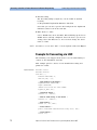
Example for Connecting via GPIB
The following code example shows how to use the VISA library to
connect to the instrument via GPIB.
This example queries a GPIB device for an identification string and
prints the results.
Implementation
#include <visa.h>
#include <stdio.h>
void main () {
ViSession defaultRM, vi;
char buf [256] = {0};
/* Open session to GPIB device at address 22 */
viOpenDefaultRM (&defaultRM);
viOpen (defaultRM, "GPIB0::22::INSTR", VI_NULL,VI_NULL, &vi);
/* Initialize device */
viPrintf (vi, "*RST\n");
/* Send an *IDN? string to the device */
viPrintf (vi, "*IDN?\n");
/* Read results */
viScanf (vi, "%t", &buf);
/* Print results */
printf ("Instrument identification string: %s\n", buf);
/* Close session */
viClose (vi);
viClose (defaultRM);
}
12
Agilent 81133A/81134A Pulse Generator Programming Guide, March 2007
Connecting to the Instrument via LAN
Connecting to the Pulse/Pattern Generator for Remote Programming
Connecting to the Instrument via
LAN
For connecting over the LAN, you would do have the following:
• Connect the instrument to the LAN physically.
• Configure the Agilent IO Libraries on the remote machine.
• On the user interface, either specify the LAN address or—if a
DHCP server is available—enable the DHCP. The DHCP will
automatically set up the LAN connection.
• After the connection has been established, the following
commands can be used to modify the settings:
– Enable/disable DHCP with
:SYST:COMMunicate:LAN[:SELF]:DHCP
– Set the instrument’s LAN name with
:SYST:COMMunicate:LAN[:SELF]:NAME
– Set the instrument's IP address with
:SYST:COMMunicate:LAN[:SELF]:ADDRess
– Set the instrument’s subnet mask with
:SYST:COMMunicate:LAN[:SELF]:SMASk
– Set the instrument’s gateway with
:SYST:COMMunicate:LAN[:SELF]:DGATeway
Configuring the Agilent IO Libraries
Suite 14 of the Agilent IO Libraries does not directly support
interfaces with a SICL name of “lan0”. When you add a LAN
interface, the default SICL name is “inst0”. To ensure compatability
with current code, it is recommended that you change the SICL
name to “lan0”.
To set up and configure the interface:
1 Run Agilent Connection Expert and configure your TCPIP
instrument according to the instructions provided with the
Agilent Connection Expert.
2 Close Agilent Connection Expert.
Agilent 81133A/81134A Pulse Generator Programming Guide, March 2007
13
Connecting to the Pulse/Pattern Generator for Remote Programming
Connecting to the Instrument via LAN
3 Run IO Config.
The IO Config utility (iocfg32.exe) can be found at (default
location):
C:\Program Files\Agilent\IO Libraries Suite\bin
Note that you can also open the IO Config from the Agilent IO
Libraries Control icon in the task bar.
4 Edit “inst0” to “lan0”.
Select “TCPIP Lan”, then click Edit. This will bring up the list of
TCPIP devices already configured. Select the device you need to
change, then click Edit Device. You can now change the device
name to “lan0”.
NOTE
You will see a red circle with “!” in the Agilent Connection Expert.
Example for Connecting via LAN
The following code snippet shows how to use the VISA library to
connect to the instrument via LAN.
This example queries a device for an identification string and
prints the results.
Implementation
#include <visa.h>
#include <stdio.h>
void main () {
ViSession defaultRM, vi;
char buf [256] = {0};
/* Open session to the device */
viOpenDefaultRM (&defaultRM);
viOpen (defaultRM,
"TCPIP0::123.123.123.123::lan0::INSTR"
VI_NULL,VI_NULL, &vi);
/* Initialize device */
viPrintf (vi, "*RST\n");
/* Send an *IDN? string to the device */
viPrintf (vi, "*IDN?\n");
/* Read results */
viScanf (vi, "%t", &buf);
/* Print results */
printf ("Instrument identification string: %s\n", buf);
/* Close session */
viClose (vi);
14
Agilent 81133A/81134A Pulse Generator Programming Guide, March 2007
Connecting to the Instrument via USB
Connecting to the Pulse/Pattern Generator for Remote Programming
viClose (defaultRM);
}
Connecting to the Instrument via
USB
NOTE
The control PC must have USB capability for USB connections
(Windows NT is not supported).
For connecting over the USB, please refer to the Help delivered
with the USB driver.
Agilent 81133A/81134A Pulse Generator Programming Guide, March 2007
15
Connecting to the Pulse/Pattern Generator for Remote Programming
16
Connecting to the Instrument via USB
Agilent 81133A/81134A Pulse Generator Programming Guide, March 2007
SCPI Commands Reference
The following sections describe the SCPI Commands available to
program the 81133A/81134A remotely. The commands are divided
into the following functional blocks:
• “Common Commands” on page 19
• “DIAGnostic Commands” on page 23
• “DIGital Commands” on page 25
• “DISPlay Commands” on page 35
• “MEASure Commands” on page 36
• “OUTPut Commands” on page 39
• “SOURce Commands” on page 45
• “Status Handling Commands” on page 67
• “SYSTem Commands” on page 79
• “TRIGger Commands” on page 86
• “ARM Commands” on page 90
Agilent 81133A/81134A Pulse Generator Programming Guide, March 2007
17
SCPI Commands Reference
Command Structure
Each command description has at least some of the following
items:
• Full command syntax
• Form
– Set
The command can be used to program the instrument.
– Query
The command can be used to interrogate the instrument. A
question mark (?) is added to the command, the parameters
may also change.
• Brief description
• Parameters
• Parameter Suffix
The suffixes that may follow the parameter.
• Functional Coupling
Any other commands that are implicitly executed by the
command.
• Value Coupling
Any other parameter that is also changed by the command.
• Range Coupling
Any other parameter whose valid ranges may be changed by the
command.
• *RST value
The value/state following a *RST command
• Specified Limits
• Short example
18
Agilent 81133A/81134A Pulse Generator Programming Guide, March 2007
Common Commands
SCPI Commands Reference
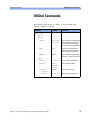
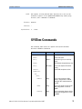
Common Commands
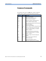
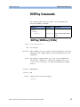
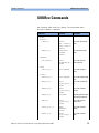
The following table shows the IEEE 488.2 Common Commands
available with the Agilent 81133A/81134A Pulse Generator.
Command
Parameter Description
*CLS
-
Clears the status register
*ESE
<0–255>
Sets the event status register mask
*ESR?
-
Reads the event status register
*IDN?
-
Reads the instrument's identification string
*LRN?
-
Reads a complete instrument setting
*OPC
-
Sets the operation complete bit when all pending
actions are complete
*OPT?
-
Reads the installed options
*RCL
<1–9>
Reads a complete instrument setting from memory
*RCL
<0>
Reads the standard settings from the memory.
For a list of standard settings, see “Standard
Settings” on page 21.
*RST
-
Resets the instrument to standard settings.
For a list of standard settings, see “Standard
Settings” on page 21.
*SAV
<1–9>
Saves the complete instrument setting to the
memory
*SRE
<0–255>
Sets the service request enable mask
*STB?
-
Reads the status byte
*TST?
-
Executes the instrument's self-test
*WAI
-
Waits until all pending actions are complete
Agilent 81133A/81134A Pulse Generator Programming Guide, March 2007
19
SCPI Commands Reference
Commands in the User Interface
Common Commands
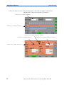
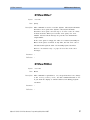
The following figure shows how the IEEE 488.2 Common
commands are implemented in the 81133A/81134A user interface.
*TST
*SAV
*RCL
20
Agilent 81133A/81134A Pulse Generator Programming Guide, March 2007
Common Commands
SCPI Commands Reference
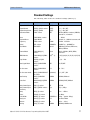
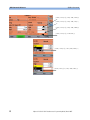
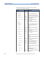
Standard Settings
The following table shows the standard settings (Memory 0).
Parameter
SCPI Command
Reset Value
Range
Outputs On/Off
:OUTP[0|1|2] <value>
0 (OFF)
0 | 1| ON | OFF
Output Normal
:OUTP[1|2]:POS <value> 0 (OFF)
0 | 1 | ON | OFF
Output Complement
:OUTP[1|2]:NEG
0 (OFF)
0 | 1 | ON | OFF
Instrument Mode
:FUNC <value>
PATT
PATTern|BURSt, <number>|RBURSt,
<number1>, <number2>
Burst
:FUNC BURSt, <value>
1
1 … 16384
Repeated Burst
:FUNC RBURS
4, 4
For both, 4 … 16384 in increments of 4
Frequency
:FREQ <value>
15 MHz
15 MHz … 3.35 GHz
Period
:PER <value>
66.666667ns
0.298507 ps … 66.666667 ns
Clock Mode
:TRIG:SOUR
Internal
IMMediate, EXTernal, REFerence,
IDIRect, EDIRect
Channel Mode
:FUNC:MOD[1|2]
<value>
PULSe
PULSe |SQUAre |DATa |PRBS,
<numeric>
PRBS Number
:FUNC:MOD[1|2] PRBS,
<value>
23 (223 - 1)
5|6|7|8|9|10|11|12|13|14|15|23|
31
Freq. Divider
:OUTP[0|1|2]:DIV
<value>
1
1, 2, 4, … 128
Data Signal Mode
:DIG[1|2]:SIGN:FORM
<value>
NRZ
R1, RZ, NRZ
Var. Crossover
:DIG[1|2]:SIGN:CROS
<value>
50 %
30 … 70 %
Var. Crossover mode
:DIG[1|2]:SIGN:CROS:ST 0 (disabled)
AT <value>
0| 1 | OFF | ON
Data Polarity
:DIG[1|2]:SIGN:POL
<value>
NORMal
NORMal, INVerted
Pulse Perf.
DIAG:CHAN[1|2]:PPER
<value>
NORMal
NORMal|FAST|SMOoth
Delay Control Input
:PM[1|2] <value>
OFF
OFF, ON
Delay Control Input
Sensitivity
:PM[1|2]:SENS <value>
25 ps
25 ps | 250 ps
Delay
:DEL[1|2] <value>
0 ns
-5 ns … +230 ns
Phase
:PHAS[1|2] <value>
0
see Delay
Pulse Width
:WIDT[1|2] <value>
33.333333 ns
100 ps … (period -100 ps)
Duty Cycle
:DCYC[1|2] <value>
50 %
See Pulse Width
Deskew
:DESK[1|2] <value>
0ps
-10 ns … +10 ns
Polarity
:POL[1|2] <value>
NORMal
NORMal|COMPlement
Agilent 81133A/81134A Pulse Generator Programming Guide, March 2007
21
SCPI Commands Reference
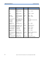
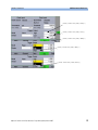
22
Common Commands
Parameter
SCPI Command
Reset Value
Range
Low Level
:VOLT[0|1|2]:LOW
<value>
-50 mV
-2.00 V … +2.95 V
High
:VOLT[0|1|2]:HIGH
<value>
50 mV
-1.95 V … +3.00 V
Offset
:VOLT[0|1|2]:OFFS
<value>
0 mV
-1.975 V … +2.975 V
Amplitude
:VOLT[0|1|2] <value>
100 mV
50 mV … 2.00 V
Term. Voltage
:VOLT[0|1|2]:TERM
<value>
0 mV
-2.00 V … +3.00 V
Limit to current levels
:VOLT[1|2]:LIM <value>
OFF
OFF, ON
Data Length
:DIG:PATT:LENG <value> 32
32 … 8192 (in increments of 32)
Clock Input
Termination
:TRIG:TERM:STATE
<value>
OFF
ON, OFF
Clock Input Term.
Voltage
:TRIG:TERM <value>
0 mV
-2.00 … +3.00 V
Trigger Output Mode
:OUTP0:SOUR <value>
PERiodic
PERiodic, BITStream
Trigger Output Divider :OUTP0:DIV <value>
1
1, 2, 3, … (231 - 1)
Trigger Output High
see High Level
50 mV
-1.95 V … +3.00 V
Trigger Output Low
see Low Level
-50 mV
-2.00 … +2.95 V
Trigger Output Term.
Voltage
see Term. Voltage
0 mV
-2.00 … +3.00 V
Start Input Start Mode :ARM:SOUR <value>
IMMediate
IMMediate|MANual|EXTernal
Start Input Term.
Voltage
:ARM:TERM <value>
0 mV
-2.00 … +3.00 V
Start Input Threshold
:ARM:LEV <value>
100 mV
-2.00 … +3.00 V
Start Input Start On
:ARM:SLOP <value>
POS (rising)
POS, NEG (rising/falling)
Agilent 81133A/81134A Pulse Generator Programming Guide, March 2007
DIAGnostic Commands
SCPI Commands Reference
DIAGnostic Commands
The following table shows the Agilent 81133A/81134A Pulse
Generator DIAGnostic Commands.
Command
:CAL:TIM
Parameter
Description
Calibrates the timing system of
the instrument
:DIAG
:CHANnel[1|2]
:PPERformance[?]
Commands in the User Interface
NORMal | FAST Sets/reads channel peak
| SMOoth
performance
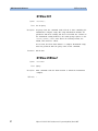
The following figure shows how the DIAGnostic commands are
implemented in the 81133A/81134A user interface.
:TEST?
:CAL:TIM
:DIAG:CHANnel[1|2]
:PPERformance[?]
Agilent 81133A/81134A Pulse Generator Programming Guide, March 2007
23
SCPI Commands Reference
DIAGnostic Commands
:CAL:TIM
Syntax
Form
Description
NOTE
*RST value
:CAL:TIM
Set
Calibrates the timing system of the instrument.
Execution of this command can take about 15 minutes.
–
:DIAG:CHANnel[1|2]:PPERformance
Syntax
Form
Description
:DIAG:CHAN[1|2]:PPER[?]
Set & Query
This command is used to modify the specified transition time of
the signal.
For the specified transition time, please refer to the Technical
Specification delivered on the product CD.
Parameter
NORMal|FAST|SMOoth
• Normal
Produces pulses with the standard transition time specified for
the instrument.
For the specified transition time, please refer to the Technical
Specification delivered on the product CD.
• Fast
Reduces the transition time. This leads to a higher slew rate but
more overshoot.
• Smooth
Produces a rounder output pulse, with lower slew rate and less
overshoot.
*RST value
Example
Normal
Set the Peak Performance to Fast.
:DIAG:CHANnel:PPER FAST
24
Agilent 81133A/81134A Pulse Generator Programming Guide, March 2007
DIGital Commands
SCPI Commands Reference
DIGital Commands
The following table shows the Agilent 81133A/81134A Pulse
Generator DIGital commands:
Command
Parameter
Description
:DIGital[1|2]
[:STIMulus]
:PATTern
[:DATa][?]
<data>, [HEX | Sets/reads data in hexadecimal
BIN | DUAL]
(default), binary or dual format;
this command is for data patterns with maximum 8192 bits
:LDATa
<data>
Sets data in hexadecimal format; this command is for data
patterns larger than 8192 bits
:LENGth[?]
Numeric
Sets/reads data pattern length
in bits (32 ... 8192) in steps of 32
:SIGNal
:FORMat[?]
RZ | NRZ | R1 Sets/reads the signal mode
:POLarity[?]
NORMal |
COMPlement |
INVerted
Sets/reads data polarity
:CROSsover
:[VALUE][?]
Numeric
Sets/reads crossover
:STATe[?]
Agilent 81133A/81134A Pulse Generator Programming Guide, March 2007
ON | OFF | 1 | Switches crossover on/off
0
25
SCPI Commands Reference
Commands in the User Interface
DIGital Commands
The following figures show how the DIGital commands are
implemented in the 81133A/81134A user interface.
:DIGital[1|2]:PATTern:LENGth[?]
:DIGital[1|2]:PATTern:[DATa][?]
:DIGital[1|2]:SIGNal:CROSsover:STATE[?]
:DIGital[1|2]:SIGNal:FORMat[?]
:DIGital[1|2]:SIGNal:CROSsover:[VALue][?]
:DIGital[1|2]:SIGNal:POLarity[?]
26
Agilent 81133A/81134A Pulse Generator Programming Guide, March 2007
DIGital Commands
SCPI Commands Reference
:DIGital[1|2][:STIMulus]:PATTern[:DATa]
Syntax
Form
Description
:DIG[1|2][:STIM]:PATT[:DAT][?]
Set & Query
This command is used to set or read the pattern data of one of
the channels. The minimum length of these patterns is 32 bits, the
maximum length is 8192 bits, the granularity is 32 bits. For
patterns larger than 8192 bits, see
“:DIGital[1|2][:STIMulus]:PATTern:LDATa” on page 29.
The data can be written in either hexadecimal, binary or dual
format. The query returns the data in hexadecimal format.
For the command, the format is specified by the format parameter;
HEX is the default.
• Hexadecimal
With the hexadecimal format, the characters passed as the data
pattern will be interpreted as hexadecimal values.
The MSB of the first character becomes bit 0 of the data
pattern.
• Binary
With the binary format, the ASCII values of the characters
passed are used to build the data pattern.
• Dual
With the dual format, you can use “0” and “1” to build the data
pattern.
Parameter
<data>, [HEX | BIN | DUAL]
Agilent 81133A/81134A Pulse Generator Programming Guide, March 2007
27
SCPI Commands Reference
DIGital Commands
The <data> is an arbitrary block of program data as defined in
IEEE 488.2 7.7.6.2, for example:
#181CF1011E, HEX
#
Start of block
1
Length of the length of the data
8
Length of the data (in bytes)
1CF1011E
32 bits of pattern data
HEX
Data in hex format
#23201001001001001010100101010100110, DUAL
#
Start of block
2
Length of the length of the data
32
Length of the data (in bytes)
010...110 32 bits of pattern data
DUAL
Data in dual format
#14@@@@, BIN
*RST value
Example
#
Start of block
1
Length of the length of the data
4
Length of the data (in bytes)
@@@@
32 bits of pattern data
BIN
Data in binary format
4 bytes with the binary value 00010001
The examples above would be sent as follows:
:DIG:PATT #181CF1011E[, HEX]
:DIG:PATT?
>#181CF1011E
:DIG:PATT #23201001001001001010100101010100110, DUAL
:DIG:PATT?
>#1849254AA6
:DIG:PATT #14@@@@, BIN
:DIG:PATT?
>#1840404040
28
Agilent 81133A/81134A Pulse Generator Programming Guide, March 2007
DIGital Commands
SCPI Commands Reference
:DIGital[1|2][:STIMulus]:PATTern:LDATa
Syntax
Form
Description
Parameter
:DIG[1|2][:STIM]:PATT:LDAT
Set
This command is used to program long data patterns in
hexadecimal format. The minimum length of these patterns is 128
bits, the maximum length is 12 Mbits, the granularity is 128 bits.
Patterns generated with this command are subject to various
restrictions (see below). See also
“:DIGital[1|2][:STIMulus]:PATTern[:DATa]” on page 27.
<data>
The <data> is an arbitrary block of hex program data as defined in
IEEE 488.2 7.7.6.2, for example:
#532768AB03CDAD......
#
Start of block
5
Length of the length of the data
32768
Length of the data
AB03CD... 32768 bytes of data for pattern
length of 131072 bits
Restrictions
This command is subject to the following restrictions:
• Only pattern up to 12 Mbits and a granularity of 128 bits are
allowed.
• Because of hardware restrictions, a complete 12 Mbit pattern
can only be sent at higher frequency ranges:
Range
Maximum Pattern Length
60 – 3360 Mhz
12 Mbit
30 – 60 Mhz
6 Mbit
15 – 30 Mhz
3 Mbit
• The frequency divider of a two- channel instrument also restricts
the maximum pattern. The following equation is valid:
Max. pattern size =
Max. pattern size (@ freq)
Frequency divider
Agilent 81133A/81134A Pulse Generator Programming Guide, March 2007
29
SCPI Commands Reference
DIGital Commands
• The complete pattern is stored temporarily in the instrument. If
there are no restrictions to the maximum pattern length
regarding frequency and frequency divider, the complete pattern
will always be continually emitted. If there are restrictions to
the maximum pattern length, the stored pattern will be emitted
up to the maximum pattern length and then repeated from the
beginning.
• The channel mode must be data mode.
• The main mode of the instrument must be Pulse/Pattern. Burst
and RBurst mode are not allowed.
• The extended pattern is lost by any of the following actions:
– Modifying the pattern in the pattern editor of the user
interface
– Sending another pattern by :DIG:PATT:DATA or
:DIG:PATT:LDAT
– Changing channel mode or main mode of the instrument
– Recalling a setting or resetting the instrument
– Restarting the instrument
In all these cases, the pattern length is set to the actual data
length.
*RST value
Example
–
The above example would be sent as:
:DIG:PATT:LDAT #532768AB03CDAD......
30
Agilent 81133A/81134A Pulse Generator Programming Guide, March 2007
DIGital Commands
SCPI Commands Reference
:DIGital[1|2][:STIMulus]:PATTern:LENGth
Syntax
Form
Description
Parameter
:DIG[1|2][:STIM]:PATT:LENG[?]
Set & Query
Defines the length of the data pattern. If the current pattern is
longer than the new value for :LENGth, the pattern is truncated. If
the current pattern is shorter than the new value for :LENGth, the
pattern is lengthened and the new bits are set to ’0’.
Numeric
Valid values are:
32 … 8192 in steps of 32.
*RST value
Example
32
Define a data pattern length of 64 bits.
:DIG:PATT:LENG 64
:DIGital[1|2][:STIMulus]:SIGNal:FORMat
Syntax
Form
Description
Parameter
:DIG[1|2][:STIM]:SIGN:FORM[?]
Set & Query
This command is used to program the signal format for data and
PRBS signals:
RZ|NRZ|R1
• RZ
Return to Zero. A pulse of 50% duty cycle is generated for each
1.
• NRZ
Non- Return to Zero. A pulse of 100% duty cycle is generated for
each 1.
• R1
Return to One. A pulse of 100% duty cycle is generated for each
0.
*RST value
NRZ
Agilent 81133A/81134A Pulse Generator Programming Guide, March 2007
31
SCPI Commands Reference
DIGital Commands
Example
Set data format to R1.
:DIG:SIGN:FORM R1
:DIGital[1|2][:STIMulus]:SIGNal:POLarity
Syntax
Form
Description
NOTE
Parameter
:DIG[1|2][:STIM]:SIGN:POL[?]
Set & Query
This command is used to program the data polarity for Data and
PRBS signals. The 32- bit data pattern is logically inverted, that is,
1 s are replaced with 0 s and vice versa.
This is not the same as the [:SOURce][:PULSe]:POLarity[1|2]
command, which physically inverts the signal by swapping the
OUTPUT and OUTPUT signals.
NORMal|COMPlement|INVerted
INVerted are synonyms (INVerted is included for backwards
compatibility).
*RST value
Example
NORMal
Logically invert the 32- bit data.
:DIG:SIGN:POL INV
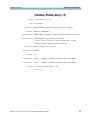
:DIGital[1|2][:STIMulus]:SIGNal:
CROSsover:[VALue]
Syntax
Form
Description
:DIG[1|2][:STIM]:SIGN:CROS[?]
Set & Query
If variable crossover mode is enabled, this command specifies a
value to adjust the crossover point of the NRZ signal in PRBS or
data mode, individually for each channel.
To enable the variable crossover mode, use
“:DIGital[1|2][:STIMulus]:SIGNal: CROSsover:[STATe]” on page 34.
The variable crossover is used to artificially close the eye pattern,
which simulates distortion.
32
Agilent 81133A/81134A Pulse Generator Programming Guide, March 2007
DIGital Commands
SCPI Commands Reference
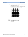
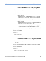
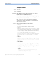
NOTE
This parameter has no influence if the delay control input for the
channel is switched on (:PM[1|2] ON).
The figure below shows the normal and complement output with
the crossover point set to 50% and 70% respectively.
50 %
Normal
Out
50 %
Compl.
Out
70 %
Normal
Out
70 %
Compl.
Out
Parameter
Numeric values (in %) in the range of 20 … 80.
*RST value
50
Example
Set the variable crossover point to 70%.
:DIG:SIGN:CROS 70
Agilent 81133A/81134A Pulse Generator Programming Guide, March 2007
33
SCPI Commands Reference
DIGital Commands
:DIGital[1|2][:STIMulus]:SIGNal:
CROSsover:[STATe]
Syntax
Form
Description
:DIG[1|2][:STIM]:SIGN:CROS:STAT[?]
Set & Query
For each channel, the crossover mode of the NRZ signal in PRBS
or data pattern mode can be enabled. This is used to artificially
close the eye pattern, simulating distortion.
If you enabled the variable crossover mode, specify the variable
crossover point with “:DIGital[1|2][:STIMulus]:SIGNal:
CROSsover:[VALue]” on page 32.
Parameter
ON|OFF|1|0
*RST value
OFF|0
Example
Enable the variable crossover mode.
:DIG:SIGN:CROS:STAT ON
34
Agilent 81133A/81134A Pulse Generator Programming Guide, March 2007
DISPlay Commands
SCPI Commands Reference
DISPlay Commands
The following table shows the Agilent 81133A/81134A Pulse
Generator DISPlay commands.
Command
Parameter
Description
:DISPlay
[:WINDow]
[:STATe][?]
ON | OFF | 1 | Sets/reads front panel display
0
state
:DISPlay[:WINDow][:STATe]
Syntax
Form
Description
NOTE
:DISP[:WIND][:STAT][?]
Set & Query
This command is used to turn the front panel display on and off.
Switching off the display improves the programming speed of the
instrument.
The display is switched back on if a key on the instrument is
pressed. The command *RST switches the display back on. Use
:SYSTem:PRESet to perform a *RST without switching the display
back on.
Parameter
ON|OFF|1|0
*RST value
ON
Example
Switch off the front panel display.
:DISP OFF
Agilent 81133A/81134A Pulse Generator Programming Guide, March 2007
35
SCPI Commands Reference
MEASure Commands
MEASure Commands
The following table shows the Agilent 81133A/81134A Pulse
Generator MEASure commands:
Command
Parameter Description
:MEASure
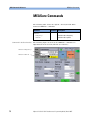
Commands in the User Interface
:FREQuency?
Read time base frequency
:PERiod?
Read time base period
The following figure shows how the MEASure commands are
implemented in the 81133A/81134A user interface.
:MEASure:FREQuency?
:MEASure:PERiod?
36
Agilent 81133A/81134A Pulse Generator Programming Guide, March 2007
MEASure Commands
SCPI Commands Reference
:MEASure:FREQuency?
Syntax
Form
Description
:MEAS:FREQ?
Query
This command is used to measure the operating frequency of the
instrument.
In internal mode (:TRIGger:SOURce IMMediate) the frequency
returned is the measured internal clock frequency (not the
programmed value).
In external mode (:TRIGger:SOURce EXTernal) the frequency returned
is that measured at the Clock Input connector. If an invalid signal,
or no signal, is present at the Clock Input connector, a value of
zero is returned.
The query does not return a value immediately, but waits for the
internal frequency counter to complete its next measurement cycle.
This can take about half a second.
NOTE
The instrument is stopped when this command is executed. Thus,
during the measurement, no signals will be output.
NOTE
When working in an automated test system, if the clock frequency
is known, it is better to set it directly instead of reading it from
the instrument. This is because:
• This method is faster since it eliminates the measurement time.
• The instrument is not stopped.
Parameter
–
*RST value
–
Example
:MEAS:FREQ?
Agilent 81133A/81134A Pulse Generator Programming Guide, March 2007
37
SCPI Commands Reference
MEASure Commands
:MEASure:PERiod?
Syntax
Form
Description
:MEAS:PER?
Query
This command is used to read the operating period of the
instrument.
In internal mode (:TRIGger:SOURce IMMediate) the period returned is
the internal clock period.
In external mode (:TRIGger:SOURce EXTernal) the period returned is
that measured at the Clock Input connector. If an invalid signal, or
no signal, is present at the Clock Input connector, a value of zero
is returned.
The query does not return a value immediately, as it waits for the
internal frequency counter to complete its next measurement cycle.
This can take about half a second.
NOTE
The instrument is stopped when this command is executed. Thus,
during the measurement, no signals will be output.
NOTE
When working in an automated test system, if the clock frequency
is known, it is better to set it directly instead of reading it from
the instrument. This is because:
• This method is faster since it eliminates the measurement time.
• The instrument is not stopped.
Parameter
–
*RST value
–
Example
38
:MEAS:PER?
Agilent 81133A/81134A Pulse Generator Programming Guide, March 2007
OUTPut Commands
SCPI Commands Reference
OUTPut Commands
The following table shows the Agilent 81133A/81134A Pulse
Generator OUTPut commands.
Command
Parameter
Description
[0|1|2]:DIVider[?]
Numeric | MIN |
MAX
Set/read channel frequency
divider
[0]:SOURce[?]
PERiodic |
BITStream
Set/read trigger source mode
[0|1|2][:STATe][?]
ON | OFF | 1 | 0 Set/read channel outputs on
and off
[1|2]:NEG[?]
ON | OFF | 1 | 0 Set/read negative channel
output on and off
[1|2]:POS[?]
ON | OFF | 1 | 0 Set/read positive channel output on and off
:CENTral[?]
ON | OFF | 1 | 0 Set/read central output settings
:OUTPut
Agilent 81133A/81134A Pulse Generator Programming Guide, March 2007
39
SCPI Commands Reference
Commands in the User Interface
OUTPut Commands
The following figures show how the DIAGnostic commands are
implemented in the 81133A/81134A user interface.
:OUTPut[0|1|2][:STATe][?]
:OUTPut:CENTral[?]
:OUTPut[1]:DIVider[?]
OUTPut[1]:POS[?]
OUTPut[1]:NEG[?]
:OUTPut[0]:DIVider[?]
40
Agilent 81133A/81134A Pulse Generator Programming Guide, March 2007
OUTPut Commands
SCPI Commands Reference
:OUTPut[0|1|2]:DIVider
Syntax
Form
Description
:OUTP[0|1|2]:DIV[?]
Set & Query
This command is used to program the frequency divider
parameters of the trigger output (0) and the channel outputs (1,
2).
The trigger output frequency is divided only when the trigger
output is in Pulse mode (:OUTPut0:SOURce PERiodic).
You can program the divider in Data mode (:OUTPut0:SOURce
BITstream) but it will have no effect until you select the trigger
output to pulse mode.
The channel output frequency is divided in square and pulse
pattern mode only ([SOURce]:FUNCtion:MODe[1|2] SQUare|PULSe).
You can program the divider in data and PRBS pattern mode
([SOURce]:FUNCtion:MODe[1|2] DATa|PRBS), but it will have no effect
until you select the square or pulse pattern mode.
Parameter
Numeric|MIN|MAX
*RST value
1
Specified Limits
For trigger output (channel 0): 1 ... 231 – 1
For channels 1 and 2: 1, 2, 4, 8, 16, 32, 64, 128
Example
Set Trigger Output Divider to 8.
:OUTP0:DIV 8
Agilent 81133A/81134A Pulse Generator Programming Guide, March 2007
41
SCPI Commands Reference
OUTPut Commands
:OUTPut0:SOURce
Syntax
Form
Description
:OUTP0:SOUR[?]
Set & Query
This command programs the trigger output source mode.
• PERiodic
This corresponds to Pulse mode on the front panel.
The trigger source is the internal clock, and a trigger pulse is
generated every clock period, unless the divider parameter has
been set to a value other than 1. The trigger signal always has
50% nominal duty cycle.
• BITStream
This corresponds to the Data mode on the front panel.
If the clock source is external, the trigger is always synchronized
to the clock with a fixed delay (± a few picoseconds over the
frequency range). PERiodic means that a trigger pulse is
generated for every X clocks, BITStream means that X is set to
the data length.
The trigger divider does not take the frequency divider of the
channels into account. For a frequency divider of n, n trigger
pulses are generated for each data packet, starting with the first
edge of bit 0 of the data packet.
To get one trigger pulse per data packet when the channel
divider factor is not equal to 1, the trigger mode must set to
Trigger on pulse and the divider to n x X, where n is the
frequency divider and X is the data length. For example, if the
data length = 32 bits and the frequency divider of channel 1 = 2,
the frequency divider of the trigger output has to be 64.
Parameter
PERiodic|BITStream
*RST value
PERiodic
Example
Synchronize the trigger output signal to the data.
:OUTP0:SOUR BITS
42
Agilent 81133A/81134A Pulse Generator Programming Guide, March 2007
OUTPut Commands
SCPI Commands Reference
:OUTPut[0|1|2][:STATe]
Syntax
Form
Description
:OUTP[0|1|2][:STAT][?]
Set & Query
Switches the trigger output and channel outputs on or off, where 0
is the trigger output.
For the two channel outputs, both OUTPUT and OUTPUT are
switched simultaneously. In query form, OFF is returned only if
both OUTPUT and OUTPUT are off. They can be controlled
separately from the front panel, or by adding :POS or :NEG to the
command.
Parameter
ON|OFF|1|0
*RST value
OFF
Example
Switch on the channel 1 outputs.
:OUTP1 ON
:OUTPut[1|2]:NEG
Syntax
Form
Description
:OUTP[1|2]:NEG[?]
Set & Query
Switches the specified channel OUTPUT on or off.
Parameter
ON|OFF|1|0
*RST value
OFF
Example
Switch off the channel 1 OUTPUT.
:OUTP1:NEG OFF
Agilent 81133A/81134A Pulse Generator Programming Guide, March 2007
43
SCPI Commands Reference
OUTPut Commands
:OUTPut[1|2]:POS
Syntax
Form
Description
:OUTP[1|2]:POS[?]
Set & Query
Switches the specified channel OUTPUT on or off.
Parameter
ON|OFF|1|0
*RST value
OFF
Example
Switch off the channel 1 OUTPUT.
:OUTP1:POS OFF
:OUTPut:CENTral
Syntax
Form
Description
:OUTP:CENT[?]
Set & Query
Sets or reads the central output settings.
The OFF command forces all outputs (trigger output and channel
outputs) to be switched off, the ON command switches on every
output that is set to on by the other :OUTPut commands.
Parameter
ON|OFF|1|0
*RST value
1
Example
Switches off all output channels.
:OUTP:CENT OFF
44
Agilent 81133A/81134A Pulse Generator Programming Guide, March 2007
SOURce Commands
SCPI Commands Reference
SOURce Commands
The following table shows the Agilent 81133A/81134A Pulse
Generator SOURce commands:
Command
Parameter
Description
[:SOURce]
:FUNCtion
[:SHAPe][?]
PATTern|
Sets/reads instrument
BURSt, <numeric>| mode
RBURSt, <numeric>,
<numeric>
:MODE[1|2][?]
PULSe|SQUare|
DATa|PRBS
<numeric>
Sets instrument main
mode
:FREQuency
[:CW|:FIXed][?]
Numeric
Sets/reads internal
[GHz|MHz|kHz|Hz] | clock frequency
MIN|MAX
:PHASe
[:ADJ][1|2][?]
Numeric|MIN|MAX
Sets/reads channel
phase
:DCYCle[1|2][?]
Numeric|MIN|MAX
Sets/reads channel duty
cycle
:DELay[1|2][?]
Numeric
[ps|ns|us|ms|s] |
MIN|MAX
Sets/reads channel delay
:DESKew[1|2][?]
Numeric
[ps|ns|us|ms|s]|
MIN|MAX
Sets/reads channel
deskew
:DHOLd[1|2][?]
DELay|PHASe
Holds Delay|Phase fixed
with varying frequency
:PERiod[?]
Numeric
[ps|ns|us|ms|s] |
MIN|MAX
Sets/reads internal
clock period
:POLarity[1|2][?]
NORMal|
COMPlement|
INVerted
Sets/reads channel
polarity
:WIDTh[1|2][?]
Numeric
[ps|ns|us|ms|s] |
MIN|MAX
Sets/reads channel
width
[:PULSe]
Agilent 81133A/81134A Pulse Generator Programming Guide, March 2007
45
SCPI Commands Reference
SOURce Commands
Command
Parameter
Description
OFF|ON
Sets/reads jitter
modulation
25ps|250ps
Sets jitter modulation
sensitivity
[:AMPLitude][?]
Numeric [uV|mV|V]
|MIN|MAX
Sets/reads channel
amplitude
:OFFSet[?]
Numeric [uV|mV|V]
|MIN|MAX
Sets/reads channel
offset
:HIGH[?]
Numeric [uV|mV|V]
|MIN|MAX
Sets/reads channel
high-level
:LOW[?]
Numeric [uV|mV|V]
|MIN|MAX
Sets/reads channel lowlevel
:TERM[?]
Numeric [uV|mV|V]
Sets/reads termination
voltage
PM[1|2][?]
:SENSitivity
:VOLTage
[0|1|2][:LEVel]
[:IMMediate]
[1|2]:LIMit
[:AMPLitude]?
Reads channel
amplitude limit
:OFFSet?
Reads channel offset
limit
:HIGH?
Reads channel high-level
limit
:LOW?
Reads channel low-level
limit
:STATe[?]
46
ON|OFF|1|0
Sets/reads limited
output mode on and off
Agilent 81133A/81134A Pulse Generator Programming Guide, March 2007
SOURce Commands
Commands in the User Interface
SCPI Commands Reference
The following figures show how the DIAGnostic commands are
implemented in the 81133A/81134A user interface.
[:SOURce]:FUNCtion[:SHAPe]
[:SOUR]:FREQ[:CW|:FIX][?]
[:SOUR][:PULS]:PER[?]
[:SOUR]:FUNC:MOD[1|2][?]
[:SOUR]:PM[1|2][?]
[:SOUR][:PULS]:DEL[1|2][?]
[:SOUR][:PULS]:WIDT[1|2][?]
[:SOUR][:PULS]:DESK[1|2][?]
[:SOUR]:VOLT[0|1|2][:LEV][:IMM]:TERM[?]
[:SOUR]:PM[1|2]:SENS
[:SOUR]:PHAS[:ADJ][1|2][?]
[:SOUR][:PULS]:DCYC[1|2][?]
Agilent 81133A/81134A Pulse Generator Programming Guide, March 2007
47
SCPI Commands Reference
SOURce Commands
[:SOUR]:VOLT[1|2]:LEV[:IMM]:HIGH[?]
[:SOUR]:VOLT[1|2]:LEV[:IMM]:LOW[?]
[:SOUR]:VOLT[1|2]:LEV[:IMM]:TERM[?]
[:SOUR]:VOLT[1|2]:LIM:STAT[?]
[:SOUR]:VOLT[1|2]:LEV[:IMM]:AMPL[?]
[:SOUR]:VOLT[1|2]:LEV[:IMM]:OFFS[?]
48
Agilent 81133A/81134A Pulse Generator Programming Guide, March 2007
SOURce Commands
SCPI Commands Reference
[:SOUR]:VOLT0:LEV[:IMM]:HIGH[?]
[:SOUR]:VOLT0:LEV[:IMM]:LOW[?]
[:SOUR]:VOLT0:LEV[:IMM]:TERM[?]
[:SOUR]:VOLT0:LEV[:IMM]:AMPL[?]
[:SOUR]:VOLT0:LEV[:IMM]:OFFS[?]
Agilent 81133A/81134A Pulse Generator Programming Guide, March 2007
49
SCPI Commands Reference
SOURce Commands
[:SOURce]:FUNCtion[:SHAPe]
Syntax
Form
Description
Parameter
[:SOUR]:FUNC[:SHAP][?]
Set & Query
Defines the main mode of the signal to be generated
(pulse/pattern, burst, or repetitive burst mode).
PATTern|BURSt, <numeric>|RBURSt, <numeric>, <numeric>
• PATTern
In this mode, each channel can be set independently to generate:
– Square waves of fixed width
– Pulses with selectable width or duty cycle
– Data in either RZ, R1 or NRZ format
– Pseudo random bit stream (PRBS) polynomials
To generate these signals, use “[:SOURce]:FUNCtion:MODe[1|2]”
on page 51.
• BURSt, <number of repeated data>
This mode enables you to generate a burst consisting of data
repeated n times followed by continuous zero data.
*RST value: 1
• RBURSt, <number of repeated data>, <p>
This mode enables you to generate a repeated burst consisting of
data repeated n times. A pause of zeros is inserted between two
successive bursts. The pause of zeros is calculated by:
Length of the pause = Burst Length × p
*RST values: 4, 4
*RST value
Example
PATT
Generate a burst of data repeated 5 times:
:FUNC BURSt, 5
50
Agilent 81133A/81134A Pulse Generator Programming Guide, March 2007
SOURce Commands
SCPI Commands Reference
[:SOURce]:FUNCtion:MODe[1|2]
Syntax
Form
Description
Parameter
[:SOUR]:FUNC:MOD[1|2][?]
Set & Query
Use this command to set the pattern mode for each channel. The
pattern modes specify pulses, clocks, data patterns or PRBS
signals.
PULSe | SQUare | DATa | PRBS, <numeric>
• SQUare
Generates a square wave (clock) of fixed width (50% duty cycle).
The frequency of the square wave can optionally be divided by
1, 2, 4, …, 128 with :OUTPut[1|2]:DIVider.
• PULSe
Generates pulses with selectable width or duty cycle. The
frequency of the pulses can optionally be divided by 1, 2, 4,
…, 128 with :OUTPut[1|2]:DIVider.
• DATa
Generates data in either RZ, R1 or NRZ format as specified with
:DIG[1|2][:STIM]:SIGN:FORM[?].
In RZ and R1 mode, the pulse width can be set. Set the pulse
width with [:SOUR][:PULS]:WIDT[1|2][?].
The frequency of the data can optionally be divided by 1, 2, 4,
…, 128 with :OUTPut[1|2]:DIVider.
• PRBS, <numeric>
Generates a PRBS polynomial of selectable type in either RZ, R1
or NRZ format. In RZ and R1 mode, the pulse width can be set.
Set the pulse width with [:SOUR][:PULS]:WIDT[1|2][?].
The frequency of the PRBS signals can optionally be divided by
1, 2, 4, …, 128 with :OUTPut[1|2]:DIVider.
Valid values are: 25–1 ... 231–1
*RST value
Example
PULSe
Generate a PRBS signal of 25–1 on channel 1:
1. Set the Pulse/Pattern mode:
[:SOUR]:FUNC[:SHAP] PATT
2. Set the PRBS signal:
[:SOUR]:FUNC:MOD[1|2] PRBS, 31
Agilent 81133A/81134A Pulse Generator Programming Guide, March 2007
51
SCPI Commands Reference
SOURce Commands
[:SOURce]:FREQuency[:CW|:FIXed]
Syntax
Form
Description
Parameter
Value coupling
*RST value
Specified limits
Example
[:SOUR]:FREQ[:CW|:FIX][?]
Set & Query
This command programs the internal clock frequency, and also
selects the internal clock as time base if it is not already selected.
Numeric [GHz|MHz|kHz|Hz] | MIN|MAX
Period = 1 / Frequency
15.0E6 Hz
15E6 ... 3.35E9 Hz, with overclocking up to 3.35E9 Hz
Select the clock with frequency 1.2 GHz.
:FREQ 1.2GHz
52
Agilent 81133A/81134A Pulse Generator Programming Guide, March 2007
SOURce Commands
SCPI Commands Reference
[:SOURce]:PHASe[:ADJ][1|2]
Syntax
Form
Description
Parameter
Parameter Suffix
Functional coupling
Value coupling
Range coupling
*RST value
[:SOUR]:PHAS[:ADJ][1|2][?]
Set & Query
This command programs the pulse phase for a channel.
Numeric | MIN|MAX
DEG or RAD. A parameter without suffix is interpreted as degrees.
Programming the pulse phase also executes
[:SOURce][:PULSe]:HOLD PHASe so that the pulse phase is held
constant when the signal frequency is changed.
Delay = (Phase / 360) * Period
Deskew
0.0
Specified limits
–6000° … +279000°, constrained by delay and period limits.
Absolute limits
–6000° … +279000°, constrained by delay and period limits.
Example
Set channel 1 phase delay to –180°.
:PHAS1 -180
Agilent 81133A/81134A Pulse Generator Programming Guide, March 2007
53
SCPI Commands Reference
SOURce Commands
[:SOURce][:PULSe]:DCYCle[1|2]
Syntax
Form
Description
NOTE
[:SOUR][:PULS]:DCYC[1|2][?]
Set & Query
This command programs the duty cycle for a channel.
The duty cycle cannot be set:
• In direct mode. To query the clock source, see
“:TRIGger:SOURce” on page 87.
• If signal mode is set to NRZ. To query the signal mode, see
“:DIGital[1|2][:STIMulus]:SIGNal:FORMat” on page 31.
Parameter
Functional coupling
Value coupling
Range coupling
*RST value
NOTE
Example
Numeric|MIN|MAX
Programming the pulse duty cycle also executes
[:SOURce][:PULSe]:HOLD DCYCLE so that the pulse duty cycle is held
constant when the signal frequency is changed.
Width = (duty cycle / 100) * Period
Frequency, Period
50% (derived from WIDth and PERiod)
The DCYCle command holds the PERiod and WIDth values in
proportion (if one value is increased 50 %, the other value is also
increased 50 %). Its limits are therefore dependent on the limits of
PERiod and WIDth.
Set channel 1 duty cycle to 66%.
:DCYC1 66
54
Agilent 81133A/81134A Pulse Generator Programming Guide, March 2007
SOURce Commands
SCPI Commands Reference
[:SOURce][:PULSe]:DELay[1|2]
Syntax
Form
Description
Parameter
Functional coupling
Value coupling
Range coupling
*RST value
[:SOUR][:PULS]:DEL[1|2][?]
Set & Query
This command programs the pulse delay for a channel.
Numeric [ps|ns|us|ms|s]|MIN|MAX
Programming the pulse delay also executes the
[:SOURce][:PULSe]:DHOLD DELays so that the pulse delay is held
constant when the signal frequency is changed.
Phase = (Delay / Period) * 360
Deskew
0.0
Specified limits
–5 ns … + 230 ns
Absolute limits
–5 ns <= <value in absolute delay time> + <Deskew> <= 230 ns
Example
Set Channel 1 Delay to 500 ps.
:DEL1 500PS
Agilent 81133A/81134A Pulse Generator Programming Guide, March 2007
55
SCPI Commands Reference
SOURce Commands
[:SOURce][:PULSe]:DESKew[1|2]
Syntax
Form
Description
[:SOUR][:PULS]:DESK[1|2][?]
Set & Query
This command programs the deskew for a channel. The deskew
allows you to move the zero- point of the delay (and phase)
parameter by ± 10 ns.
The final delay at the output is Delay + Deskew.
Parameter
Range coupling
*RST value
Numeric [ps|ns|us|ms|s]|MIN|MAX
Delay, Phase
0.0
Specified limits
–10E–9 … 10E–9, but deskew and delay must be within the delay
limits.
Absolute limits
–10E–9 … 10E–9
Example
Set Channel 1 deskew to –155 ps.
:DESK1 -155PS
[:SOURce][:PULSe]:DHOLd[1|2]
Syntax
Form
Description
[:SOUR][:PULS]:DHOL[1|2][?]
Set & Query
Defines whether the pulse delay or the pulse phase of a channel is
held constant when the signal frequency is changed.
Parameter
DELay|PHASe
*RST value
DELay
Example
Hold Channel 1 Delay fixed when frequency varies.
:DHOL1 DEL
56
Agilent 81133A/81134A Pulse Generator Programming Guide, March 2007
SOURce Commands
SCPI Commands Reference
[:SOURce][:PULSe]:PERiod
Syntax
Form
Description
Parameter
Functional coupling
Value coupling
Range coupling
*RST value
Specified limits
Instrument limits
Example
[:SOUR][:PULS]:PER[?]
Set & Query
This command programs the internal clock period, and also selects
the internal clock time base if it has not already been selected.
Numeric [ps|ns|us|ms|s]|MIN|MAX
Programming the signal period, or frequency, also executes
:TRIGger:SOURce IMMediate to select the internal clock.
Frequency = 1 / Period
Width, Dutycycle, Phase and Pulse/Data mode selection.
66.6 ns
299E–12 sec … 66.6E–9 sec
297.61905E–12 sec … 66.66667E–9 sec
Select internal clock with period 750 ps.
:PER 750PS
[:SOURce][:PULSe]:POLarity[1|2]
Syntax
Form
Description
Parameter
[:SOUR][:PULS]:POL[1|2][?]
Set & Query
This command programs the output polarity of a channel.
NORMal|COMPlement|INVerted
COMPlement and INVerted are synonyms (INVerted is included for
backwards compatibility).
*RST value
Example
NORMal
Invert the Channel 1 outputs.
:POL1 INV
Agilent 81133A/81134A Pulse Generator Programming Guide, March 2007
57
SCPI Commands Reference
SOURce Commands
NOTE
This is not the same as the
:DIGital[1|2][:STIMulus]:SIGNal:POLarity command, which logically
inverts the 32- bit data on the channels by swapping 1s with 0s
and vice- versa.
[:SOURce][:PULSe]:WIDTh[1|2]
Syntax
Form
Description
Parameter
Functional coupling
Value coupling
Range coupling
*RST value
[:SOUR][:PULS]:WIDT[1|2][?]
Set & Query
Programs the pulse width for a channel.
Numeric [ps|ns|us|ms|s]|MIN|MAX
Programming the pulse width also executes
[:SOURce][:PULSe]:HOLD WIDTh so that the pulse width is held
constant when the signal frequency is changed.
Dutycycle = (Width / Period) * 100
Frequency, Period
50% of Period
Specified limits
100E–12 … (Period – 100E–12) sec
Absolute limits
100 ps <= <value> <= <Period value> –100 ps && <value> < 10 ns
Example
Set Channel 1 pulse width to 1 ns.
:WIDT1 1NS
58
Agilent 81133A/81134A Pulse Generator Programming Guide, March 2007
SOURce Commands
SCPI Commands Reference
[:SOURce]:PM[1|2]
Syntax
Form
Description
[:SOUR]:PM[1|2][?]
Set & Query
Enables the jitter modulation.
Parameter
OFF|ON
*RST value
OFF
Example
Enable the jitter modulation on channel 1.
PM1 ON
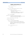
[:SOURce]:PM[1|2]:SENSitivity
Syntax
Form
Description
[:SOUR]:PM[1|2]:SENS
Set
Sets jitter modulation sensitivity.
You now have to apply an external source (–0.5 V … 0.5 V max)
for jitter modulation to the Delay Control Input at the instrument’s
front panel:
• If you apply a source of 500 mV, the signal delay will be
increased by 250 ps/25 ps.
• If you apply a source of –500 mV, the signal delay will be
decreased by 250 ps/25 ps.
Between –500 mV and +500 mV, the signal delay
increases/decreases lineally to the Delay Control Input, for
example, a source of +200 mV results in a delay of 250 ps/V * 200
mV = 50 ps.
Parameter
25ps|250ps
Jitter modulation is turned on with fixed sensitivity of 50 ps/V or
500 ps/V.
*RST value
Example
25 ps
Set the delay control input to 25 ps.
[:SOUR]:PM[1|2]:SENS 25ps
Agilent 81133A/81134A Pulse Generator Programming Guide, March 2007
59
SCPI Commands Reference
SOURce Commands
[:SOURce]:VOLTage[0|1|2][:LEVel]
[:IMMediate][:AMPLitude]
Syntax
Form
Description
[:SOUR]:VOLT[0|1|2][:LEV][:IMM][:AMPL][?]
Set & Query
Programs the amplitude of the output signal for the trigger output
and the channels.
Parameter
Numeric [uV|mV|V] |MIN|MAX
Value coupling
High = Offset + (Amplitude / 2)
Low = Offset – (Amplitude / 2)
Range coupling
*RST value
Offset
Trigger output (0): 100 mV
Channels 1 and 2: 100 mV
Specified limits
Trigger output (0): 50 mV... 2.0 V
Channels 1 and 2: 50 mV… 2.0 V
Absolute limits
Trigger output (0): 2.0 V
Channels 1 and 2: 2.0 V
Example
Set Trigger Output amplitude to 1 V.
:VOLT0 1V
60
Agilent 81133A/81134A Pulse Generator Programming Guide, March 2007
SOURce Commands
SCPI Commands Reference
[:SOURce]:VOLTage[0|1|2][:LEVel]
[:IMMediate]:OFFSet
Syntax
Form
Description
[:SOUR]:VOLT[0|1|2][:LEV][:IMM]:OFFS[?]
Set & Query
Programs the offset of the output signal for the trigger output and
the channels.
Parameter
Numeric [uV|mV|V] |MIN|MAX
Value coupling
High = Offset + (Amplitude / 2)
Low = Offset – (Amplitude / 2)
Range coupling
*RST value
Amplitude
Trigger output (0): 0 V
Channels 1 and 2: 0 V
Specified limits
Trigger channel (0): –1.975 V … +2.975 V
Channels 1 and 2: –1.975 V … +2.975 V
Example
Set Trigger Output offset to –100 mV.
:VOLT0:OFFS -100MV
Agilent 81133A/81134A Pulse Generator Programming Guide, March 2007
61
SCPI Commands Reference
SOURce Commands
[:SOURce]:VOLTage[0|1|2][:LEVel]
[:IMMediate]:HIGH
Syntax
Form
Description
Parameter
Value coupling
[:SOUR]:VOLT[0|1|2][:LEV][:IMM]:HIGH[?]
Set & Query
Programs the high- level of the output signal for the trigger output
and the channels.
Numeric [uV|mV|V] |MIN|MAX
Amplitude = High – Low
Offset = (High – Low) / 2
Range coupling
*RST value
Low- level
Trigger channel (0): 0.1 V
Channels 1 and 2: 0.1 V
Specified limits
Trigger channel (0): –1.95 … +3.0 V
Channels 1 and 2: –1.95 ... +3.0 V
Absolute limits
Trigger output (0): –2.2 … +3.2 V
Channels 1 and 2: –2.2 … +3.2 V
Example
Set Channel 1 high- level to –200 mV.
:VOLT1:HIGH -200MV
62
Agilent 81133A/81134A Pulse Generator Programming Guide, March 2007
SOURce Commands
SCPI Commands Reference
[:SOURce]:VOLTage[0|1|2][:LEVel]
[:IMMediate]:LOW
Syntax
Form
Description
Parameter
Value coupling
[:SOUR]:VOLT[0|1|2][:LEV][:IMM]:LOW[?]
Set & Query
Programs the low- level of the output signal for the trigger output
and the channels.
Numeric [uV|mV|V] |MIN|MAX
Amplitude = High – Low
Offset = (High – Low) / 2
Range coupling
*RST value
High- level
Trigger channel (0): 0.0 V
Channels 1 and 2: 0.0 V
Specified limits
Trigger channel (0): –2.0 … +2.95 V
Channels 1 and 2: –2.0 … +2.95 V
Absolute limits
Trigger output (0): –2.2 … +3.2 V
Channels 1 and 2: –2.2 … +3.2 V
Example
Set Channel 1 low- level to –1 V.
:VOLT1:LOW -1V
Agilent 81133A/81134A Pulse Generator Programming Guide, March 2007
63
SCPI Commands Reference
SOURce Commands
[:SOURce]:VOLTage[0|1|2][:LEVel]
[:IMMediate]:TERM
Syntax
Form
Description
[:SOUR]:VOLT[0|1|2][:LEV][:IMM]:TERM[?]
Set & Query
Programs the termination voltage of the output signal for the
trigger output and the channels.
Parameter
Numeric [uV|mV|V]
*RST value
Trigger output (0): 0.0 V
Channels 1 and 2: 0.0 V
Specified limits
Trigger output (0): –2.0 V … +3.0 V
Channels 1 and 2: –2.0 V … +3.0 V
Example
Set Channel 1 termination voltage to 1 V.
:VOLT1:TERM 1V
[:SOURce]:VOLTage[1|2]:LIMit
[:AMPLitude]?
Syntax
Form
[:SOUR]:VOLT[1|2]:LIM[:AMPL]?
Query
Description
Reads the current setting of the amplitude limit. The result is only
valid if the “Limit to current levels” output mode is currently on
([:SOURce]:VOLTage[1|2]:LIMit:STATe ON).
*RST value
100 mV
Example
Read Channel 1 amplitude limit.
:VOLT1:LIM?
64
Agilent 81133A/81134A Pulse Generator Programming Guide, March 2007
SOURce Commands
SCPI Commands Reference
[:SOURce]:VOLTage[1|2]:LIMit:OFFSet?
Syntax
Form
Description
*RST value
Example
[:SOUR]:VOLT[1|2]:LIM:OFFS?
Query
This command reads the current setting of the offset limit. The
result is only valid if “Limit to current levels” output mode is
currently on ([:SOURce]:VOLTage[1|2]:LIMit:STATe ON).
0 mV
Read Channel 1 offset limit.
:VOLT1:LIM:OFFS?
[:SOURce]:VOLTage[1|2]:LIMit:HIGH?
Syntax
Form
Description
*RST value
Example
[:SOUR]:VOLT[1|2]:LIM:HIGH?
Query
This command reads the current setting of the high- level limit. The
result is only valid if Limited output mode is currently on
([:SOURce]:VOLTage[1|2]:LIMit:STATe ON).
100 mV
Read Channel 1 high- level limit.
:VOLT1:LIM:HIGH?
[:SOURce]:VOLTage[1|2]:LIMit:LOW?
Syntax
Form
Description
*RST value
Example
[:SOUR]:VOLT[1|2]:LIM:LOW?
Query
This command reads the current setting of the low- level limit. The
result is only valid if “Limit to current values” mode is currently
on ([:SOURce]:VOLTage[1|2]:LIMit:STATe ON).
0 V
Read Channel 1 low- level limit.
:VOLT1:LIM:LOW?
Agilent 81133A/81134A Pulse Generator Programming Guide, March 2007
65
SCPI Commands Reference
SOURce Commands
[:SOURce]:VOLTage[1|2]:LIMit:STATe
Syntax
Form
Description
[:SOUR]:VOLT[1|2]:LIM:STAT[?]
Set & Query
Switches the “Limit to current values” output mode on or off.
When you switch on Limited output mode the current high- level
and low- level parameters are taken as limit values restricting the
available ranges of all output- level parameters. You cannot program
the output- levels beyond these temporary limits, until you switch
off Limited output mode. The limits apply whether you program
high/low levels or amplitude/offset levels.
Parameter
ON|OFF|1|0
*RST value
OFF
Example
Switch on Channel 1 Limited output mode.
:VOLT1:LIM:STAT ON
66
Agilent 81133A/81134A Pulse Generator Programming Guide, March 2007
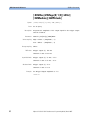
Status Handling Commands
SCPI Commands Reference
Status Handling Commands
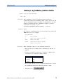
The IEEE 488.2 specification requires status registers that contain
information about the instrument’s hardware and firmware. For
the Agilent 81133A/81134A Pulse Generator, the status registers
have the following structure:
:QUEStionable:VOLTage
(not used)
0
1
2
+
15
:QUEStionable:FREQuency
Frequency Range
PLL Unlocked
Ext. Ref. Missing
0
1
2
Questionable Status
0
1
2
3
4
5
6
7
8
9
+
Standard Byte
*STB?
0
1
2
3
4
5
6
7
+
15
15
Operation Status
(not used)
:QUEStionable:MONotony
(not used)
0
1
2
+
0
1
2
+
15
15
Standard Event Status
*ESR?
Operation Complete
Query
Device Dep.
Execution
Command
Error
Error
Error
Error
Power On
0
1
2
3
4
5
6
7
+
Agilent 81133A/81134A Pulse Generator Programming Guide, March 2007
67
SCPI Commands Reference
Status Handling Commands
The following table shows the Agilent 81133A/81134A Pulse
Generator Status Handling Commands:
Command
Parameter
Description
:STATus
:OPERation
[:EVENt]?
Reads operation event register
:CONDition?
Reads operation condition register
:ENABle[?]
Numeric
Sets/reads operation enable register
:NTRansition[?]
Numeric
Sets/reads operation negativetransition filter
:PTRansition[?]
Numeric
Sets/reads operation positivetransition filter
:PRESet
Clears and presets status groups
:QUEStionable
[:EVENt]?
Reads questionable event register
:CONDition?
Reads questionable condition
register
:ENABle[?]
Numeric
Sets/reads questionable enable
register
:NTRansition[?]
Numeric
Sets/reads questionable negativetransition filter
:PTRansition[?]
Numeric
Sets/reads questionable positivetransition filter
:VOLTage
[:EVENt]?
Reads questionable voltage event
register
:CONDition?
Reads questionable voltage condition
register
:ENABle[?]
Numeric
Sets/reads questionable voltage
enable register
:NTRansition[?]
Numeric
Sets/reads questionable voltage
negative-transition register
:PTRansition[?]
Numeric
Sets/reads questionable voltage
positive-transition register
:FREQuency
[:EVENt]?
Reads questionable frequency event
register
:CONDition?
Reads questionable frequency
condition register
:ENABle[?]
68
Numeric
Sets/reads questionable frequency
enable register
Agilent 81133A/81134A Pulse Generator Programming Guide, March 2007
Status Handling Commands
SCPI Commands Reference
Command
Parameter
Description
:NTRansition[?]
Numeric
Sets/reads questionable frequency
negative-transition register
:PTRansition[?]
Numeric
Sets/reads questionable frequency
positive-transition register
:MONotony
[:EVENt]?
Reads questionable monotony event
register
:CONDition?
Reads questionable monotony
condition register
:ENABle[?]
Numeric
Sets/reads questionable monotony
enable register
:NTRansition[?]
Numeric
Sets/reads questionable monotony
negative-transition register
:PTRansition[?]
Numeric
Sets/reads questionable monotony
positive-transition register
Agilent 81133A/81134A Pulse Generator Programming Guide, March 2007
69
SCPI Commands Reference
Status Handling Commands
:STATus:OPERation
This command tree accesses the OPERation status group.
The OPERation status group is not used by the Agilent
81133A/81134A Pulse Generator, therefore this command tree is
redundant.
:STATus:PRESet
Syntax
Form
Description
:STAT:PRES
Event
This command
• clears all status group event- registers
• clears the error queue
• presets the status group enable, PTR, and NTR registers as
follows:
Status Group
Register
Preset Value
OPERation
ENABle
0000000000000000
PTR
0111111111111111
NTR
0000000000000000
ENABle
0000000000000000
PTR
0111111111111111
NTR
0000000000000000
ENABle
0111111111111111
PTR
0111111111111111
NTR
0000000000000000
ENABle
0111111111111111
PTR
0111111111111111
NTR
0000000000000000
ENABle
0111111111111111
PTR
0111111111111111
NTR
0000000000000000
QUEStionable
QUEStionable:VOLTage
QUEStionable:FREQuency
QUEStionable:MONotony
70
Parameter
–
*RST value
–
Agilent 81133A/81134A Pulse Generator Programming Guide, March 2007
Status Handling Commands
SCPI Commands Reference
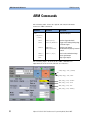
:STATus:QUEStionable
This command tree accesses the QUEStionable status group.
The QUEStionable status group contains the summary bits from
the QUEStionable:VOLTage, :FREQuency and MONotony status
group.
The following commands are used to access the registers within
the status group.
:STATus:QUEStionable[:EVENt]?
Syntax
Form
Description
:STAT:QUES[:EVEN]?
Query
Reads the event register in the QUEStionable status group.
Parameter
–
*RST value
–
:STATus:QUEStionable:CONDition?
Syntax
Form
:STAT:QUES:COND?
Query
Description
Reads the condition register in the QUEStionable status group.
NOTE
The Agilent 81133A/81134A Pulse Generator does not use this
condition register, therefore, this command is redundant.
Parameter
–
*RST value
–
:STATus:QUEStionable:ENABle
Syntax
Form
Description
:STAT:QUES:ENAB[?]
Set & Query
Sets or queries the enable register in the QUEStionable status
group.
Agilent 81133A/81134A Pulse Generator Programming Guide, March 2007
71
SCPI Commands Reference
Status Handling Commands
Parameter
Numeric
*RST value
–
Specified limits
0 … 32767
:STATus:QUEStionable:NTRansition
Syntax
Form
Description
NOTE
:STAT:QUES:NTRansition[?]
Set & Query
Sets or queries the negative- transition register in the QUEStionable
status group.
The Agilent 81133A/81134A Pulse Generator does not use the
transition registers of the QUEStionable status group, therefore,
this command is redundant.
Parameter
Numeric
*RST value
–
Specified limits
0 … 32767
:STATus:QUEStionable:PTRansition
Syntax
Form
Description
NOTE
Set & Query
Sets or queries the positive- transition register in the QUEStionable
status group.
The Agilent 81133A/81134A Pulse Generator does not use the
transition registers of the QUEStionable status group, therefore,
this command is redundant.
Parameter
Numeric
*RST value
–
Specified limits
72
:STAT:QUES:PTRansition[?]
0 … 32767
Agilent 81133A/81134A Pulse Generator Programming Guide, March 2007
Status Handling Commands
SCPI Commands Reference
:STATus:QUEStionable:VOLTage
This command tree accesses the QUEStionable:VOLTage status
group.
The QUEStionable:VOLTage status group monitors the currently
programmed output voltage levels against their specified ranges.
The following commands are used to access the registers within
the status group.
:STATus:QUEStionable:VOLTage[:EVENt]?
Syntax
Form
Description
:STAT:QUES:VOLT[:EVEN]?
Query
Reads the event register in the QUEStionable:VOLTage status
group.
Parameter
–
*RST value
–
:STATus:QUEStionable:VOLTage:CONDition?
Syntax
Form
Description
:STAT:QUES:VOLT:COND?
Query
Reads the condition register in the QUEStionable:VOLTage status
group.
Parameter
–
*RST value
–
:STATus:QUEStionable:VOLTage:ENABle
Syntax
Form
Description
:STAT:QUES:VOLT:ENAB[?]
Set & Query
Sets or queries the enable register in the QUEStionable:VOLTage
status group.
Parameter
Numeric
*RST value
–
Agilent 81133A/81134A Pulse Generator Programming Guide, March 2007
73
SCPI Commands Reference
Status Handling Commands
Specified limits
0 … 32767
:STATus:QUEStionable:VOLTage:NTRansition
Syntax
Form
Description
:STAT:QUES:VOLT:NTR[?]
Set & Query
Sets or queries the negative- transition register in the
QUEStionable:VOLTage status group.
Parameter
Numeric
*RST value
–
Specified limits
0 … 32767
:STATus:QUEStionable:VOLTage:PTRansition
Syntax
Form
Description
:STAT:QUES:VOLT:PTR[?]
Set & Query
Sets or queries the positive- transition register in the
QUEStionable:VOLTage status group.
Parameter
Numeric
*RST value
–
Specified limits
0 … 32767
:STATus:QUEStionable:FREQuency
This command tree accesses the QUEStionable:FREQuency status
group.
The QUEStionable:FREQuency status group monitors the currently
programmed frequency against the specified range, detects if the
PLL in unlocked and indicates if there is a valid signal at the time
base external input.
The following commands are used to access the registers within
this status group.
74
Agilent 81133A/81134A Pulse Generator Programming Guide, March 2007
Status Handling Commands
SCPI Commands Reference
:STATus:QUEStionable:FREQuency[:EVENt]?
Syntax
Form
Description
:STAT:QUES:FREQ[:EVEN]?
Query
Reads the event register in the QUEStionable:FREQency status
group.
Parameter
–
*RST value
–
:STATus:QUEStionable:FREQuency:CONDition?
Syntax
Form
Description
:STAT:QUES:FREQ:COND?
Query
Reads the condition register in the QUEStionable:FREQency status
group.
Parameter
–
*RST value
–
:STATus:QUEStionable:FREQuency:ENABle
Syntax
Form
Description
:STAT:QUES:FREQ:ENAB[?]
Set & Query
Sets or queries the enable register in the QUEStionable:FREQency
status group.
Parameter
Numeric
*RST value
–
Specified limits
0 … 32767
Agilent 81133A/81134A Pulse Generator Programming Guide, March 2007
75
SCPI Commands Reference
Status Handling Commands
:STATus:QUEStionable:FREQuency:NTRansition
Syntax
Form
Description
:STAT:QUES:FREQ:NTR[?]
Set & Query
Sets or queries the negative- transition register in the
QUEStionable:FREQency status group.
Parameter
Numeric
*RST value
–
Specified limits
0 … 32767
:STATus:QUEStionable:FREQuency:PTRansition
Syntax
FormForm
Description
:STAT:QUES:FREQ:PTR[?]
Set & Query
Sets or queries the positive- transition register in the
QUEStionable:FREQency status group.
Parameter
Numeric
*RST value
–
Specified limits
0 … 32767
:STATus:QUEStionable:MONotony
This command tree accesses the QUEStionable:MONotony status
group.
The QUEStionable:MONotony status group monitors the frequency,
width, delay and amplitude parameters. The range of these
parameters is made up of several internal ranges and when the
parameter moves from one internal range to the next a
discontinuity can occur. For example, increasing the frequency at a
range boundary could cause the actual output frequency to
decrease slightly. The range boundaries also vary with temperature,
and a significant temperature change could cause the instrument
to move to the next range in order to maintain the current
parameter within specification.
76
Agilent 81133A/81134A Pulse Generator Programming Guide, March 2007
Status Handling Commands
SCPI Commands Reference
When a parameter range change occurs, the corresponding bit in
the QUEStionable:MONotony status event register is set to indicate
that the output signal may not vary monotonically with the
programmed parameter value.
The following commands are used to access the registers within
the status group.
:STATus:QUEStionable:MONotony[:EVENt]?
Syntax
Form
Description
:STAT:QUES:MON[:EVEN]?
Query
This command reads the event register in the
QUEStionable:MONotony status group.
Parameter
–
*RST value
–
:STATus:QUEStionable:MONotony:CONDition?
Syntax
Form
Description
NOTE
:STAT:QUES:MON:COND?
Query
This command reads the condition register in the
QUEStionable:MONotony status group.
The Agilent 81133A/81134A Pulse Generator does not use the
condition register of the QUEStionable:MONotony status group,
therefore, this command is redundant.
Parameter
–
*RST value
–
Agilent 81133A/81134A Pulse Generator Programming Guide, March 2007
77
SCPI Commands Reference
Status Handling Commands
:STATus:QUEStionable:MONotony:ENABle
Syntax
Form
Description
:STAT:QUES:MON:ENAB[?]
Set & Query
Sets or queries the enable register in the QUEStionable:MONotony
status group.
Parameter
Numeric
*RST value
–
Specified limits
0 … 32767
:STATus:QUEStionable:MONotony:NTRansition
Syntax
Form
Description
NOTE
:STAT:QUES:MON:NTR[?]
Set & Query
Sets or queries the negative- transition register in the
QUEStionable:MONotony status group.
The Agilent 81133A/81134A Pulse Generator does not use the
transition registers of the QUEStionable:MONotony status group,
therefore, this command is redundant.
Parameter
Numeric
*RST value
–
Specified limits
0 … 32767
:STATus:QUEStionable:MONotony:PTRansition
Syntax
Form
Description
78
:STAT:QUES:MON:PTR[?]
Set & Query
This command sets or queries the positive- transition register in
the QUEStionable:MONotony status group.
Agilent 81133A/81134A Pulse Generator Programming Guide, March 2007
SYSTem Commands
SCPI Commands Reference
NOTE
The Agilent 81133A/81134A Pulse Generator does not use the
transition registers of the QUEStionable:MONotony status group,
therefore, this command is redundant.
Parameter
Numeric
*RST value
–
Specified limits
0 … 32767
SYSTem Commands
The following table shows the Agilent 81133A/81134A Pulse
Generator SYSTem Commands:
Command
Parameter
Description
:SYSTem
:ERRor?
:KEY[?]
Reads error queue
Numeric
:PRESet
:SET[?]
Simulates key press or reads key
queue
*RST without changing display state
Block data
:VERSion?
Sets/reads complete instrument
setting
Reads SCPI compliance version
:COMMunicate
:LAN
[:SELF]
:ADDRess
String
Sets/reads instrument's LAN
address. String format is A.B.C.D
with A,B,C,D is number between 1
and 255
:SMASk
String
Sets/reads subnet mask of current
LAN. String format is similar to
:ADDR
:DGATeway
String
Sets/reads default Gateway for the
instrument. String format is similar
to :ADDR
Agilent 81133A/81134A Pulse Generator Programming Guide, March 2007
79
SCPI Commands Reference
SYSTem Commands
Command
Parameter
Description
:HADDRess
String
Set/read host LAN address for the
instrument. This setting is important
for FTP transfer
:NAME
alphanumeric Sets the LAN name for the
instrument
:DHCP
1|0|ON|OFF
Enables/disables DHCP
configuration
Numeric
Sets/reads GPIB bus No. A value
between 0 to 30 is required
:GPIB
[:SELF]
:ADDR
:COMMunicate:GPIB[:SELF]:ADDR
:COMMunicate::LAN[:SELF]:ADDRess
:COMMunicate::LAN[:SELF]:DHCP
:COMMunicate::LAN[:SELF]:SMASk
:COMMunicate::LAN[:SELF]:DGATeway
80
Agilent 81133A/81134A Pulse Generator Programming Guide, March 2007
SYSTem Commands
SCPI Commands Reference
:SYSTem:ERRor?
Syntax
Form
Description
:SYST:ERR?
Query
This command is used to read the Agilent 81133A/81134A Pulse
Generator error queue. The Agilent 81133A/81134A Pulse
Generator error queue can store up to 32 error codes on a firstin- first- out basis. When you read the error queue, the error
number and associated message are put into the instrument’s
output buffer.
If the error queue is empty, the value 0 is returned, meaning No
Error. If the queue overflows at any time, the last error code is
discarded and replaced with –350 meaning Queue Overflow.
Refer to “Troubleshooting” on page 97 for a list of the error
messages.
Parameter
–
*RST value
–
:SYSTem:PRESet
Syntax
Form
Description
:SYST:PRES
Event
This command is equivalent to *RST, except that there is no change
to the :DISPlay[:WINDow][:STATe]. Use this command instead of *RST
if you want the display to remain switched off during program
execution.
Parameter
–
*RST value
–
Agilent 81133A/81134A Pulse Generator Programming Guide, March 2007
81
SCPI Commands Reference
SYSTem Commands
:SYSTem:SET
Syntax
:SYST:SET[?]
Form
Set & Query
Description
In query form, the command reads a block of data containing the
instrument’s complete setup. The setup information includes all
parameter and mode settings, but does not include the contents of
the instrument setting memories, the status group registers or the
:DISPlay[:WINDow][:STATe]. The data is in a binary format, not
ASCII, and cannot be edited.
In set form, the block data must be a complete instrument setup
that was produced with the query form of this command.
Parameter
Block data
:SYSTem:VERSion?
Syntax
Form
82
:SYST:VERS?
Query
Description
This command reads the SCPI revision to which the instrument
complies.
*RST value
–
Agilent 81133A/81134A Pulse Generator Programming Guide, March 2007
SYSTem Commands
SCPI Commands Reference
:SYSTem:COMMunicate:LAN[:SELF]:DHCP
Syntax
Form
Description
:SYST:COMM:LAN[:SELF]:DHCP
Set
Enables/disables the DHCP.
• DHCP enabled
If DHCP is enabled, the instrument will request its own LAN
settings from the network. You only need to specify the LAN
name with “:SYSTEM:COMMunicate:LAN[:SELF]:NAME” on
page 83.
• DHCP disabled
If DHCP is disabled, you have to set the instrument IP address,
subnet mask, gateway and host address with:
– “:SYSTem:COMMunicate:LAN[:SELF] :ADDRess” on page 84
– “:SYSTem:COMMunicate:LAN[:SELF] :SMASk” on page 84
– “:SYSTem:COMMunicate:LAN[:SELF] :DGATeway” on page 85
Parameter
1|0|ON|OFF
*RST value
–
Example
Disable DHCP:
:SYST:COMM:LAN[:SELF]:DHCP OFF
:SYSTEM:COMMunicate:LAN[:SELF]:NAME
Syntax
Form
Description
:SYST:COMM:LAN[:SELF]:NAME <LAN name>
Set
Sets the LAN name. This command is only necessary for DHCP.
Parameter
alphanumeric
*RST value
–
Example
:SYST:COMM:LAN:NAME PP81134A01
Agilent 81133A/81134A Pulse Generator Programming Guide, March 2007
83
SCPI Commands Reference
SYSTem Commands
:SYSTem:COMMunicate:LAN[:SELF]
:ADDRess
Syntax
Form
Description
NOTE
:SYST:COMM:LAN[:SELF]:ADDR[?]
Set & Query
Sets the instrument's IP address.
This parameter must only be set if DHCP is not available. See
“:SYSTem:COMMunicate:LAN[:SELF]:DHCP” on page 83.
Parameter
String <no>.<no>.<no>.<no> in quotes, where <no> is in the range 1
… 255.
*RST value
–
Example
:SYST:COMM:LAN:ADDR "150.215.17.9"
:SYSTem:COMMunicate:LAN[:SELF]
:SMASk
Syntax
Form
Description
NOTE
Set & Query
Sets the instrument’s subnet mask.
This parameter must only be set if DHCP is not available. See
“:SYSTem:COMMunicate:LAN[:SELF]:DHCP” on page 83.
Parameter
String <no>.<no>.<no>.<no> in quotes, where <no> is in the range 0
… 255.
*RST value
–
Example
84
:SYST:COMM:LAN[:SELF]:SMAS[?]
:SYST:COMM:LAN:SMAS "255.255.240.000"
Agilent 81133A/81134A Pulse Generator Programming Guide, March 2007
SYSTem Commands
SCPI Commands Reference
:SYSTem:COMMunicate:LAN[:SELF]
:DGATeway
Syntax
Form
Description
NOTE
:SYST:COMM:LAN[:SELF]:DGAT[?]
Set & Query
Sets the instrument’s gateway.
This parameter must only be set if DHCP is not available. See
“:SYSTem:COMMunicate:LAN[:SELF]:DHCP” on page 83.
Parameter
String <no>.<no>.<no>.<no> in quotes, where <no> is in the range 1
… 255.
*RST value
–
Example
:SYST:COMM:LAN:DGAT "150.215.001.001"
:SYSTem:COMMunicate:GPIB[:SELF]:ADDR
Syntax
Form
Description
:SYST:COMM:GPIB[:SELF]:ADDR[?]
Set & Query
Sets/reads the instrument’s GPIB bus number.
Parameter
Numeric
*RST value
13
Example
:SYST:COMM:GPIB[:SELF]:ADDR 15
Agilent 81133A/81134A Pulse Generator Programming Guide, March 2007
85
SCPI Commands Reference
TRIGger Commands
TRIGger Commands
The following table shows the Agilent 81133A/81134A Pulse
Generator TRIGger Commands:
Command
Parameter
Description
:SOURce[?]
IMMediate|EXTernal
|
REFerence|
IDIRect|
EDIRect
Sets/reads timebase mode
internal, external, external 10 MHz
reference, internal direct and
external direct
:TERM[?]
Numeric [uV|mV|V]
Sets/reads termination voltage
:TERMSTATe[?]
ON|OFF
Sets/reads termination state.
:TRIGger
Defines whether the external clock
input (Clock In) connector is AC or
DC terminated
:TRIG:SOUR[?]
:TRIG::TERM[?]
:TRIG::TERMSTATe[?]
86
Agilent 81133A/81134A Pulse Generator Programming Guide, March 2007
TRIGger Commands
SCPI Commands Reference
:TRIGger:SOURce
Syntax
Form
Description
:TRIG:SOUR[?]
Set & Query
This command is used to switch the timebase mode between
Internal (IMMediate) and External (EXTernal).
With :TRIGger:SOURce IMMediate (internal timebase) the frequency
(or period) is controlled with the [:SOURce]:FREQuency (or
[:SOURce][:PULSe]:PERiod) command.
With :TRIGger:SOURce EXTernal, the frequency (or period) is
controlled by the external signal applied to the external clock
input connector (Clock In).
Parameter
IMMediate|EXTernal|REFerence|IDIRect|EDIRect
• IMMediate
The clock is derived from the internal oscillator.
• EXTernal
Enables the external clock input (Clock In) to accept an external
clock signal that forms the time base. The frequency is measured
once by selecting the Measure function from the user interface
or as a remote SCPI command (:MEASure:FREQuency?).
This value is then used to calculate frequency- dependent values,
like the pulse width or the phase (available at the Channel
page).
• REFerence
Enables the external clock input (Clock In) to apply a 10 MHz
reference clock. This clock is used as a reference for all timing
parameters.
• IDIRect|EDIRect
The direct modes allow changes of frequency without dropouts
in the range of 1:2. They are used for applications (precise clock
source), where dropouts would make a measurement impossible,
for example, PLL frequency sweep and micro processor clock
sweep.
– IDIRect
Allows you to vary the clock derived from the internal
oscillator in the range of one octave.
Agilent 81133A/81134A Pulse Generator Programming Guide, March 2007
87
SCPI Commands Reference
TRIGger Commands
– EDIRect
Allows you to vary the frequency of the external clock signal
in the range of one octave.
Range switching occurs at the following frequency values:
• 1680 MHz
• 840 MHz
• 420 MHz
• 210 MHz
• 105 MHz
• 51.5 MHz
• 25.75 MHz
These values are based on 1680 MHz, subject to the frequency
divider.
*RST value
Example
IMMediate
Select the external timebase mode.
:TRIG:SOUR EXT
:TRIGger:TERM
Syntax
Form
Description
NOTE
:TRIG:TERM[?]
Set & Query
Sets/reads the termination voltage for the external clock input. See
“:TRIGger:SOURce” on page 87.
The termination voltage can only be specified if the Clock In
connector is DC terminated.
Parameter
Numeric [uV|mV|V]
*RST value
0 mV
Specified limits
Example
–2.0 V … 3.0 V
Set the termination voltage of the signal applied to the external
clock input to 1V.
:TRIG:TERM 1V
88
Agilent 81133A/81134A Pulse Generator Programming Guide, March 2007
TRIGger Commands
SCPI Commands Reference
:TRIGger:TERM:STATE[?]
Syntax
Form
Description
:TRIG:TERM:STATE[?]
Set & Query
Defines whether the external clock input connector (Clock In) is
AC or DC terminated.
Parameter
ON|OFF where ON = DC and OFF = AC terminated.
*RST value
OFF
Example
Set the coupling of the external clock input connector to DC.
:TRIG:TERM:STATE ON
Agilent 81133A/81134A Pulse Generator Programming Guide, March 2007
89
SCPI Commands Reference
ARM Commands
ARM Commands
The following table shows the Agilent 81133A/81134A Pulse
Generator ARM Commands:
Command
Parameter
:ARM
Description
External start input
[:SEQuence]
[:LAYer]
:LEVel
Numeric[mV|V]
Sets the trigger threshold
:SLOPe
POSitive|NEGative
Trigger set to leading/trailing edge
of external signal
:SOURce
IMMediate|
MANual|EXTernal
Sets the start input to
disabled/manual (by key)/external
started
:TERM[?]
Numeric [mV|V]
Sets/reads termination voltage
[:STARt]
Starts signal output
:STOP
Stops signal output
The following figure shows how the ARM commands are
implemented in the 81133A/81134A user interface.
:ARM[:SEQ][:LAY][:START]
:ARM[:SEQ][:LAY]:STOP
:ARM[:SEQ][:LAY]:SOURce
:ARM[:SEQ][:LAY]:SLOP
:ARM[:SEQ][:LAY]:LEV
:ARM[:SEQ][:LAY]:TERM[?]
90
Agilent 81133A/81134A Pulse Generator Programming Guide, March 2007
ARM Commands
SCPI Commands Reference
:ARM[:SEQuence][:LAYer]:LEVel
Syntax
Form
Description
NOTE
Parameter
:ARM[:SEQ][:LAY]:LEV
Set & Query
Specifies the threshold voltage for the external start signal.
The threshold can only be specified if the external start mode is
selected (“:ARM:SOURce EXT”).
Numeric [mV|V]
Specified limits
–2 V … 3.0 V
Absolute limits
–2.0 V … 3.0 V
*RST value
Example
100 mV
Sets the threshold voltage to 2.0 V.
:ARM:LEV 2.0 V
Agilent 81133A/81134A Pulse Generator Programming Guide, March 2007
91
SCPI Commands Reference
ARM Commands
:ARM[:SEQuence][:LAYer]:SLOPe
Syntax
Form
Description
NOTE
Parameter
:ARM[:SEQ][:LAY]:SLOP
Set & Query
Specifies whether the signal is generated at the rising or falling
edge of the external start signal.
The threshold can only be specified if the external start mode is
selected (“:ARM:SOURce EXT”).
POSitive|NEGative
• POSitive
The signal is generated at the rising edge.
• NEGative
The signal is generated at the falling edge.
*RST value
Example
POS
Specifies that the signal is generated at the falling edge.
:ARM:SLOP NEG
92
Agilent 81133A/81134A Pulse Generator Programming Guide, March 2007
ARM Commands
SCPI Commands Reference
:ARM[:SEQuence][:LAYer]:SOURce
Syntax
Form
Description
Parameter
:ARM[:SEQ][:LAY]:SOUR
Set & Query
Specifies when the generated signal is output immediately, by
manual start or depending on an external signal at the Start In
connector.
IMMediate|MANual|EXTernal
The instrument provides the following start modes:
• IMMediate
The generated signal is always available at the outputs (assumed
that the outputs are enabled).
• MANual
The generated signal is output after Start at the instrument
panel is pressed.
• EXTernal
Select this start mode to send the generated signal to the
outputs depending on the external signal applied at the Start In
connector.
You can define the following parameters that the external signal
must meet:
– Threshold (voltage)
Set the threshold with “:ARM[:SEQuence][:LAYer]:LEVel” on
page 91.
– Termination voltage
Set the termination voltage with
“:ARM[:SEQuence][:LAYer]:TERM” on page 94.
– Edge (rising/falling)
Set the edge with “:ARM[:SEQuence][:LAYer]:SLOPe” on
page 92.
*RST value
Example
IMMediate
Set the start mode to external.
:ARM:SOUR EXT
Agilent 81133A/81134A Pulse Generator Programming Guide, March 2007
93
SCPI Commands Reference
ARM Commands
:ARM[:SEQuence][:LAYer]:TERM
Syntax
Form
Description
Parameter
Specified limits
*RST value
Example
:ARM[:SEQ][:LAY]:TERM[?]
Set & Query
Sets/reads the termination voltage for the start input signal.
Numeric [mV|V]
–2.0 V … 3.0 V
0 mV
Set the termination voltage to 1 V.
:ARM:TERM 1V
:ARM[:SEQuence][:LAYer][:STARt]
Syntax
Form
Description
NOTE
:ARM[:SEQ][:LAY][STAR]
Event
Puts the instrument in armed mode. This means, that the
instrument waits for the selected edge to appear.
The instrument can only be put in armed mode if the external
start mode is selected (“:ARM:SOURce EXT”).
Parameter
–
*RST value
–
Example
Set the armed mode:
:ARM
94
Agilent 81133A/81134A Pulse Generator Programming Guide, March 2007
ARM Commands
SCPI Commands Reference
:ARM[:SEQuence][:LAYer]:STOP
Syntax
Form
Description
:ARM[:SEQ][:LAY]:STOP
Event
Deactivates the armed mode for the instrument.
Parameter
–
*RST value
–
Example
Deactivate the armed mode:
:ARM:STOP
Agilent 81133A/81134A Pulse Generator Programming Guide, March 2007
95
SCPI Commands Reference
96
ARM Commands
Agilent 81133A/81134A Pulse Generator Programming Guide, March 2007
Troubleshooting
This chapter provides basic troubleshooting tips that you can use if
the instrument is not performing as expected.
Error Generated
The instrument generates error messages as follows:
-221:Settings conflict:String describing the error
The string describing the error could be one of the following:
• "divider of channel [1|2] leads to a frequency below minimum
frequency"
This occurs if the frequency below one of the channels is set
below the minimum (15 MHz). This could happen if the
frequency is decreased or if the frequency divider is increased.
• "pulsewidth of channel [1|2] is too small"
May happen:
– If the frequency is decreased and the channel is in duty
mode, or
– if the signal mode is switched from NRZ to RZ or R1, or
– if clock mode is switched from internal/external direct to a
none direct mode
• "pulse width of channel [1|2] is too large"
May happen:
– If the frequency is increased and the channel is in duty mode,
or
– if the signal mode is switched from NRZ to RZ or R1, or
– if clock mode is switched from internal/external direct to a
none direct mode.
Agilent 81133A/81134A Pulse Generator Programming Guide, March 2007
97
Troubleshooting
• "delay of channel [1|2] below minimum"
May happen:
– If the frequency is decreased and the channel is in phase
mode, or
– if the square mode is switched from square to another mode,
or
– if clock mode is switched from internal/external direct to a
none direct mode.
• "delay of channel [1|2] above maximum"
May happen:
– If the frequency is increased and the channel is in phase
mode, or
– if the channel mode is switched from SQUARE to another
mode, or
– if clock mode is switched from internal/external direct to a
none direct mode.
• "amplitude of trigger is too small"
May happen:
– If the trigger high level is decreased, or
– if the low level is increased.
• "amplitude of channel [1|2] is too small"
May happen:
– If the channel high level is decreased, or
– if the low level is increased.
• "amplitude of trigger is too large"
May happen:
– If the trigger high level is increased, or
– if the low level is decreased.
• "amplitude of channel [1|2] is too large"
May happen
– If the channel high level is increased, or
– if the low level is decreased.
• "low level of trigger is below minimum"
May happen:
98
Agilent 81133A/81134A Pulse Generator Programming Guide, March 2007
Troubleshooting
– If the trigger amplitude is increased, or
– if the offset is decreased.
• "low level of channel [1|2] is below minimum"
May happen:
– If the channel amplitude is increased, or
– if the offset is decreased.
• "high level of trigger exceeds maximum"
May happen:
– If the trigger amplitude is increased, or
– if the offset is increased.
• "high level of channel [1|2] exceeds maximum"
May happen:
– If the channel amplitude is increased, or
– if the offset is increased.
• "high level of trigger is lower than low level"
May happen:
– If the trigger amplitude is set to a negative value, or
– if high level and low level are set in parallel by list of
semicolon- separated SCPI commands.
• "high level of channel [1|2] is lower than low level"
May happen:
– If the channel amplitude is set to a negative value, or
– if high level and low levels are set in parallel by list of
semicolon- separated SCPI commands.
Instrument not Operable via LAN
If the instrument cannot be programmed via LAN, make sure that
you have installed the latest Agilent I/O library on your computer.
Visit the Agilent web site for the newest version.
Agilent 81133A/81134A Pulse Generator Programming Guide, March 2007
99
Troubleshooting
100
Agilent 81133A/81134A Pulse Generator Programming Guide, March 2007
Differences between the 8133A and
the 81133A/81134A
This chapter shows you how to adapt a program written for the
8133A 3 GHz Pulse Generator to the new 81133A/81134A
instrument.
New Commands
The following tables list all commands new for the 81133A/81134A
pulse/pattern generator:
DIAGnostic Commands
“:DIAG:CHANnel[1|2]:PPERformance” on page 24
DIGital Commands
“:DIGital[1|2][:STIMulus]:PATTern:LENGth” on page 31
“:DIGital[1|2][:STIMulus]:SIGNal: CROSsover:[VALue]” on page 32
“:DIGital[1|2][:STIMulus]:SIGNal: CROSsover:[STATe]” on page 34
OUTPut Commands
“:OUTPut:CENTral” on page 44
SOURce Commands
“[:SOURce]:FUNCtion:MODe[1|2]” on page 51
“[:SOURce]:PM[1|2]” on page 59
“[:SOURce]:PM[1|2]:SENSitivity” on page 59
“[:SOURce]:VOLTage[0|1|2][:LEVel] [:IMMediate]:TERM” on page 64
Agilent 81133A/81134A Pulse Generator Programming Guide, March 2007
101
Differences between the 8133A and the 81133A/81134A
SYSTem Commands
“:SYSTem:COMMunicate:LAN[:SELF]:DHCP” on page 83
“:SYSTEM:COMMunicate:LAN[:SELF]:NAME” on page 83
“:SYSTem:COMMunicate:LAN[:SELF] :ADDRess” on page 84
“:SYSTem:COMMunicate:LAN[:SELF] :SMASk” on page 84
“:SYSTem:COMMunicate:LAN[:SELF] :DGATeway” on page 85
“:SYSTem:COMMunicate:GPIB[:SELF]:ADDR” on page 85
TRIGger Commands
“:TRIGger:TERM” on page 88
“:TRIGger:TERM:STATE[?]” on page 89
ARM Commands
“:ARM[:SEQuence][:LAYer]:LEVel” on page 91
“:ARM[:SEQuence][:LAYer]:SLOPe” on page 92
“:ARM[:SEQuence][:LAYer]:SOURce” on page 93
“:ARM[:SEQuence][:LAYer]:TERM” on page 94
“:ARM[:SEQuence][:LAYer][:STARt]” on page 94
“:ARM[:SEQuence][:LAYer]:STOP” on page 95
Same Commands with Internal
Change
The following tables list all commands that have been changed
internally due to new 81133A/81134A functionality:
Common Commands (see “Common Commands” on page 19)
*RCL
*SAV
DIGital Commands
“:DIGital[1|2][:STIMulus]:PATTern[:DATa]” on page 27
SOURce Commands
“[:SOURce]:FUNCtion[:SHAPe]” on page 50
102
Agilent 81133A/81134A Pulse Generator Programming Guide, March 2007
Differences between the 8133A and the 81133A/81134A
Obsolete Commands
The following tables list all commands that no longer exist for the
81133A/81134A pulse/pattern generator:
DIAGnostic Commands
:DIAG:CHANnel[1|2]:CABLecomp
:DIAG:CHANnel[1|2]:SMOothshape
:DIAG:TEMPCAL
MEASure Commands
:MEASure:TEMPerature?
SOURce Commands
[:SOURce]:FUNCtion:SOURce[?]
[:SOURce]:FUNCtion:BURSTcount
[:SOURce]:FUNCtion:RBURSTcount
SYSTem Commands
:SYSTem:KEY[?]
TRIGger Commands
:TRIGger:[START]
:TRIGger:STOP
Agilent 81133A/81134A Pulse Generator Programming Guide, March 2007
103
Copyright Agilent Technologies 2007
Printed in Germany March 2007
5988-7402EN
sA