1
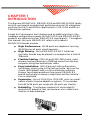
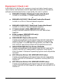
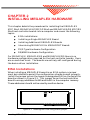
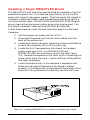
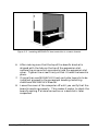
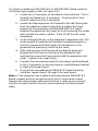
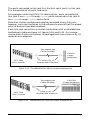
Hardware
Reference
Manual
MEGAPLEX
Serial I/O Subsystems
for
ISA/EISA BUS SYSTEMS:
MEGAPLEX MCC 24x4 Host Controller
MEGAPLEX CMX-24 Cluster Multiplexer
MEGAPLEX CMX-24D Cluster Multiplexer
MICRO CHANNEL BUS SYSTEMS:
MEGAPLEX/2 MCC 24x4 Host Controller
MEGAPLEX CMX-24 Cluster Multiplexer
MEGAPLEX CMX-24D Cluster Multiplexer
RS/6000 SYSTEMS:
MEGAPLEX/RS MCC 24x4 Host Controller
MEGAPLEX CMX-24 Cluster Multiplexer
MEGAPLEX CMX-24D Cluster Multiplexer
e
Copyright Notice
© 1991, 1992, 1993 Equinox Systems Inc. All rights reserved. Reproduction
without permission prohibited.
Trademarks
Equinox is a registered trademark of Equinox Systems, Inc. MEGAPORT and
MEGAPLEX are trademarks of Equinox Systems, Inc. XENIX is a registered
trademark of Microsoft Corp. UNIX is a registered trademark of AT&T.
Disclaimer
Equinox makes no representations or warranties with respect to the contents
hereof and specifically disclaims any implied warranties of merchantability or
fitness for any particular purpose. Information is subject to change without
notice and does not represent a commitment on the part of Equinox Systems
Inc.
FCC Notice
NOTE: The equipment has been tested and found to comply with the limits
for Class A digital devices, pursuant to Part 15 of the FCC rules. These limits
are designed to provide reasonable protection against harmful interference
when the equipment is operated in a commercial environment. This equipment generates, uses, and can radiate radio frequency energy and, if not
installed and used in accordance with the instruction manual, may cause
harmful interference to radio communications. Operation of this equipment in
a residential area is likely to cause harmful interference in which case the
user will be required to correct the interference at his own expense.
NOTE: This unit was tested with shielded cables on the peripheral devices.
Shielded cables must be used with the unit to insure compliance.
NOTE: The manufacturer is not responsible for any radio or TV interference
caused by unauthorized modifications to this equipment. Such modifications
could void the user’s authority to operate the equipment.
Document Reference Information
Document Title:
ii
MEGAPLEX Hardware Reference Manual
Part Number:
560050/B
Date:
March, 1993
Control:
Equinox Systems Inc., One Equinox Way
Sunrise, FL 33351, 954-746-9000, Fax: 954-746-9101
MEGAPLEX Hardware Reference Manual
Table of Contents
CHAPTER 1 - INTRODUCTION ............................................ 1
Applicability ...................................................................... 2
About This Manual ........................................................... 2
Equipment Check List ...................................................... 3
Software Support ............................................................. 5
References ...................................................................... 5
CHAPTER 2 - INSTALLING MEGAPLEX HARDWARE ....... 7
EISA Installations ............................................................. 7
Installing a Single MEGAPLEX Board .............................. 8
Installing Additional MEGAPLEX Boards ......................... 10
Intermixing MEGAPLEX & MEGAPORT Boards .............. 12
PS/2-Type Hardware Configuration ................................. 12
RS/6000 Hardware Configuration .................................... 14
CHAPTER 3 - MEGAPLEX CABLING .................................. 15
Cluster Multiplexer Link Wiring ........................................ 15
Wiring CMX-24 to Peripheral Devices.............................. 18
Device Wiring ......................................................... 19
Modular Cables ...................................................... 22
Modular Adaptors ................................................... 23
Wiring CMX-24D to Peripheral Devices ........................... 26
CMX-24D Connector Pinouts ................................. 27
Device Wiring ......................................................... 27
APPENDIX A - DOCUMENT CHANGE REQUEST ............... 29
APPENDIX B - TECHNICAL SUPPORT PROCEDURES ..... 31
Index ..................................................................................... 33
Table of Contents
iii
Hardware
Reference
Manual
MEGAPLEX
MEGAPLEX/2
MEGAPLEX/RS
Serial I/O Subsystems
e
PN 560050/B
Table of Contents
iv
CHAPTER 1
INTRODUCTION
The Equinox MEGAPLEX, MEGAPLEX/2 and MEGAPLEX/RS family
of multi-user boards provides high performance serial I/O subsystem
solutions for UNIX and XENIX applications in ISA, EISA and Micro
Channel bus systems.
Except for the computer bus interface and an additional step in the
hardware configuration process, MEGAPLEX/2 and MEGAPLEX/RS
products are identical to their MEGAPLEX counterparts. Throughout
this manual, the term MEGAPLEX refers to all products.
MEGAPLEX boards provide:
●
High Performance. All 96 ports are capable of running
38.4 Kbps on all ports simultaneously.
●
High Density. Up to 8 MEGAPLEX MCC 24x4 host
controller boards may be placed in a computer for a total of
768 ports.
●
Flexible Cabling. CMX-24 and CMX-24D cluster multiplexers may be placed up to 2500 feet away from the host
computer using two-twisted-pair cable.
●
Easy Installation. With Equinox's soft configuration
technology, simply plug in the host controller, wire up the
cluster multiplexers and run the installation software.
Answer two simple questions (how many MEGAPLEX
boards and where to memory map them) and the installation is completed.
●
Expansion. Up to 4 CMX-24 or CMX-24D units (or combination of both) may be added to a system. This provides
from 24 to 96 ports per single slot (24 ports per cluster).
●
Reliability. Transformer coupled link eliminates DC
ground shift potential that can cause errors in data transmission or board damage.
Introduction
1
Applicability
This manual is applicable to the following Equinox products:
●
MEGAPLEX MCC 24x4 Host Controller (ISA/EISA)
●
MEGAPLEX/2 MCC/2 24x4 Host Controller (Micro Channel)
●
MEGAPLEX/RS MCC/RS 24x4 Host Controller
●
MEGAPLEX CMX-24 Cluster Multiplexer (& accessories)
●
MEGAPLEX CMX-24D Cluster Multiplexer (& accessories)
About This Manual
This manual is a technical reference to the hardware installation and
operation of the MEGAPLEX family. It should be used in conjunction
with one of the MEGAPORT/MEGAPLEX device drivers discussed
below.
There is a considerable similarity in the installation and operation of
all MEGAPLEX products. Throughout this manual, the term
MEGAPLEX applies to all members of the family. Specific product
names, such as CMX-24 and CMX-24D, refer to issues which are
specific to that product. MEGAPLEX is essentially the same as the
MEGAPORT product as far as software and drivers are concerned.
Therefore, when the term MEGAPORT is used in this manual it
applies to both MEGAPORT and MEGAPLEX.
This manual is organized as follows:
Chapter 1 - Introduction
Introduces the MEGAPLEX family and lists the hardware and
software provided with a MEGAPLEX subsystem.
Chapter 2 - Installing MEGAPLEX Hardware
Chapter 2 describes how to install one or more MEGAPLEX,
MEGAPLEX/2 or MEGAPLEX/RS host controller boards in a
computer system.
Chapter 3 - MEGAPLEX Cabling
Chapter 3 describes the various cabling accessories used to
connect devices to CMX-24 and CMX-24D boards. Included are
wiring diagrams for building adaptors and cables.
2
MEGAPLEX Hardware Reference Manual
Equipment Check List
A MEGAPLEX 24-Port Kit contains a host controller board, one or
more cluster multiplexers and all applicable accessories (hardware,
software and documentation) required by the user's system.
●
MEGAPLEX MCC 24x4 Host Controller Board
Installs in an 80386- or 80486-based computer.
●
MEGAPLEX/2 MCC 24x4 Host Controller Board
Installs in a Micro Channel-based computer.
or
or
●
MEGAPLEX/RS MCC 24x4 Host Controller Board
Installs in a Micro Channel-based computer.
●
1" Interconnect cable (MEGAPLEX only)
Used to connect several MEGAPLEX host controllers
together.
●
EISA Jumper (MEGAPLEX only)
For EISA bus computers.
●
UNIX/XENIX Device Driver Kit
Contains the software and supporting manual required to
install MEGAPLEX subsystems in systems running the
UNIX System V 3.2/386 operating system, the 286 or 386
SCO XENIX operating system and compatible variants.
●
SVR4 STREAMS Device Driver Diskette
Contains the software and supporting manual required to
install MEGAPLEX subsystems in systems running the
UNIX System V Release 4 operating system and compatible
variants.
●
AIX-2 Device Driver Kit (MEGAPLEX/2 only)
Contains the software and supporting manual required to
install MEGAPLEX/2 boards in systems running IBM AIX
Version 2.
●
AIX-3 Device Driver Kit (MEGAPLEX/RS only)
Contains the software and supporting manual required to
install MEGAPLEX/RS boards in systems running IBM AIX
Version 3.
Introduction
3
●
1 to 4 CMX-24 (and/or CMX-24D) Cluster Multiplexers
Used to connect peripheral devices. Each CMX-24 and
CMX-24D cluster multiplexer is packaged with a wall
mounting kit, a 10' 4-wire modular link cable, 2 modular
wire adapters (for cable extension) and a wall-mounted
power transformer. The CMX-24D can be either wall or
rack mounted.
Different device driver kits with different part numbers are
provided with MEGAPLEX, MEGAPLEX/2 and
MEGAPLEX/RS (slight differences in the installation
process necessitate this for ease of installation). With
MEGAPLEX/2 host controller boards a PS/2 Option Diskette
is also included.
4
MEGAPLEX Hardware Reference Manual
Software Support
MEGAPLEX products are supported under various operating systems
by different software device drivers supplied by Equinox and other
vendors. The following device driver kits (including diskettes and
manuals) are available for both MEGAPORT and MEGAPLEX:
●
UNIX System V 3.2/386 operating system, SCO XENIX 286 or
386 operating system and compatible variants. Included with the
MEGAPLEX and MEGAPLEX/2 host controller boards.
●
UNIX System V Release 4 operating system and compatible
variants. Included with the MEGAPLEX and MEGAPLEX/2 host
controller boards.
●
IBM AIX Version 2.x operating system. Included with
MEGAPLEX/2 host controller boards.
●
IBM AIX Version 3.x operating system. Included with
MEGAPLEX/RS boards.
●
QNX and THEOS operating systems. Available in North
America from Florida Datamation, 1-800-642-5938. Available
elsewhere from Equinox.
Support for other operating systems may be available. For more
information, ask an authorized Equinox sales representative.
References
In addition to this manual and the appropriate Software Reference
Manual as provided in a device driver kit, readers may be interested
in the following publication:
For combined installations of MEGAPORT and
MEGAPLEX:
The MEGAPORT Hardware Reference Manual, part number
560047.
Introduction
5
6
MEGAPLEX Hardware Reference Manual
CHAPTER 2
INSTALLING MEGAPLEX HARDWARE
This chapter details the procedures for installing the MEGAPLEX
MCC 24x4, MEGAPLEX/2 MCC/2 24x4 and MEGAPLEX/RS MCC/RS
24x4 host controller boards into a computer and covers the following
topics:
●
EISA installations
●
Installing a Single MEGAPLEX Board
●
Installing Additional MEGAPLEX Boards
●
Intermixing MEGAPLEX & MEGAPORT Boards
●
PS/2-Type Hardware Configuration
●
RS/6000 Hardware Configuration
For MEGAPLEX, MEGAPLEX/2 and MEGAPLEX/RS there is no
hardware configuration required for the host controller boards; there
are no switches to set. The boards are entirely soft-configured during
the device driver installation.
EISA Installations
When installing a MEGAPLEX board in an EISA system, a jumper
must be installed to permit the configuration scheme to work properly.
Install the jumper across the two pins designated PA0 on the top of the
board as shown in Figure 2-1. This jumper forces the host controller
board to occupy addresses 0x340 and 0x341 in the computer memory.
These addresses should not be used by another device.
Figure 2-1. Installing the EISA configuration jumper
Installing MEGAPLEX Hardware
7
Installing a Single MEGAPLEX Board
The MEGAPLEX host controller board should be installed in the first
available computer slot. On a desktop type chassis, this is the first
empty slot closest to the power supply. The first empty slot closest to
the power supply facilitates installing additional boards using the 1inch interconnect cable. MEGAPLEX/2 and MEGAPLEX/RS boards
do not require the interconnect cable, so any slot may be used. The
first board installed is referred to as MEGAPLEX board #1.
Follow these steps to install the host controller board in a Personal
Computer:
1. Set the system unit power switch to OFF.
2. Disconnect the power cord and all other cables from the
back of the system unit.
3. Locate and remove the cover mounting screws and slide the
cover of the computer off (or lift the cover up).
4. Locate the first free expansion slot closest to the power
supply (see Figure 2-2). For MEGAPLEX/2 and
MEGAPLEX/RS, use any free or vacant slot (see Figure
2-3). Remove the expansion slot cover by first removing the
screw which holds the cover in place and then lifting off the
slot cover completely.
5. Insert the board firmly in the computer’s expansion slot.
Make sure the gold striped end of the board is seated
properly in the expansion slot groove and the bracket of the
board is in the groove which previously held the slot cover.
Figure 2-2. Installing MEGAPLEX host controller in desktop type chassis
8
MEGAPLEX Hardware Reference Manual
Figure 2-3. Installing MEGAPLEX host controller in a tower chassis
6. After making sure that the top of the board’s bracket is
aligned with the hole on the top of the expansion slot,
replace the screw which previously held the expansion slot
cover. Tighten the screw firmly so that it holds the board in
place.
7. If more than one MEGAPLEX host controller board is to be
installed, proceed to the paragraph heading Installing
Additional MEGAPLEX Boards.
8. Leave the cover of the computer off until you verify that the
board is working properly. This makes it easier to check the
board’s seating if a loose connection or a bad slot is later
suspected.
Installing MEGAPLEX Hardware
9
Installing Additional MEGAPLEX Boards
Additional MEGAPLEX host controller boards may be installed in a
computer. And, MEGAPLEX subsystems may be freely intermixed
with Equinox MEGAPORT products. (MEGAPLEX/2 subsystems
may be freely intermixed with MEGAPORT/2 and MEGAPLEX/RS
subsystems may be freely intermixed with MEGAPORT/RS.)
For Micro Channel (MEGAPLEX/2 [/RS] and MEGAPORT/2 [/RS])
boards, simply install the additional boards in empty slots in the
computer. There is no interconnect cable for Micro Channel boards.
Keep the following in mind when installing additional MEGAPLEX
host controller boards:
●
MEGAPLEX board #1 is always the board which is installed
in the slot closest to the power supply. When facing the
front of the computer, subsequent MEGAPLEX boards are
installed to the left of previously installed MEGAPLEX
boards (next to the non-component side of the installed
board).
●
Be sure MEGAPLEX board #1 is installed according to the
directions outlined in the previous paragraph under the
heading Installing a Single MEGAPLEX Board.
Figure 2-4. Installing additional MEGAPLEX or MEGAPORT boards
10
MEGAPLEX Hardware Reference Manual
To install an additional MEGAPLEX or MEGAPORT board, perform
the following procedure (refer to Figure 2-4):
1. Locate the J2 connector on the board to be installed. This is
located just below the J3 connector. Plug the short interconnect cable into the J2 connector.
2. Locate the free expansion slot located to the left (facing the
front of a desktop chassis computer) or below (for tower
chassis) of the previously installed MEGAPLEX board.
Remove the expansion slot cover by first removing the screw
which holds the cover in place. Then lift off the slot cover
completely.
3. Insert the board firmly in the computer’s expansion slot. Be
sure the gold striped end of the board is seated properly in
the slot’s groove and the bracket of the board is in the
groove which previously held the slot cover.
4. After making sure that the top of the board’s bracket is
aligned with the hole on the top of the expansion slot,
replace the screw which previously held the expansion slot
cover. Tighten the screw firmly.
5. Connect the interconnect cable on the newly installed board
to the J3 connector on the previously installed board located
to right of the new board.
6. If more than one additional MEGAPLEX board is being
installed, repeat steps 1 through 5 for each board.
Note: If the computer has trouble finding the second MEGAPLEX
board, suspect a faulty connection with the 1" interconnect cable.
Remove the interconnect cable and reinstall it making sure none of
the pins are bent and all the pins are enclosed by the interconnect
cable.
Installing MEGAPLEX Hardware
11
Intermixing MEGAPLEX & MEGAPORT Boards
MEGAPLEX subsystems may be freely intermixed with other
Equinox MEGAPORT products.
If a MEGAPLEX subsystem(s) is combined with any MEGAPORT
board(s) in a system, the MEGAPLEX subsystem(s) must be the first
board, physically, in the system. The interconnect cable supplied with
either board is connected in the same manner as when adding
another board (see Figure 2-4) in the system. To install the board(s),
perform the procedure outlined under the paragraph heading
Installing Additional MEGAPLEX Boards.
If a MEGAPLEX/2 subsystem(s) is combined with any MEGAPORT/2
board(s) in a system, any board may be placed in any slot in the
system; there is no interconnect cable. The same applies for
MEGAPLEX/RS and MEGAPORT/RS.
PS/2-Type Hardware Configuration
MEGAPORT/2 only
The following paragraphs apply to the IBM PS/2, the NCR 3000
Series and other similar Micro Channel Architecture computers. The
process described is essentially the same for each, although some
terminology may vary.
After installing the MEGAPLEX/2 host controller board, the computer
must be configured. The first time the machine is turned on with the
MEGAPLEX/2 installed, an error code of 165 appears and 2 beeps are
sounded after the RAM is counted. This error message indicates that
the configuration has been changed and the machine must be
reconfigured to recognize the MEGAPLEX/2.
Micro Channel machines require an Adapter Description File (ADF)
to automatically configure each peripheral device (adapter) installed.
The system identifies the adaptor by requesting a Programmable
Option Select (POS) ID from adapters installed in the computer. The
POS ID for the MEGAPLEX/2 is 6386. The corresponding ADF
(@6386.ADF) for the MEGAPLEX/2 containing the configuration
information for the board is provided on the MEGAPORT/2 Option
Diskette. This file must be copied to a backup of the Reference Diskette supplied with the computer. The steps for doing so are presented below.
12
MEGAPLEX Hardware Reference Manual
1. After receiving the 165 error message, the machine appears
to hang. Place the Reference Diskette in drive A: and press
F1. The screen clears and the banner screen appears. Press
Enter to continue. The following message is displayed:
Use Automatic Configuration (Y/N)? N
2. When answering no to the automatic configuration question, the following main menu appears:
Main
1.
2.
3.
4.
5.
6.
Menu
Learn about the computer.
Backup the Reference Diskette.
Set Configuration.
Set features.
Copy an option diskette.
Test the computer.
Because the MEGAPLEX/2 installation modifies the Reference Diskette, a backup of the diskette should be made. A
blank 1.44 MB diskette that is not write protected is required. Select option #2 and follow the instructions.
After completing the backup, store the original Reference
Diskette in a safe place. Continue using the backup.
3. Reboot the system using the backup Reference Diskette and
select option 5, Copy an option diskette, from the main
menu.
When asked, insert the new Option Diskette into drive A:.
The @6386.ADF file is copied into RAM. When asked, insert
the Reference Diskette into Drive A. The @6386.ADF file is
then appended to the Reference Diskette.
4. After the copy is finished and the display returns to the
main menu, select option 3 (Set configuration).
The set configuration menu appears on the display screen.
From this menu, select option 5, Run automatic configuration.
Set Configuration
1. View configuration.
2. Change configuration.
3. Backup configuration.
4. Restore configuration.
5. Run automatic configuration
Installing MEGAPLEX Hardware
13
5. After running the automatic configuration the system
CMOS contains the configuration of all adapters including
the MEGAPLEX/2. At this point, backup the new configuration by selecting option 3, Backup configuration, from the
set configuration menu.
6. The new configuration is copied onto the Backup Reference
Diskette. After the backup is complete, remove the Backup
Reference Diskette and store it and the original Reference
Diskette in a safe place. Exit the POS configuration utilities
and reboot the system from the hard disk. The system
should boot normally and not display the 165 error message.
The device driver is now ready to be installed under the
booted operating system as described in the Software
Reference Manual.
RS/6000 Hardware Configuration
MEGAPLEX/RS only
After installing MEGAPLEX/RS boards, the board must be configured
using the IBM SMIT facility. Information on how to do this is provided in the AIX-3 Software Reference Manual.
14
MEGAPLEX Hardware Reference Manual
CHAPTER 3
MEGAPLEX CABLING
This chapter applies equally to MEGAPLEX, MEGAPLEX/2 and
MEGAPLEX/RS.
The MEGAPLEX serial I/O subsystem supports a wide variety of
devices (both DCE and DTE), a range of cables from 4-wire RJ-11 to
10-wire RJ-45 and several different types of end connectors (DB-25,
DB-9 and RJ-11). With careful attention to the information presented
below, and the optional use of a breakout box, the correct pin connections for the installation should be assured.
All MEGAPLEX ports are of the CS or FM type and provide a standard RS-232 interface with modem control signals. FM types provide
full modem control signals.
To assist in wiring the MEGAPLEX subsystem, Equinox sells a
complete set of cabling accessories. See an Equinox Ordering Guide
for more information.
MEGAPLEX cabling (for all versions of MEGAPLEX) is divided into
two areas:
●
The host controller to cluster multiplexer link.
●
Cluster multiplexer wiring to terminals, modem and
printers.
Cluster Multiplexer Link Wiring
The link between the MCC 24x4 host controller and each CMX-24 and
CMX-24D cluster multiplexer is a 4-wire link. Data and control
signals on this cluster multiplexer link are encoded for high performance and are not available for any other purpose.
On the mounting bracket of the host controller are 4 modular link
jacks named A, B, C and D. Each link jack connects to a cluster
multiplexer with a two-twisted-pair cable. The 24 physical ports on
each cluster multiplexer are then mapped by the software device
driver into device names as appropriate to the specific driver selected.
MEGAPLEX Cabling
15
The ports connected to link jack A is the first set of ports, to link jack
B is the second set of ports, and so on.
For example, under the UNIX 3.2 device driver, ports connected to
link jack A are ttyaa through ttyax, ports connected to link jack B
are ttyba through ttybx, and so forth.
Note that cluster multiplexers may be connected to any link jack;
however, care must be taken in the software to ensure that the proper
set(s) of devices have been enabled.
Each link jack connects to a cluster multiplexer with unshielded twotwisted-pair cable as shown in Figures 3-1A and 3-1B. As a convenience, each cluster multiplexer is packaged with two crimp-on RJ-11
modular wire adaptors.
Two-twisted-pair
Cable (24 AWG)
CMX-24
Cluster
Multiplexer
MCC 24x4
Host Controller
Crimp-on RJ-11
Modular Wire Adaptors
Figure 3-1A. The MEGAPLEX CMX-24 cluster multiplexer link
Two-twisted-pair
Cable (24 AWG)
MCC 24x4
Host Controller
CMX-24D
Cluster Multiplexer
Crimp-on RJ-11
Modular Wire Adaptors
Figure 3-1B. The MEGAPLEX CMX-24D cluster multiplexer link
16
MEGAPLEX Hardware Reference Manual
When making cables, note that the RD(+) and RD(-) signals must be
twisted together, as are the TD(+) and TD(-) signals (see Figure 3-2).
With two-twisted-pair wiring, each cluster multiplexer can be located
up to 2500 feet from the host controller. Flat modular cable may also
be used for distances up to ten feet; such a ten foot cable is also
enclosed with each cluster multiplexer.
Figure 3-2. Cluster multiplexer link pinouts
MEGAPLEX Cabling
17
Wiring CMX-24 to Peripheral Devices
The CMX-24 cluster multiplexer provides standard RS-232 DTE
signals on 24, 10-pin, RJ-45 modular jacks, one for each device to be
connected. The pinouts for these jacks are shown in Figure 3-3.
Several items must be noted:
●
The jacks on the CMX-24 all face towards the center of the
product; thus the pinouts may seem to be opposite each
other. Refer to Figure 3-4 for the modular jack wiring
orientation.
●
Although the CMX-24 uses 10-pin modular jacks, the signal
pinouts have been arranged such that 4-, 6- or 8-wire
modular plugs may be used. Thus, as the receive and
transmit signals (and ground) are on the inner 4 wires, a 4wire connection may be made to data-only devices.
●
Either twisted-pair or flat modular cable may be used to
wire from the CMX-24 to a peripheral device.
Figure 3-3. CMX-24 RS-232 signals
18
MEGAPLEX Hardware Reference Manual
Figure 3-4. CMX-24 modular jack orientation
Device Wiring
Depending on the specific signal requirements of the system
peripheral devices, 3-, 4-, 7- or 9-wire connections can be made.
The figures below show these various options.
Three Wire Connection
For terminals and printers using XON/XOFF flow control.
CMX-24
Cluster
Multiplexer
DB-25 Pins
Figure 3-5. Pinouts for a terminal
MEGAPLEX Cabling
19
Four Wire Connection
For terminals and printers using pin 20 hardware flow control.
CMX-24
Cluster
Multiplexer
DB-25 Pins
Figure 3-6. Pinouts for a terminal or printer using hardware flow control
Seven Wire Connection
For full modem control signals (if RI and DSR are not required
for your application).
CMX-24
Cluster
Multiplexer
DB-25 Pins
Figure 3-7. Pinouts for a modem
20
MEGAPLEX Hardware Reference Manual
Nine Wire Connection
For full modem control signals.
CMX-24
Cluster
Multiplexer
DB-25 Pins
Figure 3-8. Pinouts for a modem
MEGAPLEX Cabling
21
Modular Cables
RJ-11 modular cable is the flat cable used for wiring telephones inside
of buildings. The cable is terminated at each end with an RJ-11
modular plug (connector) which is inserted into the modular jack of
an appropriate wiring module. Standard modular cables available
from Equinox or wiring distributors are reversing; that is the pins are
reversed on each end (so that pin 1 on one end is connected to pin 6 on
the opposite end, etc.). Figure 3-9 illustrates the signals passed
through modular cables when connected to a CMX-24 cluster multiplexer.
Figure 3-9. CMX-24 Modular cable signals
22
MEGAPLEX Hardware Reference Manual
Modular Adaptors
Modular adaptors convert modular jacks to DB-25 (RS-232) connectors. Use the following guide in conjunction with the documentation
provided with the computer equipment to select the correct modular
wiring accessories.
Part No.
Connector
6-wire modular adaptors
210036
DB-25 DCE male
210037
DB-25 DCE female
210026
DB-25 DTE male
210027
DB-25 DTE female
210038
DB-9 female
8-wire modular adaptors
210051
DB-25 DCE male
Connect To
terminals, printers,
etc.
terminals, ports, IBM
PC/XT, PS/2, etc.
modems or multiplexer
channels (female DCE)
male DCE devices
(non-standard devices)
IBM PC/AT serial port
210054
DB-25 DTE male
210055
DB-25 DCE female
terminals, printers,
etc.
modems or multiplexer
channels (female DCE)
male DTE device
210067
DB-25 DTE female
male DCE devices
210063
DB-9 female
IBM PC/AT serial port
Figures 3-10 and 3-11 show the internal wiring of the various modular adaptors.
When making modular adaptors, the 3K resistor shown may be
eliminated for use with most terminals. The resistor is used to loop
control signals back to the attached device when 4-wire cable is used
and pin 6 is not connected. When using 6-wire cable and there is a
voltage on pin 6 the resistor has no effect and the voltage on pin 6 is
passed through to the attached device.
MEGAPLEX Cabling
23
Figure 3-10. Six wire modular adaptors
24
MEGAPLEX Hardware Reference Manual
Figure 3-11. Eight wire modular adaptors
MEGAPLEX Cabling
25
Wiring CMX-24D to Peripheral Devices
The CMX-24D cluster multiplexer provides standard RS-232 DTE
signals on 24 DB-25 connectors, one for each connected device. Note
the following items:
●
The signals for all 24 connector jacks are identical to one
another as shown in Figure 3-12.
●
The jacks on the CMX-24D all face towards the bottom of
the product as shown in Figure 3-13. Connector jacks 1
through 4 are located from top to bottom on the left side of
the front panel and connector jacks 21 through 24 are
located from top to bottom on the right side of the front
panel.
●
Up to 10-conductor cable with DB-25 connectors may be
used to wire from the CMX-24D to a peripheral device.
Figure 3-12. CMX-24D RS-232 signals.
26
MEGAPLEX Hardware Reference Manual
Figure 3-13. CMX-24D DB-25 connector orientation.
CMX-24D Connector Pinouts
Figure 3-14 shows the pinouts for one CMX-24D cluster multiplexer
DB-25 female connector. All 24 connector jacks are identical.
Figure 3-14. CMX-24D Connector Pinouts
Device Wiring
Device wiring is dependent on the specific signal requirements of the
system peripheral devices. Cable connectors plugged into the CMX24D connector jacks must have a male DB-25 connector. The
connector on the opposite end of each cable should mate to the
peripheral device port (terminal, printer, personal computer or
modem).
MEGAPLEX Cabling
27
28
MEGAPLEX Hardware Reference Manual
APPENDIX A
DOCUMENT CHANGE REQUEST
At Equinox we are always striving to make our product manuals
accurate and easy to use. If you have an improvement to suggest or
find an error in this manual please let us know.
Manual: MEGAPLEX Hardware Reference Manual (560050/B)
Operating System and Version: __________________________________
Driver Version: _________________________________________________
Problem:
Solution:
What could be added or changed to make the manual better?
Name:
Title:
Company:
Phone:
Send to: Equinox Systems Inc.
ATTN: Customer Service
One Equinox Way
Sunrise, FL 33351-6709
954-746-9000, Fax: 954-746-9101
Document Change Request
29
30
MEGAPLEX Hardware Reference Manual
APPENDIX B
TECHNICAL SUPPORT PROCEDURES
Equinox Systems makes every effort to ensure that each MEGAPLEX
subsystem is of top quality. All MEGAPLEX subsystems are burned
in for 72 hours and must pass the test of continuous error-free data
flow on all ports simultaneously at 38.4 Kbps. If a problem arises with
this MEGAPLEX subsystem, please observe the following procedures
before calling Equinox:
●
Read the chapter of the hardware and software reference manuals
and any Release Notes describing the procedure currently being
performed.
●
Check the Equinox MEGAPORT Bulletin Board System. To
access the board, simply call 954-746-0282 with any speed modem
and use N-8-1 or E-7-1 parameters. Just follow the prompts to
answer a few identifying questions.
●
Contact the distributor from whom you purchased the board.
Equinox authorized distributors are fully trained on MEGAPORT
and MEGAPLEX products and are authorized to handle technical
support, service, returns and warranty claims.
●
If additional assistance is needed, after conferring with the
distributor or other point of purchase, call Equinox Technical
Support at 954-746-9000, Ext 322. Or, fax any problem report,
bug or question to Equinox at 954-746-9101. When calling, please
have the following information available:
Board Type:
Serial Number:
Date of Purchase:
Place of Purchase:
Operating System:
Operating System Version:
Device Driver Version:
Computer Make & Model:
Other Boards in Machine:
Description of Problem:
Technical Support Procedures
31
32
MEGAPLEX Hardware Reference Manual
Index
Symbols
D
560047
5
6386.ADF
12
Devices
non-standard
A
E
Adapter Description File
Adaptors
modular
23
ADF
12
AIX
5
Applicability
2
AT bus
1
AWG
16
12
31
C
Cable
modular
17, 18, 22
reversing
22
twisted-pair
16, 18
Cabling
15–23
Cabling accessories
15
Characteristics
1
Cluster multiplexer
link
15
CMX-24
connectors
18, 26
jacks
18, 26
CMX-24D
1, 2, 15
CMX-24D cluster multiplexer
link
16
CMX-24D connector jacks
27
CMX-24D Connector Pinouts
27
CS
15
Index
EISA
bus
1
jumper
3, 7
Enabling devices
16
Equipment checklist
2
F
B
Bracket
mounting
15
Breakout box
15
Bulletin Board System
23
Features
1
Florida Datamation
Flow control
19
hardware
20
software
20
Full modem control
5
21
H
Host controller
2
Hybrid installations
5
I
IBM PC/AT
23
IBM PC/XT
23
Installation
7, 7–14
MEGAPORT/2
14
Interconnect cable
3, 8, 12
Intermixing products
12
J
Jacks
link
15
33
L
R
Link
cluster multiplexer
Link cable
4
Link jacks
15
15
Reference Diskette
12
Reversing cable
22
RS-232
15
S
M
MCC 24x4 Host Controller
2
MEGAPLEX
12, 15
MEGAPLEX/2
12
MEGAPLEX/RS
1, 3, 8, 12, 14
MEGAPORT/2
12, 14
MEGAPORT/RS
14
Micro Channel
1, 12
Modem
20
Modem control signals
15
Modem wiring
19
Modular adaptors
23
Modular cable
17, 18, 22
Modular wire adaptors
4, 16
Mounting bracket
15
O
Option Diskette
Ordering Guide
12
15
P
SCO XENIX
5
SMIT
14
SVR4 STREAMS
3
T
Technical Support
31
Terminal devices
18, 26
Terminal wiring
19
Terminals
23
Terminology
2
THEOS
5
Twisted-pair cable
16, 18
U
UNIX STREAMS device driver
UNIX System V 3.2/386
5
UNIX System V Release 4
STREAMS
5
UNIX/XENIX device driver kit
3
3
W
Part numbers. See specific number
Peripheral devices
18, 26
Pin connections
15–23
Pinouts
18
POS ID
12
Power transformer
4
Printer wiring
19
Printers
23
Programmable Option Select
12
PS/2
12, 14, 23
Wall mount kit
4
X
XON/XOFF
19
Q
QNX
34
5
MEGAPLEX Hardware Reference Manual