1
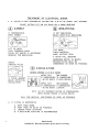
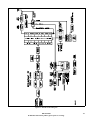
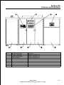
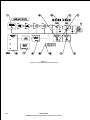
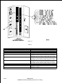
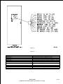
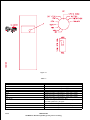
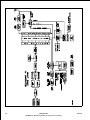
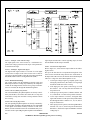
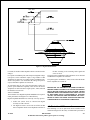
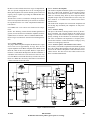
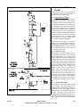
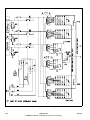
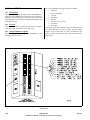
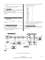
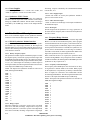
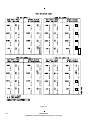
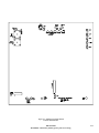
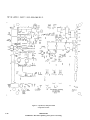
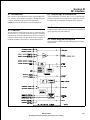
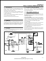
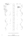
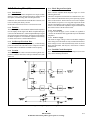
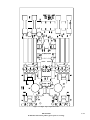
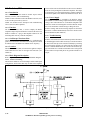
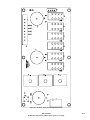
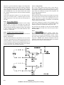
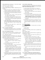
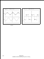
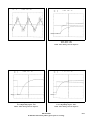
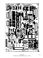
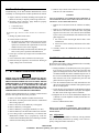
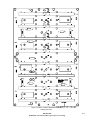
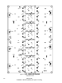
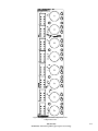
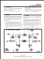
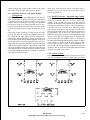
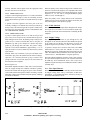
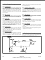
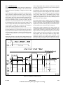
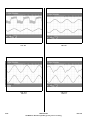
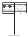
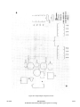
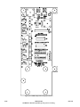
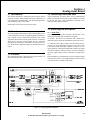
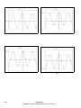
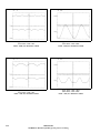
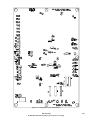
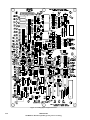
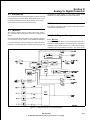
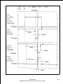
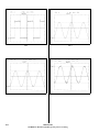
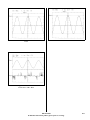
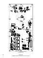
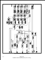
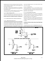
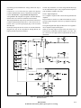
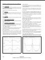
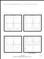
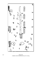
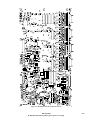
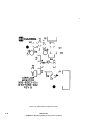
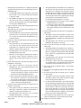
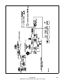
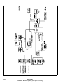
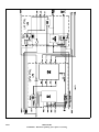
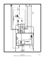
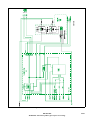
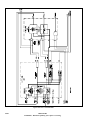
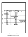
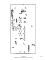
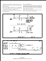
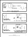
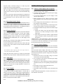
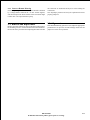
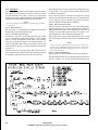
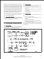
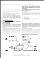
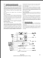
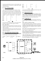
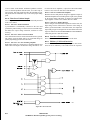
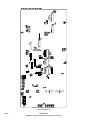
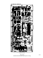
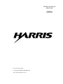
H.5 Block Diagram Description
amplifier which provides Forward/Reflected Power DC Samples
for front panel metering.
H.5.1 VSWR Detectors
Two types of VSWR detectors are provided: Antenna and Network VSWR. The purpose of the Antenna VSWR detector is to
sense an impedance change external to the transmitter. The
Network VSWR detector is for sensing a problem within the
output network. Both detectors are metered on the front panel,
plus initiate fault protection circuits in the event these values
exceed safe limits.
H.5.6 Modulation Monitor Sample
An RF Sample from the output is connected to Sample Equalization circuits. The AGC Control takes a sample of the Demodulated Audio to control the amount of Equalization so that the
External Modulation Monitor Sample is the same over the three
power levels.
H.5.2 ARC Detectors
Upper/Lower ARC Sensor Inputs are connected to their respective ARC Detectors and connected to the VSWR Test Logic
circuits. Either type fault is treated as a Network VSWR Fault.
H.5.7 Audio Detector
A Detector, Audio Filter, and Buffer amplifier are connected to
the Sample Equalization circuit and provides a Demodulated
Audio signal for testing purposes.
H.5.3 VSWR Logic
If either type VSWR is severe enough, VSWR Comparators will
generate signals that are applied to the VSWR Logic. Either input
will cause the VSWR Pulse Generator to produce an RF Mute
and activate the VSWR Synthesizer Sync Switchover function.
If VSWR is severe, the VSWR Foldback will produce Antenna/Network VSWR Faults that will cause power level Foldback, until a safe operating level is reached.
H.5.4 VSWR Self Test
When a VSWR Self Test Request is received, the VSWR Self
Test and VSWR Test Logic will purposely create both types of
Faults. The VSWR Test Status output is used to indicate the
condition of the protection circuits.
H.5.5 Directional Coupler
Antenna RF Voltage and RF Current samples from the Output
Sample board are applied to the Directional Coupler. These
samples are then applied to a Rectifier, Filter, and a Buffer
H.5.8 Air flow Monitor
An Air Flow Sensor in the Output Cabinet is connected to the Air
Flow Monitor. The Monitor can generate an Air Flow Foldback
Fault if the Sensor determines it is required.
H.5.9 Power Supplies
An unregulated +22VDC, -22VDC and +8VDC are regulated to
+15VDC, - 15VDC and +5VDC respectively to power circuits
on the board.
A Supply Fault Monitor monitors these supplies and can generate
a Supply Fault to the Controller.
H.6 Detailed Circuit Description
Refer to the schematic diagram for the Output Monitor board
(8435400851) for all descriptions in this section.
Figure H-2. VSWR Detector
H-2
888-2339-002
WARNING: Disconnect primary power prior to servicing.
02/17/04