1
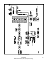
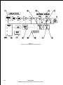
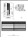
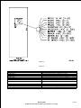
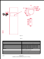
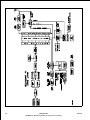
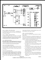
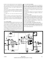
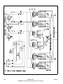
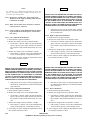
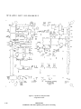
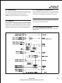
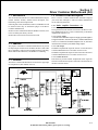
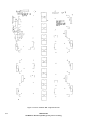
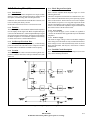
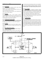
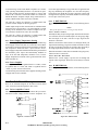
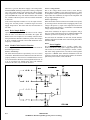
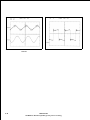
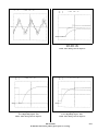
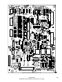
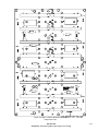
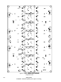
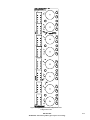
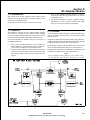
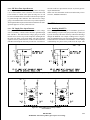
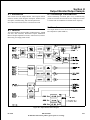
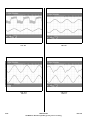
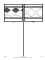
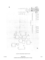
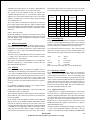
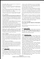
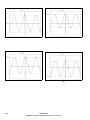
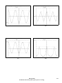
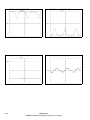
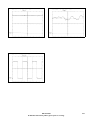
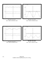
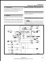
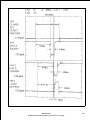
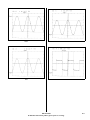
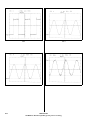
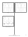
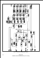
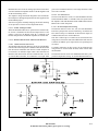
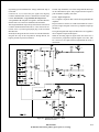
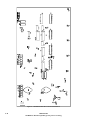
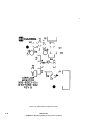
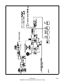
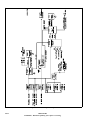
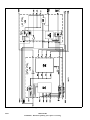
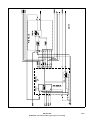
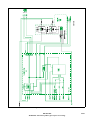
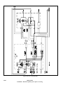
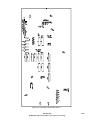
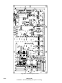
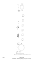
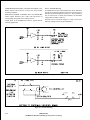
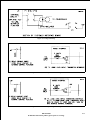
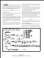
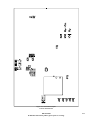
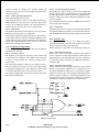
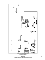
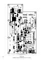
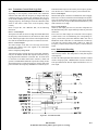
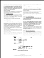
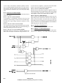
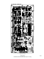
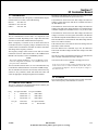
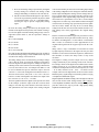
Figure 4-2. A/D-D/A
4.2.6.1.1
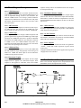
A/D Input - Audio And DC Voltage
The input signal to the A/D Converter is a combination of a
positive DC voltage (presented on the wiper of the potentiometer) and the audio input.
4.2.6.1.2
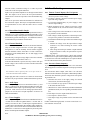
A/D Output - Digital Audio Signal
The digital audio signal consists of a stream of 12-bit digital
words on the 12 outputs of the A/D Converter. The 12 bits are
referred to as B1 through B12, where B1 is the Most Significant
Bit (MSB) and B12 is the Least Significant Bit (LSB).
4.2.6.2 Modulation Encoding
The control signals from the Modulation Encoder Latch and
ROM outputs turn the 160 Big Step and Binary RF Amplifiers
on and off. Each digital word consists of two groups of information to be encoded, B1 through B8 and B9 through B12.
4.2.6.2.1
Bits 9-12, Binary Step Control
The 4 fractional Binary Step RF Amplifiers are directly controlled by bits B9-B12, via Latches. B9 controls the 1/2 Step, B10
controls the 1/4 Step, B11 control the 1/8 Step, and B12 controls
the 1/16 Step.
4.2.6.2.2
Bits 1-8, Big Step Control
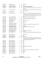
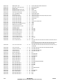
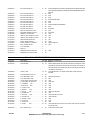
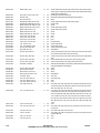
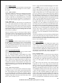
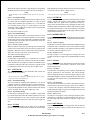
The 156 equal Big Step RF Amplifiers are directly controlled by
the bits B1-B8, via ROM #1 through ROM #20. The eight MSB
of the digital word address memory locations in each of the
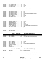
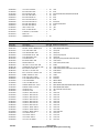
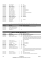
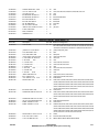
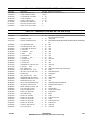
ROM’s, and the information stored in each ROM memory location turns on the required Big Step RF Amplifier. Each ROM has
4-4
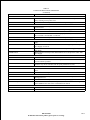
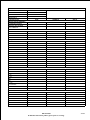
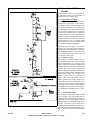
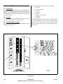
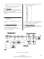
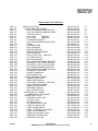
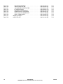
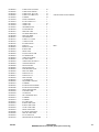
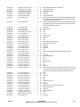
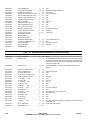
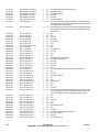
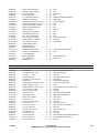
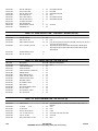
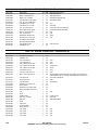
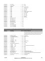
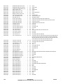
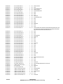
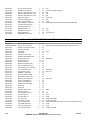
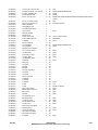
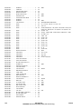
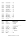
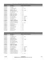
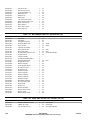
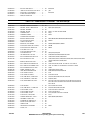
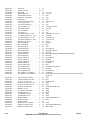
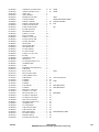
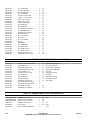
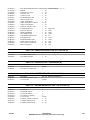
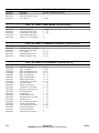
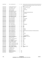
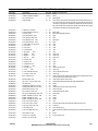
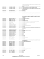
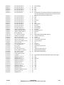
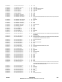
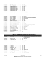
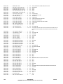
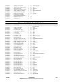
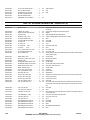
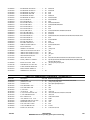
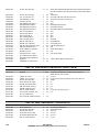
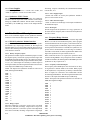
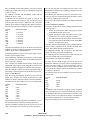
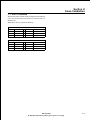
eight outputs and therefore controls eight Big Steps, the chart
lists the ROM # and the Steps Controlled.
4.2.6.2.3
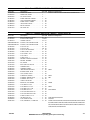
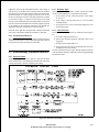
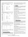
A/D Converter Output Chart
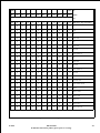
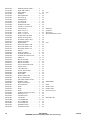
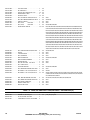
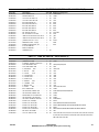
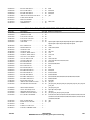
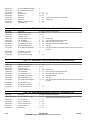
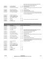
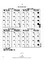
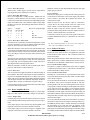
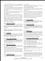
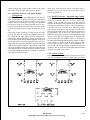
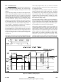
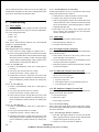
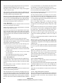
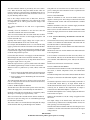
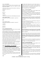
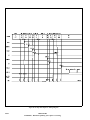
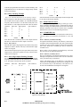
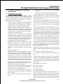
Refer to Figure 4-3, A/D Converter Output Chart for the following discussion.
The top of the chart lists the 12 outputs B12 through B1 of the
A/D Converter and the RF Amps turned “ON”. With 0VDC at
the input of the A/D Converter, the first line shows that all outputs
will be 0 or a logic low and no RF Amplifiers are on.
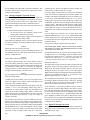
1. As the input voltage begins to go slightly positive (by
turning the potentiometer), B12 will be 1 or a logic high
and the latch will turn on the 1/16 Step.
2. If the input goes more positive, B12 will go to 0 and
B11 will be 1. The 1/16 Step will turn off and the 1/8
Step will turn on.
3. If the input goes more positive, both B12 and B11 will
be 1, and both the 1/16 and 1/8 Steps will be turned on.
4. As the input continues to increase, the digital audio
signal will continue to count up in a binary fashion until,
B12 through B9 will be 1 and the 1/16, 1/8, 1/4, and 1/2
Steps are all turned on.
5. If the input goes more positive, B12 through B9 will be
0 and the 1/16, 1/8, 1/4, and 1/2 Steps are all turned off.
B8 will be 1, and the first output from ROM #1 will turn
on Big Step #1.
888-2339-002
WARNING: Disconnect primary power prior to servicing.
12/16/03