1
Section H
Output Monitor/Output Sample
H.1 Introduction
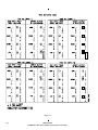
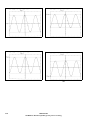
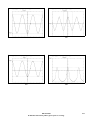
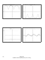
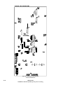
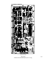
H.3 Oscilloscope Waveform Plots
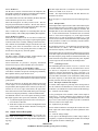
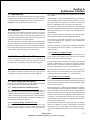
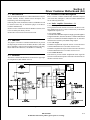
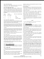
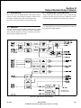
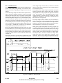
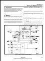
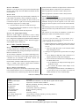
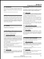
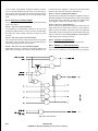
This section covers the Output Monitor board. Topics include
function, location, block diagram description, detailed circuit
description, troubleshooting, and removal/replacement.
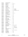
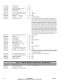
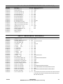
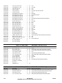
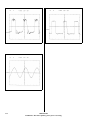
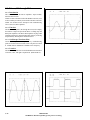
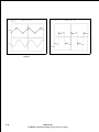
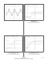
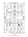
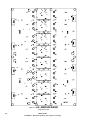
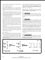
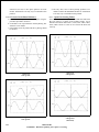
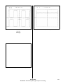
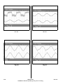
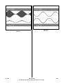
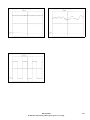
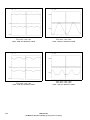
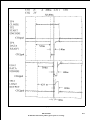
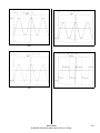
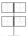
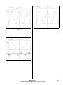
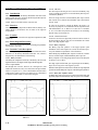
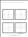
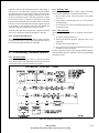
Actual oscilloscope waveform plots of key troubleshooting
points are located at the end of this section. All plots were taken
at 100 kW with no modulation at 585 kHz carrier frequency.
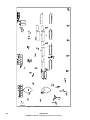
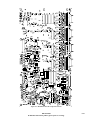
Note: Parts List for this board is covered in Section VII.
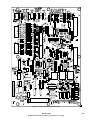
H.4 Location
H.2 Function
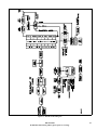
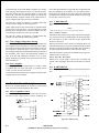
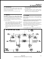
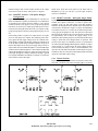
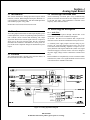
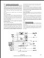
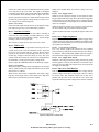
The Output Monitor board includes VSWR Detectors, VSWR
Self Test, ARC Detectors, Directional Coupler, Modulation
Monitor Sample Equalization circuits, Audio Detector, Airflow
Monitoring, and Supply Fault circuits.
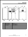
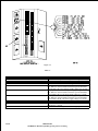
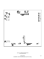
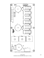
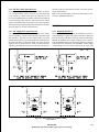
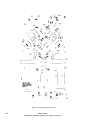
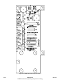
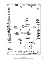
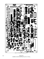
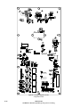
The Output Monitor board is located in the left side of the Left
PA compartment. (SEE VIEW 14)
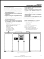
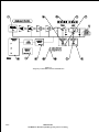
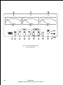
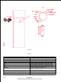
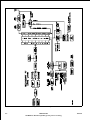
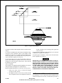
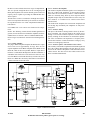
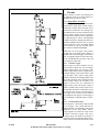
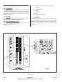
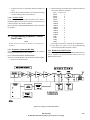
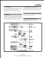
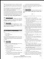
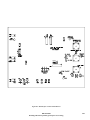
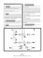
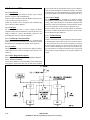
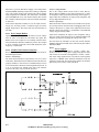
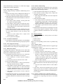
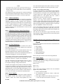
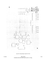
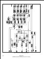
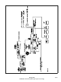
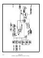
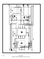
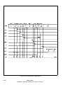
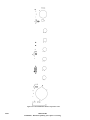
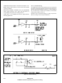
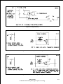
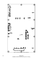
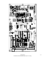
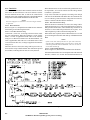
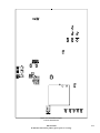
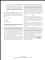
Figure H-1. Output Monitor Block Diagram
02/17/04
888-2339-002
WARNING: Disconnect primary power prior to servicing.
H-1