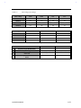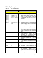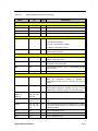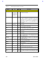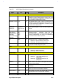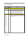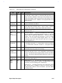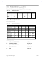
1
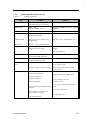
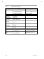
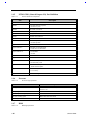
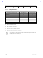
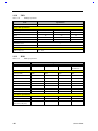
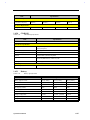
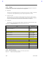
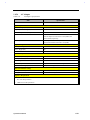
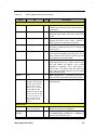
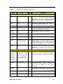
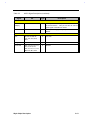
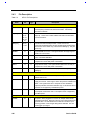
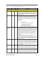
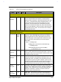
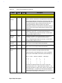
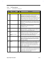
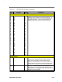
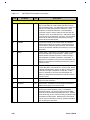
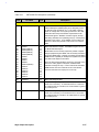
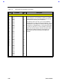
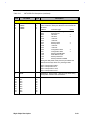
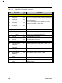
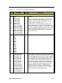
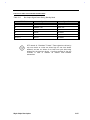
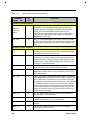
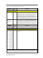
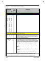
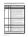
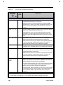
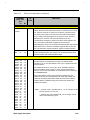
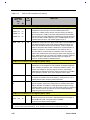
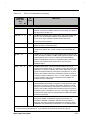
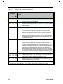
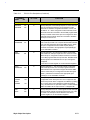
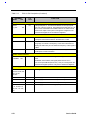
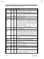
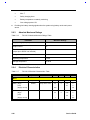
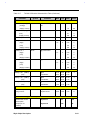
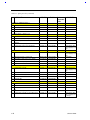
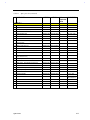
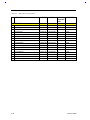
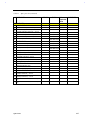
Table 2-4
Name
M7101 Pin Descriptions (Continued)
No.
Type
Description
PMU Input event interface : (11)
PS2
50
I
External PS2 MOUSE. This signal represents whether the PS2
MOUSE is plugged in or not. When a PS2 MOUSE is plugged in, a
high to low transition will generate a SMIJ. When a PS2 MOUSE is
pulled out, a low to high transition will generate a SMIJ as well. In
addition, the signal status can be read from BEEPER offset 0CBh
D1 register. Debounce circuit is built in. It detects both rising and
falling edges. This is a Smith-trigger input signal.
CRT
51
I
External CRT connector. This signal represents whether the
External CRT connector is plugged in or not. When an external
CRT connector is plugged in, a high to low transition will generate
an SMIJ. When an external CRT connector is pulled out, a low to
high transition will generate an SMIJ, too. Moreover, the signal
status can be read from BEEPER offset 0CBh D0 register.
Debounce circuit is built in. It detects both rising and falling edges.
Smith-trigger input.
HOTKEYJ
44
I
HotKey press. When HotKey is pressed, a high to low transition will
generate an SMIJ. Debounce circuit is built in. It detects only
falling edge. This is a Smith-trigger input signal.
FPVEE
56
I
LCD backlight VEE. LCD backlight VEE on/off control signal.
Internal circuit uses this signal to generate DISPLAY and CCFT
signals. On one hand, if FPVEE goes from low to high, DISPLAY
will go high after 62.5ms to 125ms. If FPVEE goes low, DISPLAY
will go low immediately. On the other hand, FPVEE will AND with
offset 0D2h D0 to generate CCFT. That is, if both FPVEE and offset
0D2h D0 are high then CCFT will be high or 1Khz clock with
programmable duty cycle. Otherwise CCFT will be low.
PMU output interface (9)
SLED
53
O
Square LED display. 1Hz/2Hz square wave output. It can drive the
LED to Flash. When disabled, this signal will be kept at high/low
level as programmed.
SPKCTL
55
O
Speaker output. This signal is connected to speaker circuit to
generate sound directly.
SQWO
54
O
Square wave output. Square wave output with 1Hz or 2Hz. When
disabled, this signal will keep at high/low level as programmed.
61-60
I/O
Programmable output control. These two pins are programmable
output control pins at different state. When Power on, these two
pins will be inputs and the Pull high( internal chip default is pull high
50K) or pull low (The pull low should use 4.7K resistor), will latch to
ON state register. The values of ON, DOZE and SLEEP registers
corresponding to four operation status can be programmed. That is,
when system is at different states, the corresponding register value
will be sent to SEL[1:0].
SEL[1:0]
2-28
Service Guide