1
5K-LE
Owners Manual
WARNING
WARNING: HIGH VOLTAGES ARE PRESENT BEHIND THE COVERS AND IN THE PAN ASSEMBLY.
Never remove the pan access cover assembly or rear cover assembly since there are no user serviceable parts
inside. The electrical and/or sensitive parts may only be serviced by an authorized Service Representative.
Important Safeguards :Read all instructions before attempting to operate this equipment.
To reduce the risk of fire and/or electric shock, do not attempt to disassemble this machine.
The machine is not intended for use in hazardous locations. Do not use in environments known to
contain flammable or explosive gases.
To prevent overheating, do not cover vent openings or use the machine over a radiator or heat register.
To reduce the risk of injury, refer all non-operator service functions to qualified service personnel.
Access only those operator designated areas of machine for jam clearing. All other areas of machine
requiring disassembly or removal of covers should only be accessed by qualified service personnel.
This machine cabinet serves to enclose hazardous parts. If the machine has been dropped or otherwise
had the cabinet stressed in any way, report it to your local service representative.
In the performance of operator service procedures, be certain the machine is unplugged from the wall.
Do not attempt to use this product in an unauthorized manner. To do so may expose you to mechanical
and / or electrical hazards.
Do not expose power cord to sharp points or edges.
To protect against shock, the power cord must only be plugged into a grounded receptacle. The ground
pin on the plug must never be removed.
The power cord should be routed so it cannot be walked upon.
Do not operate this machine with a damaged power cord or plug.
Unplug or otherwise disable this machine before cleaning.
Know how to turn off power in the work area, and to summon help in the event of an emergency.
Do not remove safety covers for cleaning, adjustments or repairs. Call your service representative.
Keep office supplies such as paper clips, staples, rubber bands, etc., away from machine.
Keep loose clothing ties, jewelry, and long hair away from moving parts of this machine.
Ink formulations for use in this machine are critical. Use only those specified.
Notice: Changes or modifications to this unit not expressly approved by the party responsible for
compliance could void the user’s authority to operate the equipment.
Treat every circuit as if it were live. Check first with a neon tester or a voltmeter.
Federal Communications Commission Compliance
"This device complies with Part 15 of the FCC Rules. Operation is subject to the following two conditions:
1).
2).
This device may not cause harmful interference, and
This device must accept any interference received, including interference that may cause
undesired operation.
NOTE:
This equipment has been tested and found to comply with FCC Rules Part 15 subpart B Class B for a digital
device. These limits are designed to provide reasonable protection against harmful interference in a residential installation. This
equipment generates, uses, and can radiate radio frequency energy and, if not installed and used in accordance with the
instructions, may cause harmful interference to radio communications. If this equipment does cause harmful interference to radio
or television reception, which can be determined by turning the equipment off and on, the user is encouraged to try to correct the
interference by one or more of the following measures: Reorient or relocate the receiving antenna.
- Increase the separation between the equipment and receiver.
- Connect the equipment into an outlet on a circuit different from that to which the receiver is connected.
- Consult the dealer or an experienced radio / TV technician for help.
Shielded cables must be used with this unit to ensure compliance with the Class B FCC limits.
Canadian DOC Compliance.
"This Class B digital apparatus meets all requirements of the Canadian Interference-Causing Equipment Regulations.
Cet appareil numérique de la classe B respecte toutes les exigences du Règlement sur le matériel brouilleur du
Canada.
Caution
Danger of explosion if battery is incorrectly replaced. Replace only with the same or equivalent type recommended by the
manufacturer. Dispose of used batteries according to the manufacturer’s instructions.
VORSICHT
Explosionsgefahr bei unsachgemäßem Austausch der Batterie.
Ersatz nur durch denselben oder einen vom
Hersteller empfohlenen gleichwertigen Typ.
Entsorgung gebrauchter Batterien nach
Angaben des Herstellers.
ADVARSEL
Lithiumbatteri − Eksplosionsfare ved fejlagtig håndtering.
Udskiftning må kun ske med batteri af samme fabrikat og type.
Levér det brugte batteri tilbage tilleverandøren.
Notice
The information in this document is subject to change without notice. Bryce Office Systems makes no warranty of
any kind with regard to the material contained herein. Bryce Office Systems will not be liable for incidental or
consequential damages in connection with the furnishing, performance or use of this material.
TABLE OF CONTENTS
FOREWORD
INTRODUCTION
UNPACKING
Chapter 1
Unpacking the Printer ....................................................................................1 - 1
PARTS OF THE PRINTER
Chapter 2
Printer Parts & Locations...............................................................................2 - 1
SETTING UP THE PRINTER
Chapter 3
Choosing a Good Location for the Printer.........................................3 - 1
Removing Protective Materials .........................................................3 - 1
Installing the Wire Form Assembly...................................................3 - 2
Installing the Sliding Fence ...............................................................3 - 3
Connecting to the Computer ..............................................................3 - 4
Connecting the Power Cord ...............................................................3 - 5
TRYING OUT THE PRINTER
Chapter 4
Power On .......................................................................................................4 - 1
Installing a Ink Jet Cartridge..............................................................4 - 1
Removing a Ink Jet Cartridge. ...........................................................4 - 3
Preparing the Media...........................................................................4 - 4
Media Types ......................................................................................4 - 5
Setting the Proper Feed Gap ..............................................................4 - 6
Setup with #10 Envelopes..................................................................4 - 7
Wire Form Adjustments ....................................................................4 - 7
Wire Form Center Adjustment...........................................................4 - 8
Wire Form Height Adjustment ..........................................................4 - 9
Setting the Feed Ramp .......................................................................4 - 9
Setting the Sliding Fence ...................................................................4 - 10
Fine Tuning the Adjustment Lever ....................................................4 - 11
Adjustment of the Left Hand & Right Hand Slider Assembly ..........4 - 12
Output Stack Height...........................................................................4 - 13
Factors that Affect the Printers Performance.....................................4 - 13
CLEANING AND MAINTAINING THE PRINTER
Chapter 5
PREVENTATIVE MAINTENANCE FOR THE PRINTER ........................5 - 1
Cleaning the Feed Rollers..................................................................5 - 1
Cleaning the Ink Jet Cartridge ...........................................................5 - 1
Cleaning the Sensor Assembly ..........................................................5 - 2
Revision A
5K-LE OWNERS MANUAL
P/N 90-00852-001
Section i - 1
TABLE OF CONTENTS
Cleaning the Right & Left Hand Slider Rollers.................................5 - 2
Cleaning the Floor and Covers ..........................................................5 - 2
PRINTER MENU SYSTEM
Chapter 6
FRONT PANEL CONTROLS AND LCD DISPLAY ..................................6 - 1
What does the display show...............................................................6 - 2
MAIN MENU ................................................................................................6 - 3
• 1. Address Layout .......................................................................6 - 3
• 2. Print Quality............................................................................6 - 5
• 3. Font .........................................................................................6 - 5
• 4. Barcode ...................................................................................6 - 6
• 5. Address Recovery ...................................................................6 - 7
• 6. Clear Counter ..........................................................................6 - 7
• 7. Job Settings .............................................................................6 - 8
SETUP MENU...............................................................................................6 - 9
• 1. Heavy Media Mode ................................................................6 - 9
• 2. Test Print Head .......................................................................6 - 9
• 3. Purge Print Head .....................................................................6 - 10
• 4. Lines Per Address ...................................................................6 - 10
• 5. Communications .....................................................................6 - 10
• 6. Hex Dump Mode.....................................................................6 - 11
• 7. Language.................................................................................6 - 11
• 8. Env. Feed Delay......................................................................6 - 12
• 9. Env. Auto Eject.......................................................................6 - 12
• 10. Rom Revision#.......................................................................6 - 13
SERVICE MENU ..........................................................................................6 - 14
• 1. Left Justify ..............................................................................6 - 14
• 2. Test Paper Sensor....................................................................6 - 15
• 3. Test Shuttle Motor ..................................................................6 - 15
• 4. Test Paper Motor ....................................................................6 - 16
• 5. Test Display ............................................................................6 - 16
• 6. Env. Bottom Edge...................................................................6 - 16
• Resetting the Printer.....................................................................6 - 17
TROUBLESHOOTING & DIAGNOSTICS
Chapter 7
SYMPTOMS & SOLUTIONS ..........................................................7 - 1
Revision A
5K-LE OWNERS MANUAL
P/N 90-00852-001
Section i - 2
TABLE OF CONTENTS
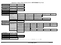
PRINTER MENUS
APPENDIX A
5K-LE MAIN MENU ....................................................................................A - 1
5K-LE SETUP MENU ..................................................................................A - 3
5K-LE SERVICE MENU ..............................................................................A - 5
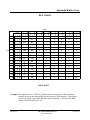
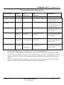
HEX CHART
APPENDIX B
HEX CHART.................................................................................................B - 1
PRINTER CONTROL COMMANDS
APPENDIX C
PCL COMMAND CODES............................................................................C - 1
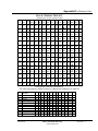
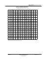
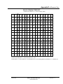
CHARACTER SET
APPENDIX D
5K-LE CHARACTER SET ..........................................................................D - 1
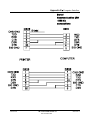
COMPUTER INTERFACE WIRING DIAGRAM
APPENDIX E
RS 232 SERIAL CABLE WIRING DIAGRAM...........................................E - 1
CENTRONICS CABLE ................................................................................E - 2
PRINTING WITH SOFTWARE
APPENDIX F
SOFTWARE TABLE OF CONTENTS ........................................................F - 1
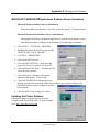
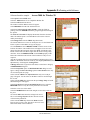
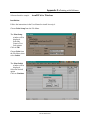
SOFTWARE SETUP.....................................................................................F - 2
TECHNICAL SPECIFICATIONS
APPENDIX G
US MAIL REQUIREMENTS
APPENDIX H
DELIVERY POINT BARCODE...................................................................H - 1
PLANET CODE BARCODE ........................................................................H - 2
CODE 39 BARCODE....................................................................................H - 2
GLOSSARY
APPENDIX I
ORDERING INFORMATION
APPENDIX J
OPTIONS & SUPPLIES................................................................................J - 1
Revision A
5K-LE OWNERS MANUAL
P/N 90-00852-001
Section i - 3
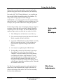
Introduction
This manual is for the person who is new to the Bryce 5K-LE
Address Printer and needs step by step instructions to setup and
operate the printer.
Who is this
manual for?
The appendix at the end of the manual has information for those
who are familiar with the 5K-LE printer and simply want a quick
reference or want more specific technical information on the 5K-LE
printer.
Section 1 - Unpacking
A list of the components that came with your new printer.
Section 2 – Parts of the Printer
Introduces you to the printer and where components are found.
Section 3 – Setting up the Printer
Describes the basics of how to setup and install the components of
the printer for the first time.
Section 4 – Trying out the Printer
Step by step instructions to operate the address printer and some
adjustments to maximize the performance of the printer.
Section 5 – Cleaning and Maintaining the Printer
General maintenance steps to keep the printer clean and functioning
properly.
Section 6 – Printer Menu System
Explains each of the menu options of the address printer.
Section 7- Troubleshooting and Diagnostics
A list of possible problems you may encounter when operating the
printer and their solutions.
Appendices
The appendices include a quick reference table for the 5K-LE
menus, a listing of the PCL commands the printer recognizes, a hex
chart to help work through a HEX dump, and references of setting
up the most popular software to work with the printer. The final
section has a list of supplies available for your printer.
Revision A
5K-LE OWNERS MANUAL
P/N 90-00852-001
1
Unpacking
Unpacking the Printer
•
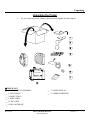
As you remove the boxes contents, check the pieces against the following list.
;CHECK LIST
__ 1. PAPER CATCH ASSEMBLY
__ 2. LONG FENCE
__ 3. SHORT FENCE
__ 4. WIRE FORM
__ 5. LINE CORD
__ 6. INK CARTRIDGE
Revision A
__ 7. USERS MANUAL
__ 8. ADDRESS PRINTER
5K-LE OWNERS MANUAL
P/N 90-00852-001
Section 1 - 1
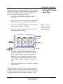
Parts of the Printer
Printer Parts and Locations
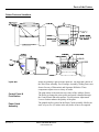
Input Bin
Control Panel &
Print Station
Paper Catch
Assembly
Revision A
Media for printing is placed in the input bin. The input bin consists of
the Wire Form assembly, Feed Carriage Assembly, Sliding Fence (not
shown for ease of illustration) and Separator H-Blocks. These
components adjust to run a variety of media.
The print station is the main nervous center of the Address Printer.
The ability to change the print quality and speed is handled through
the Control Panel and menu options. Use the printers Adjustment
Lever to further enhance the quality of the print.
The printed media is placed in the Paper Catch Assembly. Media can
stack of up to five (5) inches in the tray before it has to be emptied.
5K-LE OWNERS MANUAL
P/N 90-00852-001
Section 2 - 1
Setting up the Printer
The following environmental considerations must be kept in
mind when selecting a location for the Address Printer. Doing
otherwise may affect the operation and performance of the
Address Printer.
1. Place the printer close enough to the computer for the
parallel or serial cable to reach.
2. Place the printer on a flat, stable surface.
3. Use a grounded, dedicated outlet for the printer only.
Note: Do not use an adapter plug.
Choosing a
Good Location
for the Printer
Note: AB switches are
not recommended for
operation with this
printer.
4. Avoid locations near direct sunlight, excessive heat,
high humidity, moisture, or dust.
5. Keep the entire system away from large motors or
other appliances that might disturb the power supply or
create potential interference.
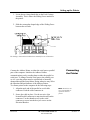
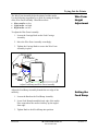
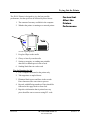
The printer is protected during shipping by a sheet of
corrugated cardboard around the Print Head Holder Assembly.
1. Raise the Front Door to gain access to the interior.
Removing
Protective
Materials
2. Remove the corrugated cardboard. Be careful not to
grab or pull on the ribbon in the back of the Print Head
Holder Assembly.
Revision A
5K-LE OWNERS MANUAL
P/N 90-00852-001
Section 3 - 1
Setting up the Printer
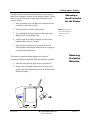
1. Turn the Carriage Knob counter-clockwise on the Feed
Carriage Assembly until the end of the Carriage Knob
is no longer visible in the slot for the supporting bar of
the Wire Form Assembly.
Installation of
the Wire Form
Assembly
Turn Carriage Knob on the Feed Carriage Assembly to clear the way for the Wire Form Assembly
support bar.
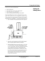
1. Move the Feed Ramp to the center of the Wire Form.
Turn the Carriage Knob to secure in place.
Position the Feed Ramp to the center of the Wire Form Assembly and fasten in place.
Revision A
5K-LE OWNERS MANUAL
P/N 90-00852-001
Section 3 - 2
Setting up the Printer
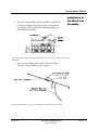
2. Raise the Wire Form to a vertical position.
3. Press Wire Form underneath the two tabs.
Front Support Plate is not shown for ease of illustration.
4. Rotate top of Wire Form down and insert the curved
supporting bar through the slot in the Feed Carriage
Assembly. Slight force on the Support Bar may be
needed to fit it into the slot.
5. Turn the Carriage Knob on the Feed Carriage
Assembly to hold the Wire Form Assembly in place.
Included in the Accessory Kit is a long and short Sliding
Fence. The fences keep the media together in a stack. Use the
short Sliding Fence for postcards up to media the size of #10
envelopes. Use the Long Sliding Fence for all other sizes.
Revision A
5K-LE OWNERS MANUAL
P/N 90-00852-001
Installing the
Sliding Fence
Section 3 - 3
Setting up the Printer
1. Locate the two long slotted tabs on the Feed Carriage
Assembly. This is where the Sliding Fence attaches to
the printer.
2. Slide the rectangular shaped edge of the Sliding Fence
between the two tabs.
The drawing is shown without the Wire Form Assembly for ease of illustration.
Connect the Address Printer to either the serial port or parallel
port of the computer. Initialize the Address Printers
communications port by sending data to either the parallel or
serial port. To change from the serial port to the parallel port
or vice versa the printer must be reinitialized or manually
changed through the Setup Menu. Doing otherwise may affect
the operation and performance of the Address Printer.
To connect printer to the computer do the following steps.
1. Align the male end of the parallel or serial cable
connector. Push the cable connector in.
2. Secure the cable in place. Use the two wire clips
located Parallel connector to snap into the tabs on the
connector. Use the thumb screws on the serial
connector to screw into the hex jack screws on the
Electrical Bracket.
Revision A
5K-LE OWNERS MANUAL
P/N 90-00852-001
Connecting
the Printer
Note: AB switches are
not recommended for
operation with this
printer.
Section 3 - 4
Setting up the Printer
3. Align the other end of the cable to the connector on the
computer and push into the port.
4. Secure the cable in place. Use the thumb screws on the
connector to screw into the hex jack screws on the
computer.
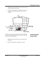
The power cord receptacle is located on the Electrical Bracket
Assembly along with the ON/OFF power switch. Connect the
power cord to a grounded outlet.
Connecting the
Power Cord
1. Push the female end of the power cord into the power
receptacle.
2. Plug the other end into a grounded power outlet.
Revision A
5K-LE OWNERS MANUAL
P/N 90-00852-001
Section 3 - 5
Trying Out the Printer
The power cord is plugged in, the printer is connected to the
computer. Now you can turn the power on.
Power On
• Press on the printers' ON/OFF power switch.
The switch is located on the rear of the printer
next to the line cord receptacle. Press on the
symbol "I" (ON) position. The printer LCD
menu will display PRINTER INITIALIZING
and then automatically go ON LINE.
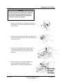
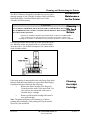
The Address Printer uses an Ink Jet Cartridge for printing.
You must install the Ink Jet Cartridge before you use the
machine. To install the cartridge do the following:
• Verify the LCD display message on the top line of the
Installing an Ink
Jet Cartridge
display is either OFF LINE or ON LINE.
• Open the front cover.
• On the top Control Panel, depress the Cartridge button
([+] plus button) and the carriage will travel to the
center position and stop. DO NOT MOVE THE
CARRIAGE BY HAND!! Damage may occur to the
carriage.
Revision A
5K-LE OWNERS MANUAL
P/N 90-00852-001
Section 4 - 1
Trying Out the Printer
Caution!
The ink in the print cartridge may be harmful
if swallowed. Keep new and used cartridges
out of reach of children. Discard empty print
cartridges in the proper manner.
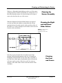
1. Remove Cartridge from the shipping container by
peeling top cover off. Be careful not to touch the
copper ribbon.
2. Gently remove both pieces of tape covering the ink
nozzles on the print cartridge. Be careful not to touch
the copper nozzles.
3. Gently insert cartridge down at approximately a
45 degree angle into the cradle with the blue
arrow on the cartridge top pointing toward the
input bin.
4. Place forefinger on cradle tab and thumb on
top of ink cartridge and gently squeeze
together until the cartridge snaps into place.
Removing
an Inkjet
Cartridge
Revision A
5K-LE OWNERS MANUAL
P/N 90-00852-001
Section 4 - 2
Trying Out the Printer
1. Grasp the blue cartridge top while placing your thumb
on the cartridge cradle. Pull the cartridge top toward
you until the cartridge "pops" loose.
2. Lift the print cartridge out of the cradle.
Revision A
5K-LE OWNERS MANUAL
P/N 90-00852-001
Section 4 - 3
Trying Out the Printer
Recheck that all the necessary components of the printer are
installed.
• Is the Wire Form Assembly installed?
• Is the Sliding Fence installed?
• Is the printer plugged into a power outlet?
• Does the printer have an Ink Jet Cartridge installed?
• Is the printer connected to the computer?
Preparing the Media
Now that all the parts of the printer are installed the printer
needs to be adjusted to work with the media. To avoid
problems of misfeeding and jams the media must also be made
ready for the printer.
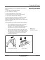
Use the following steps to make the media ready for printing:
1. Take a manageable pile of media and while holding
them (as shown in the following illustration as
reference A), "fan" all sides of the media to make sure
that each piece of media is free from one another.
2. Square the pile against the table top, assuring a square
pile on all sides. (Reference B in following illustration)
This will also allow media to settle toward the bottom
of a stuffed envelope and will increase the feeding
capabilities of the printer.
Fan All Sides of Media
Revision A
Note: Maximum
thickness is 1/16”
(1.587mm) for the 5K-LE.
Square Media
5K-LE OWNERS MANUAL
P/N 90-00852-001
Section 4 - 4
Trying Out the Printer
The printer is designed to feed and print on a variety of media
with various finishes and coatings. The sharpness of the print
quality will vary with different media types, depending on
how absorbent the media is, as well as other qualities. The
best results can be achieved using white wove bonded stock.
The printing quality will be less sharp on tyvek, recycled and
glossy media.
The types of media the printer is able to use is:
Media Types
•
Envelopes: should be stacked to feed with the
bottom edge first (non flap edge).
• Booklets: should be stacked with the sealed edge
leading or stacked with the sealed edge placed
parallel to the rear wall of the Rear Support Plate
Assembly.
• Catalogs: should be stacked with the sealed edge
leading or stacked with the sealed edge placed
parallel to the rear wall of the Rear Support Plate
Assembly.
• Postcards: must be 3.5” x 5” or larger.
• Self Mailers: may be folded in half or “C” or “Z”.
The media must be tabbed and not exceed the
maximum allowable thickness.
• Paper: may consist of 16 to 80lb of uncoated to
coated stock. The maximum width and height is
specified in Appendix G.
All folded material and catalogs must be tabbed as per postal
regulations.
The paper types that can be used are:
•
•
•
•
•
•
•
Revision A
White wove
Bond Paper
Recycled Paper
Coated Paper
Card Stock
Brown Kraft
Manila
5K-LE OWNERS MANUAL
P/N 90-00852-001
Section 4 - 5
Trying Out the Printer
To start a print job the feed gap should be set for each type of
media used in the printer. The feed gap is the spacing between
the feed rollers and the separators. Set the feed gap with a
piece media by following these procedures:
1. Loosen the H Block Knob on the three H-Block
Assemblies.
Setting the Proper
Feed Gap
2. Raise the three H-Block Assemblies up. Tighten the H
Block Knobs to secure H-Block Assemblies in place.
3. Take a piece of the media and place between the Feed
Rollers and the H-Block Assemblies.
4. Square the edge of the media against the wall of the
Rear Support Plate Assembly.
Hint: set a smaller gap
between the separators
and feed roller, by using
standard copy paper
when using post cards.
5. Loosen the H Block Knobs and allow the H-Block
Assemblies to drop on top of the media. Keep the HBlock Assembles up that won’t contact the media.
When just one of the separator fingers is in contact
with the media use another piece beneath the other
separator finger and the Feed Roller to set the feed
gap.
6. Tighten H Block Knobs to secure H-Block Assemblies
in this position.
When the feed gap is not set correctly the printer will have
feeding problems. When the gap is too wide double feeding
(feeding two or more pieces at a time) will occur. If the gap is
to small the media will jam beneath the separators. If you
Revision A
5K-LE OWNERS MANUAL
P/N 90-00852-001
Section 4 - 6
Trying Out the Printer
followed the preceding steps and are experiencing feeding
problem using post cards or stuffed media try the following:
Post cards (.003" [0.0762 mm] thickness) - set a smaller gap
between the H-Block Assemblies and the Feed Rollers. Try
using a sheet of copy paper to set the feed gap.
Stuffed Media - set a larger gap between the separator blocks
and the feed roller. Try adding two or three, number ten (# 10)
envelopes, on top of the media before setting the separators.
Perform the preceding steps for setting the feed gap using #10
envelopes. Notice that only two of the H-Block Assemblies
completely rest on the envelope. The third H-Block has one
separator finger on the envelope and one on the feed roller.
Setup with
#10
Envelopes
1. Take Sliding Fence off and remove out of the way.
2. Fit a second envelope between the other half of the HBlock Assembly and the Feed Roller.
3. Loosen the H Block Knob to let the H-Block Assembly
fall freely onto the envelope. Verify envelopes are
between all the Separators Fingers and the Feed
Rollers.
4. Lock in place by tightening the H Block Knob.
5. The Input Bin can now be filled with #10 envelopes
for printing. The stack of envelopes should be
"shingled" or layered with the piece on top partially
covering the piece below it like shingles on a roof.
Load into the input bin with flap away from the feed
roller and facing downward. Start with just a few
envelopes to start the stack and get the angled contour
of the bin area, then add several more pieces. Then add
the remainder of the stack.
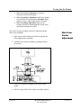
The Wire Form assembly supports the media stacked in the
input bin area and redistributes the weight of the media to
assist in the feeding of the media. The Wire Form assembly
has three basic adjustments.
Revision A
5K-LE OWNERS MANUAL
P/N 90-00852-001
Wire Form
Adjustments
Section 4 - 7
Trying Out the Printer
•
•
•
Wire Form Center Adjustment to eliminate
skewing of the media and print.
Wire Form Height Adjustment to allow the printer
to feed media of varying density. Example: Rigid
media is set low, light weight media is set high.
Wire Form Ramp Adjustment improves the
feeding of media by distributing the weight of the
media stack onto the feed roller.
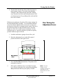
The Feed Carriage Assembly needs to be adjusted with the
Wire Form Assembly.
1. Place a piece of the media in the bin area against the
Rear Support Plate Assembly.
Wire Form
Center
Adjustment
2. Unlock Feed Carriage assembly by pushing locking
lever down
Adjust Feed Carriage
3. Slide Feed Carriage Assembly to the center of the
media.
4. Pull lever up to lock Feed Carriage Assembly in place.
Revision A
5K-LE OWNERS MANUAL
P/N 90-00852-001
Section 4 - 8
Trying Out the Printer
The Wire Form Assembly helps the printer feed the media.
Use the following suggestions as a guide for setting the height
of the Wire Form Assembly. When the media is:
• Heavy media- set low
• Light media - set high.
• Rigid media - set low
Wire Form
Height
Adjustment
To adjust the Wire Form Assembly:
1. Loosen the Carriage Knob on the Feed Carriage
Assembly.
2. Move the Wire Form Assembly accordingly.
3. Tighten the Carriage Knob to secure the Wire Form
Assembly in place.
Adjust Feed Ramp and Wire Form Assembly
Adjust the Feed Ramp Assembly beneath the rear edge of the
media by:
1. Loosen the Knob on the Feed Ramp Assembly.
Setting the
Feed Ramp
2. Lower Feed Ramp beneath the back edge of the media.
Place ramp where the media is halfway up the angled
front edge.
3. Tighten Knob to lock Feed Ramp into position.
Revision A
5K-LE OWNERS MANUAL
P/N 90-00852-001
Section 4 - 9
Trying Out the Printer
Recheck your setup and adjustments:
•
•
•
•
Is the feed gap set?
Is the Wire Form in the center of the media?
Is the Wire Form at a good height?
Is the Feed Ramp beneath the edge of the media?
Setting the
Sliding Fence
Position the Sliding Fence before stacking the bin area with
media. The fence has to be close enough to the media to keep
it from going in at an angle and loose enough for the media to
drop down to the Feed Rollers. To properly position the fence:
1. Place a handful of the prepared media in the input bin
area.
2. Square the stack against the wall of the Rear Support
Plate Assembly and the H-Block Assemblies.
3. Push the Sliding Fence in near the media. Leave a gap
of 1/16 of a inch [1.587 mm] or the thickness of one
or two #10 envelopes. This size of gap places the fence
close enough to prevent pieces from twisting and
turning as they enter the printer, and the fence won’t
be to close to the media to trap and restrain the pieces
between the fence and the wall of the Rear Support
Plate Assembly. This would hinder the media from
being fed into the printer.
Revision A
5K-LE OWNERS MANUAL
P/N 90-00852-001
Section 4 - 10
Trying Out the Printer
4. Put the media into the bin. Start with a few pieces to
get the proper contour. The media stack should be
"shingled" when loaded into the input bin with flap
away from the feed roller and facing downward. Add
several more pieces. Keep adding to the stack until the
bin is full of media.
Different sizes and types of media call for unique settings for
the Print Head Holder Assembly. To accommodate different
sizes of media the Adjustment Lever increases or decreases
the distance of the ink jet cartridge from the media. This gives
the printer the ability to adapt to different types of media.
Proper use of the lever results in clean crisp print. Use the
following steps as a general guideline to get the best quality
possible with most types of media:
Fine Tuning the
Adjustment Lever
1. Load the media that is going to be used for a job.
2. Raise the Adjustment Lever to the fully opened
position. Reference the Figure below.
3. Press the [Test Env.] button down. The printer feeds
and prints a test piece.
4.
If the print is indistinct, hazy or too light, lower the
lever. Keep lowering the lever and pressing the [Test
Env.] button until the best print quality is found.
Revision A
5K-LE OWNERS MANUAL
P/N 90-00852-001
Note: If the print
smudges the ink
cartridge is touching the
media. Raise up the
Adjustment Lever until
it stops.
Section 4 - 11
Trying Out the Printer
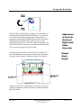
Push the Slider Assembly left or right to move the slider to a
new position on the shaft. Place the Sliders to 1/4 of an inch
(6.35 mm) from the left and right edges of the media. It is
important to check that the Sliders do not contact any printed
information on the media. If the rollers do roll over any
printed areas they will act as a brush with paint and smear the
print. Move the rollers in more or out more toward the nearest
clear zone (non printing area of the media).
The Paper Catch Assembly will stack up to five inches (12.7
cm) of media before it is necessary to remove the stack from
the paper catch assembly. If the paper catch is not emptied
Adjustment
of the Left
Hand and
Right Hand
Slider
Assembly
Output
Stack
Height
regularly then there is the potential for the stack to be out of
sequence, particularly when the printer is printing toward the
top of the media.
Revision A
5K-LE OWNERS MANUAL
P/N 90-00852-001
Section 4 - 12
Trying Out the Printer
The 5K-LE Printer is designed to give the best possible
performance, but the speed can be affected by these factors.
1. The amount of memory available in the computer.
2. Whether the printer is running as a network printer
Factors that
Affect the
Printers
Performance
or with a print spooler.
3. Pre-glued flaps on the media
4. Glossy or heavily waxed media.
5. Setting up margins, or sending non printable
characters or blank spaces in the records.
6. Sending blank lines in each record.
Tips for Running the Job
1. Use a computer dedicated to the printer only.
2. Tab magazines or stapled sheets.
3. Eliminate blank spaces and lines in the records.
Extra characters take extra time to process.
4. Records with differing numbers of lines should be
followed with a page break or form feed.
5. Repetitive information that is printed on every
piece should be sent as a macro using PCL code.
Revision A
5K-LE OWNERS MANUAL
P/N 90-00852-001
Section 4 - 13
Cleaning and Maintaining the Printer
The 5K-LE Printer is designed for trouble free service with a
minimal amount of care. Periodic cleaning of the Feed Rollers,
Right Hand Slider, Left Hand Slider and Lower Guide
Assembly will be necessary.
Preventative
Maintenance
for the Printer
Cleaning
CLEAN PRINT CARTRIDGE, INK SURFACES AND COVERS WITH PLAIN WATER.
the Feed
ALL RUBBER ROLLERS CAN BE CLEANED WITH ISOPROPYL, DENATURED & RUBBING
Rollers
ALCOHOL OR WATER ONLY.
CAUTION!!
USING ANY OTHER CLEANING SOLVENTS WILL VOID ALL WARRANTIES.
Keep cleaning solvents with petroleum based products from rubber or plastic parts.
Anything but ALCOHOL or WATER will cause premature breakdown of rubber compound.
Lint and paper dust tends to build up on the feed rollers with
use. When the rollers are glazed or have a yellowish residue,
clean the rollers. Use alcohol to dampen a soft cotton cloth to
clean all rubber rollers.
If the print quality is unacceptable select the Purge Print Head
function from the Setup Menu (see section Print Head Purge).
If problems still persist then do the following:
•
Remove the Print Cartridge (See chapter 4).
Clean the nozzles with a soft cotton cloth. Use
a dry cloth or one moistened with water to
clean the ink jet cartridge.
•
Remove problem print cartridge and install a
new print cartridge.
Note: The printer performs a self cleaning cycle before
printing and periodically while printing to keep the nozzles
clear of dry ink and debris.
Revision A
5K-LE OWNERS MANUAL
P/N 90-00852-001
Cleaning
the Inkjet
Cartridge
Section 5 - 1
Cleaning and Maintaining the Printer
With use, a film and/or dust builds up on the eye of the sensor
causing misfeeds of media. Periodically use compressed air to
blow dust from the sensors. For caked on dust use a Q-tip to
remove the dust from the eye of the sensor.
Cleaning the
Sensor Assembly
When the Right and Left Hand Slider Rollers are adjusted
over the area where the address is printed the ink will get
transferred from the media onto the rollers and the surface of
the sliders. Use water to dampen a soft cloth to remove the ink
from the rollers and sliders.
Cleaning the Right
and Left Hand
Slider Rollers
Note: The lower half of
the Sensor is seen
through the hole in the
floor.
Ink will get sprayed on the Floor Assembly from all the
purging, setting up and printing records, etc. Eventually an
enough ink will accumulate on top of the Floor Assembly to
give the floor a black glossy sheen and the back of the media
will start to pick up some of the ink as well. Use water to
dampen a soft cotton cloth to remove the ink from the Floor
Assembly.
Revision A
5K-LE OWNERS MANUAL
P/N 90-00852-001
Cleaning
the Floor
and Covers
Section 5 - 2
Printer Menu System
Front Panel Controls and LCD Display
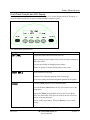
Use the controls on the Front Panel Assembly, consisting of six control buttons and an LCD display, to
set up the Addressing Printer for proper operation with the computer system.
The control button definitions are:
Button
Function
[ON LINE]
Toggles the printer either On Line or Off Line.
Begins printing accepted address data (records) from the computer or
data in the buffer.
Exits the menus with out changing menu settings.
Allows the printer to resume printing after an error occurs.
[TEST ENV.]
Prints a internal test message.
Hold down for continuous printing of the test message.
Prints menu settings and internal alignment patterns for the printer.
[MENU]
Press the [Menu] button to access the Main Menu.
Press and hold the [Menu] button for two (2) seconds to access the
Setup Menu.
Depress the [Menu] and [-] buttons to access the Service Menu.
Note: The printer must feed a piece of media or an error will occur
instead of entering the menu.
Exit the control panel menus. First press [Enter] to save a menu
setting.
Revision A
5K-LE OWNERS MANUAL
P/N 90-00852-001
Section 6 - 1
Printer Menu System
[ENTER]
Selects a menu option displayed on the control panel.
Saves a new menu setting. An asterisk (*) will appear to the right of
the value to indicate the new value has been entered.
[+] / [-]
or
[CARTRIDGE] /
[EJECT]
Scroll up [+] and down [-] through the menu options.
Enters a YES [+] or NO [-] for particular menu options.
The [Cartridge] and [Eject] buttons will function when the printer
is either OFF LINE or ON LINE.
Press the [Cartridge] button and the printer will move the Print
Head Holder over to the center position for access to the Print Head
Holder to install and remove a print cartridge. Press the YES [+] or
NO [-] button to answer the display question, then the Print Head
Holder will return back to the park position.
Press the [Eject] button to feed a piece of media through the machine
or eject a piece of media from under the Exit Sliders.
What does the display show?
Conventions used in the Printer Menu System section.
Bold with brackets is used for the [Menu], [On Line], [Enter], [Test Env.], [Eject], [+] Plus, [-] Minus
buttons when they must be pressed to program or operate the printer.
Special fonts are used to highlight words that appear on the LCD display, and menu options: i.e. MAIN
MENU, SETUP MENU or SERVICE MENU. Italics are used to define the function of the printer menu
option.
Revision A
5K-LE OWNERS MANUAL
P/N 90-00852-001
Section 6 - 2
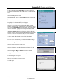
Printer Menu System
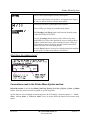
Main Menu
Use this menu to choose the format and style of address printed and for information to assist in
production. Selected menu options from a sub-menu will appear first in the list of options.
Note: The printer driver overrides most control panel settings in the printer. Some of the control
panel settings are also configured in the printer driver.
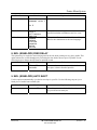
1. ADDRESS LAYOUT
Use this option to change the page layout for your mail piece.
Menu Items
Selections
Explanation
A. Distance To Right
0.00 to 9.40
This menu item allows you to change the position of
the record on the media by moving the record away
from the right edge of the media. Distance to Right
is the distance measured from the Right edge of the
media to the first printable character.
B. Distance To Bottom
0.00 to 15.00
This menu item allows you to change the position of
the record. The Distance To Bottom is the distance
between the bottom edge of the media and the base
of the first line of the address. Note: A Lower Right
Barcode will not print unless a bottom margin of 5/8
(1.58 cm) inches is retained.
C. Line Spacing
Automatic
3 lines /
4 lines /
6 lines /
8 lines /
This sets the distance between lines of text. It is
measured as the number of lines per inch of text.
Note: Whenever changing the point size of the font,
use the automatic line spacing option. The printer
will automatically select the correct setting for the
increased or decreased font size of the characters
being printed.
D. Orientation
inch
inch
inch
inch
This item changes the direction that the print
appears on the media.
Normal or
Invert
Normal prints upright when viewed from the front
of the Head Print Assemblies. The Lower Right
Barcode will only print in Normal orientation.
Invert reverses the print 180 degrees. Setting the
printer to Invert does change some of the menu
items.
E. Orientation Cntrl.
(Control)
Automatic or
Manual
This option allows the printer to ignore the
orientation commands sent by the computer.
Automatic When the Orientation Control is set to
Automatic the printer acknowledges the orientation
commands sent from the computer.
Revision A
5K-LE OWNERS MANUAL
P/N 90-00852-001
Section 6 - 3
Printer Menu System
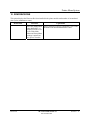
Menu Items
Selections
Explanation
Manual Setting the Orientation to Manual notifies
the printer to use the menu settings for orientation.
A. Distance To Left
0.00 to 9.40
This menu item only appears when the Orientation
is set to Invert. Distance From Right is identical to
Distance From Left except the distance is measured
from the Right edge of the media.
B. Distance To Bottom
0.00 to 15.00
This menu item only appears when the Orientation
is set to Invert. The Distance from Bottom is the
distance between the bottom edge of the media and
the base of the first line of the address.
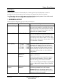
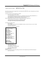
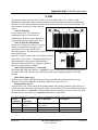
Example of using a
series of 3 ‘#’
characters in the
Horizontal Break
Marker setting to
pause the printer.
Example of using a
series of 3 ‘#’
characters in the
Vertical Break
Marker setting to
pause the printer.
Revision A
###
**************23
XYZ Corporation
123 Washington Road
Anytown, CT 06470-1234
**************23**
XYZ Corporation
#
#
123 Washington Road
#
Anytown, CT 06470-1234
5K-LE OWNERS MANUAL
P/N 90-00852-001
Section 6 - 4
Printer Menu System
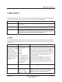
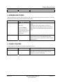
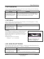
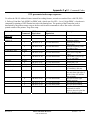
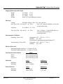
2. PRINT QUALITY
This option changes the speed of the printer and the density of the characters printed on the media. These
menu items are available in the printer driver and override the control panel settings.
Menu Items
Explanation
Executive
This is the darkest of the four print qualities, the slowest print speed and uses
the most ink.
Letter
Letter quality is used for documents that require a finished, polished
appearance. Use the following steps to change the quality of print to dark gray.
Draft
Draft quality prints documents the fastest and saves ink. This option offers the
highest print speed and prints the lightest of the three print qualities. Use the
following steps to change the quality of print to light gray.
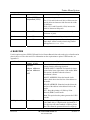
3. FONT
Use this option to alter the fonts characteristics: typeface, point size, spacing, stroke weight, and style.
The printer driver downloads Windows True Type fonts and overrides internal fonts selected through the
control panel.
Menu Items
Selections
Explanation
A. Name
Courier
Select the style of font to print the records with.
Note: When A. NAME
is shown on the
display as a Menu
option, press the [Test
Env.] button and a
complete listing of the
available fonts will be
printed out in their
typeface.
San Serif
Names of fonts that
are recognized from
the PCMCIA Card slot
will be added to the
end of the list of
selections.
Many optional fonts are available by installing an
optional font card. The Font card must be installed
(Font label facing the front of the printer). Turn the
printer power off for 10 seconds or more. Insert the
font card, then power on the printer to use the
external font card.
Note: Press the [Test Env.] button when a font
name is displayed on the LCD. A list of the
character set is printed in the fonts typeface. Use
these same steps to print a character set from a font
card.
B. Size
4 to 30
This item changes the size of the internal font.
C. Width
Condensed(50%)
This item to changes the width of spaces between
characters and the width of characters. Normal
(100%) print width is the standard width of
Roman
OCR A
OCR B
Thin (75%)
Normal (100%)
Revision A
5K-LE OWNERS MANUAL
P/N 90-00852-001
Section 6 - 5
Printer Menu System
Menu Items
Selections
Explanation
Wide (125%)
characters and spaces between characters.
Expanded(150%)
Thin (75%) and Condensed (50%) will decrease the
spacing between characters and decrease the width
of characters.
Wide (125%) and Expanded (150%) increase the
width of characters and spaces.
D. Bold
On or Off
This item increases the character stroke weight
(thickness of print).
E. Italic
On or Off
This item refers to the oblique shape of a character.
F. Outline
On or Off
This item prints only the outline or the edge of the
fonts shape. All the records printed using Outline
will appear as hollow text.
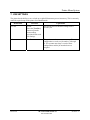
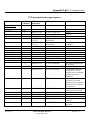
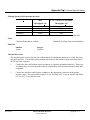
4. BARCODE
Use this option to print a USPS (US Postal Service Postnet Barcode) barcode on the piece of media and to
place it above or below the record. For information on the requirements to print a UPSP barcode, see
Appendix G.
Menu Items
A. Location
Selections
Explanation
Lower Right
Corner
Select the US Postal Service Postnet Barcode
options from the following selections:
Above Address
Below Address
Off
LOWER RIGHT CORNER: The barcode is always
printed in the lower right corner of the media. Note:
This option is disabled when the selected
Orientation is Invert.
ABOVE ADDRESS: Prints the barcode in the
address block above the first line of the address on
the media.
BELOW ADDRESS: Prints the barcode below the
last line of the address in the address block on the
media.
OFF : Stops the printing of a Delivery Point
Barcode (DPBC) on the media.
Note: This option has the printer generate the USPS
barcode.
B. 5 Digit On/Off
Revision A
ON or OFF
This item prints a 5 Digit barcode for a five digit zip
code. Note: Only a 5 Digit barcode is printed for a
five digit zip code when enabled. A Delivery Point
Bar Code cannot be generated from a five digit zip
5K-LE OWNERS MANUAL
P/N 90-00852-001
Section 6 - 6
Printer Menu System
code.
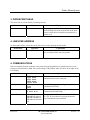
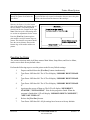
5. ADDRESS RECOVERY
When something goes wrong while printing use this option to direct the printer to re-print up to 20 of the
last records or to clear the printers memory of all records.
Menu Items
A. Get Addresses
Selections
Explanation
NONE TO RECOVER
or
This option retrieves up to 20 records from the data
buffer.
00 to 20
The display will say 00: and show the first 16
characters of the last address printed. If NONE TO
Press the [Enter]
RECOVER is first displayed then the data buffer is
button to select the
record and advance the empty.
display to the next to
last record.
B. Clear Memory
YES or NO
This option removes any data left in the data buffer.
The alternative way to clear data from the Data
Buffer is to press the [+] plus and [–] minus buttons
simultaneously.
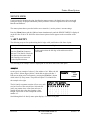
6. CLEAR COUNTER
Use this option to clear the piece (batch) counter back to zero.
Menu Items
Selections
YES or NO
Revision A
Explanation
This option resets the counter to zero on the display.
Select No to leave the current number of pieces
printed (pcs) on the LCD display.
5K-LE OWNERS MANUAL
P/N 90-00852-001
Section 6 - 7
Printer Menu System
7. JOB SETTINGS
The printer has the ability to save or load up to eight different menu presets in memory. This is extremely
useful for a quick setup of the printer for redundant tasks.
Menu Items
A. Load
Selections
Explanation
1 to 8
Press the [Test Env.]
button to print the
menu settings
associated with saved
Job Settings.
B. Save
Revision A
1 to 8
This option retrieves the menu settings from a
previous job.
This option saves the current menu setup. The menu
configuration is saved as a job number (1 through
8). The operator must keep a record of these
configurations and the job number that was
assigned.
5K-LE OWNERS MANUAL
P/N 90-00852-001
Section 6 - 8
Printer Menu System
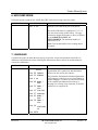
SETUP MENU
The Industrial Printer has a Setup Menu that lets you configure the Industrial Printer so it will function
correctly with the computer and computer software. Use the Setup Menu to also display the menus in
another language besides English. Hold down the [Menu] button for two (2) seconds until SETUP
MENU is displayed on the first line of the LCD. Select the desired menu option when it appears on the
second line of the LCD.
1. HEAVY MEDIA MODE
Enable this option for the printer when the media stack exceeds 10 pounds (4.54 kg).
Menu Items
Selections
Explanation
On or Off
Use this option to increase the force used to feed the
media. Note: Whenever the transport motor torque
is increased the media throughput will decrease
approximately 10%.
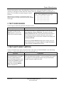
2. TEST PRINT HEAD
Before using this option, verify the media is loaded in the input bin so a test pattern can be printed. A
diagonal line will print across the media with a small solid box. If a gap is present within the diagonal
line, one or more nozzles of the ink jet cartridge maybe blocked and need to be cleaned. Clean the ink jet
cartridge by performing a purge (see menu option below). If the purge does not clear the nozzles, then
remove the Ink Jet Cartridge. See chapter 3 on how to remove and install an ink jet cartridge. Clean the
nozzles with a dry soft cotton cloth or one moistened with water.
Menu Items
Selections
Explanation
Print a test
pattern? Yes or
Press the + (YES) button to print the test pattern or
press the - (NO) button to disable this option.
No
Revision A
5K-LE OWNERS MANUAL
P/N 90-00852-001
Section 6 - 9
Printer Menu System
3. PURGE PRINT HEAD
This menu item is to clean the ink jet cartridge nozzles.
Menu Items
Selections
Explanation
Yes or No
The purge process fires all the ink jet nozzles into a
sled to dislodge and clear any dried ink on the print
nozzles. Often this will return the print quality to a
normal level.
4. LINES PER ADDRESS
Set the number of lines of text the record will consist of when printing onto the media.
Menu Items
Selections
Explanation
1 to 66
Set the number of lines to match the number of lines
in a record that will be sent to the printer.
4. COMMUNICATIONS
Data is transmitted from the computer to the printer through the parallel port (parallel interface) or the
serial port (serial interface). Note: The current settings of the SERIAL menu are shown to the right on the
LCD display.
Menu Items
A. Baud Rate
B. Parity
C. Word Length
D. Line Termination
Revision A
Selections
Explanation
1200 Baud
2400 Baud
4800 Baud
9600 Baud
19200 Baud
Odd
Even
None
7 Data Bits
8 Data Bits
Select the baud rate that matches the computers for
communication over the serial port
CR=CR;LF=LF
CR=CR+LF;LF=LF
CR=CR;LF=CR+LF
CR=CR+LF;LF=CR+
LF
The typical software line termination is CR = CR;
LF = LF. If your software is not typical then the
Line Termination can be modified.
Use the following steps to change the serial
communications Parity.
Use the following steps to change the serial
communications word length
5K-LE OWNERS MANUAL
P/N 90-00852-001
Section 6 - 10
Printer Menu System
6. HEX DUMP MODE
Utilize this option to print the raw ASCII data (HEX Code) that is being sent to the printer.
Menu Items
Selections
Explanation
Off or On
Prints the ASCII data being sent to the printer.
The media width must be a minimum of 7 1/2” or
191 mm when running in HEX Mode. The page
orientation, margins and number of lines are defined
by the ADDRESS LAYOUT and
LINES/ADDRESS. The maximum number of
usable lines is 16.
Note: Clear the data buffer before sending data to
the printer.
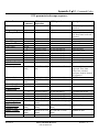
7. LANGUAGE
Customize the printer to match the keyboard of your printer, convert measurements from inches to
millimeters and translate the menus from English. Most menus that use inches for measurements are
converted to millimeters.
Menu Items
A. Symbol Set
Selections
Explanation
ISO 6 ANSI
ASCII
ISO 69 FRENCH
ISO 21 GERMAN
ISO 4 UK
ISO 60 NORW /
DAN
ISO 11 SWED /
FIN
Match the printers’ International Standards
Organization (ISO) symbol sets and substitution
tables to the one used by the software.
The printer has International Standard Organization
(ISO) language symbol sets to use when printing in
another language. A symbol set contains collections
of the symbols and characters that make up a
language. For a listing of the characters for the ISO
symbol sets see Appendix D.
ISO 15 ITALIAN
ISO 17 SPANISH
ISO 61 NORW /
DAN
ISO 10 SWED /
FIN
ISO 16
PORTUGUE
SE
ISO 8859
Revision A
5K-LE OWNERS MANUAL
P/N 90-00852-001
Section 6 - 11
Printer Menu System
Menu Items
Selections
Explanation
ROMAN 8
WINDOWS LATIN 1
PC 8
B. Inch / Millimeter
C. Menu Language
Inch or
Millimeters
ENGLISH
GERMAN
FRENCH
ITALIAN
SPANISH
DUTCH
POLISH
This option converts the printer measurement
system from inches to millimeters and vice versa.
This option will convert the Main Menu and Setup
Menu to their translations in the listed languages.
8. ENV. (ENVELOPE) FEED DELAY
This option may be required to extend drying time for the ink when printing on very glossy media. This
option reduces the overall throughput by increasing the time before the next piece is printed. Use the
following steps to change the time between printing records.
Menu Items
Selections
00 to 30
Seconds
Explanation
Increase or decrease the amount of time before the
next piece is drawn from the input bin.
9. ENV. (ENVELOPE) AUTO EJECT
Use this option to automatically eject the last envelope in your file. Use the following steps to eject a
blank piece of media between batch jobs.
Menu Items
Selections
On or Off
Revision A
Explanation
When this option is enabled a blank envelope will
be ejected between batch jobs.
5K-LE OWNERS MANUAL
P/N 90-00852-001
Section 6 - 12
Printer Menu System
10. ROM REVISION#
This option displays the Firmware Revision installed in the printer and the total number of accumulated
print cycles (maintenance count).
Menu Items
Revision A
Selections
Explanation
Press the [Test] button
when ROM REV. is
displayed on the LCD.
A list of the Main
Menu and Setup Menu
settings is printed on
two pieces of media.
The LCD display will give a momentary view of the
ROM Revision and the Maintenance count.
5K-LE OWNERS MANUAL
P/N 90-00852-001
Section 6 - 13
Printer Menu System
SERVICE MENU
Use this menu for adjusting the print, checking the transport motor, the shuttle motor, the sensors and
testing the display for proper functionality and to perform a corrective alignment for the Lower Right
Barcode and addresses.
The menu options that are preceded with a star or Asterisk (*) are the printers’ current settings.
Press the [Menu] button and the [-] Minus button simultaneously until the SERVICE MENU is displayed
on the first line of the LCD. Select the desired menu option when it appears on the second line of the
LCD.
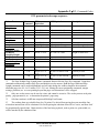
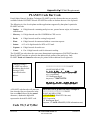
1. LEFT JUSTIFY
The following steps are for synchronizing the left edge or left justification of the lines of print.
Selections
0 to 9
Press the [Test Env.] button to
print out a Test Pattern. Check the
Test Pattern to determine which
Print Cartridges are in need of
Vertical Synchronization.
Explanation
Use this option when the left edge of the address needs left
justification.
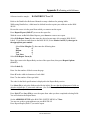
The following is an example of how to adjust print so each lines starts in the same place.
Example:
On the right is an example of a three (3) line address of A's. Where the left
edge of line 1 did not align with line 2 which did not align with line 3.
Example:
Print out an adjust print Test Pattern by pressing the [Test Env.] button
while in the Left Justify menu. The printer will print a Test Pattern like
the example to the right.
Select the pattern
with the vertical line
The left justify test pattern consists of four rows, each
0 1 2 3 4 5 6 7 8 9
row has a series of ten vertical lines. Select the left
| | | | | | | | | |
justify test pattern where a line from each row is
|
| | | | | | | | |
printed directly above the other forming a long
|
| | | | | | | | |
straight vertical line. In this example the correct
|
|
| | | | | | | |
number is 5.
AAAA
AAAA
AAAA
Scroll through the Left Justify menu option displays 5 is on the LCD panel.
Revision A
5K-LE OWNERS MANUAL
P/N 90-00852-001
Section 6 - 14
Printer Menu System
Enter the menu option to move the setting down. Enter the new value into the printers memory. An
Asterisk (*) will appear in front of the new selection. Press the [Test Env.] button to print another Test
Pattern. The Test Pattern is printed using the entered
When correct pattern is selected
all lines should be straight
selection.
When the correct numeral is selected the center Test
Pattern will have ten long vertical lines like the example
to the right.
0
|
|
|
|
|
1
|
|
|
|
|
2
|
|
|
|
|
3
|
|
|
|
|
4
|
|
|
|
|
5
|
|
|
|
|
6
|
|
|
|
|
7
|
|
|
|
|
8
|
|
|
|
|
9
|
|
|
|
|
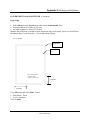
2. TEST PAPER SENSOR
Use this option to check the operation of the photo sensor.
Selections
Press the [Enter] button to select
this option. As soon as, the
[Enter] button is pressed, the
printer will be in the test mode.
Explanation
The state of the sensor is represented on the LCD by the message
Sensor Blocked or Sensor Unblocked. The display will read
Sensor Unblocked when the sensor path between both sensors is
clear. When the sensor has media in the path, or the sensor is
covered with paper dust, or the sensor is defective the display will
read Sensor Blocked.
If the message Sensor Blocked remains after cleaning, call your
Service Representative for repairs. Note: For further information
see the Cleaning And Maintaining Section.
3. TEST SHUTTLE MOT. (MOTOR)
Use the test shuttle motor option to help determine if the motor or Print Head Holder is not functioning
properly i.e. slams on the opposite side, moves inconsistently, etc.
Selections
Explanation
Press the [+] Plus button to move
the print head holder to the right.
Press the [-] Minus button to
move the print head holder to the
left. Press the [Test Env.] button
to start the Continuous Shuttle
Motor Test. Press the [Menu]
button to stop the test.
The Test Shuttle Motor is used to check the left and right movement
of the print head holder assembly. Use the continuous test to check
for a repetitive left and right movement of the print head holder
assembly along the length of the shaft.
Revision A
5K-LE OWNERS MANUAL
P/N 90-00852-001
Section 6 - 15
Printer Menu System
4. TEST PAPER MOTOR
Use the test paper motor option to help determine if the motor or paper feeding system is not functioning
properly i.e. rollers not turning, strange noises, etc.
Selections
Press the [+] Plus button to move
the media 1 inch (2.54 cm). Press
the [-] minus button to move the
media 1/150 of an inch (0.017
cm).
Explanation
The test paper motor option tests the feeding mechanism of the
printer by controlling the transport motor. The transport motor will
feed the paper through the printer in small increments 1/150 inch
(0.017 cm) or in large increments 1 inch (2.54 cm).
5. TEST DISPLAY
Use the test display option to help determine if the LCD display is not functioning properly i.e. missing
characters, strange characters, missing segments, etc.
Selections
Press the [Enter] button to select
this option. As soon as, the
[Enter] button is pressed, the
printer will be in the test mode.
Explanation
The test display will scroll characters across the top and bottom of
the LCD display.
EXAMPLE:
The LCD display will scroll the lower case alphabet and numerals (09) across the top line, while the bottom line will scroll control
characters and the numerals. The Test function will cycle twice and
return to the Service Menu. See example below for LCD display
sample test message.
abcdefghijklmnopqrstuvwxyz 0123456789
\->!#$%&*()_+- =[]:;'<>/? 0123456789
Example of LCD display with
characters scrolling across
6. ENV. (ENVELOPE) BOTTOM EDGE
Utilize this option if the bar-code is out of specification ( 1/4 inch (0.635 cm) from the bottom edge of the
media to the bottom edge of the Bar-code [+/- 1/16 inch or +/- 0.159 cm]).
Selections
0 to 50
Press the [Test Env.] button to
print a test pattern. Press the
Revision A
Explanation
This option will raise or lower the print from the bottom edge of the
envelope.
Adjust the bar-code Bottom Edge Distance by increasing or
5K-LE OWNERS MANUAL
P/N 90-00852-001
Section 6 - 16
Printer Menu System
[Env. Eject] button to eject the
printed test pattern from under the
exit sliders.
decreasing the number from 0 to 50. Each number increase moves
the print and bar-code up and each number decrease moves the print
and bar-code down from the bottom of the envelope.
Measure the distance from the bottom
edge of the media to the bottom edge of
the Test Pattern. The pattern printed
should look like the example on the right.
Note: If the bar-code is fluctuating, then
see section on adjustments for the sensor.
Press the [Test Env.] button again to
print another envelope bottom edge test
pattern. This time the test pattern should
have the correct distance between the
bottom edge of the media and the test
pattern.
Resetting the Printer
The various selections made in all three menus: Main Menu, Setup Menu, and Service Menu,
can be reset to their factory default values.
Perform the following steps to reset the printer to the Factory Default settings:
1.
Depress and hold down the [Test Env.] button simultaneously.
2.
Turn Power OFF then ON. The LCD will display “MEMORY RESET PHASE
1”.
3.
Turn Power OFF then ON. The LCD will display “MEMORY RESET PHASE
2”.
4.
Turn Power OFF then ON. The LCD will display “MEMORY RESET PHASE
3”.
5.
Again turn the power off then on. The LCD will display “MEM RESET
STARTED”, “INITIALIZING”. Wait for the program to finish. When the
program is finished the LCD will display “MEMORY RESET COMPLETE”,
“SHUT OFF THEN ON”.
6.
Release the [Test Env.] button.
7.
Turn Power OFF then ON. All job settings have been set to factory defaults.
Revision A
5K-LE OWNERS MANUAL
P/N 90-00852-001
Section 6 - 17
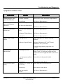
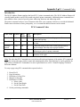
Troubleshooting and Diagnostics
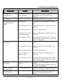
Symptoms & Solutions Chart
SYMPTOM
Nothing happens when
power is switched on
LCD display shows solid
line or miscellaneous
characters
Motor on, Feed Roller
doesn't turn
Printer is not Feeding
Media
Feed Problems
(Intermittent)
CAUSE
No Power to printer.
Check Power Cord. Call Service Representative.
Fuse is blown
Problems with Eprom
Call Service Representative.
Call Service Representative.
Bad Processor Main Board
Loose set screw on Motor
Pulley.
Revision A
Call Service Representative.
Call Service Representative.
Mechanical Clutch broken
Call Service Representative.
Broken belt
Feed Gap not set
Call Service Representative.
Adjust separators ("H" Blocks) to media
thickness.
Media out of specification
Thickness: Minimum .003" (0.0762 mm),
Maximum 1/16” (1.587 mm)
Feed Ramp not used.
Paper dust present (yellow
residue)?
Feed Problems (Multi
feeds)
SOLUTION
No metal clasps (staples, paper clips etc.)
on media.
Adjust the media on the incline plane of the Feed
Ramp. Check "H" block gap. Adjust the Wire
Form to the correct height and in the center of the
media.
Clean roller with denatured Alcohol.
Blow sensors clean with air.
Sensors dirty
Separators ("H" blocks) not Adjust separators to media thickness
set correctly
Sensors dirty
Blow sensors clean with air.
Brake not properly
adjusted
Call Service Representative.
5K-LE OWNERS MANUAL
P/N 90-00852-001
Section 7 - 1
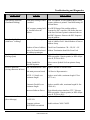
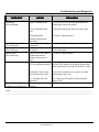
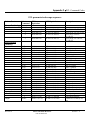
Troubleshooting and Diagnostics
SYMPTOM
Print Quality Problems
(No print)
CAUSE
Ink Jet Cartridge problems
SOLUTION
Purge ink jet cartridge.
Clean cartridge with soft cotton cloth and water.
Change to a known good cartridge.
Print Head Holder broken
Call Service Representative.
Non Uniform Print Quality
Print Head Holder broken
Call Service Representative.
Ink Streaking on Media
Print Head Adjustment
Lever set too low
Lift lever up to raise the Print Head Holder.
Ink on Exit Slider Rollers
Print Head Adjustment
Lever set too high
Clean Rollers with water to remove ink.
Lower lever down to lower the Print Head Holder
Ink Print Quality is not
sharp
Print is Skewed
(Skew Specification +/- 2
1/2 degrees of bottom
edge.)
Print Quality Problems
(Gray Print)
Revision A
Change to a typical white wove bonded paper
Media unsuitable
Separators ("H" blocks) not Reset each of the H-Blocks.
set correctly
Wire Form set wrong
Set the Wire Form to the center of the media.
Sliding Fence set wrong
Adjust the fence to within 1/16" (0.16 cm) of the
media.
Exit Slider Rollers set
wrong
Adjust exit roller to within 1/4" (6.35 mm) from
outside edges of media.
Wiper Assembly bent or
Idler Assembly set wrong
Replace Wiper Assembly or fix spring tension on
Idler Assembly.
Ink Jet Cartridge empty
Ink supply too low, Replace Ink Jet Cartridge
5K-LE USERS MANUAL
P/N 90-00852-001
Section 7 - 2
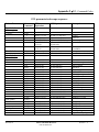
Troubleshooting and Diagnostics
SYMPTOM
Print Quality Problems
(Unwanted Bolding)
Print Quality Problems
(Addresses "walking")
Interface problems
(Garbage print)
Interface problems
(Losing characters & lines)
CAUSE
SOLUTION
Main Menu setting of Bold
is enabled
Press Test Button. A bold Standard Bryce Office
Systems Address is printed. Turn Bold setting off
in Main Menu.
ESC sequence turning bold
on, located before the
address
Do a HEX Dump of the problem address.
Examine for ESC sequence (1B) before the start
of the line. Reference printer command codes to
find ESC Sequence. Remove the ESC Sequence
from the address.
Do Hex Dump and count carriage returns and line
feeds of Address Field. Match number of lines to
Address Setup.
Incorrect address setup
Number of lines of address
varies. No Form Feed used
for address termination.
Incorrect Software Driver
Check Line Termination CR = CR, LF = LF.
Address Termination should be Form Feed
Typical dumb printer interface (TTY, Teletype,
DOS text printer, Generic printer) or HP Laserjet
series II, W700 or 9K-L.
Select correct Symbol Set from printers Setup
Wrong Symbol Set
Menu.
selected in printer.
Bad communications Cable Replace internal or external cable
Bad main processor board
Call Service Representative.
RS232 -C (Serial) over
maximum length
Replace serial cable, maximum length 15 feet
(457.2 cm)
Centronic (Parallel) over
maximum length
Replace parallel cable, maximum length 10 feet
(304.8 cm)
Typical dumb printer interface (TTY, Teletype,
DOS text printer, Generic printer) or HP Laserjet
series II, W700 or 9K-L.
Bad communications Cable Replace cable or Call Service Representative.
or CPU I/O
Incorrect Software Driver
Communication Overrun
(Error Message)
Computer software
XON/XOFF not enabled.
Revision A
Enable software XON / XOFF.
5K-LE USERS MANUAL
P/N 90-00852-001
Section 7 - 3
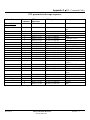
Troubleshooting and Diagnostics
SYMPTOM
CAUSE
Framing Error
(Error Message)
Incorrect Word Length /
Parity / Baud Rate
Parity Error
(Error Message)
Parallel Interface, printer is
not printing (Printer
Halted)
Incorrect Parity setting
Bad data sent
SOLUTION
Turn printer off then back on and send data again.
Reset settings for Baud rate in printer or
computer.
Turn printer off then back on and send data again.
Reset Parity rate in printer or computer.
Turn printer off, then turn printer on and send
again.
Bad communications Cable Replace parallel cable, maximum length 10 feet
(304.8 cm)
Serial Interface, printer is
not printing
Bad main processor board
Call Service Representative.
Centronic (Parallel) Cable
over maximum length
Replace parallel cable, maximum length 10 feet
(304.8 cm)
Incorrect Software Driver
Typical dumb printer interface (TTY, Teletype,
DOS text printer, Generic printer) or HP Laserjet
series II, W700 or 9K-L.
Turn printer off, then turn printer on and send
again.
Bad data sent
Bad communications Cable Replace serial cable, maximum length 15 feet
(457.2 cm)
Bad main processor board
Call Service Representative.
RS232 -C (Serial) over
maximum length
Replace serial cable, maximum length 15 feet
(457.2 cm)
Typical dumb printer interface (TTY, Teletype,
DOS text printer, Generic printer) HP Laserjet
series II, W700 or 9K-L.
Font Cartridge not installed Verify the Font Cartridge label is facing the
correctly
operator.
Verify the Font Cartridge is inserted all the way
into the Font Cartridge Slot.
Software Margin incorrect Top Line of the Address is above the edge of the
media. Move the location of the address down.
Software Margin incorrect The Address is below the Bottom edge of the
media. The bottom edge margin must be
increased.
Incorrect Software Driver
Optional Fonts not
functioning
Address Too High
(Error Message)
Address Too Low
(Error Message)
Revision A
5K-LE USERS MANUAL
P/N 90-00852-001
Section 7 - 4
Troubleshooting and Diagnostics
SYMPTOM
Shuttle Jam
(Error Message)
Out of Memory
(Error Message)
Font Card Removed
(Error Message)
Battery Error
(Error Message)
No Barcode
Barcode (lower right) is
wandering (up and down)
CAUSE
SOLUTION
Shuttle is hitting media
Lift lever up to raise the Print Head Holder so
head height is above the media.
Lower Print Head Shaft
dirty.
Clean shaft with alcohol and soft cotton cloth.
Print Head Holder
bushings clogged with
paper dust
Overuse of graphics / page
information
Connection to font card
incomplete.
Battery is low and cannot
maintain the printers
settings when powered
down.
Address margin below 5/8"
(1.6 cm) minimum distance
Call Service Representative.
Invalid Zip Code or more
data following Zip Code.
Check Zip Code and correct, remove any data
following the Zip Code.
Five (5) Digit Zip Code
turned off.
Belt tension is not adjusted
correctly.
The 5 digit zip code option in the print Main
Menu is Off.
Call Service Representative.
Turn printer off then send again.
Insert Font Card, turn printer off, then turn printer
on and send again.
Call Service Representative.
Lower Right Barcode, the distance between the
last line of the address field and the bottom edge
of the media must be at least 5/8 inches (1.6 cm).
Notes: ___________________________________________________________________________________
_________________________________________________________________________________________
Revision A
5K-LE USERS MANUAL
P/N 90-00852-001
Section 7 - 5
Appendix A • Bryce Office Systems 5K-LE MAIN MENU Flow Chart
----MAIN MENU---1. Address Layout
Address Layout
A. Dist to Right
Address Layout
B Dist to Bottom
DIST TO RIGHT
*4.50 in
DIST TO BOTTOM
*2.00 in
+MORE
-LESS
+MORE
-LESS
DIST TO RIGHT
*115 mm
DIST TO BOTTOM
*50 mm
+MORE
-LESS
+MORE
-LESS
Address Layout
LINE SPACING
LINE SPACING
LINE SPACING
3 lines/inch
4 lines/inch
6 lines/inch
C. Line Spacing
Address Layout
ORIENTATION
ORIENTATION
*Normal
Invert
D. Orientation
c Substituted Address Layout menu selections when ORIENTATION is in Invert.
LEFT MARGIN
+MORE LEFT MARGIN
+MORE
c Address Layout
*4.50 in
-LESS *115 mm
-LESS
A. Dist to Left
TOP MARGIN
+MORE TOP MARGIN
+MORE
c Address Layout
*2.00 in
-LESS *50 mm
-LESS
B Dist to Top
LINE SPACING
8 lines/inch
LINE SPACING
*Automatic
----MAIN MENU---2. Print Quality
Print Quality
*Executive
Print Quality
Letter
Print Quality
Draft
----MAIN MENU---3. Font
FONT
dA. Name
FONT NAME
Sans Serif
FONT
B. Size
FONT
C. Width
FONT
D. Bold
FONT
E. Italic
FONT
F. Outline
FONT NAME
e
*Courier
FONT NAME
e
Code 39
FONT SIZE
+LARGER
*12 point
-SMALLER
FONT WIDTH
*Normal (100%)
BOLD
*Off
ITALIC
*Off
OUTLINE
*Off
FONT WIDTH
Thin (75%)
BOLD
On
ITALIC
On
OUTLINE
On
FONT WIDTH
Condensed (50%)
FONT WIDTH
Wide (125%)
BARCODE
A. Location
BARCODE
B. 5 Digit On/Off
BARCODE LOCATION
*Off
5 DIGIT BARCODE
*Off
BARCODE LOCATION
Above Address
5 DIGIT BARCODE
On
BARCODE LOCATION
Below Address
BARCODE LOCATION
Lower Right Corner
----MAIN MENU---4. Barcode
e
FONT NAME
Roman
e
FONT NAME
Ocr A
e
FONT NAME
Ocr B
e
FONT WIDTH
Expanded (150%)
d To print a list of accessible fonts in their typeface, press the [Test Env.] button when in the FONT menu and
the selection A. Name is displayed.
e To print a fonts’ character table, press the [Test Env.] button when in the FONT NAME sub-menu and the name of
the desired font is displayed. The Code 39 font is not displayed or a selectable font.
Revision A
5K-LE OWNERS MANUAL
P/N 90-00852-001
Section A - 1
Appendix A • Bryce Office Systems 5K-LE MAIN MENU Flow Chart
ADDRESS RECOVERY
----MAIN MENU---5.Address Recovery A. Get Address
ADDRESS RECOVERY
B. Clear Memory
----MAIN MENU---6. Clear Counter
Clear address
(pcs) counter?
----MAIN MENU---7. Job Settings
JOB SETTINGS
A. Load
JOB SETTINGS
B. Save
Revision A
02: John P. Jones
NONE TO RECOVER.
Hit Recover ENTER to
Clear the
+YES
Address Buffer? -NO
+YES Address counter
-NO
cleared. Pieces=0
Load Settings
from Job #3?
Save Settings
as Job #6?
+MORE
-LESS
+MORE
-LESS
Printer is set for
Job #3.
Job #6 has been
saved.
5K-LE OWNERS MANUAL
P/N 90-00852-001
Section A - 2
Appendix A • Bryce Office Systems 5K-LE SETUP MENU Flow Chart
----SETUP MENU---1. Heavy Media Mode
HEAVY MEDIA MODE
* Off
HEAVY MEDIA MODE
On
----SETUP MENU---2. Test Print Head
Print a test
Pattern?
+YES Please wait. Test
-NO pattern is printing
----SETUP MENU---3. Purge Print Head
Purge Print
Head?
+YES Please wait. Print
-NO
head being purged.
LINES/ADDRESS+MORE
----SETUP MENU----LESS
4. Lines Per Address *66
----SETUP MENU---5.Communications
SERIAL
A. Baud Rate
SERIAL
B. Parity
SERIAL
C. Word Length
SERIAL
D. LINE TERMINATION
BAUD RATE
1200 Baud
PARITY
*None
WORD LENGTH
7 Data Bits
LINE TERMINATION
*CR=CR, LF=LF
----SETUP MENU---6. Hex Dump Mode
HEX DUMP MODE
*Off
HEX DUMP MODE
On
----SETUP MENU---7. Language
LANGUAGE
A. Symbol Set
ISO CHARACTER SET
*ISO 6 ANSI ASCII
ISO CHARACTER SET
ISO 15 ITALIAN
ISO CHARACTER SET
ROMAN 8
MEASUREMENT UNITS
*Inch
DISPLAY LANGUAGE
*English
DISPLAY LANGUAGE
Polish
LANGUAGE
B. Inch/Millimeter
LANGUAGE
C. Menu Language
----SETUP MENU---8.Env. Feed Delay
FEED DELAY
*0.0 SEC.
----SETUP MENU---9.Env. Auto Eject
AUTO EJECT MODE
*On
BAUD RATE
2400 Baud
PARITY
Even
WORD LENGTH
*8 Data Bits
LINE TERMINATION
CR=CR+LF LF=LF
ISO CHARACTER SET
ISO 69 FRENCH
ISO CHARACTER SET
ISO 17 SPANISH
ISO CHARACTER SET
WINDOWS LATIN 1
MEASUREMENT UNITS
Millimeter
DISPLAY LANGUAGE
German
BAUD RATE
4800 Baud
PARITY
Odd
BAUD RATE
* 9600 Baud
LINE TERMINATION
CR=CR LF=CR,LF
LINE TERMINATION
CR=CR+LF LF=CR+LF
ISO CHARACTER SET
ISO 21 GERMAN
ISO CHARACTER SET
ISO 61 NOR / DAN
ISO CHARACTER SET
PC 8
ISO CHARACTER
ISO 4 UK
ISO CHARACTER
ISO 10 SWED /
ISO CHARACTER
CP 1250
SET ISO
ISO
SET ISO
FIN ISO
SET
DISPLAY LANGUAGE
French
DISPLAY LANGUAGE
Italian
BAUD RATE
19200 Baud
CHARACTER SET
60 NORW / DAN
CHARACTER SET
16 PORTUGUESE
DISPLAY LANGUAGE
Spanish
ISO
ISO
ISO
ISO
CHARACTER SET
11 SWED / FIN
CHARACTER SET
8859
DISPLAY LANGUAGE
Dutch
+MORE
-LESS
AUTO EJECT MODE
*Off
----SETUP MENU---ROM REV. = R123456 f
10.Rom Revision #
MAINT COUNT =1234567
f To print a list of the Main Menu, Setup Menu and Service Menu settings, press the [Test Env.] button when ROM
REV is displayed.
Revision A
5K-LE OWNERS MANUAL
P/N 90-00852-001
Section A - 3
Appendix A • Bryce Office Systems 5K-LE SERVICE MENU Flow Chart
---SERVICE MENU--1. Left Justify
LEFT JUSTFY
5
+MORE
-LESS
PAPER SENSOR TEST
---SERVICE MENU--2. Test Paper Sensor Sensor Blocked
PAPER SENSOR TEST
Sensor Unblocked
SHUTTLE TEST +RIGHT
---SERVICE MENU---LEFT
3. Test Shuttle Mot.
CONTINUOUS TEST
PRESS ANY KEY TO END.
PAPER MOTOR
---SERVICE MENU--4. Test Paper Motor
---SERVICE MENU--5. Test Display
abcdefghijklmnopqrst
ABCDEFGHIJKLMNOPQRST
BOTTOM EDGE
---SERVICE MENU--6. Env. Bottom Edge
Revision A
+1 in.
-1/150
+MORE
-LESS
scrolls for 3
seconds then stops
Press the [Test Env.] button to print a bottom edge test pattern. Check the distance
from the pattern to the edge of the media. Requires two pieces of media.
5K-LE OWNERS MANUAL
P/N 90-00852-001
Section A - 4
Appendix B Hex Chart
HEX CHART
MSB
DECIMAL
HEX
0
1
2
3
4
LSB
5
6
7
8
9
10
11
12
13
14
15
0
1
2
3
4
5
6
7
8
9
A
B
C
D
E
F
0
16
32
48
64
80
96
112
0
1
2
3
4
5
6
7
NUL
DLE
SP
0
@
P
`
p
SOH
DC1
!
1
A
Q
a
q
STX
DC2
"
2
B
R
b
r
ETX
DC3
#
3
C
S
c
s
EOT
DC4
$
4
D
T
d
t
ENQ
NAK
%
5
E
U
e
u
ACK
SYN
&
6
F
V
f
v
BEL
ETB
'
7
G
W
g
w
BS
CAN
(
8
H
X
h
x
HT
EM
)
9
I
Y
i
y
LF
SUB
*
:
J
Z
j
z
VT
ESC
+
;
K
[
k
{
FF
FS
,
<
L
\
l
|
CR
GS
-
=
M
]
m
}
SO
RS
.
>
N
^
n
~
SI
US
/
?
O
_
o
DEL
HEX CHART
Example: The capital letter A is a HEX 41. Find the letter A on the above chart, and look
towards the top of the chart (MSB) and the locate the HEX number 4. Then look to
the left side of the chart (LSB) and locate the Hex number 1. Therefore the HEX
number is MSB 4 and LSB 1= 41.
Revision A
5K-LE OWNERS MANUAL
P/N 90-00852-001
Section B -1
Appendix C PCL Command Codes
Introduction
The 5K-LE Address Printer emulates the listed PCL 5 printer command codes. The 5K-LE Address Printer will
virtually handle media as an HP1200 would using these printer commands. Additional printer commands have
been added to allow control of special printer addressing functions and addressing needs.
The printer command codes are sets of characters that allow your computer software to override the Industrial
Printer menu selections as fonts, print quality, etc. so customized address formats can be created.
PCL Command Codes
Code Name
Symbol
<LF>
HEX
Value
0A
DEC
Value
10
Line Feed
Form Feed
<FF>
0C
12
Carriage
Return
Escape
<CR>
0D
13
<Å>
1B
27
Space
<SP>
20
32
Description
Causes the printer to advance the paper one line at
current line spacing.
Causes the printer to advance the paper to the next top
of form.
Causes the printer to move the current print position to
the left margin. Does not cause a paper advance.
Indicates to the printer that the characters immediately
following are part of a printer command.
Causes the printer to move the current print position one
character to the right.
Note: The order that PCL Commands are received can affect the performance of the printer. PCL commands
sent in the wrong order may produce erratic and unanticipated results. The following is a quick guideline for
what order to send the PCL commands. For more explicit details see a PCL 5 Printer Language Technical
Reference Manual.
To setup a page using PCL commands the expected order is:
1.
2.
3.
4.
5.
Reset (Esc E)
Page Orientation
Definition of a Page Size
Margins on the page
Definitions of a Font
a. Select a font
b. Set the Font Height
c. Set the Font Pitch
6. Set the positioning commands
Revision A
5K-LE OWNERS MANUAL
P/N 90-00852-001
Section C - 1
Appendix C PCL Command Codes
PCL parameterized escape sequences
Printer Feature
Printer
Command
HEX
Equivalent
DEC Equivalent
Description
ÅE
ÅH
1B 45
1B 48
027 069
027 072
Defines reset conditions
Performs reset plus clears all
permanent macros, fonts,
and address recovery buffer
Page Size Default
Page Size Executive
Å&l0A
Å&l1A
1B 26 6C 30 41
1B 26 6C 31 41
027 038 108 048 065
027 038 108 049 065
Page Size Letter
Å&l2A
1B 26 6C 32 41
027 038 108 050 065
Page Size Legal
Page Size A4
Å&l3A
Å&l26A
027 038 108 051 065
027 038 108 050 054 065
Page Size Mon Env
Å&l80A
Page Size #10 Env
Å&l81A
Page Size DL Env
Å&l90A
Page Size C5 Env
Å&l91A
Page Size B5 Env
Å&l100A
Page Size 9.4” x 15”
Å&l101A
Left Margin
Å&a#L
1B 26 6C 33 41
1B 26 6C 32 36
41
1B 26 6C 38 30
41
1B 26 6C 38 31
41
1B 26 6C 39 30
41
1B 26 6C 39 31
41
1B 26 6C 31 30
30 41
1B 26 6C 31 30
31 41
1B 26 61 #..# 4C
#10 Envelope values
7.25 x 10.5 inches (18.3 x
26.7 cm)
8.5 x 11 inches (21.6 x 27.9
cm)
8.5 x 14 inches (21.6 x 35.6)
210 x 297 mm
Clear Horiz Margins
Top Margin
Page Length c
Text Length
Horiz Motion Index
(HMI)
Å9
Å&l#E
Å&l#P
Å&l#F
Å&k#H
1B 39
1B 26 6C #..# 45
1B 26 6C #..# 50
1B 26 6C #..# 46
1B 26 6B #..# 48
027 057
027 038 108 #..# 069
027 038 108 #..# 080
027 038 108 #..# 070
027 038 107 #..# 072
Initialization
Reset
Hard Reset
Page Control
Revision A
027 038 108 056 048 065
027 038 108 057 048 065
7.5 x 3.88 inches (19.1 x 9.9
cm)
9.5 x 4.1 inches (24.1 x 10.4
cm)
220 x 110 mm
027 038 108 057 049 065
229 x 162 mm
027 038 108 049 048 048
065
027 038 108 049 048 049
065
027 038 097 #..# 076
238 x 104 mm
027 038 108 056 049 065
5K-LE OWNERS MANUAL
P/N 90-00852-001
9.4 x 15 inches (23.9 x 38.1
cm)
# of Columns. Defined by
current HMI.
# of Dots from origin
# of Lines
# of Lines
# of 1/120 inch (1/47 cm)
Section C - 2
Appendix C PCL Command Codes
PCL parameterized escape sequences
Printer Feature
Printer
Command
HEX
Equivalent
DEC Equivalent
Description
Å&l#C
1B 26 6C #..# 43
027 038 108 #..# 067
# of 1/48 inch (1/19 cm)
Å&l#D
Å&l0H
Å&l6H
1B 26 6C #..# 44
1B 26 6C 30 48
1B 26 6C 36 48
027 038 108 #..# 068
027 038 108 048 072
027 038 108 054 072
# of lines per inch
Effects feed mode selection
Å&l9H
1B 26 6C 39 48
027 038 108 057 072
Effects feed mode selection
Dry Hold Time
Å&l0O
Å&l2O
Å&b#T
1B 26 6C 30 4F
1B 26 6C 32 4F
1B 26 62 #..# 54
027 038 108 048 079
027 038 108 050 079
027 038 098 #..# 084
Page Height
Å+s#H
1B 2B 73 #..# 48
027 043 115 #..# 072
Page Width c
Å+s#W
1B 2B 73 #..# 57
027 043 115 #..# 087
Portrait
Reverse Portrait
Minimum time between
pieces in 1/10 seconds.
Specifies time from leading
edge to leading edge.
Dflt = 0. Max. = 300
# = height in PCL units.
(1/300 in.) (1/118 cm) Range
of values is 1050 ... 4500
(3 to 15 in.) (7.62 to 38.1
cm).
# = width in PCL units
(1/300 in.) (1/118 cm) Range
of values is 1500 .. 2820 (5
to 9.4 in.) (12.7 to 23.9 cm).
Horizontal Position
Å&a#C
Å*p#X
Å&a#H
1B 26 61 #..# 43
1B 2A 70 #..# 58
1B 26 61 #..# 48
027 038 097 #..# 067
027 042 112 #..# 088
027 038 097 #..# 072
Vertical Position
Å&a#R
Å*p#Y
Å&a#V
1B 26 61 #..# 52
1B 2A 70 #..# 59
1B 26 61 #..# 56
027 038 097 #..# 082
027 042 112 #..# 089
027 038 097 #..# 086
Half Line Feed
Å=
1B 3D
027 061
Page Control
Vertical Motion Index
(VMI)
Line Spacing
Page Eject
Heavy Media Mode
OFF
Heavy Media Mode
ON
Page Orientation
Cursor Positioning
Revision A
5K-LE OWNERS MANUAL
P/N 90-00852-001
Move to Column no.
# of Dots
# of Decipoints (1/720 inch)
(1/283 cm)
Move to Row no.
# of Dots
# of Decipoints (1/720 inch)
(1/283 cm)
Half of current VMI
Section C - 3
Appendix C PCL Command Codes
PCL parameterized escape sequences
Printer Feature
Printer
Command
HEX
Equivalent
DEC Equivalent
Description
Å&k#G
0
1
2
1B 26 6B 30 47
1B 26 6B 31 47
1B 26 6B 32 47
027 038 107 048 071
027 038 107 049 071
027 038 107 050 071
1B 26 6B 33 47
027 038 107 051 071
CR=CR, LF=LF, FF=FF
CR=CR+LF, LF=LF, FF=FF
CR=CR, LF=CR+LF,
FF=CR+FF
CR=CR+LF, LF=CR+LF,
FF=CR+FF
1B 28 # .. #
1B 28 30 44
1B 28 30 49
1B 28 30 4E
1B 28 30 53
1B 28 30 55
1B 28 31 44
1B 28 31 45
1B 28 31 46
1B 28 31 47
1B 28 32 53
1B 28 33 53
1B 28 34 53
1B 28 38 55
1B 28 31 30 55
1B 28 31 32 55
1B 28 31 39 55
027 040 # .. #
027 040 048 068
027 040 048 073
027 040 048 078
027 040 048 083
027 040 048 085
027 040 049 068
027 040 049 069
027 040 049 070
027 040 049 071
027 040 050 083
027 040 051 083
027 040 052 083
027 040 056 085
027 040 049 048 085
027 040 049 050 085
027 040 049 057 085
ISO 60 Norwegian ver 1
ISO 15 Italian
ISO 8859
ISO 11 Swedish
ANSI ASCII
ISO 61 Norwegian ver 2
ISO 4 UK
ISO 69 French
ISO 21 German
ISO 17 Spanish
ISO 10 Swedish
ISO 16 Portuguese
Roman 8
PC - 8
PC 850
Windows 3.1 Latin
1B 28 73 30 51
1B 28 73 31 51
1B 28 73 32 51
1B 28 73 34 51
027 040 115 048 081
027 040 115 049 081
027 040 115 050 081
027 040 115 052 081
Quality = Draft
Quality = Letter
Quality = Executive
Quality = Super Draft
1B 28 73 30 50
1B 28 73 31 50
1B 28 73 #..# 56
027 040 115 048 080
027 040 115 049 080
027 040 115 #..# 086
Fixed Spacing
Proportional Spacing
Point Size #/72 inch (1/28
cm)
Cursor Positioning
Line Termination
3
Font Selection
(Primary)
Symbol Set
Print Quality
Spacing h
Height
Revision A
Å(ID
Å(0D
Å(0I
Å(0N
Å(0S
Å(0U
Å(1D
Å(1E
Å(1F
Å(1G
Å(2S
Å(3S
Å(4S
Å(8U
Å(10U
Å(12U
Å(19U
Å(s#Q
Å(s0Q
Å(s1Q
Å(s2Q
Å(s4Q
Å(s#P
0
1
Å(s#V
5K-LE OWNERS MANUAL
P/N 90-00852-001
Section C - 4
Appendix C PCL Command Codes
PCL parameterized escape sequences
Printer Feature
Printer
Command
HEX
Equivalent
DEC Equivalent
Description
Å(s#S
0
1
2
3
4
5
8
9
16
17
32
33
34
35
1B 28 73 30 53
1B 28 73 31 53
1B 28 73 32 53
1B 28 73 33 53
1B 28 73 34 53
1B 28 73 35 53
1B 28 73 38 53
1B 28 73 39 53
1B 28 73 31 36 53
1B 28 73 31 37 53
1B 28 73 33 32 53
1B 28 73 33 33 53
1B 28 73 33 34 53
1B 28 73 33 35 53
027 040 115 048 083
027 040 115 049 083
027 040 115 050 083
027 040 115 051 083
027 040 115 052 083
027 040 115 053 083
027 040 115 056 083
027 040 115 057 083
027 040 115 049 054 083
027 040 115 049 055 083
027 040 115 051 050 083
027 040 115 051 051 083
027 040 115 051 052 083
027 040 115 051 053 083
36
37
40
41
1B 28 73 33 36 53
1B 28 73 33 37 53
1B 28 73 34 30 53
1B 28 73 34 31 53
027 040 115 051 054 083
027 040 115 051 055 083
027 040 115 052 048 083
027 040 115 052 049 083
1B 28 73 34 38 53
1B 28 73 34 39 53
027 040 115 052 056 083
027 040 115 052 057 083
Upright
Italic
Expanded (150%)
Italic, Expanded (150%)
Thin (75%)
Italic, Thin (75%)
Condensed (50%)
Italic, Condensed (50%)
Wide (125%)
Italic, Wide (125%)
Hollow
Hollow, Italic
Hollow, Expanded (150%)
Hollow, Italic, Expanded
(150%)
Hollow, Thin (75%)
Hollow, Italic, Thin (75%)
Hollow, Condensed (50%)
Hollow, Italic, Condensed
(50%)
Hollow, Wide (125%)
Hollow, Italic, Wide (125%)
1B 28 73 30 42
1B 28 73 33 42
027 040 115 048 066
027 040 115 051 066
Normal
Bold
Font Selection
(Primary)
Style
Stroke Weight
Revision A
48
49
Å(s#B
0
3
5K-LE OWNERS MANUAL
P/N 90-00852-001
Section C - 5
Appendix C PCL Command Codes
PCL parameterized escape sequences
Printer Feature
Printer
Command
HEX
Equivalent
DEC Equivalent
Description
1B 28 73 33 54
1B 28 73 34 54
1B 28 73 35 54
1B 28 73 36 31 34
34 30 54
1B 28 73 36 31 34
34 31 54
027 040 115 051 084
027 040 115 052 084
027 040 115 053 084
027 040 115 054 049 052
052 048 084
027 040 115 054 049 052
052 049 084
Courier
San Serif
Roman
External (First)
Å(#X
1B 28 #..# 58
027 040 #..# 088
Font ID # from download
Å)ID
Å)0D
Å)0I
Å)0N
Å)0S
Å)0U
Å)1D
Å)1E
Å)1F
Å)1G
Å)2S
Å)3S
Å)4S
Å)8U
Å)10U
Å)12U
Å)19U
Å)s#Q
Å)s0Q
Å)s1Q
Å)s2Q
Å)s#P
0
1
1B 29 # .. #
1B 29 30 44
1B 29 30 49
1B 29 30 4E
1B 29 30 53
1B 29 30 55
1B 29 31 44
1B 29 31 45
1B 29 31 46
1B 29 31 47
1B 29 32 53
1B 29 33 53
1B 29 34 53
1B 29 38 55
1B 29 31 30 55
1B 29 31 32 55
1B 29 31 39 55
027 041 # .. #
027 041 048 068
027 041 048 073
027 041 048 078
027 041 048 083
027 041 048 085
027 041 049 068
027 041 049 069
027 041 049 070
027 041 049 071
027 041 050 083
027 041 051 083
027 041 052 083
027 041 056 085
027 041 049 048 085
027 041 049 050 085
027 041 049 057 085
ISO 60 Norwegian ver 1
ISO 15 Italian
ISO 8859
ISO 11 Swedish
ANSI ASCII
ISO 61 Norwegian ver 2
ISO 4 UK
ISO 69 French
ISO 21 German
ISO 17 Spanish
ISO 10 Swedish
ISO 16 Portuguese
Roman 8
PC - 8
PC 850
Windows 3.1 Latin
1B 29 73 30 51
1B 29 73 31 51
1B 29 73 32 51
027 041 115 048 081
027 041 115 049 081
027 041 115 050 081
Quality = Draft
Quality = Letter
Quality = Executive
1B 29 73 30 50
1B 29 73 31 50
027 041 115 048 080
027 041 115 049 080
Fixed Spacing
Proportional Spacing
Font Selection
(Primary)
Typeface
Å(s#T
3
4
5
61440
61441
External (Second)
If available
Font Selection
Font Selection
Font Selection
(Secondary)
Symbol Set
Print Quality
Spacing h
Revision A
5K-LE OWNERS MANUAL
P/N 90-00852-001
Section C - 6
Appendix C PCL Command Codes
PCL parameterized escape sequences
Printer Feature
Printer
Command
HEX
Equivalent
DEC Equivalent
Description
Height
Å)s#V
1B 29 73 #..# 56
027 041 115 #..# 086
Point Size #/72 inch (1/28
cm)
Style
Å)s#S
0
1
2
3
4
5
8
9
16
17
32
33
34
35
1B 29 73 30 53
1B 29 73 31 53
1B 29 73 32 53
1B 29 73 33 53
1B 29 73 34 53
1B 29 73 35 53
1B 29 73 38 53
1B 29 73 39 53
1B 29 73 31 36 53
1B 29 73 31 37 53
1B 29 73 33 32 53
1B 29 73 33 33 53
1B 29 73 33 34 53
1B 29 73 33 35 53
027 041 115 048 083
027 041 115 049 083
027 041 115 050 083
027 041 115 051 083
027 041 115 052 083
027 041 115 053 083
027 041 115 056 083
027 041 115 057 083
027 041 115 049 054 083
027 041 115 049 055 083
027 041 115 051 050 083
027 041 115 051 051 083
027 041 115 051 052 083
027 041 115 051 053 083
36
37
40
41
1B 29 73 33 36 53
1B 29 73 33 37 53
1B 29 73 34 30 53
1B 29 73 34 31 53
027 041 115 051 054 083
027 041 115 051 055 083
027 041 115 052 048 083
027 041 115 052 049 083
1B 29 73 34 38 53
1B 29 73 34 39 53
027 041 115 052 056 083
027 041 115 052 057 083
Upright
Italic
Expanded (150%)
Italic, Expanded (150%)
Thin (75%)
Italic, Thin (75%)
Condensed (50%)
Italic, Condensed (50%)
Wide (125%)
Italic, Wide (125%)
Hollow
Hollow, Italic
Hollow, Expanded (150%)
Hollow, Italic, Expanded
(150%)
Hollow, Thin (75%)
Hollow, Italic, Thin (75%)
Hollow, Condensed (50%)
Hollow, Italic, Condensed
(50%)
Hollow, Wide (125%)
Hollow, Italic, Wide (125%)
1B 29 73 30 42
1B 29 73 33 42
027 041 115 048 066
027 041 115 051 066
Normal
Bold
Font Selection
(Secondary)
Stroke Weight
Revision A
48
49
Å)s#B
0
3
5K-LE OWNERS MANUAL
P/N 90-00852-001
Section C - 7
Appendix C PCL Command Codes
PCL parameterized escape sequences
Printer Feature
Printer
Command
HEX
Equivalent
DEC Equivalent
Description
1B 29 73 33 54
1B 29 73 34 54
1B 29 73 35 54
1B 29 73 36 31 34
34 30 54
1B 29 73 36 31 34
34 31 54
027 041 115 051 084
027 041 115 052 084
027 041 115 053 084
027 041 115 054 049 052
052 048 084
027 041 115 054 049 052
052 049 084
Courier
San Serif
Roman
External (First)
1B 26 64 30 44
1B 26 64 33 44
1B 26 64 40
027 038 100 48 068
027 038 100 51 068
027 038 100 064
1B 26 66 #..# 59
027 038 102 #..# 089
# is macro ID
1B 26 66 30 58
027 038 102 048 088
1
2
1B 26 66 31 58
1B 26 66 32 58
027 038 102 049 088
027 038 102 050 088
3
1B 26 66 33 58
027 038 102 051 088
4
1B 26 66 34 58
027 038 102 052 088
5
6
7
8
1B 26 66 35 58
1B 26 66 36 58
1B 26 66 37 58
1B 26 66 38 58
027 038 102 053 088
027 038 102 054 088
027 038 102 055 088
027 038 102 056 088
9
1B 26 66 39 58
027 038 102 057 088
Start macro definition (last
ID specified)
Stop macro definition
Execute Macro (last ID
specified). Use current
modified print environment.
Changes retained on
completion
Call Macro (last ID
specified). Use current
modified print environment.
Restore prior environment
on completion.
Enable macro for auto
overlay (last ID specified)
Disable auto overlay
Delete all Macros
Delete all temp macros
Delete Macro (last ID
specified)
Make macro temp (last ID
specified)
Font Selection
(Secondary)
Typeface
Å)s#T
3
4
5
61440
61441
External (Second)
If available
Underline
Underline
Underline On
Underline On
Underline Off
Å&d#D
0
3
Å&d@
Macros d
Macro ID
Macro Control
Revision A
Å&f#Y
Å&f#X
0
5K-LE OWNERS MANUAL
P/N 90-00852-001
Section C - 8
Appendix C PCL Command Codes
PCL parameterized escape sequences
Printer Feature
Printer
Command
10
HEX
Equivalent
DEC Equivalent
Description
1B 26 66 31 30 58
027 038 102 049 048 088
Make macro perm (last ID
specified)
Data printed as hex numbers,
ESC and Control codes not
executed.
Programming
Hex Dump Mode ON
ÅY
1B 59
027 089
Hex Dump Mode OFF
ÅZ
1B 5A
027 090
Å*c#D
Å*c#F
0
1
2
3
4
5
1B 2A 63 #..# 44
027 042 099 #..# 068
# is Font ID
1B 2A 63 30 46
1B 2A 63 31 46
1B 2A 63 32 46
1B 2A 63 33 46
1B 2A 63 34 46
1B 2A 63 35 46
027 042 099 048 070
027 042 099 049 070
027 042 099 050 070
027 042 099 051 070
027 042 099 052 070
027 042 099 053 070
Delete all Fonts
Delete temp fonts
Delete last font
Delete Character
Make font temp
Make font permanent
Font Descriptor
Å)s#W
[data]
1B 29 73 #..# 57
data
027 041 115 #..# 087 data
Character Code
Download Character
Å*c#E
Å(s#W
[data]
1B 2A 63 #..# 45
1B 28 73 #..# 57
data
027 042 099 #..# 069
027 040 115 #..# 087 data
Laser Jet soft fonts are
supported. These fonts
always have a 64 byte
descriptor. Desk Jet fonts are
not supported.
ASCII code no.
Raster Graphics
Raster Graphics
Compression
Å*b#M
1B 2A 62 30 4D
1B 2A 62 32 4D
1B 2A 62 33 4D
1B 2A 62 34 4D
027 042 098 048 077
027 042 098 050 077
027 042 098 051 077
027 042 098 052 077
1B 2A 62 # 56
[data]
1B 2A 62 #..# 57
[data]
1B 2A 62 #..# 59
[data]
027 042 098 # 086 [data]
Font Management
Assign Font ID #
Font Control
Soft Font Creation
e
0
2
3
4
Transfer graphics
by plane
Transfer Raster
Graphics data
Raster Y Offset
Revision A
Å*b #V
Å*b#W
[data]
Å*b #Y
[data]
027 042 098 #..# 087
[data]
027 042 098 #..# 089
[data]
5K-LE OWNERS MANUAL
P/N 90-00852-001
Uncompressed format
TIFF format
Delta Row compression
Reserved
Number of bytes
Number of dots
Section C - 9
Appendix C PCL Command Codes
PCL parameterized escape sequences
Printer Feature
Start Raster
Graphics
Printer
Command
Å*r#A
HEX
Equivalent
DEC Equivalent
Description
1B 2A 72 30 41
1B 2A 72 31 41
027 042 114 048 065
027 042 114 049 065
Place to left most position
Place at current position
Å*rB
Å*rC
1B 2A 72 42
1B 2A 72 43
027 042 114 066
027 042 114 067
Resets left margin to 0
Å*r#S
1B 2A 72 #..# 53 027 042 114 #..# 083
Set number of pixels
Å*r#T
1B 2A 72 # 54
027 042 114 # 084
Height is raster rows
1B 2A 72 31 55
027 042 114 049 085
1 plane
1B 2A 72 37 35
52
1B 2A 72 31 35
30 52
1B 2A 72 33 30
30 52
027 042 116 055 055 082
75 dots per inch
027 042 116 049 053 048
082
027 042 116 051 048 048
082
150 dots per inch
0
1
End Raster
Graphics
Set Raster
Graphics Width
Set Raster
Graphics Height
Simple Color
Black pallet
Raster Graphics
Resolution
Å*r#U
1
Å*t#R
75
150
300
300 dots per inch
c
The Page Width & Page Length printer commands function like the Page Size command. Using these
commands automatically enables Page Eject and disables overlay macros. Both the Page Width and Page
Length commands can be used independently and will only change the width or length to the maximum
allowable page size of 9.4 x 15 inches (23.9 x 38.1 cm). Setting the cursor positioning commands, margin
settings, print data, etc. to cause printing beyond the pages size dimensions will be cropped.
d
Only one overlay macro can be used at a time, and cannot be recursive. The overlay macros need print
quality, page parameters, etc. to determine the printers’ page setup.
e
Soft font creation is in HP non compressed Bit Map Font Format.
h
The resident fonts are scaleable from 8 to 30 points. If a desired font spacing does not match the font
selected an internal font will be substituted. For fixed spacing the substitute font will be Courier, and Sans Serif
for proportionally spaced fonts. Characteristics of the font being replaced, such as point size, print width, etc.,
will be matched by the substituted font.
Revision A
5K-LE OWNERS MANUAL
P/N 90-00852-001
Section C - 10
Appendix C PCL Command Codes
To determine page size or cusor movement in Dots multiply by 300 Dots /inch (2.54 cm) for Horizontal and
300 Dots /inch (2.54 cm) for Vertical. Example: a Letter size page of 8.5 x 11 inches (21.6 x 27.9 cm) is 2550 x
3300 Dots
Revision A
5K-LE OWNERS MANUAL
P/N 90-00852-001
Section C - 11
Appendix C PCL Command Codes
PCL parameterized escape sequences
To utilize the 5K-LE Address Printers internal bar-coding features, records are searched for a valid ZIP, ZIP +
4, Delivery Point Bar Code (DPBC) or DPBC with a check sum. For ZIP + 4 or a 11 digit DPBC, a checksum is
computed for printing a USPS Postnet bar-code with framing bars. The position of the Postnet bar-code is
determined by the printers menu setup or the bar-code location commands in effect. Bar-codes will not be
printed outside of the printers’ Page Size setup.
Printer Feature
Printer
Command
HEX
Equivalent
DEC
Equivalent
Description
Bar Code
Non - address data
markers f
Å+b#A
1
1B 2B 62 31 41
027 043 098 49 065
2
1B 2B 62 32 41
027 043 098 50 065
Å+b#D
0
1B 2B 62 30 44
027 043 098 048 068
1
1B 2B 62 31 44
027 043 098 049 068
Bar Code - Horizontal
Å+b#E
0
1
Å+b#H
1B 2B 62 30 45
1B 2B 62 31 45
1B 2B 62 #..# 48
027 043 098 048 069
027 043 098 049 069
027 043 098 #..# 072
Bar Code Placement
Å+b#P
1B 2B 62 #..# 50
027 043 098 #..# 080
0
1B 2B 62 30 50
027 043 098 048 080
1
2
3
1B 2B 62 31 50
1B 2B 62 32 50
1B 2B 62 33 50
027 043 098 049 080
027 043 098 050 080
027 043 098 051 080
5 Digit Bar Codes
Bar Code
i
Revision A
5K-LE OWNERS MANUAL
P/N 90-00852-001
Marks data that is not part of
destination address.
marks the end of nonaddress data
marks the beginning of the
non-address data.
Don’t print 5 Digit Bar
Codes
Print all Bar Codes for zip,
zip + 4, and DPBC.
Disable Bar Code
Enable Bar Code
# of Decipoints
(1/720 inch) (1/283 cm)
Distance in 1/10 inch (1/4
cm) units from right edge of
media. Value of 0 indicates
edge of media
Bar Code in lower right
(default position)
Bar Code above address
Bar Code below address
Print Bar Code at specified
horizontal & vertical
position, otherwise print Bar
Code in default position
Section C - 12
Appendix C PCL Command Codes
PCL parameterized escape sequences
Printer Feature
Printer
Command
HEX
Equivalent
DEC
Equivalent
Description
Bar Code - Vertical
Å+b#V
1B 2B 62 #..# 56
027 043 098 #..# 086
ZIP Code command
Bar Code -g
Å+b#Znnn
1B 2B 62 #..# 5A
nnn
027 043 098 #..# 090 nnn
Å+b5Z
nnnnn
1B 2B 62 35 5A
nnnnn
027 043 098 053 090 nnnnn
VMI # in Decipoints (1/720
inch) from bottom of page to
bottom of bar-code
#= number of characters in
the ZIP Code string.
n = the ASCII representation
of the ZIP code string.
n = the ASCII representation
of the ZIP code string. Must
contain 5 digits.
Å+b9Z
nnnnnnnnn
1B 2B 62 39 5A
nnnnnnnnn
027 043 098 057 090
nnnnnnnnn
n = the ASCII representation
of the ZIP code string. Must
contain 9 digits.
Å+b11Z
nnnnnnnnnn
n
1B 2B 62 31 31
5A nnnnnnnnnnn
027 043 098 49 49 090
nnnnnnnnnnn
n = the ASCII representation
of the ZIP code string. Must
contain 11 digits.
Å+b12Z
nnnnnnnnnn
nn
1B 2B 62 31 32
5A
nnnnnnnnnnnn
027 043 098 049 050 090
nnnnnnnnnnnn
n = the ASCII representation
of the ZIP code string. Must
contain 12 digits.
Bar Code
f
g
i
Use a pair of escape sequences, the first one before the data that is not part of the destination address
such as return addresses, graphics, messages, etc. and the other to mark the end.
Use Zip Code command when two ZIP codes are being sent. The first ZIP code will be printed without a
bar-code. The second ZIP code in the Zip Code command string will print a corresponding bar-code but
not print the ZIP code. The Zip Code command only overrides the bar-code command for the present
address.
Use the Å+b#H and Å+b#V commands to position the bar code. Measure the position from the righthand corner of the leading edge of the media, not the upper left-hand corner.
Revision A
5K-LE OWNERS MANUAL
P/N 90-00852-001
Section C - 13
Appendix D Character Sets
5K-LE CHARACTER SET
(Modeled after PC 850 Character Table)
<SP>
@
64
P
80
`
96
p
112
Ç
128
É
144
á
160
░
176
└
192
ð
208
Ó
224
240
0
16
32
0
48
1
17
!
33
1
49
A
65
Q
81
a
97
q
113
ü
129
æ
145
í
161
▒
177
┴
193
Ð
209
ß
225
±
241
2
18
"
34
2
50
B
66
R
82
b
98
r
114
é
130
Æ
146
ó
162
▓
178
┬
194
Ê
210
Ô
226
242
19
#
35
3
51
C
67
S
83
c
99
s
115
â
131
ô
147
ú
163
│
179
├
195
Ë
211
Ò
227
243
─
196
È
212
õ
228
¶
244
3
4
20
$
36
4
52
D
68
T
84
d
100
t
116
ä
132
ö
148
ñ
164
┤
180
5
21
%
37
5
53
E
69
U
85
e
101
u
117
à
133
ò
149
Ñ
165
Á
181
┼
197
213
Õ
229
§
245
6
22
&
38
6
54
F
70
V
86
f
102
v
118
å
134
û
150
ª
166
Â
182
ã
198
Í
214
µ
230
246
7
23
'
39
7
55
G
71
W
87
g
103
w
119
ç
135
ù
151
°
167
À
183
Î
215
Þ
231
¸
247
8
24
(
40
8
56
H
72
X
88
h
104
x
120
ê
136
ÿ
152
¿
168
º
248
25
)
41
9
57
I
73
Y
89
i
105
y
121
ë
137
Ö
153
®
169
╔
201
Ï
216
┘
217
þ
232
9
©
184
╣
185
Ã
199
╚
200
Ú
233
¨
249
26
*
42
:
58
J
74
Z
90
j
106
z
122
è
138
Ü
154
170
║
186
╩
202
┌
218
Û
234
•
250
27
+
43
;
59
K
75
[
91
k
107
{
123
ï
139
ø
155
½
171
╗
187
╦
203
█
219
Ù
235
251
28
,
44
<
60
L
76
\
92
l
108
|
124
î
140
£
156
172
╝
188
╠
204
▄
220
236
252
¢
189
═
205
|
221
237
253
¥
190
┐
191
╬
206
Ì
222
▀
223
¯
238
254
´
239
™
255
<LF>
10
<ESC>
11
<FF>
12
<CR>
13
29
45
=
61
M
77
]
93
m
109
}
125
ì
141
Ø
157
¡
173
14
30
.
46
>
62
N
78
^
94
n
110
~
126
Ä
142
158
«
174
15
31
/
47
?
63
O
79
_
95
o
111
127
Å
143
ƒ
159
»
175
¤
207
International Character Substitution
The following industry standard character substitution techniques are utilized:
ISO
#
6
69
21
4
60
11
15
17
61
16
10
Character
Set Name
ANSI ASCII
French
German
United Kingdom
Norwegian/Danish
Swedish/Finnish
Italian
Spanish
Norwegian/Danish
Portuguese
Swedish
Revision A
ID
#
0U
1F
1G
1E
0D
0S
0I
2S
1D
4S
3S
35 36 64 91 92 93 94 96 123 124 125 126
#
£
#
£
#
#
£
£
§
#
#
$
$
$
$
$
¤
$
$
$
$
¤
@
à
§
@
@
É
§
§
@
§
@
[
°
Ä
[
Æ
Ä
°
¡
Æ
Ã
Ä
\
ç
Ö
\
Ø
Ö
ç
Ñ
Ø
Ç
Ö
]
§
Ü
]
Å
Å
é
¿
Å
Õ
Å
^
^
^
^
^
Ü
^
^
^
^
^
`
µ
`
`
`
é
ù
`
`
`
`
{
é
ä
{
æ
ä
à
°
æ
ã
ä
5K-LE OWNERS MANUAL
P/N 90-00852-001
|
ù
ö
|
ø
ö
ò
ñ
ø
ç
ö
}
è
ü
}
å
å
è
ç
å
õ
å
~
¨
ß
¯
¯
ü
ì
~
|
°
¯
Section D - 1
Appendix D Character Sets
5K-LE CHARACTER SET
(Modeled after 8859 Latin Character Table)
<SP>
°
176
À
192
Ð
208
à
224
ð
240
±
177
Á
193
Ñ
209
á
225
ñ
241
178
Â
194
Ò
210
â
226
ò
242
£
163
179
Ã
195
Ó
211
ã
227
ó
243
148
¤
164
´
180
Ä
196
Ô
212
ä
228
ô
244
133
149
¥
165
µ
181
Å
197
Õ
213
å
229
õ
245
v
118
134
150
¦
166
¶
182
Æ
198
Ö
214
æ
230
ö
246
g
103
w
119
135
151
§
167
•
183
Ç
199
215
ç
231
247
X
88
h
104
x
120
136
152
¨
168
¸
184
È
200
Ø
216
è
232
ø
248
I
73
Y
89
i
105
y
121
137
153
©
169
185
É
201
Ù
217
é
233
ù
249
:
58
J
74
Z
90
j
106
z
122
138
154
a
170
186
Ê
202
Ú
218
ê
234
ú
250
27
+
43
;
59
K
75
[
91
k
107
{
123
139
155
«
171
»
187
Ë
203
Û
219
ë
235
û
251
28
,
44
<
60
L
76
\
92
l
108
|
124
140
156
172
188
Ì
204
Ü
220
ì
236
ü
252
13
29
45
=
61
M
77
]
93
m
109
}
125
141
157
173
½
189
Í
205
221
í
237
253
14
30
.
46
>
62
N
78
^
94
n
110
~
126
142
158
®
174
190
Î
206
Þ
222
î
238
þ
254
15
31
/
47
?
63
O
79
_
95
o
111
127
143
159
¯
175
¿
191
Ï
207
ß
223
ï
239
ÿ
255
0
16
32
0
48
@
64
P
80
`
96
p
112
128
144
1
17
!
33
1
49
A
65
Q
81
a
97
q
113
129
145
2
18
"
34
2
50
B
66
R
82
b
98
r
114
130
146
¡
161
¢
162
3
19
#
35
3
51
C
67
S
83
c
99
s
115
131
147
4
20
$
36
4
52
D
68
T
84
d
100
t
116
132
5
21
%
37
5
53
E
69
U
85
e
101
u
117
6
22
&
38
6
54
F
70
V
86
f
102
7
23
'
39
7
55
G
71
W
87
8
24
(
40
8
56
H
72
9
25
)
41
9
57
26
*
42
<LF>
10
<ESC>
11
<FF>
12
<CR>
160
The ID# for the ISO 8859 Character Set is (0N).
Revision A
5K-LE OWNERS MANUAL
P/N 90-00852-001
Section D - 2
Appendix D Character Sets
5K-LE CHARACTER SET
(Modeled after Roman -8 Character Table)
<SP>
0
16
32
0
48
@
64
P
80
`
96
p
112
128
144
160
¯
176
â
192
Å
208
Á
224
þ
240
1
17
!
33
1
49
A
65
Q
81
a
97
q
113
129
145
À
161
177
ê
193
î
209
Ã
225
Þ
241
2
18
"
34
2
50
B
66
R
82
b
98
r
114
130
146
Â
162
178
ô
194
Ø
210
ã
226
·
242
3
19
#
35
3
51
C
67
S
83
c
99
s
115
131
147
È
163
º
179
û
195
Æ
211
Ð
227
µ
243
4
20
$
36
4
52
D
68
T
84
d
100
t
116
132
148
Ê
164
Ç
180
á
196
å
212
ð
228
¶
244
5
21
%
37
5
53
E
69
U
85
e
101
u
117
133
149
Ë
165
ç
181
é
197
í
213
Í
229
245
6
22
&
38
6
54
F
70
V
86
f
102
v
118
134
150
Î
166
Ñ
182
ó
198
ø
214
Í
230
–
246
7
23
'
39
7
55
G
71
W
87
g
103
w
119
135
151
Ï
167
ñ
183
ú
199
æ
215
Ó
231
247
8
24
(
40
8
56
H
72
X
88
h
104
x
120
136
152
´
168
¡
184
à
200
Ä
216
Ò
232
½
248
9
25
)
41
9
57
I
73
Y
89
i
105
y
121
137
153
169
¿
185
è
201
ì
217
Õ
233
ª
249
26
*
42
:
58
J
74
Z
90
j
106
z
122
138
154
^
170
¤
186
ò
202
Ö
218
õ
234
º
250
27
+
43
;
59
K
75
[
91
k
107
{
123
139
155
¨
171
£
187
ù
203
Ü
219
Š
235
«
251
28
,
44
<
60
L
76
\
92
l
108
|
124
140
156
172
¥
188
ä
204
É
220
š
236
252
13
29
45
=
61
M
77
]
93
m
109
}
125
141
157
Ù
173
§
189
ë
205
ï
221
Ú
237
»
253
14
30
.
46
>
62
N
78
^
94
n
110
~
126
142
158
Û
174
ö
206
ß
222
Ÿ
238
±
254
15
31
/
47
?
63
O
79
_
95
o
111
127
143
159
£
175
ƒ
190
¢
191
ü
207
Ô
223
ÿ
239
255
<LF>
10
<ESC>
11
<FF>
12
<CR>
The ID# for the Roman 8 Character Set is (8U).
Revision A
5K-LE OWNERS MANUAL
P/N 90-00852-001
Section D - 3
Appendix D Character Sets
5K-LE CHARACTER SET
(Modeled after Windows 3.1 Latin Character Table)
<SP>
°
176
À
192
Ð
208
à
224
ð
240
±
177
Á
193
Ñ
209
á
225
ñ
241
178
Â
194
Ò
210
â
226
ò
242
£
163
179
Ã
195
Ó
211
ã
227
ó
243
”
148
¤
164
´
180
Ä
196
Ô
212
ä
228
ô
244
133
•
149
¥
165
µ
181
Å
197
Õ
213
å
229
õ
245
v
118
134
–
150
¦
166
¶
182
Æ
198
Ö
214
æ
230
ö
246
g
103
w
119
135
—
151
§
167
·
183
Ç
199
215
ç
231
247
X
88
h
104
x
120
^
136
152
¨
168
¸
184
È
200
Ø
216
è
232
ø
248
I
73
Y
89
i
105
y
121
137
™
153
©
169
185
É
201
Ù
217
é
233
ù
249
:
58
J
74
Z
90
j
106
z
122
Š
138
š
154
ª
170
186
Ê
202
Ú
218
ê
234
ú
250
27
+
43
;
59
K
75
[
91
k
107
{
123
139
155
«
171
»
187
Ë
203
Û
219
ë
235
û
251
28
,
44
<
60
L
76
\
92
l
108
|
124
140
156
172
188
Ì
204
Ü
220
ì
236
ü
252
13
29
45
=
61
M
77
]
93
m
109
}
125
141
157
173
½
189
Í
205
221
í
237
253
14
30
.
46
>
62
N
78
^
94
n
110
~
126
142
158
®
174
190
Î
206
Þ
222
î
238
þ
254
15
31
/
47
?
63
O
79
_
95
o
111
127
143
Ÿ
159
¯
175
¿
191
Ï
207
ß
223
ï
239
ÿ
255
0
16
32
0
48
@
64
P
80
`
96
p
112
128
144
1
17
!
33
1
49
A
65
Q
81
a
97
q
113
129
145
2
18
"
34
2
50
B
66
R
82
b
98
r
114
‚
130
146
¡
161
¢
162
3
19
#
35
3
51
C
67
S
83
c
99
s
115
ƒ
131
“
147
4
20
$
36
4
52
D
68
T
84
d
100
t
116
132
5
21
%
37
5
53
E
69
U
85
e
101
u
117
6
22
&
38
6
54
F
70
V
86
f
102
7
23
'
39
7
55
G
71
W
87
8
24
(
40
8
56
H
72
9
25
)
41
9
57
26
*
42
<LF>
10
<ESC>
11
<FF>
12
<CR>
160
The ID# for the Windows 3.1 Latin Character Set is (19U).
The Windows 3.1 Latin symbol set is recommended to use when running Microsoft Windows 3.1 / Windows 95.
Revision A
5K-LE OWNERS MANUAL
P/N 90-00852-001
Section D - 4
Appendix D Character Sets
5K-LE CHARACTER SET
(Modeled after PC - 8 Character Table)
0
16
32
0
48
@
64
P
80
`
96
p
112
Ç
128
É
144
á
160
░
176
└
192
208
224
240
1
17
!
33
1
49
A
65
Q
81
a
97
q
113
ü
129
æ
145
í
161
▒
177
┴
193
209
225
±
241
2
18
"
34
2
50
B
66
R
82
b
98
r
114
é
130
Æ
146
ó
162
▓
178
┬
194
210
226
242
19
#
35
3
51
C
67
S
83
c
99
s
115
â
131
ô
147
ú
163
│
179
├
195
211
227
243
ñ
164
┤
180
─
196
212
228
244
213
229
245
<SP>
3
4
20
$
36
4
52
D
68
T
84
d
100
t
116
ä
132
ö
148
5
21
%
37
5
53
E
69
U
85
e
101
u
117
à
133
ò
149
Ñ
165
181
┼
197
6
22
&
38
6
54
F
70
V
86
f
102
v
118
å
134
û
150
ª
166
182
198
214
µ
230
246
23
'
39
7
55
G
71
W
87
g
103
w
119
ç
135
ù
151
°
167
183
231
247
8
24
8
56
H
72
X
88
h
104
x
120
ê
136
ÿ
152
¿
168
º
248
25
)
41
9
57
I
73
Y
89
i
105
y
121
ë
137
Ö
153
169
╔
201
216
┘
217
232
9
184
╣
185
199
╚
200
215
(
40
233
•
249
26
*
42
:
58
J
74
Z
90
j
106
z
122
è
138
170
║
186
╩
202
┌
218
234
•
250
27
+
43
;
59
K
75
[
91
k
107
{
123
ï
139
Ü
154
¢
155
½
171
╗
187
╦
203
█
219
235
251
28
,
44
<
60
L
76
\
92
l
108
|
124
î
140
£
156
172
╝
188
╠
204
▄
220
236
252
189
═
205
221
237
253
222
▀
223
238
254
239
255
7
<LF>
10
<ESC>
11
<FF>
12
<CR>
13
29
45
=
61
M
77
]
93
m
109
}
125
ì
141
¥
157
¡
173
14
30
.
46
>
62
N
78
^
94
n
110
~
126
Ä
142
158
«
174
15
31
/
47
?
63
O
79
_
95
o
111
127
Å
143
ƒ
159
»
175
190
┐
191
╬
206
207
The ID# for the PC 8 Character Set is (10U).
Revision A
5K-LE OWNERS MANUAL
P/N 90-00852-001
Section D - 5
Appendix E Computer Interface
Serial
Communication (RS
- 232 C)
connections
Revision A
5K-LE OWNERS MANUAL
P/N 90-00852-001
Section E -1
Appendix E Computer Interface
The parallel interface port is a standard 36 pin Amphenol type
with two metal wire retaining clips.
Pin #
1
Signal
Strobe
Direction
In
2-9
10
Data 0 -Data7
Acknowledge
In
Out
11
Busy
Out
12
Paper Error
Out
13
On Line
Out
16
Sig Gnd
17
18
Chassis Gnd
HI
19-30
31
Sig Gnd
Reset /Input
Prime
Error
32
Out
In
Out
Parallel
Communication
(Centronics Cable)
Description
A Low pulse causes the printer
to read one byte of data
Data lines. Data 0 is the LSB
The printer sends a low pulse to
indicate that it has accepted a
byte of data and is ready for
more.
The printer sends a High to
indicate that it cannot receive
data to data entry, a full buffer.
The printer sends a High logic
level to indicate to the computer
that it is out of paper.
The printer sends a High logic
level to indicate to the computer
that it is in an On Line status.
These pins are tied to signal
ground
Chassis Ground
The printer outputs a High logic
level (+5V through a 2.2K ohm
resister) on this pin while it is
turned on.
Signal Interface Ground
The printer may not work when
this line is low.
The printer sends a Low logic
level to the printer to indicate
that it is in an error state.
Da t
Da t
Da t
Da t
Da t
Da t
Revision A
5K-LE OWNERS MANUAL
P/N 90-00852-001
a
a
a
a
a
a
6
5
4
3
2
1
Section E -2
Appendix F Printing with Software
Software Table of Contents
MICROSOFT WINDOWS™ APPLICATIONS SOFTWARE DRIVER INFORMATION ....................................... 3
Software Interface sample:
Access 2000 for Window 98 ................................................................ 4
Software interface sample:
ARCLIST ver. 2.06.............................................................................. 7
Software Interface sample:
Bulk Mailer + 4.20i for Windows ....................................................... 8
Software interface sample:
DATAPERFECT ver 2.2................................................................... 10
Software Interface sample:
dBASE IV ver 1.0 .............................................................................. 11
Software interface sample:
FILE EXPRESS ver. 5.1 ................................................................... 12
Software interface sample:
IBM FILING ASSISTANT............................................................... 14
Software Interface sample:
Microsoft FoxPro 2.6 for Windows.................................................. 15
Software interface sample:
LOTUS 123 Release 3.1+ for DOS ................................................... 21
Software interface sample:
MailMiser ver 1.2............................................................................... 22
Software interface sample:
MULTIMATE.................................................................................... 23
Software interface sample:
MyMailList ver. 1.9.7 ........................................................................ 24
Software Interface sample:
Postalsoft Desktop Mailer ver. 5.0 for Windows ............................ 25
Software Interface sample:
PreSort Pro by MCS version 2.4 for Windows ............................... 27
Software interface sample:
RAPIDFILE ....................................................................................... 29
Software interface sample:
REFLEX ver. 2.0 ............................................................................... 30
Software interface sample:
WORDPERFECT 6.0........................................................................ 31
Software interface sample:
WORDSTAR FOR DOS ver. 7.0 .................................................... 32
POWER PRINT for the MACINTOSH .............................................................................................. 33
POWER PRINT for the MACINTOSH (Continued)......................................................................... 34
Computer setup sample:
IBM Mini's (System 34, 36, 38) & AS400 ........................................ 35
Software interface sample:
MICROSOFT WORD FOR WINDOWS ver. 2.0 .......................... 36
Software interface sample:
Word97 for Windows 95 ................................................................... 37
Software Interface sample:
Word 2000 for Window 98................................................................ 40
Revision A
5K-LE OWNERS MANUAL
P/N 90-00852-001
Section F - 1
Appendix F Printing with Software
Software Setup
This section will help in setting up the Address Printer to run programs in Windows 3.1 and
DOS. Some assistance is given for use on the Apple and Macintosh. If you are using Windows
95 / 98 or Window NT 4.0 use the Bryce driver installation disk that is included in the
accessories kit.
Generic Software Driver Information
Most software packages allow you to select or setup a printer driver. Use one of the
following printer drivers.
Dumb Printer
Generic Printer
Typewriter
Plain Vanilla
Teletype
TTYCRLF Printer
TTYCR Printer
(This requires the Setup Menu CR = CR + LF option to be
turned on)
If none of these choices are available one of the following may work:
HP Laserjet Series II or any Laserjet II listed (excluding Postscript)
HP Laserjet 4
DOS Text Printer
The MODE COMMAND must be set as stated below!!!
Type the MODE command at the DOS prompt or add the MODE command to the
AUTOEXEC.BAT file. The AUTOEXEC.BAT will load the command when the
computer is first booted up.
Example:
When printing to the parallel port load MODE LPT1:,,P
When printing to the serial port load MODE COM1:9600,N,8,1,P
(NOTE: The printer ports or parameter settings may vary from the preceding
MODE command examples. If using DOS version 5.0, a ,,B may be substituted for
the ,,P)
Revision A
5K-LE OWNERS MANUAL
P/N 90-00852-001
Section F - 2
Appendix F Printing with Software
MICROSOFT WINDOWS™ Applications Software Driver Information
Microsoft Windows Software Driver Information
When using Microsoft Windows 3.0 or later, select the Generic / Text printer driver.
Microsoft Windows95/98 Software Driver Information
Changing the Print Driver Properties might have to be made for the printer to work
with different software packages in the Windows95/98 operating environment.
1. Click START ... SETTINGS... PRINTERS
2. Highlight the printer driver being used (usually
3K/5K/7K, 9K-L/13K or 24K/30K)
3. Click FILE ... PROPERTIES
4. Click on the DETAILS tab
5. Click on PORT SETTING ... make sure that
none of the boxes are checked. Click on OK
6. Click on SPOOL SETTING… check the box for
“Print directly to printer”.
7. Check the box for “Disable bi-directional
support for this printer”. Click on OK.
8. Check the GRAPHICS tab when pictures are
missing or printed out incorrectly. Note: Some software may require clicking on an
OPTIONS button to open a dialog box of check
boxes options.
9. Click on APPLY once settings are correct.
Updating the Printer Software
Periodically updates of printer drivers are made
available on the World Wide Web. To obtain updates
go to http://www.BryceUSA.com.
Revision A
5K-LE OWNERS MANUAL
P/N 90-00852-001
Section F - 3
Appendix F Printing with Software
Software Interface sample:
Access 2000 for Window 98
Select Open from the FILE menu.
Select the .mdb database file or compatible database file.
Select the OK button from the box.
The window with the database name will appear.
Select REPORTS from the side tab from the box.
Select the Create reports by using wizard to insert the fields for
printing. Select the FINISH button after going through and selecting all
the options.
The REPORT WIZARD will display the Records from the selections
made. The tabular layout is recommended to select as the easiest to
modify and redesign.
Select Design View from the VIEW drop down menu.
Click on the label box to remove or modify the text. Use the Header and
Footer to print a return address or logo on all pages.
Go to the Details section in DESIGN VIEW. Click the mouse on the
Label & Text Boxes. The modifier boxes will appear. Now move and
change the Label & Text Boxes on the form. Note: To hide the Label
Boxes in front of the Text Boxes right click the mouse to bring a drop
down box. Select the FORMAT TAB. Set the Visible property to No.
Delete the Label Boxes the in front of the Text Boxes if they are not
required.
After the Text Boxes have been moved and the Label Boxes have been
hidden or deleted then check the results by selecting Layout Preview from the VIEW menu. Make any necessary
adjustments by switching back to Design View.
In Design View make a right click of the mouse on the form to bring up
a PROPERTIES dialog box.
Select the Properties option. A SECTION DETAIL dialog box will
appear. Change the Force New Page option to After Section. Now only
one record will print on a page.
Select from the VIEW menu Layout Preview. Only one record per
page will appear. Use the arrows on the Data Control to scroll through
the records.
Select from the FILE drop down menu the option Page Setup. A PAGE
SETUP dialog box will appear.
Select the PAGE tab from the PAGE SETUP Dialog box. Select the
PRINTER button to verify the correct printer driver is selected.
Select the correct size of the media.
Select the MARGINS tab and set the margins to move the records on
the piece.
Click on the OK button when the settings look correct.
The view from Page Layout will show how the records
will look when printed out.
Select from the FILE drop down menu Print when the
Page Layout is correct. Note: Spacing in Access is fixed
between the fields in the Text Boxes.
Revision A
5K-LE OWNERS MANUAL
P/N 90-00852-001
Section F - 4
Appendix F Printing with Software
Software Interface sample:
AccuZIP 6 for Windows
Installation:
Follow the instructions in the User Manual to install Accuzip 6.
Choose Print Setup from the File Menu.
The Print Setup
window will be
displayed.
Select the
Generic/Text
Only printer.
Click on OK
Choose Print from
the File Menu, then
select Labels.
The Print Labels
window will be
displayed.
Select the desired
option
Click on Continue.
Revision A
5K-LE OWNERS MANUAL
P/N 90-00852-001
Section F - 5
Appendix F Printing with Software
The Print window will be displayed. Select Label Format.
Ensure that there is not a check in the Print Barcode box.
Select the BRYCE.LBX label template.
Select Continue.
Another Print window will be displayed.
Ensure that the Generic/Text Only is the selected printer.
Choose the desired Print range.
NOTE:
• Set the address setup option, in the Bryce setup menu, to 8 lines.
• Ignore the print quality selection that is displayed in the Print quality section of the Print
window. The print quality you
desire can be set in the Bryce
Main Menu under the Print
Quality option.
Select OK to print to your Bryce
Address printer.
Revision A
5K-LE OWNERS MANUAL
P/N 90-00852-001
Section F - 6
Appendix F Printing with Software
Software interface sample:
ARCLIST ver. 2.06
The Arclist program must be configured for use by the Bryce BOS 5K-LE in terms of both printer type selection
and output type selection.
You must first identify the Bryce BOS 5K-LE printer.
Run Arclist program called CONFIG.
Choose PRINTER from menu, then choose CUSTOM from menu, then type Bryce BOS 5K-LE as
printer. When this information is entered, a PORT menu will be displayed.
Select appropriate port, and characteristics if using a serial port.
NOTE: The BOS 5K-LE must have the same port characteristics as the computer port.
All special entries (line feed, fonts, etc.) should be left blank.
Select SAVE from menu, then choose OKAY from menu.
Select QUIT from menu, then choose SAVE from menu.
Next identify the address format.
Run ARCLIST.
Select LABELS from menu, then choose PRINT from menu, use the arrow keys to select a format.
Select Bryce BOS 5K-LE .
Enter data according to the table below.
Title: Bryce BOS 5K-LE
Label Type: envelope
Pitch: pica
Font: Normal
Line Feed: Normal
Left Margin: 0
Label width in chars: 42
Lines per label: 8
Top Margin: 0
Labels Down: N/A
Lines Between Labels: N/A
Labels Across: N/A
Space Between Labels: N/A
Criteria: All
Index: Record
Order: Ascending
Printer: Bryce BOS 10K
Select ALL or Nth
Select INDEX or PRESORT
Select DEFAULT from Printer Menu
Select NON-STOP or PAUSE
Select GO from Printer menu
Print Mailing Labels
NOTE: To pause the program while printing, press ESC on the Computer Keyboard instead of taking the
BOS 5K-LE Off Line.
Revision A
5K-LE OWNERS MANUAL
P/N 90-00852-001
Section F - 7
Appendix F Printing with Software
Software Interface sample: Bulk Mailer + 4.20i for Windows
Installation:
Follow the instructions in the User Manual to install Bulk Mailer.
Select New from the File Menu.
Follow the instructions in the Users Manual on how to enter your address information.
When you are ready to print addresses;
Select Direct Format from the Report Menu.
Select Edit Report from the Format Menu.
Move the fields to the upper left corner of the mail piece, as shown below.
Select Preview Report from the Format Menu.
Select Print Setup from the File Menu.
Select the Generic / Text Only printer driver, as shown below.
Click on OK.
continued on next page
Revision A
5K-LE OWNERS MANUAL
P/N 90-00852-001
Section F - 8
Appendix F Printing with Software
Select Print Direct from the File Menu.
Select the Bryce printer from the Print Direct Window (shown below).
Set the ADDRESS SETUP, located in the Bryce printers Setup Menu, to 8 lines.
You are now ready to print.
Revision A
5K-LE OWNERS MANUAL
P/N 90-00852-001
Section F - 9
Appendix F Printing with Software
Software interface sample:
DATAPERFECT ver 2.2
Refer to the DataPerfect Reference Manual to setup a database for printing labels.
While using DataPerfect, a label must be defined in order to print your addresses on the BOS
5K-LE.
Be sure the cursor is in the panel from which you want to run the report.
Press Report/Export (Shift-F7) to access the report list.
With the cursor on Built-In Short Reports, press Insert to create a new report.
Select Edit Report Name (9), then enter the desired report name (for example, BOS 5K-LE
Label). If you want to send report to the BOS 5K-LE, select Printer On/Off (1), then type in
the appropriate port number.
Select Print Margins (7), then enter the following data:
Top
0
Bottom
0
Left
0
Text Lines
7
Select Edit Report Form (8).
Move the cursor to the Report Body section of the report form, then press Report Options
(Ctrl-F7).
Select Labels (5).
Enter 1 as the number of labels across the page.
Enter 45 as the width in characters of each label.
Enter 7 as the number of lines per label.
The code for the label specifications is displayed in the Report Body section.
Use Select (F4) to select the fields needed for the labels. Be sure that the alphanumeric fields are
edited to include the ;;T print mode indicator. (See Field Format, Print Mode Indicators in your
Reference Manual).
Press Exit (F7) or Save (F10) to save the report form when you have completed selecting fields.
You will return to the Report Menu.
Set the ADDRESS SETUP in the BOS 5K-LE SETUP MENU to 7 lines.
You are now ready to print addresses on your BOS 5K-LE.
Press Report/Export (Shift-F7) to run the report.
Revision A
5K-LE OWNERS MANUAL
P/N 90-00852-001
Section F - 10
Appendix F Printing with Software
Software Interface sample:
dBASE IV ver 1.0
Upon entering dBASE, the dBASE Control Panel will be displayed.
To Create a Label, move cursor to the labels column and select <create>.
A label will be displayed on the screen.
Press ALT & D, to pull down the Dimensions menu, the following settings should be entered;
Width of label
45
Height of label
Set to the number of lines in your address
Indentation
0
Lines between labels
1
Space between columns
1
Columns of labels
1
Press ESC
Add fields to label using the instructions at the bottom of the screen.
Once you have completed your layout, press ALT & L to pull down the Layout menu and
select;
Save this label design.
When this label format is saved, it will be displayed as a file under the labels column in the
control panel.
To Print labels;
Activate a data file;
Select the label file you created under the labels column;
Follow menu directions to print.
NOTE: dBase IV does a CR & LF before each address, therefore you must do the
following:
IF SEVEN LINE ADDRESS, DO A FF BEFORE THE START OF THE NAME,
Example
<CR> <LF>
CHR(12)+NAME
Revision A
5K-LE OWNERS MANUAL
P/N 90-00852-001
Section F - 11
Appendix F Printing with Software
Software interface sample:
FILE EXPRESS ver. 5.1
When using FILE EXPRESS, A label must be defined in order to print your addresses on the
BOS 5K-LE.
Select Label Printing (6) from the Main Menu.
Select Design a New Label from Label Menu.
Enter Data into the Label Spacing Screen according to the following table:
1
How many labels across the page (1-5)
1
2
Spaces across from label to label (10-500)
n/a
3
Lines down from label to label (1-999)
7
4
Printable lines on each label (1-250)
7
5
Characters per line on each label (10-999)
45
6
Tab position to first label (1-99)
1
When you have completed entering this data, press F10 to accept these changes.
A Test Printer Screen will be displayed, if you would like to test this setup press Y, if not press
N.
File Express will display a label box on the screen the size that was specified on the Label
Spacing Screen.
Type ALT-F to pop up field window.
Move highlight bar to the field you would like on the first line of your label.
Press Enter twice, to accept it as a field only.
Repeat the above sequence to place your fields in the appropriate locations.
When you are finished designing your label, press F10.
The Record Selection Screen will be displayed. Press Enter.
The Label Sub Menu will be displayed.
Select S (to select save option).
Press Enter (to confirm you want to save).
Type in a name for your label.
Press Enter.
Type a description for you label.
Press Enter (to save your label layout)
While you are in the Label Sub Menu, now would be a good time to specify a printer.
Press 7 to update printer options.
Press Enter
Press ALT-S to select a printer definition file.
Select POSTSCRIPT - Generic., and press Enter.
CONTINUED ON NEXT PAGE
Revision A
5K-LE OWNERS MANUAL
P/N 90-00852-001
Section F - 12
Appendix F Printing with Software
FILE EXPRESS ver 5.1 continued
The Printer Option Menu will be displayed, enter the following data:
1
2
3
4
5
6
Printer Definition File
Printer Port <1>, <2>, <3>, or <D>efault (LPT1)
Line Spacing
Pitch
Printer Initialization String
Printer Reset String
PostScript
Enter the appropriate port #
6
R for regular
D for Default
D for Default
Press F10
Select Record#
Select Yes
Set the Address Setup Menu on the BOS 5K-LE to 7 lines.
You are now ready to print addresses on your BOS 5K-LE printer.
Revision A
5K-LE OWNERS MANUAL
P/N 90-00852-001
Section F - 13
Appendix F Printing with Software
Software interface sample:
IBM FILING ASSISTANT
Refer to the IBM Filing Assistant manual to setup a database for printing labels. The program
uses pre-set printer specifications which are defined.
From the main menu choose PRINT
From the print menu choose PREDEFINED PRINT SPEC.
Create a new print spec called BRYCE
Set up the format for the output of the address as follows, or alter it to better suit your database.
(A proper address format, as per USPS guidelines, is listed in Appendix H). The X and the +
symbols are an important part of the print specifications.
Name: X
Title: X
Company: X
Address: X
City: +
State: +
Zip: +
Using the Bryce print spec, the program should now be able to output your address list to the
Bryce Machine.
Revision A
5K-LE OWNERS MANUAL
P/N 90-00852-001
Section F - 14
Appendix F Printing with Software
Software Interface sample:
Microsoft FoxPro 2.6 for Windows
Installation:
Follow the instructions in the User Manual to install Microsoft FoxPro.
Choose Label from the Catalog Manager, then click on New.
The Create Label window will be displayed. Select the table or query you wish to create a label
for.
Click on Label Wizard
continued on next page
Revision A
5K-LE OWNERS MANUAL
P/N 90-00852-001
Section F - 15
Appendix F Printing with Software
The Label Wizard - Step 2 of 5 window will be displayed.
Select Avery #5165 (8½ x 11)
Click on Next.
The Label Wizard - Step 3 of 5 window will be displayed. Select the fields you wish to include
in your label.
Insert a space between the City and State fields, and also between the State and Zip fields, as
shown below.
When you have done this, Click on Next.
continued on next page
Revision A
5K-LE OWNERS MANUAL
P/N 90-00852-001
Section F - 16
Appendix F Printing with Software
The Label Wizard - Step 4 of 5 window will be displayed. Select the field or fields you wish to
sort by.
Note: If Descending is selected, the mail pieces will be stacked in ascending order when they
exit the Bryce printer.
Click on Next.
The Label Wizard - Step 5 of 5 window will be displayed.
Select Save Label for Later Use.
Select Finish
The Save As window will be displayed.
Enter a filename for the label file. In our example, we have selected the filename
BOS_TEST.lbx.
Select OK.
This will bring you back to the Catalog Manager. Select the file Bos_test.
Click on Modify. (see next page)
continued on next page
Revision A
5K-LE OWNERS MANUAL
P/N 90-00852-001
Section F - 17
Appendix F Printing with Software
The Change Label window will be displayed.
Click on Label Writer.
continued on next page
Revision A
5K-LE OWNERS MANUAL
P/N 90-00852-001
Section F - 18
Appendix F Printing with Software
The Microsoft FoxPro Label Edit window will be displayed.
No fields will appear on the display, this is because the fields are located towards the bottom of
the label.
Click on the side scroll bar until you see the fields.
Move the fields to the top left of the label, as shown below.
Make sure that you move the first field to the 0,0 position.
Select Save from the File Menu.
Select Close from the File Menu.
continued on next page
Revision A
5K-LE OWNERS MANUAL
P/N 90-00852-001
Section F - 19
Appendix F Printing with Software
Select Print from the Catalog Manager.
The Catalog Manager Print window will be displayed.
Select Printer as the destination.
Click on OK.
The Print window will be displayed.
Click on Setup.
Select the Generic/Text Only printer driver.
Click on OK
Set the ADDRESS SETUP, located in the Bryce printers Setup Menu, to 66 lines.
You are now ready to print.
Click on OK.
Revision A
5K-LE OWNERS MANUAL
P/N 90-00852-001
Section F - 20
Appendix F Printing with Software
Software interface sample:
LOTUS 123 Release 3.1+ for DOS
Before running 123, the Bryce printer must be installed by choosing "GENERIC" "no
backspace" for printer specification.
Run 123
Address should be entered in a single column, all addresses in file must have the same number of
lines (add blank lines if required).
Set the ADDRESS SETUP in the BOS 5K-LE menu to equal the number of lines each record. If
page breaks are used, set ADDRESS SETUP in the BOS 5K-LE menu to 1 line more than the
number of lines in each record.
Turn AUTO LINE FEED ON in the 5K-LE Setup Menu.
Select PRINT
Select PRINTER
Select OPTIONS
Select OTHER
Select UNFORMATTED
Select ADVANCED
Select AUTOLF
Select YES
Select QUIT
Select QUIT
Select GO
Revision A
5K-LE OWNERS MANUAL
P/N 90-00852-001
Section F - 21
Appendix F Printing with Software
Software interface sample:
MailMiser ver 1.2
Refer to the MailMiser User's Guide to setup a database for printing labels.
While using MailMiser, a label must be defined in order to print your addresses on the BOS 5KLE.
Select System/Printer Functions (9) from the Main Menu.
The System/Printer Function Menu will be displayed.
Select Printer Selection (3).
The Print Selection Menu will be displayed.
Select BRYCE BOS 12K.
You will be returned to the System/Printer Functions Menu.
Enter data according to the following table.
1.
2.
3.
4.
5.
6.
7.
8.
9.
0.
Function "Typing" Keys
Rebuild Indexes
Printer Selection
Reset Printer
Special Printer Codes
Default Directory
Color/Monochrome
Delivery Point Barcode
Printer passes for Barcode
Exit to Main Menu
Bryce BOS 12K
Yes
enter monitor type
NO
1
Select Exit to Main Menu (0), after you have entered the above data.
The MailMiser Main Menu will be displayed.
Select Label/Envelope Sizes (8).
Select Choose from standard label sizes (1).
Select Direct Image Printer, 1 up, 0 margin.
MailMiser will ask you if you want to Print a Test Pattern, select NO at this time, this will return
you back to the Main Menu.
Select Label/Envelope Sizes (8).
Select Edit current label size (2).
Enter data according to the following table.
Label Description
Label Width
Left Margin
Inches from top of 1 label to top
of next label
Number of Labels across
Number of Spaces Between Labels
Lines Per Inch
Characters Per Inch
Direct Image Printer, 1 up, 0 margin
4.5
0
1.167 (for a 7 line address)
approx. .167 per line, at 6 lpi
1
0
6 lpi (default)
10 cpi (default)
Select Print Labels from the Main Menu to print addresses.
NOTE: Select NO when the program asks you if you want to print Postnet Barcode.
Revision A
5K-LE OWNERS MANUAL
P/N 90-00852-001
Section F - 22
Appendix F Printing with Software
Software interface sample:
MULTIMATE
An address may be printed using Multimate Merge Print.
Refer to MULTIMATE and create a merge file. The following is an example of a typical merge
document for addressing:
name
title
company
address
city state
zip
From the main menu, select merge print, When the DOCUMENT PRINT OPTION screen is
reached, set up the following section of parameters as shown below:
Enhanced [N]/ Draft [Y]
Print Action Table (PAT)
Pauses Between Pages [N or Y]
Print Comments [N or Y]
Print Document Summary [N or Y]
Print This Screen [N or Y]
Justification [N or Y or (M)icro]
Lines Per Inch [6 or 8]
Paper Length (lines per page)
Y
TTYCRLF
N
N
N
N
N
6
8
The option listed on the document Print Option screen which are not listed above are either not
applicable to printing addresses or are specific to your particular installation.
Revision A
5K-LE OWNERS MANUAL
P/N 90-00852-001
Section F - 23
Appendix F Printing with Software
Software interface sample:
MyMailList ver. 1.9.7
Addresses may be printed on the BOS 5K-LE using MyMailList.
After entering your data:
Press F3, the cursor will move into the Print Format window.
Select 3 1/2 x 15/16 labels
1 label across
0 left margin
1 copy
NOTE: MyMailList does not allow you to create a custom label size, therefore you
have two choices;
1.
3 1/2 x 15/16 labels - this limits you to 6 lines per address and
35 characters per line.
2.
Envelope - this also limits you to 6 lines per address, and
pauses the printer after each address.
Press F4, the cursor will move into the Print window.
Enter the Start and Stop Data as required.
Set ADDRESS SETUP on the BOS 5K-LE to 6 lines.
Press F10 to Print.
MyMailList is set to print to whatever printer you have connected to Parallel Port #1 (LPT1). If
your BOS 5K-LE is not connected to LPT1, press Ctrl-P to view the Printer Choice Menu., and
select the correct port.
Revision A
5K-LE OWNERS MANUAL
P/N 90-00852-001
Section F - 24
Appendix F Printing with Software
Software Interface sample:
Installation:
Postalsoft Desktop Mailer ver. 5.0 for Windows
Follow the instructions in the User Manual to install Postalsoft Desktop Mailer. Install the Bryce
10K printer driver that is supplied with Postalsoft Desktop Mailer.
Select New from the File Menu.
Select the required fields. (See the new record layout example below.)
When the data is inserted into your database, you must select a template.
Select Choose Template from the Print Menu.
Select New.
In the example below, a template named bryce.tpl has been created.
continued on next page
Revision A
5K-LE OWNERS MANUAL
P/N 90-00852-001
Section F - 25
Appendix F Printing with Software
When the template is created, you must choose a form.
Select Choose Form from the Print Menu.
Select New from the Choose Form for Printing Menu.
Enter the parameters into the Edit Form window as shown below.
The next step is to select a printer.
Select Choose Printer from the Print Menu.
Select Bryce 10K on LPT1 (LPT1 is used as an example, the actual printer port that you have
the Bryce 10K assigned to in Windows will be displayed here.)
Click on OK
Set the ADDRESS SETUP, located in the Bryce printers Setup Menu, to 8 lines.
You are now ready to print.
Select Print Labels from the Print Menu.
Revision A
5K-LE OWNERS MANUAL
P/N 90-00852-001
Section F - 26
Appendix F Printing with Software
Software Interface sample:
PreSort Pro by MCS version 2.4 for Windows
Installation:
Follow the instructions in the User Manual to install PreSort Pro. Install the Standard/Text only
printer driver that is supplied with PreSort Pro.
Select New from the File Menu.
Select the required fields. (See the new record layout example below.)
When the data is inserted into your database, you must select a template.
Select Choose Template from the Print Menu.
In the example below, a template named bos_test.tpl has been created. Notice that there are no
printer control codes displayed at the beginning or end of the template.
continued on next page
Revision A
5K-LE OWNERS MANUAL
P/N 90-00852-001
Section F - 27
Appendix F Printing with Software
When the template is created, you must choose a form.
Select Choose Form from the Print Menu.
Select bryce.frm from the Choose Form for Printing Menu (shown below).
The next step is to select a printer.
Select Choose Printer from the Print Menu.
Select Standard/Text Only, (as shown below).
Click on OK
Set the ADDRESS SETUP, located in the Bryce printers Setup Menu, to 8 lines.
You are now ready to print.
Select Print Labels from the Print Menu.
Revision A
5K-LE OWNERS MANUAL
P/N 90-00852-001
Section F - 28
Appendix F Printing with Software
Software interface sample:
RAPIDFILE
Before running RAPID FILE, a printer driver must be loaded. This is done by running RAPID
FILE's Printer program from DOS as explained in the RAPID FILE manual.
The printer file to select is called GENERIC, and must be set up as one of the printer devices
with appropriate I/O port settings.
From within RAPID FILE when printing addresses:
1.
2.
3.
4.
5.
6.
Select FILE from the main menu
Select RETRIEVE FILE or CREATE ( If you choose to create, enter data)
Select LAYOUT
Select LAYOUT TYPE
Select LABEL
When asked if you want to design a label - Select YES
A LABEL WILL BE DISPLAYED IN THE CENTER OF THE SCREEN
7.
8.
9.
10.
11.
Press F10
Select SHOW FIELD, Fields will be displayed on the right side of the screen.
Select FIELD
Use arrows to set field width.
Use arrows to drag field into position.
REPEAT Step 7 until all fields are placed
Press F9 to Implement
Select PRINT from main menu
Select DESTINATION
Select BEGIN PRINTING
Revision A
5K-LE OWNERS MANUAL
P/N 90-00852-001
Section F - 29
Appendix F Printing with Software
Software interface sample:
REFLEX ver. 2.0
Referring to the REFLEX manual, run REFLEX, load a file, or create a file.
Create the fields required.
Select Reports & Labels from the Views Menu.
This will bring you to the Report Design display.
Select Make Labels from the Report Menu.
Select Customize Labels from the Report Menu.
Set:
Label Width:
Label Height:
Lines between labels:
Spaces between labels:
Labels across page:
Compress blank lines:
Left margin:
Setup String:
Select Proceed.
45
7
0
0
1
Yes or No
0
(blank)
Place cursor at the beginning of the first line of the label.
Enter field names into label.
Select Local Properties from the Report Menu when you are done entering the field names into
the label.
Set the field widths as required, set State field width to two (2) characters.
Click on State and Zip fields, and move to create a space between the City and State field, and
the State and Zip field.
You are now ready to print addresses on your BOS 5K-LE.
Select Print from the Utilities Menu.
Set Address Setup on the BOS 5K-LE to seven (7) lines.
Select Print to Printer.
Select Proceed.
Revision A
5K-LE OWNERS MANUAL
P/N 90-00852-001
Section F - 30
Appendix F Printing with Software
Software interface sample:
WORDPERFECT 6.0
Addresses may be printed with WORDPERFECT 6.0 using merge printing. This requires the
creation of a primary and a secondary file. Refer to your WORDPERFECT manual for
instructions.
The following is an example of a typical merge primary file for addressing:
{FIELD}1"
{FIELD}2"
{FIELD}3"
{FIELD}4"
{FIELD}5"
The following is an example of a typical secondary file for addressing:
John Doe{END FIELD}
123 Main Street{END FIELD}
Anytown, CT. 12345-6789{END RECORD}
Before performing the actual merging of data from your secondary file, several options must be
chosen:
Set Margins Top
Bottom
Left
Right
0"
0"
0"
0"
You may now merge the two files.
From the Tools menu, select Merge
Select Run
Enter Form filename (Primary File)
Enter Data filename (Secondary File)
Select Merge
From the File menu, select Print/Fax
Select DOS Text Printer
Select Edit, and insure correct port is selected for the DOS Text Printer
You may now print address lists on your BOS 5K-LE Print Station.
Revision A
5K-LE OWNERS MANUAL
P/N 90-00852-001
Section F - 31
Appendix F Printing with Software
Software interface sample:
WORDSTAR FOR DOS ver. 7.0
From the File Menu select New.
From the Layout Menu select Page.
Enter the following settings:
Odd Offset
Even Offset
Top
Bottom
Header
Footer
Orientation
Page Length
Paper Bin
0.00
0.00
0.00
0.00
0.00
0.00
Portrait
1.34
Leave Blank
Select OK.
The screen should now display the following information:
.poo .00"
.poe .00"
.mt
.00"
.mb .00"
.hm .00"
.fm
.00"
.pl
.00"
.pl
1.17"
Enter in the data for each record. When a record is complete, press ENTER until a page break is
displayed on the screen (a solid horizontal white line).
Once the page break is displayed, you can enter the next record.
Repeat this process to enter all records.
To Print:
Set the BOS 5K-LE Address Setup to eight (8) lines of address.
Select Change Printer from the File Menu.
Select Draft Printer.
Select OK.
Select Print from the File Menu.
Revision A
5K-LE OWNERS MANUAL
P/N 90-00852-001
Section F - 32
Appendix F Printing with Software
POWER PRINT for the MACINTOSH
PowerPrint by GDT Softworks consists of software printer drivers and a high speed serial-toparallel adapter which allows for a virtually transparent connection between your Macintosh and
the BOS 5K-LE.
Installation:
Follow the instructions in the User Manual to install PowerPrint. Select the LaserJet 4 printer
driver to install for use with the BOS 5K-LE.
Activating Your Driver:
•
Go to the Apple menu and select Chooser.
•
Select the LaserJet 4 printer driver.
•
Click on the serial port to which you have the BOS 5K-LE connected, either the modem
(phone) or printer icon.
NOTE: If you are connecting your printer cable to the printer port, Appletalk must be set to
"inactive".
•
•
•
Click on the box labeled Cartridges. A Cartridge Mapping window will be displayed. Map
the following fonts:
Mac Font called Courier to print as the HP Font Courier.
Mac Font called Helvetica to print as the HP Font Arial.
Mac Font called Times to print as the HP Font Times New.
Click on OK.
Close the Chooser by clicking on the close box in the upper left corner. The Address Printer
is now configured to print with the PowerPrint driver.
Printing:
Go to the Setup Menu on the BOS 5K-LE and turn on Auto Line Feed.
While in an application, go to the File menu and select Page Setup. Select:
Paper = US Letter
• Reduce or Enlarge = 100%
• Page Orientation = Portrait
• Printer Effects = Fractional Widths
Click on OK
•
Revision A
5K-LE OWNERS MANUAL
P/N 90-00852-001
Section F - 33
Appendix F Printing with Software
POWER PRINT for the MACINTOSH (Continued)
Page Setup:
• Select Show from the Layout menu, then select Non-Printable Area.
• Set page width to 8.5 Inches (215.9 mm).
• Set page length to 11 inches (279.4 mm).
Measure the position of your address from the bottom edge of the paper, just as you would from
the bottom edge of your mail piece. See example shown below.
8.5 x 11 Inches
Non-Printable
area
Printable
area
Bryce Office Systems
115 Hurley Road
Oxford, CT 06478-1035
2.0 Inches
4.0 Inches
Go to File menu and select Print. Select:
• Print Mode = Draft
• Feed = Automatic
Click on Print.
Revision A
5K-LE OWNERS MANUAL
P/N 90-00852-001
Section F - 34
Appendix F Printing with Software
Computer setup sample:
IBM Mini's (System 34, 36, 38) & AS400
To use the BOS 5K-LE with any IBM minicomputer or mainframe, it is necessary to interface
through some kind of protocol converter. This may be one of two types of systems; either an
IBM compatible micro with an emulation card, or a stand alone protocol converter such as is
available from Black Box Corp. in Pittsburgh, PA (i.e., model PQ-6 RO). In either case the
installation is very similar.
1. The protocol conversion device must be connected to the IBM computer with the
appropriate cable.
2. After deciding on a free work station address to be used for the BOS 5K-LE, the system
configuration must be altered to setup the work station address and port as an
IBM 5256 printer.
3. The emulation system must be setup at the same workstation address and must be setup
for IBM Proprinter II emulation.
For a system 36 installation, with IBM advanced emulation, the following is the correct
procedure to follow on the PC:
A.
B.
C.
D.
E
F.
G.
H.
Boot the PC with DOS
Running off the advanced emulation program disk, type "Config DP5250.dat"
Select 2 Emulation sessions
Select the appropriate keyboard
Set workstation addresses for the two sessions, as configured on the system 36
Set 5256 Printer Emulation
Select IBM Proprinter II
Save profile data and exit
4. A procedure must be written and run which sets the printer port for the page length of 6
lines (BOS 5K-LE with LCD SETUP MENU to set up the ADDRESS SETUP to 6).
5. An RPG program will probably be necessary on the system 36 to produce a data format
which is "one-up" label compatible.
6. You may now print address lists on your BOS 5K-LE.
Revision A
5K-LE OWNERS MANUAL
P/N 90-00852-001
Section F - 35
Appendix F Printing with Software
Software interface sample:
MICROSOFT WORD FOR WINDOWS ver. 2.0
Using you mouse Select FILE
Inside the pull down menu for File, Select NEW
Once New has been selected a pop up window will appear.
Scroll through the available documents using the down arrow, Select MAILLABL
Now Select OK
Now a new pop up window appears called Mailing Labels
Inside the Mailing Labels section, Select DOT MATRIX
Now another new pop up window appears called Dot Matrix Printer Label Sizes.
Scroll through the selection of product numbers for Avery Dot Matrix Labels,
Select 4600 ADDRESS
Then Select OK
Now another new pop up window appears called MicroSoft Word.
Select SINGLE LABEL
Now a new pop up window appears called Mailing Labels which depicts a sample
label for six (6) lines.
Type data into each line of the label address, TAB to go to NEXT LINE
When address data is completely entered, Select DONE
To print the sample label, select FILE
Inside the pull down menu for File, Select PRINT SETUP
Now a new pop up window appears called Print Setup
Select GENERIC/TEXT ONLY ON LPT1
Select OK
Select FILE
Inside the pull down menu for File, Select PRINT
Revision A
5K-LE OWNERS MANUAL
P/N 90-00852-001
Section F - 36
Appendix F Printing with Software
Software interface sample:
Word97 for Windows 95
Select Page Setup from the FILE menu.
Select the Margins tab, and set ALL margins to zero (0)
Select the Paper size tab, then select Custom from the Paper size text box.
Set the page width to 4.2”
Set the page height to 1.4”
Revision A
5K-LE OWNERS MANUAL
P/N 90-00852-001
Section F - 37
Appendix F Printing with Software
Select OK. After you select OK, you may see a warning similar to the warning shown
below. Click on the Ignore button.
Select Page Layout from the
VIEW menu, and your page
should look similar to the example
show below.
To print to the 5K-LE printer:
Note: Make sure that
the ADDRESS SETUP
option in the Bryce
Setup Menu is set to
Nine (9) lines or
greater.
Select Options from the TOOLS
menu.
Select the Compatibility Tab
from the OPTION dialog box.
Select Custom from the
RECOMMENDED OPTIONS
FOR: pull down menu. Check
the box next to the Use Printer
Metrics to layout document.
Verify that none of the other
boxes have a check inside. The
dialog box should look like the
options box below.
Revision A
5K-LE OWNERS MANUAL
P/N 90-00852-001
Section F - 38
Appendix F Printing with Software
To make a Mail Merge select Mail Merge from the TOOLS menu.
The Mail Merge Helper window similar to the one
to the right will appear. Select the Create pull
down menu.
Select “Form Letter”. Select the “Active
Window” as the document that you wish to use.
Select “Get Data” from the Mail Merge Helper.
Select the file you wish to merge with your MS
Word document. You will get a message similar to
the one below stating “Word found no merge
fields in your main document”. Click on the
“Edit Main Document” button.
Move the cursor to the position you would like
your address to begin.
Select “Insert Merge Field” from the toolbar.
Insert the fields you want on the form.
Select the Merge to Printer icon from the toolbar.
Your page should look similar tot he last example
below.
The Print dialog box will appear.
Make sure that the Generic/Text only printer is
selected.
Click OK to print.
Revision A
5K-LE OWNERS MANUAL
P/N 90-00852-001
Section F - 39
Appendix F Printing with Software
Software Interface sample:
Word 2000 for Window 98
Select New from the FILE menu. A NEW dialog box will appear
on the screen.
Select Blank Document from the GENERAL tab.
Select Page Setup from the FILE menu. A PAGE SETUP dialog
box will appear on the screen.
Select the Margins tab, and set all margins to zero (0).
Select the Paper Size tab, then select one of the standard sizes or
Custom Size from the Paper Size text box.
Note: Custom requires changing the Width and Height in the text
boxes to match the size of the piece or setting the size required for
printing the records.
Select OK. After you select OK, a warning may appear if the
wrong printer is selected. Click on the Ignore button when this is
the case.
Select the Print Layout from the VIEW menu. Now the windows
screen is in a “what you see is what you get” (WYSIWYG) mode.
Select Options from the TOOLS menu. A OPTONS dialog box
will appear on the screen.
Select the Compatibility tab from the OPTION dialog box.
Select Custom from the RECOMMENDED OPTION FOR: pull
down list box.
From the OPTIONS: list check the box next to the Use Printer
Metrics to layout document. Remove the check from all other
options in the list.
Revision A
5K-LE OWNERS MANUAL
P/N 90-00852-001
Section F - 40
Appendix F Printing with Software
To make a Mail Merge select Mail Merge from the TOOLS menu.
The Mail Merge Helper dialog box similar to the one to the right will
appear.
Select the Create pull down menu.
Select Form Letter. Select the Active Window as the document that
you wish to use.
Now the Data Source will allow you to select Get Data from the Mail
Merge Helper. The Get Data dialog box will appear.
Select the file you wish to merge with your MS Word document.
Windows will need further verification of the type of database files in
some cases. A Confirm Data Source dialog box will appear with the
options to select from. Highlight the correct option and select OK.
A “Envelope Options” dialog box will appear. Check the Envelope
Size drop down box matches your selection. Adjust the measurements
where the records will print, font size and type. Select OK button
when the form looks correct. You will get a message similar to the
one below stating “Word found no merge fields in your main
document. Click on the Edit Main Document button.
Move the cursor to the position you would like the address to begin.
Select Insert Merge Field from the toolbar.
Select the fields to insert them on the form.
Select the OK button. A new Word Document will appear with the
fields that were selected.
Select the Merge or Merge to Printer icon from the toolbar.
Your page should look similar to the last example below.
The Print dialog box will appear.
Make sure the right Bryce printer is selected.
Click OK to print.
Revision A
5K-LE OWNERS MANUAL
P/N 90-00852-001
Section F - 41
Appendix G Technical Specifications
Shipping Dimensions and Weight
Height:
Width.
Depth:
Weight:
14.7 inches 37 cm
16.2 inches 41 cm
21.7 inches 55 cm
40 lbs. (18.2 kg) including accessories.
Electrical
Voltage:
Selectable voltages: 100v, 120v, 220v, and 240v
Fuse Type (100 – 120 volts AC + or - 10%):
One 3 AG 2 Amp Slo-Blo fuse, at 250 volts,
is required/provided.
Frequency:
50 / 60 Hertz. + or - 3 Hz.
Fuse Type (220 – 240 volts AC + or - 10%):
Two 5 x 20mm. 1.5 Amp Slo-Blo fuses, at
250 volts, one for each leg, is
required/provided.
Environmental Conditions.
Operating. (Power On.),
Non Operating. (Power Off.),
Temperature. 55.F - 95.F (12.C - 35.C),
Humidity.
8% - 80%
Die maximale Umgebungstemperatur betraegt 35C.
Temperature. 42.F - 100.F (5.C - 40.C),
Humidity. 10% - 90%
Effective Print Area
Maximum Height of print area – 15 inches (38 cm)
Maximum length of print line – 9.4 inches (23.8 cm)
Print Density and Resolution.
Draft:Letter:Executive:Media Size
Minimum
Maximum
Media Thickness
Minimum
Maximum
Revision A
Black
300 x 150 Dots per inch
300 x 300 Dots per inch
600 x 300 Dots per inch
inches
millimeters
3 x 5 inches
12.5 x 15 inches
76 x 127 mm
317 x 381 mm
inches
millimeters
0.003 inches
0.0625 inches
0.0762 mm
1.587 mm
5K-LE OWNERS MANUAL
P/N 90-00852-001
Appendix G - 1
Appendix G Technical Specifications
Printing Speeds in #10 envelopes per hour
Print Quality
Max
3” x 5” (7.6cm x 13 cm) Media
Throughput / Hr
Throughput / Hr
Draft:5,000
5,200
Letter:4,600
4,200
Executive:4,000
3,800
Figures are based on 18 characters per line, 10 pt. Font, 3 lines per address and no barcode.
Fonts
5 Internal Fonts that are scalable
Unlimited TrueType Fonts (downloadable)
Point Size
Smallest
4 point
Largest
30 point
The Interface Panel
The interface panel is located on the side of the machine. It contains the main power switch, the power
receptacle and fuse. The interface ports (parallel and serial) are the interface connections between the
5K-LE and your computer.
1.
Connect the line cord from the printer receptacle to a properly grounded outlet box. Do not use
an adapter plug. Avoid using outlets that are controlled by wall switches and shared with other
equipment.
2.
Connect the interface cable from the computer to the appropriate connector on the printer
interface panel. The typical cable length is six (6) feet long (182. 9 cm) for parallel and fifteen
(15) feet (457.2 cm) long for serial.
Revision A
5K-LE OWNERS MANUAL
P/N 90-00852-001
Appendix G - 2
Appendix H US Mail Requirements
DELIVERY POINT BAR CODE
NAIC Certification
This Address Printer is equipped with firmware for printing the United States Postal Service
(USPS) Delivery Point Bar Code (DPBC). The printer is Certified by the National Address
Information Center (NAIC). Certification from the NAIC indicates the printed POSTNET Bar Code meets the required standards for letter size mail to receive USPS Delivery Point Bar Coded
rates.
Delivery Point Bar Code
The Address Printer uses the data sent down on the last line to print the DPBC. Specifications for
a valid addresses can be found in the Domestic Mail Manual (DMM).
Alternate Address Formats
The option to send the Address Printer a ZIP + 4 + 2 or ZIP + 4 + 3 address to print a Delivery
Point Bar Code is available. Only the addresses with ZIP + 4 or ZIP + 4 + 3 digits are allowed by
the USPS to appear in the address block.
Valid Address Formats
Address ZIP Codes
Data Sent to
Printed in
Bar - Code
Printer
Address Block
Printed
ZIP + 4 + 2*
98765-1234~12
98765-1234
DPBC
ZIP + 4 + 3*
98765-1234~123
98765-1234
DPBC
ZIP + 4 + 3
98765-1234123
98765-1234123
DPBC
Illegal Format
ZIP + 4
98765-1234
98765-1234
9 Digit Bar - Code
ZIP + 4 + 2
98765-123412
98765-123412
No Bar - Code
* Add the Tilde (~) after the ZIP + 4 digits so the 2- or 3 - digit add on will not be printed in
the address block.
ZIP + 4 + 2
The Address Printer will determine the correction digit and print the DPBC according to the ZIP
code received. Using the ZIP + 4 + 2 format requires that the Tilde (~) character be sent between
the ZIP + 4 and 2- digit characters. Only ZIP + 4 digits will be printed in the address block.
ZIP + 4 + 3
The Address Printer will print the DPBC according to the ZIP code received. Two formats of
printing the Zip Code in the address block are available. First option is to print all the digits of
the ZIP + 4 + 3 in the address block. Second option is to only print the ZIP + 4 digits in the
address block, by placing the Tilde (~) character between the ZIP + 4 and 3- digit characters.
Revision A
5K-LE OWNERS MANUAL
P/N 90-00852-001
Section H -1
Appendix H US Mail Requirements
PLANET Code Bar Code
Postal Alpha-Numeric Encoding Technique (PLANET) provides features that are not currently
available with the POSTNET barcode. PLANET bar codes are broken down to a list of planets.
The following is a list of each planet and the applications supported by that planet’s particular
PLANET bar code.
Jupiter- A 12-digit barcode containing mail piece rate, presort bureau origin, and customer
identification.
Mercury - A 12-digit barcode used for CONFIRM or CIPS service.
Earth-
A 12 digit barcode used for sorting foreign mail.
Pluto-
A 12 digit barcode for automated address correction requests.
Saturn-
A 12 or 14 digit barcode for RTS or CFS mail.
Neptune - A 12 digit barcode for mailer use.
Venus -
A 12 or 14 digit barcode used for electronic tracking.
The PLANET bar codes have the exact same dimensional requirements as POSTNET barcodes.
Most PLANET barcodes are placed in the address block portion of the mail piece. Only
PLANET Earth and Saturn barcodes may be printed in the traditional lower right area.
Example of using a
PLANET bar code in
the address block while
placing a USPS
barcode below the
address.
************************5 DIGIT
#JAN93 000 MD #123BL
XYZ Corporation
123 Washington Road
Anytown, CT 06470-1234
A PLANET code barcode will print on a
line when the first two characters in the
line are a tilde followed by the pound
character (~#) then the digits that
represent the desired PLANET code.
ASCII text sent to produce the above example is:
************************5 DIGIT
#JAN93 000 MD #123BL
~#123456789012 (PLANET Code sent)
XYZ Corporation
123 Washington Road
Anytown, CT 06470-1234~123 (USPS information sent)
Code 39 (3 of 9) Bar
Revision A
5K-LE OWNERS MANUAL
P/N 90-00852-001
Section H -2
Appendix H US Mail Requirements
Code
The printer includes the font Code 39 Bar Code: also called Code 3 of 9, which is a full
alphanumeric character set that includes unique start and stop characters and seven additional
characters. Each Code39 character has three wide elements out of a total of nine elements. The
nine elements consist of five bars and four
spaces.
Code 39 Structure
Every Code 39 Bar Code consists of a
leading quiet zone, a start character,
alphanumeric characters representing data,
a stop character and a trailing quiet zone.
Code 39 Encoded Information
Each Code 39 character consists of a series
of thin bars, thick bars and spaces, each
represented by five bars and the four
intervening spaces. The characters are separated by an
inter-character gap.
Each bar or space is either one of two widths, referred
to as “wide” and “narrow”. The particular pattern of
wide and narrow bars or spaces determines the
character being encoded. Every character consist of
thee wide and six narrow elements.
Start & Stop Characters [ * (asterisk)]
The unique start and stop character * (asterisk) is used to identify the leading and tailing ends of
the code 39 bar code. This character shall be used only at the beginning and the end of the
symbol.
Quiet Zones [space (sp)]
Quiet zones are spaces (SP) and must precede the start character and must follow the stop
character. Quiet zones should be at least the width of one space at 10 cpi.
Printing with Code 39
To utilize the Code 39 bar code font the printer control code must be entered in the software to
call the font. Once the font is called a space (SP) must be entered. The space should be followed
by the start character * (asterisk). Then send the data to be encoded as a code 39 bar code. End
the data with the stop character * (asterisk) followed by a space (SP).
Use the following PCL printer escape (Å) command to call the Code 39 font “Å (s53248T”
Printer
HEX
DEC Equivalent
Description
Command Equivalent
Å(s53248T
*
SP
Revision A
1B 28 73 35 33 32
34 38 54
2A
20
027 040 115 053 051 050
052 056 084
042
032
Code39 Font
Start / Stop character
Space (Quiet Zone)
5K-LE OWNERS MANUAL
P/N 90-00852-001
Section H -3
Appendix I Glossary
Glossary
cable
Wires that carry the information between the computer and the printer.
Centronic parallel interface
A device for connecting printers and other peripheral devices to a computer. It transmits a
full byte at a time.
Character
A printable letter or symbol.
character height
The height of a uppercase letter. A character height is measured in points.
characters per inch
The number of character printed in a horizontal inch. Also called pitch.
character set
The set of characters or symbols that make up a language.
clean print cartridge
Describes the process of removing dried ink from the nozzles of the ink jet cartridge.
configuration
The settings used by the printer to communicate with the computer. Also the internal settings
in the printer that control the print job.
control code
The instructions sent to the printer to describe how to perform the print job.
control panel
The buttons and display that are used to manually change the printers settings.
Revision A
5K-LE OWNERS MANUAL
P/N 90-00852-001
Section I -1
Appendix I Glossary
cpi
See characters per inch.
data communications
The sending of data from the computer to a peripheral device i.e. the printer.
dots per inch
The number of ink dots printed in one horizontal inch. The larger the number the better the
resolution of print.
double feeding
Two or more pieces of media feed at the same time or without separation.
Dpi
See dots per inch.
draft quality
Print resolution using 150 dpi which saves ink and allows faster printing of a document.
Drivers
A file used by the computers software to communicate commands and information that the
printer needs to layout and print a document.
embedded printer commands
Commands sent in a record or document to instruct the printer to change printing options.
EPROM
Electronic Programmable Read Only Memory
escape character
A special non-printable character (ESC / Î) used to instruct the printer to change printing
options.
escape sequence
Commands sent beginning with the escape character that instruct the printer to change
printing options: fonts, page orientation, etc.
feed gap
Opening between the ends of the H-Block Assembly and the Feed Rollers so the media is fed
one at a time.
Revision A
5K-LE OWNERS MANUAL
P/N 90-00852-001
Section I -2
Appendix I Glossary
font
A set of printable characters with consistent style and characteristics.
Grounded
A electrical circuit that has a voltage of zero.
Handshaking
A method for the computer to communicate with peripheral devices to ensure complete
transfer of information.
hex dump
A printer option that allows all the information and commands sent to the printer are printed
as base 16 digits.
Internal test address message
The preprogrammed Address that is printed when the Test Env. button is pressed.
interface cable
The cable that connects the printer or other device to the computer.
interface connector
The connectors on both ends of the interface cable that insert into the interface ports.
internal fonts
Resident or built-in fonts that reside inside the printer.
Jam
See Paper Jam.
letter quality
Print resolution using 200 dpi which saves ink and provides a high quality document.
lines per inch
The number of lines printed in one vertical inch.
Menu directories
The list of available printer controls that appear on the bottom of the LCD display. A
directory can contain other directories called sub-directories.
Offline
The printer will no longer respond to information sent from the computer.
Revision A
5K-LE OWNERS MANUAL
P/N 90-00852-001
Section I -3
Appendix I Glossary
Online
The printer will accept and respond to information sent from the computer.
outline fonts
Scaleable printer fonts.
paper jam
When media gets stuck in the printer.
Parity
An error checking method used when communicating between the computer and a peripheral
device.
PCL commands
A standard printer language developed of commands to access printer features or options.
point size
A measurement standard for Character Height. One point represents one seventy-seconds of
an inch.
Port
See Printer Interface Port.
Postal regulations
Rules and guidelines setup by the United States Postal Service (USPS) for mail.
power socket
The socket on the back of the printer where the line cord is connected.
print cartridge
The cartridge that contains the ink for printing.
print quality
The quality of print, such as the resolution, sharpness of the image or font.
printer driver
See Drivers.
Record
A collection of related fields that make up the name and address of an individual in a
mailing-list file.
Revision A
5K-LE OWNERS MANUAL
P/N 90-00852-001
Section I -4
Appendix I Glossary
sans serif
A font typeface that contains no serifs or finishing strokes on the top or bottom of the
characters.
scaleable fonts
Outline printer fonts of characters and symbols that are stored in a mathematical form and are
able to be enlarged or reduced.
Spacing
The relative spacing between characters.
Stuffed media
Media that is already filled and sealed for delivery.
sub - directories
A directory within a directory.
Troubleshooting
The process of finding the cause of a problem so that a solution can be found.
Revision A
5K-LE OWNERS MANUAL
P/N 90-00852-001
Section I -5
Appendix J Ordering Information
Options & Supplies
The following list of option & supplies are available through your local Bryce dealer .
Replacement Parts
Description
Part Number
Paper Catch Tray
Wire Form Assembly / Sliding Ramp
Short Sliding Fence
Long Sliding Fence
Separator Finger
256 RAM Expansion Card
Clamp Knob
Carriage Knob
H-Block Knob
Rubber Foot
03-00245-202
03-00810-201
10-20403-001
10-20403-002
11-00022-001
50-53256-004
63-19013-001
63-19013-002
63-19019-001
66-11001-001
Alternative Fonts
Description
Alpine
Aurora
Baxter
Calico
Centurion
Dingbat
Dingbat #2
Eureka
Hancock
Indio
Marina
Memo
Mettler
Oakland
OCR A
Palomar
Parker
Quincy
Santee
Springer
Stencil
Stockton
Revision A
Part Number
56-96000-001
56-96001-001
56-96002-001
56-96003-001
56-96022-001
56-96004-001
56-96005-001
56-96006-001
56-96007-001
56-96008-001
56-96009-001
56-96010-001
56-96011-001
56-96012-001
56-96013-001
56-96014-001
56-96021-001
56-96015-001
56-96016-001
56-96017-001
56-96018-001
56-96019-001
5K-LE OWNERS MANUAL
P/N 90-00852-001
Section J -1
TM
7 Edmond Road
Newtown, CT 06740
U.S.A.
Phone: 1 - (203) 426 – 7440
Fax:
1 - (203) 460 – 5294
http:\\www.BryceUSA.com
5K-LE
All Rights Reserved
P/N 90-00852-001 / W600297
Printed in U.S.A.