1
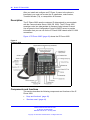
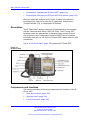
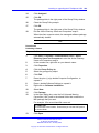
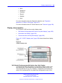
Nortel Communication Server 1000
IP Phones Fundamentals
Release: 6.0
Document Revision: 05.02
www.nortel.com
NN43001-368
.
Nortel Communication Server 1000
Release: 6.0
Publication: NN43001-368
Document release date: 26 May 2009
Copyright © 2003-2009 Nortel Networks. All Rights Reserved.
While the information in this document is believed to be accurate and reliable, except as otherwise expressly
agreed to in writing NORTEL PROVIDES THIS DOCUMENT "AS IS" WITHOUT WARRANTY OR CONDITION OF
ANY KIND, EITHER EXPRESS OR IMPLIED. The information and/or products described in this document are
subject to change without notice.
Nortel, Nortel Networks, the Nortel logo, and the Globemark are trademarks of Nortel Networks.
The Bluetooth word mark and logos are owned by the Bluetooth SIG, Inc. and any use of such marks by Nortel
Networks is under license.
All other trademarks are the property of their respective owners.
.
3
.
Contents
New in this release
Features 19
Other 19
Revision history
Subject 22
19
How to get Help
Getting
Getting
Getting
Getting
help
help
help
help
19
25
from the Nortel Web site 25
over the phone from a Nortel Solutions Center 25
from a specialist by using an Express Routing Code 26
through a Nortel distributor or reseller 26
Nortel IP Phone 2001
Contents 27
Introduction 27
Description 28
Components and functions 28
Keys and functions 28
Services menu 29
Features 30
Display characteristics 31
Cleaning the IP Phone display screen 31
Information line display 31
Soft key label display 32
Package components 32
Installation and configuration 33
Before you begin 34
First-time installation 34
Configuring the IP Phone 2001 34
Connecting the components 35
Startup sequence 37
Redeploying an IP Phone 2001 37
Replacing an IP Phone 2001 38
Removing an IP Phone 2001 from service 38
Nortel Communication Server 1000
IP Phones Fundamentals
NN43001-368 05.02 26 May 2009
Copyright © 2003-2009 Nortel Networks. All Rights Reserved.
27
4
Nortel IP Phone 2002
Contents 41
Introduction 41
Description 42
Components and functions 42
Keys and functions 43
Services menu 44
Features 45
Display characteristics 46
Cleaning the IP Phone display screen 46
Programmable line (DN)/feature key label display
Information line display 47
Soft key label display 47
Package components 47
Installation and configuration 49
Before you begin 50
First-time installation 50
Configuring the IP Phone 2002 50
Connecting the components 51
Startup sequence 53
Redeploying an IP Phone 2002 53
Replacing an IP Phone 2002 54
Removing an IP Phone 2002 from service 54
41
47
Nortel IP Phone 2004
Contents 57
Introduction 57
Description 58
Components and functions 58
Keys and functions 58
Services menu 60
Features 61
Central Answering Position 62
Display characteristics 62
Cleaning the IP Phone display screen 63
Programmable line (DN)/feature key label display
Information line display 63
Soft key label display 63
Package components 64
Installation and configuration 66
Before you begin 66
First-time installation 67
Configuring the IP Phone 2004 67
57
63
Nortel Communication Server 1000
IP Phones Fundamentals
NN43001-368 05.02 26 May 2009
Copyright © 2003-2009 Nortel Networks. All Rights Reserved.
5
Connecting the components 67
Startup sequence 70
Redeploying an IP Phone 2004 70
Replacing an IP Phone 2004 71
Removing an IP Phone 2004 from service
71
IP Phone Key Expansion Module (KEM)
73
Contents 73
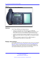
Description 73
Features 74
Display characteristics 74
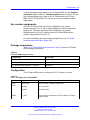
Key number assignments 75
Package components 75
Configuration 75
Installation 78
IP Phone KEM startup initialization 79
Operating parameters 80
General 80
IP Phone 2002 80
IP Phone 2004 81
Virtual Office 81
Firmware 81
Nortel IP Audio Conference Phone 2033
Contents 83
Introduction 83
Description 84
Extension microphones 85
Components and functions 86
Keys and functions 86
Services menu 87
Features 88
Display characteristics 89
Cleaning the IP Phone display screen 89
Information line display 90
Soft key label display 90
Package components 91
Installation and configuration 93
Before you begin 93
First-time installation 94
Configuring the IP Audio Conference Phone 2033 94
Connecting the components 95
Startup sequence 97
Redeploying an IP Audio Conference Phone 2033 97
Replacing an IP Audio Conference Phone 2033 98
Nortel Communication Server 1000
IP Phones Fundamentals
NN43001-368 05.02 26 May 2009
Copyright © 2003-2009 Nortel Networks. All Rights Reserved.
83
6
Removing an IP Audio Conference Phone 2033 from service
Connecting an extension microphone 99
Nortel IP Phone 2007
99
101
Contents 101
Introduction 101
Description 102
Components and functions 102
Keys and functions 103
Services menu 104
Local Tools menu 105
Features 106
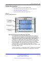
Touch panel 107
Calibrate the touch panel 107
Stylus 107
Dialpad entry 108
Cleaning the IP Phone display screen 109
Display characteristics 109
Application area 110
Tools/Navigation area 112
Package components 112
Installation and configuration 114
Before you begin 114
First-time installation 114
Configuring the IP Phone 2007 114
Connecting the components 115
Startup sequence 117
Redeploying an IP Phone 2007 118
Replacing an IP Phone 2007 119
Removing an IP Phone 2007 from service 119
Nortel IP Phone 1210
Contents 121
Introduction 121
Description 122
Components and functions 123
Keys and functions 123
Services menu 124
Local Tools menu 125
Features 126
Display characteristics 126
Cleaning the IP Phone display screen
Information line display 127
Soft key label display 127
Package components 128
121
127
Nortel Communication Server 1000
IP Phones Fundamentals
NN43001-368 05.02 26 May 2009
Copyright © 2003-2009 Nortel Networks. All Rights Reserved.
7
Installation and configuration 129
Before you begin 129
First-time installation 130
Configuring the IP Phone 1210 130
Connecting the components 131
Startup sequence 133
Redeploying an IP Phone 1210 134
Replacing an IP Phone 1210 135
Removing an IP Phone 1210 from service
135
Nortel IP Phone 1220
Contents 137
Introduction 137
Description 138
Components and functions 139
Keys and functions 139
Services menu 141
Local Tools menu 142
Features 143
Display characteristics 143
Cleaning the IP Phone display screen 144
Programmable line (DN)/feature key label display
Information line display 144
Soft key label display 145
Package components 145
Installation and configuration 147
Before you begin 147
First-time installation 147
Configuring the IP Phone 1220 148
Connecting the components 148
Startup sequence 151
Redeploying an IP Phone 1220 151
Replacing an IP Phone 1220 152
Removing an IP Phone 1220 from service 153
137
144
Nortel IP Phone 1230
Contents 155
Introduction 155
Description 156
Components and functions 157
Keys and functions 157
Services menu 159
Local Tools menu 160
Features 161
Display characteristics 161
Nortel Communication Server 1000
IP Phones Fundamentals
NN43001-368 05.02 26 May 2009
Copyright © 2003-2009 Nortel Networks. All Rights Reserved.
155
8
Cleaning the IP Phone display screen 162
Programmable line (DN)/feature key label display
Information line display 162
Soft key label display 163
Package components 163
Installation and configuration 165
Before you begin 165
First-time installation 165
Configuring the IP Phone 1230 166
Connecting the components 166
Startup sequence 169
Redeploying an IP Phone 1230 169
Replacing an IP Phone 1230 170
Removing an IP Phone 1230 from service 171
162
Nortel IP Phone 1200 Series LCD Expansion Module
173
Contents 173
Description 173
Features 177
Display characteristics 178
Package components 178
Configuration 178
Installation 180
IP Phone 1200 Series LCD Expansion Module startup initialization 181
Operating parameters 182
IP Phone 1220 182
IP Phone 1230 183
Services key operation 185
Display diagnostics 185
Firmware 187
Nortel IP Softphone 2050
Contents 189
Introduction 189
Description 190
Features 190
Additional features 192
Language support 193
Components 193
Call Control window 193
Display characteristics 196
Information display area 197
System Tray 197
USB audio adapters 198
USB Headset Adapter 198
Nortel Communication Server 1000
IP Phones Fundamentals
NN43001-368 05.02 26 May 2009
Copyright © 2003-2009 Nortel Networks. All Rights Reserved.
189
9
Registration 198
GIPS 198
Echo cancellation 200
Clock synchronization 200
Jitter buffer 200
QoS 200
i2050QosSvc.exe 202
DiffSERV (DSCP) 203
802.1p 203
Ethereal traces 203
GXAS 203
Licenses 203
Check out license 204
Cached license 204
Evaluation period 204
License restrictions 204
License types 205
License Server 205
How to configure ports for licensing 206
License Server components 207
Provisioning a License Server 207
Starting the License Server Manager 209
Server Redundancy 210
License file 210
FLEXnet licensing error codes 212
Troubleshooting 212
Key number assignments 221
Minimum system requirements 222
System components 223
Before you begin 224
First-time installation 225
Installing the IP Softphone 2050 for the first time 225
Installing or upgrading the IP Softphone 2050 226
Remote installation 227
Silent installation 232
Upgrading 233
Windows QoS Packet Scheduler 235
Running the IP Softphone 2050 for the first time 236
Redeploying the IP Softphone 2050 236
Removing an IP Softphone 2050 from service 237
Maintenance 237
System data 238
User data 238
Ethernet statistics 239
Nortel Communication Server 1000
IP Phones Fundamentals
NN43001-368 05.02 26 May 2009
Copyright © 2003-2009 Nortel Networks. All Rights Reserved.
10
IP Networking Statistics 240
ICMP Statistics 241
Audio Connection Data 241
USB Headset Data 243
Telchemy VQMon 243
PC System Information 244
Personal Call Recording Data 245
Duplicate Media Stream Call Recording Data 245
Licensing Data 245
Expansion Module for IP Softphone 2050
Contents 247
Description 247
Features 248
Display characteristics
Configuration 249
Installation 250
Operation 250
247
248
Nortel WLAN Handset 2210, WLAN Handset 2211, WLAN
Handset 2212, WLAN Handset 6120, and WLAN Handset
6140
251
Nortel Mobile Voice Client 2050
253
Contents 253
Introduction 253
Description 254
System requirements 254
Supported features 254
Application software 255
ClearType 256
MVC 2050 components 256
Compatible PDAs 256
Headsets 256
Automatic Gain Control and feedback 256
Audio quality 257
MVC 2050 Call Handling screen 257
Display 257
Dialpad 257
Soft keys (self-labeled) 257
Programmable line/feature keys 258
Menus 258
MVC 2050 graphical interface (skins) components
Icons 261
Operation 263
260
Nortel Communication Server 1000
IP Phones Fundamentals
NN43001-368 05.02 26 May 2009
Copyright © 2003-2009 Nortel Networks. All Rights Reserved.
11
MVC 2050 installation 264
MVC 2050 installation method 264
MVC 2050 removal 265
Configuration 266
Settings 266
802.1p and DiffServ 273
Global Packet Loss Concealment algorithm 273
MVC 2050 and WLAN 273
802.11b wireless ethernet networking 273
Wireless Fidelity 274
Roaming and handover 274
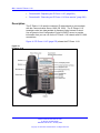
Nortel IP Phone 1110
275
Contents 275
Introduction 275
Description 276
Components and functions 277
Keys and functions 277
Services menu 278
Local Tools menu 279
Features 279
Display characteristics 280
Context-sensitive soft key label display 280
Information line display 281
Cleaning the IP Phone display screen 281
Package components 281
Installation and configuration 283
Before you begin 283
First-time installation 283
Configuring the IP Phone 1110 284
Connecting the components 284
Startup sequence 289
TFTP firmware upgrade 290
Redeploying an IP Phone 1110 290
Replacing an IP Phone 1110 291
Removing an IP Phone 1110 from service 291
Nortel IP Phone 1120E
Contents 293
Introduction 293
Description 294
Components and functions 294
Keys and functions 295
Services menu 296
Local Tools menu 297
Nortel Communication Server 1000
IP Phones Fundamentals
NN43001-368 05.02 26 May 2009
Copyright © 2003-2009 Nortel Networks. All Rights Reserved.
293
12
Features 298
Display characteristics 299
Self-labeled line/programmable feature key label display
Information line display 300
Context-sensitive soft key label display 300
Cleaning the IP Phone display screen 301
Package components 301
Installation and configuration 302
Before you begin 303
First-time installation 303
Configuring the IP Phone 1120E 303
Connecting the components 304
Startup sequence 308
TFTP firmware upgrade 309
Redeploying an IP Phone 1120E 309
Replacing an IP Phone 1120E 310
Removing an IP Phone 1120E from service 310
299
Nortel IP Phone 1140E
Contents 313
Introduction 313
Description 314
Components and functions 315
Keys and functions 315
Services menu 317
Local Tools menu 318
Features 318
Display characteristics 319
Self-labeled line/programmable feature key label display
Information line display 320
Context-sensitive soft key label display 321
Cleaning the IP Phone display screen 321
Package components 321
Installation and configuration 323
Before you begin 323
First-time installation 323
Configuring the IP Phone 1140E 323
Connecting the components 324
Startup sequence 329
TFTP firmware upgrade 329
Bluetooth wireless technology 329
Redeploying an IP Phone 1140E 329
Replacing an IP Phone 1140E 330
Removing an IP Phone 1140E from service 331
Nortel Communication Server 1000
IP Phones Fundamentals
NN43001-368 05.02 26 May 2009
Copyright © 2003-2009 Nortel Networks. All Rights Reserved.
313
320
13
Nortel IP Phone 1150E
333
Contents 333
Introduction 333
Description 334
Components and functions 336
Services menu 339
Local Tools menu 340
Features 341
Display characteristics 343
Self-labeled line/programmable feature key label 343
Information line display 344
Context-sensitive soft key label 344
Cleaning the IP Phone display screen 344
Headset support 344
Package components 345
Installation and configuration 346
Before you begin 347
First-time installation 347
Configuring the IP Phone 1150E 347
Connecting the components 348
Startup sequence 353
TFTP firmware upgrade 353
Bluetooth wireless technology 353
Redeploying an IP Phone 1150E 354
Replacing an IP Phone 1150E 355
Removing an IP Phone 1150E from service 355
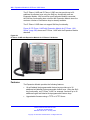
Expansion Module for IP Phone 1100 Series
Contents 357
Description 357
Features 358
Display characteristics 359
Package components 359
Configuration 359
Installation 360
Expansion Module startup initialization 364
Operating parameters 365
IP Phone 1120E 365
IP Phone 1140E and IP Phone 1150E 365
Services key operation 366
Display diagnostics 367
Firmware 368
Nortel Communication Server 1000
IP Phones Fundamentals
NN43001-368 05.02 26 May 2009
Copyright © 2003-2009 Nortel Networks. All Rights Reserved.
357
14
Features
369
Contents 369
Telephony features 369
Corporate Directory 370
Personal Directory 370
Redial List 370
Callers List 370
Password Administration 371
IP Call Recording 371
Virtual Office 371
Emergency Services for Virtual Office 371
Active Call Failover 371
Enhanced UNIStim Firmware download 372
Media security 373
Live Dialpad 377
Normal Mode Indication 378
Caller ID display order 378
Languages 378
Key number assignments 380
Network features 382
Full Duplex 382
802.1x Port-based network access control 387
802.1ab Link Layer Discovery Protocol 404
Dynamic Host Configuration Protocol 405
Regulatory and safety information
Warnings: 431
Other compliancies 433
For those devices equipped with Bluetooth wireless technology
DenAn regulatory notice for Japan 434
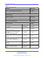
Specifications
431
433
435
Contents 435
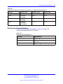
IP Phone power requirements 435
Environmental specifications 437
802.1Q VLAN description
Contents 439
Introduction 439
Description 440
IP Phone support 441
IP Softphone 2050 support 441
Three-port switch support 441
VLAN IDs 442
Nortel Communication Server 1000
IP Phones Fundamentals
NN43001-368 05.02 26 May 2009
Copyright © 2003-2009 Nortel Networks. All Rights Reserved.
439
15
Automatic VOICE VLAN ID configuration 443
Enhanced VLAN Tagging 444
Enhanced DATA VLAN 444
Provisioning the IP Phones
Contents 447
Introduction 447
Description 448
Manual provisioning 448
Automatic provisioning 449
Configuration 450
Operation 474
Precedence rule and stickiness control
IP Phone reset 475
Factory default 475
447
474
Manual provisioning of IP Phone 1110 and 1200 Series
Contents 479
Introduction 479
Provisioning parameters
479
Manual provisioning of IP Phone 2007 and 1100 Series
Contents 487
Introduction 487
Provision parameters
479
487
487
Manual provisioning of IP Phone 2000 Series
Contents 495
Introduction 495
Provision parameters 495
Provisioning the Phase II IP Phones 496
Provisioning the IP Audio Conference Phone 2033
495
501
Dynamic Host Configuration Protocol server configuration
505
Install a Windows NT 4 or Windows 2000 server 505
Configure a Windows NT 4 server with DHCP 505
Configure a Windows 2000 server with DHCP 508
Install ISC DHCP Server 511
Configure ISC DHCP Server 512
Configure ISC DHCP to work with the IP Phones 512
Install and configure a Solaris 2 server 515
Gratuitous Address Resolution Protocol Protection
519
Local Tools menu
521
Contents 521
Introduction 521
Nortel Communication Server 1000
IP Phones Fundamentals
NN43001-368 05.02 26 May 2009
Copyright © 2003-2009 Nortel Networks. All Rights Reserved.
16
Local Tools menu password protection 521
Controlling the menu lock for IP Phone 2007 522
Configuring Secure Local Menu using Network provisioning 523
Accessing the Local Tools menu 523
Local Tools options 524
Local Tools menu for IP Phone 1120E, IP Phone 1140E, and IP Phone
1150E 524
Local Tools menu for IP Phone 1110, IP Phone 1210, IP Phone 1220, and IP
Phone 1230 528
IP Phone diagnostic utilities
531
Contents 531
Introduction 531
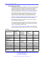
Text-based diagnostic utilities 531
Network diagnostic utilities 532
Accessing Network Diagnostic utilities from the IP Phone 534
Network Diagnostic Utilities data display pages 546
Network Address Translation Traversal 557
General Information 557
Using CLI Commands 559
Graphic-based diagnostics utilities 562
Local Diagnostics 568
Bluetooth and Wireless Fidelity interference
579
Headset support
581
Introduction 581
Wired headsets 581
Bluetooth wireless technology
Universal Serial Bus audio 588
USB wireless headsets 589
MHA 589
ATA 589
Configure the headsets 589
Active Headset Device 589
Enable HID Commands 589
Headset Type 590
Activate USB Audio 590
581
Language enhancement
Contents 591
Description 591
UTF-8 character encoding 591
TFTP Server support 592
Synchronizing the language 592
Expansion Module for IP Phone 1100 Series font support
Nortel Communication Server 1000
IP Phones Fundamentals
NN43001-368 05.02 26 May 2009
Copyright © 2003-2009 Nortel Networks. All Rights Reserved.
591
592
17
TFTP Server
593
Contents 593
Introduction 593
TFTP Server planning 593
Pre-download checklist 594
Updating IP Phones firmware 595
Updating the firmware 596
Expansion Module for IP Phones 600
Downloading and configuring fonts 601
IP Phone context-sensitive soft keys
605
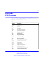
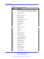
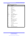
Call features
607
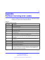
FLEXnet licensing error codes
611
Nortel Communication Server 1000
IP Phones Fundamentals
NN43001-368 05.02 26 May 2009
Copyright © 2003-2009 Nortel Networks. All Rights Reserved.
18
Nortel Communication Server 1000
IP Phones Fundamentals
NN43001-368 05.02 26 May 2009
Copyright © 2003-2009 Nortel Networks. All Rights Reserved.
19
.
New in this release
The following sections detail what’s new in IP Phones Fundamentals
(NN43001-368) for Nortel Communication Server 1000 (CS 1000) Release
6.0.
Features
Communication Server Release 6.0 includes the following additions:
•
•
Two-line mode for IP Phones 1110 and 1210
•
New telephony features: Caller ID display order and Normal Mode
Indication (with configurable Normal Mode Display)
Dynamic IP Line localization with support of 25 languages. Dynamic
localization means that prompt translations can be easily updated
and new translations can be added. New translations are regionally
controlled.
Other
Revision history
May 2009
Standard 05.02. This document is up-issued to support
CS 1000 Release 6.0.
May 2009
Standard 05.01. This document is up-issued to support
CS 1000 Release 6.0.
August 2008
Standard 04.03. This document is up-issued to support
UNIStim Release 3.0 for CS 1000 Release 5.5.
August 2008
Standard 04.02. This document is up-issued to support an
update to technical content for the IP Softphone 2050.
July 2008
Standard 04.01. This document is up-issued to support IP
Softphone 2050 Release 3.1 for Communication Server
1000 Release 5.5. This document also contains updates
to technical content for UNIStim 3.0.
Nortel Communication Server 1000
IP Phones Fundamentals
NN43001-368 05.02 26 May 2009
Copyright © 2003-2009 Nortel Networks. All Rights Reserved.
20 New in this release
May 2008
Standard 03.07. This document is up-issued to support
Communication Server 1000 Release 5.5. This document
contains an update to technical content within the IP
Phone 1200 Series sections.
April 2008
Standard 03.06. This document is up-issued to support
Communication Server 1000 Release 5.5. This document
contains support for UNIStim 3.0.
April 2008
Standard 03.05. This document is up-issued to support
Communication Server 1000 Release 5.5. This document
contains an update to technical content.
March 2008
Standard 03.04. This document is up-issued to support
Communication Server 1000 Release 5.5. This document
contains an update to technical content for IP Softphone
2050 Release 3 and an update to technical content for
TFTP server firmware download.
February 2008
Standard 03.03. This document is up-issued to support
Communication Server 1000 Release 5.5. This document
contains updates to technical content.
December 2007
Standard 03.02. This document is up-issued to support
Communication Server 1000 Release 5.5. This document
contains updates to technical content.
December 2007
Standard 03.01. This document is up-issued to support
Communication Server 1000 Release 5.5.
December 2007
Standard 02.01. This document is up-issued to support
Communication Server 1000 Release 5.0. This document
contains support for IP Softphone 2050 Release 3.
June 2007
Standard 01.02. This document is up-issued to support
Communication Server 1000 Release 5.0.
May 2007
Standard 01.01. This document is up-issued to support
Communication Server 1000 Release 5.0. This document
is renamed IP Phones Fundamentals (NN43001-368) and
contains information previously contained in the following
legacy document, now retired: (553-3001-368).
March 2007
Standard 23.00. This document is up-issued to support
Communication Server 1000 Release 4.5. This document
is up-issued to include updated information for Mobile
Voice Client (MVC) 2050.
March 2007
Standard 22.00. This document is up-issued to support
Communication Server 1000 Release 4.5. This document
is up-issued to support the addition of the IP Phone 1110.
January 2007
Standard 21.00. Not issued.
Nortel Communication Server 1000
IP Phones Fundamentals
NN43001-368 05.02 26 May 2009
Copyright © 2003-2009 Nortel Networks. All Rights Reserved.
Other
21
November 2006
Standard 20.00. This document is up-issued to support
CS 1000 Release 4.5. This document is up-issued to
support the addition of the Expansion Module for IP
Phone 1100 Series.
October 2006
Standard 19.00. This document is up-issued to support
Communication Server 1000 Release 4.5.
October 2006
Standard 18.00. This document is up-issued to support
CS 1000 Release 4.5. This document is up-issued to
support the addition of the IP Phone 1150E.
August 2006
Standard 17.00. This document is up-issued to support
CS 1000 Release 4.5.
July 2006
Standard 16.00. This document is up-issued to support
CS 1000 Release 4.5.
June 2006
Standard 15.00. This document is up-issued to include
UNIStim firmware up-version.
April 2006
Standard 14.00. This document is up-issued to support
CS 1000 Release 4.5. This document is up-issued to
include content for the IP Audio Conference Phone 2033
Release 2.
April 2006
Standard 13.00. Not issued.
March 2006
Standard 12.00. This document is up-issued to support
CS 1000 Release 4.5. This document is up-issued to
include updated content for the IP Softphone 2050 V2.
January 2006
Standard 11.00. This document is up-issued to support
CS 1000 Release 4.5. This document is up-issued to
include updated content for the IP Phone 1120E and IP
Phone 1140E.
January 2006
Standard 10.00. This document is up-issued to support
CS 1000 Release 4.5. This document is up-issued to
include updated content for the IP Phone 1140E.
January 2006
Standard 9.00. This document is up-issued to support CS
1000 Release 4.5.
November 2005
Standard 8.00. This document is up-issued to support the
addition of IP Phone 1140E.
August 2005
Standard 7.00. This document is up-issued to support CS
1000 Release 4.5.
April 2005
Standard 6.00. This document is up-issued to support the
addition of the IP Phone 2007.
April 2005
Standard 5.00. This document is up-issued to support the
addition of the IP Audio Conference Phone 2033.
Nortel Communication Server 1000
IP Phones Fundamentals
NN43001-368 05.02 26 May 2009
Copyright © 2003-2009 Nortel Networks. All Rights Reserved.
22 New in this release
February 2005
Standard 4.00. This document is up-issued to support the
8.x Firmware Upgrade for IP Phones.
September 2004
Standard 3.00. This document is up-issued to support
Communication Server 1000 Release 4.0.
June 2004
Standard 2.00. This document is up-issued to include the
Nortel Networks Mobile Voice Client 2050.
October 2003
Standard 1.00. This document is a new NTP for
Succession 3.0 Software. It was created to support
a restructuring of the Documentation Library. This
document contains information previously contained in the
following legacy document, now retired: Internet Terminals
Description (553-3001-217).
Subject
This document contains description, installation, and administration
information for the following:
•
•
Nortel IP Audio Conference Phone 2033
•
•
•
•
•
•
•
•
•
•
•
•
Nortel IP Phone Key Expansion Module (KEM)
Nortel IP Phone 2001, IP Phone 2002, IP Phone 2004, and IP Phone
2007
Nortel IP Softphone 2050
Nortel Mobile Voice Client 2050 for Personal Digital Assistants (PDA)
Nortel IP Phone 1120E
Nortel IP Phone 1140E
Nortel IP Phone 1150E
Nortel IP Phone 1110
Expansion Module for IP Phone 1100 Series
Nortel IP Phone 1210
Nortel IP Phone 1220
Nortel IP Phone 1230
Nortel IP Phone 1200 Series Expansion Module (EM)
Nortel Communication Server 1000
IP Phones Fundamentals
NN43001-368 05.02 26 May 2009
Copyright © 2003-2009 Nortel Networks. All Rights Reserved.
Subject
23
Note on legacy products and releases
This NTP contains information about systems, components, and features
that are compatible with Nortel Communication Server 1000 Release 6.0
software. For more information about legacy products and releases, click
the Technical Documentation link under Support on the Nortel home
page:
www.nortel.com
NTPs
This document references the following:
•
•
•
•
•
•
•
•
•
•
•
•
•
IP Phone 2001 User Guide (NN43115-102)
•
•
•
•
•
•
•
•
•
•
IP Phone 1210 User Guide (NN43140-101)
IP Phone 2002 User Guide (NN43116-104)
IP Phone 2004 User Guide (NN43117-102)
IP Phone 2007 User Guide (NN43118-100)
IP Phone Audio Conference Phone 2033 User Guide ((NN43111-100))
IP Phone 1120E User Guide (NN43112-103)
IP Phone 1140E User Guide (NN43113-106)
IP Phone 1150E User Guide (NN43114-100)
IP Phone 1110 User Guide (NN43110-101)
IP Softphone 2050 User Guide (NN43119-101)
Mobile Voice Client 2050 User Guide (NN43119-103)
IP Phone Key Expansion Module User Guide (NN43119-102)
Expansion Module for IP Phones 1100 Series User Guide
(NN43130-101)
IP Phone 1220 User Guide (NN43141-101)
IP Phone 1230 User Guide (NN43142-101)
WLAN IP Telephony Installation and Commissioning (NN43001-504)
Converging the Data Network with VoIP Fundamentals (NN43001-260)
Signaling Server IP Line Applications Fundamentals (NN43001-125)
IP Peer Networking Installation and Commissioning (NN43001-313)
Security Management Fundamentals (NN43001-604)
Features and Services Fundamentals (NN43001-106)
Central Answering Position Implementation Guide (NN43011-501)
Nortel Communication Server 1000
IP Phones Fundamentals
NN43001-368 05.02 26 May 2009
Copyright © 2003-2009 Nortel Networks. All Rights Reserved.
24 New in this release
•
•
•
•
Software Input Output Reference - Administration (NN43001-611)
•
•
•
•
•
•
•
IP Phone 1110 Getting Started Card (NN43100-300)
Secure Multimedia Controller Implementation Guide (NN43001-325)
Element Manager System Reference - Administration (NN43001-632)
Nortel Application Gateway 1000/2000 Administration Guide
(NN42360-600)
IP Phone 1120E Getting Started Card (NN43112-100)
IP Phone 1140E Getting Started Card (NN43113-103)
IP Phone 1150E Getting Started Card (NN43114-103)
Automatic Call Distribution Fundamentals (NN43001-551)
Emergency Service Access Fundamentals (NN43001-613)
Software Input Output Reference - Maintenance (NN43001-711)
Online
To access Nortel documentation online, click the Technical
Documentation link under Support on the Nortel home page:
www.nortel.com
CD-ROM
To obtain Nortel documentation on CD-ROM, contact your Nortel customer
representative.
Nortel Communication Server 1000
IP Phones Fundamentals
NN43001-368 05.02 26 May 2009
Copyright © 2003-2009 Nortel Networks. All Rights Reserved.
25
.
How to get Help
This chapter explains how to get help for Nortel products and services.
Getting help from the Nortel Web site
The best way to get technical support for Nortel products is from the Nortel
Technical Support Web site:
www.nortel.com/support
This site provides quick access to software, documentation, bulletins, and
tools to address issues with Nortel products. From this site, you can:
•
•
download software, documentation, and product bulletins
•
sign up for automatic notification of new software and documentation
for Nortel equipment
•
open and manage technical support cases
search the Technical Support Web site and the Nortel Knowledge Base
for answers to technical issues
Getting help over the phone from a Nortel Solutions Center
If you do not find the information you require on the Nortel Technical
Support Web site, and you have a Nortel support contract, you can also
get help over the telephone from a Nortel Solutions Center.
In North America, call 1-800-4NORTEL (1-800-466-7835).
Outside North America, go to the following Web site to obtain the
telephone number for your region:
www.nortel.com/callus
Nortel Communication Server 1000
IP Phones Fundamentals
NN43001-368 05.02 26 May 2009
Copyright © 2003-2009 Nortel Networks. All Rights Reserved.
26 How to get Help
Getting help from a specialist by using an Express Routing Code
To access some Nortel Technical Solutions Centers, you can use an
Express Routing Code (ERC) to quickly route your call to a specialist in
your Nortel product or service. To locate the ERC for your product or
service, go to:
www.nortel.com/erc
Getting help through a Nortel distributor or reseller
If you purchased a service contract for your Nortel product from a
distributor or authorized reseller, contact the technical support staff for that
distributor or reseller.
Nortel Communication Server 1000
IP Phones Fundamentals
NN43001-368 05.02 26 May 2009
Copyright © 2003-2009 Nortel Networks. All Rights Reserved.
27
.
Nortel IP Phone 2001
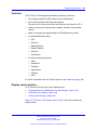
Contents
This section contains the following topics:
•
•
•
•
•
•
•
•
•
•
“Introduction” (page 27)
“Description” (page 28)
“Components and functions” (page 28)
“Features” (page 30)
“Display characteristics” (page 31)
“Package components” (page 32)
“Installation and configuration” (page 33)
“Redeploying an IP Phone 2001” (page 37)
“Replacing an IP Phone 2001” (page 38)
“Removing an IP Phone 2001 from service” (page 38)
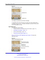
Introduction
This section explains how to install and maintain the IP Phone 2001. For
information about using the IP Phone 2001, see the IP Phone 2001 User
Guide (NN43115-102).
This section contains the following procedures:
•
•
•
Procedure 1 “Configuring the IP Phone 2001” (page 34)
•
•
Procedure 4 “Replacing an IP Phone 2001” (page 38)
Procedure 2 “Connecting the components” (page 35)
Procedure 3 “Changing the TN of an existing IP Phone 2001” (page
37)
Procedure 5 “Removing an IP Phone 2001 from service” (page 38)
Nortel Communication Server 1000
IP Phones Fundamentals
NN43001-368 05.02 26 May 2009
Copyright © 2003-2009 Nortel Networks. All Rights Reserved.
28 Nortel IP Phone 2001
After you install and configure an IP Phone, if power to the phone is
interrupted, you need not re-enter the IP parameters, node number,
Terminal Number (TN), or reacquisition of firmware.
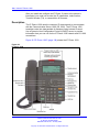
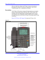
Description
The IP Phone 2001 uses the customer IP data network to communicate
with the Communication Server 1000 (CS 1000). The IP Phone 2001
translates voice into data packets for transport using Internet Protocol.
Use a Dynamic Host Configuration Protocol (DHCP) server to provide
information that you can use for the IP Phone 2001 network and CS 1000
connections.
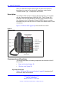
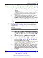
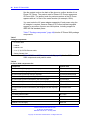
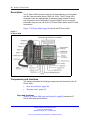
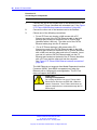
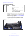
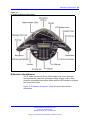
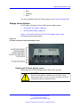
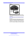
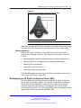
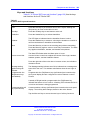
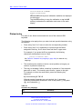
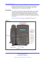
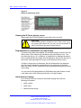
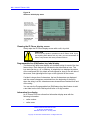
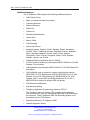
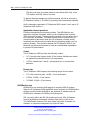
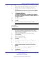
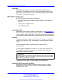
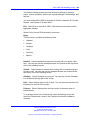
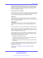
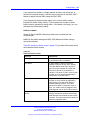
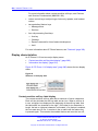
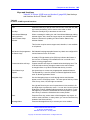
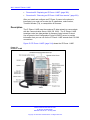
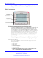
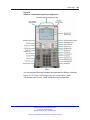
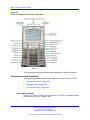
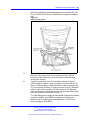
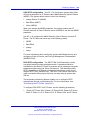
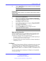
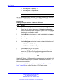
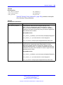
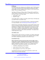
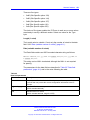
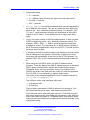
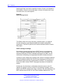
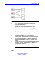
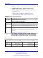
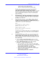
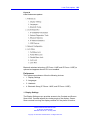
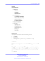
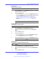
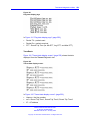
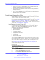
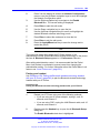
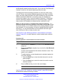
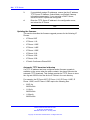
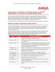
Figure 1 "IP Phone 2001" (page 28) shows the IP Phone 2001.
Figure 1
IP Phone 2001
Components and functions
This section describes the following components and functions of the IP
Phone 2001:
•
•
“Keys and functions” (page 28)
“Services menu” (page 29)
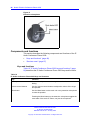
Keys and functions
Table 1 "IP Phone 2001 keys and functions" (page 29) describes the IP
Phone 2001 keys and functions.
Nortel Communication Server 1000
IP Phones Fundamentals
NN43001-368 05.02 26 May 2009
Copyright © 2003-2009 Nortel Networks. All Rights Reserved.
Components and functions
29
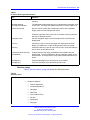
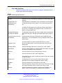
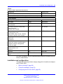
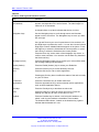
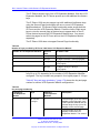
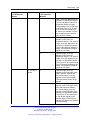
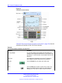
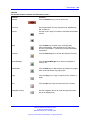
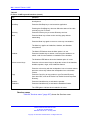
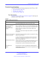
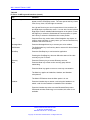
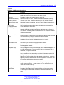
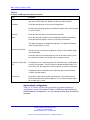
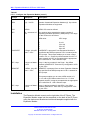
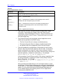
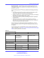
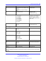
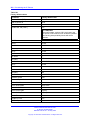
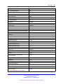
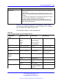
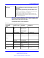
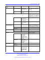
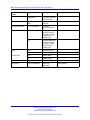
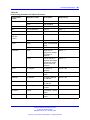
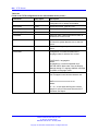
Table 1
IP Phone 2001 keys and functions
Key
Function
Speaker
Press the Line key to activate the speaker for on-hook dialing and
listening.
Message waiting/
Incoming call indicator
The Message waiting lamp turns on to indicate that a message is left
for the user. This lamp also flashes when the IP Phone ringer is on.
Volume control bar
Use the volume control bar to adjust the volume of the Handset,
Ringer, and On-hook Dialing/Listen tones.
Press the right side of the rocker bar to increase volume; press the
left side to decrease volume.
Navigation keys
Use the navigation keys to scroll through menus and lists in the
display area.
Line key
Use the Line key to access the single line and activate on-hook
dialing. No status icon or light emitting diode (LED) is provided.
Hold key
Press the Hold key to put an active call on hold. Press the Dial/Line
key to return to the caller on hold.
Context-sensitive soft keys
(self-labeled)
Context-sensitive soft keys (self-labeled) are located below the
display area. The LCD label above the key changes, based on the
active feature. A triangle before a key label indicates that the key is
active.
Message key
Press the Message key to access your voice mailbox.
Goodbye key
Press the Goodbye key to terminate an active call.
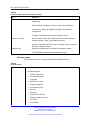
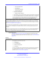
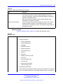
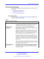
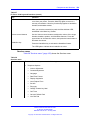
Services menu
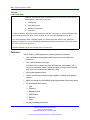
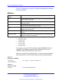
Table 2 "Services menu" (page 29) shows the Services menu.
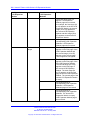
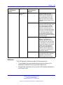
Table 2
Services menu
Services key
Press the Services key to access the following items:
•
Telephone Options
— Volume adjustment
— Contrast adjustment
— Language
— Date/Time
— Local DialPad Tone
— Set Info
— Diagnostics
— Ring type
Nortel Communication Server 1000
IP Phones Fundamentals
NN43001-368 05.02 26 May 2009
Copyright © 2003-2009 Nortel Networks. All Rights Reserved.
30 Nortel IP Phone 2001
— Call Timer
— Live Dialpad
— Normal Mode indication
— Caller ID display order
•
Password Admin
— Station Control Password
•
•
Virtual Office Login and Virtual Office Logout (if Virtual Office is configured)
Test Local Mode and Resume Local Mode (if Branch Office is configured)
Press the Services key to exit from any menu or menu item.
You can customize the IP Phone features to meet user requirements. For
more information, see the IP Phone 2001 User Guide (NN43115-102).
Double-press the Services key to access Network diagnostic utilities. For
more information about Network diagnostic utilities, see “IP Phone diagnostic
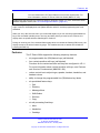
utilities” (page 531).
If an incoming call is presented while you configure information in the Services menu, the phone
rings. However, the display does not update with the caller ID, and the programming text is not
disturbed.
While you are in the Services menu you cannot dial digits but you can use the programmable line
keys, such as Redial (double-press a line key) and Auto dial key to make a call. However, the
display does not update with the dialed digits or Caller ID.
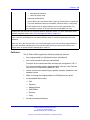
Features
The IP Phone 2001 supports the following telephony features:
•
four context-sensitive soft keys
Functions for the context-sensitive soft keys are configured in LD 11.
For more information about context-sensitive soft keys, see Features
and Services Fundamentals (NN43001-106).
•
•
volume control bar to adjust ringer, speaker, handset volume
two specialized feature keys
— Message/Inbox
— Services
•
two call-processing keys
— Goodbye
— Hold
Nortel Communication Server 1000
IP Phones Fundamentals
NN43001-368 05.02 26 May 2009
Copyright © 2003-2009 Nortel Networks. All Rights Reserved.
Display characteristics
31
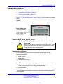
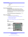
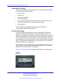
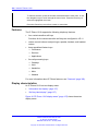
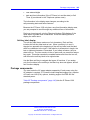
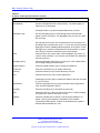
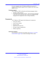
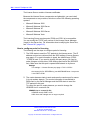
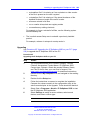
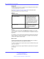
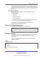
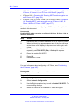
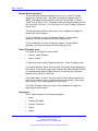
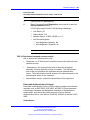
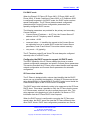
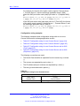
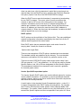
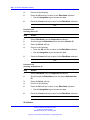
Display characteristics
An IP Phone 2001 has two display areas:
•
•
“Information line display” (page 31)
“Soft key label display” (page 32)
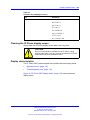
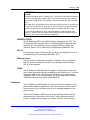
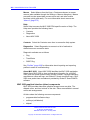
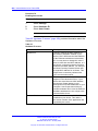
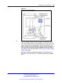
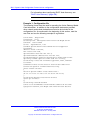
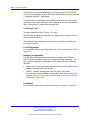
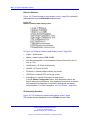
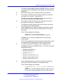
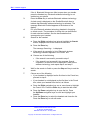
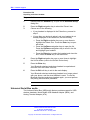
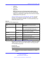
Figure 2 "IP Phone 2001 display areas" (page 31) shows these two display
areas.
Figure 2
IP Phone 2001 display areas
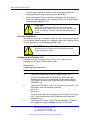
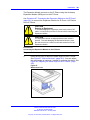
Cleaning the IP Phone display screen
Gently wipe the IP Phone display screen with a soft, dry cloth.
CAUTION
Do not use any liquids or powders on the IP Phone 2001. Using
anything other than a soft, dry cloth can contaminate IP Phone
components and cause premature failure.
Information line display
An IP Phone 2001 has a one-line information display area with the
following information:
•
•
•
•
•
caller number
•
set information
caller name
feature prompt strings
user-entered digits
date and time information (if the IP Phone is in an idle state) or Call
Timer (if provisioned in the Telephone options menu)
The information area changes according to the call-processing state and
active features.
Nortel Communication Server 1000
IP Phones Fundamentals
NN43001-368 05.02 26 May 2009
Copyright © 2003-2009 Nortel Networks. All Rights Reserved.
32 Nortel IP Phone 2001
Soft key label display
The soft key label has a maximum six characters. Each soft key includes
the soft key label and an icon. When a soft key is in use, a triangle icon
appears at the beginning of the soft key label, and the label shifts one
character to the right. (If the label is six characters in length, the last or
rightmost character is truncated.) If a feature is enabled, the icon state
turns to On. The icon remains in the on state until the feature key is
pressed again. This cancels the enabled feature and turns the icon off,
and returns the soft key label to its original state.
Use the More soft key to navigate the layers of functions. If only four
functions are assigned to the soft keys, the More key does not appear,
and all four functions are displayed.
Package components
The following information applies to Phase II IP Phones. Product codes for
Phase II IP Phones are different from previous IP Phones.
See the product code on the back of the phone to confirm whether it is a
Phase II IP Phone. The product code for Phase II IP Phones appears as
IP Phone 200x. The product code for previous versions of the IP Phones
appears with an i in front of the model number (for example, i200x).
You must order the AC power adapter separately if local power using the
AC adapter is required, because Phase II IP Phones include integrated
support for a number of power over LAN options, including support for
IEEE 802.3af standard power.
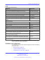
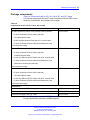
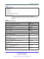
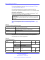
Table 3 "Package components" (page 32) lists the IP Phone 2001 package
components.
Table 3
Package components
•
•
•
•
•
IP Phone 2001
handset
handset cord
2.1 m (7-ft) e Ethernet cable
Getting Started Card
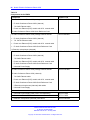
Table 4 "IP Phone 2001 components list" (page 33) lists the IP Phone
2001 components and product codes.
Nortel Communication Server 1000
IP Phones Fundamentals
NN43001-368 05.02 26 May 2009
Copyright © 2003-2009 Nortel Networks. All Rights Reserved.
Installation and configuration
33
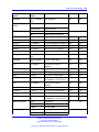
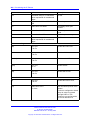
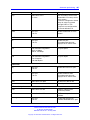
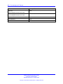
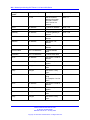
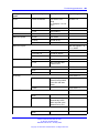
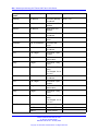
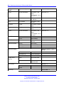
Table 4
IP Phone 2001 components list
Component
Product code
IP Phone 2001 (Ethergray) with Icon keycaps
NTDU90AA16/A0533387
IP Phone 2001 (Ethergray) with English text label keycaps
NTDU90BA16/A0533388
IP Phone 2001 (Charcoal) with Icon keycaps
NTDU90AA70/A0053389
IP Phone 2001 (Charcoal) with English text label keycaps
NTDU90BA70/A0533390
IP Phone 2001 (Charcoal with Bezel) with Icon keycaps
NTDU90AB70
IP Phone 2001 (Charcoal with Bezel) with Icon keycaps (RoHS)
NTDU90AC70E6
IP Phone 2001 (Charcoal with Bezel) with English text label keycaps
NTDU90BB70
IP Phone 2001 (Charcoal with Bezel) with English text label keycaps
(RoHS)
NTDU90BC70E6
Replacement parts
7-ft. Cat5e Ethernet Cable
N0177422
Handset, Ethergray
A0788874
Handset, Charcoal
A0758634
Handset cord, Ethergray; for IP Phone 2004 and IP Phone 2001
A088682
Handset cord, Charcoal; for IP Phone 2004 and IP Phone 2001
N0000764
IP Phone 2001 Power Adapters
Power transformer (117/120 VAC 50/60 Hz) (North America)
A0619627
Power transformer 3-prong AC to AC, direct plug-in, 8 W, 240 VAC,
50 Hz to 16 VAC at 500 mA (Ireland and UK)
A0656598
Power transformer AC to AC, direct plug-in, 8 W, 230 VAC, 50/60
Hz, to 16 VAC at 500 mA (Europe)
A0619635
Power transformer 2-prong wall plug direct plug-in AC to AC, 8 W,
240 VAC, 50 Hz, to 16 VAC at 500 mA (Australia and New Zealand)
A0647042
Power transformer AC to AC, direct plug-in, 8 W, 100 VAC, 50 Hz,
to 16 VAC at 500 mA
A0828858
For more information, and for information about previous versions of the IP
Phone, contact your Nortel representative.
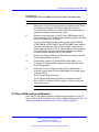
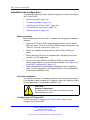
Installation and configuration
The following sections provide a step-by-step guide to install and configure
the IP Phone 2001:
•
•
•
“Before you begin” (page 34)
“First-time installation” (page 34)
“Configuring the IP Phone 2001” (page 34)
Nortel Communication Server 1000
IP Phones Fundamentals
NN43001-368 05.02 26 May 2009
Copyright © 2003-2009 Nortel Networks. All Rights Reserved.
34 Nortel IP Phone 2001
•
•
“Connecting the components” (page 35)
“Startup sequence” (page 37)
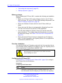
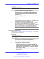
Before you begin
Before installing the IP Phone 2001, complete the following pre-installation
checklist:
•
Ensure one IP Phone 2001 boxed package exists for each IP Phone
2001 you install. For a list of IP Phone 2001 package components, see
Table 3 "Package components" (page 32).
•
Ensure one Software License exists for each IP Phone 2001 you
install.
•
Ensure the host Call Server is equipped with a Signaling Server that
runs the Line Terminal Proxy Server (LTPS) application.
•
If an AC power adapter is required, ensure you use the correct AC
power transformer. The voltage rating of the transformer must match
the wall outlet voltage. See Table 4 "IP Phone 2001 components list"
(page 33).
•
Ensure the latest IP Phone firmware is deployed to the IP telephony
node. For more information, see Signaling Server IP Line Applications
Fundamentals (NN43001-125).
First-time installation
You must first install an IP telephony node with the Communication Server.
For information about installing an IP telephony node, see Signaling Server
IP Line Applications Fundamentals (NN43001-125).
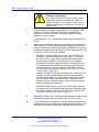
CAUTION
Do not plug your IP Phone 2001 into an ISDN connection.
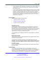
Severe damage can result.
Configuring the IP Phone 2001
Use Procedure 1 “Configuring the IP Phone 2001” (page 34) to configure
the IP Phone 2001 for the first time.
Procedure 1
Configuring the IP Phone 2001
Step
Action
1
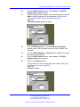
Configure a virtual loop on the Call Server using LD 97. For
more information about configuring a virtual loop, see Signaling
Nortel Communication Server 1000
IP Phones Fundamentals
NN43001-368 05.02 26 May 2009
Copyright © 2003-2009 Nortel Networks. All Rights Reserved.
Installation and configuration
35
Server IP Line Applications Fundamentals (NN43001-125) and
Software Input Output Reference-Administration (NN43001-611).
2
Configure the IP Phone 2001 on the Call Server using LD 11. At
the prompt, enter the following:
REQ:new
TYPE:2001P2
For more information about configuring the IP Phone 2001 using
LD 11, see Software Input Output Reference-Administration
(NN43001-611).
3
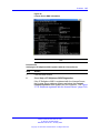
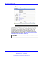
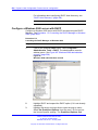
Configure the IP Phone 2001 in Element Manager. IP Phones
are configured using the Phones section in the Element
Manager navigation tree. For more information about configuring
the IP Phone 2001 using Element Manager, see Element
Manager System Reference - Administration (NN43001-632).
--End--
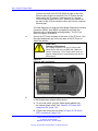
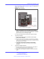
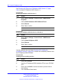
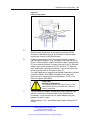
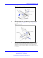
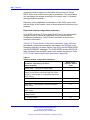
Connecting the components
Use “Connecting the components” (page 35) to connect the IP Phone
2001 components.
Procedure 2
Connecting the components
Step
Action
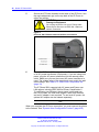
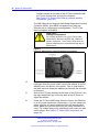
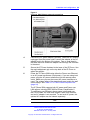
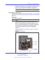
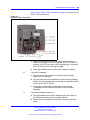
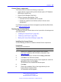
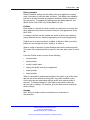
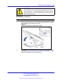
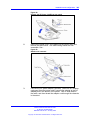
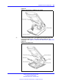
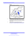
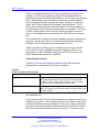
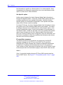
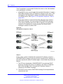
1
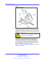
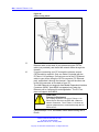
Connect one end of the handset cord to the handset jack on the
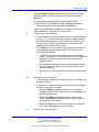
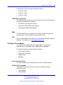
back of the IP Phone identified with a handset icon. See Figure 3
"IP Phone 2001 Ethernet network interface connections" (page
36).
2
Connect the other end of the handset cord to the handset.
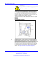
3
Connect one end of the CAT5e Ethernet cable to the network
interface located on the back of the IP Phone (identified with
a LAN icon, see Figure 3 "IP Phone 2001 Ethernet network
interface connections" (page 36)). The other end of the CAT5e
Ethernet cable plugs into the IP network.
The LAN Ethernet port supports Auto-Media Dependent Interface
Crossover (MDIX). Auto-MDIX is supported only when the
Ethernet port is configured for autonegotiation.
4
Connect the AC power adapter (optional). Leave the AC adapter
unplugged from the power outlet, connect the adapter to the AC
adapter jack in the bottom of the phone. Form a small bend in
the cable and then thread the adapter cord through the channels
in the stand.
Nortel Communication Server 1000
IP Phones Fundamentals
NN43001-368 05.02 26 May 2009
Copyright © 2003-2009 Nortel Networks. All Rights Reserved.
36 Nortel IP Phone 2001
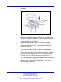
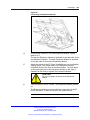
5
Secure the IP Phone footstand to the base of the IP Phone. Use
the angle adjustment grip on the top back of the IP Phone to
adjust the position.
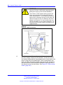
CAUTION
Damage to Equipment
Do not plug any device into your IP Phone 2001
Ethernet port other than an IEEE 802.3 Ethernet
network connection.
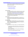
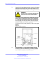
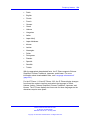
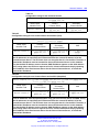
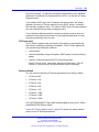
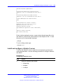
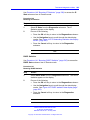
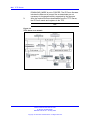
Figure 3
IP Phone 2001 Ethernet network interface connections
6
Power the IP Phone 2001 using either the Power over Ethernet
or an AC power transformer (local power). If you are using local
power, plug the AC power transformer into the nearest power
outlet. Make sure you use the correct AC power transformer is
used. The voltage rating of the transformer must match the wall
outlet voltage. See Table 4 "IP Phone 2001 components list"
(page 33).
The IP Phone 2001 supports both AC power and Power over
LAN options, including IEEE 802.3af Power Classification 2.
To use Power over Ethernet, where power is delivered over
the CAT5e cable, the LAN must support Power over Ethernet,
and an AC adapter is not required. To use local AC power, the
optional AC adapter can be ordered separately.
--End--
When you complete the IP Phone connection, you must connect the phone
to the network. See “Dynamic Host Configuration Protocol” (page 405).
Nortel Communication Server 1000
IP Phones Fundamentals
NN43001-368 05.02 26 May 2009
Copyright © 2003-2009 Nortel Networks. All Rights Reserved.
Redeploying an IP Phone 2001
37
Startup sequence
When an IP Phone 2001 connects to the network, it must perform a startup
sequence. The elements of the startup sequence include:
•
•
•
•
•
obtaining network access (if supported by the network infrastructure)
obtaining VLAN ID (if supported by the network infrastructure)
obtaining the IP parameters
connecting to the Call Server
obtaining the provisioning parameters
For information about provisioning the IP Phone, see “Manual provisioning
of IP Phone 2000 Series” (page 495).
Redeploying an IP Phone 2001
You can redeploy an existing previously configured IP Phone 2001 on
the same system. For example, the IP Phone 2001 can be assigned to
a new user (new TN) or to an existing user who moved to a new subnet
by changing the TN of the IP Phone 2001. For further information, see
Converging the Data Network with VoIP Fundamentals (NN43001-260).
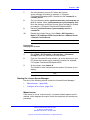
Procedure 3
Changing the TN of an existing IP Phone 2001
Step
Action
1
Repower the IP Phone 2001.
During the reboot sequence of a previously configured IP
Phone, the IP Phone 2001 displays the existing node number
for approximately five seconds.
2
If the node password is enabled and NULL, choose one of the
following:
a Disable the password.
b Set the password as non-NULL.
3
4
Press OK when the node number displays.
If
Then
the node password is enabled
and is not NULL
a password screen displays. Go
to Step 4.
the node password is disabled
a TN screen displays. Go to Step
5.
Enter password at the password screen, and press OK.
A TN screen displays.
Nortel Communication Server 1000
IP Phones Fundamentals
NN43001-368 05.02 26 May 2009
Copyright © 2003-2009 Nortel Networks. All Rights Reserved.
38 Nortel IP Phone 2001
To obtain the password, enter the nodePwdShow command in
Element Manager. For further information, see Element Manager
System Reference - Administration (NN43001-632).
5
Select the Clear soft key to clear the existing TN.
6
Enter the new TN.
--End--
Replacing an IP Phone 2001
ATTENTION
Two IP Phones cannot share the same TN. You must remove the IP Phone
2001 that currently uses the TN.
Procedure 4
Replacing an IP Phone 2001
Step
Action
1
Obtain the node and TN information of the phone you want to
replace.
2
Disconnect the IP Phone 2001 that you want to replace.
3
Follow to install the IP Phone 2001. To configure the IP Phone,
“Manual provisioning of IP Phone 2000 Series” (page 495).
4
Enter the same TN and Node Number as the IP Phone 2001 you
replaced. The system associates the new IP Phone 2001 with
the existing TN.
--End--
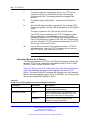
Removing an IP Phone 2001 from service
Procedure 5
Removing an IP Phone 2001 from service
Step
Action
1
Disconnect the IP Phone 2001 from the network or turn off the
power.
If the IP Phone 2001 was automatically configured, the DHCP
lease expires and the IP address returns to the available pool.
2
In LD 11, enter the following:
REQ: OUT
Nortel Communication Server 1000
IP Phones Fundamentals
NN43001-368 05.02 26 May 2009
Copyright © 2003-2009 Nortel Networks. All Rights Reserved.
Removing an IP Phone 2001 from service
TYPE: 2001P2
TN: LLL S CC UU
--End--
Nortel Communication Server 1000
IP Phones Fundamentals
NN43001-368 05.02 26 May 2009
Copyright © 2003-2009 Nortel Networks. All Rights Reserved.
39
40 Nortel IP Phone 2001
Nortel Communication Server 1000
IP Phones Fundamentals
NN43001-368 05.02 26 May 2009
Copyright © 2003-2009 Nortel Networks. All Rights Reserved.
41
.
Nortel IP Phone 2002
Contents
This section contains the following topics:
•
•
•
•
•
•
•
•
•
•
“Introduction” (page 41)
“Description” (page 42)
“Components and functions” (page 42)
“Features” (page 45)
“Display characteristics” (page 46)
“Package components” (page 47)
“Installation and configuration” (page 49)
“Redeploying an IP Phone 2002” (page 53)
“Replacing an IP Phone 2002” (page 54)
“Removing an IP Phone 2002 from service” (page 54)
Introduction
This section explains how to install and maintain the IP Phone 2002. For
information about using the IP Phone 2002, see the IP Phone 2002 User
Guide (NN43116-104).
This section contains the following procedures:
•
•
•
Procedure 6 “Configuring the IP Phone 2002” (page 50)
•
•
Procedure 9 “Replacing an IP Phone 2002” (page 54).
Procedure 7 “Connecting the components” (page 51)
Procedure 8 “Changing the TN of an existing IP Phone 2002” (page
53).
Procedure 10 “Removing an IP Phone 2002 from service” (page 54).
Nortel Communication Server 1000
IP Phones Fundamentals
NN43001-368 05.02 26 May 2009
Copyright © 2003-2009 Nortel Networks. All Rights Reserved.
42 Nortel IP Phone 2002
After you install and configure an IP Phone, if power to the phone is
interrupted, you need not re-enter the IP parameters, node number,
Terminal Number (TN), or reacquisition of firmware.
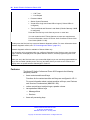
Description
The IP Phone 2002 uses the customer IP data network to communicate
with the Communication Server 1000 (CS 1000). The IP Phone 2002
translates voice into data packets for transport using Internet Protocol.
Use a Dynamic Host Configuration Protocol (DHCP) server to provide
information that you can use for the IP Phone 2002 network and CS 1000
connections.
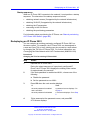
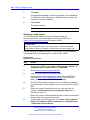
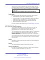
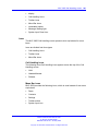
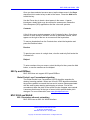
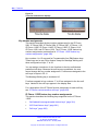
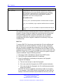
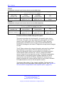
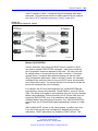
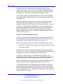
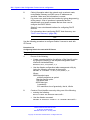
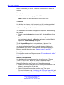
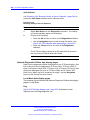
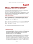
Figure 4 "IP Phone 2002" (page 42) shows the IP Phone 2002.
Figure 4
IP Phone 2002
Components and functions
This section describes the following components and functions of the IP
Phone 2002:
•
•
“Keys and functions” (page 43)
“Services menu” (page 44)
Nortel Communication Server 1000
IP Phones Fundamentals
NN43001-368 05.02 26 May 2009
Copyright © 2003-2009 Nortel Networks. All Rights Reserved.
Components and functions
43
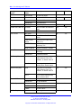
Keys and functions
Table 5 "IP Phone 2002 keys and functions" (page 43) describes the IP
Phone 2002 keys and functions.
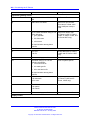
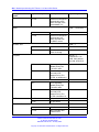
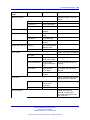
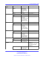
Table 5
IP Phone 2002 keys and functions
Key
Function
Speaker
Press the Line key to activate the speaker for on-hook dialing and
listening.
Programmable line
(DN)/feature keys
(self-labeled)
Programmable line (DN)/feature keys (self-labeled) are configured
for various features on the IP Phone. One must be the prime DN
key.
A steady LCD light beside a line (DN) key indicates the feature or
line is active. A flashing LCD indicates the line is on hold or the
feature is being programmed.
Message waiting light/
Incoming call indicator
The Message waiting light turns ON to indicate that a message has
been left for the user. This light also flashes when the set ringer is
ON.
Context-sensitive soft keys
(self-labeled)
Context-sensitive soft keys (self-labeled) are located below the
display area. The LCD label above the key changes, based on the
active feature.
A triangle before a key label indicates that the key is active.
Navigation keys
Use the navigation keys to scroll through menus and lists in the
display area.
Message (Inbox)
Press the Message (Inbox) key to access your voice mailbox.
Outbox/Shift
Press the Outbox/Shift key to switch between two feature key pages
and access an additional six lines/features.
Directory
Press the Directory key to access Directory services.
Quit
Press the Quit key to end an active application.
Pressing the Quit key does not affect the status of the calls currently
on your IP Phone.
Expand to PC
The Expand to PC key is used to access external server
applications such as External Application Server (XAS).
Goodbye
Press the Goodbye key to terminate an active call.
Hold
Press the Hold key to put an active call on hold. Press the line (DN)
key beside the flashing LCD to return to the caller on hold.
Headset
Press the Headset key to answer a call using the headset or to
switch a call from the handset or Handsfree to the headset.
Nortel Communication Server 1000
IP Phones Fundamentals
NN43001-368 05.02 26 May 2009
Copyright © 2003-2009 Nortel Networks. All Rights Reserved.
44 Nortel IP Phone 2002
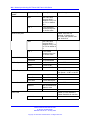
Table 5
IP Phone 2002 keys and functions (cont’d.)
Key
Function
Mute
Press the Mute key to listen to the receiving party without
transmitting.
Press the Mute key again to return to a two-way conversation.
The Mute key applies to Handsfree, Handset, and Headset
microphones.
The Mute LED flashes when the Mute option is in use.
Volume control bar
Use the volume control bar to adjust the volume of the handset,
headset, speaker, ringer, and, Handsfree feature.
Press the right side of the rocker bar to increase volume; press the
left side to decrease volume.
Handsfree key
Press the Handsfree key to activate the Handsfree feature.
The LED lights to indicate when handsfree is active.
Services menu
Table 6 "Services menu" (page 44) shows the Services menu.
Table 6
Services menu
Services key
Press the Services key to access the following items:
•
Telephone Options
— Volume Adjustment
— Contrast Adjustment
— Language
— Date/Time Format
— Display diagnostics
— Local Dialpad Tone
— Set Info
— Ring type
— OnHook Default Path
— Change Feature key label
— Call Timer
— Live Dialpad
Nortel Communication Server 1000
IP Phones Fundamentals
NN43001-368 05.02 26 May 2009
Copyright © 2003-2009 Nortel Networks. All Rights Reserved.
Features
45
— Normal Mode indication
— Caller ID display order
•
•
•
Password Administration
Virtual Office Login and Virtual Office Logout (if Virtual Office is configured)
Test Local Mode and Resume Local Mode (if Branch Office is configured)
You can customize the IP Phone features to meet user requirements. For
more information, see the IP Phone 2002 User Guide (NN43116-104).
Double-press the Services key to access Network diagnostic utilities. For more information about
Network diagnostic utilities, see “IP Phone diagnostic utilities” (page 531).
If an incoming call is presented while you configure information in the Services menu, the phone
rings. However, the display does not update with the caller ID, and the programming text is not
disturbed.
While you are in the Services menu you cannot dial digits but you can use the programmable line
keys, such as Redial (double-press a line key) and Auto dial key to make a call. However, the
display does not update with the dialed digits or Caller ID.
Features
The IP Phone 2002 supports the following telephony features:
•
•
four programmable line (DN)/feature keys (self-labeled)
four context-sensitive soft keys (self-labeled)
Functions for the context-sensitive soft keys are configured in LD 11.
For more information about context-sensitive soft keys, see Features
and Services Fundamentals (NN43001-106).
•
volume control bar to adjust ringer, speaker, handset, handsfree, and
headset volume
•
•
ability to change the programmable line (DN)/feature key labels
six specialized feature keys
— Quit
— Directory
— Message/Inbox
— Shift/Outbox
— Services
— Copy
•
six call-processing fixed keys:
Nortel Communication Server 1000
IP Phones Fundamentals
NN43001-368 05.02 26 May 2009
Copyright © 2003-2009 Nortel Networks. All Rights Reserved.
46 Nortel IP Phone 2002
— Mute
— Handsfree
— Goodbye
— Expand to PC
— Headset
— Hold
For more information about IP Phone features, see “Features” (page 369).
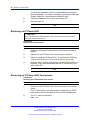
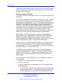
Display characteristics
An IP Phone 2002 has three major display areas:
•
•
•
“Programmable line (DN)/feature key label display” (page 47)
“Information line display” (page 47)
“Soft key label display” (page 47)
Figure 5 "IP Phone 2002 display areas" (page 46) shows these three
display areas.
Figure 5
IP Phone 2002 display areas
Cleaning the IP Phone display screen
Gently wipe the IP Phone display screen with a soft, dry cloth.
CAUTION
Do not use any liquids or powders on the IP Phone. Using
anything other than a soft, dry cloth can contaminate IP Phone
components and cause premature failure.
Nortel Communication Server 1000
IP Phones Fundamentals
NN43001-368 05.02 26 May 2009
Copyright © 2003-2009 Nortel Networks. All Rights Reserved.
Package components
47
Programmable line (DN)/feature key label display
The feature key label area displays a 10-character string for each of the
four feature keys. Each feature key includes the key label and an icon.
The icon state can be on, off, or flashing. A telephone icon displays the
status of the configured DN. Key labels are left-aligned for keys on the
left side of the screen, and right-aligned for keys on the right side of the
screen.
If a label is longer than 10 characters, the last 10 characters are displayed
and the excess characters are deleted from the beginning of the string.
Information line display
An IP Phone 2002 has a one-line information display area with the
following information:
•
•
•
•
•
caller number
caller name
feature prompt strings
user-entered digits
date and time information (if the IP Phone is in an idle state) or Call
Timer (if provisioned in the Telephone options menu)
The information in the display area changes, according to the
call-processing state and active features.
Because the IP Phone 2002 only has a one-line information display area,
you are prompted to scroll through any additional lines of information.
Soft key label display
The soft key label has a maximum six characters. Each soft key includes
the soft key label and an icon. When a soft key is in use, a triangle icon
appears at the beginning of the soft key label, and the label shifts one
character to the right. (If the label is six characters in length, the last or
rightmost character is truncated.) If a feature is enabled, the icon state
turns to On. The icon remains in the on state until the feature key is
pressed again. This cancels the enabled feature and turns the icon off,
and returns the soft key label to its original state.
Use the More soft key to navigate the layers of functions. If only four
functions are assigned to the soft keys, the More key does not appear,
and all four functions are displayed.
Package components
The following information applies to Phase II IP Phones. Product codes for
Phase II IP Phones are different from previous sets.
Nortel Communication Server 1000
IP Phones Fundamentals
NN43001-368 05.02 26 May 2009
Copyright © 2003-2009 Nortel Networks. All Rights Reserved.
48 Nortel IP Phone 2002
See the product code on the back of the phone to confirm whether it is a
Phase II IP Phone. The product code for Phase II IP Phones appears as
IP Phone 200x. The product code for previous versions of the IP Phone
appears with an i in front of the model number (for example, i200x).
You must order the AC power adapter separately if local power using the
AC adapter is required, because Phase II IP Phones include integrated
support for a number of power over LAN options, including support for
IEEE 802.3af standard power.
Table 7 "Package components" (page 48) lists the IP Phone 2002 package
components.
Table 7
Package components
•
•
•
•
•
IP Phone 2002
handset
handset cord
2.1 m (7-ft) CAT5e Ethernet cable
Getting Started Card
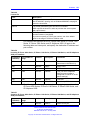
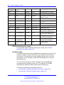
Table 8 "IP Phone 2002 components list" (page 48) lists the IP Phone
2002 components and product codes.
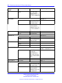
Table 8
IP Phone 2002 components list
Component
Product code
IP Phone 2002 (Ethergray) with Icon keycaps
NTDU91AA16/A0533404
IP Phone 2002 (Ethergray) with English text label keycaps
NTDU91BA16/A0533405
IP Phone 2002 (Charcoal) with Icon keycaps
NTDU91AA70/A0533406
IP Phone 2002 (Charcoal) with English text label keycaps
NTDU91BA70/A0533407
IP Phone 2002 (Charcoal with Bezel) with Icon keycaps
NTDU91AB70
IP Phone 2002 (Charcoal with Bezel) with Icon keycaps (RoHS)
NTDU91AC70E6
IP Phone 2002 (Charcoal with Bezel) with English text label keycaps
NTDU91BB70
IP Phone 2002 (Charcoal with Bezel) with English text label keycaps
(RoHS)
NTDU91BC70E6
Replacement parts
7 ft Cat5e Ethernet cable
N0177422
Handset, Ethergray
A0788874
Handset, Charcoal
A0758634
Handset cord, Ethergray
A0897725
Nortel Communication Server 1000
IP Phones Fundamentals
NN43001-368 05.02 26 May 2009
Copyright © 2003-2009 Nortel Networks. All Rights Reserved.
Installation and configuration
49
Table 8
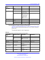
IP Phone 2002 components list (cont’d.)
Component
Product code
Handset cord, Charcoal
N0000763
Footstand, Charcoal (used for Ethergray and Charcoal models)
A0891619
Power Adapters
Global power supply (for local power)
IEC cables
RoHS
Non-RoHS
1.8 m (5.9 ft), 10 amp, IEC320-C13
North America
NTYS14AAE6
NTYS14AA
2.4 m (8 ft), 240 VAC 10 amp, ANZ
power cord AS-3,
Australia, New Zealand
N/A
NTTK15AA
250 VAC, Option 11C Standard
European power cord,
Other EMEA, Kenya, Korea, Thailand,
Indonesia, Vietnam, India, Pakistan
NTTK16ABE6
NTTK16AB
3 m (9.9 ft) 125 VAC, Option 11C Swiss
power cord
Switzerland
NTTK17ABE6
NTTK17AB
240 VAC, Option 11C UK power cord
Hong Kong, Ireland, United Kingdom,
Singapore, Malaysia, Bangladesh,
Brunei, Sri Lanka
NTTK18ABE6
NTTK18AB
3 m (9.9 ft), 125 VAC, Option 11C
Denmark power cord
Denmark
NTTK22ABE6
NTTK22AB
Argentina
N/A
A0814961
1.8 m (5.9 ft), 10 amp, IEC320-C13
Japan
NTTK26AAE6
N/A
For more information, and for information about previous versions of the IP
Phone, contact Nortel.
Installation and configuration
The following sections provide a step-by-step guide to install and configure
the IP Phone 2002:
•
•
•
“Before you begin” (page 50)
“First-time installation” (page 50)
“Configuring the IP Phone 2002” (page 50)
Nortel Communication Server 1000
IP Phones Fundamentals
NN43001-368 05.02 26 May 2009
Copyright © 2003-2009 Nortel Networks. All Rights Reserved.
50 Nortel IP Phone 2002
•
•
“Connecting the components” (page 51)
“Startup sequence” (page 53)
Before you begin
Before installing the IP Phone 2002, complete the following pre-installation
checklist:
•
Ensure one IP Phone 2002 boxed package exists for each IP Phone
2002 you install. For a list of IP Phone 2002 package components, see
Table 7 "Package components" (page 48).
•
Ensure one Software License exists for each IP Phone 2002 you
install.
•
Ensure the host Call Server is equipped with a Signaling Server that
runs the Line Terminal Proxy Server (LTPS) application.
•
If an AC power adapter is required, ensure you use the correct AC
power transformer. The voltage rating of the transformer must match
the wall outlet voltage. See Table 8 "IP Phone 2002 components list"
(page 48).
•
Ensure the latest IP Phone firmware is deployed to the IP telephony
node. For more information, see Signaling Server IP Line Applications
Fundamentals (NN43001-125).
First-time installation
You must first install an IP telephony node with the Communication Server.
For information about installing an IP telephony node, see Signaling Server
IP Line Applications Fundamentals (NN43001-125).
CAUTION
Do not plug your IP Phone 2002 into an ISDN connection.
Severe damage can result.
Configuring the IP Phone 2002
Use Procedure 6 “Configuring the IP Phone 2002” (page 50) to configure
the IP Phone 2002.
Procedure 6
Configuring the IP Phone 2002
Step
Action
1
Configure a virtual loop on the Call Server using LD 97.
Nortel Communication Server 1000
IP Phones Fundamentals
NN43001-368 05.02 26 May 2009
Copyright © 2003-2009 Nortel Networks. All Rights Reserved.
Installation and configuration
51
For more information about configuring a virtual loop, see
Signaling Server IP Line Applications Fundamentals (NN430
01-125) and Software Input Output Reference-Administration
(NN43001-611).
2
Configure the IP Phone 2002 on the Call Server using LD 11. At
the prompt, enter the following:
REQ:new
TYPE:2002P1,2002P2
For more information about configuring the IP Phone 2002 using
LD 11, see Software Input Output Reference-Administration
(NN43001-611).
3
Configure the IP Phone 2002 in Element Manager. IP Phones
are configured using the Phones section in the Element
Manager navigation tree. For more information about configuring
the IP Phone 2002 using Element Manager, see Element
Manager System Reference - Administration (NN43001-632).
--End--
Connecting the components
Use Procedure 7 “Connecting the components” (page 51) to connect the
components for the IP Phone.
Procedure 7
Connecting the components
Step
Action
1
Connect one end of the handset cord to the handset jack on the
back of the IP Phone (identified with a handset icon). See Figure
6 "IP Phone 2002 Ethernet network interface connections" (page
52)
2
Connect the other end of the handset cord to the handset.
3
Choose one of the following connections:
•
For an IP Phone not sharing LAN access with a PC:
Connect one end of the CAT5e Ethernet cable to the network
interface located on the back of the IP Phone (identified with
a LAN icon). The other end of the CAT5e Ethernet cable
plugs into the IP network.
•
For an IP Phone sharing LAN access with a PC:
Connect one end of the CAT5e Ethernet cable to the network
interface located on the back of the IP Phone (identified with
a LAN icon) and the other end to the IP network. Insert on
end of a second CAT5e Ethernet cable into the PC network
Nortel Communication Server 1000
IP Phones Fundamentals
NN43001-368 05.02 26 May 2009
Copyright © 2003-2009 Nortel Networks. All Rights Reserved.
52 Nortel IP Phone 2002
interface located on the back of the IP Phone (identified with
a PC icon) and the other end into the computer.
See Figure 6 "IP Phone 2002 Ethernet network interface
connections" (page 52).
The LAN Ethernet port supports Auto-Media Dependent Interface
Crossover (MDIX). Auto-MDIX is supported only when the
Ethernet port is configured for autonegotiation. The PC Port
does not support Auto-MDIX.
CAUTION
Damage to Equipment
Do not plug any device into your IP Phone 2002
Ethernet port other than an IEEE 802.3 Ethernet
network connection. The IP Phone 2002 does not
support multiple devices connected through the PC
Ethernet port.
Figure 6
IP Phone 2002 Ethernet network interface connections
4
Connect the AC power adapter (optional). Leave the AC adapter
unplugged from the power outlet, connect the adapter to the AC
adapter jack in the bottom of the phone. Form a small bend in
the cable and then thread the adapter cord through the channels
in the stand.
5
Secure the IP Phone footstand to the base of the IP Phone. Use
the angle adjustment grip on the top back of the IP Phone to
adjust the position.
6
Power the IP Phone 2002 using either the Power over Ethernet
or an AC power transformer (local power). If you are using local
power, plug the AC power transformer into the nearest power
outlet. Make sure you use the correct AC power transformer is
used. The voltage rating of the transformer must match the wall
outlet voltage. See Table 8 "IP Phone 2002 components list"
(page 48).
Nortel Communication Server 1000
IP Phones Fundamentals
NN43001-368 05.02 26 May 2009
Copyright © 2003-2009 Nortel Networks. All Rights Reserved.
Redeploying an IP Phone 2002
53
The IP Phone 2002 supports both AC power and Power over
LAN options, including IEEE 802.3af Power Classification 2.
To use Power over Ethernet, where power is delivered over
the CAT5e cable, the LAN must support Power over Ethernet,
and an AC adapter is not required. To use local AC power, the
optional AC adapter can be ordered separately.
--End--
When you complete the IP Phone connection, you must connect the phone
to the network. See “Dynamic Host Configuration Protocol” (page 405).
Startup sequence
When an IP Phone 2002 connects to the network, it must perform a startup
sequence. The elements of the startup sequence include:
•
•
•
•
•
obtaining network access (if supported by the network infrastructure)
obtaining VLAN ID (if supported by the network infrastructure)
obtaining the IP parameters
connecting to the Call Server
obtaining provisioning parameters
For information about provisioning the IP Phone, see “Manual provisioning
of IP Phone 2000 Series” (page 495).
Redeploying an IP Phone 2002
You can redeploy an existing previously configured IP Phone 2002 on the
same Call Server. For example, the IP Phone 2002 can be assigned to
a new user (new TN) or to an existing user who moved to a new subnet
by changing the TN of the IP Phone 2002. For further information, see
Converging the Data Network with VoIP Fundamentals (NN43001-260).
Procedure 8
Changing the TN of an existing IP Phone 2002
Step
Action
1
Repower the IP Phone 2002.
During the reboot sequence of a previously configured IP
Phone, the IP Phone 2002 displays the existing node number
for approximately 5 seconds.
2
If the node password is enabled and NULL, choose one of the
following:
a Disable the password.
b Set the password as non-NULL.
Nortel Communication Server 1000
IP Phones Fundamentals
NN43001-368 05.02 26 May 2009
Copyright © 2003-2009 Nortel Networks. All Rights Reserved.
54 Nortel IP Phone 2002
3
4
Press OK when the node number displays.
If
Then
the node password is enabled
and is not NULL
a password screen displays. Go
to Step 4.
the node password is disabled
a TN screen displays. Go to Step
5.
Enter the password at the password screen and press OK.
A TN screen displays.
To obtain the password, enter the nodePwdShow command in
Element Manager. For further information, see Element Manager
System Reference - Administration (NN43001-632).
5
Select the Clear soft key to clear the existing TN.
6
Enter the new TN.
--End--
Replacing an IP Phone 2002
ATTENTION
Two IP Phones cannot share the same TN. You must remove the IP Phone
2002 that currently uses the TN.
Procedure 9
Replacing an IP Phone 2002
Step
Action
1
Obtain the node and TN information of the phone you want to
replace.
2
Disconnect the IP Phone 2002 that you want to replace.
3
Follow to install the IP Phone 2002. To configure the IP Phone,
see “Manual provisioning of IP Phone 2000 Series” (page 495).
4
Enter the same TN and Node Number as the IP Phone 2002 you
replaced. The Call Server associates the new IP Phone 2002
with the existing TN.
--End--
Removing an IP Phone 2002 from service
Procedure 10
Removing an IP Phone 2002 from service
Nortel Communication Server 1000
IP Phones Fundamentals
NN43001-368 05.02 26 May 2009
Copyright © 2003-2009 Nortel Networks. All Rights Reserved.
Removing an IP Phone 2002 from service
Step
Action
1
Disconnect the IP Phone 2002 from the network or turn off the
power.
55
The service to the PC is disconnected as well if the PC connects
to the IP Phone 2002.
If the IP Phone 2002 was automatically configured, the DHCP
lease expires and the IP address returns to the available pool.
2
In LD 11, enter the following:
REQ: OUT
TYPE: 2002P1, 2002P2
TN: LLL S CC UU
--End--
Nortel Communication Server 1000
IP Phones Fundamentals
NN43001-368 05.02 26 May 2009
Copyright © 2003-2009 Nortel Networks. All Rights Reserved.
56 Nortel IP Phone 2002
Nortel Communication Server 1000
IP Phones Fundamentals
NN43001-368 05.02 26 May 2009
Copyright © 2003-2009 Nortel Networks. All Rights Reserved.
57
.
Nortel IP Phone 2004
Contents
This section contains the following topics:
•
•
•
•
•
•
•
•
•
“Introduction” (page 57)
“Description” (page 58)
“Components and functions” (page 58)
“Features” (page 61)
“Package components” (page 64)
“Installation and configuration” (page 66)
“Redeploying an IP Phone 2004” (page 70)
“Replacing an IP Phone 2004” (page 71)
“Removing an IP Phone 2004 from service” (page 71)
Introduction
This section explains how to install and maintain the IP Phone 2004. For
information about using the IP Phone 2004, see the IP Phone 2004 User
Guide (NN43117-102).
This section contains the following procedures:
•
•
•
Procedure 11 “Configuring the IP Phone 2004” (page 67)
•
•
Procedure 14 “Replacing an IP Phone 2004” (page 71).
Procedure 12 “Connecting the components” (page 68)
Procedure 13 “Changing the TN of an existing IP Phone 2004” (page
70).
Procedure 15 “Removing an IP Phone 2004 from service” (page 71).
After you install and configure an IP Phone, if power to the phone is
interrupted, you need not re-enter the IP parameters, node number,
Terminal Number (TN), or reacquisition of firmware.
Nortel Communication Server 1000
IP Phones Fundamentals
NN43001-368 05.02 26 May 2009
Copyright © 2003-2009 Nortel Networks. All Rights Reserved.
58 Nortel IP Phone 2004
Description
The IP Phone 2004 uses the customer IP data network to communicate
with the Communication Server 1000 (CS 1000). The IP Phone 2004
translates voice into data packets for transport using Internet Protocol.
Use a Dynamic Host Configuration Protocol (DHCP) server to provide
information that you can use for the IP Phone 2004 network and CS 1000
connections.
Figure 7 "IP Phone 2004" (page 58) shows the IP Phone 2004.
Figure 7
IP Phone 2004
Components and functions
This section describes the following components and functions of the IP
Phone 2004:
•
•
“Keys and functions” (page 58)
“Services menu” (page 60)
Keys and functions
Table 9 "IP Phone 2004 keys and functions" (page 59) shows the IP
Phone 2004 keys and functions.
Nortel Communication Server 1000
IP Phones Fundamentals
NN43001-368 05.02 26 May 2009
Copyright © 2003-2009 Nortel Networks. All Rights Reserved.
Components and functions
59
Table 9
IP Phone 2004 keys and functions
Key
Function
Hold
Press the Hold key to put an active call on hold. Press the line (DN) key
beside the flashing LCD to return to the caller on hold.
Goodbye
Press the Goodbye key to terminate an active call.
Message waiting light/
Incoming call indicator
The Message waiting indicator turns ON to indicate that a message has
been left for the user. This indicator also flashes when the set ringer is
ON.
Programmable line
(DN)/feature keys
(self-labeled)
Programmable line (DN)/feature keys (self-labeled) are configured for
various features on the IP Phones.
A steady LCD light beside a line (DN) key indicates the feature or line is
active. A flashing LCD indicates the line is on hold or the feature is being
programmed.
Context-sensitive soft
keys (self-labeled)
Context-sensitive soft keys (self-labeled) are located below the display
area. The LCD label above the key changes, based on the active feature.
A triangle before a key label indicates that the key is active.
Fixed feature keys
Use these keys to access non-programmable standard features.
Expand to PC
The Expand to PC key is used to access external server applications
such as External Application Server.
Copy
A fixed key reserved for future feature development. An audible
non-working tone is generated along with a display message.
Navigation keys
Use the navigation keys to scroll through menus and lists in the display
area.
Outbox/Shift
Press the Outbox/Shift key to switch between two feature key pages and
access an additional six lines/features.
Message (Inbox)
Press the Message (Inbox) key to access your voice mailbox.
Quit
Press the Quit key to end an active application.
Pressing the Quit key does not affect the status of the calls currently on
your IP Phone.
Directory
Press the Directory key to access Directory services.
Mute
Press the Mute key to listen to the receiving party without transmitting.
Press the Mute key again to return to a two-way conversation.
The Mute key applies to Handsfree, Handset, and Headset microphones.
The Mute LED flashes when the Mute option is in use.
Nortel Communication Server 1000
IP Phones Fundamentals
NN43001-368 05.02 26 May 2009
Copyright © 2003-2009 Nortel Networks. All Rights Reserved.
60 Nortel IP Phone 2004
Table 9
IP Phone 2004 keys and functions (cont’d.)
Key
Function
Headset
Press the Headset key to answer a call using the headset or to switch a
call from the handset or Handsfree to the headset.
Volume control bar
Use the Volume control bar to adjust the volume of the handset, headset,
speaker, ringer, and Handsfree feature.
Press the right side of the rocker bar to increase volume, the left side to
decrease volume.
Handsfree key
Press the Handsfree key to activate handsfree.
The LED lights to indicate when the handsfree feature is active.
Services menu
Table 10 "Services menu" (page 60) shows the Services menu.
Table 10
Services menu
Services key
Press the Services key to access the following items:
•
Telephone Options
— Volume Adjustment
— Contrast Adjustment
— Language
— Date/Time Format
— Display diagnostics
— Local Dialpad Tone
— Ring type
— Call Timer
— OnHook Default Path
— Change Feature Key Label
— Set Info
— Live Dialpad
•
•
•
Password Administration
Virtual Office Login and Virtual Office Logout (if Virtual Office is configured)
Test Local Mode and Resume Local Mode (if Branch Office is configured)
Nortel Communication Server 1000
IP Phones Fundamentals
NN43001-368 05.02 26 May 2009
Copyright © 2003-2009 Nortel Networks. All Rights Reserved.
Features
61
You can customize the IP Phone features to meet user requirements. For
more information, see the IP Phone 2004 User Guide (NN43117-102).
Double-press the Services key to access Network diagnostic utilities. For more information about
Network diagnostic utilities, see “IP Phone diagnostic utilities” (page 531).
If an incoming call is presented while you configure information in the Services menu, the phone
rings. However, the display does not update with the caller ID, and the programming text is not
disturbed.
While you are in the Services menu you cannot dial digits but you can use the programmable line
keys, such as Redial (double-press a line key) and Auto dial key to make a call. However, the
display does not update with the dialed digits or Caller ID.
During an incoming call, if the selected feature page does not contain the flashing DN line key, the
display reverts to the active feature key page. This enables the user to answer the call without
pressing the Shift key.
Features
The IP Phone 2004 supports the following telephony features:
•
•
six programmable line (DN)/feature keys (self-labeled)
four context-sensitive soft keys (self-labeled)
Functions for the context-sensitive soft keys are configured in LD 11.
For more information about context-sensitive soft keys, see Features
and Services Fundamentals (NN43001-106).
•
volume control bar to adjust ringer, speaker, handset, handsfree, and
headset volume
•
•
ability to change the programmable line (DN)/feature key labels
six specialized feature keys
— Quit
— Directory
— Message/Inbox
— Shift/Outbox
— Services
— Copy
•
six call-processing fixed keys
— Mute
— Handsfree
— Goodbye
Nortel Communication Server 1000
IP Phones Fundamentals
NN43001-368 05.02 26 May 2009
Copyright © 2003-2009 Nortel Networks. All Rights Reserved.
62 Nortel IP Phone 2004
— Expand to PC
— Headset
— Hold
For more information about IP Phone features, see “Features” (page 369)
Central Answering Position
The Central Answering Position (CAP) operates as an Automatic
Call Distribution (ACD) agent on the IP Phone 2004. A CAP provides
call-handling features, such as transferring a call, parking a call, and
answering a call. You can add an IP Phone Key Expansion Module (KEM)
to provide additional lines and features, Direct Station Select, and Busy
Lamp Field functionality.
For further information about Central Answering Position, see Central
Answering Position Implementation Guide (NN43011-501).
Display characteristics
An IP Phone 2004 has three major display areas:
•
•
•
“Programmable line (DN)/feature key label display” (page 63)
“Information line display” (page 63)
“Soft key label display” (page 63)
Figure 8 "IP Phone 2004 display areas" (page 62) shows the three display
areas.
Figure 8
IP Phone 2004 display areas
Nortel Communication Server 1000
IP Phones Fundamentals
NN43001-368 05.02 26 May 2009
Copyright © 2003-2009 Nortel Networks. All Rights Reserved.
Display characteristics
63
Cleaning the IP Phone display screen
Gently wipe the IP Phone display screen with a soft, dry cloth.
CAUTION
Do not use any liquids or powders on the IP Phone. Using
anything other than a soft, dry cloth can contaminate IP Phone
components and cause premature failure.
Programmable line (DN)/feature key label display
The feature key label area displays a 10-character string for each of the
four feature keys. Each feature key includes the key label and an icon.
The icon state can be on, off, or flashing. A telephone icon displays the
status of the configured DN. Key labels are left-aligned for keys on the
left side of the screen, and right-aligned for keys on the right side of the
screen.
If a label is longer than 10 characters, the last 10 characters are displayed,
and the excess characters are deleted from the beginning of the string.
Information line display
An IP Phone 2004 has a three-line information display area with the
following information:
•
•
•
•
•
caller number
caller name
feature prompt strings
user-entered digits
date and time information (if the IP Phone is in an idle state) or Call
Timer (if provisioned in the Telephone options menu)
The information in the display area changes, according to the
call-processing state and active features.
Soft key label display
The soft key label has a maximum six characters. Each soft key includes
the soft key label and an icon. When a soft key is in use, a triangle icon
appears at the beginning of the soft key label, and the label shifts one
character to the right. (If the label is seven characters in length, the last or
rightmost character is truncated.) If a feature is enabled, the icon state
turns to On. The icon remains in the on state until the feature key is
pressed again. This cancels the enabled feature and turns the icon off,
and returns the soft key label to its original state.
Nortel Communication Server 1000
IP Phones Fundamentals
NN43001-368 05.02 26 May 2009
Copyright © 2003-2009 Nortel Networks. All Rights Reserved.
64 Nortel IP Phone 2004
Use the More soft key to navigate the layers of functions. If there are only
four functions assigned to the soft keys, the More key does not appear,
and all four functions are displayed.
Package components
The following information applies to Phase II IP Phones. Product codes for
Phase II IP Phones are different from previous sets.
See the product code on the back of the phone to confirm whether it is a
Phase II IP Phone. The product code for Phase II IP Phones appears as
IP Phone 200x. The product code for previous versions of the IP Phone
appears with an i in front of the model number (for example, i200x).
You must order the AC power adapter separately if local power using the
AC adapter is required, because Phase II IP Phones include integrated
support for a number of power over LAN options, including support for
IEEE 802.3af standard power.
Table 11 "Package components" (page 64) lists the IP Phone 2004
package components.
Table 11
Package components
•
•
•
•
•
IP Phone 2004
handset
handset cord
2.1 m (7-ft) CAT5e Ethernet cable
Getting Started Card
Table 12 "IP Phone 2004 component list" (page 64) lists the IP Phone
2004 components and product codes.
Table 12
IP Phone 2004 component list
Component
Product code
IP Phone 2004 (Ethergray) with Icon keycaps
NTDU92AA16/A0533408
IP Phone 2004 (Ethergray) with English text label
keycaps
NTDU92BA16/A0533409
IP Phone 2004 (Charcoal) with Icon keycaps
NTDU92AA70/A0533410
IP Phone 2004 (Charcoal) with English text label
keycaps
NTDU92BA70/A0533411
IP Phone 2004 (Charcoal with Bezel) with Icon keycaps
NTDU92AB70
Nortel Communication Server 1000
IP Phones Fundamentals
NN43001-368 05.02 26 May 2009
Copyright © 2003-2009 Nortel Networks. All Rights Reserved.
Package components
Table 12
IP Phone 2004 component list (cont’d.)
Component
Product code
IP Phone 2004 (Charcoal with Bezel) with Icon keycaps
(RoHS)
NTDU92AC70E6
IP Phone 2004 (Charcoal with Bezel) with English text
label keycaps
NTDU92BB70
IP Phone 2004 (Charcoal with Bezel) with English text
label keycaps (RoHS)
NTDU92BC70E6
IP Phone 2004 wall mount kit (Charcoal), used with
Ethergray and Charcoal models
NTMN15BA70/A0503076
Replacement parts
7 ft Ethernet Cat5e cable
N0177422
Handset (Ethergray)
A0788874
Handset (Charcoal)
A0758634
Handset cord (Ethergray)
A0788682
Handset cord (Charcoal)
N0000764
Footstand (Charcoal), used for Ethergray and Charcoal
models
A0538587
IP Phone 2002/2004 Power Adapters
Global power supply (for local power)
N0089601
IEC cables
RoHS
Non-RoHS
1.8 m (5.9 ft), 10 amp, IEC320-C13
North America
NTYS14AAE6
NTYS14AA
2.4 m (8 ft), 240 VAC 10 amp, ANZ
power cord AS-3,
Australia, New Zealand
N/A
NTTK15AA
250 VAC, Option 11C Standard
European power cord,
Other EMEA, Kenya, Korea, Thailand,
Indonesia, Vietnam, India, Pakistan
NTTK16ABE6
NTTK16AB
3 m (9.9 ft) 125 VAC, Option 11C Swiss
power cord
Switzerland
NTTK17ABE6
NTTK17AB
240 VAC, Option 11C UK power cord
Hong Kong, Ireland, United Kingdom,
Singapore, Malaysia, Bangladesh,
Brunei, Sri Lanka
NTTK18ABE6
NTTK18AB
Nortel Communication Server 1000
IP Phones Fundamentals
NN43001-368 05.02 26 May 2009
Copyright © 2003-2009 Nortel Networks. All Rights Reserved.
65
66 Nortel IP Phone 2004
IP Phone 2002/2004 Power Adapters
3 m (9.9 ft), 125 VAC, Option 11C
Denmark power cord
Denmark
NTTK22ABE6
NTTK22AB
Argentina
N/A
A0814961
1.8 m (5.9 ft), 10 amp, IEC320-C13
Japan
NTTK26AAE6
N/A
For more information, and for information about previous versions of the IP
Phone, contact your Nortel representative.
Installation and configuration
The following sections provide a step-by-step guide to install and configure
the IP Phone 2004:
•
•
•
•
•
“Before you begin” (page 66)
“First-time installation” (page 67)
“Configuring the IP Phone 2004” (page 67)
“Connecting the components” (page 67)
“Startup sequence” (page 70)
Before you begin
Before installing the IP Phone 2004, complete the following pre-installation
checklist:
•
Ensure one IP Phone 2004 boxed package exists for each IP Phone
2004 you install. For a list of IP Phone 2004 package components, see
Table 11 "Package components" (page 64).
•
Ensure one Software License exists for each IP Phone 2004 you
install.
•
Ensure the host Call Server is equipped with a Signaling Server that
runs the Line TPS application.
•
If an AC power adapter is required, ensure you use the correct AC
power transformer. The voltage rating of the transformer must match
the wall outlet voltage. See Table 12 "IP Phone 2004 component list"
(page 64).
•
Ensure the latest IP Phone firmware is deployed to the IP telephony
node. For more information, see Signaling Server IP Line Applications
Fundamentals (NN43001-125).
Nortel Communication Server 1000
IP Phones Fundamentals
NN43001-368 05.02 26 May 2009
Copyright © 2003-2009 Nortel Networks. All Rights Reserved.
Installation and configuration
67
First-time installation
You must first install an IP telephony node with the Communication Server.
For information about installing an IP telephony node, see Signaling Server
IP Line Applications Fundamentals (NN43001-125).
CAUTION
Do not plug your IP Phone 2004 into an ISDN connection.
Severe damage can result.
Configuring the IP Phone 2004
Use Procedure 11 “Configuring the IP Phone 2004” (page 67) to configure
the IP Phone 2004 for the first time.
Procedure 11
Configuring the IP Phone 2004
Step
Action
1
Configure a virtual loop on the Call Server using LD 97.
For more information about configuring a virtual loop, see
Signaling Server IP Line Applications Fundamentals (NN430
01-125) and Software Input Output Reference-Administration
(NN43001-611).
2
Configure the IP Phone 2004 on the Call Server using LD 11. At
the prompt, enter the following:
REQ:new
TYPE:2004P1,2004P2
For more information about configuring the IP Phone 2004 using
LD 11, see Software Input Output Reference-Administration
(NN43001-611).
3
Configure the IP Phone 2004 in Element Manager. IP Phones
are configured using the Phones section in the Element
Manager navigation tree. For more information about configuring
the IP Phone 2004 using Element Manager, see Element
Manager System Reference - Administration (NN43001-632).
--End--
Connecting the components
Use Procedure 12 “Connecting the components” (page 68) to connect the
components for the IP Phone.
Nortel Communication Server 1000
IP Phones Fundamentals
NN43001-368 05.02 26 May 2009
Copyright © 2003-2009 Nortel Networks. All Rights Reserved.
68 Nortel IP Phone 2004
Procedure 12
Connecting the components
Step
Action
1
Connect one end of the handset cord to the handset jack on the
back of the IP Phone (identified with a handset icon). See Figure
9 "IP Phone 2004 Ethernet network connections" (page 69).
2
Connect the other end of the handset cord to the handset.
3
Choose one of the following connections:
•
For an IP Phone not sharing a LAN access with a PC:
Connect one end of the CAT5e Ethernet cable to the LAN
Ethernet port located on the back of the IP Phone 2004
(identified with a LAN icon). The other end of the CAT5e
Ethernet cable plugs into the IP network.
•
For an IP Phone sharing a LAN access with a PC:
Connect one end of the CAT5e Ethernet cable to the LAN
Ethernet port located on the back of the IP Phone (identified
with a LAN icon) and the other end to the IP network. Insert
one end of a second CAT5e Ethernet cable into the PC
Ethernet port located on the back of the IP Phone (identified
with a PC icon) and the other end into the computer.
See Figure 9 "IP Phone 2004 Ethernet network connections"
(page 69).
The LAN Ethernet port supports Auto-Media Dependent Interface
Crossover (MDIX). Auto-MDIX is supported only when the
Ethernet port is configured for autonegotiation. The PC Port
does not support Auto-MDIX.
CAUTION
Damage to Equipment
Do not plug any device into your IP Phone 2004
Ethernet port other than an IEEE 802.3 Ethernet
network connection. The IP Phone 2004 does not
support multiple devices connected through the PC
Ethernet port.
Nortel Communication Server 1000
IP Phones Fundamentals
NN43001-368 05.02 26 May 2009
Copyright © 2003-2009 Nortel Networks. All Rights Reserved.
Installation and configuration
69
Figure 9
IP Phone 2004 Ethernet network connections
4
Connect the AC power adapter (optional). Leave the AC adapter
unplugged from the power outlet, connect the adapter to the AC
adapter jack in the bottom of the phone. Form a small bend in
the cable and then thread the adapter cord through the channels
in the stand.
5
Secure the IP Phone footstand to the base of the IP Phone. Use
the angle adjustment grip on the top back of the IP Phone to
adjust the position.
6
Power the IP Phone 2004 using either the Power over Ethernet
or an AC power transformer (local power). If you are using local
power, plug the AC power transformer into the nearest power
outlet. Make sure you use the correct AC power transformer is
used. The voltage rating of the transformer must match the wall
outlet voltage. See Table 12 "IP Phone 2004 component list"
(page 64).
The IP Phone 2004 supports both AC power and Power over
LAN options, including IEEE 802.3af Power Classification 2.
To use Power over Ethernet, where power is delivered over
the CAT5e cable, the LAN must support Power over Ethernet,
and an AC adapter is not required. To use local AC power, the
optional AC adapter can be ordered separately.
--End--
Nortel Communication Server 1000
IP Phones Fundamentals
NN43001-368 05.02 26 May 2009
Copyright © 2003-2009 Nortel Networks. All Rights Reserved.
70 Nortel IP Phone 2004
When you complete the IP Phone connection, you must connect the phone
to the network. See “Dynamic Host Configuration Protocol” (page 405).
Startup sequence
When an IP Phone 2004 connects to the network, it must perform a startup
sequence. The elements of the startup sequence include:
•
•
•
•
•
obtaining network access (if supported by the network infrastructure)
obtaining VLAN ID (if supported by the network infrastructure)
obtaining the IP parameters
connecting to the Call Server
obtaining the provisioning parameters
For information about provisioning the IP Phone, see “Manual provisioning
of IP Phone 2000 Series” (page 495).
Redeploying an IP Phone 2004
You can redeploy an existing previously configured IP Phone 2004 on the
same Call Server. For example, the IP Phone 2004 can be assigned to
a new user (new TN) or to an existing user who moved to a new subnet
by changing the TN of the IP Phone 2004. For further information, see
Converging the Data Network with VoIP Fundamentals (NN43001-260).
Procedure 13
Changing the TN of an existing IP Phone 2004
Step
Action
1
Repower the IP Phone 2004.
During the reboot sequence of a previously configured IP
Phone, the IP Phone 2004 displays the existing node number
for approximately five seconds.
2
If the node password is enabled and NULL, choose one of the
following:
a Disable the password.
b Set the password as non-NULL.
3
Press OK when the node number displays.
If
Then
the node password is enabled
and is not NULL
a password screen displays. Go
to Step 4.
the node password is disabled
a TN screen displays. Go to Step
5.
Nortel Communication Server 1000
IP Phones Fundamentals
NN43001-368 05.02 26 May 2009
Copyright © 2003-2009 Nortel Networks. All Rights Reserved.
Removing an IP Phone 2004 from service
4
71
Enter the password at the password screen, and press OK.
A TN screen displays.
To obtain the password, enter the nodePwdShow command in
Element Manager. For further information, see Element Manager
System Reference - Administration (NN43001-632).
5
Select the Clear soft key to clear the existing TN.
6
Enter the new TN.
--End--
Replacing an IP Phone 2004
ATTENTION
Two IP Phones cannot share the same TN. You must remove the IP Phone
2004 that currently uses the TN.
Procedure 14
Replacing an IP Phone 2004
Step
Action
1
Obtain the node and TN information of the phone you want to
replace.
2
Disconnect the IP Phone 2004 that you want to replace.
3
Follow to install the IP Phone 2004. To configure the IP Phone,
see “Manual provisioning of IP Phone 2000 Series” (page 495).
4
Enter the same TN and Node Number as the IP Phone 2004 you
replaced. The Call Server associates the new IP Phone 2004
with the existing TN.
--End--
Removing an IP Phone 2004 from service
Procedure 15
Removing an IP Phone 2004 from service
Step
Action
1
Disconnect the IP Phone 2004 from the network or turn the
power off.
The service to the PC is disconnected as well if the PC connects
to the IP Phone 2004.
If the IP Phone 2004 was automatically configured, the DHCP
lease expires and the IP address returns to the available pool.
Nortel Communication Server 1000
IP Phones Fundamentals
NN43001-368 05.02 26 May 2009
Copyright © 2003-2009 Nortel Networks. All Rights Reserved.
72 Nortel IP Phone 2004
2
In LD 11, enter the following:
REQ: OUT
TYPE: 2004P1, 2004P2
TN: LLL S CC UU
--End--
Nortel Communication Server 1000
IP Phones Fundamentals
NN43001-368 05.02 26 May 2009
Copyright © 2003-2009 Nortel Networks. All Rights Reserved.
73
.
IP Phone Key Expansion Module (KEM)
Contents
This section contains the following topics
•
•
•
•
•
•
•
•
•
“Description” (page 73)
“Features” (page 74)
“Display characteristics” (page 74)
“Key number assignments” (page 75)
“Package components” (page 75)
“Configuration” (page 75)
“Installation” (page 78)
“IP Phone KEM startup initialization” (page 79)
“Operating parameters” (page 80)
Description
The Nortel IP Phone Key Expansion Module (KEM) is a hardware
component that connects to IP Phone 2002 and IP Phone 2004 and
provides additional line appearances and feature keys (see Figure 10 "IP
Phone 2002 with one IP Phone KEM attached" (page 74)).
Up to two IP Phone KEMs can be connected to an IP Phone 2002 or IP
Phone 2004. With two IP Phone KEMs connected, the IP Phone can have
up to 48 additional line/feature keys.
The IP Phone 2004 can also have up to 48 additional line/feature keys
using the Shift key functionality and one IP Phone KEM. With two IP
Phone KEMs connected, the Shift key functionality does not affect the IP
Phone KEMs since the maximum number of line/feature keys is already
available. The IP Phone 2002 does not support Shift key functionality.
Nortel Communication Server 1000
IP Phones Fundamentals
NN43001-368 05.02 26 May 2009
Copyright © 2003-2009 Nortel Networks. All Rights Reserved.
74 IP Phone Key Expansion Module (KEM)
Figure 10
IP Phone 2002 with one IP Phone KEM attached
Features
The IP Phone KEM has the following features:
•
12 keys on each side of an LCD provide up to 24 additional
self-labeled line/feature keys. Using the Shift key functionality, an IP
Phone 2004 can have up to 48 additional logical line/feature keys.
•
A desk-mount bracket and structural baseplate connect the IP Phone
KEM to an IP Phone 2002 or IP Phone 2004, or to another IP Phone
KEM.
•
A wall-mount bracket installs the IP Phone KEM alongside a
wall-mounted IP Phone 2002 or IP Phone 2004.
Display characteristics
The IP Phone KEM has one LCD between the two rows of 12 Line/feature
keys (see Figure 10 "IP Phone 2002 with one IP Phone KEM attached"
(page 74)). Each of the 24 physical keys on the IP Phone KEM has a
10-character display label. This label is set automatically, however, the
user can edit the label using the controls on the IP Phone.
Nortel Communication Server 1000
IP Phones Fundamentals
NN43001-368 05.02 26 May 2009
Copyright © 2003-2009 Nortel Networks. All Rights Reserved.
Configuration
75
To alter the display and contrast on the IP Phone KEM, use the Contrast
Adjustment option under the Telephone Options menu on the IP Phone.
Any contrast changes you make on the IP Phone affect the IP Phone
KEM. The IP Phone KEM and IP Phone do not have separate contrast
adjustments.
Key number assignments
Since the IP Phone 2002 and IP Phone 2004 have key number
assignments from 0 to 31, the IP Phone KEM key number assignments
begin at 32. Therefore, the first IP Phone KEM has key number
assignments from 32 to 55, and the second IP Phone KEM has key
number assignments from 56 to 79.
For more information about key number assignments, see “IP Phone
context-sensitive soft keys” (page 605).
Package components
Table 13 "IP Phone KEM components list" (page 75) lists the IP Phone
KEM package components.
Table 13
IP Phone KEM components list
Components
Order code
IP Phone KEM - Ethergray
A0540989
IP Phone KEM - Charcoal
A0540990
IP Phone KEM wall mount kit - Charcoal
A0555218
Configuration
The IP Phone KEM must be configured in LD 11 before it is used.
Table 14
LD 11: Configure the IP Phone KEM
Prompt
Response
Description
REQ:
NEW CHG
Add new data. Change existing data.
TYPE:
2002P2
IP Phone 2002
2004P2
IP Phone 2004
...
ZONE
...
0 – 255
Zone number to which the IP Phone 2002 or IP Phone
2004 belongs
Nortel Communication Server 1000
IP Phones Fundamentals
NN43001-368 05.02 26 May 2009
Copyright © 2003-2009 Nortel Networks. All Rights Reserved.
76 IP Phone Key Expansion Module (KEM)
Table 14
LD 11: Configure the IP Phone KEM (cont’d.)
Prompt
Response
Description
KEM
(0) – 2
Number of attached IP Phone KEMs
Up to two IP Phone KEMs can be attached to an IP
Phone. Pressing <CR> without entering a number leaves
the value unchanged.
....
KEY
xx aaa yyyy (cccc or D) zz..z
Telephone function key assignments
The following key assignments determine calling options
and features available to an IP Phone. Note that KEY is
prompted until a carriage return <CR> is entered.
Where:
xx = key number
aaa = key name or function
yyy = additional information required for the key
zz.z = additional information required for the key aaa.
The cccc or D entry deals specifically with the Calling Line
Identification feature, where:
cccc = CLID table entry of (0)-N, where N = the value
entered at the SIZE prompt in LD 15 minus 1.
D = the character "D". When the character "D" is entered,
the system searches the DN keys from key 0 and up,
to find a DN key with a CLID table entry. The CLID
associated with the found DN key is then used.
The position of the (cccc or D) field varies depending on
the key name or function.
You may enter a CLID table entry if aaa = ACD, HOT d,
HOT L, MCN, MCR, PVN, PVR, SCN, or SCR.
Type xx NUL to remove a key function or feature.
Nortel Communication Server 1000
IP Phones Fundamentals
NN43001-368 05.02 26 May 2009
Copyright © 2003-2009 Nortel Networks. All Rights Reserved.
Configuration
77
Table 14
LD 11: Configure the IP Phone KEM (cont’d.)
Prompt
Response
Description
PAGEOFST
<Page>
<KeyOffset>
Automatically calculates the IP Phone KEM key based
on the entered values. This prompt enables the system
administrator to enter a Page number of 0 or 1 and a
Key Offset number from 0 to 23. Once entered, the KEY
prompt is prompted with the appropriate KEY value filled
in.
Enter <CR> to terminate data entry.
Applies to an IP Phone 2004 with
KEM = 1, and where <CR> was entered at the KEY
prompt.
Does not apply to an IP Phone 2002.
When values are entered for Page and KeyOffset, the
KEY xx prompt displays, followed by PAGEOFST prompt.
This loop continues until no values (<CR> only) are
entered at the PAGEOFST prompt.
KEY xx
Edit the IP Phone KEM key number specified by
PAGEOFST, where:
xx = the number of the key (for example, KEY 36)
Enter <CR> to keep the current setting.
KEMOFST
<KEM>
<KeyOffset>
Automatically calculates the IP Phone KEM key based
on the entered values. This prompt enables the system
administrator to enter a KEM number of 1 or 2 and a Key
Offset number from 0-23. Once entered, the KEY prompt
is prompted with the appropriate KEY value filled in.
Enter <CR> to terminate data entry.
When values are entered for KEM and KeyOffset, the KEY
xx prompt displays, followed by KEMOFST prompt. This
loop continues until no values (<CR> only) are entered at
the KEMOFST prompt.
Applies to an IP Phone 2002 if <CR> was entered at the
KEY prompt.
Nortel Communication Server 1000
IP Phones Fundamentals
NN43001-368 05.02 26 May 2009
Copyright © 2003-2009 Nortel Networks. All Rights Reserved.
78 IP Phone Key Expansion Module (KEM)
Table 14
LD 11: Configure the IP Phone KEM (cont’d.)
Prompt
Response
Description
Applies to an IP Phone 2004 with
KEM = 2, and where <CR> was entered at the KEY
prompt.
KEY xx
Edit the IP Phone KEM key number specified by
KEMOFST, where:
xx = the number of the key (for example, KEY 36)
Enter <CR> to keep the current setting.
Installation
The IP Phone KEM mounts on the right side of an IP Phone 2002 or IP
Phone 2004. The IP Phone KEM snaps into the receptacle on the back
of the IP Phone using the desk-mount bracket and structural baseplate
supplied with the IP Phone KEM (see Figure 11 "IP Phone KEM attached
to an IP Phone 2002" (page 78)).
The IP Phone KEM connects to the IP Phone 2002 or IP Phone 2004
using the Accessory Expansion Module (AEM) port on the IP Phone.
Figure 11
IP Phone KEM attached to an IP Phone 2002
Nortel Communication Server 1000
IP Phones Fundamentals
NN43001-368 05.02 26 May 2009
Copyright © 2003-2009 Nortel Networks. All Rights Reserved.
IP Phone KEM startup initialization 79
Procedure 16
Connecting the IP Phone KEM to an IP Phone 2002 or IP Phone 2004
Step
Action
1
Remove the IP Phone from the stand by pressing the IP Phone
tilt handle, and pulling the IP Phone away from the stand.
For the IP Phone 2004, you can also adjust the stand angle to
maximum, instead of removing the stand.
2
Place the connecting arm of the IP Phone KEM behind the IP
Phone and align the IP Phone KEM connection plug to the AEM
port on the back of the IP Phone.
The IP Phones 2002 with the product codes: NTDU76AB34,
NTDU76BB34, NTDU76AB70, and NTDU76BB70 have shorter
connector pins than the other IP Phone 2002. Therefore, the
ribbon cable connector of the IP Phone KEM must be detached
from the retaining clip and pressed manually into the header
connector before attaching the IP Phone KEM.
3
Press the IP Phone KEM and IP Phone firmly together until the
IP Phone KEM locks into place.
4
If connecting a second IP Phone KEM, repeat steps 1 to 3.
The second IP Phone KEM is attached to the right side of the
first IP Phone KEM.
5
Attach the IP Phone stand and the IP Phone KEM stand, if
removed. Adjust each IP Phone KEM stand to the same angle
as the IP Phone.
The IP Phone KEM powers up.
The IP Phone KEM uses the electrical connection of the IP
Phone 2002 or IP Phone 2004 for power. It does not have its
own power source.
--End--
IP Phone KEM startup initialization
Once the IP Phone KEM has been installed and powered up on your IP
Phone 2002 or IP Phone 2004, the IP Phone KEM initializes (see Table 15
"Startup initialization process for the IP Phone KEM" (page 80)).
Nortel Communication Server 1000
IP Phones Fundamentals
NN43001-368 05.02 26 May 2009
Copyright © 2003-2009 Nortel Networks. All Rights Reserved.
80 IP Phone Key Expansion Module (KEM)
Table 15
Startup initialization process for the IP Phone KEM
Phase
Description
1. IP Phone KEM performs
self-test
The self-test confirms the operation of the IP Phone KEM local
memory, CPU, and other circuitry. While undergoing this self-test,
the IP Phone KEM display lights up.
If the IP Phone KEM display does not light up, or lights up and then
goes blank, or fails to begin flashing, check that the IP Phone KEM
is correctly installed and configured.
2. IP Phone KEM
establishes communication
with the IP Phone
The IP Phone KEM display flashes until it establishes
communication with the IP Phone.
If the IP Phone KEM display does not stop flashing, communication
has not been established with the IP Phone. Check that the IP
Phone KEM is correctly installed and configured.
3. IP Phone KEM
downloads keymaps
The key labels download to the IP Phone KEM. During the
download, the display is blank.
When the three phases complete successfully, you are ready to use the
additional line/feature keys on your IP Phone KEM.
If you have a second IP Phone KEM installed on your IP Phone, the one to
the immediate right of the IP Phone must be functional for the subsequent
IP Phone KEM to work. This is because the second IP Phone KEM
receives its power, and communicates with the IP Phone, through the first
IP Phone KEM.
Operating parameters
General
If an IP Phone KEM is not responding, and lines or features are configured
on keys 32 to 79, calls can be directed to those keys which the user
cannot access. This means the IP Phone 2002 or IP Phone 2004 rings but
the call cannot be answered. In such cases, the incoming call receives
Call Forward No Answer (CFNA) treatment.
IP Phone 2002
If only one IP Phone KEM is configured in LD 11, but two IP Phone KEMs
are detected on an IP Phone 2002, the second IP Phone KEM is ignored.
An error message displays to alert the administrator that the hardware
configuration does not match the administered configuration.
If two IP Phone KEMs are configured in LD 11, but only one IP Phone
KEM is responding, the keys on the second IP Phone KEM are available
for call processing but are not accessible to the user. This means that
Nortel Communication Server 1000
IP Phones Fundamentals
NN43001-368 05.02 26 May 2009
Copyright © 2003-2009 Nortel Networks. All Rights Reserved.
Operating parameters
81
lines and features on keys 56 to 79 can cause the IP Phone 2002 to
ring, but there is no way to answer it. An error message displays to alert
the administrator that the hardware configuration does not match the
administered configuration.
IP Phone 2004
If only one IP Phone KEM is configured in LD 11, but two IP Phone KEMs
are detected on an IP Phone 2004, the Terminal Proxy Server (TPS)
assigns keys 56 to 79 to the second IP Phone KEM. An error message
displays to alert the administrator that the hardware configuration does not
match the administered configuration.
If two IP Phone KEMs are configured in LD 11 but only one IP Phone
KEM is responding, the TPS assigns keys 32 to 79 to the single IP Phone
KEM (using the Shift key functionality). An error message displays to
alert the administrator that the hardware configuration does not match the
administered configuration. When a second IP Phone KEM is detected,
the TPS changes the key assignments to display across both IP Phone
KEMs, as expected.
Virtual Office
When a Virtual Office (VO) login occurs from an IP Phone 2002 or IP
Phone 2004 that does not have the same number of IP Phone KEMs
responding as configured on the IP Phone used to log in, call processing
may terminate on a key that is not physically available. In other words, the
IP Phone rings but the call cannot be answered.
During the VO login process, the existence of any IP Phone KEM is
verified. If a mismatch is detected, the login proceeds normally; however,
an error message is generated to alert the administrator of the mismatch.
Firmware
The IP Phone KEM firmware is not downloadable. If the IP Phone KEM
firmware must be upgraded or changed, the IP Phone KEM must be
replaced with a new IP Phone KEM containing the updated firmware.
Nortel Communication Server 1000
IP Phones Fundamentals
NN43001-368 05.02 26 May 2009
Copyright © 2003-2009 Nortel Networks. All Rights Reserved.
82 IP Phone Key Expansion Module (KEM)
Nortel Communication Server 1000
IP Phones Fundamentals
NN43001-368 05.02 26 May 2009
Copyright © 2003-2009 Nortel Networks. All Rights Reserved.
83
.
Nortel IP Audio Conference Phone
2033
Contents
•
•
•
•
•
•
•
•
•
•
•
“Introduction” (page 83)
•
“Connecting an extension microphone” (page 99)
“Description” (page 84)
“Extension microphones” (page 85)
“Components and functions” (page 86)
“Features” (page 88)
“Display characteristics” (page 89)
“Package components” (page 91)
“Installation and configuration” (page 93)
“Redeploying an IP Audio Conference Phone 2033” (page 97)
“Replacing an IP Audio Conference Phone 2033” (page 98)
“Removing an IP Audio Conference Phone 2033 from service” (page
99)
Introduction
This section explains how to install and maintain the IP Audio Conference
Phone 2033. For information about using the IP Audio Conference Phone
2033, see the IP Phone Audio Conference Phone 2033 User Guide
(NN43111-100).
This section contains the following procedures:
•
Procedure 17 “Configuring the IP Audio Conference Phone 2033”
(page 94)
•
Procedure 18 “Connecting the components” (page 95)
Nortel Communication Server 1000
IP Phones Fundamentals
NN43001-368 05.02 26 May 2009
Copyright © 2003-2009 Nortel Networks. All Rights Reserved.
84 Nortel IP Audio Conference Phone 2033
•
Procedure 19 “Changing the TN of an existing IP Audio Conference
Phone 2033” (page 98)
•
Procedure 20 “Replacing an IP Audio Conference Phone 2033” (page
98)
•
Procedure 21 “Removing an IP Audio Conference Phone 2033 from
service” (page 99)
After you install and configure an IP Phone, if power to the phone is
interrupted, you need not re-enter the IP parameters, node number,
Terminal Number (TN), or reacquisition of firmware.
Description
The IP Audio Conference Phone 2033 uses the customer IP data network
to communicate with the Communication Server 1000 (CS 1000). The
IP Audio Conference Phone 2033 translates voice into data packets for
transport using Internet Protocol. Use a Dynamic Host Configuration
Protocol (DHCP) server to provide information that you can use for the IP
Audio Conference Phone 2033 network and CS 1000 connections.
Figure 12 "IP Audio Conference Phone 2033" (page 85) shows the IP
Audio Conference Phone 2033.
Nortel Communication Server 1000
IP Phones Fundamentals
NN43001-368 05.02 26 May 2009
Copyright © 2003-2009 Nortel Networks. All Rights Reserved.
Extension microphones
85
Figure 12
IP Audio Conference Phone 2033
Extension microphones
The IP Audio Conference Phone 2033 supports up to two extension
microphones that extend the microphone range in large rooms. Each
extension microphone has a Mute button and an LED indicator to indicate
the current mute state.
Figure 13 "Extension microphone" (page 86) shows an extension
microphone.
Nortel Communication Server 1000
IP Phones Fundamentals
NN43001-368 05.02 26 May 2009
Copyright © 2003-2009 Nortel Networks. All Rights Reserved.
86 Nortel IP Audio Conference Phone 2033
Figure 13
Extension microphone
Components and functions
This section describes the following components and functions of the IP
Audio Conference Phone 2033:
•
•
“Keys and functions” (page 86)
“Services menu” (page 87)
Keys and functions
Table 16 "IP Audio Conference Phone 2033 keys and functions" (page
86) describes the IP Audio Conference Phone 2033 keys and functions.
Table 16
IP Audio Conference Phone 2033 keys and functions
Key
Function
Line key
Use the Line key to access the single line and activate on-hook
dialing.
Volume control buttons
Use the Volume control buttons to adjust the volume of the ringer
and speaker.
Mute button
Use the Mute button on the main unit or any extension microphone
to mute the speaker.
Pressing the Mute button on the extension microphone toggles the
mute state of the entire IP Phone, not just the microphone.
Nortel Communication Server 1000
IP Phones Fundamentals
NN43001-368 05.02 26 May 2009
Copyright © 2003-2009 Nortel Networks. All Rights Reserved.
Components and functions
87
Table 16
IP Audio Conference Phone 2033 keys and functions (cont’d.)
Key
Function
Goodbye key
Use the Goodbye key to terminate an active call.
Hold key
Press the Hold key to put an active call on hold. Press the Line (DN)
key to return to the caller on hold.
Message (Inbox) key
Press the Message (Inbox) key to access your voice mailbox.
Navigation keys
Use the Navigation keys to scroll through menus and lists that
appear on the LCD display screen.
Arrows appear on the left side of display screen to indicate there is
more information to be displayed.
Context-sensitive soft keys
Context-sensitive soft keys (self-labeled) are located below the LCD
screen display. The LCD screen display above the key changes,
based on the active feature. See “Soft key label display” (page
90) for further information.
Press the Shift soft key labelled >> to access the second row of soft
keys.
When a triangle appears before a key label, the feature is active.
Services menu
Table 17 "Services menu" (page 87) shows the Services menu.
Table 17
Services menu
Services key
Press the Services key to access the following items:
•
Telephone Options
— Volume adjustment
— Contrast adjustment
— Language
— Date/Time
— Local DialPad Tone
— Set Info
— Diagnostics
— Ring type
Nortel Communication Server 1000
IP Phones Fundamentals
NN43001-368 05.02 26 May 2009
Copyright © 2003-2009 Nortel Networks. All Rights Reserved.
88 Nortel IP Audio Conference Phone 2033
— Call Timer
— Live Dialpad
•
•
•
Password Admin
•
Test Local Mode and Resume Local Mode (if Media Gateway 1000B
is configured)
Station Control Password
Virtual Office Login and Virtual Office Logout (if Virtual Office is
configured)
Press the Services key to exit from any menu or menu item.
You can customize the IP Phone features to meet user requirements.
For more information, see the IP Phone Audio Conference Phone 2033
User Guide (NN43111-100).
Double-press the Services key to access Network diagnostic utilities. For more information about
Network diagnostic utilities, see “IP Phone diagnostic utilities” (page 531).
Network diagnostic utilities is available in Remote Mode only.
If an incoming call is presented while you configure information in the Services menu, the phone
rings. However, the display does not update with the caller ID, and the programming text is not
disturbed.
While you are in the Services menu you cannot dial digits but you can use the programmable line
keys, such as Redial (double-press a line key) and Auto dial key to make a call. However, the
display does not update with the dialed digits or Caller ID.
Features
The Nortel IP Audio Conference Phone 2033 supports the following
telephony features:
•
three context-sensitive soft keys
Functions for the context-sensitive soft keys are configured in LD 11.
For more information about context-sensitive soft keys, see Features
and Services Fundamentals (NN43001-106).
•
•
volume control keys to adjust ringer, speaker volume
two specialized feature keys
— Message/Inbox
— Services
•
three call processing keys
Nortel Communication Server 1000
IP Phones Fundamentals
NN43001-368 05.02 26 May 2009
Copyright © 2003-2009 Nortel Networks. All Rights Reserved.
Display characteristics
89
— Mute
— Goodbye
— Hold
For more information about IP Phone features, see “Features” (page 369).
Display characteristics
The IP Audio Conference Phone 2033 has two display areas:
•
•
“Information line display” (page 90)
“Soft key label display” (page 90)
Figure 14 "IP Audio Conference Phone 2033 display areas" (page
89) shows the two display areas.
Figure 14
IP Audio Conference Phone 2033 display areas
Cleaning the IP Phone display screen
Gently wipe the IP Phone display screen with a soft, dry cloth.
CAUTION
Do not use any liquids or powders on the IP Phone. Using
anything other than a soft, dry cloth can contaminate IP Phone
components and cause premature failure.
Nortel Communication Server 1000
IP Phones Fundamentals
NN43001-368 05.02 26 May 2009
Copyright © 2003-2009 Nortel Networks. All Rights Reserved.
90 Nortel IP Audio Conference Phone 2033
Information line display
The IP Audio Conference Phone 2033 has a one-line information display
area with the following information:
•
•
•
•
•
caller number
•
set information
caller name
feature prompt strings
user-entered digits
date and time information (if the IP Phone is in an idle state) or Call
Timer (if provisioned in the Telephone options menu)
The information in the display area changes, according to the
call-processing state and active features.
Soft key label display
The soft key label has a maximum of seven characters. Each soft key
includes the soft key label and an icon. When a soft key is in use, a
triangle icon displays at the beginning of the soft key label, and the label
shifts one character to the right. (If the label is six characters in length, the
last or rightmost character is truncated.) If a soft key is enabled, the icon
state changes to on. It remains in the on state until the soft key is pressed
again. This cancels the enabled soft key and turns the icon off, returning
the soft key label to its original state.
Use the Shift (>>) key to navigate through the layers of functions. If only
three functions are assigned to the soft keys, the Shift (>>) key does not
appear, and all three functions are displayed.
Figure 15 "Soft keys" (page 90) shows the soft keys on the display area.
Figure 15
Soft keys
Nortel Communication Server 1000
IP Phones Fundamentals
NN43001-368 05.02 26 May 2009
Copyright © 2003-2009 Nortel Networks. All Rights Reserved.
Package components
91
Package components
Table 18 "Components list for US, CA, CALA, AP, and GC" (page
91) lists the components for the IP Audio Conference Phone 2033 for the
Americas, Asia Pacific, and Greater China region.
Table 18
Components list for US, CA, CALA, AP, and GC
Component
Product code
IP Audio Conference Phone 2033 package contents include
NTEX11AA70
•
•
•
•
IP Audio Conference Phone 2033 (charcoal)
7 ft Cat5e Ethernet cable
Power Interface Module (PIM) with 25 ft. console cable
IP Audio Conference Phone 2033 Quick Reference Card
Universal power supply
IP Audio Conference Phone 2033 package contents include
•
•
•
•
•
NTEX11BA70
IP Audio Conference Phone 2033 (charcoal)
7ft Cat5e Ethernet cable
Power over Ethernet (PoE) Module with 25 ft. console cable
IP Audio Conference Phone 2033 Quick Reference Card
2 Extension microphones (charcoal)
Universal power supply
IP Audio Conference Phone 2033 package contents include
•
•
•
•
NTEX11EA70
IP Audio Conference Phone 2033 (charcoal)
7 ft Cat5e Ethernet cable
Power over Ethernet (PoE) module with 25 ft. console cable
IP Audio Conference Phone 2033 Quick Reference Card
Universal power supply
Accessories
Power accessory kit (PIM, Universal power supply, cabling)
NTEX11CA
Power over Ethernet module
NTEX11GAE6
Extension microphone with 7-ft. cable
NTEX11DA70
Table 19 "Components list for EMEA" (page 92) lists the components for
Europe, Middle East and Africa (EMEA) regions.
Nortel Communication Server 1000
IP Phones Fundamentals
NN43001-368 05.02 26 May 2009
Copyright © 2003-2009 Nortel Networks. All Rights Reserved.
92 Nortel IP Audio Conference Phone 2033
Table 19
Components list for EMEA
Component
Product code
IP Audio Conference Phone 2033 package contents include
NTEX11AA70E6
•
•
•
IP Audio Conference Phone 2033 (charcoal)
7 ft Cat5e Ethernet cable
Power over Ethernet (PoE) module with 25 ft. console cable
IP Audio Conference Phone 2033 Quick Reference Card
IP Audio Conference Phone 2033 package contents include
•
•
•
•
NTEX11BA70E6
IP Audio Conference Phone 2033 (charcoal)
7-ft. CAT5e Ethernet cable
Power over Ethernet (PoE) module with 25 ft. console cable
IP Audio Conference Phone 2033 Quick Reference Card
2 Extension microphones (charcoal)
IP Audio Conference Phone 2033 package contents include
•
•
•
•
•
NTEX11EA70E6
IP Audio Conference Phone 2033 (charcoal)
7 ft Cat5e Ethernet cable
Power over Ethernet (PoE) module with 25 ft. console cable
IP Audio Conference Phone 2033 Quick Reference Card
Universal Power Supply
IP Audio Conference Phone 2033 package contents include
NTEX11FA70E6
IP Audio Conference Phone 2033 (charcoal)
•
•
•
•
•
7 ft Cat5e Ethernet cable
Power over Ethernet (PoE) module with 25 ft. console cable
IP Audio Conference Phone 2033 Quick Reference Card
2 Extension microphones (charcoal) with cables
Universal Power Supply
Accessories
•
•
•
Universal Power Supply (order power cord separately)
NTEX11CAE6
Power over Ethernet module
NTEX11GAE6
Extension microphones (charcoal) with cables
NTEX11DA70E6
Nortel Communication Server 1000
IP Phones Fundamentals
NN43001-368 05.02 26 May 2009
Copyright © 2003-2009 Nortel Networks. All Rights Reserved.
Installation and configuration
93
Table 19
Components list for EMEA (cont’d.)
Table 20 "Power cords" (page 93) lists the IP Audio Conference Phone
2033 power cords.
Table 20
Power cords
IP Audio Conference Phone 2033 power cords
NA NEMA 5-15P, 125V 13A (10ft.)
NTTK14AB
Euro CEE (7) VII, 250V, 10A (2.5m)
NTTK16AB
ANZ AS3112, 250V 10A (2.5m)
NTTK15AA
Swiss SEV 1011, 250V 10A (8ft.)
NTTK17AB
UK/Ireland BS1363, 240V 10A (8ft.)
NTTK18AB
Denmark AFSNIT, 250V 10A (2.5m)
NTTK22AB
Argentina IRAM 2073, 250V 10A (8ft.)
A0814961
Japan 1.8 m (5.9 ft), 10 amp, IEC320-C13
NTTK26AAE6
Installation and configuration
The following sections provide a step-by-step guide to install and configure
the IP Audio Conference Phone 2033:
•
•
•
•
•
“Before you begin” (page 93)
“First-time installation” (page 94)
“Configuring the IP Audio Conference Phone 2033” (page 94)
“Connecting the components” (page 95)
“Startup sequence” (page 97)
Before you begin
Before installing the IP Audio Conference Phone 2033, complete the
following pre-installation checklist:
•
Ensure one Software License exists for each IP Audio Conference
2033 Phone you install.
•
Ensure one IP Audio Conference Phone 2033 boxed package exists
for each IP Audio Conference Phone 2033 you install. See Table
18 "Components list for US, CA, CALA, AP, and GC" (page 91) or
Table 19 "Components list for EMEA" (page 92) for a list of package
contents.
•
Ensure the host Call Server is equipped with a Signaling Server that
runs the Line TPS application.
Nortel Communication Server 1000
IP Phones Fundamentals
NN43001-368 05.02 26 May 2009
Copyright © 2003-2009 Nortel Networks. All Rights Reserved.
94 Nortel IP Audio Conference Phone 2033
•
If an AC power adapter is required, ensure you use the correct AC
power transformer. The voltage rating of the transformer must match
the wall outlet voltage. See Table 18 "Components list for US, CA,
CALA, AP, and GC" (page 91) or Table 19 "Components list for EMEA"
(page 92).
•
Ensure the latest IP Phone firmware is deployed to the IP telephony
node. For more information, see Signaling Server IP Line Applications
Fundamentals (NN43001-125).
First-time installation
You must first install an IP telephony node with the Communication Server.
For information about installing an IP telephony node, see Signaling Server
IP Line Applications Fundamentals (NN43001-125).
CAUTION
Service Interruption
Do not plug your IP Audio Conference Phone 2033 into an ISDN
connection. Severe damage can result.
Configuring the IP Audio Conference Phone 2033
Use Procedure 17 “Configuring the IP Audio Conference Phone 2033”
(page 94) to configure the IP Audio Conference Phone 2033 for the first
time.
Procedure 17
Configuring the IP Audio Conference Phone 2033
Step
Action
1
Configure a virtual loop on the system using LD 97.
For more information about configuring a virtual loop, see
Signaling Server IP Line Applications Fundamentals (NN430
01-125) and Software Input Output Reference-Administration
(NN43001-611).
2
Configure the IP Audio Conference Phone 2033 on the system
using LD 11. At the prompts, enter the following:
REQ:new
TYPE:2033
TN lll s cc uu
ECHG yes
ITEM cls
ITEM
For more information about configuring the IP Audio Conference
Phone 2033 using LD 11, see Software Input Output
Reference-Administration (NN43001-611).
Nortel Communication Server 1000
IP Phones Fundamentals
NN43001-368 05.02 26 May 2009
Copyright © 2003-2009 Nortel Networks. All Rights Reserved.
Installation and configuration
3
95
Configure the IP Audio Conference Phone 2033 in Element
Manager. IP Phones are configured using the Phones section
in the Element Manager navigation tree. For more information
about configuring the IP Audio Conference Phone 2033 using
Element Manager, see Element Manager System Reference Administration (NN43001-632).
--End--
Connecting the components
Use Procedure 18 “Connecting the components” (page 95) to connect the
components for the IP Phone.
Procedure 18
Connecting the components
Step
Action
1
Connect one end of the CAT5d Ethernet cable to the network
interface located on the back of the Power over Ethernet (PoE)
module. See Figure 16 "POE module" (page 96). Plug the other
end of the CAT5e Ethernet cable into your IP network interface.
2
Connect the CAT5e Ethernet cable attached to the PoE module
to the IP Phone. Thread the CAT5e Ethernet cable through the
channel on the bottom of the IP Phone and plug it into the PoE
module port on the IP Phone.
The PoE module port supports Auto-Media Dependent Interface
Crossover (MDIX). Auto-MDIX is supported only when the
Ethernet port is configured for autonegotiation.
3
Connect the AC power adapter (optional) to the power supply
port located on the back of the PoE module, Leave the AC
power adapter unplugged from the power outlet. Thread the
cord through the channel on the bottom of the PoE module then
plug the other end into the AC power source. Ensure you use
the correct AC power transformer. The voltage rating of the
transformer must match the wall outlet voltage. See Table 18
"Components list for US, CA, CALA, AP, and GC" (page 91) or
Table 19 "Components list for EMEA" (page 92).
Figure 16 "POE module" (page 96) shows the Power over
Ethernet (PoE) module.
Nortel Communication Server 1000
IP Phones Fundamentals
NN43001-368 05.02 26 May 2009
Copyright © 2003-2009 Nortel Networks. All Rights Reserved.
96 Nortel IP Audio Conference Phone 2033
Figure 16
POE module
Red LEDs on the IP Audio Conference Phone 2033 indicate
power. Messages indicating system start up, such as Loading,
Initializing network, and Loading boot parameters appear after
a short delay.
Figure 17 "Bottom view of IP Audio Conference Phone 2033"
(page 97) shows the bottom view of the IP Audio Conference
Phone 2033.
The IP Audio Conference Phone 2033 supports both AC power
and Power over LAN options, including IEEE 802.3af Power
Classification 0. To use Power over Ethernet, where power is
delivered over the CAT5e cable, the LAN must support Power
over Ethernet, and an AC adapter is not required. To use local
AC power, the optional AC adapter can be ordered separately.
Nortel Communication Server 1000
IP Phones Fundamentals
NN43001-368 05.02 26 May 2009
Copyright © 2003-2009 Nortel Networks. All Rights Reserved.
Redeploying an IP Audio Conference Phone 2033
97
Figure 17
Bottom view of IP Audio Conference Phone 2033
--End--
When you complete the IP Phone connection, you must connect the phone
to the network. See “Dynamic Host Configuration Protocol” (page 405).
Startup sequence
When an IP Audio Conference Phone 2033 connects to the network, it
must perform a startup sequence. The elements of the startup sequence
include:
•
•
•
•
•
obtaining network access (if supported by the network infrastructure)
obtaining VLAN ID (if supported by the network infrastructure)
obtaining the IP parameters
connecting to the Call Server
obtaining provisioning parameters
For information about provisioning the IP Phone, see “Manual provisioning
of IP Phone 2000 Series” (page 495).
Redeploying an IP Audio Conference Phone 2033
You can redeploy an existing previously configured IP Audio Conference
Phone 2033 on the same system. For example, the IP Audio Conference
Phone 2033 can be assigned to a new user (new TN) or to an existing
user who moved to a new subnet by changing the TN of the IP Audio
Conference Phone 2033. For further information, see Converging the Data
Network with VoIP Fundamentals (NN43001-260).
Nortel Communication Server 1000
IP Phones Fundamentals
NN43001-368 05.02 26 May 2009
Copyright © 2003-2009 Nortel Networks. All Rights Reserved.
98 Nortel IP Audio Conference Phone 2033
Procedure 19
Changing the TN of an existing IP Audio Conference Phone 2033
Step
Action
1
Repower the IP Audio Conference Phone 2033.
During the reboot sequence of a previously configured the
IP Audio Conference Phone 2033 displays the existing node
number for approximately five seconds.
2
If the node password is enabled and NULL, choose one of the
following:
a Disable the password.
b Set the password as non-NULL.
3
4
Press OK when the node number displays.
If
Then
the node password is enabled
and is not NULL
a password screen displays. Go
to Step 4.
the node password is disabled
a TN screen displays. Go to Step
5.
Enter the password at the password screen, and press OK.
A TN screen displays.
To obtain the password, enter the nodePwdShow command in
Element Manager. For further information, see Element Manager
System Reference - Administration (NN43001-632).
5
Select the Shift soft key labeled (>>) and press Clear to edit the
TN field. The IP Audio Conference Phone 2033 by default places
you in the units field of the TN. You cannot use backspace to
move to the loop, shelf or card fields.
6
Enter the new TN.
--End--
Replacing an IP Audio Conference Phone 2033
ATTENTION
Two IP Phones cannot share the same TN. You must remove the IP Audio
Conference Phone 2033 that currently uses the TN.
Procedure 20
Replacing an IP Audio Conference Phone 2033
Nortel Communication Server 1000
IP Phones Fundamentals
NN43001-368 05.02 26 May 2009
Copyright © 2003-2009 Nortel Networks. All Rights Reserved.
Connecting an extension microphone
99
Step
Action
1
Obtain the node and TN information of the phone you want to
replace.
2
Disconnect the IP Audio Conference Phone 2033 that you want
to replace.
3
Follow to install the IP Audio Conference Phone 2033. To
configure the IP Phone, see “Manual provisioning of IP Phone
2000 Series” (page 495).
4
Enter the same TN and Node Number as the IP Audio
Conference Phone 2033 you replaced. The system associates
the new IP Audio Conference Phone 2033 with the existing TN.
--End--
Removing an IP Audio Conference Phone 2033 from service
Procedure 21
Removing an IP Audio Conference Phone 2033 from service
Step
Action
1
Disconnect the IP Audio Conference Phone 2033 from the
network or turn off the power.
If the IP Audio Conference Phone 2033 was automatically
configured, the DHCP lease expires and the IP address returns
to the available pool.
2
In LD 11, enter the following:
REQ: OUT
TYPE: 2033
TN: LLL S CC UU
--End--
Connecting an extension microphone
Procedure 22
Connecting an extension microphone to the IP Audio Conference Phone
2033
Step
Action
1
Thread the microphone cord through the channels on the bottom
of the IP Phone.
A maximum of two microphone jacks are supported on the IP
Audio Conference Phone 2033.
Nortel Communication Server 1000
IP Phones Fundamentals
NN43001-368 05.02 26 May 2009
Copyright © 2003-2009 Nortel Networks. All Rights Reserved.
100
Nortel IP Audio Conference Phone 2033
2
Connect the microphone cord to one of the microphone jacks on
the bottom of the IP Phone.
--End--
Nortel Communication Server 1000
IP Phones Fundamentals
NN43001-368 05.02 26 May 2009
Copyright © 2003-2009 Nortel Networks. All Rights Reserved.
101
.
Nortel IP Phone 2007
Contents
This section contains the following topics:
•
•
•
•
•
•
•
•
•
•
•
•
•
“Introduction” (page 101)
“Description” (page 102)
“Components and functions” (page 102)
“Features” (page 106)
“Touch panel” (page 107)
“Dialpad entry” (page 108)
“Cleaning the IP Phone display screen” (page 109)
“Display characteristics” (page 109)
“Package components” (page 112)
“Installation and configuration” (page 114)
“Redeploying an IP Phone 2007” (page 118)
“Replacing an IP Phone 2007” (page 119)
“Removing an IP Phone 2007 from service” (page 119)
Introduction
This section explains how to install and maintain the IP Phone 2007. For
information about using the IP Phone 2007, see the IP Phone 2007 User
Guide (NN43118-100).
This section contains the following procedures:
•
•
•
Procedure 24 “Configuring the IP Phone 2007” (page 115)
Procedure 25 “Connecting the components” (page 115)
Procedure 26 “Changing the TN of an existing IP Phone 2007” (page
118).
Nortel Communication Server 1000
IP Phones Fundamentals
NN43001-368 05.02 26 May 2009
Copyright © 2003-2009 Nortel Networks. All Rights Reserved.
102
Nortel IP Phone 2007
•
•
Procedure 27 “Replacing an IP Phone 2007” (page 119).
Procedure 28 “Removing an IP Phone 2007 from service” (page 119).
After you install and configure an IP Phone, if power to the phone is
interrupted, you need not re-enter the IP parameters, node number,
Terminal Number (TN), or reacquisition of firmware.
Description
The IP Phone 2007 uses the customer IP data network to communicate
with the Communication Server 1000 (CS 1000). The IP Phone 2007
translates voice into data packets for transport using Internet Protocol.
Use a Dynamic Host Configuration Protocol (DHCP) server to provide
information that you can use for the IP Phone 2007 network and CS 1000
connections.
Figure 18 "IP Phone 2007" (page 102) shows the IP Phone 2007.
Figure 18
IP Phone 2007
Components and functions
This section describes the following components and functions of the IP
Phone 2007:
•
•
•
“Keys and functions” (page 103)
“Services menu” (page 104)
“Local Tools menu” (page 105)
Nortel Communication Server 1000
IP Phones Fundamentals
NN43001-368 05.02 26 May 2009
Copyright © 2003-2009 Nortel Networks. All Rights Reserved.
Components and functions
103
Keys and functions
Table 21 "IP Phone 2007 keys and functions" (page 103) lists the keys
and functions for the IP Phone 2007.
Table 21
IP Phone 2007 keys and functions
Key
Function
Hold
Press the Hold key to put an active call on hold. Tap the flashing line
(DN) soft key to return to the caller on hold.
Goodbye
Press the Goodbye key to terminate an active call.
Handsfree
Press the Handsfree key to activate handsfree.
The LED lights to indicate when the handsfree feature is active.
Headset
Press the Headset key to answer a call using the headset or to switch a
call from the handset or handsfree to the headset.
Mute
Press the Mute key to listen to the receiving party without transmitting.
Press the Mute key again to return to a two-way conversation. The Mute
key applies to handsfree, handset, and headset microphones.
The Mute LED flashes when the Mute option is in use.
Volume control bar
Use the Volume control bar to adjust the volume of the ringer, handset,
headset, speaker, and the Handsfree feature.
Press the right side of the rocker bar to increase volume, the left side to
decrease volume.
Message waiting
light/incoming call
indicator
The Message waiting indicator turns ON to indicate that a message has
been left for the user. This indicator also flashes when the set ringer is
ON.
Programmable line
(DN)/feature keys
(self-labeled)
Programmable line (DN)/feature keys (self-labeled) are located on the
touch panel display and are configured for various features on the IP
Phones.
A steady LCD light beside a programmable line (DN)/feature key
indicates the feature or line is active. A flashing LCD indicates the line is
on hold or the feature is being programmed.
Context-sensitive soft
keys (self-labeled)
Context-sensitive soft keys (self-labeled) are located on the touch panel
display. The soft key label changes, based on the active feature.
Tap the More soft key to access the next layer of soft key functions.
Nortel Communication Server 1000
IP Phones Fundamentals
NN43001-368 05.02 26 May 2009
Copyright © 2003-2009 Nortel Networks. All Rights Reserved.
104
Nortel IP Phone 2007
Table 21
IP Phone 2007 keys and functions (cont’d.)
Key
Function
Navigation keys
Use the navigation keys to scroll through menus and lists on the LCD
display screen. The key rocks for up, down, left, and right movement.
Context-sensitive keys
The soft key labels are enabled for the keys on either side of the
navigation cluster. The labels are context sensitive. When in an edit box,
the soft key labels appear as Clear and Backspace. This allows numeric
editing without using the soft keyboard. In normal use the soft key labels
show Quit and Copy.
Services menu
Table 22 "Services menu" (page 104) shows the Services menu.
Table 22
Services menu
Services key
Tap the Services key to access the following items:
• Volume adjustment
•
•
•
•
•
•
•
•
•
•
•
•
•
•
•
Contrast adjustment
•
Test Local Mode and Resume Local Mode (if Branch Office is
configured)
•
Password Admin (if configured)
Language
Date/Time
Display diagnostics
Local DialPad Tone
Set Info
Diagnostics
Call Log Options
Ring type
Call timer
On hook default path
Change Feature key label
Name Display Format
Live Dialpad
Virtual Office Login and Virtual Office Logout (if Virtual Office is
configured)
Nortel Communication Server 1000
IP Phones Fundamentals
NN43001-368 05.02 26 May 2009
Copyright © 2003-2009 Nortel Networks. All Rights Reserved.
Components and functions
105
You can customize the IP Phone features to meet user requirements. For
more information, see the IP Phone 2007 User Guide (NN43118-100).
Double-press the Services key to access Network diagnostic utilities. For more information about
Network diagnostic utilities, see “IP Phone diagnostic utilities” (page 531).
Local Tools menu
Tap the Tools icon to access the Local Tools menu. Table 23 "Local Tools
menu" (page 105) shows the options available in the Local Tools menu.
If you are prompted to enter a password when you tap the Tools icon,
password protection is enabled. For more information about password
protection, see “Local Tools menu” (page 521).
Entering text in the Local Tools menu items is easier with a USB keyboard.
Table 23
Local Tools menu
Network
Configuration
Use this menu to configure or to display configuration information. This menu
contains the following items:
•
•
•
•
•
•
•
•
•
•
•
•
Local
Diagnostics
802.1x/EAP
802.1ab (LLDP)
DHCP status
IP network settings (IP address, mask, gateway address)
Server 1 and Server 2 IP address, Port, Action, Retry, and PK numbers
Voice VLAN, priority, and filtering
PC port disable, speed, and duplex setting
Data VLAN, priority, and filtering
Network interface speed and duplex setting
Ignore GARP protection
Pre-Shared Key SRTP
XAS IP address, graphical, port
Displays the Local Diagnostics menu containing the following items:
•
•
•
•
Network Diagnostic Tools
Ethernet Statistics
IP Network Statistics
IP Set&DHCP Information
Nortel Communication Server 1000
IP Phones Fundamentals
NN43001-368 05.02 26 May 2009
Copyright © 2003-2009 Nortel Networks. All Rights Reserved.
106
Nortel IP Phone 2007
•
•
USB Devices
Advanced Diag Tools
For more information about the IP Phone 2007 Local Diagnostics menu, see
“IP Phone diagnostic utilities” (page 531).
Touch Panel
Setup
Use the Touch Panel Setup tool to calibrate the touch panel and stylus.
Contrast and
Brightness
Use Contrast Brightness tools to alter the display physical settings.
USB Devices
Use USB Devices menu to control the Universal Serial Bus (USB) device
plugged into the USB port in the back of the IP Phone.
Preferences
Use the Preferences menu to configure individual user preferences.
Lock Menu
Use the Lock menu to prevent unauthorized access to the Local Tools menu.
Features
The IP Phone 2007 supports the following features
•
•
12 programmable line (DN)/feature soft keys
four context-sensitive soft keys (self-labeled)
Functions for the context-sensitive soft keys are configured in LD 11.
For more information about context-sensitive soft keys, see Features
and Services Fundamentals (NN43001-106).
•
•
large, color touch panel display screen
•
•
speaker for on-hook dialing or on-hook listening
volume control bar to adjust ringer, speaker, handset, handsfree, and
headset volume
four call-processing fixed keys:
— Hold
— Goodbye
— Handsfree
— Mute
•
ability to change the programmable line (DN)/feature key labels
Feature keys support English characters only.
For more information about IP Phone features, see “Features” (page 369).
Nortel Communication Server 1000
IP Phones Fundamentals
NN43001-368 05.02 26 May 2009
Copyright © 2003-2009 Nortel Networks. All Rights Reserved.
Touch panel
107
Touch panel
You perform point and click operations on your IP Phone 2007 using the
touch panel. The touch panel is used with the graphical user interface
(GUI) to present soft keys directly on the display. You can activate all
Line/DN keys and feature soft keys by using the touch panel.
Calibrate the touch panel
Calibrate the touch panel through the Tools menu, which enables you to
fine- tune the touch panel. You are prompted to use the stylus to tap three
targets.
For further information, see Procedure 23 “Calibrating the touch panel and
stylus” (page 107).
Stylus
Operate the touch panel using a stylus or your finger. However, use of a
stylus is recommended to avoid damage to the touch panel.
Procedure 23
Calibrating the touch panel and stylus
Step
Action
1
Tap the Tools icon to calibrate the touch panel and stylus.
2
Tap the Touch Panel Setup soft key.
The screen displays a calibration map, the Cancel soft key is
displayed, and the following system prompt is displayed:
Touch the center of the red ball.
3
Use the stylus and tap each of the red dots, in order, starting
with the lower left portion of the screen, and following the
sequence as prompted.
After the third dot is tapped, the display changes to indicate the
result of calibration.
•
If the calibration is successful, the IP Phone displays the
following report:
Data calibration is CORRECT.
Save Data calibration?
YES and NO soft keys and calibration statistics are displayed
on the screen.
Tap the YES soft key to save the calibration settings and exit
to the main display or tap the NO soft key to abandon the
calibration settings and exit to the main display.
•
If the calibration is unsuccessful, the IP Phone displays the
following report:
Nortel Communication Server 1000
IP Phones Fundamentals
NN43001-368 05.02 26 May 2009
Copyright © 2003-2009 Nortel Networks. All Rights Reserved.
108
Nortel IP Phone 2007
Data calibration is WRONG.
Repeat calibration?
YES and NO soft keys and calibration statistics are displayed
on the screen.
Tap the YES soft key to retry the calibration or tap the NO
soft key to abandon the calibration and return to the main
display.
--End--
Dialpad entry
For ease of use, Nortel recommends the use of the external USB
keyboard.
The following rules apply when you enter text and special characters using
the dialpad.
•
•
Press a key from 0 to 9 once to enter the corresponding number.
Press a key from 2 to 9 repeatedly to cycle through the letters
assigned to that key, first in lower case and then in upper case.
For example, if you press the 5 key repeatedly, the following
characters are displayed, one at a time:
j -> k -> l -> J -> K -> L -> 5 ->
See Table 24 "Character key mappings" (page 108) for character key
mappings.
•
The insertion point remains in the its current position as long as you
continue to press the same key.
•
The entry is accepted if either a new key is pressed or if two seconds
pass with no entry. The insertion point moves 1 space to the right.
For example, to enter the word Nortel, press the following key
sequence:
6 [2 second delay] 6 7 8 3 5
Although special characters are not required, key 1 generates
commonly used special characters, such as the period (.), at symbol
(@), and underscore (_).
Table 24
Character key mappings
Key
Generates
1
_-.! @$%&+1
Nortel Communication Server 1000
IP Phones Fundamentals
NN43001-368 05.02 26 May 2009
Copyright © 2003-2009 Nortel Networks. All Rights Reserved.
Display characteristics
109
Table 24
Character key mappings (cont’d.)
Key
Generates
2
abcABC2
3
defDEF3
4
ghiGHI4
5
jklJKL5
6
mnoMNO6
7
pqrsPQRS7
8
tuvTUV8
9
wxyzWXYZ9
Cleaning the IP Phone display screen
Gently wipe the IP Phone display screen with a soft, dry cloth.
CAUTION
Do not use any liquids or powders on the IP Phone. Using
anything other than a soft, dry cloth can contaminate IP Phone
components and cause premature failure.
Display characteristics
The IP Phone 2007 window-based user interface has two display areas:
•
•
“Application area” (page 110)
“Tools/Navigation area” (page 112)
Figure 19 "IP Phone 2007 display areas" (page 110) shows these two
display areas.
Nortel Communication Server 1000
IP Phones Fundamentals
NN43001-368 05.02 26 May 2009
Copyright © 2003-2009 Nortel Networks. All Rights Reserved.
110
Nortel IP Phone 2007
Figure 19
IP Phone 2007 display areas
The display may differ from the above example.
To extend the life of the LCD panel, the panel goes dark (sleep) after a
configured period of time. For further information, see the IP Phone 2007
User Guide (NN43118-100).
Application area
The Application area provides:
•
•
•
•
“Programmable line (DN)/feature key label display” (page 111)
“Information line display ” (page 111)
“Soft key label display” (page 111)
“Feature key label display” (page 111)
Figure 20 "IP Phone 2007 Application area" (page 110) shows the
Application area.
Figure 20
IP Phone 2007 Application area
Nortel Communication Server 1000
IP Phones Fundamentals
NN43001-368 05.02 26 May 2009
Copyright © 2003-2009 Nortel Networks. All Rights Reserved.
Display characteristics
111
Programmable line (DN)/feature key label display
The feature key label area displays a 10-character string for each of the
12 programmable line (DN)/feature keys. Each key includes the key label
and an icon. The icon state can be on, off, or flashing. Key labels are
left-aligned for keys on the left side of the screen, and right-aligned for
keys on the right side of the screen.
If a label is longer than 10 characters, the last 10 characters are displayed,
and the excess characters are deleted from the beginning of the string.
Information line display
The information line display area contains the following sections:
•
•
•
•
•
caller number
•
set information
caller name
feature prompt strings
user-entered digits
date and time information or Call Timer (if provisioned in the Telephone
options menu)
Soft key label display
Use the More key to navigate through the layers of functions. If only four
functions are assigned to the soft keys, the More key does not appear,
and all four functions are displayed.
The soft key label has a maximum of seven characters. Each soft key
includes the soft key label and an icon. When a soft key is in use, a
triangle icon displays at the beginning of the soft key label, and the label
shifts one character to the right. (If the label is six characters in length, the
last or rightmost character is truncated.) If a soft key is enabled, the icon
state changes to on. It remains in the on state until the soft key is pressed
again. This cancels the enabled soft key and turns the icon off, returning
the soft key label to its original state.
Soft key labels support different languages.
Feature key label display
The feature key labels may show either text or icons. The text labels are
displayed by default and are changed using the Tools menu. For further
information about the feature keys and their icon equivalents, see the IP
Phone 2007 User Guide (NN43118-100).
Nortel Communication Server 1000
IP Phones Fundamentals
NN43001-368 05.02 26 May 2009
Copyright © 2003-2009 Nortel Networks. All Rights Reserved.
112
Nortel IP Phone 2007
Tools/Navigation area
The Tools/Navigation area provides controls for navigating between
features and selecting tools.
The following five main elements are presented as touchable keys:
•
•
•
•
•
Tools
Primary application
Applications
Telephone
Keyboard
Figure 21 "IP Phone 2007 Tools/Navigation area" (page 112) shows the
Tools/Navigation area.
Figure 21
IP Phone 2007 Tools/Navigation area
Package components
The IP Phone 2007 includes integrated support for a number of LAN
options, including support for IEEE 802.3af Power Classification 3.
The Global power adapter must be ordered separately if local power is
required.
Table 25 "Package components" (page 113) lists the IP Phone 2007
package components.
Nortel Communication Server 1000
IP Phones Fundamentals
NN43001-368 05.02 26 May 2009
Copyright © 2003-2009 Nortel Networks. All Rights Reserved.
Package components
Table 25
Package components
•
•
•
•
•
•
IP Phone 2007
Handset
Handset cord
Footstand
2.1 m (7-ft) CAT5e Ethernet cable
Getting Started card
Table 26 "IP Phone 2007 component list" (page 113) lists the IP
Phone 2007 components and product codes. Contact Nortel for further
information.
Table 26
IP Phone 2007 component list
Component
Product code
IP Phone 2007 (charcoal with metallic bezel)
NTDU96AB70
Replacement parts
7-ft. CAT5e Ethernet cable
N0177422
Handset (charcoal)
A0758634
Handset cord (charcoal)
N0000764
Footstand (charcoal)
A0538587
IP Phone 2007 power adapter
Global power adapter
N0014020
IP Phone 2007 power cords
Cord 9.9 ft. NA Power, NEMA, 125 Vac 13a
NA, M.East, Taiwan, Indonesia, Philippines, Korea, Thailand,
Vietnam, Japan
NTTK14AB
Cord 8 ft., ANA Power AS-3, 240 Vac 10A
Australia, New Zealand, PRC
NTTK15AA
Option 11C Standard European Power Cord 250 Vac
Other EMEA, Kenya
NTTK16AB
Option 11C Swiss Power Cord, 9.9 ft. 125 Vac
Switzerland
NTTK17AB
Option 11C UK Power Cord 240 Vac
Hong Kong, Ireland, UK, Singapore, Malaysia, India, Bangladesh,
Pakistan, Brunei, Sri Lanka
NTTK18AB
Option 11C Denmark Power Cord Kit, 9.9 ft. 125 Vac
Denmark
NTTK22AB
Nortel Communication Server 1000
IP Phones Fundamentals
NN43001-368 05.02 26 May 2009
Copyright © 2003-2009 Nortel Networks. All Rights Reserved.
113
114
Nortel IP Phone 2007
Installation and configuration
The following sections provide a step-by-step guide to install and configure
the IP Phone 2007:
•
•
•
•
•
“Before you begin” (page 114)
“First-time installation” (page 114)
“Configuring the IP Phone 2007” (page 114)
“Connecting the components” (page 115)
“Startup sequence” (page 117)
Before you begin
Before installing the IP Phone 2007, complete the following pre-installation
checklist:
•
Ensure one IP Phone 2007 boxed package exists for each IP Phone
2007 you install. For a list of IP Phone 2007 package components, see
Table 25 "Package components" (page 113).
•
Ensure one Software License exists for each IP Phone 2007 you
install.
•
Ensure the host Call Server is equipped with a Signaling Server that
runs the Line TPS application.
•
If you are not using Power over Ethernet (PoE) you must use the
Global power adapter or your phone fails to operate. See Table 26 "IP
Phone 2007 component list" (page 113).
•
Ensure the latest IP Phone firmware is deployed to the IP telephony
node. For more information, see Signaling Server IP Line Applications
Fundamentals (NN43001-125).
First-time installation
You must first install an IP telephony node with the Communication Server.
For information about installing an IP telephony node, see Signaling Server
IP Line Applications Fundamentals (NN43001-125).
CAUTION
Damage to Equipment
Do not plug your IP Phone 2007 into an ISDN connection.
Severe damage can result.
Configuring the IP Phone 2007
Use Procedure 24 “Configuring the IP Phone 2007” (page 115) to
configure the IP Phone 2007.
Nortel Communication Server 1000
IP Phones Fundamentals
NN43001-368 05.02 26 May 2009
Copyright © 2003-2009 Nortel Networks. All Rights Reserved.
Installation and configuration
115
Procedure 24
Configuring the IP Phone 2007
Step
Action
1
Configure a virtual loop on the system using LD 97.
For more information about configuring a virtual loop, see
Signaling Server IP Line Applications Fundamentals (NN430
01-125) and Software Input Output Reference-Administration
(NN43001-611).
2
Configure the IP Phone 2007 on the system using LD 11. At the
prompt, enter the following:
REQ:new
TYPE:2007
To configure the IP Phone 2007 using LD 11, see Software Input
Output Reference-Administration (NN43001-611).
3
Configure the IP Phone 2007 in Element Manager. IP Phones
are configured using the Phones section in the Element
Manager navigation tree. For more information about configuring
the IP Phone 2007 using Element Manager, see Element
Manager System Reference - Administration (NN43001-632).
--End--
Connecting the components
Use Procedure 24 “Configuring the IP Phone 2007” (page 115) to connect
the components for the IP Phone.
Procedure 25
Connecting the components
Step
Action
1
Connect one end of the handset cord to the handset jack on the
back of the IP Phone (identified with a handset icon).
2
Connect the other end of the handset cord to the handset.
3
Choose one of the following connections:
•
For an IP Phone not sharing a LAN access with a PC:
Connect one end of the CAT5e Ethernet cable to the LAN
Ethernet port located on the back of the IP Phone (identified
with a LAN icon). Plug the other end of the CAT5e Ethernet
cable into the IP network.
•
For an IP Phone sharing a LAN access with a PC (identified
with a PC icon):
Nortel Communication Server 1000
IP Phones Fundamentals
NN43001-368 05.02 26 May 2009
Copyright © 2003-2009 Nortel Networks. All Rights Reserved.
116
Nortel IP Phone 2007
Connect one end of the CAT5e Ethernet cable to the LAN
Ethernet port located on the back of the IP Phone and the
other end to the IP network. Insert one end of a second
CAT5e Ethernet cable into the PC Ethernet port located on
the back of the IP Phone and the other end into the computer
Ethernet port.
The LAN Ethernet port supports Auto-Media Dependent Interface
Crossover (MDIX). Auto-MDIX is supported only when the
Ethernet port is configured for autonegotiation. The PC Port
does not support Auto-MDIX.
4
Secure the IP Phone footstand to the base of the IP Phone. Use
the angle adjustment grip on the top back of the IP Phone to
adjust the position.
CAUTION
Damage to Equipment
Do not plug any device into your IP Phone 2007
Ethernet port other than an IEEE 802.3 Ethernet
network connection. The IP Phone 2007 does not
support multiple devices connected through the PC
Ethernet port.
Figure 22
IP Phone 2007 connections
5
Power the IP Phone 2007 using either the Power over Ethernet
or the Global power adapter (local power).
a To use local power, plug the Global power adapter into
the nearest power outlet. See Table 26 "IP Phone 2007
component list" (page 113).
b Connect the power jack as shown in Figure 22 "IP Phone
2007 connections" (page 116).
Nortel Communication Server 1000
IP Phones Fundamentals
NN43001-368 05.02 26 May 2009
Copyright © 2003-2009 Nortel Networks. All Rights Reserved.
Installation and configuration
117
The IP Phone 2007 supports both AC power and Power over
LAN options, including IEEE 802.3af Power Classification 2.
To use Power over Ethernet, where power is delivered over
the CAT5e cable, the LAN must support Power over Ethernet,
and an AC adapter is not required. To use local AC power,
the optional AC adapter can be ordered separately.
A tone sounds shortly before the IP Phone is ready to start
the Nortel IP Phone application.
6
Tap the Tools icon to access the Network Configuration menu.
To manually provision your IP Phone, see “Manual provisioning
of IP Phone 2007 and 1100 Series” (page 487)
7
A blue screen appears with Nortel. Once the set application has
loaded and started, Nortel Networks will appear in the middle of
the screen. Immediately press the following keys in sequence:
a 0
b 0
c 7
d star (*)
If you miss part of the configuration, unplug the phone from
the power for a few seconds and redo this step.
WARNING
If you are using local power, you must use the
Global power adapter or your phone fails to
operate.
--End--
When you complete the IP Phone connection, you must connect the phone
to the network. See “Dynamic Host Configuration Protocol” (page 405).
Startup sequence
When an IP Phone 2007 connects to the network, it must perform a startup
sequence. The elements of the startup sequence include:
•
•
•
•
•
obtaining network access (if supported by the network infrastructure)
obtaining VLAN ID (if supported by the network infrastructure)
obtaining the IP parameters
obtaining the automatic provisioning parameters
connecting to the Call Server
Nortel Communication Server 1000
IP Phones Fundamentals
NN43001-368 05.02 26 May 2009
Copyright © 2003-2009 Nortel Networks. All Rights Reserved.
118
Nortel IP Phone 2007
The IP Phone is configured for automatic provisioning by default. For
more information about provisioning the IP Phone automatically, see
“Provisioning the IP Phones” (page 447).
You can manually configure all or some parameters. For information about
provisioning the IP Phone manually, see “Manual provisioning of IP Phone
2007 and 1100 Series” (page 487).
Redeploying an IP Phone 2007
You can redeploy an existing, previously-configured IP Phone 2007 on
the same system. For example, the IP Phone 2007 can be assigned to
a new user (new TN) or to an existing user who moved to a new subnet
by changing the TN of the IP Phone 2007. For further information, see
Converging the Data Network with VoIP Fundamentals (NN43001-260).
Procedure 26
Changing the TN of an existing IP Phone 2007
Step
Action
1
Repower the IP Phone 2007.
During the reboot sequence of a previously configured IP
Phone, the IP Phone 2007 displays the existing node number
for approximately five seconds.
2
If the node password is enabled and NULL, choose one of the
following:
a Disable the password.
b Set the password as non-NULL.
3
4
Press OK when the node number displays.
If
Then
the node password is enabled
and is not NULL
a password screen displays. Go
to Step 4.
the node password is disabled
a TN screen displays. Go to Step
5.
Enter the password at the password screen, and press OK.
A TN screen displays.
To obtain the password, enter the nodePwdShow command in
Element Manager. For further information, see Element Manager
System Reference - Administration (NN43001-632).
5
Select the Clear soft key to clear the existing TN.
Nortel Communication Server 1000
IP Phones Fundamentals
NN43001-368 05.02 26 May 2009
Copyright © 2003-2009 Nortel Networks. All Rights Reserved.
Removing an IP Phone 2007 from service
6
119
Enter the new TN.
--End--
Replacing an IP Phone 2007
ATTENTION
Two IP Phones cannot share the same TN. You must remove the IP Phone
2007 that currently uses the TN.
Procedure 27
Replacing an IP Phone 2007
Step
Action
1
Obtain the node and TN information of the phone you want to
replace.
2
Disconnect the IP Phone 2007 that you want to replace.
3
Follow to install the IP Phone 2007. To configure the IP Phone,
see “Manual provisioning of IP Phone 2007 and 1100 Series”
(page 487).
Enter the same TN and Node Number as the IP Phone 2007 you
replaced. The system associates the new IP Phone 2007 with
the existing TN.
--End--
Removing an IP Phone 2007 from service
Procedure 28
Removing an IP Phone 2007 from service
Step
Action
1
Disconnect the IP Phone 2007 from the network or turn the
power off.
The service to the PC is disconnected as well if the PC connects
to the IP Phone 2007.
If the IP Phone 2007 was automatically configured, the DHCP
lease expires and the IP address returns to the available pool.
2
In LD 11, enter the following:
REQ: OUT
Nortel Communication Server 1000
IP Phones Fundamentals
NN43001-368 05.02 26 May 2009
Copyright © 2003-2009 Nortel Networks. All Rights Reserved.
120
Nortel IP Phone 2007
TYPE: 2007
TN: LLL S CC UU
--End--
Nortel Communication Server 1000
IP Phones Fundamentals
NN43001-368 05.02 26 May 2009
Copyright © 2003-2009 Nortel Networks. All Rights Reserved.
121
.
Nortel IP Phone 1210
Contents
This section contains the following topics:
•
•
•
•
•
•
•
•
•
•
“Introduction” (page 121)
“Description” (page 122)
“Components and functions” (page 123)
“Features” (page 126)
“Display characteristics” (page 126)
“Package components” (page 128)
“Installation and configuration” (page 129)
“Redeploying an IP Phone 1210” (page 134)
“Replacing an IP Phone 1210” (page 135)
“Removing an IP Phone 1210 from service” (page 135)
Introduction
This section explains how to install and maintain the IP Phone 1210. For
information about using the IP Phone 1210, see the IP Phone 1210 User
Guide (NN43140-101).
This section contains the following procedures:
•
•
•
Procedure 29 “Configuring the IP Phone 1210” (page 130)
•
•
Procedure 32 “Replacing an IP Phone 1210” (page 135)
Procedure 30 “Connecting the components” (page 131)
Procedure 31 “Redeploying the TN of an existing IP Phone 1210”
(page 134)
Procedure 33 “Removing an IP Phone 1210 from service” (page 135)
Nortel Communication Server 1000
IP Phones Fundamentals
NN43001-368 05.02 26 May 2009
Copyright © 2003-2009 Nortel Networks. All Rights Reserved.
122
Nortel IP Phone 1210
After you install and configure an IP Phone, if power to the phone is
interrupted, you need not re-enter the IP parameters, node number,
Terminal Number (TN), or reacquisition of firmware.
Description
The IP Phone 1210 uses the customer IP data network to communicate
with the Communication Server 1000 (CS 1000). The IP Phone 1210
translates voice into data packets for transport using Internet Protocol.
Use a Dynamic Host Configuration Protocol (DHCP) server to provide
information that you can use for the IP Phone 1210 network and CS 1000
connections.
Figure 23 "IP Phone 1210" (page 122) shows the IP Phone 1210.
Figure 23
IP Phone 1210
Nortel Communication Server 1000
IP Phones Fundamentals
NN43001-368 05.02 26 May 2009
Copyright © 2003-2009 Nortel Networks. All Rights Reserved.
Components and functions
123
Components and functions
This section describes the following components and functions of the IP
Phone 1210:
•
•
•
“Keys and functions” (page 123)
“Services menu” (page 124)
“Local Tools menu” (page 125)
Keys and functions
Table 27 "IP Phone 1210 keys and functions" (page 123) describes the
IP Phone 1210 keys and functions.
Table 27
IP Phone 1210 keys and functions
Key
Function
Handsfree
Press the Handsfree key to activate handsfree mode.
The Handsfree light emitting diode (LED) indicator, located on the
Handsfree key, lights to indicate that the headset is in use.
Visual Alerter/Message
Waiting indicator
If a message is waiting, the red Visual Alerter/Message Waiting
indicator LED at the top center of the phone flashes. The indicator
also flashes to indicate an incoming call. The flash cadences for
both alerts are different.
Volume control buttons
Use the Volume control buttons to adjust the volume of the ringer,
handset, headset, speaker, and Handsfree features. Press the
upper button to increase the volume, and press the lower button to
decrease the volume.
Hold key
Press the Hold key to place an active call on hold. Press the Hold
key again to return to the caller on hold.
Conference key
Press the Conference key (programmable memory button) to initiate
conference.
Applications key
Press the Applications key to access external server applications,
such as Nortel Application Server.
Navigation keys
Use the Navigation keys to scroll through menus and lists that
appear on the LCD screen. The Navigation keys to move up, down,
left, and right.
Use Up and Down keys to scroll up and down in lists, and the Left
and Right keys to position the cursor. You can also use the Left and
Right keys to select editable fields that appear on the phone. Press
the Right key to select the field below the current position, or press
the Left key to select the field above the current position.
Nortel Communication Server 1000
IP Phones Fundamentals
NN43001-368 05.02 26 May 2009
Copyright © 2003-2009 Nortel Networks. All Rights Reserved.
124
Nortel IP Phone 1210
Table 27
IP Phone 1210 keys and functions (cont’d.)
Key
Function
Enter key
Press the Enter key, at the center of the Navigation key cluster, to
confirm menu selections. You can also use the Enter key instead of
the Select soft key.
Context-sensitive soft keys
(self-labeled)
Context-sensitive soft keys are below the LCD. The soft key label is
dynamic and depends on the active feature. The label length is a
maximum of six characters.
A triangle before a key label indicates that the key is active.
Goodbye key
Press the Goodbye key to terminate an active call.
Mute key
Press the Mute key to listen to the calling party without transmitting
voice from your phone. Press the Mute key again to return to a
two-way conversation. Mute key functionality applies to handsfree,
handset, and headset modes.
After you mute the transmission path, the Mute indicator LED,
embedded in the Mute key, flashes.
Headset key
Press the Headset key to answer a call using the headset or to
switch a call from the handset or handsfree to the headset.
The Headset LED indicator, located on the Headset key, lights to
indicate that the headset is in use.
Services menu
Table 28 "Services menu" (page 124) shows the Services menu.
Table 28
Services menu
Services key
Press the Services key to access the following items:
•
Telephone Options
— Volume adjustment
— Contrast adjustment
— Language
— Date/Time
— Local Dialpad Tone
— Set Info
— Diagnostics
— Ring type
— Call Timer
Nortel Communication Server 1000
IP Phones Fundamentals
NN43001-368 05.02 26 May 2009
Copyright © 2003-2009 Nortel Networks. All Rights Reserved.
Components and functions
125
— On-hook Default Path
— Live Dial Pad
— Normal Mode Indication
— Caller ID display order
•
Password Administration
— Station Control Password
•
•
Virtual Office Login and Virtual Office Logout (if Virtual Office is configured)
Test Local Mode and Resume Local Mode (if Branch Office is configured)
You can customize the IP Phone features to meet user requirements. For
more information, see the IP Phone 1210 User Guide (NN43140-101).
To access network diagnostic utilities, double-press the Services key. Press 2 2 on the dialpad to
access the Network Diagnostic Tools menu or use the Up or Down navigation keys to scroll and
highlight Network Diagnostic Tools option. For more information about network diagnostic utilities,
see “IP Phone diagnostic utilities” (page 531).
If an incoming call is presented while you configure information in the Services menu, the phone
rings. However, the display does not update with the caller ID, and the programming text is not
disturbed.
While you are in the Services menu you cannot dial digits but you can use the programmable line
keys, such as Redial (double-press a line key) and Auto dial key to make a call. However, the
display does not update with the dialed digits or Caller ID.
Local Tools menu
Table 29 "Local Tools menu" (page 125) shows the Local Tools menu.
For more information about the Local Tools menu, see “Local Tools menu”
(page 521).
Table 29
Local Tools menu
Services key
Press the Services key twice to access the Local Tools menu. The following
items appear in the Local Tools menu:
•
•
•
•
1. Preferences
2. Local Diagnostics
3. Network Configuration
4. Lock Menu
If you are prompted to enter a password when you double-press the Services
key, password protection initiates. For more information about password
protection, see “Local Tools menu” (page 521).
Nortel Communication Server 1000
IP Phones Fundamentals
NN43001-368 05.02 26 May 2009
Copyright © 2003-2009 Nortel Networks. All Rights Reserved.
126
Nortel IP Phone 1210
To make a selection, press the number associated with the menu item, or use
the navigation keys to scroll through the menu items. Press the Enter key to
select the highlighted menu item.
Press the Cancel key to exit from a menu or menu item.
Features
The IP Phone 1210 supports the following telephony features:
•
four context-sensitive soft keys
Functions for the context-sensitive soft keys are configured in LD 11.
•
volume control buttons to adjust ringer, speaker, handset, and headset
volume
•
three specialized feature keys
— Conference
— Services
— Applications
•
five call-processing keys
— Goodbye
— Hold
— Handsfree
— Mute
— Headset
For more information about IP Phone features, see “Features” (page 369).
Display characteristics
An IP Phone 1210 has two display areas:
•
•
“Information line display” (page 127)
“Soft key label display” (page 127)
Figure 24 "IP Phone 1210 display areas" (page 127) shows these two
display areas.
Nortel Communication Server 1000
IP Phones Fundamentals
NN43001-368 05.02 26 May 2009
Copyright © 2003-2009 Nortel Networks. All Rights Reserved.
Display characteristics
127
Figure 24
IP Phone 1210 display areas
Cleaning the IP Phone display screen
Gently wipe the IP Phone display screen with a soft, dry cloth.
CAUTION
Do not use any liquids or powders on the IP Phone 1210. If you
use anything other than a soft, dry cloth, you can contaminate IP
Phone components and cause premature failure.
Information line display
An IP Phone 1210 has a one-line information display area with the
following information:
•
•
•
•
•
caller number
•
IP Phone information
caller name
feature prompt strings
user-entered digits
date and time information (if the IP Phone is in an idle state) or call
timer (if provisioned in the Telephone options menu)
The information area changes according to the call-processing state and
active features.
Soft key label display
The soft key label has a maximum of six characters. Each soft key
includes the soft key label and an icon. When a soft key is in use, a
triangle icon appears at the beginning of the soft key label, and the label
shifts one character to the right. If the label is six characters in length, the
last or rightmost character is truncated. If you initiate a feature, the icon
Nortel Communication Server 1000
IP Phones Fundamentals
NN43001-368 05.02 26 May 2009
Copyright © 2003-2009 Nortel Networks. All Rights Reserved.
128
Nortel IP Phone 1210
state turns on. The icon remains in the on state until you press this feature
key again. This action cancels the enabled feature and turns the icon off,
and returns the soft key label to its original state.
Use the More soft key to navigate the layers of functions. If you assign
only four functions to the soft keys, the More key does not appear, and all
four functions display.
Package components
You must order the AC power adapter separately if local power using the
AC adapter is required. IP Phones include integrated support for a number
of Power over LAN (PoL) options, including support for IEEE 802.3af
standard power.
Table 30 "Package components" (page 128) lists the package components
for the IP Phone 1210.
Table 30
Package components
•
•
•
•
•
•
IP Phone 1210
handset
handset cord
footstand
2.1 m (7-ft) CAT5e Ethernet cable
number plate and lens
Table 31 "IP Phone 1210 components list" (page 128) lists the IP Phone
1210 components and product codes.
Table 31
IP Phone 1210 components list
Component
Product code
IP Phone 1210 (Charcoal) with icon keys
NTYS18AA70E6
IP Phone 1210 (Charcoal) with English text keys
NTYS18BA70E6
Power adapter
Global Power Supply
N0089601
IEC cables
RoHS
Non-RoHS
1.8 m (5.9 ft), 10 amp, IEC320-C13 North America
NTYS14AAE6
NTYS14AA
2.4 m (8 ft), 240 VAC 10 amp, ANZ power cord
AS-3, Australia, New Zealand
N/A
NTTK15AA
Nortel Communication Server 1000
IP Phones Fundamentals
NN43001-368 05.02 26 May 2009
Copyright © 2003-2009 Nortel Networks. All Rights Reserved.
Installation and configuration
129
Table 31
IP Phone 1210 components list (cont’d.)
Product code
Component
250 VAC, Option 11C Standard European power
cord, Other EMEA, Kenya, Korea, Thailand,
Indonesia, Vietnam, India, Pakistan
NTTK16ABE6
NTTK16AB
3 m (9.9 ft) 125 VAC, Option 11C Swiss power cord
Switzerland
NTTK17ABE6
NTTK17AB
240 VAC, Option 11C UK power cord Hong Kong,
Ireland, United Kingdom, Singapore, Malaysia,
Bangladesh, Brunei, Sri Lanka
NTTK18ABE6
NTTK18AB
3 m (9.9 ft), 125 VAC, Option 11C Denmark power
cord Denmark
NTTK22ABE6
NTTK22AB
Argentina
N/A
A0814961
1.8 m (5.9 ft), 10 amp, IEC320-C13 Japan
NTTK26AAE6
N/A
For more information about previous versions of the IP Phone, contact
your Nortel representative.
Installation and configuration
The following sections provide a step-by-step guide to install and configure
the IP Phone 1210:
•
•
•
•
•
“Before you begin” (page 129)
“First-time installation” (page 130)
“Configuring the IP Phone 1210” (page 130)
“Connecting the components” (page 131)
“Startup sequence” (page 133)
Before you begin
Before installing the IP Phone 1210, complete the following preinstallation
checklist:
•
Ensure one IP Phone 1210 boxed package exists for each IP Phone
1210 you install. For a list of IP Phone 1210 package components, see
Table 30 "Package components" (page 128).
•
•
Ensure one software license exists for each IP Phone 1210 you install.
Ensure the host call server is equipped with a Signaling Server that
runs the Line Terminal Proxy Server (LTPS) application.
Nortel Communication Server 1000
IP Phones Fundamentals
NN43001-368 05.02 26 May 2009
Copyright © 2003-2009 Nortel Networks. All Rights Reserved.
130
Nortel IP Phone 1210
•
If an AC power adapter is required, ensure you use the approved
Nortel global power supply (model number N0089601).
•
Ensure the latest IP Phone firmware is deployed to the IP telephony
node. For more information, see Signaling Server IP Line Applications
Fundamentals (NN43001-125).
CAUTION
Ensure that the protective rubber cap on the Accessory
Expansion Module (AEM) port is in place when the port is not
in use. An improper connector can cause damage to the IP
Phone.
First-time installation
You must first install an IP telephony node with the Communication Server.
For information about installing an IP telephony node, see Signaling Server
IP Line Applications Fundamentals (NN43001-125).
CAUTION
Do not plug your IP Phone 1210 into an ISDN connection.
Severe damage can result.
Configuring the IP Phone 1210
Use Procedure 29 “Configuring the IP Phone 1210” (page 130) to
configure the IP Phone 1210 for the first time.
Procedure 29
Configuring the IP Phone 1210
Step
Action
1
Configure a virtual loop on the Call Server using LD 97.
For more information about configuring a virtual loop, see
Signaling Server IP Line Applications Fundamentals (NN430
01-125) and Software Input Output Reference-Administration
(NN43001-611).
2
Configure the IP Phone 1210 on the Call Server using LD 11. At
the prompt, enter the following command:
REQ:new
TYPE:1210
For more information about configuring the IP Phone 1210 using
LD 11, see Software Input Output Reference-Administration
(NN43001-611).
3
Configure the IP Phone 1210 in Element Manager. IP Phones
are configured using the Phones section in the Element
Nortel Communication Server 1000
IP Phones Fundamentals
NN43001-368 05.02 26 May 2009
Copyright © 2003-2009 Nortel Networks. All Rights Reserved.
Installation and configuration
131
Manager navigation tree. For more information about configuring
the IP Phone 1210 using Element Manager, see Element
Manager System Reference - Administration (NN43001-632).
--End--
Connecting the components
Use Procedure 30 “Connecting the components” (page 131) to connect the
components for the IP Phone. See Figure 25 "IP Phone 1210 connections"
(page 131).
Procedure 30
Connecting the components
Step
Action
1
Attach the footstand (optional). Attach the foot stand in the
appropriate slots depending on the desired angle for your IP
Phone. If you insert the foot stand into the upper slots, your IP
Phone sits at a 25-degree angle. If you insert the foot stand into
the lower slots, your IP Phone sits at a 55-degree angle.
If you install the IP Phone on the wall, do not attach the
footstand.
Figure 25 "IP Phone 1210 connections" (page 131) shows the
back of the IP Phone.
Figure 25
IP Phone 1210 connections
Nortel Communication Server 1000
IP Phones Fundamentals
NN43001-368 05.02 26 May 2009
Copyright © 2003-2009 Nortel Networks. All Rights Reserved.
132
Nortel IP Phone 1210
a Align the bottom tabs on the foot stand with the position 1
slots or the position 2 slots on the back of your IP Phone. In
position 1 the IP Phone sits at a 25-degree angle. In position
2 the IP Phone sits at a 55-degree angle.
b Press the footstand into the slots until it snaps into place.
2
Connect the handset:
a Plug the end of the handset cord with the short straight
section into the handset.
b Plug the other end of the handset cord with the long straight
section into the handset jack marked with the handset symbol
on the back of the IP Phone.
c Thread the cord through the channel in the footstand
(if installed) so that it exits on the side of the foot stand
(optional).
3
Connect the headset (optional):
a Plug the headset cord into the headset jack on the back of
the IP Phone marked with the headset symbol.
b Thread the cord through the channel in the side of the foot
stand.
c Set up the headset according to the instructions included with
the headset.
4
Connect the AC power adapter (optional).
The IP Phone 1210 supports both AC power and Power
over Ethernet (PoE) options, including IEEE 802.3af Power
Classification 2. To use PoE, where power is delivered over the
CAT5e cable, the LAN must support PoE, and an AC adapter is
not required. To use local AC power, you can order the optional
AC adapter separately.
WARNING
Use your IP Phone 1210 with the approved Nortel
global power supply (model number N0089601).
The IP Phone 1210 supports both AC power and PoL
options, including IEEE 802.3af Power Classification
2.
a Connect the Direct Current (DC) barrel connector to the
power jack on the back of the IP Phone.
b Thread the cable through the channel in the foot stand to
secure the cable.
c Plug the country-specific IEC cable into the Global Power
Supply, and then plug the Global Power Supply into the
nearest AC power outlet.
Nortel Communication Server 1000
IP Phones Fundamentals
NN43001-368 05.02 26 May 2009
Copyright © 2003-2009 Nortel Networks. All Rights Reserved.
Installation and configuration
133
5
Install the Ethernet cable. Connect one end of the supplied
Ethernet cable to the back of your phone using the CAT5e
connector (LAN Ethernet port), and thread the network cable
through the channel in the footstand.
6
Connect the other end of the cable to your LAN Ethernet
connection. The LAN LED on the back of the IP Phone lights
when a LAN connection is established.
7
If you connect your PC through the phone, a second CAT5e
cable is required. Only one cable is included with the IP Phone
1210 package. Install the Ethernet cable connecting the PC to
the phone (optional). Connect one end of the PC Ethernet cable
to your phone using the CAT5e connector (PC Ethernet port),
and thread it through channel in the footstand. Connect the other
end to the LAN connector on the back of your PC.
The LAN Ethernet port supports Auto-Media Dependent Interface
Crossover (MDIX). Auto-MDIX is supported only when the
Ethernet port is configured for autonegotiation. The PC Port
does not support Auto-MDIX.
8
Wall mount the IP Phone 1210 (optional):
a Remove the footstand.
b Ensure all cables are properly routed and the IP Phone is
functioning.
c Make small marks on the wall where you want to align each
of the two keyhole slots.
d Insert the screws (not provided), so that they protrude slightly
from the wall.
e Align the keyholes on the back of the IP Phone with the
screws in the wall.
f
Slide the IP Phone down on the screws to secure the IP
Phone in position.
--End--
When you complete the IP Phone connection, you must connect the phone
to the network. See “Dynamic Host Configuration Protocol” (page 405).
Startup sequence
When you connect an IP Phone 1210 to the network, it must perform a
startup sequence. The elements of the startup sequence include
•
•
•
obtaining network access (if supported by the network infrastructure)
obtaining VLAN ID (if supported by the network infrastructure)
obtaining the IP parameters
Nortel Communication Server 1000
IP Phones Fundamentals
NN43001-368 05.02 26 May 2009
Copyright © 2003-2009 Nortel Networks. All Rights Reserved.
134
Nortel IP Phone 1210
•
•
obtaining the provisioning parameters
connecting to the Call Server
The IP Phone is configured for automatic provisioning by default. For
more information about provisioning the IP Phone automatically, see
“Provisioning the IP Phones” (page 447).
You can manually configure all or some parameters. For information about
manually provisioning the IP Phone, see “Manual provisioning of IP Phone
1110 and 1200 Series” (page 479).
Redeploying an IP Phone 1210
You can redeploy an existing previously-configured IP Phone 1210 on
the same system. For example, you can assign the IP Phone 1210 to a
new user (new TN) or to an existing user who moved to a new subnet
by changing the TN of the IP Phone 1210. For further information, see
Converging the Data Network with VoIP Fundamentals (NN43001-260).
Procedure 31
Redeploying the TN of an existing IP Phone 1210
Step
Action
1
Repower the IP Phone 1210.
During the reboot sequence of a previously configured IP
Phone, the IP Phone 1210 displays the existing node number
for approximately 5 seconds.
2
If you configure the node password to NULL, choose one of the
following:
a Disable the password.
b Set the password as nonNULL.
3
4
Press OK when the node number displays.
If
Then
you configure the node password
to NULL
a password screen displays. Go
to Step 4.
the node password is disabled
a TN screen displays. Go to Step
5.
Enter password at the password screen, and press OK.
A TN screen displays.
To obtain the password, enter the nodePwdShow command in
Element Manager. For more information, see Element Manager
System Reference - Administration (NN43001-632).
Nortel Communication Server 1000
IP Phones Fundamentals
NN43001-368 05.02 26 May 2009
Copyright © 2003-2009 Nortel Networks. All Rights Reserved.
Removing an IP Phone 1210 from service
5
Select the Clear soft key to clear the existing TN.
6
Enter the new TN.
7
Click OK to save and accept changes.
135
--End--
Replacing an IP Phone 1210
ATTENTION
Two IP Phones cannot share the same TN. You must remove the IP Phone
1210 that currently uses the TN.
Procedure 32
Replacing an IP Phone 1210
Step
Action
1
Obtain the node and TN information of the phone you want to
replace.
2
Disconnect the IP Phone 1210 that you want to replace.
3
Follow to install the IP Phone 1210. To configure the IP Phone,
see “Manual provisioning of IP Phone 1110 and 1200 Series”
(page 479).
4
Enter the same TN and node number as the IP Phone 1210 you
replaced. The system associates the new IP Phone 1210 with
the existing TN.
--End--
Removing an IP Phone 1210 from service
Procedure 33
Removing an IP Phone 1210 from service
Step
Action
1
Disconnect the IP Phone 1210 from the network or turn off the
power.
If the IP Phone 1210 was automatically configured, the DHCP
lease expires and the IP address returns to the available pool.
2
In LD 11, enter the following:
REQ: OUT
Nortel Communication Server 1000
IP Phones Fundamentals
NN43001-368 05.02 26 May 2009
Copyright © 2003-2009 Nortel Networks. All Rights Reserved.
136
Nortel IP Phone 1210
TYPE: 1210
TN: LLL S CC UU
--End--
Nortel Communication Server 1000
IP Phones Fundamentals
NN43001-368 05.02 26 May 2009
Copyright © 2003-2009 Nortel Networks. All Rights Reserved.
137
.
Nortel IP Phone 1220
Contents
This section contains the following topics:
•
•
•
•
•
•
•
•
•
•
“Introduction” (page 137)
“Description” (page 138)
“Components and functions” (page 139)
“Features” (page 143)
“Display characteristics” (page 143)
“Package components” (page 145)
“Installation and configuration” (page 147)
“Redeploying an IP Phone 1220” (page 151)
“Replacing an IP Phone 1220” (page 152)
“Removing an IP Phone 1220 from service” (page 153)
Introduction
This section explains how to install and maintain the IP Phone 1220. For
information about using the IP Phone 1220, see the IP Phone 1220 User
Guide (NN43141-101).
This section contains the following procedures:
•
•
•
Procedure 34 “Configuring the IP Phone” (page 148)
•
•
Procedure 37 “Replacing an IP Phone 1220” (page 152).
Procedure 35 “Connecting the components” (page 148)
Procedure 36 “Redeploying the TN of an existing IP Phone 1220”
(page 151).
Procedure 38 “Removing an IP Phone 1220 from service” (page 153).
Nortel Communication Server 1000
IP Phones Fundamentals
NN43001-368 05.02 26 May 2009
Copyright © 2003-2009 Nortel Networks. All Rights Reserved.
138
Nortel IP Phone 1220
After you install and configure an IP Phone, if power to the phone is
interrupted, you need not re-enter the IP parameters, node number,
Terminal Number (TN), or reacquisition of firmware.
Description
The IP Phone 1220 uses the customer IP data network to communicate
with the Communication Server 1000 (CS 1000). The IP Phone 1220
translates voice into data packets for transport using Internet Protocol.
Use a Dynamic Host Configuration Protocol (DHCP) server to provide
information that you can use for the IP Phone 1220 network and CS 1000
connections.
Figure 26 "IP Phone 1220" (page 138) shows the IP Phone 1220.
Figure 26
IP Phone 1220
Nortel Communication Server 1000
IP Phones Fundamentals
NN43001-368 05.02 26 May 2009
Copyright © 2003-2009 Nortel Networks. All Rights Reserved.
Components and functions
139
Components and functions
This section describes the following components and functions of the IP
Phone 1220:
•
•
•
“Keys and functions” (page 139)
“Services menu” (page 141)
“Local Tools menu” (page 142)
Keys and functions
Table 32 "IP Phone 1220 keys and functions" (page 139) describes the
IP Phone 1220 keys and functions.
Table 32
IP Phone 1220 keys and functions
Key
Function
Handsfree
Press the Handsfree key to activate handsfree mode.
The Handsfree light emitting diode (LED) indicator, located on the
Handsfree key, lights to indicate that the headset is in use.
Programmable line
(DN)/feature keys
(self-labeled)
Programmable line (Directory Number [DN]/feature keys
(self-labeled) are configured for various features on the IP Phone.
One must be the prime DN key.
A steady icon beside a line (DN) key indicates the line is active. A
flashing icon indicates the line is on hold. After a call arrives on a
DN key, which is not on the currently displayed page of keys, the IP
Phone automatically moves to the page with the active key.
A steady icon beside a feature key indicates the feature is active.
A flashing icon indicates the feature is being programmed. After a
call arrives on a feature key, which is not on the currently displayed
page of keys, the IP Phone automatically moves to the page with
the active key.
These keys also function as line (DN) keys. Press the Left or Right
arrow keys to access the second page of feature keys. This feature
is called Second Page functionality.
Visual Alerter/Message
Waiting indicator
If a message is waiting, the red Visual Alerter/Message Waiting
indicator LED at the top center of the phone flashes. The indicator
also flashes to indicate an incoming call. The flash cadences for
both alerts are different.
Nortel Communication Server 1000
IP Phones Fundamentals
NN43001-368 05.02 26 May 2009
Copyright © 2003-2009 Nortel Networks. All Rights Reserved.
140
Nortel IP Phone 1220
Table 32
IP Phone 1220 keys and functions (cont’d.)
Key
Function
Context-sensitive soft keys
(self-labeled)
Context-sensitive soft keys are below the LCD. The soft key label is
dynamic and depends on the active feature. The label length is a
maximum of six characters.
A triangle before a key label indicates that the key is active.
Navigation keys
Use the Navigation keys to scroll through menus and lists that
appear on the LCD screen. The Navigation keys to move up, down,
left, and right.
Use Up and Down keys to scroll up and down in lists, and the Left
and Right keys to position the cursor. You can also use the Left and
Right keys to select editable fields that appear on the phone. Press
the Right key to select the field below the current position, or press
the Left key to select the field above the current position.
Enter
Press the Enter key, at the center of the Navigation key cluster, to
confirm menu selections. You can also use the Enter key instead of
the Select soft key.
Messages (Inbox)
Press the Messages (Inbox) key to access your voice mailbox when
the message waiting indicator flashes.
Redial (Outbox)
Press the Redial (Outbox) key to access your Redial list.
Directory
Press the Directory key to access Directory services.
Quit
Press the Quit key to end an active application.
Pressing the Quit key does not affect the status of the calls currently
on your IP Phone.
Conference
Press the Conference key to initiate conference.
Applications
Press the Applications key to access external server applications,
such as Nortel Application Server.
Goodbye
Press the Goodbye key to terminate an active call.
Hold
Press the Hold key to place an active call on hold. Press the
flashing line (DN) key to return to the caller on hold.
Headset
Press the Headset key to answer a call using the headset or to
switch a call from the handset or handsfree to the headset.
The Headset LED indicator, located on the Headset key, lights to
indicate that the headset is in use.
Nortel Communication Server 1000
IP Phones Fundamentals
NN43001-368 05.02 26 May 2009
Copyright © 2003-2009 Nortel Networks. All Rights Reserved.
Components and functions
141
Table 32
IP Phone 1220 keys and functions (cont’d.)
Key
Function
Mute
Press the Mute key to listen to the calling party without transmitting
voice from your phone. Press the Mute key again to return to a
two-way conversation. Mute key functionality applies to handsfree,
handset, and headset modes.
After you mute the transmission path, the Mute indicator LED,
embedded in the Mute key, flashes.
Volume control buttons
Use the Volume control buttons to adjust the volume of the ringer,
handset, headset, speaker, and Handsfree features. Press the
upper button to increase the volume, and press the lower button to
decrease the volume.
Services menu
Table 33 "Services menu" (page 141) shows the Services menu.
Table 33
Services menu
Services key
Press the Services key to access the following items:
•
Telephone Options
— Volume Adjustment
— Contrast Adjustment
— Language
— Date/Time Format
— Display diagnostics
— Local Dialpad Tone
— Set Info
— Ring type
— Change Feature key label
— Call Timer
— On-hook Default Path
— Live Dial Pad
— Normal Mode Indication
— Caller ID display order
•
•
•
Password Administration
Virtual Office Login and Virtual Office Logout (if Virtual Office is configured)
Test Local Mode and Resume Local Mode (if Branch Office is configured)
Nortel Communication Server 1000
IP Phones Fundamentals
NN43001-368 05.02 26 May 2009
Copyright © 2003-2009 Nortel Networks. All Rights Reserved.
142
Nortel IP Phone 1220
You can customize the IP Phone features to meet user requirements. For
more information, see the IP Phone 1220 User Guide (NN43141-101).
To access network diagnostic utilities, double-press the Services key. Press 2 2 on the dialpad to
access the Network Diagnostic Tools menu or use the Up or Down navigation keys to scroll and
highlight Network Diagnostic Tools option. For more information about network diagnostic utilities,
see “IP Phone diagnostic utilities” (page 531).
If an incoming call is presented while you configure information in the Services menu, the phone
rings. However, the display does not update with the caller ID, and the programming text is not
disturbed.
While you are in the Services menu you cannot dial digits but you can use the programmable line
keys, such as Redial (double-press a line key) and Auto dial key to make a call. However, the
display does not update with the dialed digits or Caller ID.
Local Tools menu
Table 34 "Local Tools menu" (page 142) shows the Local Tools menu.
Table 34
Local Tools menu
Services key
Press the Services key twice to access the Local Tools menu. The
following items appear in the Local Tools menu:
•
•
•
•
1. Preferences
2. Local Diagnostics
3. Network Configuration
4. Lock Menu
If you are prompted to enter a password when you double-press the
Services key, password protection is enabled. For more information
about password protection and the Local Tools menu, see “Local
Tools menu” (page 521).
To make a selection, press the number associated with the menu
item, or use the navigation keys to scroll through the menu items.
Press the Enter key to select the highlighted menu item.
Press the Cancel key to exit from any menu or menu item.
For information about configuring the Local Tools menu, see “Local Tools
menu” (page 521).
Nortel Communication Server 1000
IP Phones Fundamentals
NN43001-368 05.02 26 May 2009
Copyright © 2003-2009 Nortel Networks. All Rights Reserved.
Display characteristics
143
Features
The IP Phone 1220 supports the following telephony features:
•
•
four programmable line (DN)/ feature keys (self-labeled)
four context-sensitive soft keys (self-labeled)
Functions for the context-sensitive soft keys are configured in LD 11.
•
volume control bar to adjust ringer, speaker, handset, and headset
volume
•
•
ability to change the programmable line (DN)/feature key labels
six specialized feature keys
— Quit
— Directory
— Message/Inbox
— Redial (Outbox)
— Services
— Conference
•
six call-processing fixed keys:
— Mute
— Handsfree
— Goodbye
— Applications
— Headset
— Hold
For more information about IP Phone features, see “Features” (page 369).
Display characteristics
An IP Phone 1220 has three major display areas:
•
•
•
“Programmable line (DN)/feature key label display” (page 144)
“Information line display” (page 144)
“Soft key label display” (page 145)
Figure 27 "IP Phone 1220 display areas" (page 144) shows these three
display areas.
Nortel Communication Server 1000
IP Phones Fundamentals
NN43001-368 05.02 26 May 2009
Copyright © 2003-2009 Nortel Networks. All Rights Reserved.
144
Nortel IP Phone 1220
Figure 27
IP Phone 1220 display areas
Cleaning the IP Phone display screen
Gently wipe the IP Phone display screen with a soft, dry cloth.
CAUTION
Do not use any liquids or powders on the IP Phone 1220. If you
use anything other than a soft, dry cloth, you can contaminate IP
Phone components and cause premature failure.
Programmable line (DN)/feature key label display
The feature key label area displays a 9-character string for each of the four
feature keys. Each feature key includes the key label and an icon. The
icon state can be on, off, or flashing. A telephone icon displays the status
of the configured DN. Key labels are left-aligned for keys on the left side of
the screen, and right-aligned for keys on the right side of the screen.
If a label is longer than 9 characters, the last 9 characters are displayed
and the excess characters are deleted from the beginning of the string
when the string is a DN, otherwise excess characters are deleted from end
of the string.
You can use the Programmable line (DN)/feature key label feature to add
a text label on the Auto Dial keys that have a 10 digit number.
Information line display
An IP Phone 1220 has a one-line information display area with the
following information:
•
•
•
caller number
caller name
feature prompt strings
Nortel Communication Server 1000
IP Phones Fundamentals
NN43001-368 05.02 26 May 2009
Copyright © 2003-2009 Nortel Networks. All Rights Reserved.
Package components
•
•
145
user-entered digits
date and time information (if the IP Phone is in an idle state) or Call
Timer (if provisioned in the Telephone options menu)
The information in the display area changes, according to the
call-processing state and active features.
Because the IP Phone 1220 only has a one-line information display area,
you are prompted to scroll through any additional lines of information.
During an incoming call, only the Directory Number (DN) displays if the
caller name is greater than 9 characters. Press the flashing arrow to
display the caller name.
Soft key label display
The soft key label has a maximum of six characters. Each soft key
includes the soft key label and an icon. When a soft key is in use, a
triangle icon appears at the beginning of the soft key label, and the label
shifts one character to the right. If the label is six characters in length, the
last or rightmost character is truncated. If you initiate a feature, the icon
state turns on. The icon remains in the on state until you press this feature
key again. This action cancels the enabled feature and turns the icon off,
and returns the soft key label to its original state.
Use the More soft key to navigate the layers of functions. If you assign
only four functions to the soft keys, the More key does not appear, and all
four functions display.
Package components
You must order the AC power adapter separately if local power using the
AC adapter is required. IP Phones include integrated support for a number
of Power over LAN (PoL) options, including support for IEEE 802.3af
standard power.
Table 35 "Package components" (page 146) lists the IP Phone 1220
package components.
Nortel Communication Server 1000
IP Phones Fundamentals
NN43001-368 05.02 26 May 2009
Copyright © 2003-2009 Nortel Networks. All Rights Reserved.
146
Nortel IP Phone 1220
Table 35
Package components
•
•
•
•
•
•
IP Phone 1220
handset
handset cord
footstand
2.1 m (7-ft) CAT5e Ethernet cable
number plate and lens
Table 36 "IP Phone 1220 components list" (page 146) lists the IP Phone
1220 package components and product codes.
Table 36
IP Phone 1220 components list
Component
Product code
IP Phone 1220 (Charcoal with icon keys)
NTYS19AA70E6
IP Phone 1220 (Charcoal with English text keys)
NTYS19BA70E6
Power adapter
Global Power Supply
N0089601
IEC cables
RoHS
Non-RoHS
1.8 m (5.9 ft), 10 amp, IEC320-C13 North America
NTYS14AAE6
NTYS14AA
2.4 m (8 ft), 240 VAC 10 amp, ANZ power cord
AS-3, Australia, New Zealand
N/A
NTTK15AA
250 VAC, Option 11C Standard European power
cord, Other EMEA, Kenya, Korea, Thailand,
Indonesia, Vietnam, India, Pakistan
NTTK16ABE6
NTTK16AB
3 m (9.9 ft) 125 VAC, Option 11C Swiss power
cord Switzerland
NTTK17ABE6
NTTK17AB
240 VAC, Option 11C UK power cord Hong Kong,
Ireland, United Kingdom, Singapore, Malaysia,
Bangladesh, Brunei, Sri Lanka
NTTK18ABE6
NTTK18AB
3 m (9.9 ft), 125 VAC, Option 11C Denmark power
cord Denmark
NTTK22ABE6
NTTK22AB
Argentina
N/A
A0814961
1.8 m (5.9 ft), 10 amp, IEC320-C13 Japan
NTTK26AAE6
N/A
For more information about previous versions of the IP Phone, contact
Nortel.
Nortel Communication Server 1000
IP Phones Fundamentals
NN43001-368 05.02 26 May 2009
Copyright © 2003-2009 Nortel Networks. All Rights Reserved.
Installation and configuration
147
Installation and configuration
The following sections provide a step-by-step guide to install and configure
the IP Phone 1220:
•
•
•
•
•
“Before you begin” (page 147)
“First-time installation” (page 147)
“Configuring the IP Phone 1220” (page 148)
“Connecting the components” (page 148)
“Startup sequence” (page 151)
Before you begin
Before installing the IP Phone 1220, complete the following pre-installation
checklist:
•
Ensure one IP Phone 1220 boxed package exists for each IP Phone
1220 you install. For a list of IP Phone 1220 package components, see
Table 35 "Package components" (page 146).
•
•
Ensure one software license exists for each IP Phone 1220 you install.
•
If an AC power adapter is required, ensure you use the approved
Nortel global power supply (model number N0089601).
•
Ensure the latest IP Phone firmware is deployed to the IP telephony
node. For more information, see Signaling Server IP Line Applications
Fundamentals (NN43001-125).
Ensure the host call server is equipped with a Signaling Server that
runs the Line Terminal Proxy Server (LTPS) application.
CAUTION
Ensure that the protective rubber cap on the Accessory
Expansion Module (AEM) port is in place when the port is not
in use. An improper connector can cause damage to the IP
Phone.
First-time installation
You must first install an IP telephony node with the Communication Server.
For information about installing an IP telephony node, see Signaling Server
IP Line Applications Fundamentals (NN43001-125).
CAUTION
Do not plug your IP Phone 1220 into an ISDN connection.
Severe damage can result.
Nortel Communication Server 1000
IP Phones Fundamentals
NN43001-368 05.02 26 May 2009
Copyright © 2003-2009 Nortel Networks. All Rights Reserved.
148
Nortel IP Phone 1220
Configuring the IP Phone 1220
Use Procedure 34 “Configuring the IP Phone” (page 148) to configure the
IP Phone 1220 for the first time.
Procedure 34
Configuring the IP Phone
Step
Action
1
Configure a virtual loop on the Call Server using LD 97.
For more information about configuring a virtual loop, see
Signaling Server IP Line Applications Fundamentals (NN430
01-125) and Software Input Output Reference-Administration
(NN43001-611).
2
Configure the IP Phone 1220 on the Call Server using LD 11. At
the prompt, enter the following command:
REQ:new
TYPE:1220
For more information about configuring the IP Phone 1220 using
LD 11, see Software Input Output Reference-Administration
(NN43001-611).
3
Configure the IP Phone 1220 in Element Manager. IP Phones
are configured using the Phones section in the Element
Manager navigation tree. For more information about configuring
the IP Phone 1220 using Element Manager, see Element
Manager System Reference - Administration (NN43001-632).
--End--
Connecting the components
Use Procedure 35 “Connecting the components” (page 148) to connect the
components for the IP Phone. See Figure 28 "IP Phone 1220 connections"
(page 149).
Procedure 35
Connecting the components
Step
Action
1
Attach the footstand (optional). Attach the foot stand in the
appropriate slots depending on the desired angle for your IP
Phone. If you insert the foot stand into the upper slots, your IP
Phone sits at a 25-degree angle. If you insert the foot stand into
the lower slots, your IP Phone sits at a 55-degree angle.
If you install the IP Phone on the wall, do not attach the
footstand.
Nortel Communication Server 1000
IP Phones Fundamentals
NN43001-368 05.02 26 May 2009
Copyright © 2003-2009 Nortel Networks. All Rights Reserved.
Installation and configuration
149
Figure 28 "IP Phone 1220 connections" (page 149) shows the IP
Phone 1220 connections.
Figure 28
IP Phone 1220 connections
a Align the bottom tabs on the foot stand with the position 1
slots or the position 2 slots on the back of your IP Phone. In
position 1 the IP Phone sits at a 25-degree angle. In position
2 the IP Phone sits at a 55-degree angle.
b Press the footstand into the slots until it snaps into place.
2
Connect the handset:
a Plug the end of the handset cord with the short straight
section into the handset.
b Plug the other end of the handset cord with the long straight
section into the handset jack marked with the handset symbol
on the back of the IP Phone.
c Thread the cord through the channel in the footstand
(if installed) so that it exits on the side of the foot stand
(optional).
3
Connect the headset (optional):
a Plug the headset cord into the headset jack on the back of
the IP Phone marked with the headset symbol.
b Thread the cord through the channel in the side of the foot
stand.
Nortel Communication Server 1000
IP Phones Fundamentals
NN43001-368 05.02 26 May 2009
Copyright © 2003-2009 Nortel Networks. All Rights Reserved.
150
Nortel IP Phone 1220
c Set up the headset according to the instructions included with
the headset.
4
Connect the AC power adapter (optional).
The IP Phone 1220 supports both AC power and Power over
LAN options, including IEEE 802.3af Power Classification 2.
To use PoE, where power is delivered over the CAT5e cable,
the LAN must support PoE, and an AC adapter is not required.
To use local AC power, you can order the optional AC adapter
separately.
WARNING
Use your IP Phone 1220 with the approved Nortel
global power supply (model number N0089601).
The IP Phone 1220 supports both AC power and PoL
options, including IEEE 802.3af Power Classification
2.
a Connect the Direct Current (DC) barrel connector to the
power jack on the back of the IP Phone.
b Thread the cable through the channel in the foot stand to
secure the cable.
c Plug the country-specific IEC cable into the Global Power
Supply, and then plug the Global Power Supply into the
nearest AC power outlet.
5
Install the Ethernet cable. Connect one end of the supplied
Ethernet cable to the back of your phone using the CAT5e
connector (LAN Ethernet port), and thread the network cable
through the channel in the footstand.
6
Connect the other end of the cable to your LAN Ethernet
connection. The LAN LED on the back of the IP Phone lights
when a LAN connection is established.
7
If you connect your PC through the phone, a second CAT5e
cable is required. Only one cable is included with the IP Phone
1220 package. Install the Ethernet cable connecting the PC to
the phone (optional). Connect one end of the PC Ethernet cable
to your phone using the CAT5e connector (PC Ethernet port),
and thread it through channel in the footstand. Connect the other
end to the LAN connector on the back of your PC.
The LAN Ethernet port supports Auto-Media Dependent Interface
Crossover (MDIX). Auto-MDIX is supported only when the
Ethernet port is configured for autonegotiation. The PC Port
does not support Auto-MDIX.
8
Wall mount the IP Phone 1220 (optional):
a Remove the footstand.
Nortel Communication Server 1000
IP Phones Fundamentals
NN43001-368 05.02 26 May 2009
Copyright © 2003-2009 Nortel Networks. All Rights Reserved.
Redeploying an IP Phone 1220
151
b Ensure all cables are properly routed and the IP Phone is
functioning.
c Make small marks on the wall where you want to align each
of the two keyhole slots.
d Insert the screws (not provided), so that they protrude slightly
from the wall.
e Align the keyholes on the back of the IP Phone with the
screws in the wall.
f
Slide the IP Phone down on the screws to secure the IP
Phone in position.
--End--
When you complete the IP Phone connection, you must connect the phone
to the network. See “Dynamic Host Configuration Protocol” (page 405).
Startup sequence
When you connect an IP Phone 1220 to the network, it must perform a
startup sequence. The elements of the startup sequence include
•
•
•
•
•
obtaining network access (if supported by the network infrastructure)
obtaining VLAN ID (if supported by the network infrastructure)
obtaining the IP parameters
obtaining the provisioning parameters
connecting to the Call Server
The IP Phone is configured for automatic provisioning by default. For
more information about provisioning the IP Phone automatically, see
“Provisioning the IP Phones” (page 447).
You can manually configure all or some parameters. For information about
manually provisioning the IP Phone, see “Manual provisioning of IP Phone
1110 and 1200 Series” (page 479).
Redeploying an IP Phone 1220
You can redeploy a previously-configured IP Phone 1220 on the same Call
Server. For example, the IP Phone 1220 can be assigned to a new user
(new TN) or to an existing user who moved to a new subnet by changing
the TN of the IP Phone 1220. For more information, see Converging the
Data Network with VoIP Fundamentals (NN43001-260).
Procedure 36
Redeploying the TN of an existing IP Phone 1220
Nortel Communication Server 1000
IP Phones Fundamentals
NN43001-368 05.02 26 May 2009
Copyright © 2003-2009 Nortel Networks. All Rights Reserved.
152
Nortel IP Phone 1220
Step
Action
1
Repower the IP Phone 1220.
During the reboot sequence of a previously-configured IP
Phone, the IP Phone 1220 displays the existing node number
for approximately 5 seconds.
2
If you configure the node password to NULL,, choose one of the
following:
a Disable the password.
b Set the password as nonNULL.
3
4
Press OK when the node number displays.
If
Then
you configure the node password
to NULL
a password screen displays. Go
to Step 4.
the node password is disabled
a TN screen displays. Go to Step
5.
Enter the password at the password screen and press OK.
A TN screen displays.
To obtain the password, enter the nodePwdShow command in
Element Manager. For more information, see Element Manager
System Reference - Administration (NN43001-632).
5
Select the Clear soft key to clear the existing TN.
6
Enter the new TN.
7
Click OK to save and accept changes.
--End--
Replacing an IP Phone 1220
ATTENTION
Two IP Phones cannot share the same TN. You must remove the IP Phone
1220 that currently uses the TN.
Procedure 37
Replacing an IP Phone 1220
Step
Action
1
Obtain the node and TN information of the phone you want to
replace.
2
Disconnect the IP Phone 1220 that you want to replace.
Nortel Communication Server 1000
IP Phones Fundamentals
NN43001-368 05.02 26 May 2009
Copyright © 2003-2009 Nortel Networks. All Rights Reserved.
Removing an IP Phone 1220 from service
153
3
Follow to install the IP Phone 1220. To configure the IP Phone,
see “Manual provisioning of IP Phone 1110 and 1200 Series”
(page 479).
4
Enter the same TN and node number as the IP Phone 1220 you
replaced. The Call Server associates the new IP Phone 1220
with the existing TN.
--End--
Removing an IP Phone 1220 from service
Procedure 38
Removing an IP Phone 1220 from service
Step
Action
1
Disconnect the IP Phone 1220 from the network or turn off the
power.
The service to the PC is disconnected as well if the PC connects
to the IP Phone 1220.
If the IP Phone 1220 was automatically configured, the DHCP
lease expires and the IP address returns to the available pool.
2
In LD 11, enter the following:
REQ: OUT
TYPE: 1220
TN: LLL S CC UU
--End--
Nortel Communication Server 1000
IP Phones Fundamentals
NN43001-368 05.02 26 May 2009
Copyright © 2003-2009 Nortel Networks. All Rights Reserved.
154
Nortel IP Phone 1220
Nortel Communication Server 1000
IP Phones Fundamentals
NN43001-368 05.02 26 May 2009
Copyright © 2003-2009 Nortel Networks. All Rights Reserved.
155
.
Nortel IP Phone 1230
Contents
This section contains the following topics:
•
•
•
•
•
•
•
•
•
•
“Introduction” (page 155)
“Description” (page 156)
“Components and functions” (page 157)
“Features” (page 161)
“Display characteristics” (page 161)
“Package components” (page 163)
“Installation and configuration” (page 165)
“Redeploying an IP Phone 1230” (page 169)
“Replacing an IP Phone 1230” (page 170)
“Removing an IP Phone 1230 from service” (page 171)
Introduction
This section explains how to install and maintain the IP Phone 1230. For
information about using the IP Phone 1230, see the IP Phone 1230 User
Guide (NN43142-101).
This section contains the following procedures:
•
•
•
Procedure 39 “Configuring the IP Phone 1230” (page 166)
•
•
Procedure 42 “Replacing an IP Phone 1230” (page 170).
Procedure 40 “Connecting the components” (page 166)
Procedure 41 “Redeploying the TN of an existing IP Phone 1230”
(page 169).
Procedure 43 “Removing an IP Phone 1230 from service” (page 171).
Nortel Communication Server 1000
IP Phones Fundamentals
NN43001-368 05.02 26 May 2009
Copyright © 2003-2009 Nortel Networks. All Rights Reserved.
156
Nortel IP Phone 1230
After you install and configure an IP Phone, if power to the phone is
interrupted, you need not re-enter the IP parameters, node number,
Terminal Number (TN), or reacquisition of firmware.
Description
The IP Phone 1230 uses the customer IP data network to communicate
with the Communication Server 1000 (CS 1000). The IP Phone 1230
translates voice into data packets for transport using Internet Protocol.
Use a Dynamic Host Configuration Protocol (DHCP) server to provide
information that you can use for the IP Phone 1230 network and CS 1000
connections.
Figure 29 "IP Phone 1230" (page 156) shows the IP Phone 1230.
Figure 29
IP Phone 1230
Nortel Communication Server 1000
IP Phones Fundamentals
NN43001-368 05.02 26 May 2009
Copyright © 2003-2009 Nortel Networks. All Rights Reserved.
Components and functions
157
Components and functions
This section describes the following components and functions of the IP
Phone 1230:
•
•
•
“Keys and functions” (page 157)
“Services menu” (page 159)
“Local Tools menu” (page 160)
Keys and functions
Table 37 "IP Phone 1230 keys and functions" (page 157) describes the
IP Phone 1230 keys and functions.
Table 37
IP Phone 1230 keys and functions
Key
Function
Handsfree
Press the Handsfree key to activate handsfree mode.
The Handsfree light emitting diode (LED) indicator, located on the
Handsfree key, lights to indicate that the headset is in use.
Programmable line
(DN)/feature keys
(self-labeled)
Programmable line (Directory Number [DN]/feature keys
(self-labeled) are configured for various features on the IP Phone.
One must be the prime DN key.
A steady icon beside a line (DN) key indicates the line is active. A
flashing icon indicates the line is on hold. After a call arrives on a
DN key, which is not on the currently displayed page of keys, the IP
Phone automatically moves to the page with the active key.
A steady icon beside a feature key indicates the feature is active.
A flashing icon indicates the feature is being programmed. After a
call arrives on a feature key, which is not on the currently displayed
page of keys, the IP Phone automatically moves to the page with
the active key.
These keys also function as line (DN) keys. Press the Left or Right
arrow keys to access the second page of feature keys. This feature
is called Second Page functionality.
Visual Alerter/Message
Waiting indicator
If a message is waiting, the red Visual Alerter/Message Waiting
indicator LED at the top center of the phone flashes. The indicator
also flashes to indicate an incoming call. The flash cadences for
both alerts are different.
Nortel Communication Server 1000
IP Phones Fundamentals
NN43001-368 05.02 26 May 2009
Copyright © 2003-2009 Nortel Networks. All Rights Reserved.
158
Nortel IP Phone 1230
Table 37
IP Phone 1230 keys and functions (cont’d.)
Key
Function
Context-sensitive soft keys
(self-labeled)
Context-sensitive soft keys are below the LCD. The soft key label is
dynamic and depends on the active feature. The label length is a
maximum of six characters.
A triangle before a key label indicates that the key is active.
Navigation keys
Use the Navigation keys to scroll through menus and lists that
appear on the LCD screen. The Navigation keys to move up, down,
left, and right.
Use Up and Down keys to scroll up and down in lists, and the Left
and Right keys to position the cursor. You can also use the Left and
Right keys to select editable fields that appear on the phone. Press
the Right key to select the field below the current position, or press
the Left key to select the field above the current position.
Enter
Press the Enter key, at the center of the Navigation key cluster, to
confirm menu selections. You can also use the Enter key instead of
the Select soft key.
Message (Inbox)
Press the Message (Inbox) key to access your voice mailbox when
the message waiting indicator flashes.
Redial (Outbox)
Press the Redial (Outbox) key to access the Redial list.
Conference
Press the Conference key to initiate conference.
Directory
Press the Directory key to access Directory services.
Quit
Press the Quit key to end an active application.
Pressing the Quit key does not affect the status of the calls currently
on your IP Phone.
Applications
Press the Applications key to access external server applications,
such as Nortel Application Server.
Goodbye
Press the Goodbye key to terminate an active call.
Hold
Press the Hold key to place an active call on hold. Tap the flashing
line (DN) key to return to the caller on hold.
Headset
Press the Headset key to answer a call using the headset or to
switch a call from the handset or handsfree to the headset.
The Headset LED indicator, located on the Headset key, lights to
indicate that the headset is in use.
Nortel Communication Server 1000
IP Phones Fundamentals
NN43001-368 05.02 26 May 2009
Copyright © 2003-2009 Nortel Networks. All Rights Reserved.
Components and functions
159
Table 37
IP Phone 1230 keys and functions (cont’d.)
Key
Function
Mute
Press the Mute key to listen to the calling party without transmitting
voice from your phone. Press the Mute key again to return to a
two-way conversation. Mute key functionality applies to handsfree,
handset, and headset modes.
After you mute the transmission path, the Mute indicator LED,
embedded in the Mute key, flashes.
Volume control buttons
Use the Volume control buttons to adjust the volume of the ringer,
handset, headset, speaker, and Handsfree features. Press the
upper button to increase the volume, and press the lower button to
decrease the volume.
Handsfree key
Press the Handsfree key to activate the Handsfree feature.
The LED lights to indicate when handsfree is active.
Services menu
Table 38 "Services menu" (page 159) shows the Services menu.
Table 38
Services menu
Services key
Press the Services key to access the following items:
•
Telephone Options
— Volume Adjustment
— Contrast Adjustment
— Language
— Date/Time Format
— Display diagnostics
— Local Dialpad Tone
— Set Info
— Ring type
— Change Feature key label
— Call Timer
— On-hook Default Path
— Live Dial Pad
Nortel Communication Server 1000
IP Phones Fundamentals
NN43001-368 05.02 26 May 2009
Copyright © 2003-2009 Nortel Networks. All Rights Reserved.
160
Nortel IP Phone 1230
— Normal Mode Indication
— Caller ID display order
•
•
•
Password Administration
Virtual Office Login and Virtual Office Logout (if Virtual Office is configured)
Test Local Mode and Resume Local Mode (if Branch Office is configured)
You can customize the IP Phone features to meet user requirements. For
more information, see the IP Phone 1230 User Guide (NN43142-101).
To access network diagnostic utilities, double-press the Services key. Press 2 2 on the dialpad to
access the Network Diagnostic Tools menu or use the Up or Down navigation keys to scroll and
highlight Network Diagnostic Tools option. For more information about network diagnostic utilities,
see “IP Phone diagnostic utilities” (page 531).
If an incoming call is presented while you configure information in the Services menu, the phone
rings. However, the display does not update with the caller ID, and the programming text is not
disturbed.
While you are in the Services menu you cannot dial digits but you can use the programmable line
keys, such as Redial (double-press a line key) and Auto dial key to make a call. However, the
display does not update with the dialed digits or Caller ID.
Local Tools menu
Table 39 "Local Tools menu" (page 160) shows the Local Tools menu.
Table 39
Local Tools menu
Services key
Press the Services key twice to access the Local Tools menu. The following
items appear in the Local Tools menu:
•
•
•
•
1. Preferences
2. Local Diagnostics
3. Network Configuration
4. Lock Menu
If you are prompted to enter a password when you double-press the Services
key, password protection is enabled. For more information about password
protection and the Local Tools menu, see “Local Tools menu” (page 521).
To make a selection, press the number associated with the menu item, or use
the navigation keys to scroll through the menu items. Press the Enter key to
select the highlighted menu item.
Press the Cancel key to exit from any menu or menu item.
Nortel Communication Server 1000
IP Phones Fundamentals
NN43001-368 05.02 26 May 2009
Copyright © 2003-2009 Nortel Networks. All Rights Reserved.
Display characteristics
161
Features
The IP Phone 1230 supports the following telephony features:
•
20 programmable line (DN)/ feature keys (self-labeled) on two pages
Use the Left or Right key to access the second page of DNs or
features.
•
four context-sensitive soft keys (self-labeled)
Functions for the context-sensitive soft keys are configured in LD 11.
•
volume control bar to adjust ringer, speaker, handset, and headset
volume
•
•
•
Call Duration Timer
ability to change the programmable line (DN)/feature key labels
six specialized feature keys
— Quit
— Directory
— Message/Inbox
— Redial (Outbox)
— Services
— Conference
•
six call-processing fixed keys:
— Mute
— Handsfree
— Goodbye
— Expand
— Headset
— Hold
For more information about IP Phone features, see “Features” (page 369).
Display characteristics
An IP Phone 1230 has three major display areas:
•
•
•
“Programmable line (DN)/feature key label display” (page 162)
“Information line display” (page 162)
“Soft key label display” (page 163)
Figure 30 "IP Phone 1230 display areas" (page 162) shows these three
display areas.
Nortel Communication Server 1000
IP Phones Fundamentals
NN43001-368 05.02 26 May 2009
Copyright © 2003-2009 Nortel Networks. All Rights Reserved.
162
Nortel IP Phone 1230
Figure 30
IP Phone 1230 display areas
Cleaning the IP Phone display screen
Gently wipe the IP Phone display screen with a soft, dry cloth.
CAUTION
Do not use any liquids or powders on the IP Phone 1230. If you
use anything other than a soft, dry cloth, you can contaminate IP
Phone components and cause premature failure.
Programmable line (DN)/feature key label display
The feature key label area displays a 9-character string for each of the four
feature keys. Each feature key includes the key label and an icon. The
icon state can be on, off, or flashing. A telephone icon displays the status
of the configured DN. Key labels are left-aligned for keys on the left side of
the screen, and right-aligned for keys on the right side of the screen.
If a label is longer than 9 characters, the last 9 characters are displayed
and the excess characters are deleted from the beginning of the string
when the string is a DN, otherwise excess characters are deleted from end
of the string.
You can use the Programmable line (DN)/feature key label feature to add
a text label on the Auto Dial keys that have a 10 digit number.
Information line display
An IP Phone 1230 has a three-line information display area with the
following information:
•
•
caller number
caller name
Nortel Communication Server 1000
IP Phones Fundamentals
NN43001-368 05.02 26 May 2009
Copyright © 2003-2009 Nortel Networks. All Rights Reserved.
Package components
•
•
•
163
feature prompt strings
user-entered digits
date and time information (if the IP Phone is in an idle state) or Call
Timer (if provisioned in the Telephone options menu)
The information in the display area changes, according to the
call-processing state and active features.
Because the IP Phone 1230 only has a one-line information display area,
you are prompted to scroll through any additional lines of information.
During an incoming call, only the Directory Number (DN) displays if the
caller name is greater than 9 characters. Press the flashing arrow to
display the caller name.
Soft key label display
The soft key label has a maximum of six characters. Each soft key
includes the soft key label and an icon. When a soft key is in use, a
triangle icon appears at the beginning of the soft key label, and the label
shifts one character to the right. If the label is six characters in length, the
last or rightmost character is truncated. If you initiate a feature, the icon
state turns on. The icon remains in the on state until you press this feature
key again. This action cancels the enabled feature and turns the icon off,
and returns the soft key label to its original state.
Use the More soft key to navigate the layers of functions. If you assign
only four functions to the soft keys, the More key does not appear, and all
four functions display.
Package components
You must order the AC power adapter separately if local power using the
AC adapter is required. IP Phones include integrated support for a number
of Power over LAN (PoL) options, including support for IEEE 802.3af
standard power.
Table 40 "Package components" (page 164) lists the IP Phone 1230
package components.
Nortel Communication Server 1000
IP Phones Fundamentals
NN43001-368 05.02 26 May 2009
Copyright © 2003-2009 Nortel Networks. All Rights Reserved.
164
Nortel IP Phone 1230
Table 40
Package components
•
•
•
•
•
•
IP Phone 1230
handset
handset cord
footstand
2.1 m (7-ft) CAT5e Ethernet cable
number plate and lens
Table 41 "IP Phone 1230 components list" (page 164) lists the IP Phone
1230 components and product codes.
Table 41
IP Phone 1230 components list
Component
Product code
IP Phone 1230 (Charcoal with icon keys)
NTYS20AA70E6
IP Phone 1230 (Charcoal with English text keys)
NTYS20BA70E6
Power adapter
Global Power Supply
N0146475
IEC cables
RoHS
Non-RoHS
1.8 m (5.9 ft), 10 amp, IEC320-C13 North America
NTYS14AAE6
NTYS14AA
2.4 m (8 ft), 240 VAC 10 amp, ANZ power cord
AS-3, Australia, New Zealand
N/A
NTTK15AA
250 VAC, Option 11C Standard European power
cord, Other EMEA, Kenya, Korea, Thailand,
Indonesia, Vietnam, India, Pakistan
NTTK16ABE6
NTTK16AB
3 m (9.9 ft) 125 VAC, Option 11C Swiss power cord
Switzerland
NTTK17ABE6
NTTK17AB
240 VAC, Option 11C UK power cord Hong Kong,
Ireland, United Kingdom, Singapore, Malaysia,
Bangladesh, Brunei, Sri Lanka
NTTK18ABE6
NTTK18AB
3 m (9.9 ft), 125 VAC, Option 11C Denmark power
cord Denmark
NTTK22ABE6
NTTK22AB
Argentina
N/A
A0814961
1.8 m (5.9 ft), 10 amp, IEC320-C13 Japan
NTTK26AAE6
N/A
For more information about previous versions of the IP Phone, contact
Nortel.
Nortel Communication Server 1000
IP Phones Fundamentals
NN43001-368 05.02 26 May 2009
Copyright © 2003-2009 Nortel Networks. All Rights Reserved.
Installation and configuration
165
Installation and configuration
The following sections provide a step-by-step guide to install and configure
the IP Phone 1230:
•
•
•
•
•
“Before you begin” (page 165)
“First-time installation” (page 165)
“Configuring the IP Phone 1230” (page 166)
“Connecting the components” (page 166)
“Startup sequence” (page 169)
Before you begin
Before installing the IP Phone 1230, complete the following pre-installation
checklist:
•
Ensure one IP Phone 1230 boxed package exists for each IP Phone
1230 you install. For a list of IP Phone 1230 package components, see
Table 40 "Package components" (page 164).
•
•
Ensure one software license exists for each IP Phone 1230 you install.
•
If an AC power adapter is required, ensure you use the approved
Nortel global power supply (model number N0089601).
•
Ensure the latest IP Phone firmware is deployed to the IP telephony
node. For more information, see Signaling Server IP Line Applications
Fundamentals (NN43001-125).
Ensure the host call server is equipped with a Signaling Server that
runs the Line Terminal Proxy Server (LTPS) application.
CAUTION
Ensure that the protective rubber cap on the Accessory
Expansion Module (AEM) port is in place when the port is not
in use. An improper connector can cause damage to the IP
Phone.
First-time installation
You must first install an IP telephony node with the Communication Server.
For information about installing an IP telephony node, see Signaling Server
IP Line Applications Fundamentals (NN43001-125).
CAUTION
Do not plug your IP Phone 1230 into an ISDN connection.
Severe damage can result.
Nortel Communication Server 1000
IP Phones Fundamentals
NN43001-368 05.02 26 May 2009
Copyright © 2003-2009 Nortel Networks. All Rights Reserved.
166
Nortel IP Phone 1230
Configuring the IP Phone 1230
Use Procedure 39 “Configuring the IP Phone 1230” (page 166) to
configure the IP Phone 1230 for the first time.
Procedure 39
Configuring the IP Phone 1230
Step
Action
1
Configure a virtual loop on the Call Server using LD 97.
For more information about configuring a virtual loop, see
Signaling Server IP Line Applications Fundamentals (NN430
01-125) and Software Input Output Reference-Administration
(NN43001-611).
2
Configure the IP Phone 1230 on the Call Server using LD 11. At
the prompt, enter the following commands:
REQ:new
TYPE:1230
For more information about configuring the IP Phone 1230 using
LD 11, see Software Input Output Reference-Administration
(NN43001-611).
3
Configure the IP Phone 1230 in Element Manager. IP Phones
are configured using the Phones section in the Element
Manager navigation tree. For more information about configuring
the IP Phone 1230 using Element Manager, see Element
Manager System Reference - Administration (NN43001-632).
--End--
Connecting the components
Use Procedure 40 “Connecting the components” (page 166) to connect the
components for the IP Phone. See Figure 31 "IP Phone 1230 connections"
(page 167).
Procedure 40
Connecting the components
Step
Action
1
Attach the footstand (optional). Attach the foot stand in the
appropriate slots depending on the desired angle for your IP
Phone. If you insert the foot stand into the upper slots, your IP
Phone sits at a 25-degree angle. If you insert the foot stand into
the lower slots, your IP Phone sits at a 55-degree angle.
If you install the IP Phone on the wall, do not attach the
footstand.
Nortel Communication Server 1000
IP Phones Fundamentals
NN43001-368 05.02 26 May 2009
Copyright © 2003-2009 Nortel Networks. All Rights Reserved.
Installation and configuration
167
Figure 31 "IP Phone 1230 connections" (page 167) shows the IP
Phone 1230 connections.
Figure 31
IP Phone 1230 connections
a Align the bottom tabs on the foot stand with the position 1
slots or the position 2 slots on the back of your IP Phone. In
position 1 the IP Phone sits at a 25-degree angle. In position
2 the IP Phone sits at a 55-degree angle.
b Press the footstand into the slots until it snaps into place.
2
Connect the handset:
a Plug the end of the handset cord with the short straight
section into the handset.
b Plug the other end of the handset cord with the long straight
section into the handset jack marked with the handset symbol
on the back of the IP Phone.
c Thread the cord through the channel in the footstand
(if installed) so that it exits on the side of the foot stand
(optional).
3
Connect the headset (optional):
a Plug the headset cord into the headset jack on the back of
the IP Phone marked with the headset symbol.
b Thread the cord through the channel in the side of the foot
stand.
Nortel Communication Server 1000
IP Phones Fundamentals
NN43001-368 05.02 26 May 2009
Copyright © 2003-2009 Nortel Networks. All Rights Reserved.
168
Nortel IP Phone 1230
c Set up the headset according to the instructions included with
the headset.
4
Connect the AC power adapter (optional).
The IP Phone 1230 supports both AC power and Power
over Ethernet (PoE) options, including IEEE 802.3af Power
Classification 2. To use PoE, where power is delivered over the
CAT5e cable, the LAN must support PoE, and an AC adapter is
not required. To use local AC power, you can order the optional
AC adapter separately.
WARNING
Use your IP Phone 1230 with the approved Nortel
global power supply (model number N0089601).
The IP Phone 1230 supports both AC power and PoL
options, including IEEE 802.3af Power Classification
2.
a Connect the Direct Current (DC) barrel connector to the
power jack on the back of the IP Phone.
b Thread the cable through the channel in the footstand to
secure the cable.
c Plug the country-specific IEC cable into the Global Power
Supply, and then plug the Global Power Supply into the
nearest AC power outlet.
5
Install the Ethernet cable. Connect one end of the supplied
Ethernet cable to the back of your phone using the CAT5e
connector (LAN Ethernet port), and thread the network cable
through the channel in the footstand.
6
Connect the other end of the cable to your LAN Ethernet
connection. The LAN LED on the back of the IP Phone lights
when a LAN connection is established.
7
If you connect your PC through the phone, a second CAT5e
cable is required. Only one cable is included with the IP Phone
1230 package. Install the Ethernet cable connecting the PC to
the phone (optional). Connect one end of the PC Ethernet cable
to your phone using the CAT5e connector (PC Ethernet port),
and thread it through channel in the footstand. Connect the other
end to the LAN connector on the back of your PC.
The LAN Ethernet port supports Auto-Media Dependent Interface
Crossover (MDIX). Auto-MDIX is supported only when the
Ethernet port is configured for autonegotiation. The PC Port
does not support Auto-MDIX.
8
Wall mount the IP Phone 1230 (optional):
a Remove the footstand.
Nortel Communication Server 1000
IP Phones Fundamentals
NN43001-368 05.02 26 May 2009
Copyright © 2003-2009 Nortel Networks. All Rights Reserved.
Redeploying an IP Phone 1230
169
b Ensure all cables are properly routed and the IP Phone is
functioning.
c Make small marks on the wall where you want to align each
of the two keyhole slots.
d Insert the screws (not provided), so that they protrude slightly
from the wall.
e Align the keyholes on the back of the IP Phone with the
screws in the wall.
f
Slide the IP Phone down on the screws to secure the IP
Phone in position.
--End--
When you complete the IP Phone connection, you must connect the phone
to the network. See “Dynamic Host Configuration Protocol” (page 405).
Startup sequence
When you connect an IP Phone 1230 to the network, it must perform a
startup sequence. The elements of the startup sequence include
•
•
•
•
•
obtaining network access (if supported by the network infrastructure)
obtaining VLAN ID (if supported by the network infrastructure)
obtaining the IP parameters
obtaining the provisioning parameters
connecting to the Call Server
The IP Phone is configured for automatic provisioning by default. For
more information about provisioning the IP Phone automatically, see
“Provisioning the IP Phones” (page 447).
You can manually configure all or some parameters. For information about
manually provisioning the IP Phone, see “Manual provisioning of IP Phone
1110 and 1200 Series” (page 479).
Redeploying an IP Phone 1230
You can redeploy a previously-configured IP Phone 1230 on the same Call
Server. For example, you can assign the IP Phone 1230 to a new user
(new TN) or to an existing user who moved to a new subnet by changing
the TN of the IP Phone 1230. For more information, see Converging the
Data Network with VoIP Fundamentals (NN43001-260).
Procedure 41
Redeploying the TN of an existing IP Phone 1230
Nortel Communication Server 1000
IP Phones Fundamentals
NN43001-368 05.02 26 May 2009
Copyright © 2003-2009 Nortel Networks. All Rights Reserved.
170
Nortel IP Phone 1230
Step
Action
1
Repower the IP Phone 1230.
During the reboot sequence of a previously-configured IP
Phone, the IP Phone 1230 displays the existing node number
for approximately 5 seconds.
2
If you configure the node password to NULL, choose one of the
following:
a Disable the password.
b Set the password as nonNULL.
3
4
Press OK when the node number displays.
If
Then
you configure the node password
to NULL
a password screen displays. Go
to Step 4.
the node password is disabled
a TN screen displays. Go to Step
5.
Enter the password at the password screen and press OK.
A TN screen displays.
To obtain the password, enter the nodePwdShow command in
Element Manager. For more information, see Element Manager
System Reference - Administration (NN43001-632).
5
Select the Clear soft key to clear the existing TN.
6
Enter the new TN.
7
Click OK to save and accept changes.
--End--
Replacing an IP Phone 1230
ATTENTION
Two IP Phones cannot share the same TN. You must remove the IP Phone
1230 that currently uses the TN.
Procedure 42
Replacing an IP Phone 1230
Step
Action
1
Obtain the node and TN information of the phone you want to
replace.
2
Disconnect the IP Phone 1230 that you want to replace.
Nortel Communication Server 1000
IP Phones Fundamentals
NN43001-368 05.02 26 May 2009
Copyright © 2003-2009 Nortel Networks. All Rights Reserved.
Removing an IP Phone 1230 from service
171
3
Follow to install the IP Phone 1230. To configure the IP Phone,
see “Manual provisioning of IP Phone 1110 and 1200 Series”
(page 479).
4
Enter the same TN and node number as the IP Phone 1230 you
replaced. The Call Server associates the new IP Phone 1230
with the existing TN.
--End--
Removing an IP Phone 1230 from service
Procedure 43
Removing an IP Phone 1230 from service
Step
Action
1
Disconnect the IP Phone 1230 from the network or turn off the
power.
The service to the PC is disconnected as well if the PC connects
to the IP Phone 1230.
If the IP Phone 1230 was automatically configured, the DHCP
lease expires and the IP address returns to the available pool.
2
In LD 11, enter the following:
REQ: OUT
TYPE: 1230
TN: LLL S CC UU
--End--
Nortel Communication Server 1000
IP Phones Fundamentals
NN43001-368 05.02 26 May 2009
Copyright © 2003-2009 Nortel Networks. All Rights Reserved.
172
Nortel IP Phone 1230
Nortel Communication Server 1000
IP Phones Fundamentals
NN43001-368 05.02 26 May 2009
Copyright © 2003-2009 Nortel Networks. All Rights Reserved.
173
.
Nortel IP Phone 1200 Series LCD
Expansion Module
Contents
This section contains the following topics:
•
•
•
•
•
•
•
“Description” (page 173)
•
•
•
“Operating parameters” (page 182)
“Features” (page 177)
“Display characteristics” (page 178)
“Package components” (page 178)
“Configuration” (page 178)
“Installation” (page 180)
“IP Phone 1200 Series LCD Expansion Module startup initialization”
(page 181)
“Services key operation” (page 185)
“Firmware” (page 187)
Description
The IP Phone 1200 Series LCD Expansion Module (12-key self-labeling) is
supported on the following IP Phones
•
•
IP Phone 1220
IP Phone 1230
CS 1000 does not support the IP Phone 1200 Series LCD Expansion
Module on the IP Phone 1210.
The LCD Expansion Module is classified as KEM 4 in the class of service.
The LCD Expansion Module is a hardware component that connects to the
IP Phones and provides additional line appearances and feature keys.
Nortel Communication Server 1000
IP Phones Fundamentals
NN43001-368 05.02 26 May 2009
Copyright © 2003-2009 Nortel Networks. All Rights Reserved.
174
Nortel IP Phone 1200 Series LCD Expansion Module
The IP Phones support up to four LCD Expansion Modules. With four LCD
Expansion Modules, the IP Phones provide up to 48 additional line feature
keys.
The IP Phone 1230 can also support up to 48 additional line/feature keys
using the Second Page functionality with one or more LCD Expansion
Modules attached. The Second Page functionality works across both the
IP Phone and the LCD Expansion Module. Press the Left or Right arrow
keys to view the second page of feature keys to appear both on the IP
Phone feature keys and the LCD Expansion Module keys. You cannot
switch the pages on the IP Phone and on the LCD Expansion Module
separately.
The IP Phone 1220 does not support Second Page functionality.
Table 42
Number of keys provided by IP Phone 1200 Series LCD Expansion Module
Number of LCD Expansion Modules
IP Phone
1220
IP Phone 1230
1
12 keys
2 pages x 12 keys = 24 keys (paged)
2
24 keys
2 pages x 24 keys = 48 keys (paged)
3
36 keys
1 page x 12 keys = 36 keys
(non-paged)
4
48 keys
1 page x 12 keys = 48 keys
(non-paged)
Key numbers for the LCD Expansion Module are consecutive starting
from 32 up to 79, depending on the number of LCD Expansion Modules
configured. The key numbers are grouped in four logical pages of 12 keys.
Table 43 "Key and page numbering " (page 174) shows the key and page
number for various LCD Expansion Module configurations.
Table 43
Key and page numbering
Configured
LCD Expansion
Module
Keys
Attached
LCD Expansion
Modules
Description
1
12*1*2=24,
2 ranges
1
The first range (32 to 43) of keys
displays on the first page of the
LCD Expansion Module and the
second range of keys (44 to 55)
displays on the second page.
2
The first range (32 to 43)
displays on the first LCD
Expansion Module. The second
Nortel Communication Server 1000
IP Phones Fundamentals
NN43001-368 05.02 26 May 2009
Copyright © 2003-2009 Nortel Networks. All Rights Reserved.
Description
Configured
LCD Expansion
Module
Keys
Attached
LCD Expansion
Modules
175
Description
range (44 to 55) displays on the
second LCD Expansion Module.
The second page of each LCD
Expansion Module is empty.
The pressing of left or right keys
is ignored if keys 10 to 15 and
27 to 30 are not configured on
IP Phone (for example, no keys
are configured on the second
page of the IP Phone).
2
12*1*2=48, 4
ranges
3
The first range (32 to 43)
displays on the first LCD
Expansion Module. The second
range (44 to 55) displays on the
second LCD Expansion Module.
Third LCD Expansion Module is
empty. LCD Expansion Module
pages do not switch.
4
The first range (32 to 43)
appears on the first LCD
Expansion Module. The second
range (44 to 55) appears on the
second LCD Expansion Module.
Third (56 to 67) and fourth (68 to
79) LCD Expansion Modules are
empty. LCD Expansion Module
pages do not switch.
1
The first range (32 to 43)
appears on the first page of the
LCD Expansion Module and
the second range (44 to 55)
appears on the second page.
Third and fourth ranges do not
appear.
2
The first range (32 to 43)
appears on the first page of the
first LCD Expansion Module,
the second range (44 to 55)
appears on the first page of the
second LCD Expansion Module.
Third (56 to 67) and fourth (68
to 79) ranges appear on the
second pages of the first and
second LCD Expansion Modules
correspondingly.
Nortel Communication Server 1000
IP Phones Fundamentals
NN43001-368 05.02 26 May 2009
Copyright © 2003-2009 Nortel Networks. All Rights Reserved.
176
Nortel IP Phone 1200 Series LCD Expansion Module
Configured
LCD Expansion
Module
3
Keys
12*3*1=36 3
ranges
Attached
LCD Expansion
Modules
Description
3
The fourth range does not
appear. LCD Expansion
Module pages do not switch,
for example, the first range (32
to 43) appears on the first LCD
Expansion Module, the second
range (44 to 55) appears on
the second LCD Expansion
Module and third range (56 to
67) appears on the third LCD
Expansion Module.
4
All ranges appear on
corresponding LCD Expansion
Modules. LCD Expansion
Module pages do not switch.
1
The first range (32 to 43)
appears on the first page of the
LCD Expansion Module and
the second range (44 to 55)
appears on the second page.
Third range does not appear.
2
The first range (32 to 43)
appears on the first page of the
first LCD Expansion Module.
The second range (44 to 55)
appears on the first page of
the second LCD Expansion
Module. The third range (56
to 67) appears on the second
page of the first LCD Expansion
Module. The second page of the
second LCD Expansion Module
is empty.
3
All ranges appear on
corresponding LCD Expansion
Modules. LCD Expansion
Modules pages do not switch.
4
All ranges appear on
corresponding LCD Expansion
Modules. The fourth LCD
Expansion Module is empty.
LCD Expansion Module pages
do not switch.
Nortel Communication Server 1000
IP Phones Fundamentals
NN43001-368 05.02 26 May 2009
Copyright © 2003-2009 Nortel Networks. All Rights Reserved.
Features
177
Configured
LCD Expansion
Module
Keys
Attached
LCD Expansion
Modules
Description
4
12*4*1=48, 4
ranges
1
The first range (32 to 43)
appears on the first page of
LCD Expansion Module and
the second range (44 to 55)
appears on the second page.
Third and fourth ranges do not
appear.
2
The first range (32 to 43)
appears on the first page of the
first LCD Expansion Module,
the second range (44 to 55)
appears on the first page of
second LCD Expansion Module.
Third (56 to 67) and fourth (68
to 79) ranges appear on the
second pages of the first and
second LCD Expansion Modules
correspondingly.
3
The fourth range does not
appear. LCD Expansion
Module pages do not switch,
for example, the first range (32
to 43) appears on the first LCD
Expansion Module, the second
range (44 to 55) appears on
the second LCD Expansion
Module and third range (56 to
67) appears on the third LCD
Expansion Module.
4
All ranges appear on
corresponding LCD Expansion
Modules. LCD Expansion
Module pages do not switch.
Features
The LCD Expansion Module provides the following features
•
12 self-labeled line programmable feature keys provide up to 48
additional self-labeled line programmable feature keys.
•
Second Page functionality for one or two LCD Expansion Modules on
an IP Phone 1230
Nortel Communication Server 1000
IP Phones Fundamentals
NN43001-368 05.02 26 May 2009
Copyright © 2003-2009 Nortel Networks. All Rights Reserved.
178
Nortel IP Phone 1200 Series LCD Expansion Module
•
A desk-mount bracket and structural base plate connects the LCD
Expansion Module to an IP Phone or to another LCD Expansion
Module.
•
IP Phone and LCD Expansion Module combinations can be
wall-mounted using the wall mount template provided.
Display characteristics
The LCD Expansion Module has the following display characteristics
•
LCD display area—Each of the 12 physical keys on the LCD
Expansion Module provides a 9-character display label beside the 12
self-labeled line/programmable feature keys. This label is configured
automatically. You can edit the label using the controls on the IP
Phone.
•
adjustable display and contrast settings—Use the Contrast Adjustment
option in the Telephone Options menu on the IP Phone to adjust the
display and contrast settings. Any contrast changes you make on the
IP Phone affects the LCD Expansion Module. The LCD Expansion
Module and IP Phone do not have separate contrast adjustments.
•
backlight—The local 48 V power supply is required to operate the
backlight on the LCD Expansion Module. You can use either the local
48 V power supply or Power over Ethernet (PoE) to operate all other
LCD Expansion Module functionality.
Package components
Table 44 "IP Phone 1200 Series LCD Expansion Module components list"
(page 178) lists the package components.
Table 44
IP Phone 1200 Series LCD Expansion Module components list
Component
Product code
IP Phone 1200 Series LCD Expansion Module
NTYS22AA70E6
Configuration
Use LD 11 to configure the IP Phone 1200 Series LCD Expansion Module.
Table 45
LD 11—Configure the IP Phone 1200 Series LCD Expansion Module
Prompt
Response
Description
REQ:
NEW/CHG
Add new or change existing data.
TYPE
1220/1230
For IP Phone 1220, IP Phone 1230
Nortel Communication Server 1000
IP Phones Fundamentals
NN43001-368 05.02 26 May 2009
Copyright © 2003-2009 Nortel Networks. All Rights Reserved.
Configuration
179
Table 45
LD 11—Configure the IP Phone 1200 Series LCD Expansion Module (cont’d.)
Prompt
Response
Description
TN
lscu
Where l = loop, s = shelf, c = card, u = unit.
Enter loop (virtual loop), shelf, card, and unit (terminal
number), where unit = 0 to 31.
KEM
(0) - 4/<CR>
Number of attached KEM (0). Up to four LCD Expansion
Modules are supported.
...
...
...
CLS
KEM4
KEM4 CLS must be defined
KEY
0 - <see text>/<C
R>
Key number range expanded to support number of LCD
Expansion Modules specified by KEM prompt. The range
on the IP Phone is as follows:
PAGEOFST
<Page> <KeyOffset> / <CR>
KEM value:
KEY range:
0
1
2
3
4
0 to 31
32 to 43
44 to 55
56 to 67
68 to 79
PAGEOFST is prompted if one or two LCD Expansion
Module are specified at the KEM prompt for the IP Phone
1230 and <CR> is entered at the KEY prompt. The
PAGEOFST is not supported on the IP Phone 1220.
Page number (0 to 3)
0 - first page on KEM 1
1 - second page on KEM 1
2 - first page on KEM 2
3 - second page on KEM 2
Key offset number (0 to 11).
After you enter the offset number, the KEY prompt is
prompted with the appropriate KEY value filled in.
<CR> ends the input.
KEY <key>
<keys conf data>/
<CR>
<key> is the key number for the Page + Key Offset
entered at PAGEOFST. Enter the key configuration <CR>
or just <CR>.
Nortel Communication Server 1000
IP Phones Fundamentals
NN43001-368 05.02 26 May 2009
Copyright © 2003-2009 Nortel Networks. All Rights Reserved.
180
Nortel IP Phone 1200 Series LCD Expansion Module
Table 45
LD 11—Configure the IP Phone 1200 Series LCD Expansion Module (cont’d.)
Prompt
Response
Description
KEMOFST
<KEM> <Key-Offset> / <CR>
KEMOFST is prompted if three or four LCD Expansion
Modules are specified at the KEM prompt and <CR> is
entered for KEY prompt.
<KEM> - KEM number (1 to 4)
1 - for KEM 1 (32 to 43)
2 - for KEM 2 (44 to 55)
3 - for KEM 3 (56 to 67)
4 - for KEM 4 (68 to 79)
<Key Offset> - key offset number (0 to 11). After you
enter the offset number, the KEY prompt is prompted with
the appropriate KEY value filled in.
<CR> ends the input.
KEY <key>
<keys conf data>/
<CR
<key> is the key number for the KEM + Key Offset
entered at KEYOFST. Enter the key configuration <CR>
or just <CR>.
Installation
The LCD Expansion Module mounts on the right side of the IP Phone. The
LCD Expansion Module snaps into the receptacle on the back of the IP
Phone using the desk-mount bracket and structural base plate supplied
with the LCD Expansion Module.
The LCD Expansion Module connects to the IP Phone using the Accessory
Expansion Module (AEM) port on the IP Phone.
Use Procedure 44 “Connecting the IP Phone 1200 Series LCD Expansion
Module to the IP Phone” (page 180) to connect the LCD Expansion
Module.
CAUTION
Damage to Equipment
To avoid damaging the equipment, remove the power (PoE
cable, or local power) from the IP Phone before connecting the
LCD Expansion Module.
Procedure 44
Connecting the IP Phone 1200 Series LCD Expansion Module to the IP
Phone
Nortel Communication Server 1000
IP Phones Fundamentals
NN43001-368 05.02 26 May 2009
Copyright © 2003-2009 Nortel Networks. All Rights Reserved.
IP Phone 1200 Series LCD Expansion Module startup initialization
181
Step
Action
1
Remove the IP Phone from the stand by pulling the IP Phone
away from the stand.
2
Remove the rubber cap from the AEM port.
3
Attach the ribbon cable from the LCD Expansion Module to the
IP Phone and the AEM port.
4
If connecting a second, third, or fourth LCD Expansion Module,
repeat steps 2 to 4.
The second LCD Expansion Module is attached to the right
side of the first LCD Expansion Module. The third LCD
Expansion Module is attached to the right side of the second
LCD Expansion Module. The fourth LCD Expansion Module is
attached to the right side of the third LCD Expansion Module.
5
Attach the IP Phone stand and the LCD Expansion Module
stand, if removed. Adjust each LCD Expansion Module stand to
the same angle as the IP Phone.
6
Reconnect the local power or PoE cable to the IP 1200 Series
phone.
The LCD Expansion Module powers up. The LCD Expansion
Module uses the electrical connection of the IP Phone 1220 or IP
Phone 1230 for power. It does not have its own power source.
--End--
IP Phone 1200 Series LCD Expansion Module startup initialization
After you install and power up the LCD Expansion Module on the IP
Phone, the LCD Expansion Module initializes.
Table 46 "Startup initialization process " (page 181) lists the initialization
process for the LCD Expansion Module.
Table 46
Startup initialization process
Phase
Description
1
The self-test confirms the operation of the LCD Expansion
Module local memory, CPU, and other circuitry. While
undergoing this self-test, the LCD Expansion Module
display lights up.
LCD Expansion Module performs
self-test
Nortel Communication Server 1000
IP Phones Fundamentals
NN43001-368 05.02 26 May 2009
Copyright © 2003-2009 Nortel Networks. All Rights Reserved.
182
Nortel IP Phone 1200 Series LCD Expansion Module
Phase
Description
If the LCD Expansion Module display does not light up, or
lights up and then goes blank, or fails to begin flashing,
check that the LCD Expansion Module is correctly
installed and configured.
2
LCD Expansion Module
establishes communication
with the IP Phone
The LCD Expansion Module display flashes until it
establishes communication with the IP Phone.
If the LCD Expansion Module display does not stop
flashing, communication is not established with the IP
Phone. Check that the LCD Expansion Module is correctly
installed and configured.
The LCD Expansion Module contains pre-installed
firmware and cannot be upgraded from the phone or from
the CS 1000.
3
LCD Expansion Module
downloads key maps
The key labels download to the LCD Expansion Module.
During the download, the display is blank.
After the three phases complete successfully, you are ready to use
the additional self-labeled line programmable feature keys on the LCD
Expansion Module.
If you have a second, third, or fourth LCD Expansion Module installed on
your IP Phone, the one to the immediate right of the IP Phone must be
functional so that subsequent LCD Expansion Module to work. This is
necessary because the second LCD Expansion Module receives its power
and communicates with the IP Phone through the first LCD Expansion
Module; and the third LCD Expansion Module receives its power and
communicates with the IP Phone through the second LCD Expansion
Module; and the fourth LCD Expansion Module receives its power and
communicates with the IP Phone through the third LCD Expansion Module.
Operating parameters
If the LCD Expansion Module does not respond, and you configure lines
or features on keys 32 to 79, calls can be directed to those keys which
you cannot access. In this case, the IP Phone rings, but the call cannot be
answered. The incoming call receives Call Forward No Answer (CFNA)
treatment.
IP Phone 1220
The IP Phone 1220 does not support Second Page functionality.
Nortel Communication Server 1000
IP Phones Fundamentals
NN43001-368 05.02 26 May 2009
Copyright © 2003-2009 Nortel Networks. All Rights Reserved.
Operating parameters
183
If you configure only one LCD Expansion Module in LD 11, but two, three,
or four LCD Expansion Modules are detected on an IP Phone 1220, the
second, third, and fourth LCD Expansion Modules are ignored. An error
message alerts the administrator that the hardware configuration does not
match the administered configuration.
If you configure two LCD Expansion Modules in LD 11, but only one LCD
Expansion Module responds, the keys on the second LCD Expansion
Module are available for call processing but you cannot answer them. The
lines and features on keys 44 to 55 can cause the IP Phone 1220 to ring,
but there is no way to answer it. An error message alerts the administrator
that the hardware configuration does not match the administered
configuration.
If you configure three LCD Expansion Modules in LD 11, but only one
or two ILCD Expansion Modules respond, the keys on the third LCD
Expansion Module are available for call processing but you cannot access
them. The lines and features on keys 56 to 67 can cause the IP Phone
1220 to ring, but there is no way to answer it. An error message alerts
the administrator that the hardware configuration does not match the
administered configuration.
If you configure four LCD Expansion Modules in LD 11, but only one,
two, or three LCD Expansion Modules respond, the keys on the fourth
LCD Expansion Module are available for call processing but you cannot
access them. The lines and features on keys 68 to 79 can cause the IP
Phone 1220 to ring, but there is no way to answer it. An error message
alerts the administrator that the hardware configuration does not match the
administered configuration.
IP Phone 1230
The IP Phone 1230 supports Second Page functionality.
If you configure only one LCD Expansion Module in LD 11, but two,
three, or four LCD Expansion Modules are detected on the IP Phone, the
Terminal Proxy Server (TPS) assigns keys 44 to 55 to the second page.
The third and fourth LCD Expansion Modules do not have keys assigned
until they are configured in LD 11.
An error message alerts the administrator that the hardware configuration
does not match the administered configuration.
If you configure two LCD Expansion Modules in LD 11 but only one LCD
Expansion Module responds, the TPS assigns keys 32 to 55 to the single
LCD Expansion Module (using the Second Page functionality). An error
message alerts the administrator that the hardware configuration does not
Nortel Communication Server 1000
IP Phones Fundamentals
NN43001-368 05.02 26 May 2009
Copyright © 2003-2009 Nortel Networks. All Rights Reserved.
184
Nortel IP Phone 1200 Series LCD Expansion Module
match the administered configuration. When a second LCD Expansion
Module is detected, the TPS changes the key assignments to display
across both LCD Expansion Modules.
If you configure two LCD Expansion Modules in LD 11 but three LCD
Expansion Modules respond, the TPS assigns the keys 32 to 55 to the
first two LCD Expansion Modules. The third LCD Expansion Module does
not have keys assigned until it is configured in LD 11. An error message
alerts the administrator that the hardware configuration does not match the
administered configuration.
If you configure two LCD Expansion Modules in LD 11 but four LCD
Expansion Modules respond, the TPS assigns the keys 32 to 55 to the first
two LCD Expansion Modules. The fourth LCD Expansion Module does
not have keys assigned until it is configured in LD 11. An error message
alerts the administrator that the hardware configuration does not match the
administered configuration.
If you configure three LCD Expansion Modules but only one LCD
Expansion Module responds, the TPS assigns the keys 32 to 55 to the
single LCD Expansion Module (using the Second Page functionality).
When a second then the third LCD Expansion Module is detected, the TPS
changes the key assignments to display across all three LCD Expansion
Modules.
If you configure three vExpansion Modules in LD 11 but two LCD
Expansion Modules respond, the TPS assigns keys 32 to 67 to the first
two LCD Expansion Modules. An error message alerts the administrator
that the hardware configuration does not match the administered
configuration. When a third LCD Expansion Module is detected, the TPS
changes the key assignments to display across all three LCD Expansion
Modules.
If you configure three LCD Expansion Modules in LD 11 but four LCD
Expansion Modules respond, the TPS assigns keys 32 to 67 to the first
three LCD Expansion Modules. The fourth LCD Expansion Module does
not have keys assigned until it is configured in LD 11. An error message
alerts the administrator that the hardware configuration does not match the
administered configuration.
If you configure four LCD Expansion Modules but only one LCD Expansion
Module responds, the TPS assigns the keys 32 to 55 to the single LCD
Expansion Module (using the Second Page functionality). When a second,
third, and fourth LCD Expansion Modules are detected, the TPS changes
the key assignments to display across all four LCD Expansion Modules.
Nortel Communication Server 1000
IP Phones Fundamentals
NN43001-368 05.02 26 May 2009
Copyright © 2003-2009 Nortel Networks. All Rights Reserved.
Services key operation
185
If you configure four LCD Expansion Modules in LD 11 but two LCD
Expansion Modules respond, the TPS assigns keys 32 to 79 to the first
two LCD Expansion Modules. An error message alerts the administrator
that the hardware configuration does not match the administered
configuration. When a third LCD Expansion Module is detected, the TPS
changes the key assignments to display across all three LCD Expansion
Modules.
Services key operation
Use the Services key to access user settings and certain features on the
IP Phone. When one or more LCD Expansion Modules are attached to
the IP Phone, the actions of the display diagnostics for the IP Phones
DN/feature key display area are duplicated for the LCD Expansion Module.
If an incoming call occurs when in the diagnostic mode, answer the
call by pressing the DN feature key, handsfree, or headset key, or by
picking up the handset. The display area remains in diagnostic mode until
either you exit the diagnostic more, or the idle timeout clears the mode.
Once cleared, the normal display for the current state of the IP Phone is
displayed.
For information about the Services menu, see “Services menu” (page
141) for the IP Phone 1220 or “Services menu” (page 159) for the IP
Phone 1230.
Display diagnostics
Use the Up or Down navigation keys to scroll the Display diagnostics
menu to access the following diagnostic operations
•
•
•
•
“Initial screen” (page 185)
“Full contrast” (page 185)
“LED test” (page 186)
“Character test” (page 186)
Initial screen
Instructions appear on the display area of the IP Phone and the LCD
Expansion Module. The DN feature key display areas are blank.
Full contrast
The IP Phone and the LCD Expansion Module display areas are set to
maximum (dark) contrast, including the DN feature key areas. All LEDs
are off.
Nortel Communication Server 1000
IP Phones Fundamentals
NN43001-368 05.02 26 May 2009
Copyright © 2003-2009 Nortel Networks. All Rights Reserved.
186
Nortel IP Phone 1200 Series LCD Expansion Module
LED test
The IP Phone and the LCD Expansion Module LEDs are configured to on.
The display area is clear, including the DN feature key display areas. The
context label displays "Display diag".
Character test
The IP Phone and the LCD Expansion Module LEDs are configured to
off. The Latin characters display across all writable areas of the display,
including the DN feature key display areas. The telephone on-hook icon
displays for all DN feature keys.
Table 47 "Display diagnostic operation" (page 186) shows the display
diagnostic operation on the IP Phones and the LCD Expansion Module.
Table 47
Display diagnostic operation
Diagnostic step
IP Phone DN feature key display
area
LCD Expansion Module display
area
initial screen
blank
blank
Full Contrast
set to highest contrast
set to highest contrast
LED Test
blank
blank
Character Test
Characters display across the
display areas, the telephone
on-hook icon is displayed.
Characters display across the
display areas, the telephone
on-hook icon is displayed.
Set Info
The Set Info menu displays the firmware version for the IP Phone and any
The Set Info menu displays the firmware version for the IP Phone and any
attached LCD Expansion Module. The attached LCD Expansion Modules
are identified as KEM1, KEM2, KEM3, and KEM4. KEM1 is the closest to
the IP Phone. The KEM identifies the firmware as a three character string;
the TPS displays the firmware in an n.nn format.
Use the Up or Down navigation keys to scroll the list to display the
firmware for each attached LCD Expansion Module. The firmware version
appears even if the LCD Expansion Module is not configured in LD 11. In
this case, the LCD Expansion Module is identified in the display area by an
asterisk (*) after the KEM number (for example, KEM1*).
If a LCD Expansion Module is configured but does not respond, the
firmware version displays as <unavailable>.
Nortel Communication Server 1000
IP Phones Fundamentals
NN43001-368 05.02 26 May 2009
Copyright © 2003-2009 Nortel Networks. All Rights Reserved.
Firmware
187
Firmware
The LCD Expansion Module firmware is not downloadable. If the LCD
Expansion Module firmware must be upgraded or changed, the LCD
Expansion Module must be replaced with a new LCD Expansion Module
containing the updated firmware.
Nortel Communication Server 1000
IP Phones Fundamentals
NN43001-368 05.02 26 May 2009
Copyright © 2003-2009 Nortel Networks. All Rights Reserved.
188
Nortel IP Phone 1200 Series LCD Expansion Module
Nortel Communication Server 1000
IP Phones Fundamentals
NN43001-368 05.02 26 May 2009
Copyright © 2003-2009 Nortel Networks. All Rights Reserved.
189
.
Nortel IP Softphone 2050
Contents
This section contains the following topics:
•
•
•
•
•
•
•
•
•
•
•
•
•
•
•
“Introduction” (page 189)
“Description” (page 190)
“Components” (page 193)
“Display characteristics” (page 196)
“Licenses” (page 203)
“Key number assignments” (page 221)
“Minimum system requirements” (page 222)
“System components” (page 223)
“Before you begin” (page 224)
“First-time installation” (page 225)
“Installing or upgrading the IP Softphone 2050” (page 226)
“Running the IP Softphone 2050 for the first time” (page 236)
“Redeploying the IP Softphone 2050” (page 236)
“Removing an IP Softphone 2050 from service” (page 237)
“Maintenance” (page 237)
Introduction
This section explains how to install and maintain the IP Softphone 2050.
For information about using the IP Softphone 2050, see IP Softphone 2050
User Guide (NN43119-101).
Nortel Communication Server 1000
IP Phones Fundamentals
NN43001-368 05.02 26 May 2009
Copyright © 2003-2009 Nortel Networks. All Rights Reserved.
190
Nortel IP Softphone 2050
This section contains the following procedures:
•
•
Procedure 58 “Configuring an IP Softphone 2050 ” (page 225).
•
•
Procedure 66 “Removing IP Softphone 2050 (Version 1)” (page 234).
•
•
Procedure 68 “Installing the Accessibility Interface” (page 234)
•
Procedure 70 “Redeploying the TN of an existing IP Softphone 2050”
(page 237).
•
Procedure 71 “Removing an IP Softphone 2050 from service” (page
237).
Procedure 65 “Upgrading the IP Softphone 2050 on your PC” (page
233).
Procedure 67 “Removing IP Softphone 2050 (Version 2 or Release
3)” (page 234).
Procedure 69 “Installing the Windows QoS Packet Scheduler” (page
235)
Description
The IP Softphone 2050 is a Windows-based application that provides
voice services for Personal Computers (PC). The IP Softphone 2050
operates on PC that run Windows Vista, Windows XP, and Windows 2000
Professional.
Designed to work with IP-based phone systems, the IP Softphone 2050
provides Voice Over IP (VoIP) services using a telephony server and an
enterprise Local Area Network (LAN). The VoIP application is comprised of
the following components:
•
•
•
Settings—used to configure the IP Softphone
IP Softphone 2050—the IP Softphone user interface
IP Softphone 2050 QoS
Features
The IP Softphone 2050 supports the following features:
•
12 user-defined feature keys: six programmable line (DN)/feature keys
and six lines/features accessed by pressing the Shift key
•
four context-sensitive soft keys that provide access to a maximum of
nine features
For more information about context-sensitive soft keys, see Features
and Services Fundamentals (NN43001-106).
•
four-line display
Nortel Communication Server 1000
IP Phones Fundamentals
NN43001-368 05.02 26 May 2009
Copyright © 2003-2009 Nortel Networks. All Rights Reserved.
Description
191
•
directory capabilities stored locally on the PC or linked to external
directories, such as LDAP, Microsoft Outlook, and Windows Address
Book Directory
•
•
one-click direct dialing from various windows and applications
•
choice of two window themes, as well as an Accessibility Interface
option for the visually-impaired
user-selected ringer lets the PC speakers or the headset ring for
incoming calls
The Accessibility Interface operates with screen reading software,
such as JAWS® for Windows from Freedom Scientific, which enables
visually-impaired users to access the full range of IP Softphone 2050
features. Visually-impaired users can follow Procedure 68 “Installing
the Accessibility Interface” (page 234) to install the Accessibility
Interface from the IP Softphone 2050 CD ROM.
•
Secure Real-time Transport Protocol (SRTP) media encryption.
For more information about SRTP media encryption, see “Features”
(page 369).
•
UNIStim Security (USec) signaling encryption
ATTENTION
USec signaling encryption requires a Secure Multimedia Controller.
•
•
•
•
•
Global IP Sound (GIPS) Voice Engine
•
two supported input modes: Digit and Alpha
headset support (for example, Bluetooth wireless technology and USB)
client-side licensing
quality monitoring
programmable hot keys allow single-key access to user-definable
features
Native mode appears dimmed in the list because it is not supported.
For more information about Native mode, see IP Softphone 2050 User
Guide (NN43119-101).
•
•
macro functions available for programming long dialing patterns
support for G.711 and G.729 codecs for operation at a variety of
network connection speeds
Nortel Communication Server 1000
IP Phones Fundamentals
NN43001-368 05.02 26 May 2009
Copyright © 2003-2009 Nortel Networks. All Rights Reserved.
192
Nortel IP Softphone 2050
Additional features
The IP Softphone 2050 supports the following additional features:
•
•
•
•
•
•
•
•
•
•
•
•
Call Duration Timer
•
•
Graphical External Application Server (GXAS)
•
Call Notification (requires patch MPLR 24100 for CS 1000 Release 5.0
and earlier)
•
Call Notification pop up screen for incoming calls feature requires
MPLR25221 for CS 1000 Release 4.50.88, MPLR24100 for CS 1000
Release 4.5 and CS 1000 Release 5.0, MPLR24248 for CS 1000
Release 5.00.31, and CNDA and DNDA defined as CLS in LD 11.
MPLR222796 is required to support UBS call pickup.
•
•
•
Call Disconnect Notification
ability to change the feature key labels
Corporate Directory
Personal Directory
Redial List
Callers List
Password Administration
Virtual office
Branch Office
Call Recording
Active Call Failover
language support: English, French, Swedish, Danish, Norwegian,
German, Dutch, Traditional Chinese, Simplified Chinese, Japanese
Kanji, Japanese Katakana, Korean, Arabic, Greek, Hebrew,
Portuguese, Czech, Finnish, Hungarian, Italian, Polish, Spanish,
Russian, Latvian, and Turkish
IP Client cookie mechanism (requires patch MPLR 24248 for CS 1000
Release 5.0 and earlier)
drag and drop dialing
Telephony Application Programming Interface (TAPI) 3
The Telephony Service Provider (TSP) supports basic telephony
level functions only, such as making and answering a call and ending
an active call. The IP Softphone 2050 Call Recording feature is not
accessible from the TAPI feature.
•
•
Expansion Module for IP Softphone 2050
network diagnostic utilities
Nortel Communication Server 1000
IP Phones Fundamentals
NN43001-368 05.02 26 May 2009
Copyright © 2003-2009 Nortel Networks. All Rights Reserved.
Components
193
For more information about IP Softphone 2050 features and the IP
Softphone 2050 Expansion Module, see IP Softphone 2050 User Guide
(NN43119-101).
Language support
The IP Softphone 2050 is affected by the following language controls:
•
•
Operating system language
IP Softphone 2050 language selection—sets the language displayed
in the help screens and in the menus (select the IP Softphone 2050
language from the Application menu or during installation)
Components
The IP Softphone 2050 supports the following main components:
•
•
•
•
•
•
Call Control window
Local Directory window
Settings window
System tray icon and menu
third-party supported applications
2050.exe application
Call Control window
You can use the 1140 Call Control Window (see Figure 32 "1140 Call
Control window" (page 194) to make and manage IP Phone calls.
Nortel Communication Server 1000
IP Phones Fundamentals
NN43001-368 05.02 26 May 2009
Copyright © 2003-2009 Nortel Networks. All Rights Reserved.
194
Nortel IP Softphone 2050
Figure 32
1140 Call Control window
Table 48 "Call Control window elements and functions" (page 194) lists the
elements and functions of the Call Control window.
Table 48
Call Control window elements and functions
Element
Function
Primary display
The primary display area provides call information (for
example, Caller ID) and instructions for using certain soft
key features. In the idle state, only the date and time are
displayed.
Soft keys
Four additional soft-labeled keys on the IP Softphone
2050 support a specific subset of the key features.
Answer
Click the Answer key to answer and make calls.
Hold
Click the Hold key to place an active call on hold. The
feature key label for the line placed on hold displays a
flashing icon. Click the Line key to return to the call.
Nortel Communication Server 1000
IP Phones Fundamentals
NN43001-368 05.02 26 May 2009
Copyright © 2003-2009 Nortel Networks. All Rights Reserved.
Components
195
Table 48
Call Control window elements and functions (cont’d.)
Element
Function
Release
Click the Release key to end an active call.
Line keys
Six programmable line keys represent line appearances,
DN, or features.
Volume
Use the volume keys to increase or decrease the headset
volume.
Mute
Click the Mute key to listen to the receiving party
without transmitting. Click the Mute key to return to a
two-way conversation. The Mute key mutes the headset
microphone.
Directory
Click the Directory key to access the Network Directory.
Inbox/Message
Click the Inbox/Message key to access messages or
return a call.
Shift/Outbox
Click the Shift key to shift between two feature key pages
when a second feature key page exists.
Copy
Click the Copy key to copy a network service, feature, or
folder.
Quit
Click the Quit key to quit a network service or feature.
Navigation arrows
Use the navigation arrows to scroll through menus and
lists in the display area.
Nortel Communication Server 1000
IP Phones Fundamentals
NN43001-368 05.02 26 May 2009
Copyright © 2003-2009 Nortel Networks. All Rights Reserved.
196
Nortel IP Softphone 2050
Table 48
Call Control window elements and functions (cont’d.)
Element
Function
Send/Enter
Press the Send/Enter key, at the center of the Navigation
key cluster, to confirm menu selections.
The Send/Enter key is only available on the 1140E Call
Control window.
Dialpad
Click numbers on the dialpad to dial a number.
Speaker
Press the Speaker key to answer and make calls using
the handsfree speaker.
Expand
Click the Expand key to launch the GXAS applications
window.
Services
Press the Services key to access the following items:
•
•
•
•
•
•
•
•
•
Language
•
Test Local Mode and Resume Local Mode (if Branch
Office is configured)
•
Password Admin
Date/Time
Set Info
Call Log Options
Ring type
Call Timer
Change Feature Key Label
Name Display Format
Virtual Office Login and Virtual Office Logout (if Virtual
Office is configured)
— Station Control Password
Display characteristics
The IP Softphone 2050 provides the following display areas:
•
•
information display
soft key label display
Nortel Communication Server 1000
IP Phones Fundamentals
NN43001-368 05.02 26 May 2009
Copyright © 2003-2009 Nortel Networks. All Rights Reserved.
Display characteristics
•
•
197
keypad dialing keys display
feature keys display
Information display area
The information display area can contain four lines of text, up to a
maximum of twenty four characters for each line. The display area
consists of 2 areas: Info line and Info window.
Info line
The Info Line is the first (top) line of display text. The left 10-character
area shows the Call Server type. The right part of the Info Line shows the
current time and date.
Info window
The Info Window display area that shows prompts and information about
calls. During a call the information area is used to display dialed digits,
calling line ID, called party name, application-specific information, and
various messages such as Release and Try Again.
When the information exceeds 3 x 24 characters, a scroll icon tells the
user to press the scroll keys to view the second line of the display.
Soft key label display
A maximum of 10 functions can be assigned to the soft keys. Functions
are assigned to the soft keys in layers in LD 11.
Use the More soft key to navigate through the layers of functions. If only
4 functions are assigned to the soft keys, the More key does not appear
and all four functions are displayed.
The soft key label has a maximum of 7 characters. Each soft key includes
the soft key label and an icon. When a soft key is in use, a flashing icon
displays at the beginning of the soft key label, and the label shifts one
character to the right. (If the label is six characters in length, the last, or
rightmost, character is truncated.) If a feature is enabled, the icon state
turns to ON. It remains in the ON state until the feature key is pressed
again. This cancels the enabled feature and turns the icon off, returning
the soft key label to its original state.
System Tray
The System Tray provides fast access to most of the IP Softphone 2050
functionality. The user can make, answer, and manage a call, as well as
access macros and features from the System Tray without opening the
Call Control window.
Nortel Communication Server 1000
IP Phones Fundamentals
NN43001-368 05.02 26 May 2009
Copyright © 2003-2009 Nortel Networks. All Rights Reserved.
198
Nortel IP Softphone 2050
USB audio adapters
The USB audio adapter enables the user to speak and hear callers and
also provides call control features, such as answer a call and place a call.
The USB Audio Kit includes the following
•
•
•
USB Headset Adapter (desktop or mobile)
Installation Guide
USB cord
The following USB adapters are supported on the IP Softphone 2050
•
•
•
Nortel Enhanced USB Adapter (desktop)
•
Algo Analog Terminal Adapter (ATA) is a USB adapter that lets you
use analog terminals instead of headsets. With an Algo ATA users
can, for example, use a cordless headset with their IP Softphone 2050.
Nortel Mobile USB Adapter (mobile)
Plantronics USB wireless headsets (digital cordless and Bluetooth
wireless technology)
The IP Softphone 2050 is compatible with the Algo ATA. For support, see
www.algosolutions.com.
USB Headset Adapter
The USB Headset Adapter provides a controlled high-quality audio
environment. For more about USB headset adapters, see IP Softphone
2050 User Guide (NN43119-101).
Registration
When you add an IP Softphone 2050 to the network, depending on
configuration, the IP Softphone 2050 can connect to a predefined IP
address or can request an IP address from a DHCP server. The IP
Softphone 2050 then contacts the Connect Server, which instructs the IP
Softphone 2050 to display a message on its display screen requesting the
customer node number and TN.
After you enter this information, the IP Softphone 2050 contacts the
Node Master, which selects a TPS with sufficient capacity to register the
IP Softphone 2050. The IP Softphone 2050 contacts the chosen TPS
and, if the IP Softphone 2050 is valid, registers it with the system. The
registration information saves to the IP Softphone 2050.
GIPS
GIPS provides the following abilities
•
•
voice encoding and decoding
sound devices handling
Nortel Communication Server 1000
IP Phones Fundamentals
NN43001-368 05.02 26 May 2009
Copyright © 2003-2009 Nortel Networks. All Rights Reserved.
Display characteristics
•
•
•
•
199
network voice data flow processing
voice quality improvement
Dual-tone Multifrequency
Telchemy VQMon library
For more information about configurable settings in the Sound Settings
tab, see IP Softphone 2050 User Guide (NN43119-101).
Voice encoding and decoding
GIPS supports G.711 A-law, G.711 µ-law, and g.729 codecs.
Sound devices handling
You can change the volume level for input and output devices in the
Sound devices tab.
Network voice data flow processing
GIPS uses GQoS API to modify the DiffSERV code point and the 802.1p
marker bits (when supported) by setting a GQoS service level that the
Windows operating system maps to a Diffserv code point and to a 802.1p
setting. According to Microsoft Developer Network (MSDN), these settings
are set to the following recommended values for voice applications
•
•
ToS DSCP field is set to 0x28
802.1p priority field is set to 5
Voice quality
GIPS implements NetEQ, Echo Cancellation, and Noise Suppression
features. NetEQ feature is an integral part of all GIPS codecs. GIPS
NetEq software compensates for up to 30% lost packets in a LAN or WAN
environment.
The GIPS Echo Cancellation and Noise Suppression features improve the
quality of conversations by removing echo and background noise.
You can enable or disable Echo Cancellation and Noise Suppression
features in the Sound Settings tab.
Dual-tone Multifrequency
GIPS implements Dual-tone Multifrequency (DTMF) tones playing and
sends in accordance to RFC 2833. DTMF supports event numbers from
1 to 16.
Telchemy VQMon
GIPS includes Telchemy VQMon library. The Telchemy VQMon library
collects and provides Voice Quality statistics information.
Nortel Communication Server 1000
IP Phones Fundamentals
NN43001-368 05.02 26 May 2009
Copyright © 2003-2009 Nortel Networks. All Rights Reserved.
200
Nortel IP Softphone 2050
Echo cancellation
Echo can generate electrically when an impedance mismatch occurs,
or can generate acoustically by feedback from a speaker or ear piece to
a microphone. Any echo that returns to the IP Softphone 2050 is more
noticeable to the listener because of the additional delay the IP connection
introduces.
The Voice Gateway Media Card includes echo cancelers as part of
its function cancels echo which the TDM side of the Media Gateway
generates. Echo cancellers enable when audio passes through the Voice
Gateway Media Card.
Because the IP Softphone 2050 does not provide an echo canceller, a
slight echo from acoustic coupling on the headset can occur in some call
situations.
Clock synchronization
Buffer underruns and overruns can occur since no sample clock is at the
receiving end of an IP audio stream synchronized to the transmitting clock.
The buffer overruns and underruns are corrected by two mechanisms,
both of which apply to the IP Phones and the DSPs on the Voice Gateway
Media Card.
Jitter buffer
Use the default value sent from the TPS (the value configured in TM–
[Nortel recommends that you use the default value]) to configure the IP
Softphone 2050 jitter buffer.
The jitter buffer has a desired size and a maximum allowable size. If the
jitter buffer exceeds its maximum allowable size, sufficient frames are
discarded to reduce the contents of the jitter buffer to the desired setting.
If the jitter buffer underruns, frames are held in the jitter buffer until it fills
to the desired level. Both underrun and overrun result in a discontinuity
in the audio.
For codecs that support silence suppression, the jitter buffer is
resynchronized at the beginning of each talk spurt.
QoS
A combination of codec selection, jitter buffer and packet time, and the
use of the DiffServ Code Point (DSCP) of the network contributes to the
end-to-end Quality of Service (QoS).
However, the IP Softphone 2050 is an application within the context
of the PC operating system, so the operating system has an effect
on the end-to-end QoS for the IP Softphone 2050. Functionality,
which is commonly handled in DSP hardware (such as, the codec
Nortel Communication Server 1000
IP Phones Fundamentals
NN43001-368 05.02 26 May 2009
Copyright © 2003-2009 Nortel Networks. All Rights Reserved.
Display characteristics
201
packetization implementation from within the Voice Gateway Media Card)
is implemented in software for the IP Softphone 2050. It runs as part of the
application code on the PC CPU. If the CPU is busy with other tasks, voice
quality can be negatively affected.
The number of buffers used to buffer audio data between the application
and PC audio hardware device driver is adjustable from the Settings >
Sound Devices window. Using fewer buffers reduces the audio path delay
but increases the chances of dropouts and choppy speech, depending on
the speed and utilization of the PC CPU.
This system-wide registry key setting affects other applications and
operating system components but is only effective if Windows QoS Packet
Scheduler is installed. For more information about Windows QoS Packet
Scheduler, see “Windows QoS Packet Scheduler” (page 235).
For Windows 2000 the Windows QoS Packet Scheduler is not installed by
default and the EnablePriorityBoost registry setting is not created.
For Windows XP the Windows QoS Packet Scheduler is installed by
default and the EnablePriorityBoost registry setting is created. The default
setting is 1 (enable QoS).
Windows 2000 and Windows XP require a system-wide registry key to
enable QoS capabilities. You must have Administrator privileges to create
or modify the following value:
HKEY_LOCAL_MACHINE/SYSTEM/CurrentControlSet/Services/Qossp/
EnablePriorityBoost
Value 0—do not enable QoS
Value1—enable QoS
Trace utilities can be used to verify QoS settings. See “Ethereal traces”
(page 203).
QoS settings
The IP Softphone Version 1 includes a QoS tab in the Configuration utility.
You can enable or disable 802.1Q/p settings. The QoS tab provides the
following settings:
•
•
Enable—sends 802.1Q/p whether it is supported by the network or not
•
Automatic Detection—sends 802.1Q/p packet, which requires a
response from the TPS. If the TPS replies, 802.1Q.p is used. If the
Disable—does not send 802.1Q/p whether it is supported by the
network or not
Nortel Communication Server 1000
IP Phones Fundamentals
NN43001-368 05.02 26 May 2009
Copyright © 2003-2009 Nortel Networks. All Rights Reserved.
202
Nortel IP Softphone 2050
TPS does not reply, the same packet is sent without 802.1Q/p. If the
TPS replies, then 802.1Q/p is not used.
To prevent improper assignment of these settings, this tab is removed in
IP Softphone Version 2. The 802.1Q p settings are automatically detected.
QoS is otherwise supported in IP Softphone 2050 Version 2 as it was in IP
Softphone 2050 Version 1.
Application thread priorities
Priorities are determined by thread priorities. The i2050QosSvc.exe
application consists of threads, which run the Graphical User Interface
(GUI) and audio threads. Thread priorities increase from the base priority
of the process, as needed. The audio threads boost to high priority, as
recommended by Microsoft, while the GUI maintains a normal priority.
Increasing the process priority implies that the operating system may not
perform properly. This concern restrains the IP Softphone 2050 to use
Windows recommended priorities to avoid an unpredictable degradation
in general OS performance.
Codec
The IP Softphone 2050 provides the following codecs:
•
G.711 provides the highest quality (if the network facilities can handle
the packet flow) because there is no compression.
•
G.729 is ranked best; it has 8:1 compression but no voice activity
detection.
Frame size
The IP Softphone 2050 supports the following range of frame sizes
•
•
•
G.711-64 A-law and µlaw: 10-960—10 ms increments
G.729A: 10-960—10 ms frames
G.729AB: 10-960—10 ms frames
i2050QosSvc.exe
i2050QosSvc.exe provides QoS tagging to outgoing 2050 IP packets.
When the IP Softphone 2050 application opens a socket, the i2050QosSvc
software monitors traffic destined for the specified IP address and port.
i2050QosSvc software sets DiffServ QoS priority bits.
802.1 p priority bits in the 802.1Q header can be set. 802.1Q headers
must be enabled by the Network Interface Card (NIC) or NIC driver.
The i2050QosSvc does not fill in other fields in the 802.1Q header (for
example, no values are assigned to the VLAN ID field).
Nortel Communication Server 1000
IP Phones Fundamentals
NN43001-368 05.02 26 May 2009
Copyright © 2003-2009 Nortel Networks. All Rights Reserved.
Licenses
203
ATTENTION
VLAN ID
The default VLAN ID value in Windows is 0. This can be overwritten for Network
Interface Cards (NIC) that support 802,1Q. The 2050 processes do not assign
values to the VLAN ID field. This setting is documented with the NIC or the NIC
driver.
The VLAN ID for an application must match the VLAN ID for the PC because the
PC has only one IP stack for each NIC. A second IP stack is required to assign
a specific VLAN ID tag for an application which is different than the PC tag.
You can use two different IP cards, each with different VLAN ID values on a
single PC; however, this can cause security gaps on the voice VLAN, which is
normally a more secure network than the data LAN.
DiffSERV (DSCP)
The IP Softphone 2050 uses DSCP settings assigned by the TPS. The
IP Softphone 2050 supports DSCP on Windows 2000 Professional and
Windows XP. For information about configuring DiffServ values, see
Signaling Server IP Line Applications Fundamentals (NN43001-125).
802.1p
For information about configuring 802.1p values, see Signaling Server IP
Line Applications Fundamentals (NN43001-125).
Ethereal traces
Current versions of Ethereal show 802.1Q headers, if they are present.
802.1Q must be enabled on the NIC for the headers, which includes
802.1p to be captured.
GXAS
The IP Softphone 2050 Release 3.1 supports GXAS, which enables the
user to start applications that are available on the GXAS server. You must
manually configure the CSV file on the GXAS server to support the IP
Softphone 2050. For more information, see Nortel Application Gateway
1000/2000 Administration Guide (NN42360-600).
Licenses
The IP Softphone 2050 Release 3.0 requires a license to operate. If the
phone cannot obtain a license from one of the licensing schemes then it
cannot connect to a Call Server and an error message appears on the
phone screen.
While the IP Softphone 2050 runs, it first goes through three licensing
schemes before it connects to Call Server. After the phone obtains a
license, it repeats the procedure at a random interval. If the licensing
Nortel Communication Server 1000
IP Phones Fundamentals
NN43001-368 05.02 26 May 2009
Copyright © 2003-2009 Nortel Networks. All Rights Reserved.
204
Nortel IP Softphone 2050
scheme fails then the IP Softphone 2050 disconnects from the Call Server
unless you are on an active call, in which case the phone does not
disconnect until the call ends.
The licensing schemes are as follows:
•
•
•
“Check out license” (page 204)
“Cached license” (page 204)
“Evaluation period ” (page 204)
Check out license
The IP Softphone 2050 tries to obtain or checkout a license from a License
Server. These licenses are stored on a License Server machine located
on your network. For information about how to install and configure a
Licensing Server, see “Provisioning a License Server” (page 207). After
a client successfully checks out a license from the License Server a
heartbeat mechanism activates to validate the license every 2 minutes. If
the heartbeat is lost then the client attempts to reconnect to the server 5
times before it loses the checked out license.
Cached license
After the IP Softphone 2050 successfully checks out a license from the
License Server, it records the license details in a secure location. You can
refer to this license as a backup license. The cached license is available
for 5 days.
Evaluation period
After you install the IP Softphone 2050, it can run without a license for a
period of 30 days. After the expiration date passes, you must run the IP
Softphone 2050 Settings tool to specify a License Server. Otherwise, the
phone cannot connect to the Call Server.
License restrictions
The following license restrictions apply to the IP Softphone 2050 Release
3.0.
•
If at any time you rewind the system date by more than 24 hours, the
IP Softphone 2050 evaluation period license and cached license are
both invalidated.
•
Software reinstallation does not reset the license to provide another
30-day evaluation period.
•
After you receive a valid license, you cannot return to the evaluation
license even if the evaluation period has not expired.
Nortel Communication Server 1000
IP Phones Fundamentals
NN43001-368 05.02 26 May 2009
Copyright © 2003-2009 Nortel Networks. All Rights Reserved.
Licenses
205
•
The IP Softphone 2050 requires a connection to the Licence Server, a
cached license, or time remaining for the evaluation period to place
an emergency call.
•
If you configure redundant license servers, the licenses sold are locked
to the Fully Qualified Domain Name (FQDN) of the license server host
machine. If the host machine fails, you can reconfigure a computer
with the same host domain name to host the licenses (license file). For
information about configuring redundant license servers, see “Server
Redundancy” (page 210).
License types
The following two types of licenses exist:
•
•
•
“Upgrade licenses” (page 205)
“Normal R3 licenses” (page 205)
“Post-R3 licenses” (page 205)
Upgrade licenses
An IP Softphone 2050 that upgrades from the IP Softphone 2050 V2 or
lower attempts to check out an Upgrade License before it checks out a
Normal R3 license from the License Server. In other words, if you upgrade
your IP Softphone 2050 from a previous release then you can use an
upgrade license instead of a Normal R3 License.
If you upgrade your IP Softphone 2050 R3 to a later release, use Post-R3
licenses.
Normal R3 licenses
A Normal R3 License is a regular license that non-upgrade clients attempt
to check out from the server.
The distinction should be made when you request licenses from your
distributor. If your site has prior releases of the IP Softphone 2050 you can
be eligible to purchase Upgrade Licenses instead of Normal R3 Licenses.
Post-R3 licenses
Post-R3 (upgrade) licenses convert licenses from a major license version
to a later version.
License Server
The License Server Manager and the vendor daemon make up the
License Server system. The License Server Manager is the main point of
contact for FLEX-enabled applications, which require license certificates.
These applications then redirect to the appropriate vendor daemon.
Nortel Communication Server 1000
IP Phones Fundamentals
NN43001-368 05.02 26 May 2009
Copyright © 2003-2009 Nortel Networks. All Rights Reserved.
206
Nortel IP Softphone 2050
The License Server contains Licenses certificates.
Because the License Server components are lightweight, you can install
the components on any machine, which runs one of the following operating
systems
•
•
•
•
•
Microsoft Windows 2000
Microsoft Windows 2000 Server
Microsoft Windows XP
Microsoft Windows 2003 Server
Microsoft Windows Vista
The Licensing Server requires ports 27000 and 27001 to be accessible.
You can modify the TCP/IP port number of the License Server Manager
(lmgrd) in the Server line. For information about modifying the Server line,
see “License file” (page 210).
How to configure ports for licensing
The following are the steps to configure ports for licensing:
1. The 2050 starts to send the TCP packets to the license server. The IP
address and port are retrieved from the 2050 settings (License Servers
prop page). If no port information is typed, the default range (27000
- 27009) is used. If you need to change this port range, you need to
make changes on both sides: 2050 settings and license file (SERVER
line). Make sure that this port is opened and listened on by server.
Settings
The settings -> License Servers prop page: 172.2.2.2:27001
the counted.lic file: SERVER this_host HOSTNAME=host-1.corp.norte
l.com PORT=27001
2. The vendor daemon starts to work and uses the random port for server
(it is not random always). The vendor information is transmitted to
2050 client by the Server Manager and the 2050 starts to send the
TCP packets to this port.
To control the port for vendor daemon you need to change the
VENDOR line in counted.lic file.
VENDOR line in counted.lic file
VENDOR nortelip PORT=1052
2050 client side changes are no longer required
Nortel Communication Server 1000
IP Phones Fundamentals
NN43001-368 05.02 26 May 2009
Copyright © 2003-2009 Nortel Networks. All Rights Reserved.
Licenses
207
License Server components
The License Server includes the following components:
•
vendor daemon–service which provides license rights to IP Softphone
2050 clients (nortelIP.exe)
•
•
License Server Manager (lmgrd.exe)
FLEXnet Licensing Administration Tools
— command line tools available with the installer
— lmtools.exe–graphical user interface (GUI) for license server
management
For FLEXnet Licensing and license management provided by Macrovision,
go to www.macrovision.com.
Provisioning a License Server
This following sections provide steps on how to provision a licensing server
with valid licenses:
•
•
•
“Installing the License Server” (page 207)
“Obtaining a valid license” (page 208)
“Starting the License Server Manager” (page 209)
Installing the License Server
Use the following procedure to install the License Server components.
Procedure 45
Installing the License Server
Step
Action
1
Obtain the IP Softphone 2050 License Server Installer
from the IP Softphone 2050 CD-ROM or download it from
www.nortel.com.
2
On your license server, execute the file setup_server.exe.
3
Click Next on the Welcome window.
4
If you agree with the terms of the License Agreement, select the
appropriate button and click Next.
The Welcome to the InstallShield Wizard opens.
5
Click Next.
6
Choose the Installation Path of the target directory for the
License Server component files.
A Confirmation window appears.
Nortel Communication Server 1000
IP Phones Fundamentals
NN43001-368 05.02 26 May 2009
Copyright © 2003-2009 Nortel Networks. All Rights Reserved.
208
Nortel IP Softphone 2050
7
Click Next.
A progress bar appears to show the progress of the installation.
8
To install the License Server as a Windows Service, select the
"Install as a service" checkbox.
9
Click Finish.
The window closes.
--End--
Obtaining a valid license
The Nortel Keycode Retrieval System (KRS) generates the
keycode license file. You must register for access to KRS. Go to
www.nortel.com/support/tools/krs to register to KRS.
ATTENTION
Before you can obtain a license, you must possess a valid Fully Qualified
Domain Name (FQDN), for example, yourlicenseserver1.yourcompany.com.
Use the following procedure to obtain a valid license. In this procedure,
yourlicenseserver1.yourcompany.com is used as the FQDN.
Procedure 46
Obtaining a valid license
Step
Action
1
To view your FQDN, select Start > All Programs > Nortel > IP
Softphone 2050 Licensing Server > GetHostID.
2
Go to www.nortel.com/support/tools/krs.
3
Login to Keycode Retrieval System (KRS).
For information about creating key codes, see the KRS User
Guide at www.nortel.com/support/tools/krs. Select Product
family, Documentation, Forms and User Guides.
4
On the Retrieve Keycode page, enter your FQDN (for example,
yourlicenseserver1.yourcompany.com) in the System ID (site ID)
field.
5
Select the product keycode from the list, then save file, for
example, yourlicenseserver1.yourcompany.com.lic to a
directory on your PC .
Before you continue with the following steps, Nortel recommends
that you shut down your license server.
6
To shut down your license server, go to Start > All Programs >
Nortel > IP Softphone 2050 License Server > Manual Server
> Shut Down License Server.
Nortel Communication Server 1000
IP Phones Fundamentals
NN43001-368 05.02 26 May 2009
Copyright © 2003-2009 Nortel Networks. All Rights Reserved.
Licenses
209
7
Go to the directory on your PC where the License
server software is located, for example, C:\Program
Files\Nortel\IPSoftphone2050. Rename the file counted.lic to
counted_old.lic.
8
Go to the directory where yourlicenseserver1.yourcompany.co
m.lic is located. Move yourlicenseserver1.yourcompany.com.
lic to the directory where the License Server software is located,
for example, C:\Program Files\Nortel\IPSoftphone2050.
9
Rename yourlicenseserver1.yourcompany.com.lic to
counted.lic.
10
Restart the License Server. Go to Start > All Programs >
Nortel > IP Softphone 2050 License Server > Manual Server
> Restart License Server.
--End--
Procedure 47
Verifying user licenses
Step
Action
1
Go to Start > All Programs > Accessories > Command
Prompt to open the Command Prompt window.
2
From the Command Prompt window, go to the directory on your
PC where the License server software is located, for example,
C:\Program Files\Nortel\IPSoftphone2050.
3
At the prompt, enter lmstat -A.
The number of user licenses and the number of licenses in use
display.
--End--
Starting the License Server Manager
Use one of the following options to start the License Server Manager:
•
•
“Manual server ” (page 209)
“Configure as a service” (page 210)
Manual server
If the server is run as "manual server” a console window appears on the
desktop, which displays the output of both the lmgrd.exe and nortelip.exe
processes.
Nortel Communication Server 1000
IP Phones Fundamentals
NN43001-368 05.02 26 May 2009
Copyright © 2003-2009 Nortel Networks. All Rights Reserved.
210
Nortel IP Softphone 2050
You can select one of the following options from Start > All Programs >
Nortel > IP Softphone 2050 License Server > Manual Server.
•
•
•
Restart Licensing Server
Shut Down Licensing Server
Start Up Licensing Server
Configure as a service
If the server is run as “server service” the server can supply licenses even
when you are not logged on to the computer. You can observe the status
of the service in the Windows Services administrative tool. The output
of the lmgrd.exe and nortelip.exe processes, writes to a log file called
“ServiceLog.log” in the installation path of the licensing server.
You can select one of the following options from Start > All Programs >
Nortel > IP Softphone 2050 License Server > Server Service.
•
•
•
Install Licensing Server as a Service
Uninstall Licensing Server Service
Restart Licensing Server Service
Server Redundancy
Select a stable machine for server redundancy. When a server is no
longer available (for example, failure), the Site Administrator can rename
the new server with the existing host domain name and can then reinstall
the licensing server software and the associated counted.lic file. For
information about installing the licensing server software, see “Installing
the License Server” (page 207).
License file
You can modify the following elements in the license file
•
•
Host name on the SERVER line
TCP/IP port number on the SERVER line
The SERVER line specifies the host name and hostid of the license server
system and the TCP/IP port number of the license server manager (lmgrd).
The format of the SERVER line is:
SERVER host hostid [port]
For more information, see Table 49 "License file" (page 211).
Nortel Communication Server 1000
IP Phones Fundamentals
NN43001-368 05.02 26 May 2009
Copyright © 2003-2009 Nortel Networks. All Rights Reserved.
Licenses
211
Table 49
License file
Field
Description
host
The system host name or IP address.
On NT/2000/XP, ipconfig / all; on Windows 95/98/ME, winipcfg/all
return the host name.
hostid
The hostid generated by the Get Host ID command.
KRS requires the host ID in order to provision the server system
with valid licenses.
port
TCP/IP port number to use. A valid number is any used port
number between 0 and 64000.
If you do not specify a TCP/IP port number, one of the default
ports in the range of 27000 to 27009 is used.
Port numbers are specified for the IP Phone 2000 Series, IP Phone 1100
Series, IP Phone 1200 Series, and IP Softphone 2050. All ports in the
following table are Listen ports, and specify the destination IP address and
port number.
Table 50
Incoming IP Phone 2000 Series, IP Phone 1100 Series, IP Phone 1200 Series, and IP Softphone
2050 port numbers
L4 protocol
(TCP/UDP)
Port number or
range
Interface
Description
Comments
TCP
22
Ethernet
SSH
SSH connection
(introduced in UNTStim 3.0)
UDP
67
Ethernet
DHCP
DHCP client
UDP
1024––1026
Ethernet
TFTP
TFTP session
UDP
5000
Ethernet
UNIStim
TPS (For the IP Softphone
2050, this port number is
configured in Listener IP in the
phone settings.)
UDP
5001
Ethernet
UNIStim
Text XAS
UDP
Variable
Ethernet
RTP, RTCP
Specified by TPS
The following table shows the port numbers for outgoing connections from
IP Phone 2000 Series, IP Phone 1100 Series, IP Phone 1200 Series, and
IP Softphone 2050.
Table 51
Outgoing IP Phone 2000 Series, IP Phone 1100 Series, IP Phone 1200 Series, and IP Softphone
2050 port numbers
L4 protocol
(TCP/UDP)
Port number or
range
Interface
Description
Comments
UDP
68
Ethernet
BOOTP
DHCP server port
Nortel Communication Server 1000
IP Phones Fundamentals
NN43001-368 05.02 26 May 2009
Copyright © 2003-2009 Nortel Networks. All Rights Reserved.
212
Nortel IP Softphone 2050
L4 protocol
(TCP/UDP)
Port number or
range
Interface
Description
Comments
UDP
69
Ethernet
TFTP
Connection to TFTP server
UDP
4100
Ethernet
UNIStim
Connection to CS 1000
UDP
5000
Ethernet
UNIStim
Connection to text XAS IPCM
(MCS) or CICM
UDP
5100
Ethernet
UNIStim
Connection to CS 1000
UDP
5105 (Variable)
Ethernet
UFTP
Firmware download (Specified
by TPS)
UDP
7000
Ethernet
UNIStim
Connection to BCM
UDP
7300
Ethernet
UNIStim
Connection to CS 1000
UDP
Variable
Ethernet
RTP, RTCP
Specified by TPS
TCP
21
Ethernet
FTP
Auto Provisioning using HTTP
(Introduced in UNIStim 3.0)
TCP
80 (Configurable)
Ethernet
HTTP
Auto Provisioning using HTTP
(Introduced in UNIStim 3.0)
TCP
1049 (Configurabl
e)
Ethernet
–
For IP Softphone 2050 only:
License Server Manager
TCP
27000–27009
(Configurable)
Ethernet
–
For IP Softphone 2050 only:
License Server Manager
TCP
44443 (Configura
ble)
Ethernet
Net6
Graphical XAS
FLEXnet licensing error codes
For information about FLEXnet licensing error codes, see “FLEXnet
licensing error codes” (page 611).
Troubleshooting
The section assumes you have installed the License Server on a PC in the
customer’s network. Nortel recommends you install the License Server
as a Service. This ensures the server supplies licenses even if you are
not logged on to the computer. Install the Licensing Server on a server
that is always on.
You can use the lmtools.exe utility to manage the License Manager.
It can be found in a directory on your PC. For example, D:\Program
Files\Nortel\IP Softphone 2050 Licensing Server\lmtools.exe.
This section describes the following procedures:
•
•
Procedure 48 “Checking the status of the server” (page 213)
Procedure 49 “Verifying Config Services” (page 214)
Nortel Communication Server 1000
IP Phones Fundamentals
NN43001-368 05.02 26 May 2009
Copyright © 2003-2009 Nortel Networks. All Rights Reserved.
Licenses
213
•
•
Procedure 50 “Viewing the ServiceLog.log file” (page 214)
•
•
•
Procedure 52 “Viewing System Settings” (page 216)
•
•
Procedure 55 “Validating connection to the License Server” (page 219)
Procedure 51 “Viewing log files for IP Softphone 2050 clients” (page
215)
Procedure 53 “Displaying License Server DNS information” (page 216)
Procedure 54 “Verifying an IP Softphone 2050 registers with the
License Server” (page 217)
Procedure 56 “Releasing an unused license on the IP Softphone 2050”
(page 220)
Procedure 48
Checking the status of the server
Step
Action
1
Launch the lmtools.exe utility from the directory on your PC. For
example, D:\Program Files\Nortel\IP Softphone 2050 Licensing
Server\lmtools.exe.
The LMTools Graphical User Interface (GUI) opens.
2
Click the Server Status tab.
3
Click the Perform Status Enquiry button.
Information about the server status, the license server file, and
the number of licenses available and in use display in the bottom
section of the LMTools GUI window. See Figure 33 "Server
status window" (page 213).
Figure 33
Server status window
Nortel Communication Server 1000
IP Phones Fundamentals
NN43001-368 05.02 26 May 2009
Copyright © 2003-2009 Nortel Networks. All Rights Reserved.
214
Nortel IP Softphone 2050
If the total number of licenses do not match the number
you purchased ensure that you have the latest license file
installed. The KRS generates the keycode license file. For more
information, see “Obtaining a valid license” (page 208).
--End--
Procedure 49
Verifying Config Services
Step
Action
1
Launch the lmtools.exe utility.
The LMTools Graphical User Interface (GUI) opens.
2
Click the Config Service tab.
3
Ensure the Start Server at Power Up and Use Services check
boxes are selected. See Figure 34 "Config Services window"
(page 214).
Figure 34
Config Services window
--End--
Procedure 50
Viewing the ServiceLog.log file
Step
Action
1
Launch the lmtools.exe utility.
The LMTools Graphical User Interface (GUI) opens.
Nortel Communication Server 1000
IP Phones Fundamentals
NN43001-368 05.02 26 May 2009
Copyright © 2003-2009 Nortel Networks. All Rights Reserved.
Licenses
2
Click the Config Service tab.
3
Click View Log to view the ServiceLog.log file.
215
The ServiceLog.log file shows if the license server is active and
which users have checked in or checked out licenses. See
Figure 35 "Servicelog.log file window" (page 215).
4
Click Close Log.
Figure 35
Servicelog.log file window
--End--
You can also view logs for all IP Softphone 2050 clients that hold licenses.
Procedure 51
Viewing log files for IP Softphone 2050 clients
Step
Action
1
On your PC, click Start > Search to open the Search Results
window. Search for usec.log in files and folders.
2
Enter usec.log to locate the log files.
3
Click Tools > Folder Options.
4
Select the View tab.
Ensure that "Search hidden files and folders" check box is
selected.
5
Click OK.
6
Click Search Now.
Nortel Communication Server 1000
IP Phones Fundamentals
NN43001-368 05.02 26 May 2009
Copyright © 2003-2009 Nortel Networks. All Rights Reserved.
216
Nortel IP Softphone 2050
Log files appear in the left pane. Log files usually store in the
Profiles folder. For example, D:\Profiles\jsmith\Application
Data\Nortel\IP Softphone 2050\Logs.
--End--
Procedure 52
Viewing System Settings
Step
Action
1
Launch the lmtools.exe utility.
The LMTools Graphical User Interface (GUI) opens.
2
Click the System Settings tab.
The System Settings tab displays basic information, such as
Server IP address and HostID. Select the "Include Domain"
checkbox to display the Fully Qualified Domain Name (FQDN)
Host ID. Ensure the Host ID is a FQDN. Also, ensure it is exactly
the same as the name registered with KRS that was used to
generate the keycode. If the names do not match the server
does not come up.
--End--
Procedure 53
Displaying License Server DNS information
Step
Action
1
Go to Start > All Programs > Accessories > Command
Prompt to open the Command Prompt window.
2
From the Command Prompt window, enter ipconfig -all.
The Host Name and Primary DNS Suffix display. Ensure you
configure the Primary DNS Suffix with the registered domain
name; otherwise, your FQDN license keycode file does not work.
Nortel Communication Server 1000
IP Phones Fundamentals
NN43001-368 05.02 26 May 2009
Copyright © 2003-2009 Nortel Networks. All Rights Reserved.
Licenses
217
Figure 36
License Server DNS information
--End--
Procedure 54
Verifying an IP Softphone 2050 registers with the License Server
Step
Action
1
Click the Menu button.
2
Select Help > IP Softphone 2050 Diagnostics.
If the IP Softphone 2050 is registered with the License Server,
the License Server address appears and show the Current
License Expiration field appears as “No Expiration”. See Figure
37 "IP Softphone registered with the Licence Server" (page 218).
Nortel Communication Server 1000
IP Phones Fundamentals
NN43001-368 05.02 26 May 2009
Copyright © 2003-2009 Nortel Networks. All Rights Reserved.
218
Nortel IP Softphone 2050
Figure 37
IP Softphone registered with the Licence Server
--End--
If the IP Softphone 2050 loses communication with the License Server
the following occurs: the License type appears as Cashed License, the
License Server Address appears as Not Applicable and the Current
License Expiration field shows the cached license expiry date. The
Licensing Server issue must be resolved by this date; otherwise, the IP
Softphone 2050 does not function. See Figure 38 "IP Softphone 2050 not
registered with the License Server" (page 219).
ATTENTION
5 days is the maximum time allowed before the IP Softphone 2050 becomes
non-functional.
Nortel Communication Server 1000
IP Phones Fundamentals
NN43001-368 05.02 26 May 2009
Copyright © 2003-2009 Nortel Networks. All Rights Reserved.
Licenses
219
Figure 38
IP Softphone 2050 not registered with the License Server
If the License Type field displays "Cached License", use the following
steps to validate connectivity to the Licensing Server.
Procedure 55
Validating connection to the License Server
Step
Action
1
Go to Start > All Programs > Accessories > Command
Prompt to open the Command Prompt window.
2
From the Command Prompt window, enter Ping and the Licence
Server IP address.
See Figure 39 "Successful Ping" (page 219).
Figure 39
Successful Ping
Nortel Communication Server 1000
IP Phones Fundamentals
NN43001-368 05.02 26 May 2009
Copyright © 2003-2009 Nortel Networks. All Rights Reserved.
220
Nortel IP Softphone 2050
3
Validate License Server settings. Use one of the following
options to open the Settings window:
•
From the Windows operating system:
— Select Start > Programs > Nortel > IP Softphone 2050
> IP Softphone 2050 Settings.
— Select Start > Control Panel > IP Softphone 2050. (In
Windows XP, select Switch to Classic View to view the
list of settings.)
•
From the IP Softphone 2050 Call Control window:
— Click the Menu button and select File > Settings.
4
Select Server from the list in the left pane of the Settings
window. Validate that the correct IP address or host name is
configured.
--End--
Also, check with the system administrator that the port used for the
License Server is open and is not blocked. If you are using a VPN
connection, make sure it is connected and there are no port restrictions
that can block access to the Licensing Server.
When two or more licenses are being used by the IP Softphone 2050, you
can release the unused licenses.
Procedure 56
Releasing an unused license on the IP Softphone 2050
Step
Action
1
Press Ctrl + Alt + Delete simultaneously on your keyboard.
The Window Security window opens.
2
Press Task Manager.
The Windows Task Manager window opens.
3
Select the Applications tab.
4
Select the i2050.exe application(s) that you want to release.
5
Click End Task.
--End--
Nortel Communication Server 1000
IP Phones Fundamentals
NN43001-368 05.02 26 May 2009
Copyright © 2003-2009 Nortel Networks. All Rights Reserved.
Key number assignments 221
Key number assignments
The IP Softphone 2050 has 6 keys that present 12 feature keys, with 6 on
each feature key page. The keys are numbered from 0 to 11. The Shift
key is used to change between two feature pages, 0 to 5 and 6 to 11.
If a feature requires a feature package that is not present for the Call
Server installation, that feature does not appear within the default
configuration for the IP Softphone 2050.
The Message key is numbered 16. If Message Waiting is not configured,
then key 16 must be NUL.
Key numbers between 17 to 31 are assigned to the four soft label keys
immediately below the display area. The supported features are: A03,
A06, CFW, CHG, CPN, PRK, PRS, RGA, RPN, SCU, SCC, SSU, SSC,
and TRN. For more information, see “IP Phone context-sensitive soft keys”
(page 605).
Table 52 "IP Softphone 2050 soft keys" (page 221) describes the IP Phone
feature assignment for each soft key. Use LD 11 to program keys 16 to 26
on the IP Softphone 2050.
If you attempt to configure anything other than the permitted response, the
Call Server generates an error code.
Table 52
IP Softphone 2050 soft keys
Prompt
Key 16
Key 17
Key 18
Key 19
Response
Description
MWK
Message Waiting key
NUL
Removes function or feature from key
TRN
Call Transfer key
NUL
Removes function or feature from key
A03
three-party conference key
A06
six-party conference key
NUL
Removes function or feature from key
CFW
Call Forward key
NUL
Removes function or feature from key
Nortel Communication Server 1000
IP Phones Fundamentals
NN43001-368 05.02 26 May 2009
Copyright © 2003-2009 Nortel Networks. All Rights Reserved.
222
Nortel IP Softphone 2050
Table 52
IP Softphone 2050 soft keys (cont’d.)
Prompt
Response
Key 20
Key 21
Key 22
Key 23
Key 24
Key 25
Key 26
Keys 27 to 31
Description
RGA
Ring Again key
NUL
Removes function or feature from key
PRK
Call Park key
NUL
Removes function or feature from key
RNP
Ringing Number pickup key
NUL
Removes function or feature from key
SCU
Speed Call User
SSU
System Speed Call User
SCC
Speed Call Controller
SSC
System Speed Call Controller
NUL
Removes function or feature from key
PRS
Privacy Release key
NUL
Removes function or feature from key
CHG
Charge Account key
NUL
Removes function or feature from key
CPN
Calling Party Number key
NUL
Removes function or feature from key
Reserved
Minimum system requirements
The minimum recommended system hardware for the IP Softphone 2050
application are as follows:
•
•
•
•
•
Pentium-compatible CPU (2.5 gigabits or higher)
128 megabytes (MB) RAM or higher for Microsoft Windows 2000
256 MB RAM or higher for Windows XP
55 MB free hard drive space (all languages)
800 by 600 resolution monitor (16-bit color)
Nortel Communication Server 1000
IP Phones Fundamentals
NN43001-368 05.02 26 May 2009
Copyright © 2003-2009 Nortel Networks. All Rights Reserved.
System components
223
•
•
Universal Serial Bus (USB) port (version 1.1 or 2.0)
•
For information about supported operating systems, see IP Softphone
2050 User Guide (NN43119-101).
•
Perform the software version upgrade for IP Softphone 2050 manually.
The technician must do this at the PC. The Voice Gateway Media Card
does not download any software to the IP Softphone 2050.
•
The IP Softphone 2050 does not have an ACD Supervisor headset
jack. Agent walkaway is supported with the Nortel Enhanced USB
Adapter (desktop) and the Nortel Mobile USB Adapter (mobile).
•
An IP Softphone 2050 does not register against a TN configured for
any other type of IP Phone.
•
Soundcard audio is supported only for incoming call notification. Nortel
supports USB Headset Adapter for the speech path.
•
3 menu options available on the IP Phone 2004, not required on the IP
Softphone 2050, are
USB Audio adapter
— Volume adjustment
— Contrast adjustment
— Key click
System components
The IP Softphone 2050 is comprised of an external Universal Serial Bus
headset adapter (Nortel Enhanced USB Adapter [desktop]) and a software
application installed on the user PC. The IP Softphone 2050 also supports
a mobile adapter (Nortel Mobile USB Adapter).
Table 53 "IP Softphone 2050 package components" (page 223) lists the IP
Softphone 2050 package components.
Table 53
IP Softphone 2050 package components
Component
Code
Nortel Mobile USB Adapter
Nortel Mobile USB Adapter Monaural Headset IP Softphone
2050 Kit includes
NTEX14MD
•
•
IP Softphone 2050 application software CD/ROM
NTDW83BA
Nortel Mobile USB Headset Adapter with Monaural
Headset (Non-RoHS)
NTEX14MB
Nortel Communication Server 1000
IP Phones Fundamentals
NN43001-368 05.02 26 May 2009
Copyright © 2003-2009 Nortel Networks. All Rights Reserved.
224
Nortel IP Softphone 2050
Table 53
IP Softphone 2050 package components (cont’d.)
Component
Code
Nortel Mobile USB Headset Adapter (no headset)
NTEX14MA
Nortel Mobile USB Headset Adapter (no headset) (RoHS)
NTEX14MAE6
Nortel Enhanced USB Adapter (desktop)
Nortel Enhanced USB Audio (desktop) kit
NTEX14AA
Nortel Enhanced USB Audio Adapter (no headset)
NTEX14AB
USB Audio Kit with GNN DuraPlus Monaural Headset
(Non-RoHS)
NTEX14AC
USB Audio kit with GNN DuraPlus Monaural Headset (RoHS)
NTEX14ACE6
Nortel Handset cord (Charcoal) for use with the Nortel
Enhanced USB Audio Adapter Kit
NTEX14BA
Before you begin
The following section provides a step-by-step guide through the
IP Softphone 2050 configuration process. Complete the following
pre-installation checklist.
Procedure 57
Preinstallation checklist
Step
Action
1
Ensure you have the IP Softphone 2050 application software CD.
2
Ensure you install the Licensing Server.
3
Ensure the host call server is equipped with a Signaling Server
that runs the Line Terminal Proxy Server (LTPS) application.
4
Understand the following configuration modes from which you
can choose from as you proceed through the installation of the
IP Softphone 2050.
•
Static IP address—During installation, use the dialpad to
enter the IP address, subnet mask, and default Gateway
address. You must also enter the Connect Server parameters
including IP address, port number, action, and retry count.
•
Partial DHCP—During installation, use the dialpad to enter
the Connect Server parameters including: IP address, port
number, action, retry count, IP Phone password, node ID,
and TN. Other parameters (IP Phone IP address, subnet
mask, and default Gateway) are obtained from the DHCP
server.
Nortel Communication Server 1000
IP Phones Fundamentals
NN43001-368 05.02 26 May 2009
Copyright © 2003-2009 Nortel Networks. All Rights Reserved.
First-time installation
5
225
A DHCP server and DHCP relay agents, if required, must also
be installed, configured, and running.
--End--
First-time installation
During the first-time installation, the two IP address parameters
entered either manually or automatically, depending on the installation
configuration. They are as follows:
•
•
Static IP address assignment
Partial DHCP
Installing the IP Softphone 2050 for the first time
Use Procedure 58 “Configuring an IP Softphone 2050 ” (page 225) to
install an IP Softphone 2050 for the first time.
Procedure 58
Configuring an IP Softphone 2050
Step
Action
1
Install the Voice Gateway Media Card. For more information,
see Signaling Server IP Line Applications Fundamentals
(NN43001-125).
2
Configure a virtual loop on the Call Server, using LD 97.
For more information, see Software Input Output
Reference-Administration (NN43001-611).
3
Configure the IP Softphone 2050 using LD 11. At the prompt,
enter the following
REQ: new
TYPE: 2050PC
4
Install the USB Headset Adapter. If you are using the mobile
adapter, connect the headset to the adapter. If you are using the
desktop adapter, you must
a Connect the coiled lower cord to the headset cord with the
Quick Disconnect connector. Ensure the Quick Disconnect
connector is securely fastened.
b Connect the headset cord to the RJ9 jack on the adapter.
5
Connect the USB cable to the headset adapter and to one of the
USB jacks on the back of your PC or USB hub.
The first time the headset adapter is plugged in, a delay occurs
while Windows configures the device and locates the appropriate
Nortel Communication Server 1000
IP Phones Fundamentals
NN43001-368 05.02 26 May 2009
Copyright © 2003-2009 Nortel Networks. All Rights Reserved.
226
Nortel IP Softphone 2050
driver softw are. During the installation, you are prompted to
supply the original Windows CD-ROM so Windows can locate
the required drivers.
6
Install the IP Softphone 2050.
7
Configure the IP Softphone 2050 parameters. Click the Server
tab in the Settings window and choose one of the following
•
To manually configure the IP Softphone 2050 parameters,
enter the IP address of the Signaling Server type, port
number, and retries.
•
For DHCP, select the check box beside Automatic (DHCP).
The IP address, Server type, port number, and retries are
automatically retrieved from the DHCP Server.
For more information about using partial DHCP, see “Dynamic
Host Configuration Protocol” (page 405).
8
Click Apply.
--End--
Installing or upgrading the IP Softphone 2050
Use the following options to obtain Version 1 and Version 2 software for
the IP Softphone 2050
•
•
new installation—installing the IP Softphone 2050 for the first time
upgrade—upgrading the IP Softphone 2050 to the latest version
IP Softphone Version 1 and IP Softphone Version 2 can coexist on a PC,
although both versions cannot run at the same time.
After you install Release 3.0, you must remove previous versions of
software. License certificates issued for the IP Softphone 2050 work for all
minor version variations in the same major release. But when you plan a
major software upgrade, you must purchase new license certificates. For
information about upgrading to Release 3, see “Licenses” (page 203).
IP Softphone 2050 Release 3.1 supports remote installation, which
enables you to deploy the software without the need to install it on each
PC.
Before performing a new installation or an upgrade, check the version of IP
Softphone 2050 software.
Nortel Communication Server 1000
IP Phones Fundamentals
NN43001-368 05.02 26 May 2009
Copyright © 2003-2009 Nortel Networks. All Rights Reserved.
Installing or upgrading the IP Softphone 2050
227
ATTENTION
Before you upgrade an IP Softphone 2050, record the information found in the
Server window. You may require this information later.
Remote installation
IP Softphone 2050 Release 3.1 uses Active Directory to perform the
remote installation. The Microsoft Installer Package (.MSI file) publishes or
assigns the application. The Group Policy Object distributes the software
to the groups you specify.
This section describes the following tasks:
•
•
•
•
•
•
Procedure 59 “Creating a distribution point ” (page 227)
Procedure 60 “Creating a Group Policy Object” (page 227)
Procedure 61 “Assigning software ” (page 228)
Procedure 62 “Publishing software” (page 229)
Procedure 63 “Redeploying software” (page 230)
Procedure 64 “Removing software” (page 231)
Procedure 59
Creating a distribution point
Step
Action
1
Log on to the server computer as an administrator.
2
Create a shared network folder, in which to place the Microsoft
Software Installer (MSI) package that you want to distribute.
3
Configure permissions on the shared network folder to allow
access to the distribution package.
4
Copy or install the MSI package to the distribution point.
--End--
Procedure 60
Creating a Group Policy Object
Step
Action
1
Click Start > Programs > Administrative Tools > Active
Directory Users and Computers to start the Active Directory
Users and Computers snap-in.
2
In the console tree, right-click on your domain name.
3
Click Properties.
4
Click the Group Policy tab.
Nortel Communication Server 1000
IP Phones Fundamentals
NN43001-368 05.02 26 May 2009
Copyright © 2003-2009 Nortel Networks. All Rights Reserved.
228
Nortel IP Softphone 2050
5
Click New.
6
Enter a name for this policy.
For example, Office distribution.
7
Press Enter.
8
Click Properties.
9
Click the Security tab.
10
Select the Apply Group Policy check box to clear it and to
prevent the security groups from having this policy applied.
Select the Apply Group Policy check box for the groups to
which you want to apply this policy.
--End--
Procedure 61
Assigning software
Step
Action
1
Click Start > Programs > Administrative Tools > Active
Directory Users and Computers to start the Active Directory
Users and Computers snap-in.
2
In the console tree, right-click on your domain name.
3
Click Properties.
4
Click the Group Policy tab.
5
Select the group policy object.
6
Click Edit.
7
Press the plus (+) sign beside Computer Configuration, to
expand it.
8
Press + beside Software Settings to expand it.
9
Right-click on Software Installation.
10
Select New.
11
Click Package.
12
In the Open dialog box, enter the full Universal Naming
Convention (UNC) path to the shared folder that contains the
MSI package that you want.
For example, \\file server\share\file name.msi.
ATTENTION
Do not browse to the location. Ensure that you use the UNC path to
the shared folder.
13
Click Open.
Nortel Communication Server 1000
IP Phones Fundamentals
NN43001-368 05.02 26 May 2009
Copyright © 2003-2009 Nortel Networks. All Rights Reserved.
Installing or upgrading the IP Softphone 2050
14
Click Assigned.
15
Click OK.
229
The package lists in the right pane of the Group Policy window.
16
Close the Group Policy snap-in.
17
Click OK.
The package lists in the right pane of the Group Policy window.
18
Exit the Active Directory Users and Computers snap-in.
When the client computer starts, the managed software package
automatically installs.
--End--
Procedure 62
Publishing software
Step
Action
1
Click Start > Programs > Administrative Tools > Active
Directory Users and Computers to start the Active Directory
Users and Computers snap-in.
2
In the console tree, right-click on your domain name.
3
Click Properties.
4
Click the Group Policy tab.
5
Select the group policy object.
6
Click Edit.
7
Press the plus (+) sign beside Computer Configuration, to
expand it.
8
Press + beside Software Settings to expand it.
9
Right-click on Software Installation.
10
Select New.
11
Click Package.
12
In the Open dialog box, enter the full Universal Naming
Convention (UNC) path to the shared folder that contains the
MSI package that you want.
For example, \\file server\share\file name.msi.
ATTENTION
Do not browse to the location. Ensure that you use the UNC path to
the shared folder.
13
Click Open.
Nortel Communication Server 1000
IP Phones Fundamentals
NN43001-368 05.02 26 May 2009
Copyright © 2003-2009 Nortel Networks. All Rights Reserved.
230
Nortel IP Softphone 2050
14
Click Published.
15
Click OK.
The package lists in the right pane of the Group Policy window.
16
Exit the Active Directory Users and Computers snap-in.
When the client computer starts, the managed software package
automatically installs.
17
To test the package, perform the following steps:
1. Log on to a workstation that is running Windows 2000
Professional or Windows XP Professional by using an
account to which you published the package.
2. In Windows 2000, click Start > Settings > Control Panel. In
Windows XP, click Start > Control Panel.
3. Double-click Add/Remove Programs (Windows 2000) or
Add or Remove Programs (Windows XP).
4. Click Add New Programs.
5. In the Add Programs from your network list, click the program
that you published.
6. Click Add.The program is installed.
7. Click OK.
8. Close the program.
--End--
Procedure 63
Redeploying software
Step
Action
1
Click Start > Programs > Administrative Tools > Active
Directory Users and Computers to start the Active Directory
Users and Computers snap-in.
2
In the console tree, right-click on your domain name.
3
Click Properties.
4
Click the Group Policy tab.
5
Select the group policy object.
6
Click Edit.
7
Press the plus (+) sign beside Computer Configuration, to
expand it.
Nortel Communication Server 1000
IP Phones Fundamentals
NN43001-368 05.02 26 May 2009
Copyright © 2003-2009 Nortel Networks. All Rights Reserved.
Installing or upgrading the IP Softphone 2050
8
Press + beside Software Settings that contains the Software
installation item with which you deployed the package.
9
Click the Software installation container that contains the
package.
231
The package lists in the right pane of the Group Policy window.
10
Right-click the program and select All Tasks.
11
Click Redeploy application.
The following message displays: "Redeploying this application
will reinstall the application everywhere it is already installed. Do
you want to continue?"
12
Click Yes.
13
Close the Group Policy snap-in.
14
Click OK.
15
Exit the Active Directory Users and Computers snap-in.
--End--
Procedure 64
Removing software
Step
Action
1
Click Start > Programs > Administrative Tools > Active
Directory Users and Computers to start the Active Directory
Users and Computers snap-in.
2
In the console tree, right-click on your domain name.
3
Click Properties.
4
Click the Group Policy tab.
5
Select the group policy object.
6
Click Edit.
7
Press the plus (+) sign beside Computer Configuration, to
expand it.
8
Press + beside Software Settings that contains the Software
installation item with which you deployed the package.
9
Click the Software installation container that contains the
package.
The package lists in the right pane of the Group Policy window.
10
Right-click the program and select All Tasks.
11
Click Remove.
12
Perform one of the following actions:
Nortel Communication Server 1000
IP Phones Fundamentals
NN43001-368 05.02 26 May 2009
Copyright © 2003-2009 Nortel Networks. All Rights Reserved.
232
Nortel IP Softphone 2050
1. Click Immediately uninstall the software from users and
computers.
2. Click OK.
Or
1. Click Allow users to continue to use the software, but
prevent new installations.
2. Click OK.
13
Close the Group Policy snap-in.
14
Click OK.
15
Exit the Active Directory Users and Computers snap-in.
--End--
Silent installation
Silent installations run without a user interface. Configure the values
of public properties, such as USERNAME, COMPANYNAME, and
INSTALLDIR at the command line.
Use the following methods to pass data to the installation:
•
The /v argument is used to pass command line switches and values
of public properties.
•
The /q option is used to configure the user interface level in conjunction
with the following flags:
— q or qn creates no user interface
— qb creates a basic user interface (progress bar)
•
To run a setup.msi silently, enter msiexec/i setup.msi/qn at the
command line.
•
To run a setup.exe silently, enter setup.exe/s /v/qn at the command
line.
•
To set installation properties run a command line, such as msiexec/i
Product.msi/qnINSTALLDIR=D:\ProductFolderUSERNAME="Valued
Customer".
•
To repair or reinstall missing or corrupted files, install with the /f option,
in conjunction with the following flags:
— p reinstalls a file if it is missing
— o reinstalls a file if it is missing or if an older version of the file is
present on the user’s system
Nortel Communication Server 1000
IP Phones Fundamentals
NN43001-368 05.02 26 May 2009
Copyright © 2003-2009 Nortel Networks. All Rights Reserved.
Installing or upgrading the IP Softphone 2050
233
— e reinstalls a file if it is missing or if an equivalent or older version
of the file is present on the user’s system
— c reinstalls a file if it is missing or if the stored checksum of the
installed file does not match the new file’s value
— a forces a reinstall of all files
— u or m rewrite all required user registry entries
— s overwrites any existing shortcuts
For example, to force a reinstall of all files, use the following syntax:
msiexec/fasetup.msi
•
The /x switch causes Setup.exe to uninstall a previously installed
product.
For example, msiexec /x setup.msi or setup.exe/s /x.
Upgrading
Use Procedure 65 “Upgrading the IP Softphone 2050 on your PC” (page
233) to upgrade the IP Softphone 2050 on the PC.
Procedure 65
Upgrading the IP Softphone 2050 on your PC
Step
Action
1
You must download the file of Product Category: Phones,
Clients & Accessories, Product Name: IP Softphone 2050,
Content type: Release. Obtain the precise Release, Status,
and Title of the file from your next level of support. See
www.nortel.com/downloadingconten for download instructions.
2
Double-click the My Computer icon and navigate to the working
directory.
3
Double-click the Setup icon.
4
Follow the instructions on-screen to complete the installation.
Compare the values currently in the configuration utility to the
values recorded prior to the upgrade. These should be identical.
5
Select Start > Programs > Nortel > IP Softphone 2050 to start
the IP Softphone 2050 application.
6
Select Settings to assign a server address, select sound
devices, and select a server type.
--End--
Nortel Communication Server 1000
IP Phones Fundamentals
NN43001-368 05.02 26 May 2009
Copyright © 2003-2009 Nortel Networks. All Rights Reserved.
234
Nortel IP Softphone 2050
Use Procedure 66 “Removing IP Softphone 2050 (Version 1)” (page
234) to uninstall IP Softphone 2050 (Version 1).
Procedure 66
Removing IP Softphone 2050 (Version 1)
Step
Action
1
Select Start > Settings > Control Panel > Add/Remove
Programs.
2
Choose Nortel Networks i2050 Software Phone.
3
Select Remove.
4
Select Yes to confirm.
--End--
Procedure 67
Removing IP Softphone 2050 (Version 2 or Release 3)
Step
Action
1
Select Start > Settings > Control Panel > Add/Remove
Programs.
2
Choose Nortel Softphone 2050.
3
Select Remove.
4
Select Yes to confirm.
--End--
Visually impaired users can follow Procedure 68 “Installing the
Accessibility Interface” (page 234) to install the Accessibility Interface from
the IP Softphone 2050 CD-ROM.
Procedure 68
Installing the Accessibility Interface
Step
Action
1
Press and hold Shift.
2
Insert the IP Softphone 2050 installation CD into your CD-ROM
drive.
3
Press and hold Shift for several seconds to prevent Autorun
from starting.
4
If the Installation Wizard starts
Nortel Communication Server 1000
IP Phones Fundamentals
NN43001-368 05.02 26 May 2009
Copyright © 2003-2009 Nortel Networks. All Rights Reserved.
Installing or upgrading the IP Softphone 2050
235
a Wait until the Welcome to the Install Shield Wizard for the
Nortel IP Softphone 2050 screen appears.
b Press Tab to select Cancel.
c Press Return.
d Click Yes to confirm that you want to cancel the installation.
e Click Finish.
5
From Windows Explorer, select your CD-ROM.
6
Select Accessibility.bat.
The file Accessibility.bat executes the command line "setup /s
/vqb/vUI508=1". This installs the application and sets the user
interface to the Accessibility Interface.
--End--
Windows QoS Packet Scheduler
For Windows XP, the Windows QoS Packet Scheduler is installed and
selected by default.
For Windows 2000, you must install the Windows QoS Packet Scheduler.
Use Procedure 69 “Installing the Windows QoS Packet Scheduler” (page
235) to install to install the Windows QoS Packet Scheduler for Windows
2000.
Procedure 69
Installing the Windows QoS Packet Scheduler
Step
Action
1
Select Start > Control Panel.
2
Select Network Connections (Classic View or Windows XP), or
Network and Dialup Connections (Windows 2000).
3
Right-click Local Area Connection.
4
Select Properties.
5
Click Install.
The Select Network Component Type window opens.
6
Click Add.
The Select Network Service window opens.
7
Select QoS Packet Scheduler.
Nortel Communication Server 1000
IP Phones Fundamentals
NN43001-368 05.02 26 May 2009
Copyright © 2003-2009 Nortel Networks. All Rights Reserved.
236
Nortel IP Softphone 2050
8
Click OK.
--End--
To verify Windows QoS Packet Scheduler is installed, go to Control Panel
> Network Connections (Windows XP) or Network and Dialup Connections
(Windows 2000) > Local Area Connection > Properties > QoS Packet
Scheduler.
Running the IP Softphone 2050 for the first time
Start the IP Softphone 2050 in one of the following ways
•
•
•
Select Start > Programs > Nortel > IP Softphone 2050.
Click the desktop shortcut (if one was created during the installation).
Click Automatic startup sequence.
If you want the IP Softphone 2050 to start automatically when the PC
starts, create a shortcut to the application in the Startup folder
When an IP Softphone 2050 is started for the first time and connects to the
network, the IP Softphone executes the following start-up sequence
1. Obtain the IP parameters.
2. Find a Media Gateway server and authenticate the user.
As the IP Softphone 2050 registers with the Signaling Server, one of the
following occurs
•
If a non-null node password is enabled, you are prompted to enter the
node number and password. Use the keyboard or numeric keypad
to enter the prompts for a node number and password. After the
password is verified, enter the TN of the IP Softphone 2050. See
Signaling Server IP Line Applications Fundamentals (NN43001-125) for
further information about the password feature.
•
If the null node password is configured and enabled, these screens are
skipped and no option is provided to change the password.
•
If the node password is disabled or not configured, it prompts for
a node number and TN. Enter the node number and TN using the
keyboard or numeric keypad.
Redeploying the IP Softphone 2050
This procedure is required for a new user of the IP Softphone 2050
application.
Nortel Communication Server 1000
IP Phones Fundamentals
NN43001-368 05.02 26 May 2009
Copyright © 2003-2009 Nortel Networks. All Rights Reserved.
Maintenance
237
Procedure 70
Redeploying the TN of an existing IP Softphone 2050
Step
Action
1
Exit the IP Softphone 2050 application.
2
Restart the IP Softphone 2050 application.
If you do not configure or enable the node password, go to step
3.
If you configure and enable the node password, go to step 4.
3
During startup, the IP Softphone 2050 registers again with the
TPS, and the IP Softphone 2050 displays the existing node
number and TN for approximately five seconds.
4
If you configure and the password for the node, the node number
and password prompt displays for approximately 5 seconds;
enter the correct password within this 5-second period.
If you activate the Clear soft key during the 5-second period, the
existing node and TN clear and you can enter new parameters.
--End--
Removing an IP Softphone 2050 from service
Procedure 71
Removing an IP Softphone 2050 from service
Step
Action
1
Exit the IP Softphone 2050 application.
2
Uninstall the IP Softphone 2050 application from the PC using
the Windows Add/Remove Programs.
In LD 11, enter OUT at the TN prompt.
--End--
Maintenance
Diagnostics provides a method to detect and resolve issues you encounter
with the IP Softphone 2050. Launch the Diagnostic feature from the Help
menu.
The data coverage for this feature includes
•
•
“System data” (page 238)
“User data” (page 238)
Nortel Communication Server 1000
IP Phones Fundamentals
NN43001-368 05.02 26 May 2009
Copyright © 2003-2009 Nortel Networks. All Rights Reserved.
238
Nortel IP Softphone 2050
•
•
•
•
•
•
•
•
•
•
“Ethernet statistics” (page 239)
“IP Networking Statistics” (page 240)
“ICMP Statistics” (page 241)
“Audio Connection Data” (page 241)
“USB Headset Data” (page 243)
“Telchemy VQMon” (page 243)
“PC System Information” (page 244)
“Personal Call Recording Data” (page 245)
“Licensing Data” (page 245)
“Duplicate Media Stream Call Recording Data” (page 245)
The Diagnostics feature uses an Hyper Text Markup Language (HTML)
view, which splits each category of data into tables.
If diagnostics are not available for a specific parameter, the label
Unavailable Data appears.
System data
The system data displays the following information which is consistent
across all users.
•
•
•
•
•
•
•
•
•
2050 Version
Install Path
Last Profile Used
Last Language Used
Last Theme Used
Status of the Quick Start & Profiles Dialog
Auto-Hide Menu
Hardware ID
Launch 2050 on Windows Startup
User data
The user data displays the profile configuration for all profiles of the IP
Softphone 2050. The user configures the following data by browsing to
File > Settings from the main application window:
•
•
DHCP status
Server IP Address
Nortel Communication Server 1000
IP Phones Fundamentals
NN43001-368 05.02 26 May 2009
Copyright © 2003-2009 Nortel Networks. All Rights Reserved.
Maintenance
•
•
•
•
•
•
•
•
•
•
•
•
•
•
•
•
•
•
•
•
•
Server Name
Node
Large System TN
TN
Server Port
Server Type
Number of Retries
Symposium Status
Modem Status
Listener IP Address
Listener Port
Echo Cancellation
NetEq Status
Language
Theme Selected
Action
FingerPrint
Expansion Module Display Format (Number, Name/Name, Number)
Expansion Module View Style (Group/Spatial)
Show Number on Expansion Module Buttons (Enabled/Disabled)
Show Annotation on Expansion Module Buttons (Enabled/Disabled)
Ethernet statistics
The Ethernet statistics displays information regarding the state of the
network interface card. The Windows Operating system collects and
provides the following Ethernet data:
•
•
•
•
•
•
•
Adapter Name
Adapter Description
Physical Address
Adaptor Type
Link Status
Speed
MTU
Nortel Communication Server 1000
IP Phones Fundamentals
NN43001-368 05.02 26 May 2009
Copyright © 2003-2009 Nortel Networks. All Rights Reserved.
239
240
Nortel IP Softphone 2050
•
•
•
•
DHCP Status
Current IP Address
Subnet Mask
Default Gateway
ATTENTION
A maximum of 5 IP addresses display but it is possible to assign more than 5 IP
addresses to one NIC.
IP Networking Statistics
The IP Network statistics displays information regarding the state of the
IP Network. The Windows Operating system collects and provides the
following IP Network data:
•
•
•
•
•
•
•
•
•
•
•
•
•
•
•
•
•
•
•
•
Host Name (for the local PC)
Domain Name (Domain PC is registered to)
DNS Servers
Node Type (Broadcast/P2P/Mixed/Hybrid)
IP Routing Status
IP Forwarding Status
Default Packet Time-to-Live
Packets Received
Received Packets with Header Errors
Received Packets with Address Errors
Packets Forwarded
Packet Received with an Unknown Protocol
Incoming Packets Discarded
Received Packets Delivered
Outgoing Packets Requested
Outgoing Packets Discarded
Transmitted Packets Discarded
Number of Network Interfaces for this PC
Number of IP Addresses for this PC
Number of Routes in the IP Routing Table
ATTENTION
A maximum of 5 DNS Server addresses display.
Nortel Communication Server 1000
IP Phones Fundamentals
NN43001-368 05.02 26 May 2009
Copyright © 2003-2009 Nortel Networks. All Rights Reserved.
Maintenance
241
ICMP Statistics
ICMP Statistics display information regarding the Internet Control Message
Protocol for the PC. ICMP messages send and receive when no errors
occur in the packet or in network routing. The following ICMP statistics
display:
•
•
•
•
•
•
•
•
•
•
Messages Received
Messages Sent
Destination-Unreachable Messages Received
Destination-Unreachable Messages Sent
Time-To-Live Exceeded Messages Received
Time-To-Live Exceeded Messages Sent
Parameter Problem Messages Received (IP Header)
Parameter Problem Messages Sent (IP Header)
Redirect Packets Sent
Redirect Packets Received
Audio Connection Data
The Audio Connection data displays information pertinent to the last call,
as well as other general audio parameters, such as:
•
•
•
•
•
•
•
•
•
•
•
•
•
PC Audio Buffer
PC Audio Buffer Range
Audio Attenuation Percentage
Jitter
High Water Mark
Early Packet Resync
Late Packet Resync
Supported codecs
Echo Cancellation Mode
Echo Cancellation Type
Noise Reduction Level
Microphone Auto Gain Control Status
SRTP Status for Last Call (Enabled/Disabled)
The last call parameters for both the RX and TX displayed are as follows:
Nortel Communication Server 1000
IP Phones Fundamentals
NN43001-368 05.02 26 May 2009
Copyright © 2003-2009 Nortel Networks. All Rights Reserved.
242
Nortel IP Softphone 2050
•
•
•
•
•
•
•
•
Time of Connection
Codec Used
Frames per Packet
Local/Remote RTP Port Used
Local/Remote RTCP Port Used
RTCP Type of Service (ToS)/Diffserv Codepoint
RTCP 802.1p
Remote IP Address
Last call parameters
The last call parameters for both the RX and TX displays the following
parameters:
•
•
•
•
•
•
•
•
Time of Connection
Codec Used
Frames per Packet
Local/Remote RTP Port Used
Local/Remote RTCP Port Used
RTCP Type of Service (ToS)/Diffserv Codepoint
RTP/RTCP 802.1p
Remote IP Address
General audio parameters
The general audio parameters displays the following parameters:
•
•
•
•
•
•
•
•
•
•
PC Audio Buffer
PC Audio Buffer Range
Audio Attenuation Percentage
Jitter
High Water Mark
Early Packet Resync
Late Packet Resync
Supported codecs
Echo Cancellation Mode
Echo Cancellation Type
Nortel Communication Server 1000
IP Phones Fundamentals
NN43001-368 05.02 26 May 2009
Copyright © 2003-2009 Nortel Networks. All Rights Reserved.
Maintenance
•
•
•
243
Noise Reduction Level
Microphone Auto Gain Control Status
SRTP Status for Last Call (Enabled/Disabled)
USB Headset Data
The USB headset data displays the following information on the current
and all other supported headsets:
•
•
•
Default Audio Device
•
•
•
•
•
•
•
•
Adapter Firmware Version
USB Adapter Status
USB Adapter Type (Nortel/Algo USB Audio Adapter/Nortel USB
IP-ATA)
Headset Type
Active Call Indication
Alert Condition Indication
Message Waiting Indication
Headset Disconnected Indication
Use Backlight
Supported USB Headsets
Telchemy VQMon
The Telchemy VQMon section displays the following information, which
generates using the libraries currently implemented for the IP Softphone
2050:
•
•
•
•
•
•
•
•
•
•
Packet Loss Rate
Packet Discard Rate
Burst Density Average
Burst Duration
Gap Density
Round Trip Delay
End System Delay
RERL
MOS LQ
MOS CQ
Nortel Communication Server 1000
IP Phones Fundamentals
NN43001-368 05.02 26 May 2009
Copyright © 2003-2009 Nortel Networks. All Rights Reserved.
244
Nortel IP Softphone 2050
PC System Information
PC System Information displays information related to hardware, the
Operation System, and computer names. The following information
displays about the computer in which the IP Softphone 2050 runs.
•
•
•
•
•
•
•
•
•
•
•
•
•
•
•
•
•
•
•
•
•
•
•
•
•
•
OS Name
OS Version
Processor Architecture
Number of Processors
System Name
User Name
Windows Directory
System Directory
System Manufacturer
System Model
Total Physical Memory
Free Memory
Percentage of Memory in use
Total Page File Limit (MB)
Total Page File Available (MB)
Total Virtual Memory (MB)
Total Virtual Memory Available (MB)
Number of Page Faults
Peak Working Set Size (MB)
Current Working Set Size (MB)
Peak Paged Pool Usage (MB)
Current Paged Pool Usage (MB)
Peak NonPaged Pool Usage (MB)
Current NonPaged Pool Usage (MB)
Current PageFile Allocation (MB)
Peak PageFile Allocation (MB)
Nortel Communication Server 1000
IP Phones Fundamentals
NN43001-368 05.02 26 May 2009
Copyright © 2003-2009 Nortel Networks. All Rights Reserved.
Maintenance
245
Personal Call Recording Data
The IP Softphone 2050 allows a Nortel-certified third party call recording
application to record calls. The following diagnostics data reflects the
status of this third party application:
•
•
•
•
•
•
•
Application Name
Application Version
Application Vendor
Application Path
Call Recording Status (Enabled/Disabled)
Launch PCR at 2050 startup (Enabled/Disabled)
Call recording warning message (Enabled/Disabled)
Duplicate Media Stream Call Recording Data
The IP Softphone 2050 supports centralized duplicate media stream
call recording to record calls on a recorder server, which is in a remote
location. This is primarily used in Contact Center Solutions. The following
information displays for both the TX & RX Stream:
•
•
•
Local Port Used
IP Call Recorder Address (Remote)
IP Call Recorder Port (Remote)
Licensing Data
The Licensing feature provides keycode (software license) protection
against reuse of invalid copies of the IP Softphone 2050 application. You
can download and copy the IP Softphone 2050 application but the clients
do not operate until you purchase legitimate keycodes.
The following diagnostic information displays:
•
•
•
•
•
License Status
License Type
License Flavor
License Server Address
Current License Expiration
Nortel Communication Server 1000
IP Phones Fundamentals
NN43001-368 05.02 26 May 2009
Copyright © 2003-2009 Nortel Networks. All Rights Reserved.
246
Nortel IP Softphone 2050
Nortel Communication Server 1000
IP Phones Fundamentals
NN43001-368 05.02 26 May 2009
Copyright © 2003-2009 Nortel Networks. All Rights Reserved.
247
.
Expansion Module for IP Softphone
2050
Contents
This section contains the following topics:
•
•
•
•
•
“Description” (page 247)
“Features” (page 248)
“Display characteristics” (page 248)
“Configuration” (page 249)
“Installation” (page 250)
Description
The Nortel Expansion Module for the IP Softphone 2050 is a stimulus
device, which provides additional line appearances and feature keys.
You can connect up to three Expansion Module for IP Softphone 2050.
With three Expansion Modules connected, the IP Softphone 2050 provides
up to 54 additional line/feature keys.
Figure 40 "IP Softphone 2050 with Expansion Module" (page 248) shows
the IP Softphone 2050 1140 theme with the Expansion Module.
Nortel Communication Server 1000
IP Phones Fundamentals
NN43001-368 05.02 26 May 2009
Copyright © 2003-2009 Nortel Networks. All Rights Reserved.
248
Expansion Module for IP Softphone 2050
Figure 40
IP Softphone 2050 with Expansion Module
Features
The Expansion Module provides the following features:
•
•
•
54 keys in up to three groups of 18 keys
docks to the right side or left side of the IP Softphone 2050
up to 30 characters for button annotation text
For more information, see IP Softphone 2050 User Guide (NN43119-101).
Display characteristics
Each of the 54 keys on the Expansion Module 2050 provides a
10-character display label area. This label is set automatically; however
the user can edit the label using the controls from the IP Softphone 2050
Settings panel.
For more information, see the IP Softphone 2050 User Guide
(NN43119-101).
Nortel Communication Server 1000
IP Phones Fundamentals
NN43001-368 05.02 26 May 2009
Copyright © 2003-2009 Nortel Networks. All Rights Reserved.
Configuration
249
Configuration
Use LD 11 to configure the Expansion Module 2050.
Table 54
LD 11 - Configure the Expansion Module
Prompt
Response
Description
REQ:
NEW/CHG
Add new or change existing data.
TYPE
2050
For IP Softphone 2050
...
...
...
KEM
(0) - 3/<CR>
Number of attached Expansion Modules 2050 (0).
Supports up to three Expansion Modules 2050.
...
...
...
CLS
KEM3
KEM3 CLS must be defined
KEY
0 - <see text>/<C
R>
Key number range expanded to support number of
Expansion Modules 2050 specified by KEM prompt. The
range on the IP Softphone 2050 is as follows:
KEM value:
KEY range:
0
1
2
3
0 to 31
32 to 49
50 to 67
68 to 85
PAGEOFST
<Page> <KeyOffset> / <CR>
PAGEOFST is prompted if one Expansion Module 2050 is
specified at the KEM prompt and <CR> is entered at the
KEY prompt. This prompt enables you to enter a Page
number of 0, or 1, and a Key Offset number from 0 to 17.
Once entered, the KEY is prompted with the appropriate
KEY value filled in. <CR> ends the input.
KEY <key>
<keys conf data>/
<CR>
<key> is the key number for the Page + Key Offset
entered at PAGEOFST. Enter the key configuration <CR>
or just <CR>.
KEMOFST
<KEM> <Key-Offset> / <CR>
KEMOFST is prompted if two or three Expansion Modules
are specified at the KEM prompt and <CR> is entered for
KEY prompt.
This prompt enables you to enter a KEM number of 1,
2, or 3 and a KEY Offset number from 0 to 17. Once
entered, the KEY prompt is prompted with the appropriate
KEY value filled in. <CR> ends the input.
KEY <key>
<keys conf data>/
<CR>
<key> is the key number for the KEM + Key Offset
entered at KEYOFST. Enter the key configuration <CR>
or just <CR>.
Nortel Communication Server 1000
IP Phones Fundamentals
NN43001-368 05.02 26 May 2009
Copyright © 2003-2009 Nortel Networks. All Rights Reserved.
250
Expansion Module for IP Softphone 2050
Installation
The Expansion Module 2050 can dock to the right side or the left side
of the IP Softphone 2050 main window. You can move the Expansion
Module 2050 close the IP Softphone 2050 and it snaps into place.
Operation
Before you can operate the Expansion Module 2050, you must configure
settings in IP Softphone 2050 Settings. You can set the default value
either to Spatial or Group, set the Expansion Module 2050 back to the
default state, and configure annotated labels.
For further information about IP Softphone 2050 Settings, see IP
Softphone 2050 User Guide (NN43119-101).
Nortel Communication Server 1000
IP Phones Fundamentals
NN43001-368 05.02 26 May 2009
Copyright © 2003-2009 Nortel Networks. All Rights Reserved.
251
.
Nortel WLAN Handset 2210, WLAN
Handset 2211, WLAN Handset 2212,
WLAN Handset 6120, and WLAN
Handset 6140
For information about WLAN Handset 2210, WLAN Handset 2211, WLAN
Handset 2212, WLAN Handset 6120, and WLAN Handset 6140, see
WLAN IP Telephony Installation and Commissioning (NN43001-504).
Nortel Communication Server 1000
IP Phones Fundamentals
NN43001-368 05.02 26 May 2009
Copyright © 2003-2009 Nortel Networks. All Rights Reserved.
252 Nortel WLAN Handset 2210, WLAN Handset 2211, WLAN Handset 2212, WLAN Handset
6120, and WLAN Handset 6140
Nortel Communication Server 1000
IP Phones Fundamentals
NN43001-368 05.02 26 May 2009
Copyright © 2003-2009 Nortel Networks. All Rights Reserved.
253
.
Nortel Mobile Voice Client 2050
Contents
This section contains the following topics:
•
•
•
•
•
•
•
•
•
•
•
“Introduction” (page 253)
“Description” (page 254)
“System requirements” (page 254)
“Supported features” (page 254)
“MVC 2050 components” (page 256)
“Operation” (page 263)
“MVC 2050 installation” (page 264)
“MVC 2050 removal” (page 265)
“Configuration” (page 266)
“802.1p and DiffServ” (page 273)
“MVC 2050 and WLAN” (page 273)
Introduction
This section describes how to install, configure, and remove the Nortel
Mobile Voice Client 2050 for Release 2.0. For information about using the
MVC 2050, see Mobile Voice Client 2050 User Guide (NN43119-103).
This section contains the following procedures
•
•
Procedure 72 “Starting MVC 2050” (page 263).
•
•
•
Procedure 74 “Installing MVC 2050” (page 265).
Procedure 73 “Synchronizing a PDA with a desktop PC using
ActiveSync” (page 264).
Procedure 75 “Removing MVC 2050 from your PDA” (page 265).
Procedure 76 “Enabling Auto-Create” (page 268).
Nortel Communication Server 1000
IP Phones Fundamentals
NN43001-368 05.02 26 May 2009
Copyright © 2003-2009 Nortel Networks. All Rights Reserved.
254
Nortel Mobile Voice Client 2050
Description
Mobile Voice Client (MVC) 2050 adds wireless IP Phone services to the
convenience of Personal Digital Assistants (PDAs). MVC 2050 functions
like an IP Softphone 2050. However, MVC 2050 cannot be used as an
Agent or Supervisor in Call Center Portal applications.
MVC 2050 is UNIStim-based software that provide real-time voice
communication, over a WLAN, to PDAs.
MVC 2050 operates on PDAs running the following operating systems
•
•
Pocket PC 2003
Windows Mobile 5.0
WLAN 802.11b can interwork with various enterprise communication
servers. MVC 2050 can also interwork with WLAN Access Points (WAP)
and can use the WSS 2250 WLAN Security Switch. MVC 2050 can coexist
with a secure Virtual Private Network (VPN) client on the same PDA.
MVC 2050 requires access to an enterprise or public WLAN Access Point
(WAP).
System requirements
MVC 2050 requires PDAs to meet the following minimum specifications
•
•
•
240x320 screen size
624MHz CPU speed
64 MB RAM
Supported features
MVC 2050 supports the following telephony features
•
•
•
six programmable line/feature keys
four soft keys (self-labeled)
six specialized feature keys
— Messages
— Directory
— Shift
— Copy
— Quit
— Services
•
call-processing keys
Nortel Communication Server 1000
IP Phones Fundamentals
NN43001-368 05.02 26 May 2009
Copyright © 2003-2009 Nortel Networks. All Rights Reserved.
Application software
255
— Hold
— Goodbye
— Mute
— Answer
— Expand
•
•
•
•
•
•
•
volume Up/Down keys
navigation keys
online help
12-button dialpad
multifield display
audible notification of connection or disconnection to the server
macro functions available for programming lengthy dialing patterns
Pause is available to build into the macro to introduce a delay which
may be required to access some Interactive Voice Response (IVR)
applications and voice mail systems.
•
•
•
•
•
Redial List
•
run-in-background application (MVC 2050 interface is closed but the
application runs in the background to allow incoming calls)
•
•
•
802.11b WLAN interface
Callers List
profiles
skins
connection to user-supplied headsets for the speech path features and
services provided by the network (such as call features and voice mail)
automatic network configuration through DHCP
G.711 codec for operation without compression
Application software
MVC 2050 is a software application that enables voice communications
over a WLAN from a PDA.
The MVC 2050 software application is comprised of the following
components
•
•
MVC 2050 software
NetEQ software (included in MVC 2050 software)
Nortel Communication Server 1000
IP Phones Fundamentals
NN43001-368 05.02 26 May 2009
Copyright © 2003-2009 Nortel Networks. All Rights Reserved.
256
Nortel Mobile Voice Client 2050
ClearType
MVC 2050 uses a special screen font which requires that Microsoft
ClearType® be enabled on your PDA. ClearType software improves the
appearance and readability of text on liquid crystal display (LCD), pocket
PC screens, and flat panel monitors.
MVC 2050 components
MVC 2050 includes the following components
•
MVC 2050 application software, including Global IP Sound NetEQ™
software
•
•
user-supplied compatible PDA
user-supplied headset
Compatible PDAs
Because the PDA industry evolves at a rapid pace, go to www.nortel.com.
Select Products > Phones, Clients, and Accessories > IP Phones and
Clients > Mobile Voice Client 2050 > Technical Specifications to determine
the latest PDA models tested and supported, along with any known issues.
Headsets
A headset is required in order to send and receive telephone calls using
the MVC 2050 and your PDA. The headset is an important part of audio
quality.
PDAs that support stereo headphones with microphones are
recommended.
The Dell specific headset with a button on the wire, when used with the
X51v, allows the MVC 2050 to answer an incoming call or release an
active call by pressing the button.
ATTENTION
Bluetooth and 802.11b operate on the same frequency band and use the same
WLAN hardware on the PDA. Therefore, the use of Bluetooth accessories with
MVC 2050 can lead to poor call quality.
Contact your PDA vendor to obtain headset recommendations.
Automatic Gain Control and feedback
Because MVC 2050 requires a headset to operate properly, disable
Automatic Gain Control. Refer to your PDA documentation to disable
Automatic Gain Control.
Nortel Communication Server 1000
IP Phones Fundamentals
NN43001-368 05.02 26 May 2009
Copyright © 2003-2009 Nortel Networks. All Rights Reserved.
MVC 2050 Call Handling screen
257
When the PDA is used in handsfree mode, without a headset, the PDA
microphone picks up sounds from the speaker, which creates a feedback
loop. Automatic Gain Control is used in this instance to avoid feedback.
ATTENTION
When the PDA is used in handsfree mode, without a headset, the PDA
microphone picks up sounds from the speaker, creating a feedback loop.
Audio quality
MVC 2050 provides a high-quality audio environment, which includes
•
•
NetEQ software (included with the software package)
•
•
Audio selection tab that provide a user-selectable quality slider
Interworking with G.711 codec that provide high audio quality without
compression; MVC 2050 supports G.711-64 A-law and U-law
Advanced Audio tab for expert users
For more information about Audio quality, see “Audio Quality” (page 270).
MVC 2050 Call Handling screen
You can access and operate most MVC 2050 features from the Call
Handling screen. Select Answer from the Keys menu or use the
Headset/Answer icon to answer calls or obtain a dial tone.
The Call Handling screen contains the telephone dialpad. The appearance
of the Call Handling screen differs with each available skin. Use the
Settings > Skin dialog box to determine the current skin. All skins share
common components.
You can use the up, down, left, and right cursor control arrow keys on your
PDA as navigation buttons to navigate around the skin and move through
the menu items.
Display
The display is located in the central area of the skin. View messages and
text on the display.
Dialpad
The 12-button dialpad is located on the left side of the skin.
Soft keys (self-labeled)
Four soft keys (self-labeled) are located in the bottom row of the display.
The labels on these keys depend on the call server.
Nortel Communication Server 1000
IP Phones Fundamentals
NN43001-368 05.02 26 May 2009
Copyright © 2003-2009 Nortel Networks. All Rights Reserved.
258
Nortel Mobile Voice Client 2050
Programmable line/feature keys
Six programmable line/feature keys are located on the right side of the
skin. They are aligned vertically and are the same color as the display.
The number of features available depends on the call server.
Menus
MVC 2050 provides the following menus
•
•
•
File
Keys
Help
File
The File menu provides the following items
•
•
•
•
•
Run-in-background
Paste
Contacts
Settings
Exit
Run-in-background Select Run-in-background to close MVC 2050 but
allow it to continue running in the background so that incoming calls can
ring on your PDA.
After you complete your call, press the X in the upper right-hand corner
of the PDA display to close the MVC 2050 application and return it to the
background.
Paste Select Paste to paste a telephone number into your PDA from
another application rather than entering an existing telephone number
through your Call Handling screen dialpad.
Contacts Select Contacts to launch the Contacts dialog box. The
Contacts application reads a list of contacts from the PDA Contacts list or
from a list, which you synchronized onto your PDA from Microsoft Outlook.
Settings Select Settings to provide access to the Settings submenu. The
Settings menu provides windows for Personal settings, System settings,
and Connections settings.
Nortel Communication Server 1000
IP Phones Fundamentals
NN43001-368 05.02 26 May 2009
Copyright © 2003-2009 Nortel Networks. All Rights Reserved.
MVC 2050 Call Handling screen
259
The System settings window provides access to settings for memory,
power, remove programs, screen and regional settings, iTask settings, and
self test.
You must restart MVC 2050 for changes to Profiles, Hardware ID, Sounds,
Servers, and Listener IP to take effect.
Exit Select Exit to close MVC 2050. Calls cannot be received until the
application restarts.
Select Exit to free up PDA-processing resources.
Keys
The Keys menu provides the following items
•
•
•
•
•
•
Headset
Answer
Goodbye
Hold
Features
Macros
Headset Select Headset to answer an incoming call or to obtain a dial
tone. You can also use the Headset/Answer icon located at the top center
of the Call Handling screen.
Answer Select Answer to answer an incoming call or to obtain dial tone
to place a call. You can also use the Headset/Answer icon located at the
top center of the Call Handling screen.
Goodbye Select Goodbye to end a call. You can also use the Goodbye
icon located at the top right of the screen.
Hold Select Hold to place a call on hold. You can also use the Hold icon
located at the top left of the screen.
Features Select Features from the Keys menu to access a menu of
interface keys.
To re-arrange items in the Features list, open the Settings menu and
select the Features tab. Items in the Features list cannot be added or
removed.
Nortel Communication Server 1000
IP Phones Fundamentals
NN43001-368 05.02 26 May 2009
Copyright © 2003-2009 Nortel Networks. All Rights Reserved.
260
Nortel Mobile Voice Client 2050
Macros Select Macros from the Keys > Features submenu to access
macros (also available through the Settings > Macros dialog box). Macros
are used to make speed-dials, access voice mail, and other routine
functions quickly and easily. For more information about macros see
“Macros” (page 272)
Help
Select Help to access the MVC 2050 PDA-specific version of Help. The
Help menu provides the following items
•
•
•
Contents
Diagnostics
About MVC 2050
Contents Select the Contents menu item to access the Help system.
Diagnostics Select Diagnostics to access to a list of methods to
determine server connection state.
Diagnostic methods are as follows
•
•
•
Ping
TraceRoute
RUDP Ping
See “Profiles” (page 269) for information about importing and exporting
profiles to assist in troubleshooting.
About MVC 2050 About MVC 2050 identifies the MVC 2050 application.
Select About MVC 2050 to view configuration information for your MVC
2050 (such as system product name, version number, copyright indication,
manufacturer name and logo, and Global IP Sound name and logo). MVC
2050 uses packet loss concealment provided by Global IP Sound NetEQ
software.
MVC 2050 graphical interface (skins) components
MVC 2050 provides alternative graphical images known as skins. The
dialpad, menu, and icon buttons on the skin. Skins are available in several
colors and arrangements.
All skins share the following common components
•
•
•
programmable line/feature keys
soft keys (self-labeled)
dialpad
Nortel Communication Server 1000
IP Phones Fundamentals
NN43001-368 05.02 26 May 2009
Copyright © 2003-2009 Nortel Networks. All Rights Reserved.
MVC 2050 Call Handling screen
•
•
•
•
•
•
•
261
display
Call Handling icons
Toolbar icons
Menu Bar icons
retractable toolbar
Message Waiting light
System Input Panel icon
Icons
The MVC 2050 Call Handling screen presents icon equivalents for menu
items.
Icons are divided into three types
•
•
•
Call Handling icons
Toolbar icons
Menu Bar icons
Call Handling icons
The following three Call Handling icons appear across the top of the Call
Handling screen
•
•
•
Hold
Headset/Answer
Release
Menu Bar icons
MVC 2050 provides the following icons, which is used instead of text menu
equivalents
•
•
•
•
•
Paste
Contacts
Settings
Toolbar switch
System Input icon
Nortel Communication Server 1000
IP Phones Fundamentals
NN43001-368 05.02 26 May 2009
Copyright © 2003-2009 Nortel Networks. All Rights Reserved.
262
Nortel Mobile Voice Client 2050
Toolbar icons
The retractable toolbar contains icons, which are not present on the
remainder of the display. The icons at the bottom of the skin and are
visible when the Toolbar is retracted. Use the Toolbar switch icon at the
bottom of the screen to retract the Toolbar.
The following are the icons visible on the Toolbar
•
•
•
Mute
Volume Down
Volume Up
The following icons are visible when the Toolbar is retracted
•
•
•
•
•
•
•
•
•
•
Mute
Volume Down
Volume Up
Directory
Messages
Shift
Services
Expand
Copy
Quit
System Input Panel
To access the System Input Panel from MVC 2050, tap the System Input
Panel icon on the Menu Bar on the bottom right-hand corner of the PDA.
Consult the PDA documentation for a description of the System Input
Panel.
You can use the System Input Panel to enter data for MVC 2050 and other
applications. Use the keyboard to enter data.
The default System Input Panels are as follows
•
•
•
Block Recognizer
Keyboard
Letter Recognizer
Nortel Communication Server 1000
IP Phones Fundamentals
NN43001-368 05.02 26 May 2009
Copyright © 2003-2009 Nortel Networks. All Rights Reserved.
Operation
263
The MVC 2050 application enables the keyboard to act like a dialpad,
interpreting the alphabetical keys as numbers. For example, J, K, or L, are
interpreted as the number five (5). Nonalphanumeric keysare ignored.
Operation
Use Procedure 72 “Starting MVC 2050” (page 263) to start MVC 2050.
Procedure 72
Starting MVC 2050
Step
Action
1
From the Main Application screen, select Programs.
2
Select Start.
3
Select Mobile Voice Client 2050. The Call Handling screen
appears.
--End--
CAUTION
PDA processor models, speed, and amount of memory vary.
To maintain audio quality, do not overload the processor with
intensive tasks while using MVC 2050. For example, Nortel
does not recommend using your PDA version of Internet
Explorer while using MVC 2050.
PDA processor speed can have adverse effects on MVC 2050
performance.
ATTENTION
Set the PDA processor speed to the highest setting or to auto, which changes
the processor speed according to system status. To set the PDA processor
speed. Refer to the PDA user guide.
ATTENTION
If the Wireless Fidelity (WiFi) application goes down while your PDA is set to
Standby mode, you cannot receive incoming calls on your device. To continue
the WiFi application running and receive incoming calls, disable the power
settings for Standby mode. Go to the Settings option on your PDA.
PDA battery life can affect the MVC 2050 call duration and the call volume.
Nortel Communication Server 1000
IP Phones Fundamentals
NN43001-368 05.02 26 May 2009
Copyright © 2003-2009 Nortel Networks. All Rights Reserved.
264
Nortel Mobile Voice Client 2050
ATTENTION
PDA vendors offer two types of rechargeable battery: standard and
extended-life. The extended-life battery is recommended. It provides longer call
duration and increased call volume than the standard-life battery.
MVC 2050 installation
If an older version of MCV 2050 is installed on the PDA, remove it prior to
installing a newer version. See “MVC 2050 removal” (page 265).
To install MVC 2050 on the PDA
1. Place the PDA in its cradle.
2. Synchronize the PDA with a desktop PC running Microsoft®
ActiveSync® using Procedure 73 “Synchronizing a PDA with a desktop
PC using ActiveSync” (page 264).
3. Install the MVC 2050 from a Desktop using Procedure 74 “Installing
MVC 2050” (page 265).
MVC 2050 installation method
MVC 2050 supports installation from a docked PDA with a Microsoft
ActiveSync connection to a desktop PC.
Synchronizing a PDA with a desktop PC
Use Procedure 73 “Synchronizing a PDA with a desktop PC using
ActiveSync” (page 264) to synchronize your PDA with your desktop PC.
Procedure 73
Synchronizing a PDA with a desktop PC using ActiveSync
Step
Action
1
Place the PDA in its cradle.
2
Ensure that ActiveSync is running.
3
Wait for the PDA and the PC to synchronize.
--End--
For details about synchronizing a PDA with a desktop PC, see the PDA
Users Manual.
Installing MVC 2050 from a Desktop PC using ActiveSync
Use the following procedure to install MVC 2050 using the product CD.
Nortel Communication Server 1000
IP Phones Fundamentals
NN43001-368 05.02 26 May 2009
Copyright © 2003-2009 Nortel Networks. All Rights Reserved.
MVC 2050 removal
265
Procedure 74
Installing MVC 2050
Step
Action
1
Synchronize the PC and PDA. See Procedure 73 “Synchronizing
a PDA with a desktop PC using ActiveSync” (page 264).
2
Insert the MVC 2050 CD into the CD-ROM drive of your desktop
PC.
3
Go to your desktop and double-click My Computer. The PC files
and folders menu appears.
4
Select the CD Drive.
5
Select Setup.
6
Follow the instructions on the screen until the Install Wizard asks
you if you want to modify, install, or remove MVC 2050.
7
Select Install. The Install Wizard installs MVC 2050. When
installation finishes, Attend to your device (PDA) message
displays on the PC and Do you want to perform a soft restart?
message displays on the PDA.
8
Select Yes to restart your PDA.
--End--
MVC 2050 removal
Use the following procedure to remove MVC 2050 from your PDA.
Procedure 75
Removing MVC 2050 from your PDA
Step
Action
1
Select Start. A drop-down menu appears.
2
Select Settings. A Windows folder with a number of programs,
usually shown as icons with names and a row of tabs across the
bottom, opens.
3
Select the System tab. Another Windows program folder opens.
4
Select Remove Programs. A list of programs opens.
5
Select Nortel MVC 2050.
6
Select Remove. A confirmation dialog box opens.
7
Select Yes. There is a brief pause during removal of MVC 2050.
After the pause, a confirmation dialog box opens.
Nortel Communication Server 1000
IP Phones Fundamentals
NN43001-368 05.02 26 May 2009
Copyright © 2003-2009 Nortel Networks. All Rights Reserved.
266
Nortel Mobile Voice Client 2050
8
Select Yes. Your PDA restarts and MVC 2050 has been
removed.
--End--
Configuration
MVC 2050 has a flexible interface which enables end users to customize
configurations for a variety of connections.
Settings
For information about settings, see “Settings” (page 258) .
Server
The Server tab, accessible from the Settings screen, contains all the
settings necessary for MVC 2050 to contact a server. On the Server tab,
you can perform the following
•
•
change the settings on the Server tab to access a different server
implement the profile containing the desired server
For more information about Profiles, see “Profiles” (page 269).
Connection history
Connection history writes connection and disconnection indication
messages to the registry key HKCU\Software\Nortel \MVC2050\Log. This
is a circular queue of 29 entries. Each time a connection or disconnection
event occurs, a log entry containing a date, time, and a description of the
connection or disconnection event is written.
The descriptions of the connection and disconnection events are as follows
•
•
•
•
•
Soft reset, server n
Server connected
Recovering: Server unreachable
Hard reset
Hardware ID
Soft reset, server n
Server n indicates that the server has instructed MVC 2050 to reset and
connect to a server n where n and its value is determined, and possibly
written, by the server. This message maps directly to a UNIStim message.
Server connected
Nortel Communication Server 1000
IP Phones Fundamentals
NN43001-368 05.02 26 May 2009
Copyright © 2003-2009 Nortel Networks. All Rights Reserved.
Configuration
267
Server connected indicates that MVC 2050 has successfully connected
to the server. It means that MVC 2050 received the Assign TerminalID
UNIStim message, which is the last message received by MVC 2050
before a normal session is started.
Recovering: Server unreachable
The Recovering: Server unreachable message generates after MVC 2050
loses connection with the server. It indicates that the UNIStim watchdog
timer has expired and indicates loss of network connection.
Hard Reset
The Hard Reset message indicates that the server has instructed MVC
2050 to reset and clear its UNIStim-related memory. This message maps
directly to a UNIStim message.
Hardware ID
The Hardware ID screen is used to select the MAC address that MVC
2050 reports to the communication server. The MAC address can be
reset.
View the Hardware ID in the MVC 2050 Settings on the Hardware ID tab.
Hardware IDs are generated by reading MAC addresses from the PDA
Network Interface Card (NIC). When MVC 2050 is used with most server
types, the Hardware ID must be unique.
Some software, such as VPN client software, creates artificial network
interfaces with MAC addresses, which are not unique. Without a unique
MAC address, the following conflicts can occur
•
•
MVC 2050 cannot connect to a server
•
MVC 2050 disconnects from the server then automatically attempts
to reconnect
MVC 2050 connects to the server but another device with the same
Hardware ID is disconnected from the server
To prevent conflicts with other devices, enable Auto-Create. Auto-Create
fabricates a MAC address with a random value that is unlikely to be
repeated by another device.
Use Procedure 76 “Enabling Auto-Create” (page 268) to enable
Auto-Create.
Nortel Communication Server 1000
IP Phones Fundamentals
NN43001-368 05.02 26 May 2009
Copyright © 2003-2009 Nortel Networks. All Rights Reserved.
268
Nortel Mobile Voice Client 2050
Procedure 76
Enabling Auto-Create
Step
Action
1
Select Settings.
2
Select Hardware ID.
3
Select Auto-Create.
--End--
Table 55 "Hardware ID screen" (page 268) provides information about the
Hardware ID screen.
Table 55
Hardware ID screen
Selection
Description
Hardware ID
This box contains the MAC address for
the Ethernet hardware installed in your
device. MVC 2050 uses the MAC address
of the Ethernet hardware as its hardware
ID. You may have to change this value if
there is more than one MAC address, or if
the device is using an extranet client that
hides the true MAC address. For example,
the Nortel Contivity Extranet Switch uses
a single MAC address for all clients. This
might cause connection problems with
your communication server.
Auto-create
This changes the MAC address that
appears in the Hardware ID box. If your
device has more than one MAC address,
tap the Auto-Create button to cycle
through the set of MAC addresses on your
computer. Auto-Create also makes up
random hardware IDs in case the Ethernet
hardware addresses are not unique to the
communication server.
Firmware Version
Shows the build number of MVC 2050
installed on your device. This value is
the version number of the application last
reported by the server.
Nortel Communication Server 1000
IP Phones Fundamentals
NN43001-368 05.02 26 May 2009
Copyright © 2003-2009 Nortel Networks. All Rights Reserved.
Configuration
269
Dialing formats
Dialing Locations settings set the dialing rules to be applied to properly
route a call when an end user dials a number. The dialing rules establish
prefixes to access local and long-distance numbers using the location of
the user server. To establish the dialing rules and dialing patterns, see
Mobile Voice Client 2050 User Guide (NN43119-103).
Profiles
Each profile is a named file, which contains a combination of servers and
other attributes that control connection, behavior, and appearance of the
MVC 2050.
A number of profiles can be created and saved to allow easy switching
among different servers, feature programming, and audio programming.
Profiles can be created, selected, modified, or deleted. When you select
profile you can change the name, modify it, or delete it.
When a profile is selected, all other Settings tabs see the selected profile.
The name of the selected profile is shown in the lower right corner on each
tab.
From the Profiles screen you can do the following
•
•
•
•
•
•
create profiles
delete profiles
modify a profile name
change the profile used by the application
export profiles
import profiles
When a new profile is created and selected, the values on all of the other
tabs are set to the defaults for this profile. Any value modified on any
of the other tabs are associated with this profile until another profile is
selected. To change settings on other tabs for this profile, select the
tab you wish to change. For example, go to the Server tab to modify the
server settings.
Sounds
MVC 2050 can make sounds to indicate server connection or
disconnection.
Nortel Communication Server 1000
IP Phones Fundamentals
NN43001-368 05.02 26 May 2009
Copyright © 2003-2009 Nortel Networks. All Rights Reserved.
270
Nortel Mobile Voice Client 2050
Sound files and sound settings are not saved when Profiles are saved,
so the use must program the sounds. Up to three sounds can be
programmed for use with audible notification of server connection or
disconnection.
Following are descriptions of the events for which the sounds are used.
Descriptions of the events for which the sounds are used are as follows
•
•
•
Server unreachable
Server unresponsive
Server connected
Server unreachable
The sound you select for this event plays when MVC 2050 loses contact
with the server. The message "Server unreachable" displays on the PDA
screen.
Server unresponsive
The sound you select for this event plays if MVC 2050 fails to connect
to the server. The message Server unresponsive displays on the PDA
screen.
Server connected
The sound you select for this event plays when MVC 2050 connects to a
server.
Audio Quality
Audio quality is controlled from the following screens
•
•
Audio quality slider tab
Advanced Audio
To control audio quality, use the slider tab to reduce audio delay and
increase audio clarity. control audio quality. This slider controls the
number of audio buffers the PDA uses to smooth out incoming audio
streams.
If you experience audio delay, use the slider on the Audio screen to
decrease the number of buffers.
Nortel Communication Server 1000
IP Phones Fundamentals
NN43001-368 05.02 26 May 2009
Copyright © 2003-2009 Nortel Networks. All Rights Reserved.
Configuration
271
If you experience broken or choppy speech at either end of the call, or
the dial tone sounds choppy, use the volume controls on the MVC 2050
toolbar to adjust volume while using the MVC 2050.
If you experience reduced audio clarity in the receive audio stream,
increase the Audio clarity setting. This increases the number of audio
buffers used to process incoming audio. If the delay is too large, you can
decrease the Audio clarity setting.
Advanced Audio
Global IP Sound NetEQ software provides loss concealment and
compensation.
NetEQ is the default setting and MVC 2050 Advanced Audio settings
cannot be adjusted.
Table 56 "Advanced Audio screen" (page 271) provides information about
the Advanced Audio screen.
Table 56
Advanced Audio screen
Selection
Description
NetEQ (Global IP Sound)
NetEQ packet loss concealment software
is the default mode of operation.
Jitter Buffer
A Jitter Buffer is used to minimize a
change in rate for arriving voice frames.
The Jitter Buffer sends voice frames to
your PDA sound system at a fixed rate.
The rate of arrival of voice frames is
variable. The value of "jitter" is the normal
number of voice frames the application
should have in its jitter buffer.
Highwater Mark
Highwater Mark indicates the maximum
number of voice frames the application
should have in its jitter buffer before it
starts discarding packets. This value
should be at least 2.5 times the value of
jitter. If a smaller value is assigned, MVC
2050 regards it as an error and corrects it.
Early Packet and Late Packet
Resync
Early Packet Resync and Late Packet
Resync indicate the points at which MVC
2050 discards and restarts the jitter buffer
contents. This value should be at least five
times the Highwater Mark.
Nortel Communication Server 1000
IP Phones Fundamentals
NN43001-368 05.02 26 May 2009
Copyright © 2003-2009 Nortel Networks. All Rights Reserved.
272
Nortel Mobile Voice Client 2050
Listener IP
Use the Listener IP screen to override the port assignments when there is
a conflicting application on the PDA.
See Table 57 "Listener IP screen" (page 272) for information about
selections available on the Listener IP screen .
Table 57
Listener IP screen
Selection
Description
Use a specific address
MVC 2050 normally listens to all
IP addresses on the device for
communication server-to-terminal
(UNIStim) messaging on all the
network interface cards on the device.
This is the default mode of operation.
To override this behavior, select the
check box and enter a specific IP
address.
Use a specific port
MVC 2050 listens to IP port 5000
on the device for communication
server-to-terminal (UNIStim)
messaging.
Macros
The Mobile Voice Client (MVC) 2050 Macros tab enables you to record
and use macros. A macro is a recorded sequence of steps that saves you
keystrokes.
For example, you can create macros that select a particular line and then
dials the telephone number automatically, or program voice mail access
numbers and codes for faster access.
Macro screen
To enter a new macro name, or to select an existing macro to modify or
delete, select the New icon to the right of the list box.
To select an existing macro, tap the down arrow in the Macro list box and
make your selection.
To delete a selected macro, tap the Delete icon (the button to the right of
the list box).
Keys
Nortel Communication Server 1000
IP Phones Fundamentals
NN43001-368 05.02 26 May 2009
Copyright © 2003-2009 Nortel Networks. All Rights Reserved.
MVC 2050 and WLAN
273
Once you have selected a macro name, tap the down arrow in the Keys
drop-down list to select a key to add to the macro. Press the Add button
to add the key.
Use the Pause key to insert a short pause in the macro. A pause
introduces a delay which may be required to access some Interactive
Voice Response (IVR) applications and the voice mail systems.
Contents
A list of the macro contents appears in the Contents list box. Once there
are two or more entries in this box, use the up and down buttons, which
appear on the right of the box to move around the keystrokes.
To remove keystrokes from the Contents box, select the keystroke and
press the Remove button.
Preview
To preview your macro in a single view, view the read-only field under the
Contents box.
Dialpad
To enter numbers into your macro, select the Keys list box, press the Add
button, or use the numbers on the dialpad.
802.1p and DiffServ
MVC 2050 does not support 802.1p and DiffServ.
Global Packet Loss Concealment algorithm
The Global Packet Loss Concealment (GIPS) algorithm searches for
missing incoming packets. When one is found, GIPS algorithm stretches
the previous packet to conceal the loss and to remove noises associated
with the audio system starting and stopping at volume. Part of this
concealment alters the pitch of the sound to make it appear more natural.
It assumes that human is the type of sound, which permits better pitch
changes. For more information, see www.globalipsound.com
MVC 2050 and WLAN
802.11b wireless ethernet networking
MVC 2050 uses an 802.11b WLAN interface.
Nortel Communication Server 1000
IP Phones Fundamentals
NN43001-368 05.02 26 May 2009
Copyright © 2003-2009 Nortel Networks. All Rights Reserved.
274
Nortel Mobile Voice Client 2050
Audio quality is affected by the distance from the AP and enclosed spaces.
Audio quality is also affected by using Bluetooth accessories while on a
voice call due to interference and contention.
QoS
Due to device constraints, 802.11 p/q is not supported.
Wireless Fidelity
ActiveSync of a PDA with a PC can be accomplished using Wireless
Fidelity (WiFi).
CAUTION
When you return the PDA to its cradle, if you want to maintain
the MVC 2050 connection to the server, deactivate ActiveSync.
Otherwise the connection is lost because ActiveSync uses
Point-to-Point Protocol (PPP). This causes the PDA connection
to the voice network to be dropped and connected to the PC.
Roaming and handover
If you experience slight gaps and pauses in transmission and reception
during calls, MVC 2050 may be experiencing roaming/handover difficulties
attributable to the wireless network.
Nortel Communication Server 1000
IP Phones Fundamentals
NN43001-368 05.02 26 May 2009
Copyright © 2003-2009 Nortel Networks. All Rights Reserved.
275
.
Nortel IP Phone 1110
Contents
This section contains the following topics:
•
•
•
•
•
•
•
•
•
•
•
•
“Introduction” (page 275)
“Description” (page 276)
“Components and functions” (page 277)
“Features” (page 279)
“Display characteristics” (page 280)
“Cleaning the IP Phone display screen” (page 281)
“Package components” (page 281)
“Installation and configuration” (page 283)
“TFTP firmware upgrade ” (page 290)
“Redeploying an IP Phone 1110” (page 290)
“Replacing an IP Phone 1110” (page 291)
“Removing an IP Phone 1110 from service” (page 291)
Introduction
This section explains how to install and maintain the IP Phone 1110.
For information about using the IP Phone 1110, see the IP Phone 1110
User Guide (NN43110-101) or the IP Phone 1110 Getting Started Card
(NN43100-300).
This section contains the following procedures
•
•
•
Procedure 77 “Configuring the IP Phone 1110” (page 284)
Procedure 78 “Connecting the components” (page 285)
Procedure 79 “Changing the TN of an existing IP Phone 1110” (page
290)
Nortel Communication Server 1000
IP Phones Fundamentals
NN43001-368 05.02 26 May 2009
Copyright © 2003-2009 Nortel Networks. All Rights Reserved.
276
Nortel IP Phone 1110
•
•
Procedure 80 “Replacing an IP Phone 1110” (page 291)
Procedure 81 “Removing an IP Phone 1110 from service” (page 291)
Description
The IP Phone 1110 uses the customer IP data network to communicate
with the Communication Server 1000 (CS 1000) . The IP Phone 1110
translates voice into data packets for transport using Internet Protocol.
Use a Dynamic Host Configuration Protocol (DHCP) server to provide
information that you can use for the IP Phone 1110 network and CS 1000
connections.
Figure 41 "IP Phone 1110" (page 276) shows the IP Phone 1110.
Figure 41
IP Phone 1110
Nortel Communication Server 1000
IP Phones Fundamentals
NN43001-368 05.02 26 May 2009
Copyright © 2003-2009 Nortel Networks. All Rights Reserved.
Components and functions
277
Components and functions
This section describes the following components and functions of the IP
Phone 1110
•
•
•
“Keys and functions” (page 277)
“Services menu” (page 278)
“Local Tools menu” (page 279)
Keys and functions
Table 58 "IP Phone 1110 keys and functions" (page 277) describes the
IP Phone 1110 keys and functions.
Table 58
IP Phone 1110 keys and functions
Key
Function
Line key
Press the Line key to access the single DN and make a call.
Hold
Press the Hold key to put an active call on hold. Press the green
Line (DN) key to return to the caller on hold.
Goodbye
Press the Goodbye key to terminate an active call.
Visual Alerter/Message
waiting indicator
When a message is waiting, the red Visual Alerter/Message waiting
indicator lights. Also, when the ringer sounds, this indicator flashes.
Feature Status Lamp
indicator
When the firmware is updating, the blue Feature Status Lamp
indicator flashes.
This function requires server support and, therefore, is not available
on all phones.
Context-sensitive soft keys
Soft keys are located below the display area. The LCD label above
the key changes, based on the active feature.
A triangle before a key label indicates that the key is active.
Expand
The Expand key is used to access external server applications, such
as External Application Server (XAS).
The Expand key is reserved for future feature development.
Navigation keys
Use the Navigation keys to scroll through menus and lists that
appear on the LCD display screen. The outer part of this key cluster
rocks for up, down, left, and right movements.
Use Up and Down keys to scroll up and down in lists, and the Left
and Right keys to position the cursor. You can also use the Left and
Right keys to select editable fields that appear on the phone. Press
the Right key to select the field below the current position, or press
the Left key to select the field above the current position.
Nortel Communication Server 1000
IP Phones Fundamentals
NN43001-368 05.02 26 May 2009
Copyright © 2003-2009 Nortel Networks. All Rights Reserved.
278
Nortel IP Phone 1110
Table 58
IP Phone 1110 keys and functions (cont’d.)
Key
Function
Enter
Press the Enter key, at the center of the Navigation key cluster, to
confirm menu selections. In many cases, you can use the Enter key
instead of the Select soft key.
Message/Inbox
Press the Message/Inbox key to access your voice mailbox.
Volume control keys
Press the volume control keys to adjust the volume of the handset,
headset, speaker, ringer, and, Handsfree feature.
Press the volume key with the loudspeaker icon to increase volume;
press the volume key without the loudspeaker icon to decrease
volume.
Services menu
Table 59 "Services menu" (page 278) shows the Services menu.
Table 59
Services menu
Services
Press the Services key to access the following items
•
Telephone Options
— Volume Adjustment
— Contrast Adjustment
— Language
— Date/Time
— Display diagnostics
— Local Dialpad Tone
— Set Info
— Diagnostics
— Call Log Options
— Ring type
— Call Timer
— Live Dialpad
— Normal Mode Indication
— Caller ID display order
•
Virtual Office Login and Virtual Office Logout (if Virtual Office is
configured)
Nortel Communication Server 1000
IP Phones Fundamentals
NN43001-368 05.02 26 May 2009
Copyright © 2003-2009 Nortel Networks. All Rights Reserved.
Features
•
Test Local Mode and Resume Local Mode (if Branch Office is
configured)
•
Password Admin
279
You can customize the IP Phone features to meet user
requirements. For more information, see the IP Phone 1110 User
Guide (NN43110-101).
If an incoming call is presented while you configure information in the Services menu, the phone
rings. However, the display does not update with the caller ID, and the programming text is not
disturbed.
While you are in the Services menu you cannot dial digits but you can use the programmable line
keys, such as Redial (double-press a line key) and Auto dial key to make a call. However, the
display does not update with the dialed digits or Caller ID.
Local Tools menu
Table 60 "Local Tools menu" (page 279) shows the Local Tools menu.
Table 60
Local Tools menu
Press the Services key twice to access the Local Tools menu. The following
items appear in the Local Tools menu
1. Preferences
2. Network Configuration
3. Network Configuration
4. Lock Menu
If you are prompted to enter a password when you double-press the Services
key, password protection is enabled. For more information about password
protection and the Local Tools menu, see “Local Tools menu” (page 521).
To make a selection, press the number associated with the menu item, or use the navigation keys
to scroll through the menu items. Press the Enter key to select the highlighted menu item.
Press the Quit/Stop key to exit from any menu or menu item.
Features
The IP Phone 1110 supports the following telephony features:
•
four context-sensitive soft keys
Functions for the context-sensitive soft keys are configured in LD 11.
Nortel Communication Server 1000
IP Phones Fundamentals
NN43001-368 05.02 26 May 2009
Copyright © 2003-2009 Nortel Networks. All Rights Reserved.
280
Nortel IP Phone 1110
For more information about context-sensitive soft keys, see Features
and Services Fundamentals (NN43001-106).
•
volume control keys to adjust ringer, listen-only speaker, and handset
volume
•
two specialized feature keys
— Message/Inbox
— Services
•
four call-processing fixed keys
— Line key
— Goodbye
— Expand–reserved for future feature development
— Hold
For more information about IP Phone features, see “Features” (page 369).
Display characteristics
An IP Phone 1110 has two major display areas:
•
•
“Context-sensitive soft key label display” (page 280)
“Information line display” (page 281)
Figure 42 "IP Phone 1110 display area" (page 280) shows the two display
areas.
Figure 42
IP Phone 1110 display area
Context-sensitive soft key label display
The context-sensitive soft key label has a maximum of seven characters.
Each soft key includes the soft key label and an icon. When a soft key is
in use, a triangle icon displays at the beginning of the soft key label, and
the label shifts one character to the right. (If the label is six characters in
length, the last or rightmost character is truncated.) If a feature is enabled,
the icon state turns to On. It remains in the on state until the feature key
is pressed again. This cancels the enabled feature and turns the icon off,
Nortel Communication Server 1000
IP Phones Fundamentals
NN43001-368 05.02 26 May 2009
Copyright © 2003-2009 Nortel Networks. All Rights Reserved.
Package components
281
returning the soft key label to its original state. Use the More soft key to
navigate through the layers of functions. If only four functions are assigned
to the soft keys, the More key does not appear and all four functions are
displayed.
Information line display
An IP Phone 1110 has a one-line information display area with the
following information:
•
•
•
•
•
caller number
caller name
feature prompt strings
user-entered digits
date and time information (if the IP Phone is in an idle state), or Call
Timer (if provisioned in the Telephone options menu)
The information in the display area changes, according to the
call-processing state and active features.
Cleaning the IP Phone display screen
Gently wipe the IP Phone display with a soft, dry cloth.
ATTENTION
Do not use any liquids or powders on the IP Phone. Using anything other than
a soft, dry cloth can contaminate IP Phone components and cause premature
failure.
Package components
The IP Phone 1110 includes integrated support for a number of Power
over Ethernet options, including support for IEEE 802.3af Power
Classification 2.
Table 61 "Package components" (page 281) lists the IP Phone 1110
package components.
Table 61
Package components
•
•
•
•
IP Phone 1110
handset
handset cord
2.1 m (7-ft) CAT5e Ethernet cable
Nortel Communication Server 1000
IP Phones Fundamentals
NN43001-368 05.02 26 May 2009
Copyright © 2003-2009 Nortel Networks. All Rights Reserved.
282
•
•
Nortel IP Phone 1110
number plate and lens
Getting Started Card
Table 62 "IP Phone 1110 components list" (page 282) lists the IP Phone
1110 components and product codes.
Table 62
IP Phone 1110 components list
Component
Product code
IP Phone 1110 with icon key caps, without power supply (RoHS)
NTYS02AAE6
IP Phone 1110 with English key caps, without power supply (RoHS)
NTYS02BAE6
Replacement parts
Handset, Charcoal
NTYS09AA70
Handset cord, Charcoal
NTYS10AA70
Footstand kit, Charcoal (includes the stand and stand cover)
NTYS11AA70
Phone number label and lens kit
NTYS12AA
2.1 m (7-ft) CAT5e Ethernet cable
NTYS13ABE6
Power adapter
Global power supply (for local power)
N0089601
IEC cables
RoHS
Non-RoHS
1.8 m (5.9 ft), 10 amp, IEC320-C13
North America
Nortel recommends you use the thinner cord
(NTYS14AA) as an alternative to NTTK14AB.
NTYS14AAE6
NTYS14AA
3 m (9.9 ft),125 VAC 13 amp, NA power cord, NEMA
North America, Middle East, Taiwan, Philippines,
Thailand, and Japan
NTTK14ABE6
NTTK14AB
2.4 m (8 ft), 240 VAC 10 amp, ANZ power cord
AS-3, Australia, New Zealand
N/A
NTTK15AA
250 VAC, Option 11C Standard European power
cord, Other EMEA, Kenya, Korea, Thailand,
Indonesia, Vietnam, India, Pakistan
NTTK16ABE6
NTTK16AB
3 m (9.9 ft) 125 VAC, Option 11C Swiss power cord
Switzerland
NTTK17ABE6
NTTK17AB
240 VAC, Option 11C UK power cord Hong Kong,
Ireland, United Kingdom, Singapore, Malaysia,
Bangladesh, Brunei, Sri Lanka
NTTK18ABE6
NTTK18AB
3 m (9.9 ft), 125 VAC, Option 11C Denmark power
cord Denmark
NTTK22ABE6
NTTK22AB
Nortel Communication Server 1000
IP Phones Fundamentals
NN43001-368 05.02 26 May 2009
Copyright © 2003-2009 Nortel Networks. All Rights Reserved.
Installation and configuration
283
Table 62
IP Phone 1110 components list (cont’d.)
Product code
Component
Argentina
N/A
A0814961
1.8 m (5.9 ft), 10 amp, IEC320-C13
Japan
NTTK26AAE6
N/A
Installation and configuration
The following sections provide a step-by-step guide to install and configure
the IP Phone 1110
•
•
•
•
•
“Before you begin” (page 283)
“First-time installation” (page 283)
“Configuring the IP Phone 1110” (page 284)
“Connecting the components” (page 284)
“Startup sequence” (page 289)
Before you begin
Before installing the IP Phone 1110, complete the following pre-installation
checklist
•
Ensure one IP Phone 1110 boxed package exists for each IP Phone
1110 you install. For a list of IP Phone 1110 package components, see
Table 61 "Package components" (page 281).
•
Ensure one Software License exists for each IP Phone 1110 you
install.
•
Ensure the host Call Server is equipped with a Signaling Server that
runs the Line TPS application.
•
If an AC power adapter is required, ensure the approved Nortel AC
adapter (model number N0089601) is used. See Table 62 "IP Phone
1110 components list" (page 282).
•
Ensure the latest IP Phone firmware is deployed to the IP telephony
node. For more information, see Signaling Server IP Line Applications
Fundamentals (NN43001-125).
First-time installation
You must first install an IP telephony node with the Communication Server.
For information about installing an IP telephony node, see Signaling Server
IP Line Applications Fundamentals (NN43001-125).
Nortel Communication Server 1000
IP Phones Fundamentals
NN43001-368 05.02 26 May 2009
Copyright © 2003-2009 Nortel Networks. All Rights Reserved.
284
Nortel IP Phone 1110
CAUTION
Do not plug your IP Phone 1110 into an ISDN connection.
Severe damage can result.
Configuring the IP Phone 1110
Use Procedure 77 “Configuring the IP Phone 1110” (page 284) to
configure the IP Phone 1110 for the first time.
Procedure 77
Configuring the IP Phone 1110
Step
Action
1
Configure a virtual loop on the Call Server using LD 97.
For more information about configuring a virtual loop, see
Signaling Server IP Line Applications Fundamentals (NN430
01-125) and Software Input Output Reference-Administration
(NN43001-611).
2
Configure the IP Phone 1110 on the Call Server using LD 11. At
the prompt, enter the following
REQ:new
TYPE: 1110
For more information about configuring the IP Phone 1110 using
LD 11, see Software Input Output Reference-Administration
(NN43001-611).
3
Configure the IP Phone 1110 in Element Manager. IP Phones
are configured using the Phones section in the Element
Manager navigation tree. For more information about configuring
the IP Phone 1110 using Element Manager, see Element
Manager System Reference - Administration (NN43001-632).
--End--
Connecting the components
Use Procedure 78 “Connecting the components” (page 285) to connect
the components for the IP Phone.
Nortel Communication Server 1000
IP Phones Fundamentals
NN43001-368 05.02 26 May 2009
Copyright © 2003-2009 Nortel Networks. All Rights Reserved.
Installation and configuration
285
CAUTION
The IP Phone 1110 is shipped with the stand and stand cover
locked in position. To avoid damaging the IP Phone, press the
wall-mount lever to release the stand and pull it away from the
base using the tilt lever.
Procedure 78
Connecting the components
Step
Action
1
Press the wall-mount lever to release the stand and pull it away
from the base using the tilt lever. See .
Figure 43
Release the IP Phone 1110 from the stand
2
Pull upward on the center catch and remove the stand cover, as
indicated in Figure 44 "Stand cover removed" (page 286). The
cable routing tracks are now accessible.
Nortel Communication Server 1000
IP Phones Fundamentals
NN43001-368 05.02 26 May 2009
Copyright © 2003-2009 Nortel Networks. All Rights Reserved.
286
Nortel IP Phone 1110
Figure 44
Stand cover removed
3
Connect the AC power adapter (optional). Leave the AC adapter
unplugged from the power outlet, connect the adapter to the AC
adapter jack in the bottom of the phone. Form a small bend in
the cable, and then thread the adapter cord through the channels
in the stand.
WARNING
Use your IP Phone 1110 with the approved Nortel AC
adapter (model number N0089601).
The IP Phone 1110 supports both AC power and Power over
LAN options, including IEEE 802.3af Power Classification 2.
To use Power over Ethernet, where power is delivered over
the CAT5e cable, the LAN must support Power over Ethernet,
and an AC adapter is not required. To use local AC power, the
optional AC adapter can be ordered separately.
Figure 45 "IP Phone 1110 connections" (page 287) shows the IP
Phone 1110 connections.
Nortel Communication Server 1000
IP Phones Fundamentals
NN43001-368 05.02 26 May 2009
Copyright © 2003-2009 Nortel Networks. All Rights Reserved.
Installation and configuration
287
Figure 45
IP Phone 1110 connections
4
Install the handset. Connect the end of the handset cable with
the short straight section into the handset. Connect the end of
the handset cable with the long straight section to the back of the
phone, using the RJ-9 handset jack. Form a small bend in the
cable, and then thread the handset cord through the channels in
the stand so that it exits behind the handset on the right side, in
the channel exit in the stand base. See Figure 46 "Cable routing
tracks" (page 288).
Although a headset cord channel appears on the base of the
IP Phone 1110, the IP Phone 1110 does not support a headset
port.
Nortel Communication Server 1000
IP Phones Fundamentals
NN43001-368 05.02 26 May 2009
Copyright © 2003-2009 Nortel Networks. All Rights Reserved.
288
Nortel IP Phone 1110
Figure 46
Cable routing tracks
5
Install the Ethernet cable. Connect one end of the supplied
Ethernet cable to the back of your phone using the CAT5e
cable (not provided), and thread the network cable through the
channel.
6
If you are connecting your PC through the phone a second
CAT5e cable is required. Only one cable is included with the
IP Phone 1110 package. Connect one end of the PC Ethernet
cable to your phone using the CAT5e connector (PC Ethernet
port), and thread it through the channel. Connect the other end
to the LAN connector on the back of your PC.
The LAN Ethernet port supports Auto-Media Dependent Interface
Crossover (MDIX). Auto-MDIX is supported only when the
Ethernet port is configured for autonegotiation. The PC Port
does not support Auto-MDIX.
CAUTION
Damage to Equipment
Do not plug any device into your IP Phone 1110
Ethernet port other than an IEEE 802.3 Ethernet
network connection. The IP Phone 1110 does not
support multiple devices connected through the PC
Ethernet Port.
Complete steps 1 to 6, as needed, before wall-mounting the IP
Phone.
Nortel Communication Server 1000
IP Phones Fundamentals
NN43001-368 05.02 26 May 2009
Copyright © 2003-2009 Nortel Networks. All Rights Reserved.
Installation and configuration
7
289
Wall-mount your phone (optional). Use Method A or Method B to
wall-mount the IP Phone. See Method A—using the mounting
holes on the bottom of the phone stand, or Method B—using the
traditional-style wall-mount box with a CAT5e connector and a 15
cm (6 inch) CAT5e cord (not provided). See Figure 46 "Cable
routing tracks" (page 288).
•
Method A: Press the wall-mount lever, and pull away from
the stand. Using the stand cover (see step 2), mark the
wall-mount holes by pressing the bottom of the stand cover
firmly against the wall in the location where you wish to install
the phone. Four small pins on the bottom of the stand cover
make the marks on the wall. Use the marks as a guideline to
install the wall-mount screws (not provided).
Install the screws so that they protrude 3 mm (1/8 inch) from
the wall, and then install the phone stand mounting holes
over the screw heads. You may need to remove the phone
from the wall to adjust the lower screws. When the lower
screws are snug, install the phone on the mounting screws,
and then tighten the top screws.
•
Method B: Attach the 15 cm (6 inch) CAT5e cable (not
provided), position the stand over the mounting rivets, and
slide the phone down the wall so that the rivets fit into the
slots on the stand.
8
Replace the stand cover. Ensure that all cables are neatly routed
and press the stand cover into place until you hear a click.
9
If you wall-mount the phone, put it in the wall-mount position by
holding the tilt lever and press the phone towards the base until
the phone is parallel with the base. Release the tilt lever and
continue to push the phone towards the base until you hear an
audible click. Ensure the phone is securely locked in to position.
10
Connect additional cables. Connect the Ethernet cable to the
LAN Ethernet connection. If you are using an AC power adapter,
plug the adapter into an AC outlet.
--End--
When you complete the IP Phone connection, you must connect the phone
to the network. See “Dynamic Host Configuration Protocol” (page 405).
Startup sequence
When an IP Phone 1110 connects to the network, it must perform a startup
sequence. The elements of the startup sequence include
•
•
•
obtaining network access (if supported by the network infrastructure)
obtaining VLAN ID (if supported by the network infrastructure)
obtaining the IP parameters
Nortel Communication Server 1000
IP Phones Fundamentals
NN43001-368 05.02 26 May 2009
Copyright © 2003-2009 Nortel Networks. All Rights Reserved.
290
Nortel IP Phone 1110
•
•
obtaining the provisioning parameters
connecting to the Call Server
The IP Phone is configured for automatic provisioning by default. For
more information about provisioning the IP Phone automatically, see
“Provisioning the IP Phones” (page 447).
You can manually configure all or some parameters. For information about
manually provisioning the IP Phone, see “Manual provisioning of IP Phone
1110 and 1200 Series” (page 479).
TFTP firmware upgrade
When you enter Cfg TFTP = 1 (for yes), and enter an IP address, the IP
Phone searches for an upgrade file on the TFTP Server.
Users of CS 1000 Release 4.5, or later do not need to enter a TFTP IP
address.
For further information about TFTP firmware upgrade, see “TFTP Server”
(page 593).
Redeploying an IP Phone 1110
You can redeploy an existing previously configured IP Phone 1110 on the
same Call Server. For example, the IP Phone 1110 can be assigned to
a new user (new TN) or to an existing user who moved to a new subnet
by changing the TN of the IP Phone 1110. For further information, see
Converging the Data Network with VoIP Fundamentals (NN43001-260).
Procedure 79
Changing the TN of an existing IP Phone 1110
Step
Action
1
Repower the IP Phone 1110.
During the reboot sequence of a previously configured IP
Phone, the IP Phone 1110 displays the existing node number
for approximately 5 seconds.
2
If the node password is enabled and NULL, choose one of the
following
a Disable the password.
b Set the password as non-NULL.
3
Press OK when the node number displays.
Nortel Communication Server 1000
IP Phones Fundamentals
NN43001-368 05.02 26 May 2009
Copyright © 2003-2009 Nortel Networks. All Rights Reserved.
Removing an IP Phone 1110 from service
4
291
If
Then
the node password is enabled
and is not NULL
a password screen displays. Go
to Step 4.
the node password is disabled
a TN screen displays. Go to Step
5.
Enter the password at the password screen and press OK.
A TN screen displays.
To obtain the password, enter the nodePwdShow command in
Element Manager. For further information, see Element Manager
System Reference - Administration (NN43001-632).
5
Select the Clear soft key to clear the existing TN.
6
Enter the new TN.
--End--
Replacing an IP Phone 1110
ATTENTION
Two IP Phones cannot share the same TN. You must remove the IP Phone
1110 that currently uses the TN.
Procedure 80
Replacing an IP Phone 1110
Step
Action
1
Obtain the node and TN information of the phone you want to
replace.
2
Disconnect the IP Phone 1110 that you want to replace.
3
Follow to install the IP Phone 1110. To configure the IP Phone,
see “Manual provisioning of IP Phone 1110 and 1200 Series”
(page 479).
4
Enter the same TN and Node Number as the IP Phone 1110 you
replaced. The Call Server associates the new IP Phone 1110
with the existing TN.
--End--
Removing an IP Phone 1110 from service
Procedure 81
Removing an IP Phone 1110 from service
Nortel Communication Server 1000
IP Phones Fundamentals
NN43001-368 05.02 26 May 2009
Copyright © 2003-2009 Nortel Networks. All Rights Reserved.
292
Nortel IP Phone 1110
Step
Action
1
Disconnect the IP Phone 1110 from the network or turn off the
power.
The service to the PC is disconnected as well if the PC connects
to the IP Phone 1110.
If the IP Phone 1110 was automatically configured, the DHCP
lease expires and the IP address returns to the available pool.
2
In LD 11, enter the following:
REQ: OUT
TYPE: 1110
TN: LLL S CC UU
--End--
Nortel Communication Server 1000
IP Phones Fundamentals
NN43001-368 05.02 26 May 2009
Copyright © 2003-2009 Nortel Networks. All Rights Reserved.
293
.
Nortel IP Phone 1120E
Contents
This section contains the following topics:
•
•
•
•
•
•
•
•
•
•
“Introduction” (page 293)
“Description” (page 294)
“Components and functions” (page 294)
“Features” (page 298)
“Display characteristics” (page 299)
“Package components” (page 301)
“Installation and configuration” (page 302)
“Redeploying an IP Phone 1120E” (page 309)
“Replacing an IP Phone 1120E” (page 310)
“Removing an IP Phone 1120E from service” (page 310)
Introduction
This section explains how to install and maintain the IP Phone 1120E. For
information about using the IP Phone 1120E, see the IP Phone 1120E
User Guide (NN43112-103) or the IP Phone 1120E Getting Started Card
(NN43112-100).
This section contains the following procedures
•
•
•
Procedure 82 “Configuring the IP Phone 1120E” (page 303)
•
•
Procedure 85 “Replacing an IP Phone 1120E” (page 310).
Procedure 83 “Connecting the components” (page 304)
Procedure 84 “Changing the TN of an existing IP Phone 1120E” (page
309).
Procedure 86 “Removing an IP Phone 1120E from service” (page 310).
Nortel Communication Server 1000
IP Phones Fundamentals
NN43001-368 05.02 26 May 2009
Copyright © 2003-2009 Nortel Networks. All Rights Reserved.
294
Nortel IP Phone 1120E
After you install and configure an IP Phone, if power to the phone is
interrupted, you need not re-enter the IP parameters, node number,
Terminal Number (TN), or reacquisition of firmware.
Description
The IP Phone 1120E uses the customer IP data network to communicate
with the Communication Server 1000 (CS 1000) . The IP Phone 1120E
translates voice into data packets for transport using Internet Protocol.
Use a Dynamic Host Configuration Protocol (DHCP) server to provide
information that you can use for the IP Phone 1120E network and CS 1000
connections.
Figure 47 "IP Phone 1120E" (page 294) shows the IP Phone 1120E.
Figure 47
IP Phone 1120E
Components and functions
This section describes the following components of the IP Phone 1120E
•
•
•
“Keys and functions” (page 295)
“Services menu” (page 296)
“Local Tools menu” (page 297)
Nortel Communication Server 1000
IP Phones Fundamentals
NN43001-368 05.02 26 May 2009
Copyright © 2003-2009 Nortel Networks. All Rights Reserved.
Components and functions
295
Keys and functions
Table 63 "IP Phone 1120E keys and functions" (page 295) lists the keys
and functions for the IP Phone 1120E.
Table 63
IP Phone 1120E keys and functions
Key
Function
Hold
Press the Hold key to put an active call on hold. Press the line (DN)
key beside the flashing LCD to return to the caller on hold.
Goodbye
Press the Goodbye key to terminate an active call.
Visual Alerter/Message
waiting indicator
When a message is waiting, the red Visual Alerter/Message waiting
indicator lights. Also, when the ringer sounds, this indicator flashes.
Feature Status Lamp
indicator
When the firmware is updating, the blue Feature Status Lamp
indicator flashes.
This function requires server support and, therefore, is not available
on all phones.
Self-labeled line/programma
ble feature keys
Self-labeled line/programmable feature key labels are configured for
various features on the IP Phones.
A steady LCD light beside a line (DN) key indicates the feature or
line is active. A flashing LCD indicates the line is on hold or the
feature is being programmed.
Context-sensitive soft keys
Context-sensitive soft keys are located below the display area. The
LCD label above the key changes, based on the active feature.
A triangle before a key label indicates that the key is active.
Fixed feature keys
Use these keys to access non-programmable standard features.
Expand
The Expand key is used to access an External Application Server
such as, Nortel Application Server.
Navigation keys
Use the Navigation keys to scroll through menus and lists that
appear on the LCD display screen. The outer part of this key cluster
rocks for up, down, left, and right movements.
Use Up and Down keys to scroll up and down in lists, and the Left
and Right keys to position the cursor. You can also use the Left and
Right keys to select editable fields that appear on the phone. Press
the Right key to select the field below the current position, or press
the Left key to select the field above the current position.
Enter
Press the Enter key, at the center of the Navigation key cluster, to
confirm menu selections. In many cases, you can use the Enter key
instead of the Select soft key.
Message/Inbox
Press the Message/Inbox key to access your voice mailbox.
Nortel Communication Server 1000
IP Phones Fundamentals
NN43001-368 05.02 26 May 2009
Copyright © 2003-2009 Nortel Networks. All Rights Reserved.
296
Nortel IP Phone 1120E
Table 63
IP Phone 1120E keys and functions (cont’d.)
Key
Function
Shift/Outbox
The Shift/Outbox key is a fixed key that is reserved for future feature
development.
Quit/Stop
Press the Quit/Stop key to end an active application.
Pressing the Quit/Stop key does not affect the status of the calls
currently on your IP Phone.
Directory
Press the Directory key to access Directory services.
Mute
Press the Mute key to listen to the receiving party without
transmitting.
Press the Mute key again to return to a two-way conversation.
The Mute key applies to Handsfree, Handset, and Headset
microphones.
The Mute LED flashes when the Mute option is in use.
Headset
Press the Headset key to answer a call using the headset or to
switch a call from the handset or Handsfree to the headset.
The Headset LED flashes when the Headset option is in use.
Volume control keys
Press the volume control keys to adjust the volume of the handset,
headset, speaker, ringer, and, Handsfree feature.
Press the volume key with the loudspeaker icon to increase volume;
press the volume key without the loudspeaker icon to decrease
volume.
Copy
Press the Copy Key to copy entries to your Personal Directory
from other lists, such as the Caller List, Redial List and Corporate
Directory.
Speaker
Press the Handsfree key to activate the speaker.
Handsfree
Press the Handsfree key to activate the Handsfree feature.
The LED lights to indicate when handsfree is active.
Services menu
Table 64 "Services menu" (page 297) shows the Services menu.
Nortel Communication Server 1000
IP Phones Fundamentals
NN43001-368 05.02 26 May 2009
Copyright © 2003-2009 Nortel Networks. All Rights Reserved.
Components and functions
297
Table 64
Services menu
Services
Press the Services key to access the following items
•
Telephone Options
— Volume Adjustment
— Contrast Adjustment
— Language
— Date/Time
— Display diagnostics
— Local Dialpad Tone
— Set Info
— Diagnostics
— Call Log Options
— Ring type
— Call Timer
— OnHook Default Path
— Change Feature Key Label
— Name Display Format
— Live Dialpad
— Normal Mode Indication
— Caller ID display order
•
Virtual Office Login and Virtual Office Logout (if Virtual Office is
configured)
•
Test Local Mode and Resume Local Mode (if Branch Office is
configured)
•
Password Admin
You can customize the IP Phone features to meet user
requirements. For more information, see the IP Phone 1120E User
Guide (NN43112-103).
If a call is presented while the user is manipulating an option, the IP Phone 1120E rings and the
DN key flashes. However, the display is not updated with the Caller ID, and the programming
text is not disturbed.
While you are in the Services menu you cannot dial digits but you can use the programmable line
keys, such as Redial (double-press a line key) and Auto dial key to make a call. However, the
display does not update with the dialed digits or Caller ID.
Local Tools menu
Table 65 "Local Tools menu" (page 298) shows the Local Tools menu.
Nortel Communication Server 1000
IP Phones Fundamentals
NN43001-368 05.02 26 May 2009
Copyright © 2003-2009 Nortel Networks. All Rights Reserved.
298
Nortel IP Phone 1120E
Table 65
Local Tools menu
Press the Services key twice to access the Local Tools menu. The following
items appear in the Local Tools menu
1. Preferences
2. Local Diagnostics
3. Network Configuration
4. Lock Menu
To make a selection, press the number associated with the menu item, or use the navigation keys
to scroll through the menu items. Press the Enter key to select the highlighted menu item.
If you are prompted to enter a password when you double-press the Services key, password
protection is enabled. For more information about password protection and the Local Tools menu,
see “Local Tools menu” (page 521).
Press the Quit/Stop key to exit from any menu or menu item.
Features
The IP Phone 1120E supports the following telephony features
•
four self-labeled line/programmable feature keys with labels and
indicators
•
four context-sensitive soft keys
Functions for the context-sensitive soft keys are configured in LD 11.
For more information about context-sensitive soft keys, see Features
and Services Fundamentals (NN43001-106).
•
•
high quality speaker phone
•
•
ability to change the self-labeled line/programmable feature key labels
volume control keys to adjust ringer, speaker, handset, and headset
volume
six specialized feature keys
— Quit
— Directory
— Message/Inbox
— Shift/Outbox
— Services
— Copy
•
six call-processing fixed keys
Nortel Communication Server 1000
IP Phones Fundamentals
NN43001-368 05.02 26 May 2009
Copyright © 2003-2009 Nortel Networks. All Rights Reserved.
Display characteristics
299
— Mute
— Handsfree
— Goodbye
— Expand
— Headset
— Hold
For more information about the Expansion Module, see “Expansion
Module for IP Phone 1100 Series” (page 357).
For more information about IP Phone features, see “Features” (page 369).
Display characteristics
An IP Phone 1120E has three major display areas
•
•
•
“Self-labeled line/programmable feature key label display” (page 299)
“Information line display” (page 300)
“Context-sensitive soft key label display” (page 300)
Figure 48 "1120E IP display area" (page 299) shows these three display
areas.
Figure 48
1120E IP display area
Self-labeled line/programmable feature key label display
The feature key label area displays a 10-character string for each of the
four feature keys. Each feature key includes the key label and an icon.
The icon state can be on, off, or flashing. A telephone icon displays the
status of the configured DN. Key labels are left-aligned for keys on the
Nortel Communication Server 1000
IP Phones Fundamentals
NN43001-368 05.02 26 May 2009
Copyright © 2003-2009 Nortel Networks. All Rights Reserved.
300
Nortel IP Phone 1120E
left side of the screen, and right-aligned for keys on the right side of
the screen. To change the feature key label, press the Services key to
access Telephone Options > Change Feature key label option. For more
information about changing the feature key label, see the IP Phone 1120E
User Guide (NN43112-103).
If a label is longer than 10 characters, the last 10 characters are displayed
and the excess characters are deleted from the beginning of the string.
Information line display
An IP Phone 1120E has a one-line information display area with the
following information
•
•
•
•
•
caller number
caller name
feature prompt strings
user-entered digits
date and time information (if the IP Phone is in an idle state) or Call
Timer (if provisioned in the Telephone options menu)
The information in the display area changes, according to the
call-processing state and active features.
Because the IP Phone 1120E only has a one-line information display area,
you are prompted to scroll through any additional lines of information.
During an incoming call, only the Directory Number (DN) displays if the
caller name is greater than 10 characters. Press the flashing arrow to
display the caller name.
Context-sensitive soft key label display
The context-sensitive soft key label has a maximum of seven characters.
Each soft key includes the soft key label and an icon. When a soft key is
in use, a triangle icon displays at the beginning of the soft key label, and
the label shifts one character to the right. (If the label is six characters in
length, the last or rightmost character is truncated.) If a feature is enabled,
the icon state turns to On. It remains in the on state until the feature key
is pressed again. This cancels the enabled feature and turns the icon off,
returning the soft key label to its original state.
Use the More soft key to navigate through the layers of functions. If only
four functions are assigned to the soft keys, the More key does not appear,
and all four functions are displayed.
Nortel Communication Server 1000
IP Phones Fundamentals
NN43001-368 05.02 26 May 2009
Copyright © 2003-2009 Nortel Networks. All Rights Reserved.
Package components
301
Cleaning the IP Phone display screen
Gently wipe the IP Phone display screen with a soft, dry cloth.
CAUTION
Do not use any liquids or powders on the IP Phone. Using
anything other than a soft, dry cloth can contaminate IP Phone
components and cause premature failure.
Package components
The IP Phone 1120E includes integrated support for a number of
Power over Ethernet options, including support for IEEE 802.3af Power
Classification 3.
Table 66 "Package components" (page 301) lists the IP Phone 1120E
package components.
Table 66
Package components
•
•
•
•
•
•
IP Phone 1120E
handset
handset cord
2.1 m (7-ft) CAT5e Ethernet cable
Number plate and lens
Getting Started Card
Table 67 "IP Phone 1120E components list" (page 301) lists the IP Phone
1120E components and product codes.
Table 67
IP Phone 1120E components list
Component
Product code
IP Phone 1120E with icon key caps (Graphite)
NTYS03AC
IP Phone 1120E with English key caps (Graphite)
NTYS03BC
IP Phone 1120E with icon key caps (Graphite) RoHS
NTYS03ACE6
IP Phone 1120E with English key caps (Graphite) RoHS
NTYS03BCE6
Replacement parts
Handset, Charcoal
NTYS09AA70
Handset cord, Charcoal
NTYS10AA70
Footstand kit, Charcoal
NTYS11AA70
Phone number label and lens kit
NTYS12AA
Nortel Communication Server 1000
IP Phones Fundamentals
NN43001-368 05.02 26 May 2009
Copyright © 2003-2009 Nortel Networks. All Rights Reserved.
302
Nortel IP Phone 1120E
Table 67
IP Phone 1120E components list (cont’d.)
Component
Product code
2.1 m (7-ft) CAT5e Ethernet cable
NTYS13ABE
Power adapter
Global power supply (for local power)
N0089601
IEC cables
RoHS
Non-RoHS
1.8 m (5.9 ft), 10 amp, IEC320-C13
North America
NTYS14AAE6
NTYS14AA
2.4 m (8 ft), 240 VAC 10 amp, ANZ power cord
AS-3,
Australia, New Zealand
N/A
NTTK15AA
250 VAC, Option 11C Standard European power
cord,
Other EMEA, Kenya, Korea, Thailand, Indonesia,
Vietnam, India, Pakistan
NTTK16ABE6
NTTK16AB
3 m (9.9 ft) 125 VAC, Option 11C Swiss power
cord
Switzerland
NTTK17ABE6
NTTK17AB
240 VAC, Option 11C UK power cord
Hong Kong, Ireland, United Kingdom, Singapore,
Malaysia, Bangladesh, Brunei, Sri Lanka
NTTK18ABE6
NTTK18AB
3 m (9.9 ft), 125 VAC, Option 11C Denmark
power cord
Denmark
NTTK22ABE6
NTTK22AB
Argentina
N/A
A0814961
1.8 m (5.9 ft), 10 amp, IEC320-C13
Japan
NTTK26AAE6
N/A
Installation and configuration
The following sections provide a step-by-step guide to install and configure
the IP Phone 1120E
•
•
•
•
•
“Before you begin” (page 303)
“First-time installation” (page 303)
“Configuring the IP Phone 1120E” (page 303)
“Connecting the components” (page 304)
“Startup sequence” (page 308)
Nortel Communication Server 1000
IP Phones Fundamentals
NN43001-368 05.02 26 May 2009
Copyright © 2003-2009 Nortel Networks. All Rights Reserved.
Installation and configuration
303
Before you begin
Before installing the IP Phone 1120E, complete the following
pre-installation checklist
•
Ensure one IP Phone 1120E boxed package exists for each IP Phone
1120E you install. For a list of IP Phone 1120E package components,
see Table 66 "Package components" (page 301).
•
Ensure one Software License exists for each IP Phone 1120E you
install.
•
Ensure the host Call Server is equipped with the a voice Gateway
Media Card and a Signaling Server with the Line TPS application.
•
If an AC power adapter is required, ensure the approved Nortel global
power supply (model number N0089601) is used. See Table 67 "IP
Phone 1120E components list" (page 301).
•
Ensure the latest IP Phone firmware is deployed to the IP telephony
node. For more information, see Signaling Server IP Line Applications
Fundamentals (NN43001-125).
First-time installation
You must first install an IP telephony node with the Communication Server.
For information about installing an IP telephony node, see Signaling Server
IP Line Applications Fundamentals (NN43001-125).
CAUTION
Damage to Equipment
Do not plug your IP Phone 1120E into an ISDN connection.
Severe damage can result. The IP Phone 1120E does not
support multiple devices connected through the PC Ethernet
port.
Configuring the IP Phone 1120E
Use Procedure 82 “Configuring the IP Phone 1120E” (page 303) to
configure the IP Phone 1120E for the first time.
Procedure 82
Configuring the IP Phone 1120E
Step
Action
1
Configure a virtual loop on the Call Server using LD 97.
For more information about configuring a virtual loop, see
Signaling Server IP Line Applications Fundamentals (NN430
01-125) and Software Input Output Reference-Administration
(NN43001-611).
Nortel Communication Server 1000
IP Phones Fundamentals
NN43001-368 05.02 26 May 2009
Copyright © 2003-2009 Nortel Networks. All Rights Reserved.
304
Nortel IP Phone 1120E
2
Configure the IP Phone 1120E on the Call Server using LD 11.
At the prompt, enter the following
REQ:new
TYPE: 1120
For more information about configuring the IP Phone 1120E usi
ng LD 11, see Software Input Output Reference-Administration
(NN43001-611).
3
Configure the IP Phone 1120E in Element Manager. IP Phones
are configured using the Phones section in the Element
Manager navigation tree. For more information about configuring
the IP Phone 1120E using Element Manager, see Element
Manager System Reference - Administration (NN43001-632).
--End--
Connecting the components
Use Procedure 83 “Connecting the components” (page 304) to connect
the components for the IP Phone.
CAUTION
The IP Phone 1120E is shipped with the stand locked in
position. To avoid damaging the IP Phone, press the wall-mount
lever located under the Handsfree key to release the stand and
pull it away from the phone.
Procedure 83
Connecting the components
Step
Action
1
Press the wall-mount lever located under the Handsfree key to
release the stand and pull it away from the phone. See Figure 49
"Release the IP Phone 1120E from the stand" (page 305).
Nortel Communication Server 1000
IP Phones Fundamentals
NN43001-368 05.02 26 May 2009
Copyright © 2003-2009 Nortel Networks. All Rights Reserved.
Installation and configuration
305
Figure 49
Release the IP Phone 1120E from the stand
2
Remove the stand cover. Pull upward on the center catch and
remove the stand cover. The cable routing tracks are now
accessible. See .
Figure 50
Stand cover removed
3
Connect the AC power adapter (optional). Leave the AC adapter
unplugged from the power outlet, connect the adapter to the AC
adapter jack in the bottom of the phone. Form a small bend in
the cable, and then thread the adapter cord through the channels
in the stand.
Nortel Communication Server 1000
IP Phones Fundamentals
NN43001-368 05.02 26 May 2009
Copyright © 2003-2009 Nortel Networks. All Rights Reserved.
306
Nortel IP Phone 1120E
WARNING
Use your IP Phone 1120E with the approved Nortel
global power supply (model number N0089601).
The IP Phone 1120E supports both AC power and
Power over LAN options, including IEEE 802.3af
Power Classification 3. To use Power over Ethernet,
where power is delivered over the CAT5e cable, the
LAN must support Power over Ethernet, and an AC
adapter is not required. To use local AC power, the
optional AC adapter can be ordered separately. You
must use CAT5e (or later) cables if you want to use
Gigabit Ethernet.
Figure 51
IP Phone 1120E connections
4
Install the handset. Connect the end of the handset cable with
the short straight section into the handset. Connect the end of
the handset cable with the long straight section to the back of the
phone, using the RJ-9 handset jack. Form a small bend in the
cable, and then thread the handset cord through the channels in
the stand so that it exits behind the handset on the right side, in
the channel exit in the stand base. See Figure 52 "Cable routing
tracks" (page 307).
Nortel Communication Server 1000
IP Phones Fundamentals
NN43001-368 05.02 26 May 2009
Copyright © 2003-2009 Nortel Networks. All Rights Reserved.
Installation and configuration
307
Figure 52
Cable routing tracks
5
Install the Ethernet cable. Connect one end of the supplied
Ethernet cable to the back of your phone using the CAT5e
connector (LAN Ethernet port), and thread the network cable
through the channel (LAN Ethernet port).
6
If you are connecting your PC through the phone, a second
CAT5e cable is required. Only one cable is included with the IP
Phone 1120E package. Install the Ethernet cable connecting the
PC to the phone (optional). Connect one end of the PC Ethernet
cable to your phone using the CAT5e connector (PC Ethernet
port), and thread it through the channel. Connect the other end
to the LAN connector on the back of your PC.
The LAN Ethernet port supports Auto-Media Dependent Interface
Crossover (MDIX). Auto-MDIX is supported only when the
Ethernet port is configured for autonegotiation. The PC Port
does not support Auto-MDIX.
CAUTION
Damage to Equipment
Do not plug any device into your IP Phone 1120E
Ethernet port other than an IEEE 802.3 Ethernet
network connection.
7
Connect additional cables. If applicable, plug in optional USB
devices. Connect the Ethernet cable to the LAN Ethernet
connection. If you are using an AC power adapter, plug the
adapter into an AC outlet.
Complete steps 1 to 7, as needed, before wall-mounting the IP
Phone.
Nortel Communication Server 1000
IP Phones Fundamentals
NN43001-368 05.02 26 May 2009
Copyright © 2003-2009 Nortel Networks. All Rights Reserved.
308
Nortel IP Phone 1120E
8
Wall-mount your phone (optional). Use Method A or Method B to
wall-mount the IP Phone. See Method A—using the mounting
holes on the bottom of the phone stand, or Method B—using the
traditional-style wall-mount box with a CAT5e connector and a 15
cm (6 inch) CAT5e cord (not provided).
•
Method A: Press the wall-mount lever, and pull away from
the stand. Using the stand cover (see step 2), mark the
wall-mount holes by pressing the bottom of the stand cover
firmly against the wall in the location where you wish to install
the phone. Four small pins on the bottom of the stand cover
make the marks on the wall. Use the marks as a guideline to
install the wall-mount screws (not provided).
Install the screws so that they protrude 3 mm (1/8 inch) from
the wall, and then install the phone stand mounting holes
over the screw heads. You may need to remove the phone
from the wall to adjust the lower screws. When the lower
screws are snug, install the phone on the mounting screws,
and then tighten the top screws.
•
Method B: Attach the 15 cm (6 inch) CAT5e cable, position
the stand over the mounting rivets, and slide the phone down
the wall so that the rivets fit into the slots on the stand.
9
Replace the stand cover. Ensure that all cables are neatly routed
and press the stand cover into place until you hear a click.
10
If you wall-mount the phone, put it in the wall-mount position by
holding the tilt lever and press the phone towards the base until
the phone is parallel with the base. Release the tilt lever and
continue to push the phone towards the base until you hear a
click. Ensure the phone is securely locked in to position.
--End--
When you complete the IP Phone connection, you must connect the phone
to the network. See “Dynamic Host Configuration Protocol” (page 405).
Startup sequence
When an IP Phone 1120E connects to the network, it must perform a
startup sequence. The elements of the startup sequence include
•
•
•
•
•
obtaining network access (if supported by the network infrastructure)
obtaining VLAN ID (if supported by the network infrastructure)
obtaining the IP parameters
obtaining the provisioning parameters
connecting to the Call Server
Nortel Communication Server 1000
IP Phones Fundamentals
NN43001-368 05.02 26 May 2009
Copyright © 2003-2009 Nortel Networks. All Rights Reserved.
Redeploying an IP Phone 1120E 309
The IP Phone is configured for automatic provisioning by default. For
more information about provisioning the IP Phone automatically, see
“Provisioning the IP Phones” (page 447).
You can manually configure all or some parameters. For information about
manually provisioning the IP Phone, see “Manual provisioning of IP Phone
2007 and 1100 Series” (page 487).
TFTP firmware upgrade
When you enter Cfg TFTP = 1 (for yes), and enter an IP address, the IP
Phone searches for an upgrade file on the TFTP Server.
Users of CS 1000 Release 4.5, or later do not need to enter a TFTP IP
address.
For further information about TFTP firmware upgrade, see “TFTP Server”
(page 593).
Redeploying an IP Phone 1120E
You can redeploy an existing previously configured IP Phone 1120E on
the same Call Server. For example, the IP Phone 1120E can be assigned
to a new user (new TN) or to an existing user who moved to a new subnet
by changing the TN of the IP Phone 1120E. For further information, see
Converging the Data Network with VoIP Fundamentals (NN43001-260).
Procedure 84
Changing the TN of an existing IP Phone 1120E
Step
Action
1
Repower the IP Phone 1120E.
During the reboot sequence of a previously configured IP Phone,
the IP Phone 1120E displays the existing node number for
approximately 5 seconds.
2
If the node password is enabled and NULL, choose one of the
following
a Disable the password.
b Set the password as non-NULL.
3
Press OK when the node number displays.
If
Then
the node password is enabled
and is not NULL
a password screen displays. Go
to Step 4.
the node password is disabled
a TN screen displays. Go to Step
5.
Nortel Communication Server 1000
IP Phones Fundamentals
NN43001-368 05.02 26 May 2009
Copyright © 2003-2009 Nortel Networks. All Rights Reserved.
310
Nortel IP Phone 1120E
4
Enter the password at the password screen and press OK.
A TN screen displays.
To obtain the password, enter the nodePwdShow command in
Element Manager. For further information, see Element Manager
System Reference - Administration (NN43001-632).
5
Select the Clear soft key to clear the existing TN.
6
Enter the new TN.
--End--
Replacing an IP Phone 1120E
ATTENTION
Two IP Phones cannot share the same TN. You must remove the IP Phone
1120E that currently uses the TN.
Procedure 85
Replacing an IP Phone 1120E
Step
Action
1
Obtain the node and TN information of the phone you want to
replace.
2
Disconnect the IP Phone 1120E that you want to replace.
3
Follow to install the IP Phone 1120E. To configure the IP Phone,
see “Manual provisioning of IP Phone 2007 and 1100 Series”
(page 487).
4
Enter the same TN and Node Number as the IP Phone 1120E
you replaced. The Call Server associates the new IP Phone
1120E with the existing TN.
--End--
Removing an IP Phone 1120E from service
Procedure 86
Removing an IP Phone 1120E from service
Step
Action
1
Disconnect the IP Phone 1120E from the network or turn off the
power.
The service to the PC is disconnected as well if the PC connects
to the IP Phone 1120E.
Nortel Communication Server 1000
IP Phones Fundamentals
NN43001-368 05.02 26 May 2009
Copyright © 2003-2009 Nortel Networks. All Rights Reserved.
Removing an IP Phone 1120E from service
311
If the IP Phone 1120E was automatically configured, the DHCP
lease expires and the IP address returns to the available pool.
2
In LD 11, enter the following:
REQ: OUT
TYPE: 1120
TN: LLL S CC UU
--End--
Nortel Communication Server 1000
IP Phones Fundamentals
NN43001-368 05.02 26 May 2009
Copyright © 2003-2009 Nortel Networks. All Rights Reserved.
312
Nortel IP Phone 1120E
Nortel Communication Server 1000
IP Phones Fundamentals
NN43001-368 05.02 26 May 2009
Copyright © 2003-2009 Nortel Networks. All Rights Reserved.
313
.
Nortel IP Phone 1140E
Contents
This section contains the following topics:
•
•
•
•
•
•
•
•
•
•
•
•
•
“Introduction” (page 313)
“Description” (page 314)
“Components and functions” (page 315)
“Features” (page 318)
“Display characteristics” (page 319)
“Cleaning the IP Phone display screen” (page 321)
“Package components” (page 321)
“Installation and configuration” (page 323)
“TFTP firmware upgrade ” (page 329)
“Bluetooth wireless technology” (page 329)
“Redeploying an IP Phone 1140E” (page 329)
“Replacing an IP Phone 1140E” (page 330)
“Removing an IP Phone 1140E from service” (page 331)
Introduction
This section explains how to install and maintain the IP Phone 1140E. For
information about using the IP Phone 1140E, see the IP Phone 1140E
User Guide (NN43113-106) or IP Phone 1140E Getting Started Card
(NN43113-103).
This section contains the following procedures
•
•
•
Procedure 87 “Configuring the IP Phone 1140E” (page 324)
Procedure 88 “Connecting the components” (page 324)
Procedure 89 “Changing the TN of an existing IP Phone 1140E” (page
329).
Nortel Communication Server 1000
IP Phones Fundamentals
NN43001-368 05.02 26 May 2009
Copyright © 2003-2009 Nortel Networks. All Rights Reserved.
314
Nortel IP Phone 1140E
•
•
Procedure 90 “Replacing an IP Phone 1140E” (page 330).
Procedure 91 “Removing an IP Phone 1140E from service” (page 331).
After you install and configure an IP Phone, if power to the phone is
interrupted, you need not re-enter the IP parameters, node number,
Terminal Number (TN), or reacquisition of firmware.
Description
The IP Phone 1140E uses the customer IP data network to communicate
with the Communication Server 1000 (CS 1000) . The IP Phone 1140E
translates voice into data packets for transport using Internet Protocol.
Use a Dynamic Host Configuration Protocol (DHCP) server to provide
information that you can use for the IP Phone 1140E network and CS 1000
connections.
Figure 53 "IP Phone 1140E" (page 314) shows the IP Phone 1140E.
Figure 53
IP Phone 1140E
Nortel Communication Server 1000
IP Phones Fundamentals
NN43001-368 05.02 26 May 2009
Copyright © 2003-2009 Nortel Networks. All Rights Reserved.
Components and functions
315
Components and functions
This section describes the following components of the IP Phone 1140E
•
•
•
“Keys and functions” (page 315)
“Services menu” (page 317)
“Local Tools menu” (page 318)
Keys and functions
Table 68 "IP Phone 1140E keys and functions" (page 315) lists keys and
functions for the IP Phone 1140E.
Table 68
IP Phone 1140E keys and functions
Key
Function
Hold
Press the Hold key to put an active call on hold. Press the line (DN)
key beside the flashing LCD to return to the caller on hold.
Goodbye
Press the Goodbye key to terminate an active call.
Visual Alerter/Message
waiting indicator
When a message is waiting, the red Visual Alerter/Message waiting
indicator lights. Also, when the ringer sounds, this indicator flashes.
Feature Status Lamp
indicator
When the firmware is updating, the blue Feature Status Lamp
indicator flashes.
This function requires server support and, therefore, is not available
on all phones.
Self-labeled line/programma
ble feature keys labels
Self-labeled line/programmable key labels are configured for various
features on the IP Phones.
A steady LCD light beside a line (DN) key indicates the feature or
line is active. A flashing LCD indicates the line is on hold or the
feature is being programmed.
Context-sensitive soft keys
Context-sensitive soft keys are located below the display area. The
LCD label above the key changes, based on the active feature.
A triangle before a key label indicates that the key is active.
Fixed feature keys
Use these keys to access non-programmable standard features.
Expand
The Expand key is used to access external server applications, such
as Nortel Application Server.
Nortel Communication Server 1000
IP Phones Fundamentals
NN43001-368 05.02 26 May 2009
Copyright © 2003-2009 Nortel Networks. All Rights Reserved.
316
Nortel IP Phone 1140E
Table 68
IP Phone 1140E keys and functions (cont’d.)
Key
Function
Navigation keys
Use the Navigation keys to scroll through menus and lists that
appear on the LCD display screen. The outer part of this key cluster
rocks for up, down, left, and right movements.
Use Up and Down keys to scroll up and down in lists, and the Left
and Right keys to position the cursor. You can also use the Left and
Right keys to select editable fields that appear on the phone. Press
the Right key to select the field below the current position, or press
the Left key to select the field above the current position.
Enter
Press the Enter key, at the center of the Navigation key cluster, to
confirm menu selections. In many cases, you can use the Enter key
instead of the Select soft key.
Message/Inbox
Press the Message/Inbox key to access your voice mailbox.
Shift/Outbox
The Shift/Outbox key is a fixed key that is reserved for future feature
development.
Quit/Stop
Press the Quit/Stop key to end an active application.
Pressing the Quit/Stop key does not affect the status of the calls
currently on your IP Phone.
Directory
Press the Directory key to access Directory services.
Mute
Press the Mute key to listen to the receiving party without
transmitting.
Press the Mute key again to return to a two-way conversation.
The Mute key applies to Handsfree, Handset, and Headset
microphones.
The Mute LED flashes when the Mute option is in use.
Headset
Press the Headset key to answer a call using the headset or to
switch a call from the handset or Handsfree to the headset.
Press the Headset key twice to access Bluetooth Setup menu.
If Bluetooth wireless technology is not enabled, this menu is not
available.
Nortel Communication Server 1000
IP Phones Fundamentals
NN43001-368 05.02 26 May 2009
Copyright © 2003-2009 Nortel Networks. All Rights Reserved.
Components and functions
317
Table 68
IP Phone 1140E keys and functions (cont’d.)
Key
Function
Volume control keys
Use the Volume control keys to adjust the volume of the handset,
headset, speaker, ringer, and Handsfree feature.
Press the volume key with the loudspeaker icon to increase volume;
press the volume key without the loudspeaker icon to decrease
volume.
Copy
Press the Copy Key to copy entries to your Personal Directory
from other lists, such as the Caller List, Redial List and Corporate
Directory.
Speaker
Press the Handsfree key to activate the speaker.
Handsfree key
Press the Handsfree key to activate handsfree.
The LED lights to indicate when the handsfree feature is active.
Services menu
Table 69 "Services menu" (page 317) shows the Services menu.
Table 69
Services menu
Services
Press the Services key to access the following items
•
Telephone Options
— Volume Adjustment
— Contrast Adjustment
— Language
— Date/Time
— Display diagnostics
— Local Dialpad Tone
— Set Info
— Diagnostics
— Call Log Options
— Ring type
— Call Timer
— OnHook Default Path
— Change Feature Key Label
Nortel Communication Server 1000
IP Phones Fundamentals
NN43001-368 05.02 26 May 2009
Copyright © 2003-2009 Nortel Networks. All Rights Reserved.
318
Nortel IP Phone 1140E
— Name Display Format
— Live Dialpad
•
•
•
Virtual Office Login and Virtual Office Logout (if Virtual Office is configured)
Test Local Mode and Resume Local Mode (if Branch Office is configured)
Password Admin
You can customize the IP Phone features to meet user requirements. For
more information, see the IP Phone 1140E User Guide (NN43113-106).
If a call is presented while the user is manipulating an option, the IP Phone 1140E rings and the
DN key flashes. However, the display is not updated with the Caller ID, and the programming
text is not disturbed.
While you are in the Services menu you cannot dial digits but you can use the programmable line
keys, such as Redial (double-press a line key) and Auto dial key to make a call. However, the
display does not update with the dialed digits or Caller ID.
Local Tools menu
Table 70 "Local Tools menu" (page 318) shows the Local Tools menu.
Table 70
Local Tools menu
Press the Services key twice to access the Local Tools menu. The following
items appear in the Local Tools menu
1. Preferences
2. Local Diagnostics
3. Network Configuration
4. Lock Menu
To make a selection, press the number associated with the menu item, or use
the navigation keys to scroll through the menu items. Press the Enter key to
select the highlighted menu item.
If you are prompted to enter a password when you double-press the Services
key, password protection is enabled. For more information about password
protection and the Local Tools menu, see “Local Tools menu” (page 521).
Press the Quit/Stop key to exit from any menu or menu item.
Features
The IP Phone 1140E supports the following telephony features
•
six self-labeled line/programmable feature keys with labels and
indicators
Nortel Communication Server 1000
IP Phones Fundamentals
NN43001-368 05.02 26 May 2009
Copyright © 2003-2009 Nortel Networks. All Rights Reserved.
Display characteristics
319
Supports up to 12 DNs or features on 2 pages. Use the Shift/Outbox
key to access the second page of DNs or features.
•
four context-sensitive soft keys
Functions for the context-sensitive soft keys are configured in LD 11.
For more information about context-sensitive soft keys, see Features
and Services Fundamentals (NN43001-106).
•
•
high quality speaker phone
•
•
ability to change user-defined feature key labels
volume control keys to adjust ringer, speaker, handset, and headset
volume
six specialized feature keys
— Quit/Stop
— Directory
— Message/Inbox
— Shift/Outbox
— Services
— Copy
•
six call-processing fixed keys
— Mute
— Handsfree
— Goodbye
— Expand
— Headset
— Hold
For more information about the Expansion Module, see “Expansion
Module for IP Phone 1100 Series” (page 357).
For more information about IP Phone features, see “Features” (page 369).
Display characteristics
The IP Phone 1140E has three major display areas
•
•
•
“Self-labeled line/programmable feature key label display” (page 320)
“Information line display” (page 320)
“Context-sensitive soft key label display” (page 321)
Nortel Communication Server 1000
IP Phones Fundamentals
NN43001-368 05.02 26 May 2009
Copyright © 2003-2009 Nortel Networks. All Rights Reserved.
320
Nortel IP Phone 1140E
Figure 54 "IP Phone 1140E display area" (page 320) shows the three
display areas.
Figure 54
IP Phone 1140E display area
Self-labeled line/programmable feature key label display
The feature key label area displays a 10-character string for each of the six
feature keys. Each feature key includes the key label and an icon. The
icon state can be on, off, or flashing. A telephone icon displays the status
of the configured DN. Key labels are left-aligned for keys on the left side of
the screen, and right-aligned for keys on the right side of the screen. To
change the feature key label, press the Services key to access Telephone
Options > Change Feature key label option. For more information about
changing the feature key label, see the IP Phone 1140E User Guide
(NN43113-106).
If a label is longer than 10 characters, the last 10 characters are displayed
and the excess characters are deleted from the beginning of the string.
Information line display
The IP Phone 1140E has a three-line information display area with the
following information
•
•
•
•
•
caller number
caller name
feature prompt strings
user-entered digits
date and time information (if the IP Phone is in an idle state) or Call
Timer (if provisioned in the Telephone options menu)
Nortel Communication Server 1000
IP Phones Fundamentals
NN43001-368 05.02 26 May 2009
Copyright © 2003-2009 Nortel Networks. All Rights Reserved.
Package components
321
The information in the display area changes, according to the
call-processing state and active features.
Context-sensitive soft key label display
The context-sensitive soft key label has a maximum of seven characters.
Each soft key includes the soft key label and an icon. When a soft key is
in use, a triangle icon displays at the beginning of the soft key label, and
the label shifts one character to the right. (If the label is six characters in
length, the last or rightmost character is truncated.) If a feature is enabled,
the icon state turns to On. It remains in the on state until the feature key
is pressed again. This cancels the enabled feature and turns the icon off,
returning the soft key label to its original state.
Use the More soft key to navigate through the layers of functions. If only
four functions are assigned to the soft keys, the More key does not appear,
and all four functions are displayed.
Cleaning the IP Phone display screen
Gently wipe the IP Phone display screen with a soft, dry cloth.
CAUTION
Do not use any liquids or powders on the IP Phone. Using
anything other than a soft, dry cloth can contaminate IP Phone
components and cause premature failure.
Package components
The IP Phone 1140E includes integrated support for a number of
Power over Ethernet options, including support for IEEE 802.3af Power
Classification 3.
Table 71 "Package components" (page 321) lists the IP Phone 1140E
package components.
Table 71
Package components
•
•
•
•
•
•
IP Phone 1140E
handset
handset cord
2.1 m (7-ft) CAT5e Ethernet cable
Number plate and lens
Getting Started Card
Table 72 "IP Phone 1140E component list" (page 322) lists the IP Phone
1140E components and product codes.
Nortel Communication Server 1000
IP Phones Fundamentals
NN43001-368 05.02 26 May 2009
Copyright © 2003-2009 Nortel Networks. All Rights Reserved.
322
Nortel IP Phone 1140E
Table 72
IP Phone 1140E component list
Component
Product code
IP Phone 1140E with icon keycaps (Graphite)
NTYS05AC
IP Phone 1140E with English keycaps (Graphite)
NTYS05BC
IP Phone 1140E with icon keycaps (Graphite) RoHS
NTYS05ACE6
IP Phone 1140E with English keycaps (Graphite) RoHS
NTYS05BBE6
Replacement parts
Handset, Charcoal
NTYS09AA70
Handset cord, Charcoal
NTYS10AA70
Footstand kit, Charcoal
NTYS11AA70
Phone number label and lens kit
NTYS12AA
2.1 m (7-ft) CAT5e Ethernet cable
NTYS13ABE6
Power adapter
Global power supply
N0089601
IEC cable
RoHS
Non-RoHS
1.8 m (5.9 ft), 10 amp, IEC320-C13
North America
NTYS14AAE6
NTYS14AA
2.4 m (8 ft), 240 VAC 10 amp, ANZ power cord
AS-3,
Australia, New Zealand
N/A
NTTK15AA
250 VAC, Option 11C Standard European
power cord,
Other EMEA, Kenya, Korea, Thailand,
Indonesia, Vietnam, India, Pakistan
NTTK16ABE6
NTTK16AB
3 m (9.9 ft) 125 VAC, Option 11C Swiss power
cord
Switzerland
NTTK17ABE6
NTTK17AB
240 VAC, Option 11C UK power cord
Hong Kong, Ireland, United Kingdom,
Singapore, Malaysia, Bangladesh, Brunei, Sri
Lanka
NTTK18ABE6
NTTK18AB
3 m (9.9 ft), 125 VAC, Option 11C Denmark
power cord
Denmark
NTTK22ABE6
NTTK22AB
Argentina
N/A
A0814961
1.8 m (5.9 ft), 10 amp, IEC320-C13
Japan
NTTK26AAE6
N/A
Nortel Communication Server 1000
IP Phones Fundamentals
NN43001-368 05.02 26 May 2009
Copyright © 2003-2009 Nortel Networks. All Rights Reserved.
Installation and configuration
323
Installation and configuration
The following sections provide a step-by-step guide to install and configure
the IP Phone 1140E
•
•
•
•
•
“Before you begin” (page 323)
“First-time installation” (page 323)
“Configuring the IP Phone 1140E” (page 323)
“Connecting the components” (page 324)
“Startup sequence” (page 329)
Before you begin
Before installing the IP Phone 1140E, complete the following
pre-installation checklist
•
Ensure one IP Phone 1140E boxed package exists for each IP Phone
1140E you install. For a list of IP Phone 1140E package components,
see Table 71 "Package components" (page 321).
•
Ensure one Software License exists for each IP Phone 1140E you
install.
•
Ensure the host Call Server is equipped with a Voice Gateway Media
Card and a Signaling Server with the Line TPS application.
•
If an AC power adapter is required, ensure the approved Nortel global
power supply (model number N0089601) is used. See Table 72 "IP
Phone 1140E component list" (page 322).
•
Ensure the latest IP Phone firmware is deployed to the IP telephony
node. For more information, see Signaling Server IP Line Applications
Fundamentals (NN43001-125).
First-time installation
You must first install an IP telephony node with the Communication Server.
For information about installing an IP telephony node, see Signaling Server
IP Line Applications Fundamentals (NN43001-125).
CAUTION
Damage to Equipment
Do not plug your IP Phone 1140E into an ISDN connection.
Severe damage can result.
Configuring the IP Phone 1140E
Use Procedure 87 “Configuring the IP Phone 1140E” (page 324) to
configure the IP Phone 1140E.
Nortel Communication Server 1000
IP Phones Fundamentals
NN43001-368 05.02 26 May 2009
Copyright © 2003-2009 Nortel Networks. All Rights Reserved.
324
Nortel IP Phone 1140E
Procedure 87
Configuring the IP Phone 1140E
Step
Action
1
Configure a virtual loop on the Call Server using LD 97.
For more information about configuring a virtual loop, see
Signaling Server IP Line Applications Fundamentals (NN430
01-125) and Software Input Output Reference-Administration
(NN43001-611).
2
Configure the IP Phone 1140E on the Call Server using LD 11.
At the prompt, enter the following
REQ: new
TYPE: 1140
For more information about configuring the IP Phone 1140E usi
ng LD 11, see Software Input Output Reference-Administration
(NN43001-611).
3
Configure the IP Phone 1140E in Element Manager. IP Phones
are configured using the Phones section in the Element
Manager navigation tree. For more information about configuring
the IP Phone 1140E using Element Manager, see Element
Manager System Reference - Administration (NN43001-632).
--End--
Connecting the components
Use Procedure 88 “Connecting the components” (page 324) to connect
the components for the IP Phone.
CAUTION
The IP Phone 1140E is shipped with the stand locked in
position. To avoid damaging the IP Phone, press the wall-mount
lever located under the Handsfree key to release the stand and
pull it away from the phone.
Procedure 88
Connecting the components
Step
Action
1
Press the wall-mount lever located under the Handsfree key to
release the stand and pull it away from the phone. See Figure 55
"Release the IP Phone 1140E from the stand" (page 325).
Nortel Communication Server 1000
IP Phones Fundamentals
NN43001-368 05.02 26 May 2009
Copyright © 2003-2009 Nortel Networks. All Rights Reserved.
Installation and configuration
325
Figure 55
Release the IP Phone 1140E from the stand
2
Remove the stand cover. Pull upward on the center catch and
remove the stand cover. The cable routing tracks are now
accessible. See Figure 56 "Stand cover removed" (page 325).
Figure 56
Stand cover removed
3
Connect the AC power adapter (optional). Leave the AC adapter
unplugged from the power outlet, connect the adapter to the AC
adapter jack in the bottom of the phone. Form a small bend in
the cable, and then thread the adapter cord through the channels
in the stand.
Nortel Communication Server 1000
IP Phones Fundamentals
NN43001-368 05.02 26 May 2009
Copyright © 2003-2009 Nortel Networks. All Rights Reserved.
326
Nortel IP Phone 1140E
WARNING
Use your IP Phone 1140E with the approved Nortel
global power supply (model number N0089601).
The IP Phone 1140E supports both AC power and Power over
Ethernet options, including IEEE 802.3af Power Classification
3. To use Power over Ethernet, where power is delivered over
the CAT5e cable, the LAN must support Power over Ethernet,
and an AC adapter is not required. To use local AC power, the
optional AC adapter can be ordered separately.
You must use CAT5e (or later) cables if you want to use Gigabit
Ethernet.
Figure 57
IP Phone 1140E connections
4
Install the handset. Connect the end of the handset cable with
the short straight section into the handset. Connect the end of
the handset cable with the long straight section to the back of the
phone, using the RJ-9 handset jack. Form a small bend in the
cable, and then thread the handset cord through the channels
in the stand so that it exits behind the handset on the right side,
in the channel exit in the stand base marked with the handset
symbol. See Figure 58 "Cable routing tracks" (page 327).
Nortel Communication Server 1000
IP Phones Fundamentals
NN43001-368 05.02 26 May 2009
Copyright © 2003-2009 Nortel Networks. All Rights Reserved.
Installation and configuration
327
Figure 58
Cable routing tracks
5
Install the headset (optional). If you are installing a headset,
plug the connector into the RJ-9 headset jack on the back of the
phone, and thread the headset cord along with the handset cord
through the channels in the stand, so that the headset cord exits
the channel marked with the headset symbol. See Figure 58
"Cable routing tracks" (page 327).
6
Install the Ethernet cable. Connect one end of the supplied
Ethernet cable to the back of your phone using the CAT5e
connector (LAN Ethernet port), and thread the network cable
through the channel.
7
If you are connecting your PC through the phone, a second
CAT5e cable is required. Only one cable is included with the IP
Phone 1140E package. Install the Ethernet cable connecting the
PC to the phone (optional). Connect one end of the PC Ethernet
cable to your phone using the CAT5e (PC Ethernet port), and
thread it through the channel marked with the symbol. Connect
the other end to the LAN connector on the back of your PC.
The LAN Ethernet port supports Auto-Media Dependent Interface
Crossover (MDIX). Auto-MDIX is supported only when the
Ethernet port is configured for autonegotiation. The PC Port
does not support Auto-MDIX.
Nortel Communication Server 1000
IP Phones Fundamentals
NN43001-368 05.02 26 May 2009
Copyright © 2003-2009 Nortel Networks. All Rights Reserved.
328
Nortel IP Phone 1140E
CAUTION
Damage to Equipment
Do not plug any device into your IP Phone 1140E
Ethernet port other than an IEEE 802.3 Ethernet
network connection. The IP Phone 1140E does not
support multiple devices connected through the PC
Ethernet port.
8
Connect additional cables. If applicable, plug in optional USB
devices. Connect the Ethernet cable to the LAN Ethernet
connection. If you are using an AC power adapter, plug the
adapter into an AC outlet.
Complete steps 1 to 8, as needed, before wall-mounting the IP
Phone.
9
Wall-mount your phone (optional). Use Method A or Method B to
wall-mount the IP Phone. See Method A—using the mounting
holes on the bottom of the phone stand, or Method B—using the
traditional-style wall-mount box with a CAT5e connector and a 15
cm (6 inch) CAT5e cord (not provided).
•
Method A: Press the wall-mount lever, and pull away from
the stand. Using the stand cover (see step 2), mark the
wall-mount holes by pressing the bottom of the stand cover
firmly against the wall in the location where you wish to install
the phone. Four small pins on the bottom of the stand cover
make the marks on the wall. Use the marks as a guideline to
install the wall-mount screws (not provided).
Install the screws so that they protrude 3 mm (1/8 inch) from
the wall, and then install the phone stand mounting holes
over the screw heads. You may need to remove the phone
from the wall to adjust the lower screws. When the lower
screws are snug, install the phone on the mounting screws,
and then tighten the top screws.
•
Method B: Attach the 15 cm (6 inch) CAT5e cable, position
the stand over the mounting rivets, and slide the phone down
the wall so that the rivets fit into the slots on the stand.
10
Replace the stand cover. Ensure that all cables are neatly routed
and press the stand cover into place until you hear a click.
11
If you wall-mount the phone, put it in the wall-mount position by
holding the tilt lever and press the phone towards the base until
the phone is parallel with the base. Release the tilt lever and
continue to push the phone towards the base until you hear a
click. Ensure the phone is securely locked in to position.
--End--
Nortel Communication Server 1000
IP Phones Fundamentals
NN43001-368 05.02 26 May 2009
Copyright © 2003-2009 Nortel Networks. All Rights Reserved.
Redeploying an IP Phone 1140E 329
When you complete the IP Phone connection, you must connect the phone
to the network. See “Dynamic Host Configuration Protocol” (page 405).
Startup sequence
When an IP Phone 1140E connects to the network, it must perform a
startup sequence. The elements of the startup sequence include
•
•
•
•
•
obtaining network access (if supported by the network infrastructure)
obtaining VLAN ID (if supported by the network infrastructure)
obtaining the IP parameters
obtaining the provisioning parameters
connecting to the Call Server
The IP Phone is configured for automatic provisioning by default. For
more information about provisioning the IP Phone automatically, see
“Provisioning the IP Phones” (page 447).
You can manually configure all or some parameters. For information about
manually provisioning the IP Phone, see “Manual provisioning of IP Phone
2007 and 1100 Series” (page 487).
TFTP firmware upgrade
When you enter Cfg TFTP = 1 (for yes), and enter an IP address, the IP
Phone searches for an upgrade file on the TFTP Server.
Users of CS 1000 Release 4.5, or later do not need to enter a TFTP IP
address.
For further information about TFTP firmware upgrade, see “TFTP Server”
(page 593).
Bluetooth wireless technology
The IP Phone 1140E supports Bluetooth wireless technology. For
information about configuring Bluetooth wireless technology on the IP
Phone 1140E, see “Headset support” (page 581).
Redeploying an IP Phone 1140E
You can redeploy an existing previously configured IP Phone 1140E on
the same Call Server. For example, the IP Phone 1140E can be assigned
to a new user (new TN) or to an existing user who moved to a new subnet
by changing the TN of the IP Phone 1140E. For further information, see
Converging the Data Network with VoIP Fundamentals (NN43001-260).
Procedure 89
Changing the TN of an existing IP Phone 1140E
Nortel Communication Server 1000
IP Phones Fundamentals
NN43001-368 05.02 26 May 2009
Copyright © 2003-2009 Nortel Networks. All Rights Reserved.
330
Nortel IP Phone 1140E
Step
Action
1
Repower the IP Phone 1140E.
During the reboot sequence of a previously configured IP Phone,
the IP Phone 1140E displays the existing node number for
approximately five seconds.
2
If the node password is enabled and NULL, choose one of the
following
a Disable the password.
b Set the password as non-NULL.
3
4
Press OK when the node number displays.
If
Then
the node password is enabled
and is not NULL
a password screen displays. Go
to Step 4.
the node password is disabled
a TN screen displays. Go to Step
5.
Enter the password at the password screen, and press OK.
A TN screen displays.
To obtain the password, enter the nodePwdShow command in
Element Manager. For further information, see Element Manager
System Reference - Administration (NN43001-632).
5
Select the Clear soft key to clear the existing TN.
6
Enter the new TN.
--End--
Replacing an IP Phone 1140E
ATTENTION
Two IP Phones cannot share the same TN. You must remove the IP Phone
1140E that currently uses the TN.
Procedure 90
Replacing an IP Phone 1140E
Step
Action
1
Obtain the node and TN information of the phone you want to
replace.
2
Disconnect the IP Phone 1140E that you want to replace.
Nortel Communication Server 1000
IP Phones Fundamentals
NN43001-368 05.02 26 May 2009
Copyright © 2003-2009 Nortel Networks. All Rights Reserved.
Removing an IP Phone 1140E from service
331
3
Follow to install the IP Phone 1140E. To configure the IP Phone,
see “Manual provisioning of IP Phone 2007 and 1100 Series”
(page 487).
4
Enter the same TN and Node Number as the IP Phone 1140E
you replaced. The Call Server associates the new IP Phone
1140E with the existing TN.
--End--
Removing an IP Phone 1140E from service
Procedure 91
Removing an IP Phone 1140E from service
Step
Action
1
Disconnect the IP Phone 1140E from the network or turn the
power off.
The service to the PC is disconnected as well if the PC connects
to the IP Phone 1140E.
If the IP Phone 1140E was automatically configured, the DHCP
lease expires and the IP address returns to the available pool.
2
In LD 11, enter the following:
REQ: OUT
TYPE: 1140
TN: LLL S CC UU
--End--
Nortel Communication Server 1000
IP Phones Fundamentals
NN43001-368 05.02 26 May 2009
Copyright © 2003-2009 Nortel Networks. All Rights Reserved.
332
Nortel IP Phone 1140E
Nortel Communication Server 1000
IP Phones Fundamentals
NN43001-368 05.02 26 May 2009
Copyright © 2003-2009 Nortel Networks. All Rights Reserved.
333
.
Nortel IP Phone 1150E
Contents
This section contains the following topics:
•
•
•
•
•
•
•
•
•
•
•
•
•
“Introduction” (page 333)
“Description” (page 334)
“Components and functions” (page 336)
“Features” (page 341)
“Display characteristics” (page 343)
“Headset support” (page 344)
“Package components” (page 345)
“Installation and configuration” (page 346)
“TFTP firmware upgrade ” (page 353)
“Bluetooth wireless technology” (page 353)
“Redeploying an IP Phone 1150E” (page 354)
“Replacing an IP Phone 1150E” (page 355)
“Removing an IP Phone 1150E from service” (page 355)
Introduction
This section explains how to install and maintain the IP Phone 1150E. For
information about using the IP Phone 1150E, see the IP Phone 1150E
User Guide (NN43114-100) or IP Phone 1150E Getting Started Card
(NN43114-103).
This section contains the following procedures
•
•
•
Procedure 92 “Configuring the IP Phone 1150E” (page 347)
Procedure 93 “Connecting the components” (page 348)
Procedure 94 “Changing the TN of an existing IP Phone 1150E” (page
354).
Nortel Communication Server 1000
IP Phones Fundamentals
NN43001-368 05.02 26 May 2009
Copyright © 2003-2009 Nortel Networks. All Rights Reserved.
334
Nortel IP Phone 1150E
•
•
Procedure 95 “Replacing an IP Phone 1150E” (page 355).
Procedure 96 “Removing an IP Phone 1150E from service” (page 355).
After you install and configure an IP Phone, if power to the phone is
interrupted, you need not re-enter the IP parameters, node number,
Terminal Number (TN), or reacquisition of firmware.
Description
The IP Phone 1150E uses the customer IP data network to communicate
with the Communication Server 1000 (CS 1000) . The IP Phone 1150E
translates voice into data packets for transport using Internet Protocol.
Use a Dynamic Host Configuration Protocol (DHCP) server to provide
information that you can use for the IP Phone 1150E network and CS 1000
connections.
The IP Phone 1150E is configured for either an Agent, or a Supervisor.
The IP Phone 1150E is shipped with Agent key configuration but can be
modified to support Supervisor key configuration by replacing the key
caps. Remove the key caps using the Key Cap removal tool (product
number NTNM19AA). For information about IP Phone 1150E components,
see “Package components” (page 345).
Figure 59 "IP Phone 1150E default Agent key configuration" (page
335) shows the IP Phone 1150E default Agent key configuration.
Nortel Communication Server 1000
IP Phones Fundamentals
NN43001-368 05.02 26 May 2009
Copyright © 2003-2009 Nortel Networks. All Rights Reserved.
Description
335
Figure 59
IP Phone 1150E default Agent key configuration
You can program the keys indicated with asterisks for different functions.
Figure 60 "IP Phone 1150E Supervisor key configuration" (page
336) shows the IP Phone 1150E Supervisor key configuration.
Nortel Communication Server 1000
IP Phones Fundamentals
NN43001-368 05.02 26 May 2009
Copyright © 2003-2009 Nortel Networks. All Rights Reserved.
336
Nortel IP Phone 1150E
Figure 60
IP Phone 1150E Supervisor key configuration
You can program the keys indicated with asterisks for different functions.
Components and functions
This section describes the following components of the IP Phone 1150E
•
•
•
“Keys and functions” (page 336)
“Services menu” (page 339)
“Local Tools menu” (page 340)
Keys and functions
Table 73 "IP Phone 1150E keys and functions" (page 337) shows the keys
and functions for the IP Phone 1150E.
Nortel Communication Server 1000
IP Phones Fundamentals
NN43001-368 05.02 26 May 2009
Copyright © 2003-2009 Nortel Networks. All Rights Reserved.
Components and functions
337
Table 73
IP Phone 1150E keys and functions
Key
Function
Hold
Press the Hold key to put an active call on hold. Press the Line (DN) key
beside the flashing LCD to return to the caller on hold.
Goodbye
Press the Goodbye key to terminate an active call.
Visual Alerter/Messag
e waiting indicator
When a message is waiting, the red Visual Alerter/Message waiting
indicator lights. Also, when the ringer sounds, this indicator flashes.
Feature Status Lamp
indicator
When the firmware is updating, the blue Feature Status Lamp indicator
flashes.
Self-labeled
line/programmable
feature keys labels
Self-labeled line/programmable feature key labels are configured for
various features on IP Phones.
A steady LCD light beside a line (DN) key indicates that the feature or
line is active. A flashing LCD indicates the line is on hold, or the feature
is being programmed.
Context-sensitive soft
keys
Context-sensitive soft keys are located below the display area. The LCD
label above the key changes, based on the active feature.
A triangle before a key label indicates that the key is active.
Fixed feature keys
Use these keys to access non-programmable features.
Expand
The Expand key is used to access external server applications, such as
Nortel Application Server.
Navigation keys
Use the Navigation keys to scroll through menus and lists that appear on
the LCD display screen. The outer part of this key cluster rocks for up,
down, left, and right movements.
Use Up and Down keys to scroll up and down in lists, and use the Left
and Right keys to position the cursor. You can also use the Left and
Right keys to select editable fields that appear on the phone. Press the
Right key to select the field below the current position, or press the Left
key to select the field above the current position.
Enter
Press the Enter key, at the center of the Navigation key cluster, to
confirm menu selections. In many cases, you can use the Enter key
instead of the Select soft key.
Message/Inbox
Press the Message/Inbox key to access your voice mailbox.
Shift/Outbox
Press the Shift/Outbox key to switch between two feature key pages,
or any Expansion Modules for IP Phones 1100 Series attached to the
phone.
Nortel Communication Server 1000
IP Phones Fundamentals
NN43001-368 05.02 26 May 2009
Copyright © 2003-2009 Nortel Networks. All Rights Reserved.
338
Nortel IP Phone 1150E
Table 73
IP Phone 1150E keys and functions (cont’d.)
Key
Function
Copy
Press the Copy Key to copy entries to your Personal Directory from other
lists, such as the Caller List, Redial List and Corporate Directory.
Quit/Stop
Press the Quit/Stop key to end an active application.
Pressing the Quit/Stop key does not affect the status of the calls currently
on your IP Phone.
Directory
Press the Directory key to access Directory services.
Mute
Press the Mute key to listen to the receiving party without transmitting.
Press the Mute key again to return to a two-way conversation.
The Mute key applies to Headset microphones. The Mute LED flashes
when the Mute option is in use.
Volume control keys
Use the Volume control keys to adjust the volume of the headset, ringer,
and alerter/pager.
Press the volume key with the plus sign icon to increase volume; press
the volume key with the minus sign icon to decrease volume.
Supervisor Talk/Listen
key
For Supervisor use. Press the Supervisor Talk/Listen key to participate in
an active conversation. The LED lights to indicate talk/listen mode is on.
If the LED is off, the Supervisor can only listen to an active conversation.
A headset must be connected to the Supervisor port on the IP Phone
1150E to use this feature.
In-Calls key
Press the In-Calls key to answer incoming calls. This mirrors the key
function and state of the Primary DN key. The In-Calls LED lights when
the In-Calls key is in use.
Agent default configuration
Table 74 "IP Phone 1150E keys and functions for default Agent key
configuration" (page 339) shows IP Phone 1150E keys and functions for
default Agent key configuration. You can configure these keys for different
functions.
Nortel Communication Server 1000
IP Phones Fundamentals
NN43001-368 05.02 26 May 2009
Copyright © 2003-2009 Nortel Networks. All Rights Reserved.
Components and functions
339
Table 74
IP Phone 1150E keys and functions for default Agent key configuration
Key
Function
Activity key
Press the Activity key and enter the appropriate activity code to
record the activity the agent is performing. This key is reserved for
future implementation.
Feature key
The Feature key supports the assignment of any telephony feature.
This key is reserved for future implementation.
Not Ready
Press the Not Ready key to exit the Automatic Call Distribution
(ACD) queue without logging out.
Make Set Busy
Press the Make Set Busy key to log out of the ACD queue and
agent position.
Supervisor
Press the Supervisor key to open a direct line between the agent IP
Phone and the supervisor IP Phone.
Emergency
Press the Emergency key to place an emergency call to the
Supervisor.
Supervisor key configuration
Table 75 "IP Phone 1150E keys and functions for Supervisor key
configuration" (page 339) shows IP Phone 1150E components and
functions for Supervisor key configuration. You can configure these keys
for different functions.
Table 75
IP Phone 1150E keys and functions for Supervisor key configuration
Key
Function
Display Agents
Press the Dsply Agents key to obtain a summary of the current
status of all agent positions.
Interflow
Press the Interflow key to forward calls to a predefined target queue
when the call backlog, or the waiting time in the queue exceeds a
set threshold.
Answer Emergency
Press the Ans Emerg key to join the agent in an emergency situation
call.
Answer Agent
The Ans Agent key corresponds to the agent Supervisor key.
Press the Ans Agent key to open the direct line between the
Supervisor and the agent.
Call Agent
Press the Call Agent key to connect to an agent position.
Observe Agent
Press the Obv Agent key to monitor activity on the agent phone.
Services menu
Table 76 "Services menu" (page 340) shows the Services menu.
Nortel Communication Server 1000
IP Phones Fundamentals
NN43001-368 05.02 26 May 2009
Copyright © 2003-2009 Nortel Networks. All Rights Reserved.
340
Nortel IP Phone 1150E
Table 76
Services menu
Press the Services key to access the following items
•
Telephone Options
— Volume Adjustment
— Contrast Adjustment
— Language
— Date/Time
— Display diagnostics
— Local Dialpad Tone
— Set Info
— Diagnostics
— Headset Type
— Call Log Options
— Ring type
— Call Timer
— Call Indicator Light
— Change Feature Key Label
— Name Display Format
— Live Dialpad
•
•
•
Virtual Office Login and Virtual Office Logout (if Virtual Office is configured)
Test Local Mode and Resume Local Mode (if Branch Office is configured)
Password Admin
You can customize the IP Phone features to meet user requirements. For
more information, see the IP Phone 1150E User Guide (NN43114-100).
If a call is presented while the user is manipulating an option, the IP Phone 1150E rings and the
DN key flashes. However, the display is not updated with the Caller ID, and the programming
text is not disturbed.
While you are in the Services menu you cannot dial digits but you can use the programmable line
keys, such as Redial (double-press a line key) and Auto dial key to make a call. However, the
display does not update with the dialed digits or Caller ID.
Local Tools menu
Table 77 "Local Tools menu" (page 341) shows the Local Tools menu.
Nortel Communication Server 1000
IP Phones Fundamentals
NN43001-368 05.02 26 May 2009
Copyright © 2003-2009 Nortel Networks. All Rights Reserved.
Features
341
Table 77
Local Tools menu
Press the Services key twice to access the Local Tools menu. The following items appear in the
Local Tools menu
1. Preferences
2. Local Diagnostics
3. Network Configuration
4. Lock Menu
To make a selection, press the number associated with the menu item or use the navigation keys
to scroll through the menu items. Press the Enter key to select the highlighted menu item.
If you are prompted to enter a password when you double-press the Services key, password
protection is enabled. For more information about password protection and the Local Tools menu,
see “Local Tools menu” (page 521).
Press the Quit/Stop key to exit from any menu or menu item.
Features
The IP Phone 1150E supports the following telephony features
•
six self-labeled line/programmable feature keys with labels and
indicators
Supports up to 12 DNs or features on two pages. Use the Shift/Outbox
key to access the second page of DNs or features.
•
four context-sensitive soft keys
Functions for the context-sensitive soft keys are configured in LD 11.
For more information about context-sensitive soft keys, see Features
and Services Fundamentals (NN43001-106).
•
•
ability to change user-defined feature key labels
seven specialized feature keys
— Copy
— Services
— Quit/Stop
— Shift/Outbox
— Inbox/Message
Nortel Communication Server 1000
IP Phones Fundamentals
NN43001-368 05.02 26 May 2009
Copyright © 2003-2009 Nortel Networks. All Rights Reserved.
342
Nortel IP Phone 1150E
— Directory
— Feature key (reserved for future implementation)
•
seven dedicated Automatic Call Distribution (ACD) fixed keys for
default Agent key configuration with an integrated LED
— Supervisor Talk/Listen
— Emergency
— Supervisor
— Make Busy
— Not Ready
— In-Calls
— Activity (reserved for future implementation)
•
eight dedicated ACD fixed keys for Supervisor key configuration with
an integrated LED
— Supervisor Talk/Listen
— Display Agents
— Interflow
— Answer Emergency
— Answer Agent
— Call Agent
— Observe Agent
— In-Calls
•
five call-processing fixed keys
— Mute
— Release
— Expand
— Hold
— Volume increase/decrease
For more information about the Expansion Module, see “Expansion
Module for IP Phone 1100 Series” (page 357).
For more information about IP Phone features, see “Features” (page 369).
Nortel Communication Server 1000
IP Phones Fundamentals
NN43001-368 05.02 26 May 2009
Copyright © 2003-2009 Nortel Networks. All Rights Reserved.
Display characteristics
343
Display characteristics
An IP Phone 1150E has three major display areas
•
•
•
“Self-labeled line/programmable feature key label” (page 343)
“Information line display” (page 344)
“Context-sensitive soft key label” (page 344)
Figure 61
IP Phone 1150E display area
Self-labeled line/programmable feature key label
The self-labeled line/programmable feature key label area displays a
10-character string for each of the six self-labeled line/programmable
feature keys. Each self-labeled line/programmable feature key includes
the key label and an icon. The icon state can be on, off, or flashing.
A telephone icon displays the status of the configured DN. Key labels
are left-aligned for keys on the left side of the screen, and right-aligned
for keys on the right side of the screen. To change the self-labeled
line/programmable feature key label, press the Services key to access
Telephone Options > Change Feature key label option. For more
information about changing the feature key label, see the IP Phone 1150E
User Guide (NN43114-100)
If a label is longer than 10 characters, the last 10 characters are displayed,
and the excess characters are deleted from the beginning of the string.
Nortel Communication Server 1000
IP Phones Fundamentals
NN43001-368 05.02 26 May 2009
Copyright © 2003-2009 Nortel Networks. All Rights Reserved.
344
Nortel IP Phone 1150E
Information line display
An IP Phone 1150E has a four-line information display area with the
following information
•
•
•
•
•
caller number
caller name
feature prompt strings
user-entered digits
date and time information (if the IP Phone is in an idle state), or Call
Timer (if provisioned in the Telephone options menu)
The information in the display area changes, according to the
call-processing state and active features.
Context-sensitive soft key label
The context-sensitive soft key label has a maximum of seven characters.
Each soft key includes the soft key label and an icon. When a soft key is
in use, a triangle icon displays at the beginning of the soft key label, and
the label shifts one character to the right. (If the label is six characters in
length, the last, or rightmost character is truncated.) If a feature is enabled,
the icon state turns to On. It remains in the on state until the feature key
is pressed again. This cancels the enabled feature and turns the icon off,
returning the soft key label to its original state.
Use the More soft key to navigate through the layers of functions. If there
are only four functions assigned to the soft keys, the More key does not
appear, and all four functions are displayed.
Cleaning the IP Phone display screen
Gently wipe the IP Phone display screen with a soft, dry cloth.
CAUTION
Do not use any liquids or powders on the IP Phone. Using
anything other than a soft, dry cloth can contaminate IP Phone
components and cause premature failure.
Headset support
Press the Services key to open the Telephone Options menu and to
access the Headset Type menu item.
Nortel Communication Server 1000
IP Phones Fundamentals
NN43001-368 05.02 26 May 2009
Copyright © 2003-2009 Nortel Networks. All Rights Reserved.
Package components
345
The IP Phone 1150E supports the following headsets
•
•
•
Type 1: Plantronics P251N, P261N, CS55, Voyager 510S
Type 2: GNNetcom GN 2120 NCD, GN9120 Flex
GNNetcom Liberation
Package components
The IP Phone 1150E includes integrated support for a number of
Power over Ethernet options, including support for IEEE 802.3af Power
Classification 3.
Table 78 "Package components" (page 345) lists the IP Phone 1150E
package components.
Table 78
Package components
•
•
•
IP Phone 1150E
2.1 m (7-ft) CAT5e Ethernet cable
Getting Started Card
Table 79 "IP Phone 1150E component list" (page 345) lists the IP Phone
1150E components and product codes.
Table 79
IP Phone 1150E component list
Component
Product code
IP Phone 1150E with Agent icon keycaps
NTYS06AA
IP Phone 1150E with English keycaps
NTYS06BA
IP Phone 1150E with Supervisor icon key caps
NTYS15AAE6
Replacement parts
Footstand kit, Charcoal
NTYS11BA70
2.1 m (7-ft) CAT5e Ethernet cable
NTYS13ABE6
Accessories
Key cap removal tool
NTNM19AA
Expansion Module for IP Phone 1100 Series
NTYS08AA
Power adapter
Global power supply
N0089601
Nortel Communication Server 1000
IP Phones Fundamentals
NN43001-368 05.02 26 May 2009
Copyright © 2003-2009 Nortel Networks. All Rights Reserved.
346
Nortel IP Phone 1150E
Table 79
IP Phone 1150E component list (cont’d.)
Product code
Component
IEC cable
RoHS
Non-RoHS
1.8 m (5.9 ft), 10 amp, IEC320-C13
North America
NTYS14AAE6
NTYS14AA
2.4 m (8 ft), 240 VAC 10 amp, ANZ power cord
AS-3,
Australia, New Zealand
N/A
NTTK15AA
250 VAC, Option 11C Standard European power
cord,
Other EMEA, Kenya, Korea, Thailand, Indonesia,
Vietnam, India, Pakistan
NTTK16ABE6
NTTK16AB
3 m (9.9 ft) 125 VAC, Option 11C Swiss power cord
Switzerland
NTTK17ABE6
NTTK17AB
240 VAC, Option 11C UK power cord
Hong Kong, Ireland, United Kingdom, Singapore,
Malaysia, Bangladesh, Brunei, Sri Lanka
NTTK18ABE6
NTTK18AB
3 m (9.9 ft), 125 VAC, Option 11C Denmark power
cord
Denmark
NTTK22ABE6
NTTK22AB
Argentina
N/A
A0814961
1.8 m (5.9 ft), 10 amp, IEC320-C13 Japan
NTTK26AAE6
N/A
Installation and configuration
The following sections provide a step-by-step guide to install and configure
the IP Phone 1150E
•
•
•
•
•
“Before you begin” (page 347)
“First-time installation” (page 347)
“Configuring the IP Phone 1150E” (page 347)
“Connecting the components” (page 348)
“Startup sequence” (page 353)
Nortel Communication Server 1000
IP Phones Fundamentals
NN43001-368 05.02 26 May 2009
Copyright © 2003-2009 Nortel Networks. All Rights Reserved.
Installation and configuration
347
Before you begin
Before installing the IP Phone 1150E, complete the following
pre-installation checklist
•
Ensure one IP Phone 1150E boxed package exists for each IP Phone
1150E you install. For a list of IP Phone 1150E package components,
see Table 78 "Package components" (page 345).
•
Ensure one Software License exists for each IP Phone 1150E you
install.
•
Ensure the host Call Server is equipped with a voice Gateway Media
Card and a Signaling Server with the Line TPS application.
•
If an AC power adapter is required, ensure the approved Nortel global
power supply (model number N0089601) is used. See Table 79 "IP
Phone 1150E component list" (page 345).
•
Ensure the latest IP Phone firmware is deployed to the IP telephony
node. For more information, see Signaling Server IP Line Applications
Fundamentals (NN43001-125).
First-time installation
You must first install an IP telephony node with the Communication Server.
For information about installing an IP telephony node, see Signaling Server
IP Line Applications Fundamentals (NN43001-125).
CAUTION
Damage to Equipment
Do not plug your IP Phone 1150E into an ISDN connection.
Severe damage can result.
Configuring the IP Phone 1150E
Use Procedure 92 “Configuring the IP Phone 1150E” (page 347) to
configure the IP Phone 1150E.
Procedure 92
Configuring the IP Phone 1150E
Step
Action
1
Configure a virtual loop on the Call Server using LD 97.
For more information about configuring a virtual loop, see
Signaling Server IP Line Applications Fundamentals (NN430
01-125) and Software Input Output Reference-Administration
(NN43001-611).
2
Configure the IP Phone 1150E on the Call Server using LD 11.
At the prompt, enter the following:
Nortel Communication Server 1000
IP Phones Fundamentals
NN43001-368 05.02 26 May 2009
Copyright © 2003-2009 Nortel Networks. All Rights Reserved.
348
Nortel IP Phone 1150E
REQ: new
TYPE: 1150
For more information about configuring the IP Phone 1150E usi
ng LD 11, see Software Input Output Reference-Administration
(NN43001-611).
3
Configure the IP Phone 1150E in Element Manager. IP Phones
are configured using the Phones section in the Element
Manager navigation tree. For more information about configuring
the IP Phone 1150E using Element Manager, see Element
Manager System Reference - Administration (NN43001-632).
--End--
Connecting the components
Use Procedure 93 “Connecting the components” (page 348) to connect
the components for the IP Phone.
CAUTION
The IP Phone 1150E is shipped with the stand locked in
position. To avoid damaging the IP Phone, press the wall-mount
lever located under the base to release the stand and pull it
away from the phone.
Procedure 93
Connecting the components
Step
Action
1
Press the wall-mount lever located under the base to release the
stand and pull it away from the phone. See Figure 62 "Release
the IP Phone 1150E from the stand" (page 349).
Nortel Communication Server 1000
IP Phones Fundamentals
NN43001-368 05.02 26 May 2009
Copyright © 2003-2009 Nortel Networks. All Rights Reserved.
Installation and configuration
349
Figure 62
Release the IP Phone 1150E from the stand
2
Remove the stand cover. Pull upward on the center catch and
remove the stand cover. The cable routing tracks are now
accessible. See Figure 63 "Remove the stand cover" (page 349).
Figure 63
Remove the stand cover
Nortel Communication Server 1000
IP Phones Fundamentals
NN43001-368 05.02 26 May 2009
Copyright © 2003-2009 Nortel Networks. All Rights Reserved.
350
Nortel IP Phone 1150E
3
Connect the AC power adapter (optional). Leave the AC adapter
unplugged from the power outlet, connect the adapter to the AC
adapter jack in the bottom of the phone. Form a small bend in
the cable, and then thread the adapter cord through the channels
in the stand.
WARNING
Use your IP Phone 1150E with the approved Nortel
global power supply (model number N0089601).
The IP Phone 1150E supports both AC power and Power over
Ethernet options, including IEEE 802.3af Power Classification
3. To use Power over Ethernet, where power is delivered over
the CAT5e cable, the LAN must support Power over Ethernet,
and an AC adapter is not required. To use local AC power, the
optional AC adapter can be ordered separately.
You must use CAT5e (or later) cables if you want to use Gigabit
Ethernet.
Figure 64
IP Phone 1150E connections
4
Install the headset. If you are installing a headset, plug the
connector into the RJ-9 headset jack, and thread the headset
cord along with the handset cord through the channels in the
stand, so that the headset cord exits the channel.
Nortel Communication Server 1000
IP Phones Fundamentals
NN43001-368 05.02 26 May 2009
Copyright © 2003-2009 Nortel Networks. All Rights Reserved.
Installation and configuration
351
Although a handset cord channel appears on the base of the IP
Phone 1150E, the IP Phone 1150E does not support a handset
port.
Figure 65
Cable routing tracks
5
Install the Ethernet cable. Connect one end of the supplied
Ethernet cable to the back of your phone using the CAT5e
connector (LAN Ethernet port), and thread the network cable
through the channel.
6
If you are connecting your PC through the phone, a second
CAT5e cable is required. Only one cable is included with the IP
Phone 1150E package. Install the Ethernet cable connecting the
PC to the phone (optional). Connect one end of the PC Ethernet
cable to your phone using the CAT5e connector (PC Ethernet
port) and thread it through the channel. Connect the other end to
the LAN connector on the back of your PC.
The LAN Ethernet port supports Auto-Media Dependent Interface
Crossover (MDIX). Auto-MDIX is supported only when the
Ethernet port is configured for autonegotiation. The PC Port
does not support Auto-MDIX.
Nortel Communication Server 1000
IP Phones Fundamentals
NN43001-368 05.02 26 May 2009
Copyright © 2003-2009 Nortel Networks. All Rights Reserved.
352
Nortel IP Phone 1150E
CAUTION
Damage to Equipment
Do not plug any device into your IP Phone 1150E
Ethernet port other than an IEEE 802.3 Ethernet
network connection. The IP Phone 1150E does not
support multiple devices connected through the PC
Ethernet port.
7
Connect additional cables. If applicable, plug in optional USB
devices. Connect the Ethernet cable to the LAN Ethernet
connection. If you are using an AC power adapter, plug the
adapter into an AC outlet.
Complete steps 1 to 7, as needed, before wall-mounting the IP
Phone.
8
Wall-mount your phone (optional). Use Method A or Method B to
wall-mount the IP Phone. See Method A—using the mounting
holes on the bottom of the phone stand, or Method B—using the
traditional-style wall-mount box with a CAT5e connector and a 15
cm (6 inch) CAT5e cord (not provided).
•
Method A: Press the wall-mount lever, and pull away from
the stand. Using the stand cover (see Figure 63 "Remove
the stand cover" (page 349)), mark the wall-mount holes
by pressing the bottom of the stand cover firmly against
the wall in the location where you wish to install the phone.
Four small pins on the bottom of the stand cover make the
marks on the wall. Use the marks as a guideline to install
the wall-mount screws (not provided). See Figure 65 "Cable
routing tracks" (page 351).
Install the screws so that they protrude 3 mm (1/8 inch) from
the wall, and then install the phone stand mounting holes
over the screw heads. You may need to remove the phone
from the wall to adjust the lower screws. When the lower
screws are snug, install the phone on the mounting screws,
and then tighten the top screws.
•
Method B: Attach the 15 cm (6 inch) CAT5e cable, position
the stand over the mounting rivets, and slide the phone down
the wall so that the rivets fit into the slots on the stand. See
Figure 65 "Cable routing tracks" (page 351).
9
Replace the stand cover. Ensure that all cables are neatly routed
and press the stand cover into place until you hear a click.
10
If you wall-mount the phone, put it in the wall-mount position by
holding the tilt lever and press the phone towards the base until
the phone is parallel with the base. Release the tilt lever and
Nortel Communication Server 1000
IP Phones Fundamentals
NN43001-368 05.02 26 May 2009
Copyright © 2003-2009 Nortel Networks. All Rights Reserved.
Bluetooth wireless technology
353
continue to push the phone towards the base until you hear a
click. Ensure the phone is securely locked in to position.
--End--
When you complete the IP Phone connection, you must connect the phone
to the network. See “Dynamic Host Configuration Protocol” (page 405).
Startup sequence
When an IP Phone 1150E connects to the network, it must perform a
startup sequence. The elements of the startup sequence include
•
•
•
•
•
obtaining network access (if supported by the network infrastructure)
obtaining VLAN ID (if supported by the network infrastructure)
obtaining the IP parameters
obtaining the provisioning parameters
connecting to the Call Server
The IP Phone is configured for automatic provisioning by default. For
more information about provisioning the IP Phone automatically, see
“Provisioning the IP Phones” (page 447).
You can manually configure all or some parameters. For information about
manually provisioning the IP Phone, see “Manual provisioning of IP Phone
2007 and 1100 Series” (page 487).
TFTP firmware upgrade
When you enter the IP address of the TFTP Server, the IP Phone
searches for an upgrade file on the TFTP Server.
Users of CS 1000 Release 4.5 or later do not need to enter a TFTP IP
address.
For further information about TFTP firmware upgrade, see “TFTP Server”
(page 593).
Bluetooth wireless technology
The IP Phone 1150E supports Bluetooth wireless technology . For
information about configuring Bluetooth wireless technology on the IP
Phone 1150E, see “Headset support” (page 581).
Nortel Communication Server 1000
IP Phones Fundamentals
NN43001-368 05.02 26 May 2009
Copyright © 2003-2009 Nortel Networks. All Rights Reserved.
354
Nortel IP Phone 1150E
Redeploying an IP Phone 1150E
You can redeploy an existing previously configured IP Phone 1150E on
the same system. For example, the IP Phone 1150E can be assigned to
a new user (new TN) or to an existing user who moved to a new subnet
by changing the TN of the IP Phone 1150E. For further information, see
Converging the Data Network with VoIP Fundamentals (NN43001-260).
Procedure 94
Changing the TN of an existing IP Phone 1150E
Step
Action
1
Repower the IP Phone 1150E.
During the reboot sequence of a previously configured IP Phone,
the IP Phone 1150E displays the existing node number for
approximately five seconds.
2
If the node password is enabled and NULL, choose one of the
following
a Disable the password.
b Set the password as non-NULL.
3
4
Press OK when the node number displays.
If
Then
the node password is enabled
and is not NULL
a password screen displays. Go
to Step 4.
the node password is disabled
a TN screen displays. Go to Step
5.
Enter the password at the password screen, and press OK.
A TN screen displays.
To obtain the password, enter the nodePwdShow command in
Element Manager. For further information, see Element Manager
System Reference - Administration (NN43001-632).
5
Select the Clear soft key to clear the existing TN.
6
Enter the new TN.
--End--
Nortel Communication Server 1000
IP Phones Fundamentals
NN43001-368 05.02 26 May 2009
Copyright © 2003-2009 Nortel Networks. All Rights Reserved.
Removing an IP Phone 1150E from service
355
Replacing an IP Phone 1150E
ATTENTION
Two IP Phones cannot share the same TN. You must remove the IP Phone
1150E that currently uses the TN.
Procedure 95
Replacing an IP Phone 1150E
Step
Action
1
Obtain the node and TN information of the phone you want to
replace.
2
Disconnect the IP Phone 1150E that you want to replace.
3
Follow to install the IP Phone 1150E. To configure the IP Phone,
see “Manual provisioning of IP Phone 2007 and 1100 Series”
(page 487).
4
Enter the same TN and Node Number as the IP Phone 1150E
you replaced. The system associates the new IP Phone 1150E
with the existing TN.
--End--
Removing an IP Phone 1150E from service
Procedure 96
Removing an IP Phone 1150E from service
Step
Action
1
Disconnect the IP Phone 1150E from the network or turn the
power off.
The service to the PC is disconnected as well if the PC connects
to the IP Phone 1150E.
If the IP Phone 1150E was automatically configured, the DHCP
lease expires and the IP address returns to the available pool.
2
In LD 11, enter the following:
REQ: OUT
TYPE: 1150
TN: LLL S CC UU
--End--
Nortel Communication Server 1000
IP Phones Fundamentals
NN43001-368 05.02 26 May 2009
Copyright © 2003-2009 Nortel Networks. All Rights Reserved.
356
Nortel IP Phone 1150E
Nortel Communication Server 1000
IP Phones Fundamentals
NN43001-368 05.02 26 May 2009
Copyright © 2003-2009 Nortel Networks. All Rights Reserved.
357
.
Expansion Module for IP Phone 1100
Series
Contents
This section contains the following topics:
•
•
•
•
•
•
•
•
•
•
“Description” (page 357)
“Features” (page 358)
“Display characteristics” (page 359)
“Package components” (page 359)
“Configuration” (page 359)
“Installation” (page 360)
“Expansion Module startup initialization” (page 364)
“Operating parameters” (page 365)
“Services key operation” (page 366)
“Firmware” (page 368)
Description
The Expansion Module for IP Phone 1100 Series (Expansion Module) is
supported on the following IP Phones
•
•
•
IP Phone 1120E
IP Phone 1140E
IP Phone 1150E
The Expansion Module is a hardware component that connects to the IP
Phones and provides additional line appearances and feature keys.
Up to three Expansion Modules are supported on the IP Phones. With
three Expansion Modules, the IP Phones provide up to 54 additional
line/feature keys.
Nortel Communication Server 1000
IP Phones Fundamentals
NN43001-368 05.02 26 May 2009
Copyright © 2003-2009 Nortel Networks. All Rights Reserved.
358
Expansion Module for IP Phone 1100 Series
The IP Phone 1140E and IP Phone 1150E can also provide up to 36
additional line/feature keys using the Shift key functionality and one
Expansion Module. With more than one Expansion Module connected,
the Shift key functionality does not affect the Expansion Module since the
maximum number of line/feature keys is already available.
The IP Phone 1120E does not support Shift key functionality.
Figure 66 "IP Phone 1140E with Expansion Module for IP Phone 1100
Series" (page 358) shows an IP Phone 1140E with the Expansion Module
attached.
Figure 66
IP Phone 1140E with Expansion Module for IP Phone 1100 Series
Features
The Expansion Module provides the following features
•
18 self-labeled line/programmable feature keys provide up to 36
additional self-labeled line/programmable feature keys. Using the Shift
key functionality, an IP Phone 1140E, for example, can have up to 66
additional logical self-labeled line/programmable feature keys.
•
Upgradeable firmware using a TFTP or UFTP Server.
Nortel Communication Server 1000
IP Phones Fundamentals
NN43001-368 05.02 26 May 2009
Copyright © 2003-2009 Nortel Networks. All Rights Reserved.
Configuration
359
•
A desk-mount bracket and structural baseplate connect the Expansion
Module to an IP Phone or to another Expansion Module.
•
IP Phone and Expansion Module combination can be wall-mounted
using the wall mount template provided.
Display characteristics
The Expansion Module has the following display characteristics
•
LCD display area—Each of the 18 physical keys on the Expansion
Module has a 10-character display label beside the 18 self-labeled
line/programmable feature keys (see Figure 66 "IP Phone 1140E with
Expansion Module for IP Phone 1100 Series" (page 358)). This label
is set automatically; however, the user can edit the label using the
controls on the IP Phone.
•
adjustable display and contrast settings—Use the Contrast Adjustment
option in the Telephone Options menu on the IP Phone to adjust the
display and contrast settings. Any contrast changes you make on the
IP Phone affect the Expansion Module. The Expansion Module and IP
Phone do not have separate contrast adjustments.
•
backlight—The local 48 V power supply is required to operate the
backlight on the Expansion Module; however, you can use either the
local 48 V power supply or Power over Ethernet (PoE) to operate all
other Expansion Module functionality.
Package components
Table 80 "Expansion Module components list" (page 359) lists the
Expansion Module package components.
Table 80
Expansion Module components list
Expansion Module for IP Phone 1100 Series
NTYS08AAE6
Configuration
Use LD 11 to configure the Expansion Module.
Table 81
LD 11 - Configure the Expansion Module
Prompt
Response
Description
REQ:
NEW/CHG
Add new or change existing data.
TYPE
1120/1140/1150
For IP Phone 1120E, IP Phone 1140E, and IP Phone
1150E
Nortel Communication Server 1000
IP Phones Fundamentals
NN43001-368 05.02 26 May 2009
Copyright © 2003-2009 Nortel Networks. All Rights Reserved.
360
Expansion Module for IP Phone 1100 Series
Table 81
LD 11 - Configure the Expansion Module (cont’d.)
Prompt
Response
Description
...
...
...
KEM
(0) - 3/<CR>
Number of attached Expansion Modules (0). Up to three
Expansion Modules are supported.
...
...
...
CLS
KEM3
KEM3 CLS must be defined
KEY
0 - <see text>/<C
R>
Key number range expanded to support number of
Expansion Modules specified by KEM prompt. The range
on the IP Phone is as follows:
KEM value:
KEY range:
0
1
2
3
0 to 31
32 to 49
50 to 67
68 to 85
PAGEOFST
<Page> <KeyOffset> / <CR>
PAGEOFST is prompted if one Expansion Modules is
specified at the KEM prompt and <CR> is entered at the
KEY prompt. This prompt enables you to enter a Page
number of 0, or 1, and a Key Offset number from 0 to 17.
Once entered, the KEY is prompted with the appropriate
KEY value filled in. <CR> ends the input.
KEY <key>
<keys conf data>/
<CR>
<key> is the key number for the Page + Key Offset
entered at PAGEOFST. Enter the key configuration <CR>
or just <CR>.
KEMOFST
<KEM> <Key-Offset> / <CR>
KEMOFST is prompted if two or three Expansion Modules
are specified at the KEM prompt and <CR> is entered for
KEY prompt.
This prompt enables you to enter a KEM number of 1,
2, or 3 and a KEY Offset number from 0 to 17. Once
entered, the KEY prompt is prompted with the appropriate
KEY value filled in. <CR> ends the input.
KEY <key>
<keys conf data>/
<CR>
<key> is the key number for the KEM + Key Offset
entered at KEYOFST. Enter the key configuration <CR>
or just <CR>.
Installation
The Expansion Module mounts on the right side of the IP Phone. The
Expansion Module snaps into the receptacle on the back of the IP Phone
using the desk-mount bracket and structural baseplate supplied with the
Expansion Module.
Nortel Communication Server 1000
IP Phones Fundamentals
NN43001-368 05.02 26 May 2009
Copyright © 2003-2009 Nortel Networks. All Rights Reserved.
Installation
361
The Expansion Module connects to the IP Phone using the Accessory
Expansion Module (AEM) port on the IP Phone.
Use Procedure 97 “Connecting the Expansion Module to the IP Phone”
(page 361) to connect the Expansion Module for IP Phone 1100 Series
to the IP Phone.
CAUTION
Damage to Equipment
To avoid damaging the equipment, remove the power (PoE
cable, or local power) from the IP Phone before connecting the
Expansion Module.
CAUTION
The Expansion Module is shipped with the base locked in
position. To avoid damaging the Expansion Module, press
the wall-mount lever, located on the base at the front of the
Expansion Module.
Procedure 97
Connecting the Expansion Module to the IP Phone
Step
Action
1
Press the tilt lever to adjust the stand angle on the IP Phone.
See Figure 67 "Wall-mount lever" (page 361). You can adjust
the stand angle to maximum, instead of removing the stand. See
Figure 68 "Adjusting the stand angle on the IP Phone" (page
362).
Figure 67
Wall-mount lever
Nortel Communication Server 1000
IP Phones Fundamentals
NN43001-368 05.02 26 May 2009
Copyright © 2003-2009 Nortel Networks. All Rights Reserved.
362
Expansion Module for IP Phone 1100 Series
Figure 68
Adjusting the stand angle on the IP Phone
2
At the back of the IP Phone, remove the rubber plug from the
Accessory Expansion Module (AEM) port. Place the connecting
arm of the Expansion Module behind the IP Phone and align the
Expansion Module connection plug to the AEM port on the back
of the IP Phone.
3
Insert the screws in to the top and bottom holes of the
connecting arm of the Expansion Module and tighten until snug.
See Figure 69 "Connecting the Expansion Module" (page 363).
Nortel Communication Server 1000
IP Phones Fundamentals
NN43001-368 05.02 26 May 2009
Copyright © 2003-2009 Nortel Networks. All Rights Reserved.
Installation
363
Figure 69
Connecting the Expansion Module
4
If connecting a second, or a third Expansion Module, repeat
steps 2 to 4.
The second Expansion Module is attached to the right side of the
first Expansion Module. The third Expansion Module is attached
to the right side of the second Expansion Module.
5
Adjust the height of the IP Phone tilt adjustment to a comfortable
viewing angle. Then adjust each of the Expansion Module
footstands so they are flush to the desk surface. Turn the wheel
on the back right side of the Expansion Module to the right (if
viewed from the front) to tighten the Expansion Module.
CAUTION
Do not over tighten the wheel on the Expansion
Module.
6
Connect power to the IP Phone. The Expansion Module powers
up.
The Expansion Module uses the electrical connection of the IP
Phone for power. It does not have its own power source.
--End--
Nortel Communication Server 1000
IP Phones Fundamentals
NN43001-368 05.02 26 May 2009
Copyright © 2003-2009 Nortel Networks. All Rights Reserved.
364
Expansion Module for IP Phone 1100 Series
Expansion Module startup initialization
Once the Expansion Module has been installed and powered up on the IP
Phone, the Expansion Module initializes.
Table 82 "Startup initialization process for the Expansion Module" (page
364) lists the initialization process for the Expansion Module.
Table 82
Startup initialization process for the Expansion Module
Phase
Description
1
The self-test confirms the operation of the Expansion
Modules local memory, CPU, and other circuitry. While
undergoing this self-test, the Expansion Modules display
lights up.
Expansion Module performs
self-test
If the Expansion Modules display does not light up, or
lights up and then goes blank, or fails to begin flashing,
check that the Expansion Modules is correctly installed
and configured.
2
Expansion Module establishes
communication with the IP
Phone
The Expansion Modules display flashes until it establishes
communication with the IP Phone.
If the Expansion Modules display does not stop flashing,
communication is not established with the IP Phone.
Check that the Expansion Modules is correctly installed
and configured.
3
Expansion Module downloads
key maps
The key labels download to the Expansion Modules.
During the download, the display is blank.
When the three phases complete successfully, you are ready to use the
additional self-labeled line/programmable feature keys on the Expansion
Module.
If you have a second or a third Expansion Module installed on your IP
Phone, the one to the immediate right of the IP Phone must be functional
so that subsequent Expansion Module to work. This is necessary because
the second Expansion Module receives its power, and communicates with
the IP Phone, through the first Expansion Module; and the third Expansion
Module receives its power, and communicates with the IP Phone, through
the second Expansion Module.
Nortel Communication Server 1000
IP Phones Fundamentals
NN43001-368 05.02 26 May 2009
Copyright © 2003-2009 Nortel Networks. All Rights Reserved.
Operating parameters
365
Operating parameters
If the Expansion Module does not respond, and lines or features are
configured on keys 32 to 85, calls can be directed to those keys which
the user cannot access. This means that the IP Phone rings, but the
call cannot be answered. In such cases, the incoming call receives Call
Forward No Answer (CFNA) treatment.
IP Phone 1120E
The IP Phone 1120E does not support Shift key functionality.
If only one Expansion Module is configured in LD 11, but two or three
Expansion Modules are detected on an IP Phone 1120E, the second and
third Expansion Modules are ignored. An error message displays to alert
the administrator that the hardware configuration does not match the
administered configuration.
If two Expansion Modules are configured in LD 11, but only one Expansion
Module responds, the keys on the second Expansion Module are available
for call processing but are not accessible to the user. This means that
lines and features on keys 32 to 67 can cause the IP Phone 1120E to
ring, but there is no way to answer it. An error message displays to alert
the administrator that the hardware configuration does not match the
administered configuration.
If three Expansion Modules are configured in LD 11, but only one or two
Expansion Modules respond, the keys on the third Expansion Module are
available for call processing but are not accessible to the user. This means
that lines and features on keys 68 to 85 can cause the IP Phone 1120E
to ring, but there is no way to answer it. An error message displays to
alert the administrator that the hardware configuration does not match the
administered configuration.
IP Phone 1140E and IP Phone 1150E
If only one Expansion Module is configured in LD 11, but two or three
Expansion Modules are detected on the IP Phone, the Terminal Proxy
Server (TPS) assigns keys 50 to 67 to the second Expansion Module. The
third Expansion Module does not have keys assigned until it is configured
in LD 11.
An error message displays to alert the administrator that the hardware
configuration does not match the administered configuration.
If two Expansion Modules are configured in LD 11 but only one Expansion
Module responds, the TPS assigns keys 32 to 67 to the single Expansion
Module (using the Shift key functionality). An error message displays to
alert the administrator that the hardware configuration does not match the
Nortel Communication Server 1000
IP Phones Fundamentals
NN43001-368 05.02 26 May 2009
Copyright © 2003-2009 Nortel Networks. All Rights Reserved.
366
Expansion Module for IP Phone 1100 Series
administered configuration. When a second Expansion Module is detected,
the TPS changes the key assignments to display across both Expansion
Modules.
If two Expansion Modules are configured in LD 11 but three Expansion
Module respond, the TPS assigns the keys 32 to 67 to the first two
Expansion Modules. The third Expansion Module does not have keys
assigned until it is configured in LD 11. An error message displays to
alert the administrator that the hardware configuration does not match the
administered configuration.
If three Expansion Modules are configured but only one Expansion Module
responds, the TPS assigns the keys 32 to 67 to the single Expansion
Module (using the Shift key functionality). When a second Expansion
Module is detected, the TPS changes the key assignments to display
across both Expansion Modules. Keys on the third Expansion Module are
unaccessible.
If three Expansion Modules are configured in LD 11 but two Expansion
Modules respond, the TPS assigns keys 32 to 85 to the first two
Expansion Modules. An error message displays to alert the administrator
that the hardware configuration does not match the administered
configuration. When a third Expansion Module is detected, the TPS
changes the key assignments to display across all three Expansion
Modules.
Services key operation
The Services key is used to access user settings and certain features
on the IP Phone. When one or more Expansion Modules are attached
to the IP Phone, the actions of the display diagnostics for the IP Phones
DN/feature key display area are duplicated for the Expansion Modules.
If an incoming call occurs when in the diagnostic mode, the call is
answered by pressing the DN/feature key, handsfree, or headset key, or
by picking up the handset. The display area remains in diagnostic mode
until either the user exits the diagnostic more, or the idle timeout clears
the mode. Once cleared, the normal display for the current state of the IP
Phone is displayed.
Press the Services key to access the following menu items
•
•
Display diagnostics
Set Info
Nortel Communication Server 1000
IP Phones Fundamentals
NN43001-368 05.02 26 May 2009
Copyright © 2003-2009 Nortel Networks. All Rights Reserved.
Services key operation
367
Display diagnostics
Use the Up/Down navigation keys to scroll the Display diagnostics menu to
access the following screens/diagnostic operations
•
•
•
•
“Initial screen” (page 367)
“Full Contrast” (page 367)
“LED Test” (page 367)
“Character Test” (page 367)
Initial screen
Instructions are displayed on the display area of the IP Phone and the
Expansion Module. The DN/feature key display areas are blank.
Full Contrast
The IP Phone and the Expansion Module display areas are set to
maximum (dark) contrast, including the DN/feature key areas. All LEDs
are off.
LED Test
The IP Phone and the Expansion Module LEDs are set to on. The display
area is cleared, including the DN/feature key display areas.
Character Test
The IP Phone and the Expansion Module LEDs are set to off. The
available character set is displayed across all writable areas of the display,
including the DN/feature key display areas. The telephone on-hook icon is
displayed for all DN/feature keys.
Table 83 "Display diagnostic operation on the IP Phone and the Expansion
Module for IP Phone 1100 Series" (page 367) shows the display diagnostic
operation on the IP Phones and the Expansion Module.
Table 83
Display diagnostic operation on the IP Phone and the Expansion Module for IP Phone 1100
Series
Diagnostic step
IP Phone DN/feature key
display area
Expansion Module display
area
initial screen
blank
blank
Full Contrast
set to highest contrast
set to highest contrast
LED Test
blank
blank
Character Test
Characters display across the
display areas, the telephone
on-hook icon is displayed.
Characters display across the
display areas, the telephone
on-hook icon is displayed.
Nortel Communication Server 1000
IP Phones Fundamentals
NN43001-368 05.02 26 May 2009
Copyright © 2003-2009 Nortel Networks. All Rights Reserved.
368
Expansion Module for IP Phone 1100 Series
Set Info
The Set Info menu displays the firmware version for the IP Phone and
any The Set Info menu displays the firmware version for the IP Phone
and any attached Expansion Modules. The attached Expansion Modules
are identified as KEM1, KEM2, and KEM3. KEM1 is the closest to the IP
Phone. The Expansion Module identifies the firmware as a three character
string; the TPS displays the firmware in an n.nn format.
Use the Up/Down navigation keys to scroll the list to display the firmware
for each attached Expansion Module. The firmware version is displayed
even if the Expansion Module is not configured in LD 11. In this case, the
Expansion Module is identified in the display area by an asterisk (*) after
the Expansion Module number (for example, KEM1*).
If an Expansion Module is configured but does not respond, the firmware
version displays as <unknown>.
Firmware
The Expansion Module uses a TFTP or UFTP Server to upgrade the
firmware. The firmware is downloaded to the IP Phone, which is then
distributed to the each attached Expansion Module, one at a time. After
the Expansion Module confirms to the IP Phone that the firmware file is
downloaded and saved successfully, the IP Phone starts the download to
the next attached Expansion Module.
If any error causes the firmware download to fail, or if the saved firmware
file is corrupted, the Expansion Module reverts to the factory installed
firmware. The factory installed firmware file is always available to facilitate
firmware download in case the downloaded firmware is unusable.
For more information about TFTP Server firmware upgrade, see “TFTP
Server” (page 593).
For more information about Expansion Module, see Expansion Module for
IP Phones 1100 Series User Guide (NN43130-101).
Nortel Communication Server 1000
IP Phones Fundamentals
NN43001-368 05.02 26 May 2009
Copyright © 2003-2009 Nortel Networks. All Rights Reserved.
369
.
Features
Contents
This section contains the following topics:
•
•
“Telephony features” (page 369)
“Network features” (page 382)
Telephony features
The IP Phones support the following features (unless otherwise stated).
•
•
•
•
•
•
•
•
•
•
•
•
•
•
“Corporate Directory” (page 370)
“Personal Directory” (page 370)
“Redial List” (page 370)
“Callers List” (page 370)
“Password Administration” (page 371)
“IP Call Recording” (page 371)
“Virtual Office” (page 371)
“ Emergency Services for Virtual Office” (page 371)
“Active Call Failover” (page 371)
“Enhanced UNIStim Firmware download” (page 372)
“Media security” (page 373)
“Live Dialpad” (page 377)
“Languages” (page 378)
“Key number assignments” (page 380)
Personal Directory, Redial List, Callers List, Application Server
Administration, Password Administration are software on the Signaling
Server. An IP Phone must be registered to a Signaling Server to access
these features.
Nortel Communication Server 1000
IP Phones Fundamentals
NN43001-368 05.02 26 May 2009
Copyright © 2003-2009 Nortel Networks. All Rights Reserved.
370
Features
Corporate Directory
The Corporate Directory feature extends the use of a system database,
created from Telephony Manager 4.0 information, to the IP Phones.
This database is downloaded and stored on the system CPU platform.
For information about using Corporate Directory from IP Phones, see
the appropriate user guide. For details about Corporate Directory, see
Features and Services Fundamentals (NN43001-106).
Corporate Directory is not supported on the IP Phone 2001, IP Audio
Conference Phone 2033, IP Phone 1110, or IP Phone 1210.
Personal Directory
Personal Directory allows an end user to create and control a personal
directory. Up to 100 Personal Directory entries can be created, edited,
copied from other sources, or deleted. (For information about using
Personal Directory on IP Phones, see the appropriate user guide. For
more information about the Personal Directory feature, see Features
and Services Fundamentals (NN43001-106). Personal Directory uses a
separate central database, called the Application Server, to store directory
data and end-user profile options.
Personal Directory is not supported on the IP Phone 2001, IP Audio
Conference Phone 2033, IP Phone 1110, or IP Phone 1210.
Redial List
Redial List is a call log feature whose content is generated by the system
during call processing. The list resides on the Application Server. An
end user can scroll through a list of up to 20 entries of the most recent
calls dialed from the IP Phone and redial a selected telephone number.
For more information about using Redial List with IP Phones, see the
appropriate user guide. For more information about the Redial List feature,
see Features and Services Fundamentals (NN43001-106).
Redial List is not supported on the IP Phone 2001, IP Audio Conference
Phone 2033, IP Phone 1110, or IP Phone 1210.
Callers List
Callers List is a call log feature whose content is generated by the system
during call processing. The list resides in the Application Server. An end
user can scroll through a list of up to 100 entries of the most recent calls
received by the IP Phone and call a selected telephone number. For more
information about using Callers List with IP Phones, see the appropriate
user guide. For more information about the Callers List feature, see
Features and Services Fundamentals (NN43001-106).
Callers List is not supported on the IP Phone 2001, IP Audio Conference
Phone 2033, IP Phone 1110, or IP Phone 1210.
Nortel Communication Server 1000
IP Phones Fundamentals
NN43001-368 05.02 26 May 2009
Copyright © 2003-2009 Nortel Networks. All Rights Reserved.
Telephony features
371
Password Administration
Once the Station Control password (SCPW) has been set by the system
administrator on the Call Server, end users can operate this feature from
IP Phones to protect private directory information stored on the Application
Server. For more information about using Password Administration from
IP Phones, see the appropriate user guide. For information about the
Password Administration feature, see Signaling Server IP Line Applications
Fundamentals (NN43001-125).
IP Call Recording
IP Call Recording enables an IP Call Recording Server to monitor the
media stream for the active call and record it by that provide the IP
address and port information for an IP Phone on an active call. The
following recording models are supported
•
•
bulk call recording — records all calls on an IP Phone
quality monitor recording — records individual calls on an IP Phone
If the network connection between the IP Call Recording Server and the IP
Phone is lost, active calls cannot be recorded.
For more information about the IP Call Recording feature, see Signaling
Server IP Line Applications Fundamentals (NN43001-125) and Automatic
Call Distribution Fundamentals (NN43001-551).
Virtual Office
The Virtual Office feature enables end users to log into any IP Phone using
their own user ID and password This redirects the telephone calls and
other features to the Virtual Office logged-in IP Phone. For information
about using Virtual Office on an IP Phone, see the appropriate user guide.
For more information about the Virtual Office feature, see Signaling Server
IP Line Applications Fundamentals (NN43001-125) and Features and
Services Fundamentals (NN43001-106).
Emergency Services for Virtual Office
The E911 for Virtual Office feature allows Virtual Office users to place
an emergency call to the correct Public Safety Answering Point (PSAP)
for their geographic location. For more information about the E911 for
Virtual Office feature, see Emergency Service Access Fundamentals
(NN43001-613).
Active Call Failover
The Active Call Failover (ACF) feature enables an IP Phone to reregister in
the ACF mode during a Signaling Server failure.
Nortel Communication Server 1000
IP Phones Fundamentals
NN43001-368 05.02 26 May 2009
Copyright © 2003-2009 Nortel Networks. All Rights Reserved.
372
Features
The ACF mode preserves the following
•
•
•
active media stream
LED status of the Mute, Handsfree, and Headset keys
DRAM content
All other elements (feature keys, soft keys and text areas) are retained
until the user presses a key or the connection with the Signaling Server
is resumed. If the user presses a key during the failover, the display is
cleared and a localized "Server Unreachable" message is displayed.
The IP Phone uses this new mode of reregistration only when the
Signaling Server explicitly tells the IP Phone to do so. IP Phones clear
all call information if they register to a Signaling Server or Line Terminal
Proxy Server (LTPS) that does not support the ACF feature.
For more information about Active Call Failover, see Signaling Server IP
Line Applications Fundamentals (NN43001-125).
Enhanced UNIStim Firmware download
Enhanced UNIStim firmware download feature provides the following
functionality for IP Phones
•
Enhanced firmware file header that includes the IT_TYPE and name
string for each IP Phone type.
•
•
Revised definition of the IP Phone identification of the IP Phone Client.
Maintenance Mode for the Signaling Server that allows more
simultaneous firmware downloads.
Maintenance Mode is not applicable to Voice Media Gateway Cards.
•
Identification of the registered IP Phones using string names and
detailed identification of IP Phones that register as emulations of the
base IP Phone 2001, IP Phone 2002, and IP Phone 2004.
•
UNIStim IP Phones are able to register with older versions of firmware
when the UFTP servers are busy, and are periodically offered the
option start the firmware upgrade to the IP Phone.
Enhanced UNIStim Firmware download feature requires a Signaling Server
to be present on the node. Without a Signaling Server, the only firmware
files available for downloading are the three available in CS Release 4.0
for the Phase 0/1/2 IP Phone 2001, IP Phone 2002, and IP Phone 2004.
For further information about Enhanced UNIStim Firmware download and
IP Phone firmware upgrade using Element Manager, see Signaling Server
IP Line Applications Fundamentals (NN43001-125).
Nortel Communication Server 1000
IP Phones Fundamentals
NN43001-368 05.02 26 May 2009
Copyright © 2003-2009 Nortel Networks. All Rights Reserved.
Telephony features
373
Media security
Media security normally shares keys using a secure UNIStim channel. In
situations where CS 1000 Release 5.0 or later is not available, you can
use Pre-Shared keys (PSK).
For CS 1000 Release 5.0 and later, the controlling Call Server provides all
of the keying material and control of the SRTP operation.
For CS 1000 Release 4.5 or earlier, the key is protected by a preshared
secret embedded in the IP Phone to generate and exchange encryption
parameters.
For more information about the Media Security feature, see Security
Management Fundamentals (NN43001-604).
The Media Security feature is supported on the following IP Phones:
•
•
•
•
•
•
•
•
•
•
•
•
Phase II IP Phone 2001
Phase II IP Phone 2002
Phase II IP Phone 2004
IP Phone 2007
IP Phone 1110
IP Phone 1120E
IP Phone 1140E
IP Phone 1150E
IP Softphone 2050
IP Phone 1210
IP Phone 1220
IP Phone 1230
ATTENTION
The IP Softphone 2050 supports media security for CS 1000 Release 5.0
and later. The IP Softphone 2050 supports UNIStim key (USK) SRTP media
encryption only.
Media security is not available on the IP Phones 1210, 1220, and 1230 for the
following payloads: G.711 10ms, G.723 10ms, and G.729 10ms
Nortel Communication Server 1000
IP Phones Fundamentals
NN43001-368 05.02 26 May 2009
Copyright © 2003-2009 Nortel Networks. All Rights Reserved.
374
Features
Operating parameters
The Media Security feature has the following operating parameters
•
During a firmware upgrade, the Media security is automatically
disabled.
•
Media security does not support duplicate media streams encryption,
such as IP Call Recording.
•
Pre-Shared key (PSK) SRTP media encryption negotiates after the
call is setup. The first few seconds of the call can sometimes be
unsecured; after the lock icon displays the call is secure. UNIStim key
(USK) SRTP media encryption is negotiated before the call is setup
so no delays occur. In both versions of SRTP the call is secure when
the lock displays.
When USK SRTP negotiates, an outlined lock icon and Encrypted
appears on the display. When PSK SRTP negotiates, a solid lock icon
displays but Encrypted does not display.
ATTENTION
A maximum of 24 characters for a name in the Personal Directory, Callers
List, or Redial List can appear in the display area. If PSK SRTP is enabled
and the name has the maximum of 24 characters, the last character in the
name truncates to display the secure lock icon.
•
SRTP PSK does not negotiate if you use 10ms G.729, due to the
small payload size. The call remains in RTP. All other payloads are
supported for PSK SRTP. USK SRTP supports all payloads.
ATTENTION
The IP Phone 1210, IP Phone 1220, and IP Phone 1230 do not support 10ms
G.729.
Configuration
For CS 1000 Release 5.0 or later, you can configure a system-wide
configuration setting (USK SRTP), which controls whether or not the CS
1000 system is capable of providing Media Security.
It is possible to enable both PSK SRTP on the IP Phone and configure
USK SRTP at the Call Server. If USK SRTP does not negotiate for a call,
PSK SRTP attempts to negotiate during a call. If the two endpoints for the
call have PSK SRTP enabled, the call is encrypted using PSK SRTP.
By default, Media Security is enabled on the system. To configure USK
SRTP, see “USK SRTP configuration” (page 375) . To configure PSK
SRTP on the IP Phone, see “PSK SRTP configuration” (page 375) .
Nortel Communication Server 1000
IP Phones Fundamentals
NN43001-368 05.02 26 May 2009
Copyright © 2003-2009 Nortel Networks. All Rights Reserved.
Telephony features
375
USK SRTP configuration Use LD 17 to configure a system-wide Class
of Service parameter for IP Phones called Media Security System Default
(MSSD). The system default value is one of the following:
•
•
•
Always Secure IP (MSAW)
Best Effort (MSBT)
Never (MSNV)
When you change the MSSD parameter, the system updates any IP
Phones that have a Class of Service value of MSSD to use the new MSSD
parameter.
Use LD 11 to configure the Media Security Class of Service on each IP
Phone. The IP Phone can have any of the following values:
•
•
•
•
MSSD
Best Effort
Always
Never
For more information about configuring system-wide Media Security and
configuring Class of Service, see Security Management Fundamentals
(NN43001-604).
PSK SRTP configuration The SRTP PSK (Pre-Shared Key) media
encryption feature provides encrypted media. A preshared secret is
embedded in the Nortel IP Phone to generate and to exchange encryption
parameters without any Call Server involvement. This feature provides
SRTP capabilities to IP Phones managed by call servers, which do not
support SRTP USK (UNIStim Key). The SRTP PSK feature must not be
used in networks where phone-to-phone one-way delay is greater than
200 ms.
The automatic provisioning feature enables you to configure SRTP
automatically through a provisioning file. For more information, see
“Provisioning the IP Phones” (page 447).
To configure PSK SRTP on IP Phones, see the following procedures:
•
Phase II IP Phone 2001, Phase II IP Phone 2002, Phase II IP Phone
2004, IP Phone 1110, IP Phone 1210, IP Phone 1220, and IP Phone
Nortel Communication Server 1000
IP Phones Fundamentals
NN43001-368 05.02 26 May 2009
Copyright © 2003-2009 Nortel Networks. All Rights Reserved.
376
Features
1230—Procedure 98 “Enabling SRTP media encryption on a Phase II
IP Phone, IP Phone 1110 or IP Phone 1200 Series” (page 376)
•
IP Phone 2007—Procedure 99 “Enabling SRTP media encryption on
an IP Phone 2007” (page 376)
•
IP Phone 1120E, IP Phone 1140E, and IP Phone 1150E—Procedure
100 “Enabling SRTP media encryption on an IP Phone 1120E, IP
Phone 1140E, or IP Phone 1150E” (page 377)
For more information about configuring an IP Phone, see the applicable
section in this document.
Procedure 98
Enabling SRTP media encryption on a Phase II IP Phone, IP Phone 1110 or
IP Phone 1200 Series
Step
Action
1
Disconnect then reconnect the power on the IP Phone to reset it.
2
When the Nortel logo appears, press each of the four soft keys
at the bottom of the display in sequence from left to right, one at
a time.
3
If no other configuration changes are required, press OK
repeatedly until PSK SRTP (0-No, 1-Yes) option appears.
4
Press 1 to enable PSK SRTP.
5
Press OK.
6
Restart the IP Phone.
--End--
For more information about configuring an IP Phone, see “Provisioning
the IP Phones” (page 447).
Procedure 99
Enabling SRTP media encryption on an IP Phone 2007
Step
Action
1
Tap the Tools icon.
2
Select Network Configuration.
3
Use the Right navigation key to scroll to Enable PSK SRTP. The
current setting displays.
4
Select the check box to enable SRTP media encryption.
Nortel Communication Server 1000
IP Phones Fundamentals
NN43001-368 05.02 26 May 2009
Copyright © 2003-2009 Nortel Networks. All Rights Reserved.
Telephony features
5
377
Tap the Apply&Reset soft key to apply the current configuration
and reset the phone.
--End--
Procedure 100
Enabling SRTP media encryption on an IP Phone 1120E, IP Phone 1140E, or
IP Phone 1150E
Step
Action
1
Double-press the Services key.
2
Press 3 on the dialpad to access the Network Configuration
menu or use the Up/Down navigation keys to scroll and highlight
the Network Configuration option.
3
Press Enter to start the edit mode.
4
Use the Right navigation key to navigate to Enable PSK SRTP.
The current setting displays.
5
Press Enter to switch this item on and off.
6
Press the Apply&Reset soft key to apply the current
configuration and reset the phone.
--End--
Media Security information
Use the Encryption Info menu to view Media security information for the
IP Phone. Select Telephone Options > Set Info > Encryption Info. The
Encryption Info submenu offers the following choices:
•
Encryption Capability—set to Available or Not Available depending on
the IP Phone type and the firmware version
•
Encryption Policy—set to Never, Best Effort, or Always, depending on
configuration in LD 11
Live Dialpad
The primary Directory Number (DN) key is activated when the user makes
a call by dialing a DN on the dialpad without picking up the handset or
pressing the Handsfree key. To set the Live Dialpad feature to On or Off,
select Telephone Options > Live Dialpad. By default, Live Dialpad is set to
Off.
For more information about configuring Live Dialpad, see the applicable
IP Phone User Guide.
Nortel Communication Server 1000
IP Phones Fundamentals
NN43001-368 05.02 26 May 2009
Copyright © 2003-2009 Nortel Networks. All Rights Reserved.
378
Features
Normal Mode Indication
The Normal Mode Display notification can be on or off for IP Phones
registered in normal mode. This feature prevents the Branch User ID
(BUID) overwriting the date and time on the IP Phone 2002, IP Phone
1120E, and IP Phone 1220. This feature also stops infinite scrolling on the
IP Phone 2001, IP Phone 1110, IP Phone 1210, and IP Audio Conference
Phone 2033.
The Normal Mode Indication menu item is only available for single-line
phones with cookie support.
To turn notification on, select Telephone Options > Normal Mode
Indication, and then change Normal Mode Display to On.
To turn notification off, select Telephone Options > Normal Mode
Indication, and then change Normal Mode Display to Off.
Caller ID display order
The Caller ID can appear in two formats:
•
•
Number, name (Default)
Name, number
To select the format, select Telephone Options > Caller ID display order.
If you select Number, name, then the Caller ID number always appears on
the first line. If the number and name (Calling Party Name Display [CPND]
or Proffered Name Match [PNM]) cannot fit on one line, then the name
appears on the second or third line.
If you select Name, number, then the Caller ID name always appears on
the first line and the number is displayed on the second line. If the name
does not exist, the number appears on the first line.
The Caller ID display order menu item is only available for single-line
phones with cookie support.
Languages
The IP Phones support the following languages:
•
•
•
•
•
Arabic
Chinese Simplified
Chinese Traditional
Czech
Danish
Nortel Communication Server 1000
IP Phones Fundamentals
NN43001-368 05.02 26 May 2009
Copyright © 2003-2009 Nortel Networks. All Rights Reserved.
Telephony features
•
•
•
•
•
•
•
•
•
•
•
•
•
•
•
•
•
•
•
•
379
Dutch
English
Finnish
French
German
Greek
Hebrew
Hungarian
Italian
Japan Kanji
Japan Katakana
Korean
Latvian
Norwegian
Polish
Portuguese
Russian
Spanish
Swedish
Turkish
With the appropriate downloaded fonts, the IP Phone supports Chinese
Simplified, Chinese Traditional, Japanese, and Korean. For more
information about downloadable fonts, see “Language enhancement”
(page 591).
For the IP Phone 1110 and IP Phone 1210, the IP Phone display changes
from three-line mode to two-line mode when the language is Greek,
Hebrew, Arabic, Chinese Simplified, Chinese Traditional, Japanese, and
Korean. The IP Phone displays two-line mode for these languages as the
characters require more space.
Nortel Communication Server 1000
IP Phones Fundamentals
NN43001-368 05.02 26 May 2009
Copyright © 2003-2009 Nortel Networks. All Rights Reserved.
380
Features
Figure 70
Three-line and two-line displays
Key number assignments
This section describes the key number assignments for the IP Phone
2001, IP Phone 2002, IP Phone 2004, IP Phone 2007, IP Phone 1110,
IP Phone 1120E, IP Phone 1140E, IP Phone 1150E, IP Phone 1210,
IP Phone 1220, and IP Phone 1230. The IP Phone 1150E feature key
number assignments are described in “IP Phone 1150E feature key
number assignments” (page 380).
Key numbers 1 to 15 are used for Programmable line (DN)/feature keys.
These keys can be any DN or feature except for Message Waiting and
those configured on keys 17 to 26.
You can assign a maximum of nine functions to the four soft-labeled,
predefined soft keys. Because the soft keys are predefined, the user
cannot change the key number assignment. Functions are assigned to the
soft keys in layers in LD 11.
The Message Waiting key is numbered 16.
Functions mapped to key numbers 17 to 26 are assigned to the four soft
keys. Labels for the soft keys appear in the display area.
For a description of the IP Phone function assignment for each soft key,
see “IP Phone context-sensitive soft keys” (page 605).
IP Phone 1150E feature key number assignments
This section describes the following keys supported on the IP Phone
1150E
•
•
•
“Self-labeled line/programmable feature keys” (page 381)
“ACD fixed feature keys” (page 381)
“Soft keys” (page 382)
Nortel Communication Server 1000
IP Phones Fundamentals
NN43001-368 05.02 26 May 2009
Copyright © 2003-2009 Nortel Networks. All Rights Reserved.
Telephony features
381
Self-labeled line/programmable feature keys
The IP Phone 1150E has six self-labeled line/programmable feature keys,
which can support up to 12 DNs or features on two pages. When a call
is presented on a feature key which is not currently shown, the message
Shift for Call appears in the display area. Press the Shift/Outbox key to
access the second page of a feature or DNs, or to access any Expansion
Module 1100s attached to the phone.
The six self-labeled line/programmable feature keys are numbered 0-5 for
the first key page, and 6 to 11 for the second key page.
When key 0 is programmed as the ACD In-Calls key, the default features
are assigned to the Automatic Call Distribution (ACD) fixed keys.
ACD fixed feature keys
Key numbers 12 to 15 are used for the ACD fixed features. See Table 84
"ACD default Agent fixed feature keys" (page 381) for a list of the ACD
default Agent fixed feature keys or Table 85 "Supervisor fixed feature
keys" (page 381) for a list of Supervisor fixed feature keys.
For a description of supported call features, see “Call features” (page 607).
Table 84
ACD default Agent fixed feature keys
Key number
Response
Description
Key 12
NRD
Not Ready
Key 13
MSB
Make Set Busy
Key 14
ASP
Call Supervisor
Key 15
EMR
Emergency
The In-Calls key mirrors the programming of key 0; it is not separately
programmable.
Table 85
Supervisor fixed feature keys
Key number
Response
Description
Key 12
OBV
Observe Agent
Key 13
RAG
Call Agent
Key 14
AAG
Answer Agent
Key 15
AMG
Answer Emergency
Nortel Communication Server 1000
IP Phones Fundamentals
NN43001-368 05.02 26 May 2009
Copyright © 2003-2009 Nortel Networks. All Rights Reserved.
382
Features
Soft keys You can assign a maximum of nine functions to the four
soft-labeled, predefined soft keys. Because the soft keys are predefined,
the user cannot change the key number assignment. Functions are
assigned to the soft keys in layers in LD 11.
The Message Waiting key is numbered 16.
Functions mapped to key numbers 17 to 26 are assigned to the four soft
keys. Labels for the soft keys appear in the display area. For further
information, see “Context-sensitive soft key label” (page 344). Figure 61
"IP Phone 1150E display area" (page 343) shows the IP Phone 1150E
display area.
Key number mappings at the Call Server align with the IP Phone 2004.
For a description of the IP Phone function assignment for each soft key,
see “IP Phone context-sensitive soft keys” (page 605).
Network features
This section provides a description of the following IP Phone network
capabilities
•
•
•
•
“Full Duplex ” (page 382)
“802.1x Port-based network access control” (page 387)
“802.1ab Link Layer Discovery Protocol” (page 404)
“Dynamic Host Configuration Protocol” (page 405)
Full Duplex
In the Configuration menu, autonegotiate mode is the default setting for
initial startup. Nortel recommends that autonegotiate mode is used on the
network and the IP Phone. Use Full Duplex mode only when the network
is forced Full Duplex for 100BT Full Duplex mode; otherwise, a duplex
mismatch results. No intervention is required under normal operation.
Changing the speed and changing the duplex mode on the phone changes
both the LAN Ethernet port and PC Ethernet Port interfaces.
ATTENTION
Nortel recommends that autonegotiate mode is used on the network and the IP
Phone. Use Full Duplex mode only when the network is forced Full Duplex for
100BT Full Duplex mode; otherwise, a duplex mismatch results.
Nortel Communication Server 1000
IP Phones Fundamentals
NN43001-368 05.02 26 May 2009
Copyright © 2003-2009 Nortel Networks. All Rights Reserved.
Network features
383
If the IP Phone connects to a network configured for Full Duplex mode
only, the IP Phone cannot automatically negotiate the proper configuration.
Therefore, in this instance, to allow the IP Phone to work at the optimum
speed and duplex mode, Full Duplex mode must be enabled.
Use the following procedure to enable Full Duplex mode for IP Phone
2001, IP Phone 2002, IP Phone 2004, IP Audio Conference Phone 2033,
IP Phone 1210, IP Phone 1220, and IP Phone 1230.
Procedure 101
Enabling Full-duplex mode for 2000 Series and 1200 Series IP Phones
Step
Action
1
Double-press the Services key to access the Local Tools menu.
Press 3. Network Configuration to access the configuration
menu.
2
If you do not require other configuration changes, press OK
repeatedly until the Speed option appears.
3
Select one of the following:
•
•
1 for 10 Mb/s
2 for 100 Mb/s
4
Press OK repeatedly until the Duplex network option appears.
5
Select 1 to enable Full-duplex mode or 2 to enable Half-duplex
mode.
6
Select OK to confirm the change.
7
Press OKEnter repeatedly. The IP Phone saves the
configuration and then reboots.
8
Restart the IP Phone. The firmware settings are read and are
applied to UPLINK and the PC Ethernet Port.
--End--
If the IP Phone restarts, the firmware reads the setting for Full-duplex
mode and sets the LAN Ethernet port, PC Ethernet port, duplex, and
speed accordingly.
Use to confirm activation of Full Duplex mode.
Nortel Communication Server 1000
IP Phones Fundamentals
NN43001-368 05.02 26 May 2009
Copyright © 2003-2009 Nortel Networks. All Rights Reserved.
384
Features
Procedure 102
Checking Ethernet statistics
Step
Action
1
Double-press the Services key.
2
Use the navigation keys to scroll and highlight Local
Diagnostics.
3
Press the Select soft key.
4
Use the navigation keys to scroll and highlight Ethernet
Statistics .
5
Press the Select soft key.
6
If Full-duplex mode is active, use the navigation keys to scroll
the following information:
•
•
•
•
•
•
•
•
•
•
•
•
•
•
•
•
•
Link: UP
Duplex: Full
Speed: 10 (Mb) or 100(Mb)
Auto-Negotiate Capability: N
Auto Sense/Negotiate
Auto-Negotiate Completed: N
VLANPriority
VLAN ID
PktColl
CRCErrors
FrameError
UcastPktTx
UcastPktRx
BcastPktRx
McastPktRx
802.1x Status
EAP Status
--End--
Use the following procedure to enable Full Duplex mode for the IP Phone
2007.
Nortel Communication Server 1000
IP Phones Fundamentals
NN43001-368 05.02 26 May 2009
Copyright © 2003-2009 Nortel Networks. All Rights Reserved.
Network features
385
Procedure 103
Enabling Full Duplex mode for IP Phone 2007
Step
Action
1
Tap the Tools icon.
2
Enter the Tools menu password (if Password protection is
enabled). For information about Password Protection, see “Local
Tools menu” (page 521).
3
Tap the Network Configuration menu entry.
4
Use the Right navigation key to scroll and highlight the Duplex
list.
5
Press the Down navigation key to open list box.
6
Use the Up/Down navigation keys to scroll and highlight one of
the following options:
•
•
7
10BT Full—10 BT Full Duplex mode
100BT Full—100 BT Full Duplex mode
Tap the Apply&Reset soft key to save the changes and to
restart the IP Phone. The firmware settings are read and are
applied to UPLINK and the PC Ethernet Port.
--End--
When the IP Phone restarts, the firmware reads the setting for Full Duplex
mode and sets the LAN Ethernet port, PC Ethernet port, duplex, and
speed accordingly.
Use the following procedure to confirm activation of Full Duplex mode.
Procedure 104
Checking Ethernet Statistics for IP Phone 2007
Step
Action
1
Tap the Tools icon.
2
Tap the Local Diagnostics soft key.
3
Tap the Ethernet Statistics soft key.
The following statistics are displayed:
•
•
•
Link: Up
Duplex: Full
Speed: 10 (Mb) or 100 (Mb)
Nortel Communication Server 1000
IP Phones Fundamentals
NN43001-368 05.02 26 May 2009
Copyright © 2003-2009 Nortel Networks. All Rights Reserved.
386
Features
•
•
Auto-Negotiate Capability: N
Auto-Negotiate Completed: N
--End--
Use the following procedure to enable Full Duplex mode on the IP Phone
1110, IP Phone 1120E, IP Phone 1140E, and IP Phone 1150E.
Procedure 105
Enabling Full Duplex mode for 1100 Series IP Phones
Step
Action
1
Double-press the Services key to open the Local Tools menu.
2
Press 3 on the dialpad to access the Network Configuration
menu or use the Up/Down navigation keys to scroll and highlight
the Network Configuration option.
3
Use the Right navigation key to scroll and highlight the Duplex
list.
4
Press Enter to start the edit mode.
5
Press the Down navigation key to open list box.
6
Use the Up/Down navigation keys to scroll and highlight one of
the following options
•
•
10BT Full—10 BT Full Duplex mode
100BT Full—100 BT Full Duplex mode
7
Press Enter to exit the edit mode.
8
Press the Apply&Reset soft key to save the changes and to
restart the IP Phone. The firmware settings are read and are
applied to UPLINK and the PC Ethernet Port.
--End--
When the IP Phone 1120E restarts, the firmware reads the setting for Full
Duplex mode and sets both port 0, network interface port, and port 1, PC
interface port, accordingly.
Use Procedure 106 “Checking Ethernet Statistics for IP Phone 1110
Series” (page 387) to confirm activation of Full Duplex mode.
Nortel Communication Server 1000
IP Phones Fundamentals
NN43001-368 05.02 26 May 2009
Copyright © 2003-2009 Nortel Networks. All Rights Reserved.
Network features
387
Procedure 106
Checking Ethernet Statistics for IP Phone 1110 Series
Step
Action
1
Double-press the Services key.
2
Press 2 to select Local Diagnostics, then press 3 to open the
Ethernet Statistics menu.
If Full Duplex mode is active, the following is displayed
•
•
•
•
Link Status: UP
Duplex Mode: Full
Network Speed: 10 MB, 100 MB, or 1 G
Auto Sense/Negotiate
— Auto-Negotiate Capability: No
— Auto-Negotiate Completed: No
--End--
802.1x Port-based network access control
802.1x defines the following three roles
•
Supplicant—an IP Phone which requires access to the network to use
network services.
•
Authenticator—the network entry point to which the supplicant
physically connects (typically a Layer 2/3 switch). The authenticator
acts as the proxy between the supplicant and the authentication
server. The authenticator controls access to the network based on the
authentication status of the supplicant.
•
Authentication server—performs authentication of the supplicant.
Extensible Authentication Protocol
Extensible Authentication Protocol (EAP) supports multiple authentication
methods, such as EAP-PEAP, EAP-MD5, and EAP-TLS and represents
a technology framework that facilitates the adoption of Authentication,
Authorization, and Accounting (AAA) schemes, such as Remote
Authentication Dial In User Service (RADIUS). RADIUS is defined in RFC
2865.
Authorization
Nortel Communication Server 1000
IP Phones Fundamentals
NN43001-368 05.02 26 May 2009
Copyright © 2003-2009 Nortel Networks. All Rights Reserved.
388
Features
If 802.1x is configured and the IP Phone is physically connected to the
network, the IP Phone (supplicant) initiates 802.1x authentication by
contacting the Layer 2/3 switch (authenticator). The IP Phone also initiates
802.1x authentication after the Ethernet connection (network interface
only) is restored following a network link failure. However, if the phone
resets, the IP Phone resets then reinitiates a reauthentication. The IP
Phone fails to authorize if the credentials that the IP Phone presents do
not authenticate. Each EAP type requires different credentials. The Layer
2 switch (authenticator) locks out the IP Phone and network access is
denied. If this happens during reauthorization, all IP Phone services are
lost.
The connected PC operates as normal if MHMA is properly configured on
the Layer 2 switch and if the PC successfully authenticates using EAP.
Otherwise, the PC disconnects from the network, as well.
If EAP is enabled, multihost must be configured on the Layer 2 switch
or PC cannot connect. If MHMA is properly configured, the PC must
authenticate, as well. If MHSA is configured, the IP Phone and the PC
cannot authenticate and the PC is blocked.
Authentication methods
Table 86 "IP Phone authentication methods" (page 388) shows the
authentication methods and the IP Phone it supports.
Table 86
IP Phone authentication methods
Authentication method
IP Phone
EAP MD5
IP Phone 2001, IP Phone 2002, IP Phone 2004, IP Audio
Conference Phone 2033, IP Phone 1210, IP Phone 1220,
IP Phone 1230, IP Phone 2007, IP Phone 1110, IP Phone
1120E, IP Phone 1140E, and IP Phone 1150E
EAP PEAP, EAP TLS
IP Phone 1210, IP Phone 1220, IP Phone 1230, IP Phone
2007, IP Phone 1110, IP Phone 1120E, IP Phone 1140E, and
IP Phone 1150E
EAP-TLS requires root and device certificates while EAP-PEAP requires a
root certificate only.
If you configure EAP-TLS, then the root and device certificate must first be
installed on the phone. The Certificate Authority (CA), Domain Name, and
Hostname (optional) must be configured on the phone. After configuration,
the phone uses Simple Certificate Enrollment Protocol (SCEP) to request
the root and devices certificates from the CA Server. To install the root
Nortel Communication Server 1000
IP Phones Fundamentals
NN43001-368 05.02 26 May 2009
Copyright © 2003-2009 Nortel Networks. All Rights Reserved.
Network features
389
certificate, you can be prompted to accept the root certificate fingerprint.
You can permanently save the root certificate and the device certificate in
the trusted certificate store.
It is possible to install more than one customer root certificate on the
phone if more than once Certificate Authority is used.
The IP Phone sends a request to server to obtain a root certificate and a
device certificate.
If you configure EAP-PEAP, the root certificate extracts from the
configuration file and stores in the trusted certificate store.
If the certificate installation fails, EAP-TLS or EAP-PEAP does not
initialize. The IP Phone does not authenticate and cannot access the
network.
802.1x EAP enhancements
This section describes 802.1x EAP enhancements for the IP Phones.
The IP Phones require root certificates.
After the IP Phone powers up for the first time the Nortel root certificates
automatically configure.
Customer Certificates must be validated and signed. For more information
about validating Customer Certificates, see “Validating certificates”
(page 391) “. After you install the root certificates on the IP Phone, all
customer-created installable files, such as Customer Certificates or
Certificate Revocation Lists (CRL) must be properly signed or the IP
Phone rejects the files. The signature attached to a file must be created by
a certificate with a valid certificate chain that is rooted in the customer root
certificate. Device Configuration and Security Policy installable files are
also supported although they are rarely used. For more information about
signing the files, see “File signing” (page 393) .
Installing the first customer certificate on the IP Phone
You must install customer certificates if you use EAP-TLS or EAP-PEAP.
Install a customer root certificate on the phone to provide a trust anchor
to verify a signature on a signed configuration file or to verify a certificate
presented by the server end of a TLS connection. The trust anchor must
either have issued the presented certificate or there must be a valid
certificate chain that can validate to the trust anchor. In other words, the
installed certificate is the customer’s Certificate Authority (CA). The CA can
be a third party CA or a self-signed root certificate.
Nortel Communication Server 1000
IP Phones Fundamentals
NN43001-368 05.02 26 May 2009
Copyright © 2003-2009 Nortel Networks. All Rights Reserved.
390
Features
For certificate chaining, the TLS server or the digital file signing process
must ensure that all certificates in the chain up to, but not including, the
trust anchor are provided. Otherwise, the certificate chain cannot be
validated by the phone. After one customer root certificate installs on the
phone, all customer configuration files (including additional certificate
files) must be signed or they reject without any user input or options. It is
possible to install more than one customer root certificate on the phone if
more than once Certificate Authority is used.
Use the following procedure to install the first customer certificate on the IP
Phone.
Procedure 107
Installing the first customer certificate on the IP Phone
Step
Action
1
Export the public CA certificate in Privacy Enhanced Mail (PEM)
format.
The exporting process depends on the management certificate
program (for example, Microsoft CA Server, OpenSSL, EJBCA).
Keep the private key secure and do not install the private key
on the phone.
2
If you store more than one certificate in PEM format in this file,
insert a blank line to separate the certificates. See Figure 75
"Certificate file with more than one certificate" (page 403).
3
Add a section to the configuration file for each IP Phone where
FILENAME is the name of the file created in step 1. For more
information about the configuration file, see “Configuration file”
(page 397) .
4
Use DHCP or manual configuration to properly set the
Provisioning Server address.
5
Reboot the IP Phone.
6
When the phone connects to the provisioning server, the
[USER_KEYS] section is read and the file(s) downloads.
7
Select Install to proceed.
The phone displays the fingerprint of the certificate file.
8
Select Accept to install the certificate on the IP Phone.
For more information about certificate validation options, see
“Validating certificates” (page 391) .
--End--
Nortel Communication Server 1000
IP Phones Fundamentals
NN43001-368 05.02 26 May 2009
Copyright © 2003-2009 Nortel Networks. All Rights Reserved.
Network features
391
It is possible to change the default behavior described inProcedure 107
“Installing the first customer certificate on the IP Phone” (page 390) so
that the user must enter the fingerprint of the certificate file rather than
just accept a displayed value. To do this, you must change the Security
Policy on the phone. For more information about the Security Policy, see
“Security Policy” (page 398) .
All new certificates that are received and are meant to be stored on the IP
Phone must be validated. Certificates that are digitally signed and can be
authenticated using one of the certificates in the trusted certificate store
are considered validated and do not require user input. If one or more
Customer Certificates are installed in the IP Phone trusted certificate store,
any certificate that does not pass the digital authentication is rejected and
an error is logged.
If Customer Certificates are not installed in the trusted certificate store
on the IP Phone, you can use one of the following methods to manually
validate an unsigned certificate
•
•
Manual A (default)
Manual B
Manual A
If the file containing a Customer Certificate is not signed a prompt appears
on the screen with a fingerprint for the file as a whole, regardless of
the number of certificates contained in the file. If you confirm that the
fingerprint is correct, all certificates in the file validate and save. You
cannot use this method to validate Nortel certificates.
Manual A uses a 20 digit (64 bit) fingerprint. You must confirm the
fingerprint, which appears on the screen. See Figure 71 "Fingerprint
verification" (page 392).
The screen shows the file type and a prompt to install or reject the file.
After 30 seconds, the prompt times out and the certificate is automatically
rejected.
Nortel Communication Server 1000
IP Phones Fundamentals
NN43001-368 05.02 26 May 2009
Copyright © 2003-2009 Nortel Networks. All Rights Reserved.
392
Features
Figure 71
Fingerprint verification
If you select Install, the 20-character fingerprint value displays. See Figure
72 "Fingerprint value screen" (page 392).
Figure 72
Fingerprint value screen
Nortel Communication Server 1000
IP Phones Fundamentals
NN43001-368 05.02 26 May 2009
Copyright © 2003-2009 Nortel Networks. All Rights Reserved.
Network features
393
You must verify the fingerprint is correct and either select Accept or
Reject based on the verification. A 5-minute timeout occurs so you can
perform the verification, after which the screen disappears. The file rejects
if you take no action.
Manual B
Manual B uses a 20 digit fingerprint.
If the file containing a service provider certificate is not signed you must
enter a fingerprint for the file as a whole, regardless of the number of
certificates contained in the file. If you enter the correct fingerprint, all
certificates in the file validate and save. This is more secure than Manual
A as the tendency would be to automatically accept the prompted value.
In Manual B mode, the description of the file presents and you are
prompted to enter the fingerprint you receive for example, by email.
If you select Install the file type, a prompt to enter the fingerprint and a
cursor appears on the screen. See Figure 72 "Fingerprint value screen"
(page 392).
Enter the fingerprint and select Accept. If the fingerprint is correct, the
certificate saves and the IP Phone continues with its operation. If the
fingerprint is incorrect an error message displays for a few seconds and
you are prompted again to re-enter the fingerprint.
See Figure 72 "Fingerprint value screen" (page 392).
After 3 consecutive errors, the certificate rejects and the IP Phone
continues its operations. A 30-second timeout occurs after which the
screen disappears and the certificate rejects.
A file is signed by appending a digital signature, which is created using
a Signing Certificate. The Signing Certificate must either be directly
issued by a CA root certificate installed on the phone or there must be a
certificate chain that can be followed, which ends with a CA root certificate
installed on the phone. In either case, there must be a trust anchor on the
phone, which can verify the authenticity of the Signing Certificate.
Certificate requirements
The file signing certificate requires the following minimum attributes
•
•
Version—3
Key Usage—Digital signature
Nortel Communication Server 1000
IP Phones Fundamentals
NN43001-368 05.02 26 May 2009
Copyright © 2003-2009 Nortel Networks. All Rights Reserved.
394
Features
•
•
Extended Key Usage—Code signing, secure email
Key—1024 bits
In addition, the Signing Certificate cannot be a self-signed root certificate
and must have a valid Subject Key Identifier and an Authority Key Identifier
(which uniquely identifies the issuing certificate).
Certificate authority requirements
You can use many commercial CAs, Open source CAs, such as OpenSSL,
and EJBCA to create and manage these certificates. The CA must meet
the following requirements:
•
The root certificate must be exportable in PEM format without the
private key.
•
The CA must be capable of issuing a Signing Certificate with the above
attributes and an exportable private key.
This requirement can require additional CA configuration. Often in
commercial CAs the private key is not exportable by default. However,
the Signing Certificate private key only required if the CA does not
provide built-in support for the creation of detached PKCS7 signatures.
Signed file structure
A signed file consists of the following two parts
•
•
original unsigned file content
digital signature
The two parts are appended together with the original unsigned file content
first, followed by the digital signature.
The signature must be in the form of a PKCS7 detached signature of the
file in PEM format. A detached signature is a signature that does not
embed the content that is signed. Figure 73 "Signed certificate file" (page
395) provides an example of a signed file.
ATTENTION
Do not insert additional characters between the two parts. Otherwise the
validation fails.
ATTENTION
Do not change any information from the original file content that was used
to create the signature. Otherwise the signature becomes invalid and new
signature must be created.
Nortel Communication Server 1000
IP Phones Fundamentals
NN43001-368 05.02 26 May 2009
Copyright © 2003-2009 Nortel Networks. All Rights Reserved.
Network features
Figure 73 "Signed certificate file" (page 395) shows an example of a
signed certificate file.
Figure 73
Signed certificate file
Signed file script
Nortel Communication Server 1000
IP Phones Fundamentals
NN43001-368 05.02 26 May 2009
Copyright © 2003-2009 Nortel Networks. All Rights Reserved.
395
396
Features
You can use the following script to generate a signed file using OpenSSL
(version 0.9.8a or greater) on Linux. The input requirements in the script
include:
•
•
•
Unsigned data file
Public Signing Certificate
Private key for the Signing Certificate
ATTENTION
The signing certificate and associated private key must be exported from the
Certificate Management system. Some Certificate Management systems (for
example, Microsoft CA Server) restrict the ability to export the private key. You
must take care when you generate certificates to ensure that you properly
configure the ability to export.
You should sign the file in a secure environment because the signing
certificate private key must be accessible. If the private key is
password-protected, you must enter this password to successfully create
a signature.
Table 87 " OpenSSL-based Linux script for file signing" (page
396) provides an example of Open SSL-based Linux script for file signing.
Table 87
OpenSSL-based Linux script for file signing
#!/bin/sh
# $1 - Input Unsigned File
# $2 - Signing Certificate
# $3 - Signing Certificate Private Key
# $4 – Output Signed File
unsigned_file=$1
sign_cert_file=$2
sign_cert_pk_file=$3
signed_file=$4
# Setup temporary files
tmp_signature_file="/tmp/resource$$.tmp"
# Create a detached signature
openssl smime –sign –in ${unsigned_file} –signer ${sign_cert_file} –outform
PEM –binary –inkey ${sign_cert_pk_file} –out ${signed_file}
# Now append the signature to the unsigned file
cat ${unsigned_file} ${tmp_signature_file} > ${signed_file}
# Clean up
rm –f ${tmp_signature_file}
Table 88 " OpenSSL-based Windows script for file signing" (page
397) provides an example of Open SSL-based Windows script for file
signing.
Nortel Communication Server 1000
IP Phones Fundamentals
NN43001-368 05.02 26 May 2009
Copyright © 2003-2009 Nortel Networks. All Rights Reserved.
Network features
397
Table 88
OpenSSL-based Windows script for file signing
REM %1 REM %2 REM %3 REM %4 –
Input Unsigned File
Signing Certificate
Signing Certificate Private Key
Output Signed File
set unsigned_file=%1
set sign_cert_file=%2
set sign_cert_pk_file=%3
set signed_file=%4
REM Setup temporary files
set tmp_signature_file="sig.tmp"
REM Create a detached signature
openssl smime –sign –in %unsigned_file% –signer %sign_cert_file% –outform
PEM –binary –inkey
%sign_cert_pk_file% –out %tmp_signature_file%
REM Now append the signature to the unsigned file
copy /y /b %unsigned_file% + %tmp_signature_file% %signed_file%
REM Clean up
del %tmp_signature_file%
You can use other Certificate Management systems if the system includes
the ability to generate a detached signature.
Configuration file
This section describes customer certificate files options and effects.
Each phone type has a unique default name for the configuration file.
For example, the default name for the 1140e is 1140e.cfg. You can use
the configuration file to specify the firmware to install on the phone and
to specify other downloadable files. The configuration file downloads (if
available) when the phone boots. All sections defined in the file process
in the order they are specified in the file. For each section in the file, one
or more files can be downloaded.
The format of the [USER_KEYS] section in the configuration file triggers
the download of a customer certificate.
[FW]
DOWNLOAD_MODE AUTO
VERSION 0625C68
PROTOCOL TFTP
FILENAME 0625C68.bin
[USER_KEYS]
DOWNLOAD_MODE AUTO
VERSION 1
Nortel Communication Server 1000
IP Phones Fundamentals
NN43001-368 05.02 26 May 2009
Copyright © 2003-2009 Nortel Networks. All Rights Reserved.
398
Features
PROTOCOL TFTP
FILENAME cacert.pem
[DEVICE_CONFIG]
DOWNLOAD_MODE AUTO
VERSION 3
PROTOCOL TFTP
FILENAME *.dev.sig
The order of the sections in the file can affect whether files successfully
download. All customer-defined files must be signed after a customer
root certificate is installed on the phone so all sections that appear after
[USER_KEYS] which download customer files must be signed. In the
example above, the Device Configuration file must be signed or it does not
install on the phone. Nortel recommends that you place the [USER_KEYS]
section before all sections so that subsequent downloads do not fail.
Nortel supplied files are always signed. You can specify TFTP, HTTP,
or FTP protocol. You can specify more than one FILENAME although
be careful when you use this feature with certificates as only the first
certificate file can download unsigned. The asterisk (*) in the Device
Configuration filename indicates that when the phone attempts to
download the file, it substitutes the “*” with the MAC address of the
phone. This allows phone-specific configuration files but if a customer root
certificate is installed, all phone-specific files must be signed, as well. For
the special case of certificate download ([USER_KEYS]), the VERSION is
required but it is not actually used. The certificate(s) always downloads,
however, if the certificate already exists in the phone, it does not save.
The VERSION is ignored because the certificate completely identifies itself
and its version internally. This allows the same configuration file to be
used even after the customer root certificate is installed.
Security Policy
The Security Policy defines some optional elements of certificate
management and defines the authentication procedure for some (but not
all) unsigned installable customer files.
You can download a Security Policy to the phone using the [SEC_POLICY]
section in the configuration file. An example Security Policy is shown in
Table 89 "Security policy" (page 399). If a customer certificate does not
exist, accept the security policy file by confirming a displayed fingerprint.
If a customer certificate exists, the Security Policy file must be signed and
authenticated before it can update.
Table 89 "Security policy" (page 399) provides an example of the security
policy and the default values.
Nortel Communication Server 1000
IP Phones Fundamentals
NN43001-368 05.02 26 May 2009
Copyright © 2003-2009 Nortel Networks. All Rights Reserved.
Network features
399
Table 89
Security policy
SEC_POLICY_ACCEPT
CUST_CERT_ACCEPT
CERT_EXPIRE
VAL_MANUAL_A
VAL_MANUAL_A
LOG_EXPIRE
Table 90 "Security Policy parameters" (page 399) provides a description
of the Security Policy parameters.
Table 90
Security Policy parameters
Security parameter
Description
SEC_POLICY_ACCEPT
This parameter defines how an unsigned Security Policy
(SEC_POLICY) authenticates when downloaded to a phone
with no customer certificate installed. If a customer certificate is
installed on the phone, the Security Policy file must be signed and
this parameter has no effect.
Acceptable values
VAL_MANUAL_A (default)—you must accept a displayed fingerprint
VAL_MANUAL_B —you must enter the correct fingerprint
VAL_NO_MANUAL—always reject unsigned Security Policy files
CUST_CERT_ACCEPT
This parameter defines how an unsigned Certificate file
(USER_KEYS) authenticates when downloaded to a phone
without an installed customer certificate (for example, the first
certificate download only). If a customer certificate was previously
installed on the phone, the Certificate file must be signed and this
parameter has no effect.
Acceptable values
VAL_MANUAL_A (default)—you must accept a displayed fingerprint
VAL_MANUAL_B —you must enter the correct fingerprint
VAL_NO_MANUAL—always reject unsigned Security Policy files
Nortel Communication Server 1000
IP Phones Fundamentals
NN43001-368 05.02 26 May 2009
Copyright © 2003-2009 Nortel Networks. All Rights Reserved.
400
Features
Security parameter
Description
CERT_EXPIRE
This parameter defines how expired certificates are handled. The
default behavior is to log an expired certificate and not delete it.
If a certificate is determined to be expired based on the current
system time, it cannot be used to authenticate a signature,
regardless of the value of this parameter.
Acceptable values
DELETE_CERT—permanently delete a certificate when it expires
LOG_EXPIRE(default)—log an expired certificate but do not delete
it
NO_EXPIRE_LOG—do not delete an expired certificate and log no
event
The SEC_POLICY_ACCEPT and CUST_CERT_ACCEPT parameters define
how these two file types authenticate when customer certificates are not
installed. All other customer created files, which download to the phone
are automatically accepted if customer certificates are not installed.
If customer certificates are installed on the phone, then the Device
Configuration file must be signed in addition to the Security Policy and
Certificate files.
EAP TLS
To support EAP-TLS, the phone must obtain the CA root certificate and
then request its own device certificate. Currently, the only mechanism
that can be used to complete this configuration is the Simple Certificate
Enrollment Protocol (SCEP). SCEP is a protocol that can obtain a device
certificate from a CA. SCEP is only intended to be used in conjunction with
EAP-TLS. If EAP-TLS is enabled, the SCEP client on the phone requests
a device certificate using the following process:
1. The phone sends a GetCACert request to the SCEP server.
2. The SCEP server responds with the CA certificate.
3. If the CA certificate is not already on the phone, the fingerprint
computes and displays.
a. The user must accept or reject the fingerprint.
b. If the user rejects the fingerprint, the SCEP process terminates.
c. If the user accepts the fingerprint, the CA certificate permanently
stores on the phone.
The EAP-TLS CA root certificate permanently installs on the phone
if it is accepted. If the SCEP process is performed at a later date (for
example, the device certificate request failed the first time), then the
Nortel Communication Server 1000
IP Phones Fundamentals
NN43001-368 05.02 26 May 2009
Copyright © 2003-2009 Nortel Networks. All Rights Reserved.
Network features
401
user is not prompted to accept the CA root certificate because it is
already on the phone and is trusted.
4. The phone creates a certificate request using the CA certificate and a
locally generated private key.
5. The phone sends PKCSReq to the SCEP server which includes the
certificate request.
6. The SCEP server responds with either a failure status or with a
properly signed device certificate.
7. If a device certificate returns, it installs on the phone.
ATTENTION
After the EAP-TLS CA root certificate installs on the phone during the SCEP
process, installable customer files (Security Policy, Certificates, Device
Configuration) must be signed or they reject.
If you use the same CA for EAP-TLS and for the file signing, which Nortel
recommends, it is not necessary to install any other certificates. This
means that you are not required to add [USER_KEYS] to the configuration
file. However, if EAP-TLS is not configured, use [USER_KEYS] to install a
CA root certificate rather than SCEP.
If you use different CAs for EAP-TLS and file signing, it is necessary to
install the CA root certificate for file signing on the phone, as well. In this
case, the order in which you perform the configuration is important. If the
EAP-TLS CA root certificate is installed first using SCEP, it is necessary to
install the file signing CA root certificate on the phone by signing it with a
certificate from the EAP-TLS certificate chain. Otherwise, it is not possible
to install the file signing root certificate on the phone.
Nortel recommends that you install the file signing certificate first because
no additional requirements are imposed on the installation of the EAP-TLS
certificate, provided it is retrieved using SCEP.
Figure 74 "Certificate file with one certificate" (page 402) provides an
example of the certificate file with one certificate.
Nortel Communication Server 1000
IP Phones Fundamentals
NN43001-368 05.02 26 May 2009
Copyright © 2003-2009 Nortel Networks. All Rights Reserved.
402
Features
Figure 74
Certificate file with one certificate
Figure 75 "Certificate file with more than one certificate" (page
403) provides an example of the certificate file with more than one
certificate.
Nortel Communication Server 1000
IP Phones Fundamentals
NN43001-368 05.02 26 May 2009
Copyright © 2003-2009 Nortel Networks. All Rights Reserved.
Network features
403
Figure 75
Certificate file with more than one certificate
You can redeploy an IP Phone to new location, which does not use the
customer certificates already installed on the phone. Restore factory
defaults to remove all the service provider certificates. The original Service
Provider certificates and Certificate Revocation List (CRL) are removed
from the phone when you restore the factory defaults on the IP Phone.
Otherwise, you can prevent installation of any configuration files on the
phone. For example, if Service Provider certificates are on the phone and
the default Security Policy is in use, then you must restore the factory
defaults on the IP Phone before you can install new certificates.
Nortel Communication Server 1000
IP Phones Fundamentals
NN43001-368 05.02 26 May 2009
Copyright © 2003-2009 Nortel Networks. All Rights Reserved.
404
Features
Restore factory defaults
If you invoke Restore factory default, the security settings restore to the
following default values:
•
•
•
•
•
Delete all non-Nortel certificates and non-Nortel CRLs from the phone
Purge all security log entries on the phone
Restore the “last-known-time” to the factory default value
Reset all Security Policy values to their defaults
Add a security log entry to indicate that restore to factory defaults was
invoked
Security log
All security related events log in the security log. For example, the
following list provides some events that log in the security log.
•
•
•
•
•
•
•
Import a certificate
Update a certificate
Update the security policy
Revoke a certificate
Certificate expiry
File authentication fail - firmware, resource, configuration
Manual file authentication rejection
802.1ab Link Layer Discovery Protocol
802.1ab Link Layer Discovery Protocol is available for the following IP
Phones
•
•
•
•
•
•
•
•
•
Phase II IP Phone 2001
Phase II IP Phone 2002
Phase II IP Phone 2004
IP Phone 2007
IP Phone 1110
IP Phone 1120E
IP Phone 1140E
IP Phone 1150E
IP Phone 1210
Nortel Communication Server 1000
IP Phones Fundamentals
NN43001-368 05.02 26 May 2009
Copyright © 2003-2009 Nortel Networks. All Rights Reserved.
Network features
•
•
405
IP Phone 1220
IP Phone 1230
Description
The IEEE 802.1ab Link Layer Discovery Protocol (LLDP) defines a
standard method for Ethernet network devices, such as IP Phones,
switches, and routers to exchange information about their capabilities with
other devices and to store this information in a Management Information
Base (MIB).
LLDP also enables the system administrator to view the entire network
infrastructure.
The Telecommunications Industry Association (TIA) developed the
Link Layer Discovery Protocol (LLDP)-Media Endpoint Discovery
(LLDP-MED) extension of 802.1ab LLDP for VoIP networks, as defined by
ANSI/TIA-1057. This extension enables media devices such as IP Phones,
IP media gateways, IP media servers, and IP media controllers to transmit
and receive media related information.
LLDP provides the following functionality
•
•
periodic transmission of advertisements containing device information
•
implementation of behavioral requirements specified by LLDP-MED
device capabilities and media specific configuration information to
neighbors in the same network
The 802.1ab feature provides automatic configuration of the IP Phone
network policy parameters, such as VLAN ID, as well as, automatic
detection of misconfigurations, such as Duplex discrepancies.
The 802.1ab feature is enabled by default. However, you can disable the
feature during manual configuration.
For information about 802.1ab configuration, see “Provisioning the IP
Phones” (page 447).
Dynamic Host Configuration Protocol
This section provides information about Dynamic Host Configuration
Protocol (DHCP) server installation, configuration, and operation.
If you are not familiar with DHCP, Nortel recommends reading Request for
Comments (RFC) 2131 "Dynamic Host Configuration Protocol", RFC 1533
"DHCP Options and BOOTP Vendor Extensions", and the Help manual for
the DHCP server on the host.
Nortel Communication Server 1000
IP Phones Fundamentals
NN43001-368 05.02 26 May 2009
Copyright © 2003-2009 Nortel Networks. All Rights Reserved.
406
Features
IP Phones
IP Phones function as a telephone to the Meridian 1and CS 1000 systems.
The IP Phone encodes voice as binary data and packetizes the data for
transmission over an IP network to the Call Server, to the Terminal Proxy
Server (TPS), or to another IP Phone.
The Phase II IP Phones (IP Phone 2001, IP Phone 2002, and IP Phone
2004), IP Audio Conference Phone 2033, and IP Softphone 2050 can act
as a DHCP client in one of two modes:
•
•
partial DHCP mode
full DHCP mode
The IP Phone 2007, IP Phone 1110 Series, and IP Phone 1200 Series act
as a DHCP client in auto DHCP mode.
IP Phone parameters can be entered manually or obtained automatically.
For more information, see “Provisioning the IP Phones” (page 447).
All the IP Phone configuration parameters can be entered manually. Each
IP Phone requires the network configuration parameters, Connect Server
parameters, IP Telephony node ID, and Virtual TN. If there are a number
of IP Phones to configure, manual configuration is time-consuming and
prone to error. Using full or partial DHCP or auto DHCP to automatically
configure the IP Phones is more efficient and flexible. This ensures that
current information is used.
Auto DHCP mode
When an IP Phone 2007, IP Phone 1110 Series, or IP Phone 1200 Series
is configured to operate in Auto DHCP mode, the DHCP Server provides
the network configuration parameters from the DHCP server.
Partial DHCP mode
When the Phase II IP Phone (IP Phone 2001, IP Phone 2002, and IP
Phone 2004), IP Audio Conference Phone 2033, or IP Softphone 2050 is
configured to operate in partial DHCP mode, the DHCP server needs no
special configuration to support IP Phones. The IP Phone receives the
following network configuration parameters from the DHCP server:
•
•
•
IP address configuration for the IP Phone
subnet mask for the IP Phone IP address
default gateway for the IP Phone LAN segment
In partial DHCP mode the Connect Server parameters, node ID, and
Virtual TN must be entered manually.
Nortel Communication Server 1000
IP Phones Fundamentals
NN43001-368 05.02 26 May 2009
Copyright © 2003-2009 Nortel Networks. All Rights Reserved.
Network features
407
Full DHCP mode
When the Phase II IP Phone (IP Phone 2001, IP Phone 2002, and IP
Phone 2004), IP Audio Conference Phone 2033, or IP Softphone 2050
is configured to operate in full DHCP mode, the DHCP server requires
special configuration. The IP Phone obtains network configuration
parameters and Connect Server configuration parameters from
specially-configured DHCP servers.
The following parameters are provided for the primary and secondary
Connect Servers:
•
Connect Server IP address — for IP Line, the Connect Server IP
address is the IP Telephony node IP address.
•
•
port number = 4100
•
retry count = 10 (typically)
command value = 1; identifies the request to the Connect Server
as originating from an In partial DHCP mode the Connect Server
parameters, node ID and Virtual TN must be entered manually.
The IP Telephony node ID and Virtual TN must always be configured
manually even in full DHCP mode.
Configuring the DHCP server to support full DHCP mode
The DHCP capability of the IP Phone enables the phone to receive
network configuration parameters and specific Connect Server parameters.
This section describes the IP Phone unique class identifier and requested
network configuration and Connect Server parameters for automatic
configuration.
IP Phone class identifier
The IP Phone is designed with a unique class identifier that the DHCP
server can use to identify the telephone. All Nortel IP Phones use the text
string Nortel-i2004-A or Nortel-i2004-B. The ASCII string is sent inside the
Class Identifier option of the IP Phone DHCP messages.
The DHCP server also includes the string in its responses to the IP Phone
DHCP client. This makes it possible to notify the IP Phone that the server
is IP Phone-aware, and that it is safe to accept the server’s offer. This
string appears in the beginning of a list of specific Call Server or TPS
information that the IP Phone DHCP client requests.
When the DHCP server is configured to recognize the IP Phone as a
special class, the DHCP server can treat the IP Phone differently than
other DHCP clients. DHCP host configuration parameters can then be
Nortel Communication Server 1000
IP Phones Fundamentals
NN43001-368 05.02 26 May 2009
Copyright © 2003-2009 Nortel Networks. All Rights Reserved.
408
Features
grouped by class to supply only information relevant to the IP Phone
DHCP client, such as the Connect Server parameters. The administrator
can also design the network according to the client’s class, if necessary,
making maintenance easier.
Depending on the capabilities and limitations of the DHCP server used
and the design of the network, some of these advanced functions are not
available.
Requested network configuration parameters
In full DHCP mode, an IP Phone-aware DHCP server can automatically
configure Nortel IP Phones by requesting a list of Connect Server
configuration parameters. The IP Phone uses DHCP to request and
receive the information.
Table 91 "IP Phone network configuration parameters" (page 408) lists
the network configuration parameters requested by the IP Phone in the
Parameter Request List option (Option Code 55) in the DHCPDISCOVER
and DHCPREQUEST messages. The DHCPOFFER and the DHCPACK
reply messages from the DHCP server must contain the options in Table
91 "IP Phone network configuration parameters" (page 408).
Table 91
IP Phone network configuration parameters
Parameters requested by IP Phone
(Option Code 55)
DHCP server
response: Option
Code
Subnet mask — the client IP subnet mask
1
Router/gateway(s) — the client default gateway IP
address (not required in DHCPOFFER in IP Phone
Firmware 1.25 and later for compatibility with Novell
DHCP server)
3
DNS Server IP
6
DNS domain
15
Lease time — implementation varies according to
DHCP server
51
Renewal time — implementation varies according to
DHCP server
58
Rebinding interval — implementation varies according
to DHCP server
59
TFTP Server Name
66
Nortel Communication Server 1000
IP Phones Fundamentals
NN43001-368 05.02 26 May 2009
Copyright © 2003-2009 Nortel Networks. All Rights Reserved.
Network features
409
Table 91
IP Phone network configuration parameters (cont’d.)
Parameters requested by IP Phone
(Option Code 55)
IP Line site-specific or vendor-specific encapsulated or
site options.
DHCP server
response: Option
Code
43, "128" (page 409)
, 131, 144, 157, 188,
191, 205, 219, "223"
(page 409) , 224, 227,
230, 232, 235, 238,
241, 244, 247, 249,
251, and 254
RFC 3942 states that DHCP site-specific options 128 to 223 are hereby
reclassified as publicly defined options. The IP Phone supports 9 vender
specific options in this range and continues to do so for backward compatibility.
However, as suggested in RFC 3942, the use of these options is discouraged to
avoid potential future collisions.
The first eight parameters in Table 91 "IP Phone network configuration
parameters" (page 408) are standard DHCP options and have pre-defined
option codes. The last parameter is for Call Server or TPS information,
which do not have a standard DHCP option. The server administrator must
define a vendor-encapsulated or site-specific option or both to transport
this information to the IP Phone.
This non-standard information includes the unique string identifying the IP
Phone and the Connect Server parameters for the primary and secondary
servers. The IP Phone must receive the Connect Server parameters to
connect to the IP Telephony node.
The administrator must use one of the site-specific or vendor-encapsulated
option codes to implement the Call Server or TPS information. This
user-defined option can then be sent as-is, or encapsulated in a Vendor
Encapsulated option with Option Code 43. The method used depends on
the DHCP server’s capabilities and what options are already in use by
other vendors.
The IP Phone rejects any DHCPOFFER and DHCPACK messages that
do not contain the following options:
•
•
•
a router option — IP Phone requires a default gateway (router)
a subnet mask option
a vendor-specific option or a site-specific option
The vendor-specific option code is 43. A Windows NT DHCP Server
(up to SR4) supports only 16 octets of data for the vendor-specific
option, which is insufficient to support the minimum length of the IP
Nortel Communication Server 1000
IP Phones Fundamentals
NN43001-368 05.02 26 May 2009
Copyright © 2003-2009 Nortel Networks. All Rights Reserved.
410
Features
Phone-specific string. If you use a Windows NT DHCP Server, select
the Site Specific option to accommodate the IP Phone-specific string.
The site-specific options are all DHCP options between 128 (0x80)
and 254 (0xFE). These options are reserved for site-specific use by
the DHCP RFCs.
ATTENTION
Phase 0 and Phase I IP Phones cannot accept a DHCPOFFER that contains a
list of OPTIONS larger than 312 bytes. If the total size of the DHCP OPTIONS is
larger than 312 bytes the Phase 0 and Phase I 1 IP Phones do not successfully
boot and register to the TPS.
Format for IP Phone DHCP Class Identifier option
All IP Phones fill in the Class ID option of the DHCPDISCOVER and
DHCPREQUEST messages with the null-terminated, ASCII-encoded string
Nortel-i2004-A or Nortel-i-2004-B, where A or B identifies the version
number of the information format of the IP Phone.
The Class Identifier Nortel-i2004-A and Nortel-i-2004-B must be unique in
the DHCP server domain.
The following definition describes the Nortel-specific, encapsulated IP
Phone Vendor Specific Option. This option must be encapsulated in a
DHCP vendor-specific option (refer to RFC 1533) and returned by the
DHCP server as part of each DHCPOFFER and DHCPACK message for
the IP Phone to accept these messages as valid. The IP Phone extracts
the relevant information from this option and uses it to configure the
Connect Server IP address, the port number (4100), a command value (1),
and the retry count for the primary and secondary Connect Servers.
Either this encapsulated Vendor Specific Option or a similarly encoded
site-specific option must be sent. The DHCP server must be configured
to send one or the other, but not both. The choice of using the
vendor-specific or the site-specific option is provided to enable Windows
NT DHCP servers to support the IP Phone. Windows NT servers do not
properly implement the Vendor Specific Option, and as a result, Windows
NT implementations must use the Site Specific version.
The format of the encapsulated Vendor Specific option is Type, Length,
and Data, described in the following sections.
Type (1 octet):
Nortel Communication Server 1000
IP Phones Fundamentals
NN43001-368 05.02 26 May 2009
Copyright © 2003-2009 Nortel Networks. All Rights Reserved.
Network features
411
There are five types:
•
•
•
•
•
0x80 (Site Specific option 128)
0x90 (Site Specific option 144)
0x9d (Site Specific option 157)
0xbf (Site Specific option 191)
0xfb (Site Specific option 251)
The choice of five types enables the IP Phone to work one or more values
are already in use by a different vendor. Select one value for the Type
byte.
Length (1 octet)
The Length value is variable. Count only the number of octets in the data
field. See “Data (variable number of octets)” (page 411) .
Data (variable number of octets)
The Data field contains an ASCII-encoded character string as follows:
Nortel-i2004-A,iii.jjj.kkk.lll:ppppp,aaa,rrr;iii.jjj.kkk.ll
l:ppppp,aaa,rrr.
This string can be NULL-terminated, although the NULL is not required
for parsing.
The parameters for the data field are described in Table 92 "Data field
parameters" (page 411) and in the notes following the table.
Table 92
Data field parameters
Parameter
Description
Nortel-i2004-A
Uniquely identifies that this is the Nortel option, and is a response from
a server that can provide the correct configuration information to the IP
Phones.
iii.jjj.kkk.lll:ppppp
Identifies IP address and port number for server
(ASCII-encoded decimal)
aaa
Identifies action for server
(ASCII encoded decimal, range 0 to 255)
Nortel Communication Server 1000
IP Phones Fundamentals
NN43001-368 05.02 26 May 2009
Copyright © 2003-2009 Nortel Networks. All Rights Reserved.
412
Features
Table 92
Data field parameters (cont’d.)
Parameter
Description
rrr
Identifies retry count for server
(ASCII encoded decimal, range 0 to 255)
comma (,)
ASCII "," separates fields.
colon (:)
ASCII ":" separates the IP address of the bootstrap server node IP
address from the Transport Layer port number.
semicolon (;)
ASCII ";" separates the Primary from Secondary bootstrap server
information. The bootstrap server is the Active Leader of the IP
Telephony node.
period (.)
ASCII "." signals end of structure.
•
"aaa" and "rrr" are ASCII encoded decimal numbers with a range
of 0 to 255. They identify the "Action Code" and "Retry Count",
respectively, for the associated TPS server. They are stored as one
octet (0x00 to 0xFF) in the IP Phone. These fields must be no more
than three digits long.
•
Two Connect Servers and an optional external application server
(XAS) can be specified in the DHCP string:
— The first Connect Server is always considered primary.
— The second Connect Server is always considered secondary.
— An optional XAS can be appended to the Connect Servers.
•
The string enables the configuration of information for two Connect
Servers. One Connect Server exists for each IP node. In the typical
system configuration of a single IP node, only the primary Connect
Server is required. In this case, the primary Connect Server string must
end with a period (.) instead of a semi-colon (;). For example:
Nortel-i2004-A,iii.jjj.kkk.lll:ppppp,aaa,rrr
If the secondary Connect Server portion of the string is specified, then
the string information is typically the same as the primary Connect
Server information. For example:
Nortel-i2004-A,iii.jjj.kkk.lll:ppppp,aaa,rrr;iii.jjj.kkk.l
ll:ppppp,aaa,rrr
When the Enhanced Redundancy for IP Line Nodes feature is used,
two different Connect Server strings can be configured, separated with
a semi-colon (;). This enables the telephone to register to two different
nodes. For more information about the Enhanced Redundancy for
IP Line Nodes feature, see Signaling Server IP Line Applications
Fundamentals (NN43001-125).
Nortel Communication Server 1000
IP Phones Fundamentals
NN43001-368 05.02 26 May 2009
Copyright © 2003-2009 Nortel Networks. All Rights Reserved.
Network features
•
413
Action code values:
— 0 — reserved
— 1 — UNIStim Hello (currently this type is the only valid choice)
— 2 to 254 — reserved
— 255 — reserved
•
iii.jjj.kkk.lll are ASCII-encoded decimal numbers representing
the IP address of the server. They do not need to be three digits long
because the . and : delimiters guarantee parsing. For example, ’001’,
’01’, and ’1’ would be parsed correctly and interpreted as value 0x01
internal to the IP Phone. These fields must be no longer than three
digits.
•
ppppp is the port number in ASCII-encoded decimal. It does not need
to be five digits long as the : and , delimiters guarantee parsing. For
example, ’05001’, ’5001’, ’1’, ’00001’ would be parsed correctly and
accepted as correct. The valid range is 0 to 65535 (stored internally in
the IP Phone as hexadecimal in range 0 to 0xFFFF). This field must be
no longer than five digits.
•
In all cases, the ASCII-encoded numbers are treated as decimal values
and all leading zeros are ignored. Specifically, a leading zero does
not change the interpretation of the value to be OCTAL-encoded. For
example, 0021, 021, and 21 are all parsed and interpreted as decimal
21.
•
When using the Full DHCP option, the XAS IP address can be
provided. To do this, append the XAS IP address and port to the Nortel
DHCP option currently used to specify the first and second server
IP address, ports, and retry and action codes. For Graphical XAS
(GXAS), the action code (aaa) and retry count (rrr) must be appended.
For Text XAS, it is not necessary to append these values.
The format of the exchange application server IP address and port is:
iii.jjj.kkk.lll:ppppp,aaa,rrr
The XAS port action code (aaa) byte values are:
— 1=Graphical XAS
— 0=Text XAS
The port field is processed if GXAS is selected, but ignored for Text
XAS (the fixed text port is used). XAS always uses port 5000.
If the XAS port action code (aaa) byte value is 0 (Text XAS), then the
port action code and retry count fields are not required. If the XAS port
action code (aaa) byte value is 1 (Graphical XAS), then the port action
code and retry count fields are not optional and must be included in the
configuration string.
Nortel Communication Server 1000
IP Phones Fundamentals
NN43001-368 05.02 26 May 2009
Copyright © 2003-2009 Nortel Networks. All Rights Reserved.
414
Features
For example, the format of the option used to specify Connect Server
1, Connect Server 2, and the exchange application server (XAS),
where the XAS port action code (aaa) byte value is 1 (Graphical XAS)
is:
Nortel-i2004A,iii.jjj.kkk.lll:ppppp,aaa,rrr;iii.jjj.kkk.ll
l:ppppp,aaa,rrr;iii.jjj.kkk.lll:ppppp,aaa,rrr.
If the XAS port action code (aaa) byte value is 0 (Text XAS), the format
of the option used to specify Connect Server 1 , Connect Server 2, and
the exchange application server (XAS) is:
Nortel-i2004A,iii.jjj.kkk.lll:ppppp,aaa,rrr;iii.jjj.kkk.ll
l:ppppp,aaa,rrr;iii.jjj.kkk.lll:ppppp.
Configuration string examples
The following examples show configuration strings with one or more
Connect Servers and exchange application servers
•
•
•
Table 93 "Configuration string for one Connect Server" (page 414)
•
Table 96 "Configuration string for one Connect Server and an XAS
(Graphical)" (page 415)
Table 94 "Configuration string for two Connect Servers" (page 415)
Table 95 "Configuration string for one Connect Server and an XAS
(Text)" (page 415)
The following conventions are used:
•
The Nortel Class Identifier is separated from the servers by a comma
(,).
•
•
•
The servers are separated by semi-colons (;).
The IP address and port numbers are separated by a colon (:).
The string is terminated with a period (.).
Table 93
Configuration string for one Connect Server
Nortel-i2004-A,iii.jjj.kkk.lll:ppppp,aaa,rrr.
Nortel Class
Identifier Field
Primary
Connect Server
Nortel-i2004-A
iii.jjj.kkk.lll:ppppp,aaa,rrr
Nortel Communication Server 1000
IP Phones Fundamentals
NN43001-368 05.02 26 May 2009
Copyright © 2003-2009 Nortel Networks. All Rights Reserved.
Network features
415
Table 94
Configuration string for two Connect Servers
Nortel-i2004-A,iii.jjj.kkk.lll:ppppp,aaa,rrr;iii.jjj.kkk
.lll:pppp,aaa,rrr.
Nortel Class
Identifier Field
Primary
Connect Server
Secondary
Connect Server
Nortel-i2004-A
iii.jjj.kkk.lll:ppp
pp,aaa,rrr
iii.jjj.kkk.lll:ppp
pp,aaa,rrr
Table 95
Configuration string for one Connect Server and an XAS (Text)
Nortel-i2004-A,iii.jjj.kkk.lll:ppppp,aaa,rrr;iii.jjj.kkk.lll:ppppp,aaa
,rrr;iii.jjj.kkk.lll:ppppp
Nortel Class
Identifier Field
Primary
Connect Server
Placeholder
Secondary
Connect Server
Nortel-i2004-A
iii.jjj.kkk.lll:p
pppp,aaa,rrr
iii.jjj.kkk.lll:p
pppp,aaa,rrr
XAS
iii.jjj.kkk.lll:
ppppp
Three IP addresses must be specified when using just one Connect Server and XAS. If only
two IP addresses are specified, the IP Phone assumes the second IP address is for the
second Connect Server. The IP Phone does not recognize that it is for the XAS. Therefore, a
placeholder IP address must be inserted for the second Connect Server in this situation.
The placeholder IP address ensures that the XAS IP address appears as the third address
in the string (where the IP Phone expects to find it). Nortel recommends simply repeating
the IP address of the first Connect Server for the second Connect Server, to create the
placeholder IP address.
Table 96
Configuration string for one Connect Server and an XAS (Graphical)
Nortel-i2004-A,iii.jjj.kkk.lll:ppppp,aaa,rrr;iii.jjj.kkk.lll:ppppp,aaa,rr
r;iii.jjj.kkk.lll:ppppp,aaa,rrr.
Nortel Class
Identifier Field
Primary
Connect Server
Placeholder
Secondary
Connect Server
Nortel-i2004-A
iii.jjj.kkk.lll:p
pppp,aaa,rrr
iii.jjj.kkk.lll:p
pppp,aaa,rrr
XAS
iii.jjj.kkk.lll:p
pppp,aaa,rrr
Three IP addresses must be specified when using just one Connect Server and XAS. If only
two IP addresses are specified, the IP Phone assumes the second IP address is for the
second Connect Server. The IP Phone does not recognize that it is for the XAS. Therefore, a
placeholder IP address must be inserted for the second Connect Server in this situation.
The placeholder IP address ensures that the XAS IP address appears as the third address
in the string (where the IP Phone expects to find it). Nortel recommends simply repeating
the IP address of the first Connect Server for the second Connect Server, to create the
placeholder IP address.
Nortel Communication Server 1000
IP Phones Fundamentals
NN43001-368 05.02 26 May 2009
Copyright © 2003-2009 Nortel Networks. All Rights Reserved.
416
Features
Table 97
Configuration string for two Connect Servers and an XAS (Text)
Nortel-i2004-A,iii.jjj.kkk.lll:ppppp,aaa,rrr;iii.jjj.kkk.lll:ppppp,aaa
,rrr;iii.jjj.kkk.lll:ppppp
Nortel Class
Identifier Field
Primary
Connect Server
Secondary
Connect Server
Nortel-i2004-A
iii.jjj.kkk.lll:p
pppp,aaa,rrr
iii.jjj.kkk.lll:p
pppp,aaa,rrr
XAS
iii.jjj.kkk.lll:
ppppp
Table 98
Configuration string for two Connect Servers and an XAS (Graphical)
Nortel-i2004-A,iii.jjj.kkk.lll:ppppp,aaa,rrr;iii.jjj.kkk.lll:ppppp,aaa,rr
r;iii.jjj.kkk.lll:ppppp,aaa,rrr.
Nortel Class
Identifier Field
Primary
Connect Server
Secondary
Connect Server
XAS
Nortel-i2004-A
iii.jjj.kkk.lll:p
pppp,aaa,rrr
iii.jjj.kkk.lll:p
pppp,aaa,rrr
iii.jjj.kkk.lll:p
pppp,aaa,rrr
Format for IP Phone DHCP site-specific option
This section describes the Nortel-specific, site-specific option for the
IP Phones. This option uses the "reserved for site specific use" DHCP
options (128 to 254) (refer to RFC 1541 and RFC 1533), and must
be returned by the DHCP server as part of each DHCPOFFER and
DHCPACK message for the Internet Telephoneto accept these messages
as valid.
The IP Phone retrieves the relevant information and uses it to configure
the IP address for the primary TPS and optional secondary TPS.
Either this site-specific option must be present or a similarly encoded
vendor-specific option must be sent. That is, configure the DHCP
server to send one or the other but not both. The choice of using either
vendor-specific or site-specific options enables Windows NT DHCP
servers to be used with the IP Phone. Windows NT servers do not
properly implement the vendor-specific option and as a result, Windows
NT implementations must use the site-specific version.
The format of the option is Type, Length, and Data. The format of the
same as that of the encapsulated vendor-specific option. See “Format for
IP Phone DHCP encapsulated Vendor Specific Option” (page 410) .
Nortel Communication Server 1000
IP Phones Fundamentals
NN43001-368 05.02 26 May 2009
Copyright © 2003-2009 Nortel Networks. All Rights Reserved.
Network features
417
Operation
DHCP is an extension of BootP. Like BootP, it operates on the
client-server model. However, DHCP has more message types than
BootP. DHCP enables the dynamic allocation of IP addresses to different
clients. It can be used to configure clients by supplying the network
configuration parameters such as gateway or router IP addresses.
In addition, DHCP has a lease system that controls the duration an IP
address is leased to a client. The client can request a specific lease
length, or the administrator can determine the maximum lease length. A
lease can range from one minute to 99 years. When the lease is up or
released by the client, the DHCP server automatically retrieves it and
reassigns it to other clients, if necessary. This is an efficient and accurate
way to configure clients quickly. This saves the administrator from an
otherwise repetitive task. IP addresses can be shared among clients that
do not require permanent IP addresses.
DHCP messages
There are seven different DHCP messages. Each message relays certain
information between the client and server. See Table 99 "DHCP message
types" (page 417).
Table 99
DHCP message types
DHCP Message Types
Description
DHCPDISCOVER
Initiates a client request to all servers.
DHCPOFFER
Offer from server following client request.
DHCPREQUEST
Requests a particular server for services.
DHCPAK
Notifies client that requested parameters can
be met.
DHCPNAK
Notifies client that requested parameters
cannot be met.
DHCPDECLINE
Notifies server that offer is unsatisfactory and
will not be accepted.
DHCPRELEASE
Notifies server that IP address is no longer
needed.
DHCP message format
The DHCP message format shown inFigure 76 "DHCP message format"
(page 418) is common to all DHCP messages. Each message consists
of 15 fields: 14 fixed-length fields and one variable length field. The
Nortel Communication Server 1000
IP Phones Fundamentals
NN43001-368 05.02 26 May 2009
Copyright © 2003-2009 Nortel Networks. All Rights Reserved.
418
Features
fixed-length fields must be the specified number of bytes, as indicated in
the brackets. If there is not enough data, or there is no data at all, zeros
are used to fill in the extra spaces.
Figure 76
DHCP message format
The Options field is the only field with a variable length. It is optional,
but very important, as it transports additional network configuration
parameters. The DHCP options are the actual subfields that are used in
this project.
DHCP message exchange
For a client to receive services from a DHCP server, an exchange of
DHCP messages between the client and server must take place. The
sequence and types of DHCP message exchanged can differ, but the
mechanism of acquiring and supplying information remains the same.
Usually the client initiates the exchange with a DHCP message broadcast.
Using a broadcast enables the client to send messages to all servers on
the network without having an associated IP address. The broadcast is
local to the LAN, unless a DHCP relay agent is present to forward the
packet.
At this point, the client has no information about the server or the IP
address it is going to receive (unless it is requesting a renewal), so the
fields in the DHCP message are empty. However, the client knows its own
MAC address and includes it in the Client hardware address field. The
Nortel Communication Server 1000
IP Phones Fundamentals
NN43001-368 05.02 26 May 2009
Copyright © 2003-2009 Nortel Networks. All Rights Reserved.
Network features
419
client can also have a list of parameters it would like to acquire and can
request them from the DHCP server by including the Parameter Request
List option (Option Code 55) in the DHCPDISCOVER message.
When the DHCP server sees the broadcast, it responds by broadcasting
its own DHCP message. The server, since it knows more about the
network, is able to fill in most of the information in the message. For
example, information such as the server IP address and gateway IP
address are included in their respective fields. Since the client does not
have an IP address yet, the server uses the client’s MAC address to
uniquely identify it. When the client sees the broadcast, it matches its MAC
address against the one in the message.
DHCP options
DHCP options are the sub-fields of the Options field. They carry additional
network configuration information requested by the client such as the IP
address lease length and the subnet mask.
Each DHCP option has an associated option code and a format for
carrying data. Usually the format is as follows:
Option code Length Data
There are two categories of DHCP options: standard and non-standard.
The standard options are predefined by the industry. The non-standard
options are user-defined to fit the needs of a particular vendor or site.
There are a total of 255 DHCP option codes where option codes 0 and
255 are reserved, 1 to 77 are predefined, 1 to 254 can be used for Vendor
Specific Options, and 128 to 254 are designated for Site Specific Options.
This arrangement enables future expansion and is used as a guideline
for choosing option codes.
Vendor Specific/Encapsulated option
The Vendor Specific DHCP options are vendor-defined options for carrying
vendor-related information. It is possible to override predefined standard
options; however, doing so can cause conflict when used with components
that follow the industry standard.
A useful option is the standard Vendor Encapsulated option – code 43. It
is used to encapsulate other DHCP options as sub-options. For example,
the IP Phone 2004 requires vendor specific Voice Gateway Media Card
information. The vendor, Nortel, decided to carry this information in one of
several Site Specific options and then encapsulate it into option 43. Since
Nortel Communication Server 1000
IP Phones Fundamentals
NN43001-368 05.02 26 May 2009
Copyright © 2003-2009 Nortel Networks. All Rights Reserved.
420
Features
the information is specific to a Nortel product, it is vendor-specific. Once
encapsulated, the information appears as one or more sub-options inside
option 43, which the IP Phone decodes.
Site Specific option
Another way to transport the Voice Gateway Media Card information is
through Site Specific options. These are unused DHCP options that have
not been predefined to carry standard information. Unlike the Vendor
Specific options, the information transported is "site" specific and option
codes 128 to 254 are used for encoding.
For Nortel IP Phones, the Voice Gateway Media Card information involves
the location of the Voice Gateway Media Card in the network. This varies
for different sites and can be implemented in a Site Specific option. If the
Vendor Encapsulation option is used, the information is first encoded in a
Site Specific option. Nortel has provided a list of five possible Site Specific
option codes to implement the Voice Gateway Media Card information.
Only one of the five codes must be configured to carry the information, but
the choice is available to offset the possibility that the option code chosen
has been used for other purposes.
IP acquisition sequence
This section focuses on the mechanics and sequence of the DHCP
message exchange as the IP Phone uses DHCP for IP acquisition.
Although the IP Phone requests many network configuration parameters
as well as an IP address, the following cases focus on the concept of
"how" instead of "what" information is acquired. Also, the IP Phone is used
as the sample client but the situations apply to other DHCP clients as well.
Case 1
Case 1 is a typical situation where an IP Phone 2004 requests services
from a DHCP server. See Figure 77 "IP acquisition phase: Case 1" (page
421).
Nortel Communication Server 1000
IP Phones Fundamentals
NN43001-368 05.02 26 May 2009
Copyright © 2003-2009 Nortel Networks. All Rights Reserved.
Network features
421
Figure 77
IP acquisition phase: Case 1
Step
Action
1
The IP Phone initiates the sequence by broadcasting a
DHCPDISCOVER message.
2
A DHCP server on the network sees the broadcast, reads the
message, and records the MAC address of the client.
3
The DHCP server checks its own IP address pool(s) for an
available IP address and broadcasts a DHCPOFFER message
if one is available. Usually the server ARPs or PINGs the IP
address to make sure it is not being used.
4
The IP Phone sees the broadcast and after matching its MAC
address with the offer, reads the rest of the message to find out
what else is being offered.
5
If the offer is acceptable, the IP Phone sends out a
DHCPREQUEST message with the DHCP server’s IP address
in the Server IP address field.
6
The DCHP server matches the IP address in the Server IP
address field against its own to find out to whom the packet
belongs.
7
If the IPs match and there is no problem supplying the requested
information, the DHCP server assigns the IP address to the
client by sending a DHCPACK.
8
If the final offer is not rejected, the IP acquisition sequence is
complete.
--End--
Case 2
Nortel Communication Server 1000
IP Phones Fundamentals
NN43001-368 05.02 26 May 2009
Copyright © 2003-2009 Nortel Networks. All Rights Reserved.
422
Features
The IP acquisition is unsuccessful if either the server or the client decides
not to participate, as follows:
•
If the DHCP server cannot supply the requested information, it sends a
DHCPNAK message and no IP address is assigned to the client. This
can happen if the requested IP address has already been assigned
to a different client. See Figure 78 "IP acquisition sequence: Case 2"
(page 422).
•
If the client decides to reject the final offer (after the server sends a
DHCPACK message), the client sends a DHCPDECLINE message
to the server, telling the server the offer is rejected. The client must
restart the IP acquisition by sending another DHCPDISCOVER
message in search of another offer.
Figure 78
IP acquisition sequence: Case 2
Case 3
Finally, when a client is finished with a particular IP address, it sends a
DHCPRELEASE message to the server which reclaims the IP address. If
the client requires the same IP address again, it can initiate the process as
follows:
1. The IP Phone broadcasts a DHCPREQUEST to a particular DHCP
server by including the server’s IP address in the Server IP Address
field of the message. Since it knows the IP address it wants, it
requests it in the DHCP message.
2. The DHCP server sends a DHCPACK message if all the parameters
requested are met.
Nortel Communication Server 1000
IP Phones Fundamentals
NN43001-368 05.02 26 May 2009
Copyright © 2003-2009 Nortel Networks. All Rights Reserved.
Network features
423
Case 3 is similar to Case 1, except the first two messages have been
eliminated. This reduces the amount of traffic produced on the network.
See Figure 79 "IP acquisition sequence: Case 3" (page 423).
Figure 79
IP acquisition sequence: Case 3
Multiple DHCPOFFERS
In some networks, if more than one DHCP server is present, a client
can receive multiple DHCPOFFER messages. Under these situations,
the IP acquisition sequence depends on the client. The client can wait
for multiple offers, or accept with the first offer it receives. If it accepts
multiple offers, it compares them before choosing one with the most
fitting configuration parameters. When a decision is made, the message
exchange is the same as if there is only one DHCP server and proceeds
as in the previous cases. The servers that were not chosen to provide the
service do not participate in the exchange.
For example, the IP Phone 2004 responds only to DHCPOFFERs that
have the same unique string identifier, "Nortel-i2004-A", as the IP Phone
2004. This string must appear in the beginning of the list of Voice Gateway
Media Card parameters. Without this string, the IP Phone 2004 does not
accept the DHPCOFFER, even if all parameters requested and Voice
Gateway Media Card information are present. If no valid DHCPOFFERs
are sent then, the IP Phone 2004 keeps broadcasting in search of a valid
offer.
With multiple DHCP servers on the same network, a problem can occur
if any two of the servers have overlapping IP address range and no
redundancy. DHCP redundancy is a property of DHCP servers. This
Nortel Communication Server 1000
IP Phones Fundamentals
NN43001-368 05.02 26 May 2009
Copyright © 2003-2009 Nortel Networks. All Rights Reserved.
424
Features
redundancy enables different DHCP servers to serve the same IP address
ranges simultaneously. Administrators must be aware that not all DHCP
servers have this capability.
IP Phone support for DHCP
This section covers the three uses of DHCP (Full, Partial, and VLAN Auto
Discovery).
An "IP Phone 2004-aware" DHCP server is needed only for the Full DHCP
and VLAN Auto discovery. An IP Phone can obtain its IP address and
subnet mask using Partial DHCP. The "IP Phone 2004 aware" part returns
the Node IP and registration port number. In the case of the DHCP Auto
Discovery, it returns the VLAN IDs. Separate DHCP vendor-specific
entries are needed for the Full DHCP data and the VLAN Auto Discovery
data. When using the VLAN Auto Discovery, both Full DHCP and VLAN
Auto Discovery must be configured. Full DHCP and Auto VLAN are
implemented as separate functions in the IP Phone firmware. However, in
practice, Full DHCP and Auto VLAN are frequently used together.
DHCP support in the IP Phone requires sending a "Class Identifier"
option with the value "Nortel-i2004-A" in each DHCP DHCPOFFER and
DHCPACK message. Additionally, the telephone checks for either a
Vendor Specific option message with a specific, unique to Nortel IP Phone
2004, encapsulated sub-type, or a Site Specific DHCP option.
In either case, an IP Phone 2004-specific option must be returned by the
IP Phone 2004 aware DHCP server in all Offer and Acknowledgement
(ACK) messages. The IP Phone uses this option’s data it to configure the
information required to connect to the TPS.
The DHCP response is parsed to extract the IP Phone’s IP address,
subnet mask, and gateway IP address. The vendor specific field is then
parsed to extract the Server 1 (minimum) and optionally Server 2. By
default, Server 1 is always assumed to be the "primary" server after a
DHCP session.
For the IP Phone to accept Offers/Acks, the messages must contain all
of the following:
•
•
•
A router option (needs a default router to function)
A subnet mask option
A Vendor Specific option as specified below or a Site Specific option
as specified below.
— The initial DHCP implementation required only the Vendor Specific
encapsulated sub-option. In inter-op testing with Windows NT (up
to Service Release 4), it was discovered that Windows NT does
Nortel Communication Server 1000
IP Phones Fundamentals
NN43001-368 05.02 26 May 2009
Copyright © 2003-2009 Nortel Networks. All Rights Reserved.
Network features
425
not properly adhere to RFC 1541. As a result this option is not
possible. The implementation was changed to add support for
either Vendor Specific sub-ops or Site Specific options. This new
extension has been tested and verified to work with Windows NT.
— The site-specific options are all DHCP options between 128 (0x80)
and 254 (0xFE). These options are reserved for site specific use
by the DHCP RFCs.
Format for IP Phone DHCP Class Identifier Field
All IP Phones fill in the Class ID field of the DHCP Discovery and Request
messages with the following:
"Nortel-i2004-A", where:
•
•
•
ASCII encoded, NULL (0x00) terminated
unique to IP Phone 2004
"-A" uniquely identifies this version
Format for IP Phone DHCP Encapsulated Vendor Specific Field
This sub-option must be encapsulated in a DHCP Vendor Specific Option
(refer to RFC 1541 and RFC 1533) and returned by the DHCP server as
part of each DHCP OFFER and ACK message in order for the IP Phone
to accept these messages as valid.
The IP Phone parses this option’s data and uses it to configure the
information required to connect to the TPS. The sub-option must be
present, or a similarly encoded site-specific option must be sent. See
“Format of the Encapsulated Vendor Specific Sub-option field” (page 425) .
Configure the DHCP server to send one or the other – not both.
The choice of using either Vendor Specific or Site Specific options is
provided to enable Windows NT DHCP servers to be used with the IP
Phone. Windows NT servers do not properly implement the Vendor
Specific Option and as a result, Windows NT implementations must use
the Site Specific version.
Format of the Encapsulated Vendor Specific Sub-option field
The format of the field is as follows:
•
Type (1 octet): 5 choices are provided (0x80, 0x90, 0x9d, 0xbf, 0xfb
[128, 144, 157, 191, 251]), allowing the IP Phone to operate when one
Nortel Communication Server 1000
IP Phones Fundamentals
NN43001-368 05.02 26 May 2009
Copyright © 2003-2009 Nortel Networks. All Rights Reserved.
426
Features
or more values is already in use by a different vendor. Select only one
TYPE byte.
•
•
Length (1 octet): variable – depends on message content.
Data (length octets): ASCII based with the following format:
Nortel-i2004 -A,iii.jjj.kkk.lll:ppppp,aaa,rrr;iii.jjj.kkk.
lll:pppp,aaa,rrr.
The components in this string are described inTable 100
"Encapsulated Vendor Specific Sub-option field" (page 426) .
Table 100
Encapsulated Vendor Specific Sub-option field
Parameter
Description
Nortel-i2004-A
Uniquely identifies this as the Nortel option
Signifies this version of this specification
iii.jjj.kkk.lll:ppppp
Identifies IP address:port for server (ASCII encoded decimal)
aaa
Identifies Action for server (ASCII encoded decimal, range 0 to 255)
rrr
Identifies retry count for server (ASCII encoded decimal, range 0 to 255). This
string can be NULL terminated although the NULL is not required for parsing.
ACSII symbols
The comma "," is used to separate fields
The semicolon ";" is used to separate Primary from Secondary server
information
The period "." is used to signal end of structure
Table 101 "Nortel option string" (page 426) shows the "pieces" of the
Nortel option string. The Nortel designator Nortel-i2004-A is separated
from the Connect Server strings using a comma. The Connect Servers
are separated using a semi-colon.
Table 101
Nortel option string
Nortel-i2004-A,iii.jjj.kkk.lll:ppppp,aaa,rrr;iii.jjj.kkk.lll:pppp,aaa,
rrr.
comma
Nortel Class
Identifier Field
Nortel-i2004
-A
,
Primary
Connect Server
semicolon
Secondary
Connect Server
iii.jjj.kkk.lll
:ppppp,aaa,rrr
;
iii.jjj.kkk.lll
:ppppp,aaa,rrr
Nortel Communication Server 1000
IP Phones Fundamentals
NN43001-368 05.02 26 May 2009
Copyright © 2003-2009 Nortel Networks. All Rights Reserved.
period
.
Network features
427
"aaa" and "rrr" are ASCII encoded decimal numbers with a range of 0 to
255. They identify the "Action Code" and "Retry Count", respectively, for
the associated TPS server. Internally to IP Phone 2004 they are stored
as 1 octet (0x00 to 0xFF). Note that these fields must be no more than
3 digits long.
The string enables the configuration of information for two Connect
Servers. One Connect Server exists for each IP node. In the typical
system configuration of a single IP node, only the primary Connect Server
is required. In this case, the primary Connect Server string must be ended
with a period (.) instead of a semi-colon (;). For example,
Nortel-i2004-A,iii.jjj.kkk.lll:ppppp,aaa,rrr.
If the secondary Connect Server portion of the string is specified, then
the string information is typically the same as the primary Connect Server
information. For example:
Nortel-i2004-A,iii.jjj.kkk.lll:ppppp,aaa,rrr;iii.jjj.kkk.ll
l:ppppp,aaa,rrr.
When the Enhanced Redundancy for IP Line Nodes feature is used,
two different Connect Server strings can be configured, separated with
a semi-colon (;). This enables the telephone to register to two different
nodes. For more information about the Enhanced Redundancy for IP Line
Nodes feature, see Signaling Server IP Line Applications Fundamentals
(NN43001-125).
Action code values (0 to 255):
1 — UNIStim Hello (currently only this type is a valid choice)
all other values (0, 2 to 255) — reserved
iii,jjj,kkk,lll are ASCII-encoded, decimal numbers representing the IP
address of the server. They do not need to be 3 digits long as the "." and
":" delimiters guarantee parsing. For example, ’001’, ’01’, and ’1’ would all
be parsed correctly and interpreted as value 0x01 internal to the IP Phone
2004. Note that these fields must be no more than three digits long each.
ppppp is the port number in ASCII encoded decimal. The port number
must be set to 4100.
In all cases, the ASCII encoded numbers are treated as decimal values
and all leading zeros are ignored. More specifically, a leading zero does
not change the interpretation of the value to be OCTAL encoded. For
example, 0021, 021, and 21 are all parsed and interpreted as decimal 21.
Format for IP Phone DHCP Site Specific Option
Nortel Communication Server 1000
IP Phones Fundamentals
NN43001-368 05.02 26 May 2009
Copyright © 2003-2009 Nortel Networks. All Rights Reserved.
428
Features
This option uses the "reserved for site specific use" DHCP options
(number 128 to 254 – refer to RFC 1541 and RFC 1533) and must be
returned by the DHCP server as part of each DHCP OFFER and ACK
message for the IP Phone to accept these messages as valid.
The IP Phone pulls the relevant information out of this option and uses
it to configure the IP address and so on for the primary and (optionally)
secondary TPS.
Either this site specific option must be present or a similarly encoded
vendor-specific option must be sent (as previously described). For
example, configure the DHCP server to send one or the other – not both.
The choice of using either Vendor Specific or Site Specific options is
provided to enable Windows NT DHCP servers to be used with the IP
Phone. Windows NT servers do not properly implement the Vendor
Specific Option and as a result, Windows NT implementations must use
the Site Specific version.
Format of the DHCP Site Specific field
The format of the DHCP Site Specific field is the same as the format of
the Encapsulated Vendor Specific Sub-option field. See “Format of the
Encapsulated Vendor Specific Sub-option field” (page 425) .
DHCP Auto Discovery must be used only if the telephone and PC are:
•
•
connected to the same Layer 2 switch port through a three-port switch
on separate subnets
The DHCP server can be configured to supply the VLAN information to
the IP Phones. The server uses the Site Specific option in the DHCP offer
message to convey the VLAN information to the IP Phone.
Configuring a DHCP Server for VLAN Discovery is optional. This
configuration is done in addition to any done for Full DHCP configuration
and it is required only when configuring the VLAN Auto Discovery.
802.1Q VLAN support is configured using the display interface of the IP
Phones during the initial configuration procedure of the IP Phone.
This method is based on the assumption that the default VLAN will be
the data VLAN and the tagged VLAN will be the voice VLAN. Enter the
voice VLAN information into the data VLAN and subnet’s DHCP server.
Enter the standard IP Phone configuration string into the voice VLAN and
subnet’s DHCP server pool.
Nortel Communication Server 1000
IP Phones Fundamentals
NN43001-368 05.02 26 May 2009
Copyright © 2003-2009 Nortel Networks. All Rights Reserved.
Network features
429
The following definition describes the IP Phone 2004-specific, Site Specific
option. This option uses the "reserved for Site Specific use" DHCP options
(DHCP option values 128 to 254) and must be returned by the DHCP
server as part of each DHCPOFFER and DHCPACK message for the IP
Phone to accept these messages as valid. The IP Phone extracts the
relevant information and uses the information to configure itself.
Format of the field
The format of the field is: Type, Length, Data.
Type (1 octet):
There are five choices:
•
•
•
•
•
0x80 (128)
0x90 (144)
0x9d (157)
0xbf (191)
0xfb (251)
Providing a choice of five types enables the IP Phones to operate if a
value is already in use by a different vendor. Select only one Type byte.
Length (1 octet):
This is variable; it depends on message content.
Data (length octets):
ASCII based format: "VLAN-A:XXX+YYY+ZZZ." where,
•
"VLAN–A:" – uniquely identifies this as the Nortel DHCP VLAN
discovery. Additionally, the "–A" signifies this version of this spec.
Future enhancements could use "–B" for example.
•
•
•
ASCII "+" or "," is used to separate fields.
ASCII "." is used to signal end of structure.
XXX, YYY and ZZZ are ASCII encoded decimal numbers with a range
of 0-4095. The number is used to identify the VLAN Ids. There are a
maximum of 10 VLAN IDs can be configured in the current version.
String "none" or "NONE" means no VLAN (default VLAN).
Nortel Communication Server 1000
IP Phones Fundamentals
NN43001-368 05.02 26 May 2009
Copyright © 2003-2009 Nortel Networks. All Rights Reserved.
430
Features
The DHCP OFFER message carrying VLAN information is sent out from
the DHCP server without a VLAN tag. However, the switch port adds
a VLAN tag to the packet. The packet is untagged at the port of the IP
Phone.
Nortel Communication Server 1000
IP Phones Fundamentals
NN43001-368 05.02 26 May 2009
Copyright © 2003-2009 Nortel Networks. All Rights Reserved.
431
.
Regulatory and safety information
This equipment has been tested and found to comply with the limits for
a Class B digital device, pursuant to part 15 of the FCC Rules. These
limits are designed to provide reasonable protection against harmful
interference in a residential installation. This equipment generates, uses
and can radiate radio frequency energy and, if not installed and used in
accordance with the instructions, may cause harmful interference to radio
communications. However, there is no guarantee that interference will
not occur in a particular installation. If this equipment does cause harmful
interference to radio or television reception, which can be determined by
turning the equipment off and on, the user is encouraged to try to correct
the interference by one or more of the following measures
•
•
•
Reorient or relocate the receiving antenna.
•
Consult the dealer or an experienced radio/TV technician for help.
Increase the separation between the equipment and receiver.
Connect the equipment into an outlet on a circuit different from that to
which the receiver connects.
The user should not make changes or modifications not expressly
approved by Nortel Networks. Any such changes could void the user
authority to operate the equipment.
This Class B digital apparatus complies with Canadian ICES-003. Cet
appareil numérique de la classe B est conforme à la norme NMB-003 du
Canada.
Warnings:
•
This is a Class B product. In a domestic environment this product can
cause radio interference in which case the user must take adequate
measures.
•
Operation is subject to the following two conditions: (1) this device
may not cause interference, and (2) this device must accept any
interference, including interference that may cause undesired operation
of the device."
Nortel Communication Server 1000
IP Phones Fundamentals
NN43001-368 05.02 26 May 2009
Copyright © 2003-2009 Nortel Networks. All Rights Reserved.
432
Regulatory and safety information
Table 102 "EMC compliance" (page 432) lists EMC compliance for various
jurisdictions.
Table 102
EMC compliance
Jurisdiction
Standard
Description
United States
FCC CFR 47
Part 15
Class B Emissions: FCC Rules for Radio Frequency
Devices (see Notes 1 and 2)
Canada
ICES-003
Class B Emissions: Interference-Causing Equipment
Standard: Digital Apparatus
Australia/New
Zealand
AS/NZS 3548
CISPR 22
Class B Emissions: Information technology equipment Radio disturbance
European
Community
EN55022
Class B Emissions: Information technology equipment Radio disturbance
EN 55024
Information technology equipment - Immunity
characteristics
Limits and methods of measurement
EN 61000-3-2
Limits for harmonic current emissions (equipment input
current <= 16 A per phase)
EN 61000-3-3
Limitation of voltage fluctuations and flicker in low-voltage
supply systems for equipment with rated current <= 16 A
VCCI
Regulations for voluntary control measures.
Japan
Table 103 "Safety compliance" (page 432) lists safety compliance for
various jurisdictions.
Table 103
Safety compliance
Jurisdiction
Standard
Description
United States
UL 60950-1
Safety of Information Technology Equipment
Canada
CSA 60950-1-03
Safety of Information Technology Equipment
European
Community
EN 60950-1
ITE equipment - Safety - Part 1: General
requirements
Australia/New
Zealand
AS/NZS 60950.1:2003
Safety of Information Technology Equipment
Other Safety Approvals : IEC 60950-1: ITE equipment - Safety - Part 1:
General requirements.
Nortel Communication Server 1000
IP Phones Fundamentals
NN43001-368 05.02 26 May 2009
Copyright © 2003-2009 Nortel Networks. All Rights Reserved.
Other compliancies
433
Other compliancies
US/Canada—Hearing Aid Compatibility (HAC) as per FCC Part 68 This
equipment complies with the CE Marking requirements.
EU Countries—This device complies with the essential requirements and
other relevant provisions of Directive 1999/5/EC. A copy of the Declaration
may be obtained from www.nortel.com or from the Nortel Networks GmbH
address: Ingolstaedter Strasse 14-18, 80807 Munich Germany.
Australia: AS/ACIF S004—Voice Frequency Performance Requirements
for Customer Equipment
For those devices equipped with Bluetooth wireless technology
This portable device with its antenna complies with FCC RF radiation
exposure limits for an uncontrolled environment. To maintain compliance,
this transmitter must not be colocated or operated in conjunction with any
other antenna or transmitter.
Nortel Communication Server 1000
IP Phones Fundamentals
NN43001-368 05.02 26 May 2009
Copyright © 2003-2009 Nortel Networks. All Rights Reserved.
434
Regulatory and safety information
DenAn regulatory notice for Japan
Nortel Communication Server 1000
IP Phones Fundamentals
NN43001-368 05.02 26 May 2009
Copyright © 2003-2009 Nortel Networks. All Rights Reserved.
435
.
Appendix
Specifications
Contents
This section contains the following topics:
•
•
“IP Phone power requirements” (page 435)
“Environmental specifications” (page 437)
IP Phone power requirements
Phase II IP Phones have integrated hardware to support power over
Ethernet for 802.3af standard power. Nortel recommends Power over
Ethernet deployment since it allows for power backup in case of power
failures. With Phase II IP Phones, power splitters are no longer needed to
support Power over Ethernet.
local power using the appropriate adapter. If local power using the AC
adapter is required, the AC adapter must be ordered separately. If the
network LAN infrastructure supports Power over Ethernet, an AC adapter
may not be required.
You must order a country-specific power adapter. See the IP Phone
components list table in the applicable IP Phone chapter for AC adapter
descriptions and product codes.
If you are using local power with the IP Phone 1110, IP Phone 1120E, IP
Phone 1140E, IP Phone 1150E, IP Phone 1210, IP Phone 1220, or IP
Phone 1230, you must use the AC adapter (model number N0089601)
only.
Nortel does not advise connecting a local power adapter in addition to
Power over Ethernet.
Table 104 "Power requirements (US, CA, CALA, AP, GC) " (page
436) shows the power requirements for the IP Audio Conference Phone
2033 (US, CA, CALA, AP, GC) using Power over Ethernet Classification 0.
Nortel Communication Server 1000
IP Phones Fundamentals
NN43001-368 05.02 26 May 2009
Copyright © 2003-2009 Nortel Networks. All Rights Reserved.
436
Specifications
Table 105 "Power requirements (EMEA) " (page 436)shows the power
requirements for the IP Audio Conference Phone 2033 (EMEA), which
uses Power over Ethernet Classification 0.
In the following tables, heavy load is defined as all LEDs on and 1 kHz
tone on the speaker and Normal load is defined as set powered up.
Table 104
Power requirements (US, CA, CALA, AP, GC)
IP Phone
Product Code
Maximum Load
Normal Load
2033
NTEX11BA70
NTEX11EA70
10.5 W
8.5 W
Table 105
Power requirements (EMEA)
IP Phone
Product Code
Maximum Load
Normal Load
2033
NTEX11AA70E6
NTEX11BA70E6
NTEX11EA70E6
NTEX11FA70E6
10.5 W
8.5 W
Table 106 "Power requirements for IP Phones using Power over Ethernet
Classification 2" (page 436) provides power requirements for IP Phones,
which use Power over Ethernet Classification 2.
Table 106
Power requirements for IP Phones using Power over Ethernet Classification 2
IP Phone
Product Code
Maximum Load
Normal Load
2001 (Phase II)
NTDU90BA
4.8 W
3.0 W
2002 (Phase II)
NTDU91BA
5.4 W
3.0 W
2004 (Phase II)
NTDU92BA
5.4 W
3.4 W
1110
NTYS02AAE6
TYS02BAE6
6.0 W
3.4 W
1210
NTYS18AA70E6
NTYS18BA70E6
4.6 W
3.2 W
1220
NTYS19AA70E6
NTYS19BA70E6
4.6 W
3.2 W
1230
NTYS20AA70E6
NTYS20BA70E6
4.6 W
3.2 W
Table 107 "Power requirements for IP Phones using Power over Ethernet
Classification 3" (page 437) provides power requirements for IP Phones,
which use Power over Ethernet Classification 3.
Nortel Communication Server 1000
IP Phones Fundamentals
NN43001-368 05.02 26 May 2009
Copyright © 2003-2009 Nortel Networks. All Rights Reserved.
Environmental specifications
437
Table 107
Power requirements for IP Phones using Power over Ethernet Classification 3
IP Phone
Product Code
Maximum Load
Normal Load
2007
NTDU96AB
12.0 W
7.0 W
1120E
NTYS03AA
NTYS03BA
9.6 W
6.0 W
1140E
NTYS05AA
NTYS05BA
9.6 W
6.0 W
1150E
NTYS06AA
NTYSO6BA
NTYS15AAE6
9.1 W
6.0 W
Environmental specifications
Table 108 "Environmental specifications" (page 437) shows the
environmental specifications of IP Phones.
Table 108
Environmental specifications
Parameter
Specifications
Operating temperature
+5 to +40C, ambient
Operating humidity
+5% to 95% RH (29 g/m3 mean absolute
humidity)
Storage temperature
–40 to +70 C
Nortel Communication Server 1000
IP Phones Fundamentals
NN43001-368 05.02 26 May 2009
Copyright © 2003-2009 Nortel Networks. All Rights Reserved.
438
Specifications
Nortel Communication Server 1000
IP Phones Fundamentals
NN43001-368 05.02 26 May 2009
Copyright © 2003-2009 Nortel Networks. All Rights Reserved.
439
.
Appendix
802.1Q VLAN description
Contents
This section contains the following topics:
•
•
•
•
•
•
•
“Introduction” (page 439)
“Description” (page 440)
“IP Phone support” (page 441)
“IP Softphone 2050 support” (page 441)
“Three-port switch support” (page 441)
“VLAN IDs” (page 442)
“Enhanced DATA VLAN” (page 444)
Introduction
The 802.1Q support is available for the following IP Phones
•
•
•
•
•
•
•
•
•
•
•
IP Phone 2001
IP Phone 2002
IP Phone 2004
IP Phone 2007
IP Audio Conference Phone 2033
IP Softphone 2050 (through the PC operating system)
IP Phone 1110
IP Phone 1120E
IP Phone 1140E
IP Phone 1150E
IP Phone 1210
Nortel Communication Server 1000
IP Phones Fundamentals
NN43001-368 05.02 26 May 2009
Copyright © 2003-2009 Nortel Networks. All Rights Reserved.
440
802.1Q VLAN description
•
•
IP Phone 1220
IP Phone 1230
The 802.1Q support is configured from the user display interface of the
IP Phone. Configure 802.1Q VLAN support when you initially configure
an IP Phone. The switch ports for Voice Gateway Media Card TLAN
network interfaces must be configured as untagged ports so the header is
removed. While the IP Phone 2001 and the IP Audio Conference Phone
2033 provide VLAN support, they do not provide a port for a PC.
The 802.1Q IEEE protocol standard allows virtual LANs (VLANs) to be
defined within a single LAN. This improves bandwidth management and
limits the impact of broadcast and multicast messages. A higher level of
security between segments in a network can also be achieved.
802.1Q functionality is supported only on the IP Phone. The IP Line
application IP stack does not provide 802.1Q support for the Voice
Gateway Media Card.
Description
The p bits within the 802.1Q standard allow packet prioritization at Layer
2 improving network throughput for VoIP data.
The 802.1Q standard specifies a new format of Ethernet frame. A standard
Ethernet frame contains
•
a header consisting of a six-byte destination MAC address (following
the header is a data area)
•
•
a six-byte source MAC address
a two-byte protocol identifier
The 802.1Q formatted frame is identical to a standard Ethernet frame, with
the exception of the 4-byte 802.1Q tag that is inserted between the source
MAC address and the protocol identifier. The first 16 bits of the 802.1Q
tag field is the Tag Protocol Identifier containing 8100 (hex), allowing the
Ethernet interface to distinguish it from standard Ethernet frames. The last
16 bits of the 802.1Q tag contain the following information
•
•
•
a 3-bit Priority field (the 802.1p defined bits)
a 1-bit Canonical Field Identifier (CFI)
a 12-bit VLAN ID field
Nortel Communication Server 1000
IP Phones Fundamentals
NN43001-368 05.02 26 May 2009
Copyright © 2003-2009 Nortel Networks. All Rights Reserved.
Three-port switch support
441
IP Phone support
The IP Phones support 802.1Q as follows
•
802.1Q can be enabled or disabled at boot time using manual
configuration or control downloaded from the TPS.
•
•
If 802.1Q is disabled, standard Ethernet frames are transmitted.
•
When 802.1Q is enabled, the configuration of separate voice and data
VLANs is possible. Each VLAN has its own ID and priority on the IP
Phone. Voice messages have the priority bits of all frames set to 6
(octal) and the VOICE VLAN ID is set to 000 (hex) by default. Data
messages have the priority bits of all frames set to 0 and the DATA
VLAN ID is set to 000 (hex) by default. The GUI and TPS configured
values override these values.
•
The IP Phone Ethernet driver receives any Ethernet frame destined for
it, regardless of whether 802.1Q is enabled or whether the received
frame is an 802.1Q tagged frame.
If 802.1Q is enabled, all frames transmitted by the Ethernet driver have
the 802.1Q tag bytes inserted between the source MAC address and
the protocol type field. The tag protocol identifier field contains 8100
(hex) and the CFI bit is set to 0.
The only exception is any 802.1Q tagged frame with the CFI = 1. In
this case the frame is discarded.
•
The IP Phone Ethernet driver strips the 802.1Q tag information from
the frame prior to passing it on to the IP stack.
•
The IP Phone Ethernet driver filters packets by the VLAN tag and MAC
address. Tagged traffic is prioritized and routed based on the priority
bits.
IP Softphone 2050 support
The IP Softphone 2050 supports 802.1Q with Windows 2000. By default,
when 802.1Q is enabled, the priority bits of all frames are set to 6 and the
VLAN ID is set to 0 (a restriction of Windows 2000).
Three-port switch support
The section refers to the following IP Phones
•
•
•
•
•
IP Phone 2002
IP Phone 2004
IP Phone 2007
IP Phone 1120E
IP Phone 1140E
Nortel Communication Server 1000
IP Phones Fundamentals
NN43001-368 05.02 26 May 2009
Copyright © 2003-2009 Nortel Networks. All Rights Reserved.
442
802.1Q VLAN description
•
•
•
IP Phone 1150E
IP Phone 1220
IP Phone 1230
The three-port switch does not interpret the 802.1Q header, but rather,
allows the packets to pass through unmodified. Priority is achieved on a
per port basis. The phone "port" traffic has higher priority over the Ethernet
port to which the PC connects.
An IP Phone can receive Broadcast frames from a PC data VLAN. Any
data network broadcast storm packets from the network are seen by the
IP Phone. Significant broadcast storms occurring on the DATA VLAN can
impact IP Phone performance. See “Enhanced VLAN Tagging” (page
444) for configuration information to filter network activity from impacting IP
Phone performance.
Enhanced 802.1P and 802.1Q support on the IP Phones improves voice
quality by taking advantage of the VLAN filtering available on the three-port
switch on the IP Phone 1110, IP Phone 1120E, IP Phone 1140E, IP Phone
1150E, IP Phone 1210, IP Phone 1220, IP Phone 1230, Phase II IP Phone
2002, Phase II IP Phone 2004, and IP Phone 2007.
The following functions are available on the three-port switch
•
•
hardware VLAN filter
two TX (out) queues on each port —High Priority Queue (HPQ) and
Low Priority Queue (LPQ)
Therefore, traffic other than Voice VLAN can be filtered by enabling the
VLAN filtering feature and taking advantage of the hardware VLAN filter.
Voice traffic is always queued to the HPQ thereby that provide a higher
quality of service.
VLAN IDs
The VOICE and DATA VLAN ID fields can be specified on a per interface
basis. There is only one network interface on the IP Phone; however, the
IP Phone has two internal IDs, one for voice and one for data traffic. The
IP Phone firmware can detect and route the voice and data traffic.
The VLAN ID fields are global settings. That is, all voice packets
transmitted by the IP Phone have the same VOICE VLAN ID. If DATA
VLAN is enabled, the IP Phone adds the DATA VLAN ID to untagged
traffic. However, if the traffic arriving on the PC port is already tagged, the
frame passes through unchanged.
Nortel Communication Server 1000
IP Phones Fundamentals
NN43001-368 05.02 26 May 2009
Copyright © 2003-2009 Nortel Networks. All Rights Reserved.
VLAN IDs
443
Each VLAN ID is specified as follows
•
•
The default VLAN ID is 000 (hex).
•
Or, in the case of the VOICE VLAN ID, the VOICE VLAN ID can also
be configured by the DHCP parameter when using the Automatic
VLAN discovery using DHCP approach.
The VOICE and DATA VLAN IDs can be specified in the manual
configuration user interface.
Automatic VOICE VLAN ID configuration
As part of the 802.1Q feature, there is an option to automatically discover
the VOICE VLAN ID using DHCP. This process reduces the configuration
steps since entering data manually (the VOICE VLAN ID) is not required.
When the Automatic VOICE VLAN Discovery using DHCP approach is
used, and the IP Phone has been configured as such, the following steps
are automatically taken to obtain the VOICE VLAN ID
1. The IP Phones perform an initial DHCP Discovery Request in the
default VLAN.
2. The DHCP server returns a DHCP Ack me ssage with an IP address in
the data VLAN and one or more voice VLAN IDs in the vendor-specific
field.
3. The IP Phone reads and saves the VOICE VLAN IDs.
4. The IP Phone rejects the DHCP offer (accepts it but immediately gives
up the lease).
5. The IP Phone reboots and sends a DHCP Discovery Request with the
first VLAN ID from the saved list. This is repeated for each VLAN ID in
the list until a response is received.
This works because the Layer 2 switch discards every DHCP Discovery
Request it receives from the IP Phone if the VLAN ID does not match the
VLAN IDs configured on the port. When the IP Phone sends a DHCP
Discovery Request with the port configured VLAN ID, the packet passes
into the network and the DHCP server Ack message is passed back.
When a DHCP Ack message is received, the IP Phone accepts the offer
and saves the IP address and Node IP address.
For about how to implement Automatic VOICE VLAN ID, see “DHCP Auto
Discovery” (page 428) .
Nortel Communication Server 1000
IP Phones Fundamentals
NN43001-368 05.02 26 May 2009
Copyright © 2003-2009 Nortel Networks. All Rights Reserved.
444
802.1Q VLAN description
Enhanced VLAN Tagging
Enhanced VLAN has two main functions
•
Enhance the current Voice VLAN by implementing the hardware VLAN
filter on the IP Phone port (SMP).
•
Use TX High Priority Queue (HPQ) and 802.1P VLAN priority to
enhance the traffic control on the IP Phone and PC network interface.
ATTENTION
VLAN filtering on the telephony port is disabled by default. If tagging is enabled
on the telephony port, you can enable VLAN filtering on the telephony port.
When VLAN filtering is enabled, packets destined for the IP Phone port are
filtered based on the MAC address and the VLAN tag.
If VLAN filtering is not enabled on the telephony port, packets destined for the IP
Phone port are filtered only on the MAC address. Filtering based on the VLAN
tag does not occur. This makes the telephony port susceptible to broadcast
storms and a Denial of Service (DOS) attack.
Enhanced DATA VLAN
Enhancements for DATA (PC Port) VLAN for the IP Phone include the
following
•
DATA (PC Port) VLAN packet handling
— PC Port (Ingress direction)
— PC Port (Egress direction)
•
DATA (PC Port) VLAN Tag Stripping
DATA (PC Port) VLAN packet handling
Packets processed to and from the PC port operate as follows
•
DATA VLAN disabled—all traffic received on the PC port is switched
based on MAC address. The packets are not modified in any way.
•
DATA VLAN enabled—all untagged packets received on the PC port
have the 802.1Q header appended and the VLAN ID is set to the value
that was manually configured in the Data VLAN field. Any packet
arriving on the PC port that is already tagged is dropped.
•
DATA VLAN disabled—all traffic received on the PC port has the
802.1Q header appended and the VLAN ID is set to the value which
Nortel Communication Server 1000
IP Phones Fundamentals
NN43001-368 05.02 26 May 2009
Copyright © 2003-2009 Nortel Networks. All Rights Reserved.
Enhanced DATA VLAN
445
was manually configured in the DATA VLAN field. Any packet arriving
on the PC port which is already tagged is dropped.
•
DATA VLAN enabled—all traffic is forwarded to the PC port based on
a review of the MAC address and the 802.1Q value that was manually
configured in the DATA VLAN field. Traffic is forwarded out the PC port
only if the packets contain the DATA VLAN tag. Untagged traffic and
traffic without the DATA VLAN tag is dropped.
DATA (PC Port) VLAN Tag Stripping
DATA VLAN Tag Stripping can be configured in the Network Configuration
menu. To enable DATA VLAN Tag Stripping, select the PC-Port Untag
All check box, DATA VLAN Tag Stripping can be enabled or disabled
independent of enabling VLAN support on the PC Port.
If the DATA VLAN Tag Stripping is disabled, the packet is sent to the PC
Port unmodified. If the DATA VLAN Tag Stripping is enabled, the 802.1Q
header if one exists, is removed from the packet before the packet is
forwarded to the PC port.
During manual configuration, if DATA VLAN is enabled by configuring a
VLAN ID, the PC-Port Untag All check box is selected and is enabled by
default. By default, the egress tag is stripped. To manually override this
setting and disable egress stripping, clear the PC-Port Untag All check
box.
If DATA VLAN is not enabled during manual configuration, the PC-Port
Untag All check box is not selected. By default, the ingress tag is not
stripped. To manually override this setting and enable ingress stripping,
select the PC-Port Untag All check box.
Nortel Communication Server 1000
IP Phones Fundamentals
NN43001-368 05.02 26 May 2009
Copyright © 2003-2009 Nortel Networks. All Rights Reserved.
446
802.1Q VLAN description
Nortel Communication Server 1000
IP Phones Fundamentals
NN43001-368 05.02 26 May 2009
Copyright © 2003-2009 Nortel Networks. All Rights Reserved.
447
.
Appendix
Provisioning the IP Phones
Contents
This section contains the following topics:
•
•
•
•
•
“Introduction” (page 447)
“Description” (page 448)
“Manual provisioning” (page 448)
“Automatic provisioning” (page 449)
“Operation” (page 474)
Introduction
The following IP Phones support manual provisioning
•
•
•
•
•
•
•
•
•
•
•
•
Phase II IP Phone 2001
Phase II IP Phone 2002
Phase II IP Phone 2004
IP Audio Conference Phone 2033
IP Phone 2007
IP Phone 1210
IP Phone 1220
IP Phone 1230
IP Phone 1110
IP Phone 1120E
IP Phone 1140E
IP Phone 1150E
The following IP Phones also support automatic provisioning
Nortel Communication Server 1000
IP Phones Fundamentals
NN43001-368 05.02 26 May 2009
Copyright © 2003-2009 Nortel Networks. All Rights Reserved.
448
Provisioning the IP Phones
•
•
•
•
•
•
•
•
IP Phone 2007
IP Phone 1210
IP Phone 1220
IP Phone 1230
IP Phone 1110
IP Phone 1120E
IP Phone 1140E
IP Phone 1150E
Description
The IP Phone supports the following provisioning modes:
•
•
Manual provisioning
Automatic provisioning
— Automatic provisioning using 802.1ab Link Layer Discovery
Protocol (LLDP)
— Automatic provisioning using Dynamic Host Configuration Protocol
(DHCP)
— Automatic provisioning using configuration files
— Automatic provisioning using Unified Networks IP Stimulus Protocol
(UNIStim)
Manual provisioning
The following sections provide information about the applicable IP Phone.
•
“Manual provisioning of IP Phone 1110 and 1200 Series” (page
479)—IP Phone 1110, IP Phone 1210, IP Phone 1220, and IP Phone
1230
•
“Manual provisioning of IP Phone 2007 and 1100 Series” (page
487)—IP Phone 2007, IP Phone 1120E, IP Phone 1140E, and IP
Phone 1150E
•
“Manual provisioning of IP Phone 2000 Series” (page 495)—IP Phone
2001, IP Phone 2002, IP Phone 2004, and IP Audio Conference Phone
2033
Nortel Communication Server 1000
IP Phones Fundamentals
NN43001-368 05.02 26 May 2009
Copyright © 2003-2009 Nortel Networks. All Rights Reserved.
Automatic provisioning
449
Automatic provisioning
The Automatic provisioning feature creates a flexible provisioning method,
which
•
•
•
covers the existing provisioning parameters
•
creates a common provisioning information format that supports DHCP
and Trivial File Transfer Protocol (TFTP) provisioning
supports the extension of the provisioning parameters
supports provisioning parameters in automatic provisioning modes,
when possible
Figure 80 "Provisioning life cycle" (page 449) provides an example of the
provisioning life cycle.
Figure 80
Provisioning life cycle
The IP Phone 2007, IP Phone 1110 Series, and IP Phone 1200 Series
support LLDP, DHCP, configuration files and UNIStim automatic
provisioning methods. The Phase II IP Phones (IP Phone 2001, IP Phone
2002, and IP Phone 2004) support LLDP, DHCP, and UNIStim automatic
provisioning methods but the phones do not support configuration files.
Nortel Communication Server 1000
IP Phones Fundamentals
NN43001-368 05.02 26 May 2009
Copyright © 2003-2009 Nortel Networks. All Rights Reserved.
450
Provisioning the IP Phones
Configuration
You can store common provisioning parameters in a managed central
server, such as a DHCP or a TFTP server, or both. You can configure the
IP Phone to automatically or manually obtain the provisioning parameters
from the various provisioning sources.
For automatic provisioning, the IP Phone receives the parameters from
the provisioning server. You can switch between automatic provisioning to
manual provisioning on the Auto Provisioning page. You enter parameter
information on the Configuration page.
Provisioning IP Phone parameters
By default, the IP Phone can automatically provision most parameters.
However, you can manually provision parameters. The Auto Provisioning
page provides the selection to manually override the parameter. Use the
Network Configuration menu item to configure IP Phone parameters.
Double-press the Services key to open the Local Tools menu and press 3
on the dial pad to open the Network Configuration menu.
The automatic provisioning menu supports both the graphical user
interface (GUI) and text-based user interface.
The following IP Phones support a GUI:
•
•
•
•
IP Phone 2007
IP Phone 1120E
IP Phone 1140E
IP Phone 1150E
The Configuration page appears when you select the Network
Configuration menu item. Any automatic provisioned parameters appear
dimmed.
For more information about the Auto Provisioning page for GUI, see
“Auto Provisioning page for graphical user interface” (page 451) . For
information about the Configuration page for GUI, see “Configuration page
for graphical user interface” (page 454) .
The following IP Phones support a text-based user interface:
•
•
•
•
IP Phone 1110
IP Phone 1210
IP Phone 1220
IP Phone 1230
Nortel Communication Server 1000
IP Phones Fundamentals
NN43001-368 05.02 26 May 2009
Copyright © 2003-2009 Nortel Networks. All Rights Reserved.
Automatic provisioning
451
The Network Configuration menu shows the configuration parameters that
are configured as Manual on the Auto Provisioning page. Use the Up and
Down navigation keys to scroll through the main configuration options and
the Right or Left navigation keys to scroll through the sub configuration
options.
For information about the Auto Provisioning page for text user interface,
see “Auto Provisioning page for text user interface” (page 454) .
For information the Configuration page for text user interface, see
“Configuration page for text user interface” (page 457) .
For all supported IP Phones, you can press the Auto soft key to switch
to the Auto Provisioning page to define parameters that you can obtain
automatically or manually. Then from the Auto Provisioning page, you can
press the Cfg soft key to switch to the Network Configuration option.
Table 109 "Auto Provisioning page" (page 451) shows the Auto
Provisioning page for the graphical user interface (GUI).
Table 109
Auto Provisioning page
01.
EAP Mode [ ]
02.
LLDP Enable [ ]
03.
Primary DNS IP [ ]
Secondary DNS IP [ ]
04
Certificate Server [ ]
Domain Name [ ]
Hostname [ ]
05.
S1 Port [ ]
S1 Action [ ]
S1 Retry [ ]
S1 PK [ ]
Nortel Communication Server 1000
IP Phones Fundamentals
NN43001-368 05.02 26 May 2009
Copyright © 2003-2009 Nortel Networks. All Rights Reserved.
452
06.
Provisioning the IP Phones
S2 Port [ ]
S2 Action [ ]
S2 Retry [ ]
S2 PK [ ]
07.
XAS IP [ ]
Enable Graphic XAS [ ]
XAS Port [ ]
08.
Voice 802.1Q [ ]
Voice VLAN Filter [ ]
Voice Control pBits [ ]
Voice Media pBits [ ]
09.
PC Port Enable [ ]
PC Port Speed [ ]
PC Port Duplex [ ]
PC Port UntagAll [ ]
10.
Data 802.1Q [ ]
Data VLAN [ ]
Data pBits [ ]
11.
Stickiness [ ]
Cached IP [ ]
Ignore GARP [ ]
Enable SRTP PSK [ ]
12.
Provision Server [ ]
Provisioning Zone ID [ ]
13.
Menu Lock Enable [ ]
Nortel Communication Server 1000
IP Phones Fundamentals
NN43001-368 05.02 26 May 2009
Copyright © 2003-2009 Nortel Networks. All Rights Reserved.
Automatic provisioning
14.
453
Auto Recover Flag [ ]
SSH User ID [ ]
SSH Password [ ]
15.
Screen Contrast [ ]
Screen Brightness [ ]
Screen Backlight [ ]
Display Dim Enable [ ] (IP Phone 2007)
16.
Headset Type [ ]
Bluetooth Enable [ ] (IP Phone 1140E and IP Phone 1150E)
17.
Bold [ ]
Perform the following procedures to configure all parameters or specific
parameters to automatic provisioning or manual provisioning for the GUI.
Procedure 108
Configuring parameters automatically for GUI
Step
Action
1
Press Auto on the Configuration page to switch to the Auto
Provisioning page.
2
Perform one of the following actions:
•
Press the All-Auto content-sensitive soft key on the Auto
Provisioning page to automatically provision all parameters.
•
Use the dial pad to enter the number associated with the
parameter, or use the navigation keys to scroll and highlight
the specific parameter. Then press Auto to configure specific
parameters, which were previously configured automatically.
ATTENTION
If you configure any group item for automatic provisioning, all items of
the group configured for automatic provisioning.
3
Press Apply to save the settings or press Cancel to exit the
Network Configuration without saving changes.
--End--
Nortel Communication Server 1000
IP Phones Fundamentals
NN43001-368 05.02 26 May 2009
Copyright © 2003-2009 Nortel Networks. All Rights Reserved.
454
Provisioning the IP Phones
Procedure 109
Configuring parameters manually for GUI
Step
Action
1
Press Auto on the Configuration page to switch to the Auto
Provisioning page.
2
Perform one of the following actions:
•
Press the All-Ma content-sensitive soft key on the Auto
Provisioning page to manually provision all parameters.
•
Use the dial pad to enter the number associated with the
parameter, or use the navigation keys to scroll and highlight
the specific parameter. Then press Manual to configure
specific parameters, which were previously configured
automatically.
ATTENTION
If you configure any item of a group for automatic provisioning, all
items of the group configured for automatic provisioning.
3
Press Apply to save the settings or press Cancel to exit the
Network Configuration without saving changes.
--End--
Configuration page for graphical user interface
Press Config on the Auto Provisioning page to access the Configuration
page.
For manual configuration steps, see “Manual provisioning of IP Phone
2007 and 1100 Series” (page 487).
If you configure parameters for automatic provisioning in the Auto
Provision page, the parameter appears dimmed in the Configuration page.
Auto Provisioning page for text user interface
Table 110 "Auto Provisioning page" (page 455) shows the Auto
Provisioning page for a text user interface.
Nortel Communication Server 1000
IP Phones Fundamentals
NN43001-368 05.02 26 May 2009
Copyright © 2003-2009 Nortel Networks. All Rights Reserved.
Automatic provisioning
Table 110
Auto Provisioning page
1.
EAP Enable
EAP Device ID1
EAP Device ID2 [ ]
EAP Password
2.
LLDP Enable
3.
Primary DNS IP
Secondary DNS IP
4.
S1 Port
S1 Action
S1 Retry S1 PK
5.
S2 Port
S2 Action
S2 Retry
S2 PK
6.
XAS IP
Enable Graphic XAS
XAS Port
7.
Voice 802.1Q
Voice VLAN Filter
Voice Control pBits
Voice Media pBits
8.
PC Port Enable
PC Port Speed
PC Port Duplex
PC Port UntagAll
Nortel Communication Server 1000
IP Phones Fundamentals
NN43001-368 05.02 26 May 2009
Copyright © 2003-2009 Nortel Networks. All Rights Reserved.
455
456
9.
Provisioning the IP Phones
Data 802.1Q
Data VLAN
Data pBits
10.
Stickiness
Cached IP
Ignore GARP
Enable PSK and SRT
11.
Provision Server
Provisioning Zone ID
12.
Menu Lock Enable
13.
Auto Recover Flag
SSH User ID
SSH Password
14.
Screen Contrast
Screen Brightness
Screen Backlight
Display DIM Enable
15.
Headset Type
Bluetooth Enable
16.
Bold
Use the following procedures to configure all parameters or specific
parameters to automatic provisioning or manual provisioning for a text user
interface.
Procedure 110
Configuring parameters automatically for text user interface
Step
Action
1
Press Auto on the Configuration page to switch to the Auto
Provisioning page.
2
Perform one of the following actions:
Nortel Communication Server 1000
IP Phones Fundamentals
NN43001-368 05.02 26 May 2009
Copyright © 2003-2009 Nortel Networks. All Rights Reserved.
Automatic provisioning
457
•
Press the AllAut content-sensitive soft key on the Auto
Provisioning page to automatically configure all parameters.
•
Use the dial pad to enter the number associated with the
parameter, or use the navigation keys to scroll and highlight
the specific parameter. Then press Auto to configure specific
parameters, which were previously configured automatically.
ATTENTION
If you configure a group item for automatic provisioning, all items of
the group configured for automatic provisioning.
3
Press Enter to save the settings or press Cancel to exit the
Network Configuration without saving changes.
--End--
Procedure 111
Configuring parameters manually for text user interface
Step
Action
1
Press Auto on the Configuration page to switch to the Auto
Provisioning page.
2
Perform one of the following actions:
•
Press the AllMan content-sensitive soft key on the Auto
Provisioning page to manually configure all parameters.
•
Use the dial pad to enter the number associated with the
parameter, or use the navigation keys to scroll and highlight
the specific parameter. Then press Man to configure specific
parameters, which were previously configured automatically.
ATTENTION
If you configure a group item for automatic provisioning, all items of
the group configured for automatic provisioning.
3
Press Enter to save the settings or press Cancel to exit the
Network Configuration without saving changes.
--End--
Configuration page for text user interface
Press Cfg on the Auto Provisioning page to access the Configuration
page.
Nortel Communication Server 1000
IP Phones Fundamentals
NN43001-368 05.02 26 May 2009
Copyright © 2003-2009 Nortel Networks. All Rights Reserved.
458
Provisioning the IP Phones
For manual configuration steps, see “Manual provisioning of IP Phone
1110 and 1200 Series” (page 479).
If you configure parameters for automatic provisioning in the Auto
Provision page, the parameter appears dimmed in the Configuration page.
Automatic configuration
Provisioning information is stored on a managed central server. The IP
Phones can automatically obtain parameter values.
ATTENTION
The IP Phone receives provisioning information from a DHCP or TFTP server.
Some parameters require the IP Phone to reset in order for an updated value
to take effect.
Table 111 "Automatic provisioning parameters legend" (page
458) provides a legend for Table 112 "Provisioning parameters " (page
458).
Table 111
Automatic provisioning parameters legend
Configuration menu option
List each configuration parameter.
Options or input
List every choice available for the parameter and the minimum and
maximum number of characters or digits allowed.
Description
Describe the option.
Manual
List parameters that you can manually provision.
Automatic
List parameters that you can automatically provision.
Only DHCP and TFTP provide the automatic provisioning datablock.
The parameters list in order of appearance.
Table 112
Provisioning parameters
Config
option
Options or
input
Description
Automatic
Manual
EAP mode
Disable
EAP disabled
Yes
Yes
MD5
MD5 encryption
PEAP
PEAP encryption
TLS
TLS encryption
ID 1
4 to 8 character
s
EAP ID
Yes
Yes
ID 2
4 to 8 character
s
EAP ID
Yes
Yes
Nortel Communication Server 1000
IP Phones Fundamentals
NN43001-368 05.02 26 May 2009
Copyright © 2003-2009 Nortel Networks. All Rights Reserved.
Automatic provisioning
459
Config
option
Options or
input
Description
Automatic
Manual
Password
4 to 12 charact
ers
EAP password
Yes
Yes
Enable 802.1ab
(LLDP)
Checked
Enable LLDP
Yes
Yes
Unchecked
LLDP not used
Yes
DHCP used
No
Yes
No
Static IP and config used
Set IP
IP address
IP Phone IP address
Yes
Yes
Net mask
Subnet mask
IP Phone subnet mask
Yes
Yes
Gateway
IP address
IP Phone gateway IP address
Yes
Yes
DNS IP1
IP address
DNS server 1 IP address
Yes
Yes
DNS IP2
IP address
DNS server 2 IP address
Yes
Yes
CA Server
IP address
Certificates Server IP address
Yes
Yes
Domain Name
4 to 12 charact
ers
IP Phone domain name
Yes
Yes
Hostname
4 to 12 charact
ers
IP Phone host name
Yes
Yes
S1 IP
IP address
TPS server 1 node IP
address
Yes
Yes
Port
1 to 5 digits
TPS server 1 port number
Yes
Yes
S1 action
1 digit
TPS server 1 action value
Yes
Yes
Retry
2 digits
TPS server 1 retry count
Yes
Yes
S1 PK
16 hex characte
rs
TPS server 1 PK string.
For example, 0 to 9 or A to F.
Yes
Yes
S2 IP
IP address
TPS server 2 node IP
address
Yes
Yes
Port
1 to 5 digits
TPS server 2 port number
Yes
Yes
S2 action
1 digit
TPS server 2 action value
Yes
Yes
Retry
2 digits
TPS server 2 retry count
Yes
Yes
S2 PK
16 hex characte
rs
TPS server 2 PK string
For example, 0 to 9 or A to F.
Yes
Yes
Ntwk Port Speed
Auto
Auto sense
No
Yes
10BT
Forced 10BT
100BT
Forced 100BT
Auto
Auto negotiate
Yes
Yes
Forced Full
Forced full duplex
DHCP
Ntwk Port Duplex
Nortel Communication Server 1000
IP Phones Fundamentals
NN43001-368 05.02 26 May 2009
Copyright © 2003-2009 Nortel Networks. All Rights Reserved.
460
Provisioning the IP Phones
Options or
input
Description
Automatic
Manual
Forced Half
Forced half duplex
XAS IP
IP address
AG server IP address
Yes
Yes
Graphical XAS
checked
Graphical XAS used
Yes
Yes
unchecked
Text XAS used
XAS Port
1 to 5 digits
AG server port number
Yes
Yes
Enable Voice 802.1Q
checked
802.1Q header and features
used
Yes
Yes
unchecked
802.1Q not used
No
Yes
Yes
Yes
Yes
Yes
Yes
Yes
Yes
Yes
Yes
Yes
Yes
Yes
Config
option
Voice VLAN
VLAN Filter
Ctrl Priority Bits
Media Priority Bits
Enable PC Port
PC Port Speed
PC Port Duplex
No VLAN
DHCP
VLAN ID from DHCP Auto
VLAN
LLDP VLAN
Name
VLAN ID from LLDP VLAN
Name TLV
LLDP MED
VLAN ID from Network Policy
Discovery TLV.
Enter VLAN ID
VLAN ID entered 1 to 4094
checked
Filter frames without Voice
VLAN tag
unchecked
Process all frames
Auto
Use value from received
LLDP Network Policy TLV,
UNIStim, or default value of
1.
0 to 7
Force signalling related
priority bits to chosen value.
Auto
Use value from received
LLDP Network Policy TLV,
UNIStim, or default value of
1.
0 to 7
Force media related priority
bits to chosen value.
checked
PC port active.
unchecked
PC port disabled.
Auto
Auto sense.
10BT
Forced 10 BT.
100BT
Forced 100 BT.
Auto
Auto negotiate.
Nortel Communication Server 1000
IP Phones Fundamentals
NN43001-368 05.02 26 May 2009
Copyright © 2003-2009 Nortel Networks. All Rights Reserved.
Automatic provisioning
Config
option
Enable Data 802.1Q
Data VLAN
Data Priority Bits
PC-Port Untag All
Options or
input
Description
Force Full
Forced full duplex.
Force Half
Forced half duplex.
checked
802.1Q header and features
used.
unchecked
802.1Q not used.
No VLAN
Automatic
Manual
Yes
Yes
Yes
Yes
Yes
Yes
Auto
VLAN ID from LLDP VLAN
Name TLV or from the info
block.
Enter VLAN ID
VLAN ID entered 1 to 4094.
Auto
Use value from the info block
or default of 7.
0 to 7
Force all priority bits to
chosen value.
checked
Removes the 802.1Q header
from a packet before it
forwards to the IP Phone
PC port.
Yes
Yes
checked
Receives a value for an
item, which is configured for
automatic provisioning.
Yes
Yes
unchecked
Must enter value for an item,
otherwise IP Phone does not
register to TPS.
checked
Last IP Phone IP address
info received is used if DHCP
server not reached.
Yes
Yes
unchecked
Must receive response to
assign IP Phone IP address.
checked
IP Phone ignores Gratuitous
ARP requests. See
“Gratuitous Address
Resolution Protocol
Protection” (page 519) for
more information.
Yes
Yes
unchecked
IP Phone responds to
Gratuitous ARP requests.
unchecked
Enable Stickiness
Cached IP
Ignore GARP
Nortel Communication Server 1000
IP Phones Fundamentals
NN43001-368 05.02 26 May 2009
Copyright © 2003-2009 Nortel Networks. All Rights Reserved.
461
462
Provisioning the IP Phones
Config
option
Options or
input
Description
Automatic
Manual
Enable SRTP PSK
checked
When non-SRTP USK call
is set up, IP Phone tries to
establish SRTP PSK call with
far end.
Yes
Yes
unchecked
IP Phone does not try SRTP
PSK.
DiffServ Code Point
for control
Auto
Use value from LLDP
Network Policy TLV, or
UNIStim.
Yes
No
DiffServ Code Point
for media
Auto
Use value from LLDP
Network Policy TLV, or
UNIStim.
Yes
No
Provision
up to 40
character URL
URL for provisioning server.
Provision Zone ID
1 to 5 character
s
IP Phone provisioning zone.
Yes
Yes
Enable Bluetooth
Yes
Enables Bluetooth on the IP
Phone.
Yes
Yes
No
Disables Bluetooth on the IP
Phone
Full
Locks Local Tools menu.
Yes
Yes
Partial
Locks Local Diagnostics,
Network Configuration, and
Lock menus.
Unlock
Unlocks Local Tools menu.
Contrast
0 to 15
Configures contrast values.
Yes
Yes
Brightness
2 to 32
Configures brightness values.
Yes
Yes
Backlight timer
0 to 6
Configures backlight timer
values.
Yes
Yes
Display DIM enabled
Yes
Configures the screen
dimmer.
Yes
Yes
No
Disables the screen dimmer.
Yes
Configures bold for the font.
Yes
Yes
No
Disables bold for the font.
Yes
Configures Secure Shell
(SSH).
Yes
Yes
No
Disables SSH.
0 to 9999
Node ID of the TPS.
Yes
Yes
Menu lock
Bold
Enable SSH
NodeID
Nortel Communication Server 1000
IP Phones Fundamentals
NN43001-368 05.02 26 May 2009
Copyright © 2003-2009 Nortel Networks. All Rights Reserved.
Automatic provisioning
463
Config
option
Options or
input
Description
Automatic
Manual
TN
LLL-SS-CC-UU
or
LLL SS CC UU
Terminal Number of phone on
system.
Yes
Yes
CC-UU
or
CC UU
You can reset the IP Phone parameters to the factory default. For more
information, see “Factory default” (page 475).
Automatic provisioning using 802.1ab switch (LLDP)
You can use LLDP to provision a limited number of parameters, such as
Voice VLAN, Data VLAN, Layer 2 priority bits, and DiffServ.
Automatic provisioning using DHCP
You can use DHCP to provision all parameters in the info block. For more
information, see Table 113 "Provisioning info block format" (page 465).
The text below shows an example of the DCHP Nortel i2004-B option
string using the provisioning info block.
Nortel-i2004-B,s1ip=47.11.62.20;p1=4100;a1=1;r1=255;s2ip=47
.11.62.21;p2=4100;a2=1;r2=2;xip=47.11.62.147;xp=44443;xa=g;
menulock=p;lldp=y;pk1=438A64FC24127C23;pk2=64FC23CD24AB1413;
igarp=y;srtp=y;zone=4thfloor;file=ztd;
Automatic provisioning using TFTP You can use TFTP to provision all
parameters in the info block. For a list of these parameters, see Table 113
"Provisioning info block format" (page 465).
ATTENTION
The IP Phone attempts to locate firmware updates and font resources files using
the <type>.cfg file. For more information, see “TFTP Server” (page 593).
ATTENTION
Automatic provisioning using TFTP still requires a DHCP server to push down
IP Phone IP addresses and the DHCP option Nortel i2004-B and the prov=
argument of the provisioning info block for the location of the TFTP server.
The text below shows an example of the configuration file using the
provisioning info block.
Nortel Communication Server 1000
IP Phones Fundamentals
NN43001-368 05.02 26 May 2009
Copyright © 2003-2009 Nortel Networks. All Rights Reserved.
464
Provisioning the IP Phones
s1ip=47.11.62.20;
p1=4100;
a1=1;
r1=2;
s2ip=47.11.62.21;
p2=4100;
a2=1;
r2=2;
xip=47.11.62.147;
xp=5000;
xa=g;
unid=Main-tower;
menulock=p;
vq=y;
vlanf=y;
pc=y;
pcs=a;
pcd=a;
dq=y;
dv=60;
dp=5;
pcuntag=y;
lldp=y;
pk1=438A64FC24127C23;
pk2=64FC23CD24AB1413;
stickiness=y;
cachedip=n;
igarp=n;
srtp=n;
eap=peap;
eapid1=DEV1024;
eappwd=D3c6v5;
cdiff=13;
mdiff=12;
prov=47.11.232.115;
dns=47.11.20.20;
dns2=47.11.20.21;
ct=20;
br=18;
blt=1;
dim=y;
bt=y;
zone=NE1F;
file=ztd;
hd=w;
ar=y;
arl=ma;
ll=mi;
ssh=y
sshid=1234
sshpwd=1234
/*
/*
/*
/*
/*
/*
/*
/*
/*
/*
/*
/*
/*
/*
/*
/*
/*
/*
/*
/*
/*
/*
/*
/*
/*
/*
/*
/*
/*
/*
/*
/*
/*
/*
/*
/*
/*
/*
/*
/*
/*
/*
/*
/*
/*
/*
/*
/*
/*
/*
/*
Primary server IP address */
Primary server port number */
Primary server action code */
Primary server retry count */
Secondary server IP address */
Secondary server port number */
Secondary server action code */
Secondary server retry count */
Secondary server retry count */
XAS server port number */
XAS server action code */
Unique network identification */
Menu lock mode */
Enable 802.1Q for voice */
Enable VLAN filter */
Enable PC port */
PC port speed */
PC port duplex */
Enable 802.1Q for PC port */
VLAN ID data VLAN */
802.1Q p bit for PC port or data */
PC port untag all */
PC port untag all */
S1 PK */
S1 PK */
Enable stickiness */
Enable cached IP */
Ignore GARP */
Enable PSK SRTP */
Enable 802.1x (EAP) */
802.1x (EAP) device ID */
802.1x (EAP) password */
DiffServ code point for control */
DiffServ code point for media */
Provisioning server IP address */
Primary DNS server IP address */
Secondary DNS server IP address */
Contrast value */
Brightness value */
Backlight timer */
Enable dim */
Enable Bluetooth */
Zone id */
Exist in system specific */
Headset type */
Enable auto recovery */
Auto recovery level */
Log level */
Enable SSH */
Configure SSH ID /*
Configure SSH password /*
Nortel Communication Server 1000
IP Phones Fundamentals
NN43001-368 05.02 26 May 2009
Copyright © 2003-2009 Nortel Networks. All Rights Reserved.
Automatic provisioning
465
Provisioning files The IP Phones receive provisioning files from the
TFTP server. The IP Phone supports only a single provisioning server to
provide the .prv files.
The provisioning server (TFTP server) contains the following provisioning
files:
•
SYSTEM provisioning file–provides provisioning information to all IP
Phones that support the automatic provisioning feature.
•
ZONE provisioning file– provides provisioning information to IP Phones
that belong to a unique defined zone or group.
•
TYPE provisioning file–provides provisioning information to particular
IP Phone types.
•
DEVICE provisioning file– specifies device-specific provisioning
information and to provide unique an individual end-user or specific IP
Phone with unique provisioning information.
The provisioning file contains the Provisioning Info Block only. The IP
Phone continues to use the TYPE.cfg file for obtaining firmware and font
file updates.
The provisioning file is a text-based file, which contains parameters that
require configuration. See Table 113 "Provisioning info block format" (page
465) for syntax, parameters, and values.
Table 113
Provisioning info block format
Parameter
Value
Description
eap
dis for disable
md5 for EAP-MD5
peap for EAP-PEAP
tls for EAP-TLS
Enable 802.1x (EAP).
eapid
Character string up to 32 characters
802.1x (EAP) device ID.
eappwd
Character string up to 32 characters
802.1x (EAP) password.
s1ip
Value from 0.0.0.0 to 255.255.255.
255
Primary server IP address.
p1
Value from 0 to 65535
Primary server port number.
a1
Value from 0 to 255
Primary server action code.
r1
Value from 0 to 255
Primary server retry count.
EAP (802.1x)
Connect server access
Nortel Communication Server 1000
IP Phones Fundamentals
NN43001-368 05.02 26 May 2009
Copyright © 2003-2009 Nortel Networks. All Rights Reserved.
466
Provisioning the IP Phones
Parameter
Value
Description
pk1
Character string of 16 characters,
which represents 16 hexadecimal
digits
S1 PK.
s2ip
Value from 0.0.0.0 to 255.255.255.
255
Secondary server IP address.
p2
Value from 0 to 65535
Secondary server port
number.
a2
Value from 0 to 255
Secondary server action
code.
r2
Value from 0 to 255
Secondary server retry count.
pk2
Character string of 16 characters,
which represents 16 hexadecimal
digits
S2 PK.
lldp
y for yes
n for no
Enable 802.1ab LLDP.
stickiness
y for yes
n for no
Enable stickiness.
cachedip
y for yes
n for no
Enable cached IP.
igarp
y for yes
’n’ no
Enable GARP.
srtp
y for yes
n for no
Enable SRTP-PSK.
vq
y for yes
n for no
Enable 802.1Q for voice.
vcp
Value from 0 to 8
8 = Auto
802.1Q control p bit for voice
stream.
If value is configured to 8 then
the p bit value is received
through LLDP or TPS.
If value is not configured the
IP Phone defaults to 6.
Other networking
Voice VLAN
Nortel Communication Server 1000
IP Phones Fundamentals
NN43001-368 05.02 26 May 2009
Copyright © 2003-2009 Nortel Networks. All Rights Reserved.
Automatic provisioning
467
Parameter
Value
Description
vmp
Value from 0 to 8
8 = Auto
802.1Q media p bit for voice
stream802.1Q control p bit for
voice stream.
If value is configured to 8 then
the p bit value is received
through LLDP or TPS.
If value is not configured the
IP Phone defaults to 6.
vlanf
y for yes
n for no
Enable VLAN filter on voice
stream.
pc
y for yes
n for no
Enable PC port.
This parameter does not
apply to the IP Phone 2001.
pcs
a for automatic negotiation
10 for 10 Mbps
100 for 100 Mbps
PC port speed.
pcd
a for automatic negotiation
f for full duplex
h for half duplex
PC port duplex.
dq
y for yes
n for no
Enable 802.1Q for PC port.
dv
y for yes
n for no
Enable VLAN for data.
This parameter does not
apply to the IP Phone 2001.
dvid
Value from 0 to 4095
VLAN ID for data VLAN.
dp
Value from 0 to 15
802.1Q p bit for data stream.
ediff
Value from 0 to 255
DiffServ code point for
controlled packets.
mdiff
Value from 0 to 255
DiffServ code point for media
packets.
pcuntag
y for yes
n for no
Enable tag stripping on
packets forwarded to PC port.
PC Port
Data VLAN
Diffserv Codepoint
Nortel Communication Server 1000
IP Phones Fundamentals
NN43001-368 05.02 26 May 2009
Copyright © 2003-2009 Nortel Networks. All Rights Reserved.
468
Provisioning the IP Phones
Parameter
Value
Description
Application gateway access
xip
Value from 0.0.0.0 to 255.255.255.
255
XAS server IP address.
xp
Value from 0 to 65535
XAS server port number.
This value is a fixed value
when XAS (text mode) is
used.
xa
Up to a three-character string of one
of the following:
• g for graphical
XAS server action code
(IP Phone 1120E, IP Phone
1140E, IP Phone 1150E, and
IP Phone 2007 only).
•
•
f for full screen
s for secure
No required order among these
choices.
Miscellaneous
bt
y for yes
n for no
Enable Bluetooth (IP Phone
1140E and IP Phone 1150E
only).
zone
Character string up to 8 characters
Zone ID.
file
Character string up to 3 of the
following characters:
• z for read zone file
Exist in system specific.
•
•
t for read type file
d for read device file
No required order among these
choices.
hd
w for wired
b for bluetooth
(n for none
Headset type
(IP Phone 1140E and IP
Phone 1150E only).
menulock
f for full lock
p for partial
u for unlock
Menu lock mode.
unid
Character string up to 32 characters
Unique network identification.
Display control
Nortel Communication Server 1000
IP Phones Fundamentals
NN43001-368 05.02 26 May 2009
Copyright © 2003-2009 Nortel Networks. All Rights Reserved.
Automatic provisioning
469
Parameter
Value
Description
ct
Value from 0 to 15 (IP Phone 1100
Series)
Value from 0 to 39 (for IP Phone
2007)
Contrast value.
br
Value from 2 to 32
Brightness value
(IP Phone 2007 only).
blt
Value from 0 to 6
0 = 5 seconds
1 = 1 minute
2 = 5 minutes
3 = 10 minutes
4 = 15 minutes
5 = 30 mintutes
6 = 1 hour
Backlight timer
(IP Phone 1110, IP Phone
1120E, IP Phone 1140E, IP
Phone 1150E, and IP Phone
2007 only).
dim
y for yes
n for no
Enable screen dimmer
(IP Phone 2007 only).
ar
y for yes
n for no
Enable automatic recovery.
arl
cr for critical
ma for major
mi for minor
Auto recovery level.
ll
cr for critical
ma for major
mi for minor
in for information
Log level.
ssh
y for yes
n for no
Enable Secure Shell (SSH).
sshid
4 to 12 characters
SSH ID.
sshpwd
4 to 12 characters
SSH password.
Error logging
Security
Warning: Provisioning Info Block is transferred by unsecured protocols TFTP and/or DHCP.
Warning: Changing this parameter could impact the network connectivity and may require manual
correction.
Nortel Communication Server 1000
IP Phones Fundamentals
NN43001-368 05.02 26 May 2009
Copyright © 2003-2009 Nortel Networks. All Rights Reserved.
470
Provisioning the IP Phones
Table 114 "Dependencies" (page 470) shows the dependencies between
provisioning options.
Table 114
Dependencies
Primary provisioning
option
Rules
VQ
If VQ is present and configured to N, then VCP, VMP, and VLANF are
ignored if they are present.
DQ
If DQ is present and configured to N, then DV and DP are ignored
if they are present.
PC
If PC is present and configured to N, then PCS, PCD, PCQ, PCP, and
PCUNTAG are ignored if they are present.
PCQ
If PCQ is present and configured to N, then PCP and PCUNTAG are
ignored if they are present.
PCS
If PCS is present and configured to A, then PCD is ignored if it is
present.
Menu Lock mode
If the Menu Lock mode is not configured as Auto on the phone, then
menulock is ignored if it is present.
The following list shows the provision files in order of priority:
•
•
•
•
<DEVICE>.PRV
<ZONE>PRV
<TYPE>.PRV
SYSTEM.PRV
For example, if a unique S1 IP is defined in the SYSTEM.PRV file and
a different S1 IP address is defined in the <DEVICE>.PRV file, the
<DEVICE>.PRV file provisioning is used for S1 IP.
When you configure the provisioning files, you must end each parameter
with a semicolon (;) or the IP Phone does not use the provisioning file.
Table 115
System.prv (SYSTEM)
file=ztd;
/*z = zone, t = type, d= device */
zone=4thfloor;
Table 116
1140e.prv (TYPE)
bt=yes;
/* bluetooth enabled */
Nortel Communication Server 1000
IP Phones Fundamentals
NN43001-368 05.02 26 May 2009
Copyright © 2003-2009 Nortel Networks. All Rights Reserved.
Automatic provisioning
471
Table 117
4thfloor.prv (ZONE)
slip=192.168.1.2;
/*Primary Server IP address*/
pl=4100;
/*Primary Server Port*/
a1=1;
/*Primary Server action code*/
r1=10;
/*Primary Server retry count*/
Table 118
001765fd67d0.prv (DEVICE)
ct=100;
/*contrast*/
Blt=100;
/*Backlight timer*/
NodeID and TN provisioning The IP Phone processes the Node and
TN information when they are contained in any of the existing .PRV files.
Table 119
Node and TN information in a PRV file
reg=<MACaddr> <CallServerType> [<ConnectServer> <NodeID> <TN>];
or
reg=<MACaddr>,<CallServerType> [,<ConnectServer>,<NodeID>,<TN>];
where:
[]
Items are optional and variable depending on <CallServerType>.
The items can be separated by spaces or commas or any combination of
them. The string is case insensitive, so upper, lower, and mixed case
are all acceptable.
<MACaddr>
MAC address of phone. Minimum size of 12 characters. Specifies which
phone should use the information on that line. Delimiters in the MAC
address can be spaces, colons and dashes, or any combination of them.
The following are examples of valid MAC address formats:
•
•
•
•
00-13-65-FE-F4-D4
00:13:65:FE:F4:D4
001365FEF4D4
00 13 65 FE F4 D4
<CallServerType>
CS1K is the value of the Communication Server 1000.
<ConnectServer>
S1 and S1S2 values of the Connect Server.
Nortel Communication Server 1000
IP Phones Fundamentals
NN43001-368 05.02 26 May 2009
Copyright © 2003-2009 Nortel Networks. All Rights Reserved.
472
Provisioning the IP Phones
<NodeID>
0 to 9999 value for the Node ID of the TPS.
<TN>
Terminal Number of phone on system.
Large system TN:
LLL-SS-CC-UU or LLL SS CC UU
Numbers in the TN can be separated by spaces, dashes, or any
combination of spaces and dashes. Fields can have leading zeros to fill
the field size.
You can place the “reg” item(s) in one of the supported provisioning files.
Place the “reg” item(s) at the end of the file provisioning info data items.
Do not place any other provisioning info items after the "reg" item(s). This
is required to optimize the speed of the parsing.
The defined file precedence rules apply. If an IP Phone MAC address is
found in more than one valid "reg" item across the different files, the file
that follows the defined precedence order is used.
Although the Device file is specific to a phone it can contain one or more
"reg" items. The MAC address of the "reg" item(s) is still searched to
match the IP Phone MAC address, even though the file is the device file.
When there is a list of "reg" items, the IP Phone searches the list and only
processes the "reg" item that contains the IP Phone MAC address. The
parser silently discards "reg" items that have invalid format or invalid data
for any field.
The first valid "reg" item found in a file matching the IP Phone MAC
address is used and the parsing of "reg" items in the file terminates. A
valid "reg" item is one that has the same MAC address as the IP Phone
and has valid data in all of its fields.
The following SYSTEM.PRV file content contains examples of various
valid string formats. The "reg" item data can also appear in any of the
supported .PRV files.
s1ip=47.11.84.184;
REG= 00:1B:BA:F8:82:0D CS1K S1 123 096-1-22-00;
REG= 00:1B:BA:F8:82:0E CS1K S1 44 096-1-22-01;
REG= 00:1B:BA:F8:82:0F CS1K S1 7777 096-1-22-02;
REG= 00:1B:BA:F8:82:1D CS1K S1 7777 096-1-22-03;
REG= 00:1B:BA:F8:82:1E, CS1K,S1,7777,096-1-22-04;
Nortel Communication Server 1000
IP Phones Fundamentals
NN43001-368 05.02 26 May 2009
Copyright © 2003-2009 Nortel Networks. All Rights Reserved.
Automatic provisioning
473
REG= 00:1B:BA:F8:82:1F CS1K S1 7777 096-1-22-05;
REG= 00:1B:BA:F8:82:2D CS1K S1 7777 096-1-22-06;
REG= 00:1B:BA:F8:82:2E CS1K S1 7777 096-1-22-07;
REG= 00:1B:BA:F8:82:2F CS1K S1 7777 096-1-22-08;
REG= 00:1B:BA:F8:82:3D CS1K S1 7777 096-1-22-09;
reg= 00 1B BA F8 82 3E CS1K S1 7777 096-1-22-10;
reg= 001BbaF8823f Cs1k s1 8972 61 0;
reg= 00-1b-Ba-f8-82-4d cs1k S1 3434 96 00 01 11;
Automatic provisioning using UNIStim You can use UNIStim to
automatic provision a limited number of parameters, such as Layer 2
priority bits (Ctrl and Media priority bits) and Differentiated Service Code
Point (DiffServ). For information about configuring these parameters, see
Signaling Server IP Line Applications Fundamentals (NN43001-125).
Provisioning Info Block
You can obtain configuration parameters in the IP Phone that are defined
as AUTO from the Auto Provisioning page from an 802.1ab switch (LLDP),
DHCP, TFTP, or UNIStim.
You can obtain the configuration options in the following priority, from
lowest to highest:
•
•
•
Manual provisioning
Automatic provisioning using 802.1ab switch (LLDP)
Automatic provisioning using TFTP
— Current device-specific Provisioning Info Block carried by the
provisioning server
— Current zone-specific Provisioning Info Block sent by the
provisioning server
— Current type-specific Provisioning Info Block sent by the
provisioning server
— Current system-specific Provisioning Info Block sent by the
provisioning server
•
Automatic provisioning using DHCP
Nortel Communication Server 1000
IP Phones Fundamentals
NN43001-368 05.02 26 May 2009
Copyright © 2003-2009 Nortel Networks. All Rights Reserved.
474
Provisioning the IP Phones
— Current system-specific Provisioning Info Block carried by
Nortel-i2004-B DHCP options
— Current existing Nortel DHCP options (existing Nortel-i2004-A and
VLAN-A options)
•
•
•
Automatic provisioning using UNIStim
LPR (Last auto received value)
Factory default
For more information configuration options priorities, see “Precedence rule
and stickiness control” (page 474).
The TFTP provisioning server, the DHCP server, or both can provide the
automatic Provisioning Info Block. The servers share the same syntax
defining the Provisioning Info Block. The TFTP provisioning server
provides the Provisioning Info Block in a set of .PRV files, where the
DHCP Server provides the Provisioning Info Block with a new Vendor
Specific String Nortel-i2004-B.
Operation
This section describes the automatic provisioning feature operation.
Precedence rule and stickiness control
The IP Phone 2007, IP Phone 1100 Series, and IP Phone 1200 Series
can obtain provisioning information from many sources at various times. A
precedence rule can resolve the possible conflict when different values are
specified in various sources for one parameter. The Phase II IP Phones
(IP Phone 2001, IP Phone 2002, and IP Phone 2004) do not support the
precedence rule, therefore the phones use the last value received.
Provisioning information from a provisioning source with high priority
can overwrite the provisioning information from a provisioning source
with low priority. The manual provisioning has highest priority. The other
provisioning sources are auto-provisioning sources.
Automatic provisioning defines provisioning control for each parameter.
You can either manually or automatically provision each parameter. Each
provisioning parameter provides an attribute that specifies if the parameter
was previously provisioned manually or automatically.
The default value of the stickiness attribute is AUTO. If the provisioning
parameter is AUTO, the IP Phone can receive the value from automatic
provisioning sources based on the precedence rule. If you manually
change the parameter, the attribute value is MANUAL. If the attribute
is MANUAL, the provisioning information from automatic provisioning
Nortel Communication Server 1000
IP Phones Fundamentals
NN43001-368 05.02 26 May 2009
Copyright © 2003-2009 Nortel Networks. All Rights Reserved.
Operation
475
sources is ignored. To manually reconfigure the attribute for an individual
parameter or attributes for all parameters to AUTO, use the Set to Factory
Default function.
If you enable DHCP, then the IP address, the subnet mask, the default
gateway, which the IP Phone obtains from the DHCP server, overwrites
the manually configured value. The value for EAP device ID and password
can also overwrite the manually configured value.
If you configure stickiness and the current provisioning source does not
provide the provisioning information for the particular parameter, the last
received provisioning value is used.
IP Phone reset
The IP Phone compares the provisioning information in the provisioning
files with the existing provisioning information. The IP Phone applies the
new provisioning information and then
•
•
resets silently
•
resets in a few seconds during TPS connecting phase
resets immediately during boot phase, DHCP phase, and provisioning
phase
If the IP Phone is idle, information appears on the display. If the IP
Phone is in an active call, the phone resets after the call ends.
Factory default
You can reset the following IP Phone parameters to the factory default
•
•
•
•
•
•
•
•
IP Phone 2007
IP Phone 1210
IP Phone 1220
IP Phone 1230
IP Phone 1110
IP Phone 1120E
IP Phone 1140E
IP Phone 1150E
Use [*][*][7][3][6][3][9] IP Phone MAC address [#][#] to reset the IP Phone
parameters to the factory default.
Table 120 "Factory default values" (page 476) shows the factory default
values for the IP Phone parameters.
Nortel Communication Server 1000
IP Phones Fundamentals
NN43001-368 05.02 26 May 2009
Copyright © 2003-2009 Nortel Networks. All Rights Reserved.
476
Provisioning the IP Phones
Table 120
Factory default values
Parameter
Factory default value
Enable 802.1x (EAP)
Disabled
802.1x Device ID
None
802.1x Password
None
Enable 802.1ab (LLDP)
Yes
ATTENTION
The new firmware versions (U3.2 and newer) set
this option to No because LLDP enabled by default
was causing interoperability issues with some
switches.
DHCP mode
On
Set IP
0.0.0.0
Net Mask
0.0.0.0
Gateway
0.0.0.0
S1 IP
0.0.0.0
S1 Port
0
S1 Action
1
S1 Retry
255
S1 PK
0xffffffffffffffff
S2 IP
0.0.0.0
S2 Port
0
S2 Action
1
S2 Retry
255
S2 PK
0xffffffffffffffff
Network Speed
Auto
Network Duplex Mode
Auto
Voice 802.1Q
Enabled
Voice VLAN Mode
DHCP Auto
Voice VLAN ID
4095
Voice Control pBit
8 (Auto)
Voice Media pBit
8 (Auto)
VLAN Filter
Disabled
Enable PC Port
Yes
PC Port Speed
Auto
Nortel Communication Server 1000
IP Phones Fundamentals
NN43001-368 05.02 26 May 2009
Copyright © 2003-2009 Nortel Networks. All Rights Reserved.
Operation
Parameter
Factory default value
PC Port Duplex Mode
Auto
Data 802.1Q
Enabled
Data VLAN Mode
Disabled
Data VLAN ID0
4095
Data pBit
8 (Auto)
PC-Port Untag All
Off
Stickiness
Enabled
Cached IP
Disabled
Ignore GARP
Disabled
PSK SRTP
Off
DiffServ Code Points for control message
0
DiffServ Code Points for media message
0
XAS IP
0.0.0.0
XAS Port
0
XAS Action
Gfs (graphical, full screen, and secure)
Primary DNS IP
0.0.0.0
Secondary DNS IP
0.0.0.0
Provisioning server IP
0.0.0.0
Provisioning server port
0
Provisioning server type
TFTP
UNID
None
Menu Lock
Disabled
Bluetooth (1140E and 1150E only)
Disabled
Zone ID
None
Read zone/type/device specific
provisioning file
None
Contrast
7
Brightness
0x20
Backlight
1 hour
Display DIM Enabled
On
Headset type
None
Auto recovery flag
On
Recovery level
Not accessible from the local menu.
Critical
Nortel Communication Server 1000
IP Phones Fundamentals
NN43001-368 05.02 26 May 2009
Copyright © 2003-2009 Nortel Networks. All Rights Reserved.
477
478
Provisioning the IP Phones
Parameter
Factory default value
Log level
Not accessible from the local menu.
Minor
CPU sampling rate
Not accessible from the local menu.
180 seconds
SSH user ID
None
SSH password
None
Bold
Off
Nortel Communication Server 1000
IP Phones Fundamentals
NN43001-368 05.02 26 May 2009
Copyright © 2003-2009 Nortel Networks. All Rights Reserved.
479
.
Appendix
Manual provisioning of IP Phone 1110
and 1200 Series
Contents
This section contains the following topics:
•
•
“Introduction” (page 479)
“Provisioning parameters” (page 479)
Introduction
This section applies to the following IP Phones
•
•
•
•
IP Phone 1110
IP Phone 1210
IP Phone 1220
IP Phone 1230
Provisioning parameters
Use the Network Configuration menu item to configure IP Phone
parameters. You can access the Network Configuration menu for
text-based phone in one of the following ways:
•
Press the 4 soft keys at the bottom of the display area in sequence
from left to right when the IP Phone boots and the text Nortel appears
in the display.
•
Double-press the Services key. To make a menu selection, you can
press the number associated with the menu item (for example, press
2 3 for Network Configuration) or you can use the navigation keys to
scroll through the list of menu items.
Nortel Communication Server 1000
IP Phones Fundamentals
NN43001-368 05.02 26 May 2009
Copyright © 2003-2009 Nortel Networks. All Rights Reserved.
480
Manual provisioning of IP Phone 1110 and 1200 Series
For more information about provisioning parameters for the IP Phones, see
“Provisioning the IP Phones” (page 447).
Use the keys in Table 121 "Keys and descriptions" (page 480) to provision
the parameters for the text-based IP Phones.
Table 121
Keys and descriptions
Key
Description
[]
Check box, select or clear: Auto-checked, Manual-unchecked.
Dial pad
Enter number of index to jump to option.
Up
Enter number of index to jump to previous group.
Down
Enter number of index to jump to the next group.
Left
Go to previous item.
Right
Go to next item.
Enter
Select or clear the check box for item or group.
Check for Auto
Context-sensitive.
Uncheck for manual
Context-sensitive.
OK
Accept current settings and proceed to the next configuration
option. If all configuration options are presented, the
configuration is saved and the IP Phone reboots with the saved
changes.
BkSpace
Erase a configuration entry to change it.
Cancel
Cancels network configuration.
Clear
Clear an entire configuration entry.
Table 122 "Provisioning parameters legend" (page 480) provides a legend
for Table 123 "Provisioning parameters for text-based IP Phones" (page
481).
Table 122
Provisioning parameters legend
Configuration menu option
List each configuration parameter in the order it appears in the
menu.
Options or input
List every choice available for the parameter and the minimum and
maximum number of characters or digits allowed.
Nortel Communication Server 1000
IP Phones Fundamentals
NN43001-368 05.02 26 May 2009
Copyright © 2003-2009 Nortel Networks. All Rights Reserved.
Provisioning parameters
Description
Describe the option.
Dependency
Show any dependency that controls when that option is enabled or
can be used.
If the prompt has a dependency, the dependency appears on the
same line as the prompt, and input options start on the next line of
the table.
If an option has a dependency, the dependency appears on same
line as the option and applies only to that option.
If both the prompt and the option have dependencies, they are
cumulative between the prompt and the option and and is used to
show multiple dependencies.
Table 123 "Provisioning parameters for text-based IP Phones" (page
481) lists the provisioning parameters for the IP Phone 1110, IP Phone
1210, IP Phone 1220, and IP Phone 1230.
The parameters appear in order of appearance.
Table 123
Provisioning parameters for text-based IP Phones
Config menu
option
Options or input
Description
EAP mode
Disable
EAP disabled
MD5
MD5 encryption
PEAP
PEAP encryption
TLS
TLS encryption
ID 1
Up to 32 characters
EAP ID
EAP mode = MD5
ID 2
Up to 32 characters
EAP ID
EAP mode = MD5 of
TLS
Password
Up to 32 characters
EAP password
EAP mode = MD5,
PEAP, or TLS
Enable
802.1ab
(LLDP)
0-No
LLDP not used
1-Yes
Enable LLDP
0-No
Static IP and Partial
used
1-Yes
DHCP used
0-No
Must receive response
to assign IP Phone IP
address
DHCP
Cached IP
Nortel Communication Server 1000
IP Phones Fundamentals
NN43001-368 05.02 26 May 2009
Copyright © 2003-2009 Nortel Networks. All Rights Reserved.
Dependency
DHCP = 1
481
482
Manual provisioning of IP Phone 1110 and 1200 Series
Options or input
Description
Dependency
1-Yes
Last IP Phone IP
address information
received is used if
DHCP server not
reached
DHCP = 1
Set IP
IP address
IP Phone IP address
DCHP = No
Net mask
Subnet mask
IP Phone subnet mask
DHCP = No
Gateway
IP address
IP Phone gateway IP
address
DCHP = No
DNS IP1
IP address
DNS server 1 IP
address
DNS IP2
IP address
DNS server 2 IP
address
CA Server
IP address
Certificates Server IP
address
Domain Name
4 to 12 characters
IP Phone domain
name
Hostname
4 to 12 characters
IP Phone host name
S1 IP
IP address
TPS server 1 node IP
address
Port
1 to 5 digits
TPS server 1 port
number
S1 action
1 digit
TPS server 1 action
value
Retry
2 digits
TPS server 1 retry
count
S1 PK
16 hex characters
TPS server 1 PK
string
For example, 0 to 9 or
A to F.
S2 IP
IP address
TPS server 2 node IP
address
Port
1 to 5 digits
TPS server 2 port
number
S2 action
1 digit
TPS server 2 action
value
Retry
2 digits
TPS server 2 retry
count
Config menu
option
Nortel Communication Server 1000
IP Phones Fundamentals
NN43001-368 05.02 26 May 2009
Copyright © 2003-2009 Nortel Networks. All Rights Reserved.
S1 action = 6
Provisioning parameters
Config menu
option
Options or input
Description
Dependency
S2 PK
16 hex characters
TPS server 2 PK
string
For example, 0 to 9 or
A to F.
S2 action = 6
Cfg XAS
0-No
XAS disabled
1-Yes
XAS enabled
XAS IP
IP address
AG server IP address
Ntwk Port Speed
0-Auto
Auto sense
1-10 BT
Forced 10 BT
2-100 BT
Forced 100 BT
Ntwk Port Duplex
Enable Voice 802.1Q
483
Ntwk Port Speed = 10
BT or 100 BT
0-Auto
Auto negotiate
1-Forced Full
Forced full duplex
2-Forced Half
Forced half duplex
0-No
802.1Q not used
1-Yes
802.1Q header and
features used
Voice VLAN
802.1Q = 1
0-No
1-Yes
VLAN Cfg
Voice VLAN = 1
0-Auto
Automatically obtains
VLAN ID using DHCP
or the 802.1ab data
switch.
1-Man
1 to 4094
LLDP-MED
Voice VLAN = 1
VLAN = 1 and 802.1Q
=1
0-No
1-Yes
VLAN ID is configured
automatically to the
value received in the
Network Policy TLV.
LLDP VLAN
VLAN = 1 and 802.1Q
=1
0-No
Nortel Communication Server 1000
IP Phones Fundamentals
NN43001-368 05.02 26 May 2009
Copyright © 2003-2009 Nortel Networks. All Rights Reserved.
484
Manual provisioning of IP Phone 1110 and 1200 Series
Config menu
option
Options or input
Description
1-Yes
VLAN ID is configured
automatically to the
value received in the
VLAN NAME TLV.
DHCP
Dependency
VLAN = 1 and DHCP =
1
0-No
1-Yes
VLAN ID is configured
automatically to a
value received from
the DHCP server.
VLANFILTER
VLAN = 1
0-No
Process all frames
1-Yes
Filter frames without
Voice VLAN tag
Ctrl pBits
802.1Q = 1
If DataVLAN = No
VLAN, then packets
sent with VLAN ID 0.
0-7
Force signalling
related priority bits
to chosen value
8-Au
Use value from
received LLDP
Network Policy TLV
or TPS, or default of 6
Media pBits
PC Port
802.1Q = 1
0-7
Force signalling
related priority bits
to chosen value
8-Au
Use value from
received LLDP
Network Policy TLV
or TPS or default of 6
0-Off
PC port disabled
1-On
PC port active
Data 802.1Q
PC Port = 1
0-No
802.1Q not used
1-Yes
802.1Q header and
features used
Nortel Communication Server 1000
IP Phones Fundamentals
NN43001-368 05.02 26 May 2009
Copyright © 2003-2009 Nortel Networks. All Rights Reserved.
Provisioning parameters
Config menu
option
Options or input
Description
Data VLAN
485
Dependency
PC Port = 1
0-No
1-Yes
Data VLAN Cfg
Data 802.1Q = 1 or
Data VLAN = 1 and PC
Port =1
0-Auto
VLAN ID is configured
automatically to the
value received in the
VLAN NAME TLV.
1-Man
Data VLAN ID
1 to 4094
Man = 1
Data pBits
PCUntagAll
PC Port = 1 or 802.1Q
=1
0-7
Force all priority bits to
chosen value
8-Au
Use value from
received LLDP
Network Policy TLV
or default of 6
0-No
1-Yes
Enable
Stickiness
checked
unchecked
PSK SRTP
0-No
IP Phone does not try
SRTP PSK
1-Yes
When non-SRTP
USK call is set up,
IP Phone tries to
establish SRTP PSK
call with far end
GARP Ignore
0-No
Provision
up to 40- character
URL
URL for provisioning
server
Provision Zone ID
1 to 5 characters
IP Phone provisioning
zone
Nortel Communication Server 1000
IP Phones Fundamentals
NN43001-368 05.02 26 May 2009
Copyright © 2003-2009 Nortel Networks. All Rights Reserved.
486
Manual provisioning of IP Phone 1110 and 1200 Series
Config menu
option
Options or input
Description
Menu lock
Full lock
Partial lock
Unlock
Menu lock mode
Contrast
0 to 15
Contrast value
Brightness
2 to 32
Brightness value
Backlight timer
0 to 6
Backlight timer values:
0 = 5 minutes
1 = 1 minute
2 = 5 minutes
3 = 10 minutes
4 = 15 minutes
5 = 30 minutes
6 = 1 hour
Display DIM enabled
Yes
Screen dimmer
Dependency
No
Bold
Yes
Bold screen font
No
Enable SSH
Yes
Enable SSH
No
Disable SSH
SSH ID
4 to 12 characters
SSH user ID
SSH enabled
SSH PWD
4 to 12 characters
SSH user password
SSH enabled
Nortel Communication Server 1000
IP Phones Fundamentals
NN43001-368 05.02 26 May 2009
Copyright © 2003-2009 Nortel Networks. All Rights Reserved.
487
.
Appendix
Manual provisioning of IP Phone 2007
and 1100 Series
Contents
This section contains the following topics:
•
•
“Introduction” (page 487)
“Provision parameters” (page 487)
Introduction
This section applies to the following graphic-based IP Phones
•
•
•
•
IP Phone 2007
IP Phone 1120E
IP Phone 1140E
IP Phone 1150E
The IP Phone 1110 is a text-based IP Phone. For more information about
manual provisioning of the IP Phone 1110, see “Manual provisioning of IP
Phone 1110 and 1200 Series” (page 479).
Provision parameters
Use the Network Configuration menu item to configure IP Phone
parameters. You can access the Network Configuration menu for
text-based phone in one of the following ways:
•
Press the 4 soft keys at the bottom of the display area in sequence
from left to right when the IP Phone boots and the text Nortel appears
in the display.
•
Double-press the Services key. To make a menu selection, you can
press the number associated with the menu item (for example, press
Nortel Communication Server 1000
IP Phones Fundamentals
NN43001-368 05.02 26 May 2009
Copyright © 2003-2009 Nortel Networks. All Rights Reserved.
488
Manual provisioning of IP Phone 2007 and 1100 Series
2 3 for Network Configuration) or you can use the navigation keys to
scroll through the list of menu items.
For more information about provisioning parameters for the IP Phones, see
“Provisioning the IP Phones” (page 447).
Use the keys in Table 124 "Keys and descriptions" (page 488) to provision
the parameters for the graphic-based IP Phones.
Table 124
Keys and descriptions
Key
Description
[]
Check box, select or clear: Auto-checked, Manual-unchecked
Dial pad
Enter number of index to jump to option
Up
Enter number of index to jump to previous group
Down
Enter number of index to jump to the next group
Left
Go to previous item
Right
Go to next item
Enter
Select or clear the check box for item or group
Check for Auto
Context-sensitive
Uncheck for manual
Context-sensitive
OK
Accept current settings and proceed to the next configuration
option. If all configuration options are presented, the
configuration is saved and the IP Phone reboots with the saved
changes.
BkSpace
Erase a configuration entry to change it
Cancel
Cancels network configuration.
Clear
Clear an entire configuration entry
Table 125 "Provisioning parameters legend" (page 488) provides a legend
for Table 126 "Provisioning parameters for graphic-based IP Phones"
(page 489).
Table 125
Provisioning parameters legend
Configuration menu item
List each configuration parameter in the order it appears in the
menu.
Options or input
List every choice available for the parameter and the minimum and
maximum number of characters or digits allowed.
Nortel Communication Server 1000
IP Phones Fundamentals
NN43001-368 05.02 26 May 2009
Copyright © 2003-2009 Nortel Networks. All Rights Reserved.
Provision parameters
Description
Describe the option.
Dependency
Show any dependency that controls when that option is enabled or
can be used.
If the prompt has a dependency, the dependency appears on the
same line as the prompt, and input options start on the next line of
the table.
If an option has a dependency, the dependency appears on same
line as the option and applies only to that option.
If both the prompt and the option have dependencies, they are
cumulative between the prompt and the option and and is used to
show multiple dependencies.
489
Table 126 "Provisioning parameters for graphic-based IP Phones" (page
489) lists the provisioning parameters for the IP Phone 1120E, IP Phone
1140E, IP Phone 1150E, and IP Phone 2007.
The parameters appear in order of appearance.
Table 126
Provisioning parameters for graphic-based IP Phones
Config menu
option
Options or input
Description
EAP mode
Disable
EAP disabled
MD5
MD5 encryption
PEAP
PEAP encryption
TLS
TLS encryption
ID 1
4 to 8 characters
EAP ID
EAP mode = MD5
ID 2
4 to 8 characters
EAP ID
EAP mode = MD5 of TLS
Password
4 to 12 characters
EAP password
EAP mode = MD5, PEAP, or
TLS
Enable
802.1ab
(LLDP)
Checked
Enable LLDP
Unchecked
LLDP not used
Yes
DHCP used
No
Static IP and config
used
Set IP
IP address
IP Phone IP
address
DCHP = No
Net mask
Subnet mask
IP Phone subnet
mask
DHCP = No
DHCP
Dependency
Nortel Communication Server 1000
IP Phones Fundamentals
NN43001-368 05.02 26 May 2009
Copyright © 2003-2009 Nortel Networks. All Rights Reserved.
490
Manual provisioning of IP Phone 2007 and 1100 Series
Config menu
option
Options or input
Description
Dependency
Gateway
IP address
IP Phone gateway
IP address
DCHP = No
DNS IP1
IP address
DNS server 1 IP
address
DNS IP2
IP address
DNS server 2 IP
address
CA Server
IP address
Certificates Server
IP address
Domain Name
4 to 12 characters
IP Phone domain
name
Hostname
4 to 12 characters
IP Phone host
name
S1 IP
IP address
TPS server 1 node
IP address
Port
1 to 5 digits
TPS server 1 port
number
S1 action
1 digit
TPS server 1
action value
Retry
2 digits
TPS server 1 retry
count
S1 PK
16 hex characters
TPS server 1 PK
string
For example, 0 to 9
or A to F.
S2 IP
IP address
TPS server 2 node
IP address
Port
1 to 5 digits
TPS server 2 port
number
S2 action
1 digit
TPS server 2
action value
Retry
2 digits
TPS server 2 retry
count
S2 PK
16 hex characters
TPS server 2 PK
string
For example, 0 to 9
or A to F.
Ntwk Port Speed
Auto
Auto sense
10 BT
Forced 10 BT
100 BT
Forced 100 BT
S1 action = 6
S2 action = 6
Nortel Communication Server 1000
IP Phones Fundamentals
NN43001-368 05.02 26 May 2009
Copyright © 2003-2009 Nortel Networks. All Rights Reserved.
Provision parameters
Config menu
option
Options or input
Description
Ntwk Port Duplex
491
Dependency
Ntwk Port Speed = 10 BT or
100 BT
Auto
Auto negotiate
Forced Full
Forced full duplex
Forced Half
Forced half duplex
XAS IP
IP address
AG server IP
address
Graphical XAS
checked
Graphical XAS
used
unchecked
Text XAS used
XAS Port
1 to 5 digits
AG server port
number
Enable Voice 802.1Q
checked
802.1Q header and
features used
unchecked
802.1Q not used
Voice VLAN
Enable Voice 802.1Q checked
No VLAN
DHCP
VLAN ID from
DHCP Auto VLAN
and DHCP = Yes
LLDP VLAN Name
VLAN ID from
LLDP VLAN Name
TLV
and Enable 802.1ab (LLDP)
checked
LLDP MED
VLAN ID from
LLDP MED
and Enable 802.1ab (LLDP)
checked
Enter VLAN ID
VLAN ID entered 1
to 4094
VLAN Filter
Enable Voice 802.1Q checked
and VoiceVLAN configured
checked
Filter frames
without Voice
VLAN tag
unchecked
Process all frames
Ctrl Priority Bits
Enable Voice 802.1Q
checked. If DataVLAN =
No VLAN, then packets sent
with VLAN ID 0.
Nortel Communication Server 1000
IP Phones Fundamentals
NN43001-368 05.02 26 May 2009
Copyright © 2003-2009 Nortel Networks. All Rights Reserved.
492
Manual provisioning of IP Phone 2007 and 1100 Series
Config menu
option
Options or input
Description
Auto
Use value from
received LLDP
Network Policy TLV
or TPS, or default
of 6
0 to 7
Force signalling
related priority bits
to chosen value
Media Priority Bits
Enable PC Port
PC Port Speed
Dependency
Enable Voice 802.1Q
checked. If DataVLAN =
No VLAN, then packets sent
with VLAN ID 0.
Auto
Use value from
received LLDP
Network Policy TLV
or TPS or default of
6
0 to 7
Force media
related priority bits
to chosen value
checked
PC port active
unchecked
PC port disabled
Auto
Auto sense
10 BT
Forced 10 BT
100 BT
Forced 100 BT
PC Port Duplex
Enable PC Port checked
Enable PC Port checked & PC
Port Speed = 10 BT or 100 BT
Auto
Autonegotiate
Force Full
Forced full duplex
Force Half
Forced half duplex
Enable Data 802.1Q
Enable PC Port checked
checked
802.1Q header and
features used
unchecked
802.1Q not used
Data VLAN
Enable PC Port checked &
Enable Data 802.1Q checked
No VLAN
Nortel Communication Server 1000
IP Phones Fundamentals
NN43001-368 05.02 26 May 2009
Copyright © 2003-2009 Nortel Networks. All Rights Reserved.
Provision parameters
Config menu
option
Options or input
Description
Dependency
LLDP VLAN Name
VLAN ID from
LLDP VLAN Name
TLV
and Enable 802.1ab (LLDP)
checked
Enter VLAN ID
VLAN ID entered 1
to 4094
Data Priority Bits
Enable PC Port checked and
Enable Data 802.1Q checked.
If DataVLAN = No VLAN, then
packets sent with VLAN ID 0.
Auto
Use value from
received LLDP
Network Policy TLV
or default of 6
0 to 7
Force all priority
bits to chosen
value
PC-Port Untag All
Enable PC Port checked and
Enable Data 802.1Q checked
checked
unchecked
Enable Stickiness
checked
unchecked
Cached IP
Ignore GARP
DHCP is checked
checked
Last IP Phone
IP address
information
received is used
if DHCP server not
reached
unchecked
Must receive
response to assign
IP Phone IP
address
checked
unchecked
Enable SRTP PSK
493
checked
When non-SRTP
USK call is set up,
IP Phone tries to
establish SRTP
PSK call with far
end
Nortel Communication Server 1000
IP Phones Fundamentals
NN43001-368 05.02 26 May 2009
Copyright © 2003-2009 Nortel Networks. All Rights Reserved.
494
Manual provisioning of IP Phone 2007 and 1100 Series
Options or input
Description
unchecked
IP Phone does not
try SRTP PSK
Provision
up to 40 character
URL
URL for provisionin
g server
Provision Zone ID
1 to 5 characters
IP Phone
provisioning zone
Enable Bluetooth
Yes
Enables Bluetooth
on the IP Phone
(IP Phone 1140E
and IP Phone
1150E only)
No
Disables Bluetooth
on the IP Phone
(IP Phone 1140E
and IP Phone
1150E only)
Yes
Bold screen font
Config menu
option
Bold
Dependency
No
Enable SSH
Yes
Enable SSH
No
Disable SSH
SSH ID
4 to 12 characters
SSH user ID
SSH enabled
SSH PWD
4 to 12 characters
SSH user
password
SSH enabled
Nortel Communication Server 1000
IP Phones Fundamentals
NN43001-368 05.02 26 May 2009
Copyright © 2003-2009 Nortel Networks. All Rights Reserved.
495
.
Appendix
Manual provisioning of IP Phone 2000
Series
Contents
This section contains the following topics:
•
•
“Introduction” (page 495)
“Provision parameters” (page 495)
Introduction
This section applies to the following IP Phones
•
•
•
•
IP Phone 2001
IP Phone 2002
IP Phone 2004
IP Audio Conference Phone 2033
The IP Phone 2007 is a graphic-based IP Phone. For more information
about manual provisioning of the IP Phone 2007, see “Manual provisioning
of IP Phone 2007 and 1100 Series” (page 487).
Provision parameters
Use the Network Configuration menu item to configure IP Phone
parameters. You can access the Network Configuration menu for
text-based phone in one of the following ways:
•
Press the 4 soft keys at the bottom of the display area in sequence
from left to right when the IP Phone boots and the text Nortel appears
in the display.
•
Double-press the Services key. To make a menu selection, you can
press the number associated with the menu item (for example, press
Nortel Communication Server 1000
IP Phones Fundamentals
NN43001-368 05.02 26 May 2009
Copyright © 2003-2009 Nortel Networks. All Rights Reserved.
496
Manual provisioning of IP Phone 2000 Series
2 3 for Network Configuration) or you can use the navigation keys to
scroll through the list of menu items.
Table 127
Keys and descriptions
Key
Description
OK
Accept current settings and proceed to the next configuration option. If all
configuration options are presented, the configuration is saved and the IP
Phone reboots with the saved changes.
BkSpace
Erase a configuration entry to change it
Cancel
Cancel network configuration. The IP Phone reboots without saving
changes.
Clear
Clear an entire configuration entry. The Clear key is not available on the
IP Audio Conference Phone 2033.
Table 128 "Provisioning parameters legend" (page 496) provides a legend
for Table 129 "Provisioning parameters for Phase II IP Phones" (page
497).
Table 128
Provisioning parameters legend
Configuration menu item
List each configuration parameter in the order it appears in the
menu.
Options or input
List every choice available for the parameter and the minimum and
maximum number of characters or digits allowed.
Description
Describe the option.
Dependency
Show any dependency that controls when that option is enabled or
can be used.
If the prompt has a dependency, the dependency appears on the
same line as the prompt, and input options start on the next line of
the table.
If an option has a dependency, the dependency appears on same
line as the option and applies only to that option.
If both the prompt and the option have dependencies, they are
cumulative between the prompt and the option and and is used to
show multiple dependencies.
Provisioning the Phase II IP Phones
Table 129 "Provisioning parameters for Phase II IP Phones" (page
497) lists the provisioning parameters for the IP Phone 2001, IP Phone
2002, and IP Phone 2004.
The parameters appear in order of appearance.
Nortel Communication Server 1000
IP Phones Fundamentals
NN43001-368 05.02 26 May 2009
Copyright © 2003-2009 Nortel Networks. All Rights Reserved.
Provision parameters
Table 129
Provisioning parameters for Phase II IP Phones
Config menu
option
Options or input
Description
EAP Enable
1-Yes
EAP enabled
0-No
EAP disabled
ID 1
4 to 8 characters
EAP ID
EAP = 1
ID 2
4 to 8 characters
EAP ID
EAP = 1
Password
4 to 12 characters
EAP password
EAP = 1
Enable
802.1ab
(LLDP)
0-No
LLDP not used
1-Yes
Enable LLDP
0-No
Static IP and Partial
used
1-Yes
DHCP used
0-No
Must receive
response to assign
IP Phone IP
address
DHCP = 1
1-Yes
Last IP Phone IP
address information
received is used if
DHCP server not
reached
DHCP = 1
Set IP
IP address
IP Phone IP
address
DCHP = No
Net mask
Subnet mask
IP Phone subnet
mask
DHCP = No
Gateway
IP address
IP Phone gateway
IP address
DCHP = No
S1 IP
IP address
TPS server 1 node
IP address
Port
1 to 5 digits
TPS server 1 port
number
S1 action
1 digit
TPS server 1 action
value
Retry
2 digits
TPS server 1 retry
count
DHCP
Cached IP
Dependency
Nortel Communication Server 1000
IP Phones Fundamentals
NN43001-368 05.02 26 May 2009
Copyright © 2003-2009 Nortel Networks. All Rights Reserved.
497
498
Manual provisioning of IP Phone 2000 Series
Config menu
option
Options or input
Description
Dependency
S1 PK
16 hex characters
TPS server 1 PK
string
For example, 0 to 9
or A to F.
S1 action = 6
S2 IP
IP address
TPS server 2 node
IP address
Port
1 to 5 digits
TPS server 2 port
number
S2 action
1 digit
TPS server 2 action
value
Retry
2 digits
TPS server 2 retry
count
S2 PK
16 hex characters
TPS server 2 PK
string
For example, 0 to 9
or A to F.
Cfg XAS
0-No
XAS disabled
1-Yes
XAS enabled
XAS IP
IP address
AG server IP
address
Ntwk Port Speed
0-Auto
Auto sense
1-10 BT
Forced 10 BT
2-100 BT
Forced 100 BT
Ntwk Port Duplex
Enable Voice
802.1Q
S2 action = 6
Ntwk Port Speed = 10 BT or
100 BT
0-Auto
Autonegotiate
1-Forced Full
Forced full duplex
2-Forced Half
Forced half duplex
0-No
802.1Q not used
1-Yes
802.1Q header and
features used
Voice VLAN
802.1Q = 1
0-No
1-Yes
VLAN Cfg
Voice VLAN = 1
Nortel Communication Server 1000
IP Phones Fundamentals
NN43001-368 05.02 26 May 2009
Copyright © 2003-2009 Nortel Networks. All Rights Reserved.
Provision parameters
Config menu
option
Options or input
Description
0-Auto
Automatically
obtains VLAN ID
using DHCP or
the 802.1ab data
switch.
1-Man
1 to 4094
LLDP-MED
499
Dependency
Voice VLAN = 1
VLAN = 1 and 802.1Q = 1
0-No
1-Yes
VLAN ID is
configured
automatically to the
value received in
the Network Policy
TLV.
LLDP VLAN
VLAN = 1 and 802.1Q = 1
0-No
1-Yes
VLAN ID is
configured
automatically to
the value received
in the VLAN NAME
TLV.
DHCP
VLAN = 1 and DHCP = 1
0-No
1-Yes
VLAN ID is
configured
automatically to a
value received from
the DHCP server.
VLANFILTER
VLAN = 1
0-No
Process all frames
1-Yes
Filter frames without
Voice VLAN tag
Ctrl pBits
802.1Q = 1
If DataVLAN = No VLAN,
then packets sent with
VLAN ID 0.
0-7
Force signalling
related priority bits
to chosen value
Nortel Communication Server 1000
IP Phones Fundamentals
NN43001-368 05.02 26 May 2009
Copyright © 2003-2009 Nortel Networks. All Rights Reserved.
500
Manual provisioning of IP Phone 2000 Series
Config menu
option
Options or input
Description
8-Au
Use value from
received LLDP
Network Policy TLV
or TPS, or default of
6
Media pBits
PC Port
Dependency
802.1Q = 1
0-7
Force signalling
related priority bits
to chosen value
8-Au
Use value from
received LLDP
Network Policy TLV
or TPS or default of
6
0-Off
PC port disabled
1-On
PC port active
Data 802.1Q
PC Port = 1
0-No
802.1Q not used
1-Yes
802.1Q header and
features used
Data VLAN
PC Port = 1
0-No
1-Yes
Data VLAN Cfg
Data 802.1Q = 1 or Data
VLAN = 1 and PC Port =1
0-Auto
VLAN ID is
configured
automatically to
the value received
in the VLAN NAME
TLV.
1-Man
Data VLAN ID
1 to 4094
Man = 1
Data pBits
PC Port = 1 or 802.1Q = 1
0-7
Force all priority bits
to chosen value
8-Au
Use value from
received LLDP
Network Policy TLV
or default of 6
Nortel Communication Server 1000
IP Phones Fundamentals
NN43001-368 05.02 26 May 2009
Copyright © 2003-2009 Nortel Networks. All Rights Reserved.
Provision parameters
Config menu
option
Options or input
PCUntagAll
0-No
Description
501
Dependency
1-Yes
PSK SRTP
GARP Ignore
0-No
IP Phone does not
try SRTP PSK
1-Yes
When non-SRTP
USK call is set up,
IP Phone tries to
establish SRTP
PSK call with far
end
0-No
1-Yes
Bold
Yes
Bold screen font
No
Provisioning the IP Audio Conference Phone 2033
Table 130 "Provisioning parameters for IP Audio Conference Phone 2033"
(page 501) lists the provisioning parameters for the IP Audio Conference
Phone 2033.
The parameters appear in order of appearance.
Table 130
Provisioning parameters for IP Audio Conference Phone 2033
Config menu
option
Options or input
Description
Dependency
DHCP
Yes
DHCP used
No
Static IP and config
used
Set IP
IP address
IP Phone IP address
DCHP = No
Net mask
Subnet mask
IP Phone subnet mask
DHCP = No
Gateway
IP address
IP Phone gateway IP
address
DCHP = No
TFTP Server IP
IP address
TFTP Server IP
address
S1 IP
IP address
TPS server 1 node IP
address
Port
1 to 5 digits
TPS server 1 port
number
Nortel Communication Server 1000
IP Phones Fundamentals
NN43001-368 05.02 26 May 2009
Copyright © 2003-2009 Nortel Networks. All Rights Reserved.
502
Manual provisioning of IP Phone 2000 Series
Config menu
option
Options or input
Description
Dependency
S1 action
1 digit
TPS server 1 action
value
Retry Count
2 digits
TPS server 1 retry
count
S2 IP
IP address
TPS server 2 node IP
address
Port
1 to 5 digits
TPS server 2 port
number
S2 action
1 digit
TPS server 2 action
value
Retry Count
2 digits
TPS server 2 retry
count
VLAN
checked
802.1Q header and
features used
unchecked
802.1Q not used
VLAN
1 to 4094
VLAN ID
Cfg XAS
checked
XAS enabled
unchecked
XAS disabled
XAS IP
IP address
AG server IP address
EAP mode
Disable
EAP disabled
MD5
MD5 encryption
ID 1
4 to 8 characters
EAP ID
EAP mode = MD5
ID 2
4 to 8 characters
EAP ID
EAP mode = MD5
Password
4 to 12 characters
EAP password
EAP mode = MD5
Cfg PK
1-N
S2 action = 6
VLAN = 1
Cfg XAS = 1
1-Yes
New PK
16 hex characters
TPS server 2 PK string
For example, 0 to 9 or
A to F.
Auto
Autonegotiate
Full
Forced full duplex
Duplex
Speed
Duplex = 1
0-10 BT
Forced 10 BT
1-100 BT
Forced 100 BT
Nortel Communication Server 1000
IP Phones Fundamentals
NN43001-368 05.02 26 May 2009
Copyright © 2003-2009 Nortel Networks. All Rights Reserved.
Provision parameters
Config menu
option
Options or input
Description
Bold
Yes
Bold screen font
Dependency
No
Nortel Communication Server 1000
IP Phones Fundamentals
NN43001-368 05.02 26 May 2009
Copyright © 2003-2009 Nortel Networks. All Rights Reserved.
503
504
Manual provisioning of IP Phone 2000 Series
Nortel Communication Server 1000
IP Phones Fundamentals
NN43001-368 05.02 26 May 2009
Copyright © 2003-2009 Nortel Networks. All Rights Reserved.
505
.
Appendix
Dynamic Host Configuration Protocol
server configuration
Install a Windows NT 4 or Windows 2000 server
To set up the Windows NT 4 or Windows 2000 server, follow the
instructions provided in the installation booklet. After completion, install the
latest Service Pack and make sure the DHCP Manager is included.
WARNING
If installing a Windows NT 4 server with Service Pack 4 or
later, follow the installation instructions included with the server
hardware.
Configure a Windows NT 4 server with DHCP
Configure a Windows NT 4 server with DHCP services using the DHCP
Manager provided. Use the following procedure to launch the DHCP
Manager.
Procedure 112
Launching the DHCP Manager In Windows NT 4
Step
Action
1
Click on the Windows Start button.
2
Select Programs > Administrative tools (Common) > DHCP
Manager. The DHCP Manager window opens.
3
Double-click Local Machines in the left pane. The Create
Scope - (Local) window opens. See Figure 81 "Define new
scope" (page 506).
Nortel Communication Server 1000
IP Phones Fundamentals
NN43001-368 05.02 26 May 2009
Copyright © 2003-2009 Nortel Networks. All Rights Reserved.
506
Dynamic Host Configuration Protocol server configuration
Figure 81
Define new scope
4
Create and then fill in the information. Click OK when finished.
5
In the DHCP Manager - (Local) window, highlight the scope that
serves the IP Phones clients.
6
From the DHCP Options menu, select Default Values. The
DHCP Options - Default Values window opens.
7
Click the New button. See Figure 82 "Define the Nortel specific
option" (page 506).
The Change Option Type window opens.
Figure 82
Define the Nortel specific option
8
Fill in the information and click OK when finished. Click OK
again.
9
From the DHCP Manager - (Local) window, highlight the scope
to which the DHCP options are to be added.
Nortel Communication Server 1000
IP Phones Fundamentals
NN43001-368 05.02 26 May 2009
Copyright © 2003-2009 Nortel Networks. All Rights Reserved.
Configure a Windows NT 4 server with DHCP
507
10
From the DHCP Options menu, select Scope. The DHCP
Options Scope window opens.
11
Choose standard DHCP options from the left panel and click the
Add -> button to add them to the right panel. See Figure 83
"Add standard DHCP options to scope" (page 507).
Figure 83
Add standard DHCP options to scope
12
Click the Edit Array button. The IP Address Array Editor
window opens. Edit the default value and then click OK. Click
OK again.
13
From the DHCP Manager - (Local) window, highlight the scope
that needs to be activated.
14
From the DHCP Options menu, select Scope. The DHCP
Options Scope window opens.
15
Click on the Activate button.
The light bulb next to the scope should turn yellow. See Figure
84 "Activate the scope" (page 507).
Figure 84
Activate the scope
Nortel Communication Server 1000
IP Phones Fundamentals
NN43001-368 05.02 26 May 2009
Copyright © 2003-2009 Nortel Networks. All Rights Reserved.
508
Dynamic Host Configuration Protocol server configuration
For information about configuring DHCP Auto discovery, see
“DHCP Auto Discovery” (page 428) .
--End--
Configure a Windows 2000 server with DHCP
Configure a Windows 2000 server with DHCP services using the DHCP
Manager. See Procedure 113 “Launching the DHCP Manager in Windows
2000” (page 508).
Procedure 113
Launching the DHCP Manager in Windows 2000
Step
Action
1
Click on the Windows Start button. Select Programs >
Administrative Tools > DHCP. The administrative console
window opens. See Figure 85 "Windows 2000 administration
console" (page 508).
Figure 85
Windows 2000 administration console
2
Highlight DHCP and expand the DHCP option (if it is not already
expanded).
3
Highlight the server and right-click to open the pop-up menu.
Select Set Predefined Options from the menu. Do not go into
the Vendor Specific settings. The Predefined Options and
Nortel Communication Server 1000
IP Phones Fundamentals
NN43001-368 05.02 26 May 2009
Copyright © 2003-2009 Nortel Networks. All Rights Reserved.
Configure a Windows 2000 server with DHCP
509
Values window opens. See Figure 86 "Predefined Options and
Values " (page 509).
Figure 86
Predefined Options and Values
4
Click Add. The Change Option Type window opens. See
Figure 87 "Change Options Type" (page 509).
Figure 87
Change Options Type
5
Enter the desired Name. For this example, the name of
Nortel-i2004-A is entered.
6
Select Code 128.
7
Click OK to close the window. The Predefined Options and
Values window reopens with the string 128 Nortel-i2004-A
entered in the Option name field. See Figure 88 "Predefined
Options and Values with data" (page 510).
Nortel Communication Server 1000
IP Phones Fundamentals
NN43001-368 05.02 26 May 2009
Copyright © 2003-2009 Nortel Networks. All Rights Reserved.
510
Dynamic Host Configuration Protocol server configuration
Figure 88
Predefined Options and Values with data
8
Under the Value area, enter the following string in the String
field: Nortel-i2004-A,x.x.x.x:4100,1,10; using the following
guidelines:
•
•
•
•
•
•
The string is case-sensitive.
Place a period at the end of the string.
Commas are used as separators.
Spaces are not allowed.
x.x.x.x is the IP address of the IP Telephony node.
If it is a BCM, replace the 4100 value with 7000.
9
Click OK.
10
The Option Type must now be added to the applicable scopes.
Click on the scope (Scope [x.x.x.x] name) to expand the scope,
then click Scope Options. See Figure 89 "Scope and Scope
options" (page 510).
Figure 89
Scope and Scope options
The Scope Options window opens. See Figure 90 "Scope
options" (page 511).
Nortel Communication Server 1000
IP Phones Fundamentals
NN43001-368 05.02 26 May 2009
Copyright © 2003-2009 Nortel Networks. All Rights Reserved.
Install ISC DHCP Server
511
Figure 90
Scope options
11
On the General tab, scroll to the bottom of the list and check the
128 Nortel-i2004-A option.
12
Click OK. The Option Name and Value appear in the right pane
of the administrative console window. See Figure 91 "Options
Name and Value in administrative console" (page 511).
Figure 91
Options Name and Value in administrative console
For information about configuring DHCP Auto discovery, see
“DHCP Auto Discovery” (page 428) .
--End--
Install ISC DHCP Server
To set up ISC’s DHCP server, read the README file and follow the
instructions on how to compile, make, and build the server. Once set up is
complete, configure the server by following the description in the
Nortel Communication Server 1000
IP Phones Fundamentals
NN43001-368 05.02 26 May 2009
Copyright © 2003-2009 Nortel Networks. All Rights Reserved.
512
Dynamic Host Configuration Protocol server configuration
CAUTION
Although, Windows NT 4 also has the Vendor Encapsulation
Option (option code 43), do not use it to encode the
Voice Gateway Media Card information needed by the IP
Phones. Windows NT 4 enables only 16 bytes of data to be
encapsulated, which is not enough to encode all the information
needed.
Window NT 4’s DHCP server transmits any user-defined option
associated within a scope if the client requests it. It does not
have the ability to distinguish among different types of clients,
therefore it cannot make decisions based on this information. It
is impossible to create a client-specific IP address pool/scope.
Configure ISC DHCP Server
To configure ISC’s DHCP server, a text-based configuration process is
used. Configuration is done by adding definitions and declarations in
the dhcpd.conf file located at /etc/. Various "man" files are provided on
how to configure the server, configure the lease system, use options and
conditions, and run the server. Obtain the dhcpd.conf.man5 file in the
server directory and read it carefully. It provides explanations on relevant
topics, as well as the location of other man files to read for additional
information.
Configure ISC DHCP to work with the IP Phones
There is a particular format for encoding the Voice Gateway Media Card
information. In addition to the configuration statements provided, other
network and subnet declarations must also be included in the configuration
file.
As indicated in the beginning of this section, read the main files and use
<Example 1: Configuration files> to configure ISC’s DHCP server to work
with the IP Phones. Also, a copy of the configuration file used for this
project is provided at the end of this section.
Use the following procedure to configure the ISC’s DHCP to work with the
IP Phones.
Procedure 114
Configuring ISC DHCP server
Step
Action
1
Configure the server to identify a client correctly as an IP Phone
2001, IP Phone 2002, IP Phone 2004, or IP Phone 2007. This
is done using a match statement with a conditional if enclosed
inside a class declaration, as follows:
class "i2004-clients"{
Nortel Communication Server 1000
IP Phones Fundamentals
NN43001-368 05.02 26 May 2009
Copyright © 2003-2009 Nortel Networks. All Rights Reserved.
Configure ISC DHCP Server
513
match if option vendor-class-identifier =
4e:6f:72:74:65:6c:2d:69:32:30:30:34:2d:41:00;}
The Hex string represents the text string "Nortel-i2004-A".
If the vendor-class-identifier obtained from the client’s
DHCPDISCOVER message match this Hex-encoded string, then
the server adds this client to the "i2004-clients" class. Once a
client is classified as a member of a class, it must follow the
rules of the class.
2
Declare a pool of IP addresses exclusively for the members of
the "i2004-clients" class. The pool declaration is used to group
a range of IP addresses together with options and parameters
that apply only to the pool.
3
Restrict access to the pool. Use the allow or deny statement
to include or exclude the members of a particular class. For
example, the follow configuration code enables only members of
"i2004-clients" to use this IP address pool:
pool{
allow members of "i2004-clients";
range 47.147.75.60 47.147.75.65;
option routers 47.147.75.1;
# Nortel special string
option vendor-encapsulated-options
80:3d:4e:6f:72:É;}
If a client is not a member of this class, it is not assigned an IP
address from this pool, even if there were no other available IP
addresses.
4
The DHCPOFFER from the ISC server must include the Voice
Gateway Media Card information if the client is an IP Phone
2001, IP Phone 2002, IP Phone 2004, or IP Phone 2007. There
are two methods to encode the necessary information for the IP
Phone 2004 client:
a Use the vendor-encapsulated-options option (as in the
previous example) to encode the information as a sub option.
b Define a Site Specific option to carry the necessary
information. To define a site specific option:
•
give a declaration in the form of the name of the option,
the option code, and the type of data it carries outside any
pool or network declarations. For example:
option Nortel-specific-info code 144 = string;
•
replace the vendor-encapsulated option inside the pool
statement with the definition,
option Nortel-specific-info = "Nortel É";
Nortel Communication Server 1000
IP Phones Fundamentals
NN43001-368 05.02 26 May 2009
Copyright © 2003-2009 Nortel Networks. All Rights Reserved.
514
Dynamic Host Configuration Protocol server configuration
For information about configuring DHCP Auto discovery, see
“DHCP Auto Discovery” (page 428) .
--End--
Example 1: Configuration file
The following format must be used for encoding the Voice Gateway Media
Card information. In addition to the configuration statements provided,
other network and subnet declarations must also be included in the
configuration file. As mentioned in the beginning of this section, read the
man files and use the following example as a guideline:
# File name: dhcpd.conf
# Location: /etc/
# Description: Configuration file for ISC dhcpd server
# Author: Cecilia Mok
# Date: September 24, 1999
# Global option definitions common for all supported
# networks...
default-lease-time 300;
max-lease-time 7200;
option subnet-mask 255.255.255.0;
option broadcast-address 255.255.255.255;
# Defining Nortel-specific option for IP Phone 2004 client
option my-vendor-specific-info code 144 = string;
# Declaring a class for IP Phones type 2002, 2004, and 2007
# clients.
# Add new clients to the class if their Class Identifier
# match the special IP Phone 2004 ID string.
class "i2004-clients"
{
match if option vendor-class-identifier =
4e:6f:72:74:65:6c:2d:69:32:30:30:34:2d:41:00;
}
# Declaring another class for PC clients
class "pc-clients"
{}
# Declaring a shared network
# This is to accommodate two different subnets on the same
# physical network; see dhcpd.conf.man5 for more details
Nortel Communication Server 1000
IP Phones Fundamentals
NN43001-368 05.02 26 May 2009
Copyright © 2003-2009 Nortel Networks. All Rights Reserved.
Install and configure a Solaris 2 server
515
shared-network "myNetwork"
{
# Declaring subnet for current server
subnet 47.147.77.0 netmask 255.255.255.0
{}
# Declaring subnet for DHCP clients
subnet 47.147.75.0 netmask 255.255.255.0
{
# Pool addresses for i2004 clients
pool
{
allow members of "i2004-clients";
range 47.147.75.60 47.147.75.65;
option routers 47.147.75.1;
# Nortel special string
option Nortel-specific-info = "NortelÉ";
}
default-lease-time 180;
max-lease-time 300;
}
Finally, before starting the server, create a blank dhcpd.leases file in the
/etc/ directory, which is the same location as the dhcpd.conf file. To start
the server, go to /var/usr/sbin/ and type:
./dhcpd
To run in debug mode, type:
./dhcpd –d –f
Install and configure a Solaris 2 server
To set up the Solaris 2 server, consult the accompanying manual and
online documentation. Use the following procedure to configure Solaris 2
with DHCP.
Procedure 115
Configuring a Solaris 2 server
Step
Action
1
Read the following man pages:
•
•
•
dhcpconfig
dhcptab
in.dhcpd
Nortel Communication Server 1000
IP Phones Fundamentals
NN43001-368 05.02 26 May 2009
Copyright © 2003-2009 Nortel Networks. All Rights Reserved.
516
Dynamic Host Configuration Protocol server configuration
2
Collect information about the network such as subnet mask,
router/Media Gateway and DNS server IP addresses as
specified. Make sure this information is current.
3
Log on as root and invoke the interface by typing dhcpconfig
at the prompt. A list of questions is presented and the
administrator must supply answers that are then used to
configure the DHCP server.
Solaris 2 uses a text-based interface for configuring DHCP
services.
For information about configuring DHCP Auto discovery, see
“DHCP Auto Discovery” (page 428) .
--End--
Use the following procedure to configure Solaris 2 servers to work with
IP Phones.
Procedure 116
Configuring Solaris 2 to work with IP Phones
Step
Action
1
Do one of the following:
•
Create a symbol definition for defining a Site Specific option
by typing the following in the dhcptab configuration table
located at /etc/default/dhcp:
NI2004 s Site,128,ASCII,1,0
•
Use the dhtadm configuration table management utility by
typing the following command at the prompt:
dhtadm -A -s NI2004 –d ’Site,128,ASCII,1,0’
Where:
NI2004:symbol name
s:identify definition as symbol
Site:site specific option
128:option code
ASCII:data type
1:granularity
0:no maximum size of granularity, that is, infinite
2
Create a Client Identifier macro by doing one of the following:
•
entering the following:
Nortel-i2004-A m:NI2004="NortelÉ":
•
Use the dhtadm command:
dhtadm -A -m Nortel-i2004-A -d ’:NI2004="NortelÉ":’
Nortel Communication Server 1000
IP Phones Fundamentals
NN43001-368 05.02 26 May 2009
Copyright © 2003-2009 Nortel Networks. All Rights Reserved.
Install and configure a Solaris 2 server
3
517
Invoke the DHCP services on the Solaris server by entering at
the prompt.:
in.dhcpd,
Specify –d and/or –v options for debug mode.
--End--
Table 131 "DHCP tab table" (page 517) shows examples of the
information.
Table 131
DHCP tab table
Locale
m
nbvws286
m
:UTCoffst=18000:
:Include=Locale:LeaseTim=150:LeaseNeg:DNSdmain=ca.nortel.com:/
DNSserv=47.108.128.216 47.211.192.8 47.80.12.69:
47.147.75.0
m
47.147.64.0
m
:NISdmain=bvwlab:NISservs=47.147.64.91:
:Broadcst=47.147.79.255:Subnet=255.255.240.0:MTU=1500:/
Router=47.147.64.1:NISdmain=bvwlab:NISservs=47.147.64.91:
#
s
NI2004
Site,128,ASCII,1,0
Nortel-i2004-A m:
NI2004="Nortel-i2004-A,47.147.75.31:4100,1,5;47.147.77.143:4100,1,5.":
Table 132
Network table
01006038760290 00 47.147.65.198 47.147.74.36 944600968
nbvws286
0100C04F662B6F 00 47.147.65.199 47.147.74.36 944600959 nbvws286
Nortel Communication Server 1000
IP Phones Fundamentals
NN43001-368 05.02 26 May 2009
Copyright © 2003-2009 Nortel Networks. All Rights Reserved.
518
Dynamic Host Configuration Protocol server configuration
Nortel Communication Server 1000
IP Phones Fundamentals
NN43001-368 05.02 26 May 2009
Copyright © 2003-2009 Nortel Networks. All Rights Reserved.
519
.
Appendix
Gratuitous Address Resolution
Protocol Protection
Gratuitous Address Resolution Protocol (GARP) Protection prevents the
IP Phone from GARP Spoof attacks on the network. In a GARP Spoof
attack, a malicious device on the network takes over an IP address
(usually the default gateway) by sending unsolicited (or Gratuitous) ARP
messages, thus manipulating the ARP table of the victim machine. The
malicious device launches a variety of attacks on the network, that results
in undesired traffic routing. For example, a GARP attack can convince the
victim machine that the malicious device is the default gateway. In this
scenario, all traffic from the victim machine flows through the malicious
device.
Nortel Communication Server 1000
IP Phones Fundamentals
NN43001-368 05.02 26 May 2009
Copyright © 2003-2009 Nortel Networks. All Rights Reserved.
520
Gratuitous Address Resolution Protocol Protection
Nortel Communication Server 1000
IP Phones Fundamentals
NN43001-368 05.02 26 May 2009
Copyright © 2003-2009 Nortel Networks. All Rights Reserved.
521
.
Appendix
Local Tools menu
Contents
This section contains the following topics:
•
•
“Introduction” (page 521)
“Local Tools options” (page 524)
Introduction
This section describes the Local Tools menu for the IP Phone 1110, IP
Phone 1120E, IP Phone 1140E, IP Phone 1150E, IP Phone 2007, IP
Phone 1210, IP Phone 1220, IP Phone 1230.
For more information about the IP Phone 2007 Local Tools menu, see
“Local Tools menu” (page 105).
Local Tools menu password protection
You can lock the IP Phone local menu to prevent accidental or unwanted
changes. When you lock the local menu, you are prompted to enter the
fixed password 26567*738 (color*set) to access areas of the local menu.
When the full menu lock is active, you are prompted to enter the menu
lock password whenever you double-press the Services key. When
the partial menu lock is active you are prompted to enter the menu
lock password whenever you access the Local Diagnostics or Network
Configuration menu items from the Local Tools menu. You are always
prompted to enter the fixed password whenever you access the Lock
Menu sub menu.
You can control the local menu lock manually using the Local Menu,
DHCP, or automatic provisioning features. The DHCP or automatic
provisioning methods are only processed if the menu lock is configured to
Nortel Communication Server 1000
IP Phones Fundamentals
NN43001-368 05.02 26 May 2009
Copyright © 2003-2009 Nortel Networks. All Rights Reserved.
522
Local Tools menu
"Auto Lock" in the Local Menu page. Select "Menu Lock Enable" on the
Auto page to automatically select the Auto Lock mode or select the Auto
Lock item from the Lock Menu.
Controlling the menu lock for IP Phone 2007
You can control the menu lock for the IP Phone 2007 in the following
ways:
•
Auto Config menu option—Tap the Tools icon on the display. Tap
Network Configuration and then tap Auto. Select Menu Lock
Enable to configure the menu lock to Auto Lock .
•
Lock Menu option—Tap the Tools icon on the display. To enable the
menu lock, select the Enable Menu Lock check box. From the Lock
Options drop down list, select one of the following options
— Secure Local Menu—You are prompted to enter the fixed password
whenever the Services key is double-pressed.
— Partial Secure Menu—You are prompted to enter the fixed
password whenever you access the Local Diagnostics and the
Network Configuration sub menus.
— Auto Lock—If the DHCP or automatic provisioning parameters
are configured to enable partial or full menu lock then you are
prompted to enter the fixed password as described above.
The manual parameters configured in the Lock Menu sub menu
override the configuration received from the DHCP or automatic
provisioning features.
Controlling the menu lock for other IP Phones
You can control the menu lock for other IP Phones in the following ways:
•
Menu lock option—double-press the Services key to access the
Local Tools menu. Press 3 on the dial pad to access the Network
Configuration menu and then press the Auto soft key. Select Menu
Lock Enable to configure the menu lock to Auto Lock.
•
Lock menu option—double-press the Services key to access the Local
Tools menu. Press 4 on the dialpad to access the Lock menu. After
you enter the fixed password, enter one of the following lock menu item
numbers or use the Up or Down navigation keys to scroll and highlight
one of the following Lock Menu options.
— 1. Full Menu Lock
— 2. Partial Menu Lock
— 3. Disable Menu Lock
Nortel Communication Server 1000
IP Phones Fundamentals
NN43001-368 05.02 26 May 2009
Copyright © 2003-2009 Nortel Networks. All Rights Reserved.
Local Tools menu password protection
523
— 4. Auto Lock
— 5. Lock Now
The manual parameters configured in the Lock Menu sub menu
override the configuration received from the DHCP or automatic
provisioning features.
Configuring Secure Local Menu using Network provisioning
With DHCP, you can use the SECUREMENU, PARTSECURE, or menu
lock parameters to enable the menu lock. Alternatively, you can use the
menu lock item in any of the provisioning files.
If the IP Phone is configured for Auto Lock, the IP Phone processes any
of the menu lock configuration items when they are received using DHCP
or a provisioning file. The menu lock items are ignored if the IP Phone is
configured to one of the manual menu lock modes.
For more information about configuring DHCP, see “Dynamic Host
Configuration Protocol” (page 405).
For more information about the provisioning file, see “Provisioning the IP
Phones” (page 447).
Accessing the Local Tools menu
After you enter the password, the Local Tools menu remains active for 5
minutes. You can freely navigate, exit and reenter the Local Tools menu
without being prompted to reenter the password. To reset the timer before
the 5-minute time expires, double-press the Services key.
You can also press the 5 key to select the Lock Now item from the Lock
Menu. The Lock Now item immediately exits the Local Tools menu,
closes any open Local Tools menu pages, and locks the Local Tools
menu. Alternatively, when time expires, the Local Tools menu and any
open submenus are closed. Double-press the Services key to open the
password prompt window to reaccess the Local Tools menu.
If you enter an incorrect password, the Local Tools menu does not open.
Double-press the Services key to open the password prompt window. Only
three incorrect password entries are allowed. Any entry after the three
attempts is ignored for 5 minutes. The password prompt window is visible
and you can reenter the password but the password is not processed until
the 5-minute time expires.
Nortel Communication Server 1000
IP Phones Fundamentals
NN43001-368 05.02 26 May 2009
Copyright © 2003-2009 Nortel Networks. All Rights Reserved.
524
Local Tools menu
Some text appears dimmed depending on the current state of the menu
lock and the configuration of the IP Phone. Only configuration options that
are enabled from the current state appear active. Menu options that are
not available appear dimmed.
Local Tools options
Double press the Services key to access the Local Tools menu. To make
a menu selection, you can press the number associated with the menu
item (for example, press 2 1 to show the IP Set&DHCP Information menu)
or you can use the navigation keys to scroll through the list of menu items.
For information about the Local Tools menu for the IP Phone 1120E, IP
Phone 1140E, and IP Phone 1150E, see Figure 92 "Local Tools menu
options" (page 525).
For information about the Local Tools menu for the IP Phone 1110,Phone
1210, IP Phone 1220, and IP Phone 1230, see Figure 93 "Local Tools
menu" (page 529).
Local Tools menu for IP Phone 1120E, IP Phone 1140E, and IP Phone
1150E
shows the options in the Local Tools menu for the IP Phone 1120E, IP
Phone 1140E, and IP Phone 1150E.
Figure 92 "Local Tools menu options" (page 525) shows the options in the
Local Tools menu for the IP Phone 1120E, IP Phone 1140E, and IP Phone
1150E.
Nortel Communication Server 1000
IP Phones Fundamentals
NN43001-368 05.02 26 May 2009
Copyright © 2003-2009 Nortel Networks. All Rights Reserved.
Local Tools options
525
Figure 92
Local Tools menu options
Bluetooth wireless technology (IP Phone 1140E and IP Phone 1150E) is
optional and appears dimmed if it is not enabled.
Preferences
The Preferences submenu offers the following choices
•
•
•
•
1. Display Settings
2. Languages
3. Headsets
4. Bluetooth Setup (IP Phone 1140E, and IP Phone 1150E)
1. Display Settings
The Display Settings menu provides access to the Contrast and Screen
Saver tools. Contrast adjusts the viewing angle of the display. Screen
Saver controls how long the display remains lit if the phone is inactive.
Nortel Communication Server 1000
IP Phones Fundamentals
NN43001-368 05.02 26 May 2009
Copyright © 2003-2009 Nortel Networks. All Rights Reserved.
526
Local Tools menu
Nortel recommends you use the Telephone Options menu to adjust the
contrast.
2. Languages
Use this item to select the language of the IP Phone.
Note: Hebrew can only be configured on the Call Server.
3. Headsets
Use this item to select an active headset, to set the headset operational
mode, and to control settings for the Nortel Mobile Headset Adapter.
4. Bluetooth Setup 4. Bluetooth Setup
You can access the Bluetooth Setup options using either of the following
two methods
•
Double press the Headset key to open the 3. Bluetooth Setup dialog
box.
•
Double press the Services key to open the Local Tools menu, press 1
on the dialpad to select 1. Preferences and press 3 on the dialpad to
open the 3. Bluetooth Setup dialog box.
The 4. Bluetooth Setup item is not available on all phones. If the
Bluetooth Setup menu item appears dimmed, or fails to open when
you double press the Headset key, Bluetooth wireless technology is
not enabled on your phone. To configure the administration setting for
Bluetooth wireless technology, see “Headset support” (page 581).
Local Diagnostics
For information about Local Diagnostics, see “IP Phone diagnostic utilities”
(page 531).
Network Configuration
Use the Network Configuration menu item to configure the IP Phone
1120E IP Phone 1140E, and the IP Phone 1150E, and to display
information, which was configured during installation. You can access the
Network Configuration menu using one of the following methods
•
Reboot the IP Phone and press the four soft keys at the bottom of the
display in sequence from left to right.
•
Select 3. Network Configuration from the Local Tools menu.
For more information, see “Provisioning the IP Phones” (page 447) and
“Manual provisioning of IP Phone 2007 and 1100 Series” (page 487).
Nortel Communication Server 1000
IP Phones Fundamentals
NN43001-368 05.02 26 May 2009
Copyright © 2003-2009 Nortel Networks. All Rights Reserved.
Local Tools options
527
Lock Menu
You must enter the fixed password whenever the Lock Menu sub menu
is accessed. Use the dialpad and enter the fixed password 26567*738
(color*set).
The settings configured in the Lock Menu sub menu override the settings
received from the DHCP string.
The Lock Menu offers the following choices
•
•
•
•
•
1. Full Menu Lock
2. Partial Menu Lock
3. Disable Menu Lock
4. Auto Lock
5. Lock Now
1. Full Menu Lock
When this option is selected, you are prompted to enter the fixed password
whenever the Services key is double-pressed.
2. Partial Menu Lock
When this option is selected, you are prompted to enter the fixed password
whenever you access the Local Diagnostics and the Network Configuration
sub menus.
3. Disable Menu Lock
When this option is selected, the Lock Menu is disabled.
4. Auto Lock
The IP Phone follows the menu lock configuration received from the Full
DHCP string during DHCP configuration
•
if SECUREMENU is present, you are prompted to enter a password
after you double-press the Services key
•
if PARTSECURE is present, you are prompted to enter a password
whenever you select Local Diagnostics and Network Configuration
•
if neither SECUREMENU nor PARTSECURE is present, then the
menu is not locked
Nortel Communication Server 1000
IP Phones Fundamentals
NN43001-368 05.02 26 May 2009
Copyright © 2003-2009 Nortel Networks. All Rights Reserved.
528
Local Tools menu
For information about Password Protection of the Local Tools menu, see
“Local Tools menu password protection” (page 521).
5. Lock Now
The Lock Now item immediately exits the Tools menu, closes any open
Tools menu pages, and locks the Tools menu.
Procedure 117
Locking the Tools menu
Step
Action
1
Press the Services key twice.
2
Press 4 on the dialpad to access the Lock Menu item or use the
Up/Down navigation keys to scroll and highlight the Lock Menu
options.
3
Press the Select soft key.
--End--
Procedure 118
Unlocking the Tools menu
Step
Action
1
Press the Services key twice.
2
Enter the password 26567*738 (color*set) in the prompt window.
The Tools menu is unlocked, and remains active for five minutes.
--End--
Local Tools menu for IP Phone 1110, IP Phone 1210, IP Phone 1220,
and IP Phone 1230
This section shows the Local Tools menu for the IP Phone 1110, IP Phone
1210, IP Phone 1220, and IP Phone 1230.
ATTENTION
Only the IP Phone 1110 supports the Backlight Timer option.
Nortel Communication Server 1000
IP Phones Fundamentals
NN43001-368 05.02 26 May 2009
Copyright © 2003-2009 Nortel Networks. All Rights Reserved.
Local Tools options
529
Figure 93
Local Tools menu
Preferences
The Preferences submenu offers the following choices
•
•
•
1. Contrast
2. Language
3. Backlight Timer (available only on the IP Phone 1110)
1. Contrast
The Contrast tool adjusts the contrast of the LCD display screen on the IP
Phone.
The initial Contrast level for the LCD display screen is downloaded when
the IP Phone is configured. Selecting the Contrast tool automatically sets
the LCD display screen contrast to the IP Phone local contrast setting.
2. Language
Nortel Communication Server 1000
IP Phones Fundamentals
NN43001-368 05.02 26 May 2009
Copyright © 2003-2009 Nortel Networks. All Rights Reserved.
530
Local Tools menu
Use this item to select the language in the local menus of the IP Phone.
To access the language used by the server-based features, press Services
> Telephone Options > Languages.
To access the local language tool, double-press the Services key, select
the Preferences menu, or press 1 on the dialpad to open the Preferences
menu, then press 2 to select the Language tool.
3. Backlight Timer
This item displays on the IP Phone 1110 only.
Use this item to adjust how long the LCD display screen remains lit when
the IP Phone is inactive.
The backlight time is displayed in the format xxx, where xxx is the time
in minutes or hours.
Local Diagnostics
For information about Local Diagnostics, see “IP Phone diagnostic utilities”
(page 531).
Network Configuration
Use the Network Configuration menu item to configure the IP Phone
and to display information, which you configured during installation. You
can access the Network Configuration menu using one of the following
methods
•
Reboot the IP Phone and press the four soft keys at the bottom of the
display in sequence from left to right.
•
Select 3. Network Configuration from the Local Tools menu.
For information about Network Configuration, see “Provisioning the IP
Phones” (page 447) and “Manual provisioning of IP Phone 1110 and
1200 Series” (page 479).
Lock Menu
For information about the Lock Menu item, see “Lock Menu” (page 527).
Nortel Communication Server 1000
IP Phones Fundamentals
NN43001-368 05.02 26 May 2009
Copyright © 2003-2009 Nortel Networks. All Rights Reserved.
531
.
Appendix
IP Phone diagnostic utilities
Contents
This section contains the following topics:
•
•
•
“Introduction” (page 531)
“Text-based diagnostic utilities” (page 531)
“Graphic-based diagnostics utilities” (page 562)
Introduction
Two methods of accessing IP Phone diagnostic utilities are text-based and
graphic-based. The IP Phone 2001, IP Phone 2002, IP Phone 2004, IP
Audio Conference Phone 2033, IP Phone 1110, IP Phone 1210, IP Phone
1220, and IP Phone 1230 use a text-based method to access diagnostic
utilities. For information about diagnostic utilities for the IP Phone 2001,
IP Phone 2002, IP Phone 2004, IP Audio Conference Phone 2033,, IP
Phone 1210, IP Phone 1220, and IP Phone 1230, see “Network diagnostic
utilities” (page 532).
The IP Phone 2007, IP Phone 1120E, IP Phone 1140E, and the IP Phone
1150E use a graphic-based method to access Local Diagnostics through
the Local Tools menu. For information about Local Diagnostics for the IP
Phone 2007, see “Local Diagnostics for the IP Phone 2007” (page 562).
For information about Local Diagnostics for the IP Phone 1120E, IP Phone
1140E, IP Phone 1150E, see “Local Diagnostics ” (page 568).
Text-based diagnostic utilities
Network diagnostic utilities are accessible on IP Phone 2001, IP Phone
2002, IP Phone 2004, IP Audio Conference Phone 2033, IP Phone 1110,
IP Phone 1210, IP Phone 1220, and IP Phone 1230 to isolate voice quality
and network performance problems.
Nortel Communication Server 1000
IP Phones Fundamentals
NN43001-368 05.02 26 May 2009
Copyright © 2003-2009 Nortel Networks. All Rights Reserved.
532
IP Phone diagnostic utilities
Network diagnostic utilities
Network diagnostic utilities are available on the IP Phone itself (set-based),
or from the Command Line Interface (CLI) (server-based). Diagnostic
utilities provide testing and verification of end-to-end connectivity,
verification of statistics and settings, and retrieval of set information. For
further information about CLI, see “Using CLI Commands” (page 559).
Network diagnostic utilities include Network Diagnostic Tools (Ping
and traceRoute), Ethernet Statistics, IP Networking Statistics, DHCP
Information Process, RUDP Statistics, and Network QoS Process.
See Table 133 "Network Diagnostic Utilities availability" (page 532) for a
description of diagnostic utilities available for each IP Phone state.
Network diagnostic utilities are available on the IP Audio Conference
Phone 2033 in Remote Mode only.
For detailed information about Quality of Service (QoS) and Proactive
Voice Quality Management (PVQM), see Converging the Data Network
with VoIP Fundamentals (NN43001-260).
Table 133 "Network Diagnostic Utilities availability" (page 532) lists the
Network Diagnostic Utilities available on the IP Phone in different states.
Table 133
Network Diagnostic Utilities availability
Before IP
Address
assignment
After IP Address
assignment,
unregistered Local Mode
Registered
(TPS) Remote Mode
Call in progre
ss
(TPS)
Local diagnostic tools
(Ping & TraceRoute)
N/A
Yes
Yes
Yes
Ethernet statistics
Yes
Yes
Yes
Yes
IP Networking
statistics
N/A
Yes
Yes
Yes
DHCP information
process
N/A
Yes, part of
information
Yes
Yes
UNIStim/RUDP
statistics
N/A
N/A
Yes
Yes
RTP/RTCP statistics
N/A
N/A
Yes
Yes
Network QoS process
N/A
N/A
Yes, last call
Yes, renew
Supplicant Status
N/A
N/A
Yes
Yes
Supplicant Authentica
tion Status
N/A
N/A
Yes
Yes
Function module
Nortel Communication Server 1000
IP Phones Fundamentals
NN43001-368 05.02 26 May 2009
Copyright © 2003-2009 Nortel Networks. All Rights Reserved.
Text-based diagnostic utilities
533
Table 133
Network Diagnostic Utilities availability (cont’d.)
Function module
Before IP
Address
assignment
After IP Address
assignment,
unregistered Local Mode
Registered
(TPS) Remote Mode
Call in progre
ss
(TPS)
Supplicant Device ID
N/A
N/A
Yes
Yes
Supplicant Authenticat
or ID
N/A
N/A
Yes
Yes
Ping and TraceRoute
The system administrator can use the local diagnostic tools, Ping
or Traceroute command, from a specific endpoint with any arbitrary
destination, typically another endpoint or Signaling Server. Ping and
TraceRoute are available in Local or Remote mode.
Ethernet statistics
In Local or Remote Mode, the system administrator can view ethernet
statistics (for example, number of collisions, VLAN ID, speed and duplex)
for the IP Phone on a particular endpoint. The exact statistics depends on
what is available from the IP Phone for the specific endpoint. The user
may select either the Network Port (NIport) or PC port (PCport).
IP Networking statistics
In Local or Remote Mode, the system administrator can view information
about the packets sent, packets received, broadcast packets received,
multicast packets received, incoming packets discarded, and outgoing
packets discarded.
DHCP information process
In Remote Mode, the system administrator can view DHCP settings (for
example, IP address, S1, S2, and S4 addresses) for each IP Phone. In
Local Mode partial information is available.
UNIStim/RUDP statistics
In Remote Mode, the system administrator can view RUDP statistics (for
example, number of messages sent, received, retries, resets, and uptime)
for the IP Phones.
RTP/RTCP statistics
In Remote Mode, the system administrator can view RTP/RTCP QoS
metrics (for example, packet loss and jitter) while a call is in progress.
Nortel Communication Server 1000
IP Phones Fundamentals
NN43001-368 05.02 26 May 2009
Copyright © 2003-2009 Nortel Networks. All Rights Reserved.
534
IP Phone diagnostic utilities
Network QoS Process
In Remote Mode, the system administrator can view QoS statistics (for
example, packets sent, packets received, packet loss, jitter average and
jitter maximum, and round trip delay).
Supplicant Status
The system administrator uses this option to determine whether 802.1x is
enabled or disabled 802.1x.
Authentication State
The system administrator uses this option to determine whether the IP
Phone is currently authenticated with the 802.1x system. The following
are valid state values
•
•
•
•
•
•
•
•
LogOff
Disconnected
Connected
Acquired
Authorizing
Held
Authorized
Dbl Authd
DeviceID
The system administrator uses this option to check the user name
configured for the device that is sent to the switch for authentication. This
should match the corresponding entry in the RADIUS Server.
Authenticator ID
The system administrator uses this option to check the MAC address of
the Authenticator (switch).
Accessing Network Diagnostic utilities from the IP Phone
Local diagnostics are available from the IP Phone for either Local or
Remote mode.
Diagnostics prompts are presented in English.
Local Mode
When the IP Phone is not registered with the signaling server, the
Network Diagnostic Tools menu is available from the IP Phone in Local
Mode (see Table 133 "Network Diagnostic Utilities availability" (page 532)).
This menu is controlled by the firmware on the IP phone.
Nortel Communication Server 1000
IP Phones Fundamentals
NN43001-368 05.02 26 May 2009
Copyright © 2003-2009 Nortel Networks. All Rights Reserved.
Text-based diagnostic utilities
535
Use Procedure 119 “Accessing the Network Diagnostic Tools menu in
Local mode” (page 535) to access the Network Diagnostic Tools in Local
mode.
Procedure 119
Accessing the Network Diagnostic Tools menu in Local mode
Step
Action
1
Double-press the Services key. The Local Main Menu, Network
Diagnostic Tools, appears.
2
Press Cancel to quit, or use the Navigation keys to scroll
through the menu and select one of the following
•
•
•
•
•
Ping
TraceRoute
Ethernet Statistics
IP Network Statistics
IP Set & DHCP Information
--End--
Procedure 120
Executing Ping
Step
Action
1
Select Ping from the Network Diagnostic Tools submenu.
2
Press the IP soft key and enter the IP address to Ping.
Tip: Use the dialpad to enter the IP address. The * key is used
for dots and the # key produces a space.
3
Press the Ping soft key. The results of the Ping appear on the
display.
4
Use the Navigation keys to browse the data. See Figure 94
"PING data display page" (page 547).
Tip: Press the Ping soft key again to stop the pinging.
5
Press one of the following soft keys
•
•
Reset — to clear the data
Exit — to return to the Network Diagnostic Tools menu.
--End--
Nortel Communication Server 1000
IP Phones Fundamentals
NN43001-368 05.02 26 May 2009
Copyright © 2003-2009 Nortel Networks. All Rights Reserved.
536
IP Phone diagnostic utilities
Procedure 121
Executing TraceRoute
Step
Action
1
Select TraceRoute from the Network Diagnostic Tools
submenu.
2
Press the IP soft key and enter the IP address to trace.
3
Press the Tracert soft key. The results of the TraceRoute
appear on the display.
4
Use the Navigation keys to browse the data. See Figure 95
"TraceRoute data display screen" (page 547).
Tip: Press the Tracert soft key again to stop the route tracing.
5
Press one of the following soft keys
•
•
Reset — to clear the data
Exit — to return to the Network Diagnostic Tools menu
--End--
Procedure 122
Accessing Ethernet Statistics
Step
Action
1
Select Ethernet Statistics from the Network Diagnostic Tools
menu. The Ethernet statistics appear on the display.
2
Use the Navigation keys to browse the data. See Figure 96
"Ethernet Statistics data display page" (page 548).
3
Press one of the following soft keys
•
•
Reset— to clear the data and reset the statistic counter
Exit — to return to the Network Diagnostic Tools menu
--End--
Procedure 123
Accessing IP Network Statistics
Step
Action
1
Select IP Network Statistics from the Network Diagnostic
Tools menu. The IP Network Statistics appear on the display.
Nortel Communication Server 1000
IP Phones Fundamentals
NN43001-368 05.02 26 May 2009
Copyright © 2003-2009 Nortel Networks. All Rights Reserved.
Text-based diagnostic utilities
537
2
Use the Navigation keys to browse the data. See Figure 97 "IP
Networking Statistics data display screen" (page 549).
3
Press one of the following soft keys
•
•
Reset — to clear the data and reset the statistic counter
Exit — to return to the Network Diagnostic Tools menu
--End--
Procedure 124
Accessing IP Set and DHCP Information
Step
Action
1
Select IP Set & DHCP Information from the Network
Diagnostic Tools menu. The IP Set and DHCP information
appears on the display.
2
Use the Navigation keys to browse the data. See Figure 98
"DHCP information data display page" (page 550).
In Local Mode, Exit is the only soft-key available in this
submenu.
--End--
Remote Mode
When the IP Phone is registered to the signaling server, diagnostics are
available through the Telephone Options menu in Remote Mode. This
menu is controlled by the TPS.
Diagnostics are available on the IP Audio Conference Phone 2033 in
Remote Mode only.
When the user selects Diagnostics from the Telephone Options menu,
if an IP Phone Installer Password is enabled in the Signaling Server, the
Diagnostics menu is locked and the message "Access denied" displays
on the IP Phone display.
Use Procedure 125 “Accessing the Diagnostics submenu in Remote
Mode” (page 538) to access the Diagnostics submenu in Remote Mode:
Nortel Communication Server 1000
IP Phones Fundamentals
NN43001-368 05.02 26 May 2009
Copyright © 2003-2009 Nortel Networks. All Rights Reserved.
538
IP Phone diagnostic utilities
Procedure 125
Accessing the Diagnostics submenu in Remote Mode
Step
Action
1
Press the Services key.
2
Select Telephone Options.
3
Select Diagnostics.
4
Do one of the following:
•
Press the Cancel soft key to quit the Diagnostics submenu
and return to the Telephone Options menu.
•
Use the Navigation keys to scroll through the Diagnostics
submenu.
•
Press Select to select one of the diagnostics.
The following items are available on the Diagnostics submenu
•
•
•
•
•
Diag Tools (Diagnostic Tools: Ping and TraceRoute)
EtherStats (Ethernet Statistics)
IP Stats (IP Statistics)
RUDP Stats (RUDP Statistics)
QoS Stats (Quality of Service Statistics)
--End--
Procedure 126
Accessing Diagnostic Tools in Remote mode
Step
Action
1
Select Diagnostic Tools from the Diagnostics submenu.
2
Do one of the following
3
•
Press the Cancel soft key to return to the Diagnostics
submenu.
•
Use the Navigation keys to scroll to the Diagnostic Tools
selection.
Press the Select soft key to choose one of the following
Nortel Communication Server 1000
IP Phones Fundamentals
NN43001-368 05.02 26 May 2009
Copyright © 2003-2009 Nortel Networks. All Rights Reserved.
Text-based diagnostic utilities
•
•
539
Ping (see Figure 101 "Ping data display page" (page 553))
TraceRoute (see Figure 102 "Tracert data display screen"
(page 553))
--End--
Ping
The following items are available on the Ping submenu in Remote mode
•
•
•
•
IP Addr
Nr of Pings
Ping!
Last ping
Procedure 127
Entering an IP address
Step
Action
1
Scroll through the Ping submenu to the IP Addr menu item. An
IP address appears if previously entered. Example 47.249.48.20.
2
Press the Select soft key.
3
Use the Navigation keys to scroll to the destination IP address.
4
•
If the destination IP address is in the list, press the Select
soft key to select the IP address. Press the Select soft key
again to return to the Ping submenu.
•
If the destination IP address is not in the list, continue
scrolling through the available IP address list until the IP
address 0.0.0.0 appears. Press the Select soft key.
Tip: To edit the IP address, use the dialpad and the Delete
soft key and the Cancel soft key. Use the * key for dots.
Press the Select soft key to save the new IP address or press
the Cancel soft key to return to the Ping submenu.
--End--
Nortel Communication Server 1000
IP Phones Fundamentals
NN43001-368 05.02 26 May 2009
Copyright © 2003-2009 Nortel Networks. All Rights Reserved.
540
IP Phone diagnostic utilities
Procedure 128
Changing the number of Pings
Step
Action
1
From the Ping submenu, use the Navigation keys to scroll to
the Nr of Pings submenu item.
2
Press the Select soft key.
Tip: Use the Delete and Clear soft keys to enter the number of
pings.
3
Do one of the following
•
Press the Select soft key to accept the change and return to
the Ping submenu.
•
Press the Cancel soft key to return to the Ping submenu.
--End--
Procedure 129
Pinging an IP address
Step
Action
1
From the Ping submenu, use the Navigation keys to scroll to
the Ping! submenu item.
2
Press the Select soft key. Pinging starts.
Tip: Press the Stop soft key to stop pinging.
3
Press the OK soft key to return to the Ping submenu.
--End--
Procedure 130
Reviewing the results of the Ping
Step
Action
1
Use the Navigation keys to scroll to the Last Ping submenu
item.
2
Press the Select soft key.
3
Use the Navigation keys to scroll through the results.
4
Press the Cancel soft key to return to the Ping submenu.
--End--
Nortel Communication Server 1000
IP Phones Fundamentals
NN43001-368 05.02 26 May 2009
Copyright © 2003-2009 Nortel Networks. All Rights Reserved.
Text-based diagnostic utilities
541
TraceRoute
The following items are available on the TraceRoute submenu in Remote
mode
•
•
•
•
IP Addr
Max Nr of Hops
TraceRt!
Last TraceRt
Procedure 131
Entering an IP address
Step
Action
1
Scroll through the TraceRoute submenu to the IP Addr menu
item. An IP address appears if previously entered. Example
47.249.48.20.
2
Press the Select soft key.
3
Use the Navigation keys to scroll to the destination IP address.
•
If the destination IP address is in the list, press the Select
soft key to select the IP address. Press the Select soft key
again to return to the TraceRoute submenu.
•
If the destination IP address is not in the list, continue
scrolling through the available IP address list until the IP
address 0.0.0.0 appears. Press the Select soft key.
Tip: To edit the IP address, use the Delete soft key and the
Cancel soft key. Use the * key for dots.
4
Press the Select soft key to save the new IP address, or press
the Cancel soft key to return to the TraceRoute submenu.
--End--
Procedure 132
Changing the number of Hops
Step
Action
1
From the TraceRoute submenu, use the Navigation keys to
scroll to the Max Nr of Hops submenu item.
2
Press the Select soft key.
Tip: Use the dialpad and the Delete and Clear soft keys to enter
the number of Hops.
Nortel Communication Server 1000
IP Phones Fundamentals
NN43001-368 05.02 26 May 2009
Copyright © 2003-2009 Nortel Networks. All Rights Reserved.
542
IP Phone diagnostic utilities
3
Do one of the following
•
Press the Select soft key to accept the change and return to
the TraceRoute submenu.
•
Press the Cancel soft key to return to the TraceRoute
submenu.
--End--
Procedure 133
Tracing a route
Step
Action
1
From the TraceRoute submenu, use the Navigation keys to
scroll to the TraceRoute! submenu item.
2
Press the Select soft key. Route tracing starts.
Tip: Press the Stop soft key to stop the trace.
3
Press the OK soft key to return to the TraceRoute submenu.
--End--
Procedure 134
Reviewing the results of the trace
Step
Action
1
From the TraceRoute submenu, use the Navigation keys to
scroll to the Last TraceRt submenu item.
2
Press the Select soft key.
3
Use the Navigation keys to scroll through the results.
4
Press the Cancel soft key to return to the TraceRoute submenu.
--End--
Ethernet Statistics
Use Procedure 135 “Browsing Ethernet Statistics” (page 543) to access
the EtherStats submenu item in Remote mode.
Nortel Communication Server 1000
IP Phones Fundamentals
NN43001-368 05.02 26 May 2009
Copyright © 2003-2009 Nortel Networks. All Rights Reserved.
Text-based diagnostic utilities
543
Procedure 135
Browsing Ethernet Statistics
Step
Action
1
Select EtherStats from the Diagnostics submenu. The Ethernet
statistics appear on the display.
2
Do one of the following
•
•
•
Press the OK soft key to return to the Diagnostics submenu.
Use the Navigation keys to browse the data. See Figure 103
"Ethernet statistics data display screen" (page 554).
Press the Cancel soft key to return to the Diagnostics
submenu.
--End--
Procedure 136
Checking 802.1x Supplicant status
Step
Action
1
Select EtherStats from the Diagnostics submenu.
2
Scroll through the EtherStats menu and select Supplicant
Status.
3
Press the Select soft key.
4
Do one of the following
•
•
5
Press the OK soft key to return to the EtherStats submenu.
Use the Navigation keys to browse the data.
Press the Cancel soft key to return to the EtherStats submenu.
--End--
Procedure 137
Checking 802.1x Supplicant Authentication state
Step
Action
1
Select EtherStats from the Diagnostics submenu.
2
Scroll through the EtherStats menu and select Authentication
State.
3
Press the Select soft key.
Nortel Communication Server 1000
IP Phones Fundamentals
NN43001-368 05.02 26 May 2009
Copyright © 2003-2009 Nortel Networks. All Rights Reserved.
544
IP Phone diagnostic utilities
4
Do one of the following
5
Press the OK soft key to return to the EtherStats submenu.
•
6
Use the Navigation keys to browse the data.
Press the Cancel soft key to return to the EtherStats submenu.
--End--
Procedure 138
Checking Device ID
Step
Action
1
Select EtherStats from the Diagnostics submenu.
2
Scroll through the EtherStats menu and select Device ID.
3
Press the Select soft key.
4
Do one of the following
•
•
5
Press the OK soft key to return to the EtherStats submenu.
Use the Navigation keys to browse the data.
Press the Cancel soft key to return to the EtherStats submenu.
--End--
Procedure 139
Checking Authenticator ID
Step
Action
1
Select EtherStats from the Diagnostics submenu.
2
Scroll through the EtherStats menu and select Authenticator
ID.
3
Press the Select soft key.
4
Do one of the following
5
Press the OK soft key to return to the EtherStats submenu.
•
6
Use the Navigation keys to browse the data.
Press the Cancel soft key to return to the EtherStats submenu.
--End--
IP Statistics
Nortel Communication Server 1000
IP Phones Fundamentals
NN43001-368 05.02 26 May 2009
Copyright © 2003-2009 Nortel Networks. All Rights Reserved.
Text-based diagnostic utilities
545
Use Procedure 140 “Browsing IP Statistics” (page 545) to access the IP
Stats submenu item in Remote mode.
Procedure 140
Browsing IP Statistics
Step
Action
1
Select IP Stats from the Diagnostics submenu. The IP
Statistics appear on the display.
2
Do one of the following
•
•
Press the OK soft key to return to the Diagnostics submenu.
•
Press the Cancel soft key to return to the Diagnostics
submenu.
Use the Navigation keys to scroll through the data display
results. See Figure 104 "IP Networking statistics data display
screen" (page 555).
--End--
RUDP Statistics
Use Procedure 141 “Browsing RUDP Statistics” (page 545) to access the
RUDP Stats submenu item in Remote mode.
Procedure 141
Browsing RUDP Statistics
Step
Action
1
Select RUDP Stats from the Diagnostics submenu. The RUDP
statistics appear on the display.
2
Do one of the following
•
•
Press the OK soft key to return to the Diagnostics submenu.
•
Press the Cancel soft key to return to the Diagnostics
submenu.
Use the Navigation keys to scroll through the data display
results. See Figure 105 "RUDP statistics data display page"
(page 555).
--End--
Nortel Communication Server 1000
IP Phones Fundamentals
NN43001-368 05.02 26 May 2009
Copyright © 2003-2009 Nortel Networks. All Rights Reserved.
546
IP Phone diagnostic utilities
QoS Statistics
Use Procedure 142 “Browsing Quality of Service Statistics” (page 546) to
access the QoS Stats submenu item in Remote mode.
Procedure 142
Browsing Quality of Service Statistics
Step
Action
1
Select QoS Stats from the Diagnostics submenu. The Quality
of Service statistics appear on the display.
2
Do one of the following
•
•
Press the OK soft key to return to the Diagnostics submenu.
•
Press the Cancel soft key to return to the Diagnostics
submenu.
Use the Navigation keys to scroll through the results. See
Figure 106 "QoS statistics data display page" (page 556).
The IP Phone display returns to an idle state after 5 minutes if
the user does not interact with menu items.
--End--
Network Diagnostic Utilities data display pages
Data from the diagnostic utilities is displayed on the IP Phone display. One
line of data at a time is displayed on IP Phone 2001, IP Phone 2002, IP
Audio Conference Phone 2033, IP Phone 1210, IP Phone 1220 and 3 lines
of data are displayed at a time on IP Phone 2004, and IP Phone 1230.
Each line of data is up to 24 characters in length. Use the Navigation
keys to scroll through the lines of data.
Local Mode data display pages
The following figures illustrate the Network Diagnostic Utilities data display
pages in Local Mode.
Ping
Figure 94 "PING data display page" (page 547) illustrates the data
displayed from the Ping diagnostic tool.
Nortel Communication Server 1000
IP Phones Fundamentals
NN43001-368 05.02 26 May 2009
Copyright © 2003-2009 Nortel Networks. All Rights Reserved.
Text-based diagnostic utilities
547
Figure 94
PING data display page
In Figure 94 "PING data display page" (page 547),
•
•
PacketTx = packets sent
PacketRx = packets received
TraceRoute
Figure 95 "TraceRoute data display screen" (page 547) illustrates the data
displayed from the TraceRoute diagnostic tool. Browse through the last 30
items by pressing the Navigation keys.
Figure 95
TraceRoute data display screen
In Figure 95 "TraceRoute data display screen" (page 547),
Nortel Communication Server 1000
IP Phones Fundamentals
NN43001-368 05.02 26 May 2009
Copyright © 2003-2009 Nortel Networks. All Rights Reserved.
548
IP Phone diagnostic utilities
•
xxx: = Time To Live (TTL):Round Trip Time1, Round Trip Time2,
Round Trip Time3
•
IP: = IP address
Ethernet Statistics
Figure 96 "Ethernet Statistics data display page" (page 548) illustrates the
data displayed from the Ethernet Statistics submenu item.
Figure 96
Ethernet Statistics data display page
In Figure 96 "Ethernet Statistics data display page" (page 548),
•
•
•
Duplex = duplex mode
Speed = network speed 10MB/100MB
Auto Sense/Negotiate = Auto Negotiate Protocol Received or Not (Y
– Yes, N – No)
In the IP Phone Configuration menu, Auto Negotiate mode is the
default setting for initial startup. If the telephone connects to a network
that supports Auto Negotiate, it selects the best speed and duplex
mode available. For more information, the applicable IP Phone section
in this document.
•
•
•
•
•
VLANPriority = IP Phone VLAN priority
VLANID = IP Phone VLAN ID
PCollision = network packet collision peg counts
CRCErrors = network CRC errors peg counts
FrameErrors = network Framing errors peg counts
Nortel Communication Server 1000
IP Phones Fundamentals
NN43001-368 05.02 26 May 2009
Copyright © 2003-2009 Nortel Networks. All Rights Reserved.
Text-based diagnostic utilities
549
IP Networking Statistics
Figure 97 "IP Networking Statistics data display screen" (page
549) illustrates the data displayed from the IP Networking Statistics
submenu item.
Figure 97
IP Networking Statistics data display screen
In Figure 97 "IP Networking Statistics data display screen" (page 549),
•
•
•
•
•
•
•
•
PacketTx = IP Phone packets sent
PacketRx = IP Phone packets received
BcastPktRx = broadcast packets received
McastPktRx = multicast packets received
InPktDisc = incoming packets discarded
OutPktDisc = outgoing packets discarded
UnknownPkts = unknown protocol packets discarded
ICMPType-Code = the last ICMP message: XXX-XXX
DHCP Statistics
Figure 98 "DHCP information data display page" (page 550) illustrates the
data displayed from the DHCP Statistics submenu item.
Nortel Communication Server 1000
IP Phones Fundamentals
NN43001-368 05.02 26 May 2009
Copyright © 2003-2009 Nortel Networks. All Rights Reserved.
550
IP Phone diagnostic utilities
Figure 98
DHCP information data display page
In Figure 98 "DHCP information data display page" (page 550),
•
•
•
•
•
NetworkDataValided = is EEPROM Network Data valided?
MACAddressStored = is MAC Address stored in EEPROM?
FWVersion = IP Phone firmware version
HWID = IP Phone hardware ID
SbMask = subnet mask
Nortel Communication Server 1000
IP Phones Fundamentals
NN43001-368 05.02 26 May 2009
Copyright © 2003-2009 Nortel Networks. All Rights Reserved.
Text-based diagnostic utilities
•
•
•
•
551
GtWay = Gateway
PROMS1 = EEPROM Server1 information
PROMS2 = EEPROM Server2 information
Sn = S: Server n is from 1 to 16
UNIStim/RUDP statistics
Figure 99 "UNIStim/RUDP statistics data display screen (TPS)" (page
551) shows the data displayed from the UNIStim/RUDP statistics
submenu item.
Figure 99
UNIStim/RUDP statistics data display screen (TPS)
In Figure 99 "UNIStim/RUDP statistics data display screen (TPS)" (page
551),
•
•
•
•
MessageTx = messages sent
MessageRx = messages received
Retries = number of retries
UpTime = up-time of current TPS registration (days/hours/minutes/se
conds)
RTP/RTCP statistics
Figure 100 "RTP/RTCP statistics data display page" (page 552) shows the
data displayed from the RTP/RTCP statistics submenu item.
Nortel Communication Server 1000
IP Phones Fundamentals
NN43001-368 05.02 26 May 2009
Copyright © 2003-2009 Nortel Networks. All Rights Reserved.
552
IP Phone diagnostic utilities
Figure 100
RTP/RTCP statistics data display page
In Figure 100 "RTP/RTCP statistics data display page" (page 552),
•
•
•
•
•
•
•
•
•
EndIP = endpoint IP address
PortID = port ID
PacketTx = RTP packets sent
PacketRx = RTP packets received
DPacketRx = BTR Disorder packets received
PacketLossRx = packet loss received xxx%
JittAveRx = jitter average received xxxxxx
JittMaxRx = jitter maximum received xxxxxx
RdTripDelay = round trip delay
Each new call resets the counters.
Remote Mode data display pages
The following figures illustrate the Network Diagnostic Utilities data
display pages in Remote Mode.
PING
Figure 101 "Ping data display page" (page 553) shows the data displayed
from the Ping Diagnostic Tool.
Nortel Communication Server 1000
IP Phones Fundamentals
NN43001-368 05.02 26 May 2009
Copyright © 2003-2009 Nortel Networks. All Rights Reserved.
Text-based diagnostic utilities
Figure 101
Ping data display page
In Figure 101 "Ping data display page" (page 553),
•
•
•
Packet TX = packets sent
Packet Rx = packets received
RTT - Round Trip Time (for Min RTT, Avg RTT, and Max RTT)
TraceRoute
Figure 102 "Tracert data display screen" (page 553) shows the data
displayed from the Tracert Diagnostic tool.
Figure 102
Tracert data display screen
In Figure 102 "Tracert data display screen" (page 553),
•
•
•
Hopxxx = the Hop number
xxx = Round Trip Time1, Round Trip Time2, Round Trip Time3
IP: = IP address
Nortel Communication Server 1000
IP Phones Fundamentals
NN43001-368 05.02 26 May 2009
Copyright © 2003-2009 Nortel Networks. All Rights Reserved.
553
554
IP Phone diagnostic utilities
Ethernet Statistics
Figure 103 "Ethernet statistics data display screen" (page 554) shows the
data displayed from the EtherStats submenu item.
Figure 103
Ethernet statistics data display screen
In Figure 103 "Ethernet statistics data display screen" (page 554),
•
•
•
Duplex - duplex mode
•
•
•
•
•
VLANPriority = IP Phone VLAN priority
Speed - network speed 10MB/100MB
Auto Sense/Negotiate = Auto Negotiate Protocol Received or Not (Y Yes, N - No)
VLANID = IP Phone VLAN ID
PCollision = network packet collision peg counts
CRCErrors = network CRC errors peg counts
FrameErrors = network Framing errors peg counts
In the IP Phone Configuration menu, Auto Negotiate mode is the
default setting for initial startup. If the telephone connects to a network
that supports Auto Negotiate, it selects the best speed and duplex
mode available. For more information, see “Full Duplex ” (page 382).
IP Networking Statistics
Figure 104 "IP Networking statistics data display screen" (page
555) shows the data displayed from the IP Stats submenu item.
Nortel Communication Server 1000
IP Phones Fundamentals
NN43001-368 05.02 26 May 2009
Copyright © 2003-2009 Nortel Networks. All Rights Reserved.
Text-based diagnostic utilities
555
Figure 104
IP Networking statistics data display screen
In Figure 104 "IP Networking statistics data display screen" (page 555),
•
•
•
•
•
•
•
•
PacketTx = IP Phone packets sent
PacketRX = IP Phone packets received
BcastPktRx = broadcast packets received
McastPkeRx = multicast packets received
InPktDisc = incoming packets discarded
OutPktDisc = outgoing packets discarded
UnknownPkts = unknown protocol packets discarded
ICMPTypeCode = the last ICMP message: xxx-xxx
RUDP statistics data display screen (TPS)
Figure 105 "RUDP statistics data display page" (page 555) shows the data
displayed from the RUDP Stats submenu item.
Figure 105
RUDP statistics data display page
In Figure 105 "RUDP statistics data display page" (page 555),
•
•
MessageTx = messages sent
MessageRx = messages received
Nortel Communication Server 1000
IP Phones Fundamentals
NN43001-368 05.02 26 May 2009
Copyright © 2003-2009 Nortel Networks. All Rights Reserved.
556
IP Phone diagnostic utilities
•
•
Retries = number of retries
UpTime = up-time of current TPS registration (days/hours/minutes/se
conds)
Quality of Service statistics
Figure 106 "QoS statistics data display page" (page 556) shows the data
displayed from the QoS Stats menu item.
Figure 106
QoS statistics data display page
In Figure 106 "QoS statistics data display page" (page 556),
•
•
•
•
•
•
•
•
•
EndIP = endpoint IP address
PortID = port ID
PacketTx = RTP packets sent
Packet Rx = RTP packets received
DPacketRx = BTR Disorder packets received
PacketLossRx = packet loss received xxx%
JittAveRx = jitter average received xxxxxx
JittMaxRx = jitter maximum received xxxxxx
RdTripDelay = round trip delay
Each new call resets the counters.
Nortel Communication Server 1000
IP Phones Fundamentals
NN43001-368 05.02 26 May 2009
Copyright © 2003-2009 Nortel Networks. All Rights Reserved.
Text-based diagnostic utilities
557
Network Address Translation Traversal
This section describes the Network Address Translation (NAT) Traversal
feature as it effects IP Phones. NAT Traversal is required to permit IP
Phones working behind a NAT box to connect and maintain signaling and
media paths.
NAT Traversal is applicable to all UNIStim IP Phone clients and is
one-ended. That is, it does not require the other end of a call to support
any special protocol, and it is interoperable with any other media
termination.
In this document NAT refers to both IP port address mapping and IP
address mapping (also known as NAPT). A NAT is used with or without a
Virtual Private Network (VPN).
The NAT Traversal feature supports only IP clients behind cone NAT
types. Three types of cone NAT are: full cone, restricted cone, and port
restricted cone. NAT traversal is not compatible with symmetric NATs. If
the IP Phone is behind a Symmetric NAT, the LTPS unregisters the phone
from the call server (while remaining registered on the LTPS), and displays
the following message on the IP Phone display: Error! Symmetric NAT.
For detailed information about the NAT Traversal feature, see Signaling
Server IP Line Applications Fundamentals (NN43001-125).
For information about accessing NAT information from an IP Phone, see
“Set IP Information” (page 558).
ATTENTION
Nortel recommends partial DHCP configuration for IP Phones residing behind
a NAT router unless the NAT router supports special configuration of the
DHCP server. For more information, see Signaling Server IP Line Applications
Fundamentals (NN43001-125).
General Information
The General Information menu displays information about the IP Phone.
To access the General Information menu, press Services > Telephone
Options > Set Information > General Information.
The General Information menu displays the following information about
the IP Phone
•
•
•
•
Hardware ID
Terminal Type
Release Number
Manufacturer Code
Nortel Communication Server 1000
IP Phones Fundamentals
NN43001-368 05.02 26 May 2009
Copyright © 2003-2009 Nortel Networks. All Rights Reserved.
558
IP Phone diagnostic utilities
•
•
•
•
•
Color Code
Set TN
Registered TN
EEPROM Data Validity
Set IP Information
For further information about the Set IP Information menu option, see
“Set IP Information” (page 558).
•
Ethernet Information
For further information about the Ethernet Information menu option,
see “Ethernet Information” (page 559)
•
Server Information
For further information about the Server Information menu option, see
“Server Information” (page 559)
Set IP Information
IP Phones which do not reside behind a NAT device display the following
information
Set IP:
SIG:
x.x.x.x:yyyy
GW:
x.x.x.x
Mask:
xxx.xxx.xxx.xxx
IP Phones which reside behind a NAT device display the following
information
Public Set IP
SIG:
x.x.x.x:yyyy
Public Set IP
RTP:
x.x.x.x:yyyy
Private Set IP
SIG:
x.x.x.x:yyyy
Private Set IP
RTP:
x.x.x.x:yyyy
GW:
Nortel Communication Server 1000
IP Phones Fundamentals
NN43001-368 05.02 26 May 2009
Copyright © 2003-2009 Nortel Networks. All Rights Reserved.
Text-based diagnostic utilities
559
x.x.x.x
Mask:
xxx.xxx.xxx.xxx
Type of NAT:
Cone
Ethernet Information
The following information is accessed through the Ethernet Information
menu
•
•
•
•
•
•
MAC Address Stored
VLAN Enabled
VLAN Configuration
VLAN Discovered
VLAN Priority
VLAN ID
Server Information
The following information is accessed through the Server Information
menu
•
•
•
•
•
•
•
•
•
•
Node IP
Node ID
ITG IP Address
Perform DHCP
Primary Server
S1, S2 IP Address
S1, S2 Port
S1, S2 Action
S1, S2 Retry Count
DHCP Server IP Address
Using CLI Commands
IDU commands
The system-based IDU command in LD 32 is used to test the end-to-end
IP connectivity of the IP Phone from the call server console instead of
using set-based diagnostics.
Nortel Communication Server 1000
IP Phones Fundamentals
NN43001-368 05.02 26 May 2009
Copyright © 2003-2009 Nortel Networks. All Rights Reserved.
560
IP Phone diagnostic utilities
The IDU command provides the following information
•
•
•
•
•
•
•
•
•
•
•
•
TN
TN ID
MAC address
IP address
LTPS IP address
Manufacturer code
Model
NT code
Color code
Release code
Serial number
Firmware/Software version
For an IP Phone behind a NAT, the IP address is composed of the
public address followed by the private address in parentheses (see
Table 134 "IDU command printout in LD 32 for IP Phone with a NAT"
(page 560)). For an IP Phone without a NAT, the IP address is the
signaling IP address of the IP Phone as seen by the LTPS (see Table
135 "IDU command printout in LD 32 for IP Phone without a NAT"
(page 561)).
For detailed information, see Software Input Output Reference-Maintena
nce (NN43001-711).
Table 134 "IDU command printout in LD 32 for IP Phone with a NAT"
(page 560) and Table 135 "IDU command printout in LD 32 for IP Phone
without a NAT" (page 561)provide the output format of the IDU commands
in LD 32.
Table 134 "IDU command printout in LD 32 for IP Phone with a NAT"
(page 560) provides the output format of the IDU commands in LD 32 for
an IP Phone with a NAT.
Table 134
IDU command printout in LD 32 for IP Phone with a NAT
Item
Description
ISET TN:
lscu
TN ID CODE:
2001P2, 2002P1, 2002P2, 2004P1,
2004P2, 2050PC, IP Phone 1220, IP
Phone 1220, IP Phone 1230
Nortel Communication Server 1000
IP Phones Fundamentals
NN43001-368 05.02 26 May 2009
Copyright © 2003-2009 Nortel Networks. All Rights Reserved.
Text-based diagnostic utilities
561
Table 134
IDU command printout in LD 32 for IP Phone with a NAT (cont’d.)
Item
Description
ISET MAC ADR
xx.xx.xx.xx.xx.xx
ISET IP ADR
xx.x.x.xxx:xxxx(xxx.xxx.x.xx)
LTPS IP ADR
xx.xx.xxx.xx
MANUFACTURER CODE
[NAME]
MODEL
NT CODE:
xxxxxxxx
COLOR CODE:
xx
RLS CODE:
x
SER NUM:
xxxxxx
FW/SW VERSION
xxxxxxx
Table 135 "IDU command printout in LD 32 for IP Phone without a NAT"
(page 561) provides the output format of the IDU commands in LD 32 for
an IP Phone without a NAT.
Table 135
IDU command printout in LD 32 for IP Phone without a NAT
Item
Description
ISET TN:
lscu
TN ID CODE:
2001P2, 2002P1, 2002P2, 2004P1,
2004P2, 2050PC, IP Phone 1220, IP
Phone 1220, IP Phone 1230
ISET MAC ADR
xx.xx.xx.xx.xx .xx
ISET IP ADR
xx.x.x.xxx:xxxx
LTPS IP ADR
xx.xx.xxx.xx
MANUFACTURER CODE
[NAME]
MODEL
NT CODE:
xxxxxxxx
COLOR CODE:
xx
RLS CODE:
x
SER NUM:
xxxxxx
FW/SW VERSION
xxxxxxx
If the IDU command cannot retrieve the information shown in Table 134
"IDU command printout in LD 32 for IP Phone with a NAT" (page 560) or
Table 135 "IDU command printout in LD 32 for IP Phone without a NAT"
(page 561), it responds with one of the following
Nortel Communication Server 1000
IP Phones Fundamentals
NN43001-368 05.02 26 May 2009
Copyright © 2003-2009 Nortel Networks. All Rights Reserved.
562
IP Phone diagnostic utilities
•
prints the IP Phone IP address and the Voice Gateway Media Card
address, and generates an NPR0503 message
•
the IP Phone is not registered with the Call Server and generates an
NPR0048 message
•
the IP Phone is registered, but the Call Server is not responding, and
generates an NPR0503 message
Graphic-based diagnostics utilities
Graphic diagnostic utilities are available on the IP Phone 2007, IP Phone
1120E, IP Phone 1140E, and IP Phone 1150E.
For information about diagnostic utilities for the IP Phone 2007, see “Local
Diagnostics for the IP Phone 2007” (page 562). For information about
diagnostic utilities for the IP Phone 1120E, IP Phone 1140E, and IP Phone
1150E, see “Local Diagnostics ” (page 568).
Local Diagnostics for the IP Phone 2007
To access the Local Diagnostics menu on the IP Phone 2007, tap the
Tools icon then tap the Local Diagnostics menu entry. The Local
Diagnostics menu displays the following items
•
•
•
•
•
•
Network Diagnostic Tools
Ethernet Statistics
IP Network Statistics
IP Set&DHCP Information
USB Devices
Advanced Diag Tools
You can press the Return soft key in any submenu item screen to return
to the Local Diagnostics submenu. Therefore, you can gather information
and run tests without exiting and reentering the Local Diagnostics menu.
Use Procedure 143 “Using Network Diagnostic Tools” (page 562) to
access Network Diagnostic Tools.
Procedure 143
Using Network Diagnostic Tools
Step
Action
1
Tap the Tools icon.
2
Tap the Local Diagnostics menu entry.
3
Tap the Network Diagnostic Tools soft key.
Nortel Communication Server 1000
IP Phones Fundamentals
NN43001-368 05.02 26 May 2009
Copyright © 2003-2009 Nortel Networks. All Rights Reserved.
Graphic-based diagnostics utilities
563
The screen displays Ping, Tracert, and EXIT soft keys, presents
a pull-down list for IP addresses, and displays the Ping and Hop
parameters.
4
Scroll down through the IP addresses and tap an address.
5
The number of repetitions of the Ping command are shown in
the top bar of the screen. The default is 4.
To change the number of repetitions, tap on the number and
enter a new value using the USB keyboard.
6
The number of hops for the Tracert command are shown in
the top bar of the screen. The default is 30.
To change the number of hops, tap on the number and enter a
new value using the USB keyboard.
7
Tap the Ping soft key to have the telephone attempt to access
the IP address up to the number of times shown on the top of
the screen.
The IP Phone displays the following
Pinging x.x.x.x with 64 bytes
(where x.x.x.x is the IP address chosen in step 4)
The Exit soft key changes to Stop and the other soft keys
become blank.
The IP Phone attempts to contact (ping) the address the number
of configured times, displaying the results of each attempt.
8
To stop the ping before completing, tap the Stop soft key.
The Stop key becomes the Exit soft key. The results of ping are
displayed as follows
•
•
•
•
•
•
9
Packets transmitted (Tx)
Packets received (Rx)
Packets lost (Lost)
Minimum round trip time (Min)
Maximum round trip time (Max)
Average round trip time (Avg)
Tap the Tracert soft key to request the IP Phone to trace the
route to the entered IP address, up to MaxHop nodes.
The IP Phone displays the following
Tracing route to: (x.x.x.x) over a maximum of
y hops
(where x.x.x.x is the IP address chosen in step 4 and y is
the number of hops displayed at the top of the screen)
Nortel Communication Server 1000
IP Phones Fundamentals
NN43001-368 05.02 26 May 2009
Copyright © 2003-2009 Nortel Networks. All Rights Reserved.
564
IP Phone diagnostic utilities
The Exit soft key changes to Stop and the other soft keys
become blank.
The IP Phone traces the route to the address for the configured
number of server hopes, displaying the hop number (starting at
0), the time in milliseconds, and the IP address.
When the trace is complete, the screen displays the following
Trace complete.
10
To stop Tracert before it completes, tap the Stop soft key.
The Stop soft key becomes the Exit soft key when Tracert
stops.
11
Tap the Exit soft key to return to the Local Diagnostics menu.
--End--
Procedure 144
Using Ethernet Statistics tool
Step
Action
1
Tap the Tools icon.
2
Tap the Local Diagnostics menu entry.
3
Tap the Ethernet Statistics soft key.
The tool displays Reset, NIPort, and EXIT soft keys, and the
statistics for the Network Interface Port (NIPort).
The following statistics are displayed
•
•
•
•
•
•
•
•
•
•
Link Status
Duplex Mode
Network Speed
AutoSense/Negotiate Capability
AutoSense/Negotiate Completed
Port VLAN Priority
Port VLAN ID
Packet Collision
CRC Error count
Frame Error count
4
To reset the NIPort counters to 0, tap the Reset soft key.
5
Tap the NIPort soft key.
Nortel Communication Server 1000
IP Phones Fundamentals
NN43001-368 05.02 26 May 2009
Copyright © 2003-2009 Nortel Networks. All Rights Reserved.
Graphic-based diagnostics utilities
565
The NIPort soft key changes to the PCPort soft key and the tool
displays the statistics for the Personal Computer port (PCPort).
The following statistics are displayed
•
•
•
•
•
•
•
•
•
•
6
Link Status
Duplex Mode
Network Speed
AutoSense/Negotiate Capability
AutoSense/Negotiate Completed
Port VLAN Priority
Port VLAN ID
Packet Collision
CRC Error count
Frame Error count
To reset the PCPort statistics to 0, tap the Reset soft key.
--End--
Procedure 145
Using the IP Network Statistics tool
Step
Action
1
Tap the Tools icon.
2
Tap the Local Diagnostics soft key.
3
Tap the IP Network Statistics soft key.
The tool displays the Reset, NIPort, and Exit soft keys, and the
statistics for the Network Interface Port (NIPort).
The following statistics are displayed
•
•
•
•
•
•
•
•
Packets sent
Packets received
Broadcast Packets received (Rx)
Multicast Packets received (Rx)
Incoming Packets discarded
Outgoing Packets discarded
Unknown protocols (Unknown protos
Last Internet Control Message Protocol (ICMP) message type
and code (ICMP Type/Code)
Nortel Communication Server 1000
IP Phones Fundamentals
NN43001-368 05.02 26 May 2009
Copyright © 2003-2009 Nortel Networks. All Rights Reserved.
566
IP Phone diagnostic utilities
4
To reset the NIPort counters to 0, tap the Reset soft key.
5
Tap the NIPort soft key.
The NIPort soft key becomes the PCPort soft key, and the
statistics for the Personal Computer Port (PCPort) are displayed.
The following statistics are displayed
•
•
•
•
•
•
•
•
Packets sent
Packets received
Broadcast Packets received (Rx)
Multicast Packets received (Rx)
Incoming Packets discarded
Outgoing Packets discarded
Unknown protocols (Unknown protos
Last Internet Control Message Protocol (ICMP) message type
and code (ICMP Type/Code)
6
To reset the PCPort counters to 0, tap the Reset soft key.
7
Tap the Exit soft key to return to the Local Diagnostics menu.
--End--
Procedure 146
Using the IPSet and DHCP Information tool
Step
Action
1
Tap the Tools icon.
2
Tap the Local Diagnostics soft key.
3
Tap the IPSet&DHCP Information soft key.
The tool displays the Exit soft key at the bottom of the display
and the following information
•
Configuration
— Network data validated, MAC address stored, DHCP
setting
— Voice VLAN status, type of configuration and discovery
status
— Primary Server identification
•
•
•
Firmware version and Hardware Identification number
Telephone Set IP address
Network subnet mask
Nortel Communication Server 1000
IP Phones Fundamentals
NN43001-368 05.02 26 May 2009
Copyright © 2003-2009 Nortel Networks. All Rights Reserved.
Graphic-based diagnostics utilities
•
•
Gateway IP address
•
•
•
Voice VLAN priority and VLAN ID
567
EPROM Server S1 and S2 IP addresses, ports, actions, and
number of retries
DHCP Respond String
Server Information for S01, S02, S03, and S04, including
IP addresses, ports, actions, number of retries, and failover
values
4
Use the scroll bar to display all the information.
5
Tap the Exit soft key to return to the Local Diagnostics menu.
--End--
The USB Devices tool provides information about Universal Serial Bus
(USB) devices that connect to your IP Phone. The IP Phone automatically
detects USB devices when they are connected to the USB port in the back
of the IP Phone. The IP Phone enumerates and lists any USB device,
such as USB mice, USB keyboards, and USB wireless headsets. The
display shows the descriptive text string received from the USB device.
ATTENTION
The IP Phone USB Port available power is limited to 100mA. If USB devices
connected to this port require more than 100mA an externally powered USB
hub is required.
Procedure 147
Using the USB Devices tool
Step
Action
1
Tap the Tools icon.
2
Tap the Local Diagnostics soft key.
3
Tap the USB Devices soft key.
4
Tap the Exit soft key to return to the Local Diagnostics menu.
--End--
The Advanced Diag Tools are available to the Nortel support organization
to configure the auto recovery function and remote access.
Nortel Communication Server 1000
IP Phones Fundamentals
NN43001-368 05.02 26 May 2009
Copyright © 2003-2009 Nortel Networks. All Rights Reserved.
568
IP Phone diagnostic utilities
Local Diagnostics
This section describes the Local Diagnostics for the IP Phone 1120E, IP
Phone 1140E, IP Phone 1110, and IP Phone 1150E. Figure 107 "Local
Diagnostics menu" (page 568) shows the Local Diagnostic menu for the
IP Phone 1140E.
The Local Diagnostics submenu offers the following choices
•
•
•
•
•
•
1. IP Set&DHCP Information
2. Network Diagnostic Tools
3. Ethernet Statistics
4. IP Network Statistics
5. USB Devices
6. Advanced Diag Tools
Figure 107
Local Diagnostics menu
1. IP Set and DHCP Information
Use Procedure 148 “Using the IP Set and DHCP Information tool” (page
569)to use the IP Set&DHCP Information tool.
Nortel Communication Server 1000
IP Phones Fundamentals
NN43001-368 05.02 26 May 2009
Copyright © 2003-2009 Nortel Networks. All Rights Reserved.
Graphic-based diagnostics utilities
569
Procedure 148
Using the IP Set and DHCP Information tool
Step
Action
1
Press the Services key twice.
2
Press 2 1 on the dialpad to access the IP Set&DHCP
Information menu or use the Up/Down navigation keys to scroll
and highlight the IP Set & DHCP Information option.
3
Press the Select soft key.
You can press the Return soft key to exit the menu and return to
Local Diagnostics submenu.
The tool displays the following information
•
Configuration
— Network data validated, MAC address stored, DHCP
setting
— Voice VLAN status, type of configuration and discovery
status
— Primary Server identification, PC Port enabled status
•
•
•
•
•
Firmware version and Hardware Identification number
•
•
•
Voice VLAN priority and VLAN ID
•
TFTP Server IP address
Telephone Set IP address
Network subnet mask
Gateway IP address
EPROM Server S1 and S2 IP addresses, ports, actions, and
number of retries
DHCP Response String
Server information for S01, S02, S03, and S04, including
IP addresses, ports, actions, number of retries, and failover
values
Figure 108 "IP Set and Information screen" (page 570) shows IP
Set & DHCP Information screen.
Nortel Communication Server 1000
IP Phones Fundamentals
NN43001-368 05.02 26 May 2009
Copyright © 2003-2009 Nortel Networks. All Rights Reserved.
570
IP Phone diagnostic utilities
Figure 108
IP Set and Information screen
4
Use the scroll bar to display all the information.
5
Press the Return soft key to return to the Local Tools menu
or the Stop key to exit the menu and return to the IP Phone
display.
--End--
2. Network Diagnostic Tools
The Network Diagnostic Tools menu contains the following menu items
•
•
•
•
IP/MaxPing/MaxHop
Ping
Tracert
Exit
Use Procedure 149 “Using Network Diagnostic Tools” (page 570) to
access Network Diagnostic Tools.
Procedure 149
Using Network Diagnostic Tools
Step
Action
1
Press the Services key twice.
Nortel Communication Server 1000
IP Phones Fundamentals
NN43001-368 05.02 26 May 2009
Copyright © 2003-2009 Nortel Networks. All Rights Reserved.
Graphic-based diagnostics utilities
571
2
Press 2 2 on the dialpad to access the Network Diagnostic
Tools menu or use the Up/Down navigation keys to scroll and
highlight the IP Set & DHCP Information option.
3
Press the Select soft key.
You can press the Return soft key exit the menu to return to the
Local Diagnostics submenu.
The screen displays IP/MaxPing/MaxHop, Ping, Tracert, and
Return soft keys.
Figure 109 "Network Diagnostic Tools screen" (page 571) shows
the Network Diagnostic Tools screen.
Figure 109
Network Diagnostic Tools screen
4
Enter an IP address or use the Up/Down navigation keys to
scroll down through the IP addresses.
5
The number of repetitions of the Ping command is shown in the
top bar of the screen. The default is 4.
To change the number of repetitions, use the arrow keys to
select the number and enter a new value using the dialpad.
6
The number of hops for the Tracert command is shown in the
top bar of the screen. The default is 30.
To change the number of hops, use the arrow keys to select the
number and enter a new value using the dialpad.
7
Press the Ping soft key to have the IP Phone attempt to access
the IP address, up to the number of times shown on the top of
the screen.
Nortel Communication Server 1000
IP Phones Fundamentals
NN43001-368 05.02 26 May 2009
Copyright © 2003-2009 Nortel Networks. All Rights Reserved.
572
IP Phone diagnostic utilities
The IP Phone displays the following
Pinging x.x.x.x with 64 bytes
(where x.x.x.x is the entered IP address)
The Return soft key changes to Stop and the other soft keys
become blank.
The IP Phone attempts to contact (ping) the address the number
of configured times, and displays the results of each attempt.
8
To stop the ping before completing, tap the Stop soft key.
The Stop soft key becomes the Return soft key. The results of
ping are displayed as follows
•
•
•
•
•
•
9
Packets transmitted (Tx)
Packets received (Rx)
Percentage of Packets Lost (Lost)
Minimum round trip time (Min)
Maximum round trip time (Max)
Average round trip time (Avg)
Press the Tracert soft key to request the IP Phone to trace the
route to the entered IP address, up to MaxHop nodes.
The IP Phone displays the following
Tracing route to: (x.x.x.x) over a maximum of y
hops
(where x.x.x.x is the entered IP address and y is the number of
hops displayed at the top of the screen)
The Return soft key changes to Stop and the other soft keys
become blank.
The IP Phone traces the route to the address for the configured
number of server hops, displaying the hop number (starting at 0),
the time in milliseconds, and the IP address.
When the trace is complete, the screen displays the following
Trace complete.
10
To stop Tracert before it completes, tap the Stop soft key.
The Stop soft key becomes the Return soft key when Tracert
stops.
11
Tap the Return soft key to return to Local Tools menu or the
Stop key to exit the menu and return to the IP Phone display.
--End--
Nortel Communication Server 1000
IP Phones Fundamentals
NN43001-368 05.02 26 May 2009
Copyright © 2003-2009 Nortel Networks. All Rights Reserved.
Graphic-based diagnostics utilities
573
3. Ethernet Statistics
Use Procedure 150 “Using Ethernet Statistics tool” (page 573) to use the
Ethernet Statistics menu.
Procedure 150
Using Ethernet Statistics tool
Step
Action
1
Press the Services key twice.
2
Press 2 3 on the dialpad to access the Ethernet Statistics menu
or use the Up/Down navigation keys to scroll and highlight the
Ethernet Statistics option.
3
Press the Select soft key.
You can press the Return soft key exit the menu to return to the
Local Diagnostics submenu.
The screen displays Reset, NIport/PCport, and Return soft
keys. The NIport/PCport soft key is used to select the Network
(NI) Port or the PC (PC) Port. The soft key label indicates the
current display page. For example, when NIport appears on the
soft key label, the information showing on the display is for the
network interface port.
When NIport appears on the second soft key label, the following
statistics are displayed
•
•
•
•
Link Status
Duplex Mode
Network Speed (10 Mb, 100 Mb, or 1 G)
AutoSense/Negotiate
— AutoSense/Negotiate Capability
— AutoSense/Negotiate Completed
•
•
•
•
•
•
•
•
•
•
Port VLAN Priority
Port VLAN ID
Packet Collision
CRC Error count
Frame Error count
Unicast Packets Sent
Unicast Packets Received
Broadcast Packets Received
Multicast Packets Received
802.1x Status (EAP Status)
Nortel Communication Server 1000
IP Phones Fundamentals
NN43001-368 05.02 26 May 2009
Copyright © 2003-2009 Nortel Networks. All Rights Reserved.
574
IP Phone diagnostic utilities
4
To reset the NIPort counters to 0, press the Reset soft key.
5
Press the NIPort soft key.
The NIPort soft key changes to the PCPort soft key and the tool
displays the statistics for the Personal Computer port (PCPort).
The following PCPort statistics are displayed
•
•
•
•
•
•
•
•
•
•
•
•
•
•
Link Status
Duplex Mode
Network Speed
AutoSense/Negotiate Capability
AutoSense/Negotiate Completed
Port VLAN Priority
Port VLAN ID
Packet Collision
CRC Error count
Frame Error count
Unicast Packets Sent
Unicast Packets Received
Broadcast Packets Received
Multicast Packets Received
Figure 110 "Ethernet Statistics display screen" (page 575) shows
Ethernet Statistics display screen.
Nortel Communication Server 1000
IP Phones Fundamentals
NN43001-368 05.02 26 May 2009
Copyright © 2003-2009 Nortel Networks. All Rights Reserved.
Graphic-based diagnostics utilities
575
Figure 110
Ethernet Statistics display screen
6
To reset the PCPort statistics to 0, tap the Reset soft key.
--End--
4. IP Network Statistics
Use Procedure 151 “Using the IP Network Statistics tool” (page 575) to
use the Network Statistics tool.
Procedure 151
Using the IP Network Statistics tool
Step
Action
1
Press the Services key twice.
2
Press 2 4 on the dialpad to access the IP Network Statistics
menu or use the Up/Down navigation keys to scroll and highlight
the IP Network Statistics option.
3
Press the Select soft key.
You can press the Return soft key exit the menu to return to the
Local Diagnostics submenu.
4
The screen displays Reset, Refresh, and Return soft keys. The
Refresh soft key (second soft key on the display) refreshes the
counts on the display. This display shows the Network statistics
for the IP Phone port of the 3 port switch.
Nortel Communication Server 1000
IP Phones Fundamentals
NN43001-368 05.02 26 May 2009
Copyright © 2003-2009 Nortel Networks. All Rights Reserved.
576
IP Phone diagnostic utilities
The following statistics are displayed
•
•
•
•
•
•
•
•
Packets sent
Packets received
Incoming Packet errors
Outgoing Packet errors
Incoming Packets discarded
Outgoing Packets discarded
Unknown protocols (Unknown protos)
Last Internet Control Message Protocol (ICMP) message type
and code (The Last ICMP Type/Code)
Figure 111 "IP Networks Statistics screen" (page 576) shows IP
Networks Statistics screen.
Figure 111
IP Networks Statistics screen
5
To reset the NIPort counters to 0, press the Reset soft key.
6
The display counter values are a snapshot and the displayed
counter values do not change while the display is shown. To
refresh them as you view the counter display, press the Refresh
soft key.
Nortel Communication Server 1000
IP Phones Fundamentals
NN43001-368 05.02 26 May 2009
Copyright © 2003-2009 Nortel Networks. All Rights Reserved.
Graphic-based diagnostics utilities
7
577
You can press the Return soft key exit the menu to return to the
Local Diagnostics submenu, or you can press the Stop key to
close the menu and return to the IP Phone display.
--End--
5. USB Devices
The USB Devices tool provides information about an Universal Serial Bus
(USB) devices that connect to your IP Phone. The IP Phone automatically
detects USB devices when they are connected to the USB port in the back
of the IP Phone. The IP Phone enumerates and lists any USB device,
such as USB mice, USB keyboards, and USB wireless headsets. The
display shows the descriptive text string received from the USB device.
ATTENTION
The IP Phone USB Port available power is limited to 100mA. If USB devices
connected to this port require more than 100mA an externally powered USB
hub is required.
Procedure 152
Using the USB Devices tool
Step
Action
1
Press the Services key twice.
2
Press 2 5 on the dialpad to access the USB Devices menu or
use the Up/Down navigation keys to scroll and highlight the USB
Devices option.
3
Press the Select soft key.
You can press the Return soft key exit the menu to return to the
Local Diagnostics submenu.
--End--
6. Advanced Diag Tools
The Advanced Diag Tools are available to the Nortel support organization
to configure the auto recovery function and remote access.
Nortel Communication Server 1000
IP Phones Fundamentals
NN43001-368 05.02 26 May 2009
Copyright © 2003-2009 Nortel Networks. All Rights Reserved.
578
IP Phone diagnostic utilities
Nortel Communication Server 1000
IP Phones Fundamentals
NN43001-368 05.02 26 May 2009
Copyright © 2003-2009 Nortel Networks. All Rights Reserved.
579
.
Appendix
Bluetooth and Wireless Fidelity
interference
Bluetooth is a wireless communication technology that is especially
appropriate for cable replacement, but is not a personal mobility
technology. The IP Phone 1140E and IP Phone 1150E are Class 3
Bluetooth devices. This means the Bluetooth works up to 10 meters.
However, audio performance in a Bluetooth headset suffers if you walk
away from the phone. After 10 meters, the link drops.
Both Bluetooth and Wireless Fidelity (WiFi) wireless protocols operate
in the 2.40 Industrial, Scientific and Medical (ISM) Radio Frequency
(RF) band. Bluetooth and WiFi wireless communications can interfere
with each other. Interference can occur between Bluetooth and WiFi
wireless communications, which results in lowered data throughput.
Bluetooth utilizes a frequency hopping mechanism so that it does not
stick in a fixed channel like WiFi does and the master and slave devices
keep hopping synchronously during whole connecting time. However,
occasionally Bluetooth devices can hop into a channel, which other WiFi
devices occupy and can encounter corrupted packet at that hop. The
Bluetooth headset (audio-oriented) devices are more susceptible to radio
interference than other data-oriented devices because Synchronous
Connection-Oriented Link (SCO) data do not re-transmit in the Bluetooth
protocol. When an audio packet is corrupted or lost, you can hear
crackling and popping noise due to the missing data. This is evident when
you listen to dial tones or other continuous audio tones. During regular
speech, this effect is less perceptible.
The Bluetooth and WiFi interference is a normal part of network operation.
If Bluetooth and WiFi must coexist, the following mitigation techniques can
produce a more satisfactory user experience when WiFi and Bluetooth
operate simultaneously.
•
The IP Phone 1140E and IP Phone 1150E can transmit at up to 0
decibels (dBm). The IP Phone Bluetooth receivers can handle an
Nortel Communication Server 1000
IP Phones Fundamentals
NN43001-368 05.02 26 May 2009
Copyright © 2003-2009 Nortel Networks. All Rights Reserved.
580
Bluetooth and Wireless Fidelity interference
interference that is on channel at 11 decibels (dB) less than the desired
signal. That is, the required signal-to-noise level is 11 dB.
For example, assume no loss exists in the antenna design, at 1 meter
away the power drops to -40 dBm. If the environment shows activity
throughout the band at -51dBm, performance of the Bluetooth headset
is optimal only within 1 meter of the IP Phone 1140E due to the
required Signal-to-Noise ratio of 11 dB. However, this calculation is
based on an ideal scenario.
•
Due to FCC regulations, Bluetooth is required to hop amongst at
least 40 of the 80 available channels in the 2.4 GHz band. Hence,
Bluetooth performance is optimized if approximately half of the 2.4 GHz
band possess low levels of WiFi activity. Low levels of WiFi activity
is determined by the desired performance versus distance of the
Bluetooth headsets.
Clients operate on the channels along with wireless access point (WAP).
Therefore, the interference zone can be up to twice the WAP range. The
interference levels subside on a per-channel basis only when a user
device is not nearby.
Nortel Communication Server 1000
IP Phones Fundamentals
NN43001-368 05.02 26 May 2009
Copyright © 2003-2009 Nortel Networks. All Rights Reserved.
581
.
Appendix
Headset support
Introduction
This section describes the following headset types
•
•
•
“Wired headsets” (page 581)
“Wireless headsets” (page 581)
“Bluetooth wireless technology” (page 581)
Wired headsets
Wired headsets provide acceptable audio performance for Phase II IP
Phone 2002, Phase II IP Phone 2004, IP Phone 2007, IP Phone 1120E,
IP Phone 1140E, IP Phone 1150E, IP Phone 1210, IP Phone 1220, and
IP Phone 1230.
Wireless headsets
The IP Phone 1150E supports wireless headsets.
Bluetooth wireless technology
Bluetooth wireless technology is supported on the IP Phone 1140E and
the IP Phone 1150E.
On the IP Phone 1150E, only the Agent port supports Bluetooth wireless
technology.
The IP Phone contains both hardware and software support for Bluetooth
wireless technology enabled headsets.
Supported Bluetooth wireless technology headsets
Plantronics Voyager 510 Bluetooth wireless technology headset provides
acceptable audio performance for IP Phone.
Nortel Communication Server 1000
IP Phones Fundamentals
NN43001-368 05.02 26 May 2009
Copyright © 2003-2009 Nortel Networks. All Rights Reserved.
582
Headset support
Enabling Bluetooth wireless technology
The following methods are available to enable Bluetooth wireless
technology on the IP Phone
•
Manual configuration— is used to set the Bluetooth wireless
technology mode on the IP Phone on a phone-by-phone basis. If
manual configuration is used exclusively, a TFTP server is not required
to configure Bluetooth wireless technology. For further information
about manual configuration, see “Manual configuration” (page 582).
Use Procedure 153 “Configure the Bluetooth wireless technology
administration setting” (page 582) to configure the Bluetooth wireless
technology through the Local Tools > Network Configuration
submenu.
•
Automatic provisioning configuration—you can use the "bt" parameter
to centrally configure Bluetooth wireless technology on the IP Phone.
For more information, see “Provisioning the IP Phones” (page 447).
If you enable Bluetooth wireless technology and password protection for
the Local Tools menu on your IP Phone you can double-press the Headset
key to access the Bluetooth Setup menu.
Manual configuration
You can enable or disable Bluetooth wireless technology through the
Network Configuration menu. The Enable Bluetooth option provides
administration control over Bluetooth wireless technology. The following
values are available
•
Auto—(default) Bluetooth wireless technology setting received through
TFTP configuration
•
•
Yes—Bluetooth wireless technology is enabled on the IP Phone
No—Bluetooth wireless technology is disabled on the IP Phone
When the IP Phone firmware is upgraded or when the IP Phone is
received from the manufacturer with the latest firmware, the default power
up setting is Auto. When the setting is Auto, the setting received from the
TFTP Device Config file controls whether Bluetooth wireless technology
is enabled.
When the Bluetooth wireless technology setting is Yes or No, the value
received from the automatic provisioning is not used.
Procedure 153
Configure the Bluetooth wireless technology administration setting
Step
Action
1
Double-press the Services key.
Nortel Communication Server 1000
IP Phones Fundamentals
NN43001-368 05.02 26 May 2009
Copyright © 2003-2009 Nortel Networks. All Rights Reserved.
Introduction
583
2
Press 3 on the dialpad to access the Network Configuration
menu or use the Up/Down navigation keys to scroll and highlight
the Network Configuration option.
3
Use the Right navigation key to navigate to the Enable
Bluetooth box. The current setting is displayed.
4
Press Enter to start the edit mode.
5
Use the Down navigation key to open the list.
6
Use the Up/Down navigation keys to scroll and highlight the
desired Bluetooth wireless technology mode.
7
Press Enter to select the mode and to close the list.
8
Press Enter to exit the edit mode.
9
Press the Apply&Reset soft key to save the change and to
restart the phone.
--End--
The new mode takes affect when the IP Phone restarts. If the
administrative control enabled Bluetooth wireless technology on the phone,
the item 4. Bluetooth Setup appears in 1. Preferences submenu.
After setting administrative control, it is recommended that the Partial
Menu Lock feature be activated to prevent users from changing the
administration setting. For further information about the Partial Menu Lock
feature, see “Local Tools menu” (page 521).
Pairing your headset
Use Procedure 154 “Pairing the Bluetooth wireless technology headset
with your IP Phone” (page 583) to pair the Bluetooth wireless technology
headset with your IP Phone.
Procedure 154
Pairing the Bluetooth wireless technology headset with your IP Phone
Step
Action
1
Restart your IP Phone using one of the following methods
2
•
If you are using an AC power adapter, unplug it, wait 10
seconds, and reinsert it.
•
If you are using POE, unplug the LAN Ethernet cable, wait 10
seconds, and reinsert it.
Double-press the Headset key to open the 4. Bluetooth Setup
dialog box.
The Enable Bluetooth check box is highlighted.
Nortel Communication Server 1000
IP Phones Fundamentals
NN43001-368 05.02 26 May 2009
Copyright © 2003-2009 Nortel Networks. All Rights Reserved.
584
Headset support
If the 4. Bluetooth Setup menu fails to open when you double
press the Headset key, Bluetooth wireless technology is not
enabled on your phone.
3
Press the Enter key to activate Bluetooth wireless technology.
A check mark is displayed on the Enable Bluetooth item to
indicate that Bluetooth wireless technology is activated. The
message Bluetooth Enabled appears at the bottom of the
display.
4
Put your Bluetooth wireless technology headset in its pairing
or search mode. The procedure for doing this can be different
for each wireless headset. See the documentation that
accompanies your headset.
5
Search for the headset.
a Press the Right navigation key twice to highlight the Search
button, displayed next to the Search Devices item.
b Press the Enter key.
The message Searching... is displayed.
c If the search is successful, a list of Bluetooth wireless
technology headsets appears in the Found: box.
d Choose one of the following
•
•
If the search is successful, proceed to step 6.
If the search is not successful, the message Search
completed. No device found is displayed. Power off the
wireless technology, and repeat step 4 and step 5.
6
Wait for the search to finish or press the Stop soft key to end the
search.
7
Choose one of the following
•
If your headset is displayed as the first item in the Found box,
proceed to step 8.
•
If your headset is not displayed as the first item in the Found
box, select your headset from the list, as follows
a Press the Right navigation key one or more times to highlight
the Found: box. Press the Enter key to start the edit mode.
b Press the Down navigation key to open the list. Press
the Up/Down navigation keys to scroll and highlight your
headset.
c Press the Enter key to select the headset and close the list.
Press the Enter key to exit edit mode.
Nortel Communication Server 1000
IP Phones Fundamentals
NN43001-368 05.02 26 May 2009
Copyright © 2003-2009 Nortel Networks. All Rights Reserved.
Introduction
8
585
Press the Right navigation key one or more times to highlight
the Pair button (next to the Pair Device item) and press the
Enter key.
a A dialog box appears, with the prompt Enter PIN#.
b Use the IP Phone dialpad to enter the Bluetooth wireless
technology headset PIN and press the Enter key.
Check your headset documentation to find its PIN (sometimes
called a passkey). Typically this value is 0000.
9
Choose one of the following
•
If the headset is successfully paired with your phone, proceed
to step 10. To verify that the pairing was successful, ensure
that the headset appears in the list next to the Paired: item.
If pairing is successful, the message Pair completed also
appears at the bottom of the screen.
•
If the headset is not successfully paired with your phone, an
error message appears at the bottom of the screen. If an
error message appears
— Confirm that the wireless headset is still in search/pair
mode. For example, on the GN Netcom GN 6210 headset
the blue LED should still be lighted when the pairing
operation starts.
— If the headset timed out and exited search/pairing mode,
put the headset in pairing mode, as discussed in step 4,
and repeat step 8.
— Check that you are using the correct PIN and repeat step
8.
10
Choose one of the following
•
If your headset is displayed as the first item in the Paired box,
proceed to step 11.
•
If more than one device is paired, you may need to navigate
to the one you want, as follows
— Press the Right navigation key one or more times to
highlight the item in the Paired box. Press the Enter key
to start the edit mode.
— Press the Up/Down navigation keys to open the list.
Press the Up/Down navigations key to scroll in the list
and highlight your headset.
— Press the Enter key to select the headset and close the
list. Press the Enter key to exit edit mode.
11
Choose one of the following
Nortel Communication Server 1000
IP Phones Fundamentals
NN43001-368 05.02 26 May 2009
Copyright © 2003-2009 Nortel Networks. All Rights Reserved.
586
Headset support
•
•
12
If only one headset is paired, proceed to step 12.
If more than one wireless headset is paired, the first headset
paired is automatically made the active device.
To make a different headset active, press the Right
navigation key one or more times to highlight the Set button
(next to the Set Active Device item). Press the Enter key.
The message Set active: <device name> appears. This
means the headset named is now the active wireless headset
and is used when you press the headset key.
Press the Exit soft key to exit to the main display. Changes are
saved automatically.
Paired headset information is saved and restored when a reboot
of the IP Phone occurs; therefore, the active wireless headset
remains paired and active.
It is not recommended to pair more than one headset of the
same model because identical names will appear in the Paired
list.
--End--
Dual Pairing Headsets Take special care when you use a dual pairing
type of Bluetooth wireless technology headset. This headset can be paired
to its base as well as to the IP Phone 1140E and IP Phone 1150E.
If the headset is paired to both, the IP Phone is the second device. When
you press the headset telephone key and you hear a single tone, the
headset is active for a call from the desktop IP Phone base.
To use the headset with the IP Phone, press and hold the headset
telephone key for 1 second. You hear a double beep. The headset is
active with the IP Phone.
If the base is powered off, the headset is only paired to the IP Phone.
Press the headset telephone key to connect to the IP Phone.
Unless a need exists to dual-pair a headset, the operation of the
headset with the IP Phone is simpler if the headset is only used with its
charging-only base. The desktop IP Phone base should be powered off
if it is not in use.
Interaction with wired headsets If you connect a Bluetooth wireless
technology headset and a wired handset to the same IP Phone, the "Use
Bluetooth Headset" item switches between the wired headset and the
Bluetooth headset. If you select the "Use Bluetooth Headset" check box,
Nortel Communication Server 1000
IP Phones Fundamentals
NN43001-368 05.02 26 May 2009
Copyright © 2003-2009 Nortel Networks. All Rights Reserved.
Introduction
587
the Bluetooth headset provides the audio. If you clear the "Use Bluetooth
Headset" check box, the wired headset provides the audio.
The Bluetooth wireless technology headset can work only within range
of the IP Phone; as a wireless headset approaches the edge of its radio
range, the audio quality degrades and radio interference noise increases.
When the wireless headset is in connecting range, the Headset key
controls the headset, even if a wired headset is attached. If a Bluetooth
wireless technology headset moves out of connecting range, a special
beep sounds in the headset to indicate that the connection is lost.
When you do not want to use Bluetooth wireless technology If a
Bluetooth wireless technology headset is connected, and you want to use
the wired headset, you can switch between the wireless headset and the
wired headset. It is not necessary to unpair or disable Bluetooth wireless
technology. You can switch between a wired headset and back again
when the phone is idle or during an active call.
Use Procedure 155 “Switching between a wired headset and wireless
headset” (page 587) to switch between a wired headset and a wireless
headset.
Procedure 155
Switching between a wired headset and wireless headset
Step
Action
1
Double-press the Headset key to open the 4. Bluetooth Setup
dialog box.
2
Press the Left/Right navigation key to select the Use Bluetooth
headset item.
A check mark indicates that the wireless headset is used. This
option is on by default.
3
4
To switch between a wired headset and a wireless headset, do
one of the following
•
Press the Enter key to clear the check box and to use the
wired headset.
•
Press the Enter key to select the check box and to use the
wireless headset.
Press the Exit soft key to exit to the main display.
--End--
Use Procedure 156 “Unpairing a wireless headset” (page 588) to unpair
the Bluetooth wireless technology headset.
Nortel Communication Server 1000
IP Phones Fundamentals
NN43001-368 05.02 26 May 2009
Copyright © 2003-2009 Nortel Networks. All Rights Reserved.
588
Headset support
Procedure 156
Unpairing a wireless headset
Step
Action
1
Double-press the Headset key to open the 4. Bluetooth Setup
dialog box.
2
Press the Right navigation key to select the Paired: item.
3
Choose one of the following
•
If your headset is displayed in the Paired box, proceed to
step 5.
•
If more than one device is paired, and your headset is not
already displayed in the Paired box, do the following
— Press the Right navigation key one or more times to
highlight the Paired: box. Press the Enter key to open
edit mode.
— Press the Up/Down navigation keys to open the list.
Press the Up/Down navigations key to scroll in the list
and highlight your headset.
— Press the Enter key to select the headset and close the
box. Press the Enter key to exit edit mode.
4
Press the Right navigation key one or more times to highlight
the UnPair button (next to the UnPair Device item).
5
Press the Enter key.
Your Bluetooth wireless technology headset is unpaired and
removed from the Paired: item list.
6
Press the Exit soft key to exit to the main display.
Your Bluetooth wireless technology headset is no longer paired
with your phone, and the wired headset is used. To use the
Bluetooth wireless technology headset again, you must perform
the pairing and activation procedure.
--End--
Universal Serial Bus audio
The Universal Serial Bus (USB) audio feature provides support for USB
wireless headsets, Nortel Mobile USB Headset Adapter (MHA), and
Analog Terminal Adapter (ATA).
Nortel Communication Server 1000
IP Phones Fundamentals
NN43001-368 05.02 26 May 2009
Copyright © 2003-2009 Nortel Networks. All Rights Reserved.
Configure the headsets
589
The following IP Phones support USB audio feature:
•
•
•
IP Phone 1120E
IP Phone 1140E
IP Phone 1150E
USB wireless headsets
The USB Audio feature provides Human Interface Device (HID) support for
the following USB wireless headsets:
•
•
•
GN NetCom 9330 wireless headset
Plantronics CS50-USB wireless headset
Nortel Mobile USB Headset Adapter
MHA
The MHA enables you to speak and hear callers and also provides call
control features, such as answer a call and place a call.
ATA
ATA is a USB adapter that enables you to use analog terminals instead of
headsets. For support, go to www.algosolutions.com.
Configure the headsets
You configure the headsets on the Headsets page. To access the
headsets page, selectLocal Tools > Preferences > Headsets.
The Headsets page provides the following options:
•
•
•
•
Active Headset Device
Enable HID Commands
Headset Type
Backlight
Active Headset Device
The Active Headset Device option provides a list of headset devices.
Enable HID Commands
The Enable HID Commands option controls the following headset
operational modes:
•
•
GenericMode1
GenericMode2
Nortel Communication Server 1000
IP Phones Fundamentals
NN43001-368 05.02 26 May 2009
Copyright © 2003-2009 Nortel Networks. All Rights Reserved.
590
Headset support
GenericMode1
GenericMode1 provides full HID support for Plantronics CS50-USB,
GN-Netcom 9330, MHA, and ATA and only standard HID support for other
headsets.
GenericMode2
GenericMode2 provides audio only support for all devices including the
supported headsets.
Headset Type
The Headset Type option provides a list of headsets in which the MHA
supports. The MHA supports 11 headsets. Nortel Mobile Kit is the default
selection.
Headset Type and Backlight enable only when an MHA is attached. For all
other headsets, these items appear dimmed.
Activate USB Audio
To activate USB Audio, you must select USB as the active headset. Use
the following procedure to activate USB audio.
Activate USB Audio
Step
Action
1
Double press the Services key to access the Local Tools menu.
2
Press 1. Preferences or use the Up/Down navigation keys to
scroll and highlight the Preferences option.
3
Press 3. Headsets or use the Up/Down navigation keys to scroll
and highlight the Headsets option.
The Headsets page opens.
4
Select USB from the Active Headset Device list.
5
Press Apply.
--End--
Nortel Communication Server 1000
IP Phones Fundamentals
NN43001-368 05.02 26 May 2009
Copyright © 2003-2009 Nortel Networks. All Rights Reserved.
591
.
Appendix
Language enhancement
Contents
This section contains the following topics:
•
•
“Description” (page 591)
“Expansion Module for IP Phone 1100 Series font support” (page 592)
Description
To support languages with complex fonts, CS 1000 includes the following
language enhancements for the IP Phone 2007, IP Phone 1120E, IP
Phone 1140E, and IP Phone 1150E:
•
UNIStim font messages interpreted as UTF-8— enables the Call
Server to easily display complex fonts, such as Arabic, Simplified
Chinese, Traditional Chinese, Greek, Hebrew, Japanese, and Korean
on an IP Phone.
•
Support for TFTP Server—an extension of the existing configuration
file is used to download fonts as needed into the IP Phone.
•
Synchronization of the display language between the Call Server and
the IP Phone—local prompts on the IP Phone and text from the Call
Server are displayed in the same language.
UTF-8 character encoding
UTF-8 is used as character encoding between the Call Server and the IP
Phone. This must be enabled on the Call Server in order for the fonts to
be downloaded. After the Call Server has downloaded the appropriate
fonts, the IP Phone can display all languages for which it has appropriate
character sets. Although the IP Phone supports the languages for which it
has appropriate character sets, only one language can be displayed at a
time.
Nortel Communication Server 1000
IP Phones Fundamentals
NN43001-368 05.02 26 May 2009
Copyright © 2003-2009 Nortel Networks. All Rights Reserved.
592
Language enhancement
TFTP Server support
A configuration file is used to download font files, as needed, to the IP
Phone using a TFTP Server. After the font files are downloaded to the IP
Phone, the configuration file creates a mapping, so the IP Phone knows
how and when to use the font.
Synchronizing the language
If the Call Server initiates a language change, the IP Phone changes its
local prompts to match the specified language on the Call Server. If the IP
Phone user initiates a language change using the Local Tools menu, the
Call Server changes its local prompts to match the specified language on
the IP Phone. If the Call Server selects a language which the IP Phone
does not support, the local prompts default to English.
For information about downloading and configuring fonts see “TFTP
Server” (page 593).
Expansion Module for IP Phone 1100 Series font support
The Expansion Module for IP Phone 1100 Series (Expansion Module) text
is rendered by the IP Phone; therefore, the selected language and font
mappings on the Expansion Module mirror the selected language and font
mappings on the IP Phone.
Nortel Communication Server 1000
IP Phones Fundamentals
NN43001-368 05.02 26 May 2009
Copyright © 2003-2009 Nortel Networks. All Rights Reserved.
593
.
Appendix
TFTP Server
Contents
This section contains the following topics:
•
•
•
•
“Introduction” (page 593)
“TFTP Server planning” (page 593)
“Updating IP Phones firmware” (page 595)
“Downloading and configuring fonts” (page 601)
Introduction
A Trivial File Transfer Protocol (TFTP) Server may be required in an IP
Telephony system to distribute firmware to IP Phones. The TFTP Server
can reside on a subnet other than the Call Server and can be located on
either side of the firewall.
TFTP Server planning
CAUTION
TFTP firmware download does not work when the IP Audio
Conference Phone 2033 is behind a NAT Server.
The TFTP Server holds the firmware for updating the IP Phones.
Assuming the IP address for the TFTP Server has been configured on the
IP Phone, each time the IP Phone is powered on, rebooted, or is manually
reset, the IP Phone checks the version of firmware against the version of
firmware on the TFTP Server. If the versions are different, the IP Phone
downloads the new firmware from the TFTP Server.
The following information must be considered when planning for a TFTP
Server:
Nortel Communication Server 1000
IP Phones Fundamentals
NN43001-368 05.02 26 May 2009
Copyright © 2003-2009 Nortel Networks. All Rights Reserved.
594
TFTP Server
•
The process for the IP Phone to check the version of firmware against
the firmware on the TFTP Server takes a few seconds for a quiet
network.
•
The IP Phone attempts to connect to the TFTP Server. If the TFTP
Server is offline, unreachable, or no connection is made, the IP Phone
uses its existing version.
•
•
The firmware downloading process takes about 30 seconds.
•
When the IP Phone makes a TFTP request, it uses filenames without a
full path name. Therefore, firmware updates for the IP Phones must be
installed on the root directory of the TFTP Server.
The TFTP Server must be capable of supporting multiple TFTP
sessions.
When the firmware is uploaded to the TFTP Server, the files must be
unzipped. Allow time for the TFTP Server to refresh. Monitor the TFTP
Server for any errors. The TFTP Server can be located anywhere on the
network if the IP Phones have the subnet mask and default IP gateway
configured correctly. However, the IP Phone expects a response within
two seconds to any TFTP Server request. Therefore, the TFTP Server
should not be located, for example, at the other end of a slow WAN link.
If too many IP Phones attempt to download new software simultaneously,
it can cause the downloads to slow down or return error messages. To
reduce the number of retries and error messages, manage the download
process by staggering the times the IP Phones download the firmware.
Nortel has tested the following TFTP Servers. They are listed in order of
preference:
•
•
•
Nortel TFTP Server (ONMS application)
Weird Solutions TFTP Server
Pumpkin TFTP Server
Pre-download checklist
Ensure the following requirements are met before downloading firmware:
•
•
A LAN must be properly configured and operational.
•
A TFTP Server must be available on the network in order to load the
appropriate firmware in the IP Phones.
The Nortel Telephony system must be connected to the network and
completely operational.
Nortel Communication Server 1000
IP Phones Fundamentals
NN43001-368 05.02 26 May 2009
Copyright © 2003-2009 Nortel Networks. All Rights Reserved.
Updating IP Phones firmware
595
Updating IP Phones firmware
The latest IP Phone firmware files are found on the Nortel Web site. When
the firmware is uploaded to the TFTP Server, the files must be unzipped.
The zip file contains the .bin file. It can also contain other supporting notes
and configuration files.
The latest IP Phone firmware files and configuration files are found on
the Nortel Web site. To obtain firmware files and configuration files, go
to www.nortel.com/downloadingcontent. You must unzip the files before
you upload the files to the TFTP Server. The configuration zip file contains
configuration files (.cfg) for each IP Phone type and a README text
file (.txt), which contains instructions to set up the TFTP Server and to
modify the configuration file correctly so that the IP Phone downloads the
firmware.
For future firmware upgrades, update the firmware file which is stored
on the TFTP Server. Each time the IP Phone is powered on, it checks
with the TFTP Server to ensure it has the proper firmware version, and it
downloads the new software, if necessary.
Use Procedure 157 “Updating the IP Phones firmware” (page 595) to
update the IP Phone firmware for IP Phone 2001, IP Phone 2002, IP
Phone 2004, and IP Audio Conference Phone 2033.
. For information about updating the firmware for the IP Phone 2007, IP
Phone 1110, IP Phone 1120E, IP Phone 1140E, IP Phone 1150E, IP
Phone 1210, IP Phone 1220, and IP Phone 1230, see Procedure 158
“Updating the firmware” (page 597).
ATTENTION
Nortel recommends that the user ends an active call before performing firmware
upgrade. Otherwise results may be unpredictable.
Procedure 157
Updating the IP Phones firmware
Step
Action
1
Download the latest IP Phones firmware from the Nortel Web
site.
2
Load the latest version of the IP Phones firmware, place it on
the TFTP Server, and unzip the files. Ensure the TFTP Server
is started.
The files required are:
•
•
configuration file (i2033.cfg, for example)
firmware binary file (2310S10.bin, for example)
Nortel Communication Server 1000
IP Phones Fundamentals
NN43001-368 05.02 26 May 2009
Copyright © 2003-2009 Nortel Networks. All Rights Reserved.
596
TFTP Server
3
If you statically assign IP addresses, ensure that the IP address,
TFTP Server IP Address, Subnet Mask, and Default Gateway
information are accurate. If you are using a DHCP Server,
ensure the DHCP options are configured.
4
Enter the TFTP Server IP address in the configuration menu,
and reboot the IP Phone.
--End--
Updating the firmware
This section describes the firmware upgrade process for the following IP
Phones:
•
•
•
•
•
•
•
•
•
IP Phone 2007
IP Phone 1110
IP Phone 1120E
IP Phone 1140E
IP Phone 1150E
IP Phone 1210
IP Phone 1220
IP Phone 1230
IP Audio Conference Phone 2033
Automatic TFTP download at bootup
If a TFTP IP address has been configured and a firmware upgrade is
available on the server when the phone restarts, the phone executes the
automatic TFTP download. This method requires the TFTP Server to store
the .cfg and 0625Cxx.bin files for the IP Phone in the root directory.
For example, the IP Phone 2007, IP Phone 1110, IP Phone 1120E, IP
Phone 1140E, and IP Phone 1150E require the following files:
•
i2007.cfg
0625Cxx.bin
•
1110.cfg
0625Cxx.bin
•
1120e.cfg
0625Cxx.bin
Nortel Communication Server 1000
IP Phones Fundamentals
NN43001-368 05.02 26 May 2009
Copyright © 2003-2009 Nortel Networks. All Rights Reserved.
Updating IP Phones firmware
•
1140e.cfg
0625Cxx.bin
•
1150e.cfg
0625Cxx.bin
597
0625Cxx.bin is the name of the firmware file by default, but the
location and the name of the firmware image file being downloaded
is specified in .cfg and can be any name. The name of the firmware
image file can be specified in relative path name notation (for example,
/subfolder/name.ext or name.ext).
Table 136 "Fields in the TFTP configuration file" (page 597) describes
the fields in the configuration file on the TFTP Server. The download
mode can be set to AUTO or FORCED. It is recommended that you set
DOWNLOAD_MODE to AUTO.
Table 136
Fields in the TFTP configuration file
Field Name
Field Value
[FW]
Descriptions
Section header for firmware download
information.
DOWNLOAD_MODE
AUTO
Recommended setting. The application looks
at the version and downloads the FW if it is a
newer version than what is on the phone.
FORCED
The version of firmware is ignored. The
firmware is always downloaded.
VERSION
0625Cxx
The version string compared to what is on the
phone.
FILENAME
0625Cxx.bin
Image file name. Must match the file name of
the actual IP Phone FW file.
PROTOCOL
TFTP
Download protocol. Must be TFTP.
SERVER_IP
xxx.xxx.xxx.xxx
IP Address of the TFTP server in decimal.
SECURITY_MODE
0
For future use.
Use Procedure 158 “Updating the firmware” (page 597) to upgrade the
firmware for the IP Phone 1110, IP Phone 1120E, IP 1140E, and IP Phone
1150E, IP Phone 1210, IP Phone 1220, IP Phone 1230 using automatic
TFTP download during bootup.
Procedure 158
Updating the firmware
Step
Action
1
Use one of the three methods to configure the TFTP Server
address:
Nortel Communication Server 1000
IP Phones Fundamentals
NN43001-368 05.02 26 May 2009
Copyright © 2003-2009 Nortel Networks. All Rights Reserved.
598
TFTP Server
2
•
Access the Network Configuration menu. Enter the address
at the TFTP IP prompt. Press the ApplyandReset soft key to
save the change.
•
Enter the address in the BootC menu. See “Manual TFTP
Download from BootC Procedure” (page 598).
BootC idz_8958 is not available for Expansion Modules for
IP Phones 1100 Series.
•
Enter the IP address in the TFTP IP address field retrieved
by the DHCP Server.
Restart the phone.
After the IP Phone starts and begins to run the latest version
of firmware, the 1110.cfg, 1120e.cfg, 1140e.cfg, 1150e.cfg,
1210.cfg, 1220.cfg, and 1230.cfg files are downloaded
from the TFTP Server. After the .cfg file is retrieved, the
DOWNLOAD_MODE and VERSION fields are checked. If
necessary, the firmware file is transferred to the phone using
TFTP. The display shows the message [FW] reading... If
successful, the display shows [FW] writing... and the blue LED
starts to flash. After the FW image is written to the phone, the
message [FW] finished displays, the blue LED stops flashing,
and the phone resets. The phone registers to the TPS with the
new FW version.
--End--
Manual TFTP Download from BootC Procedure
This method of upgrading the firmware is normally used only when you
need to force the phone to restore an older firmware version. To use this
method, the firmware must be placed on the TFTP Server, and you must
manually configure the phone to point to that TFTP Server. The BootC
firmware carries out the upgrade. To initiate the firmware download task,
BootC must be triggered to run.
You can create the configuration file with a default file name, such as
1140E.img so you do not have to change the file name each time a new
IP Phone 1140E firmware load is released. However, if you take this
approach, be sure to rename the released firmware file (for example,
0625Cxx.bin) to the default file name when the new firmware file is copied
into the TFTP Server root directory and to update the VERSION string in
the configuration file.
After the configuration file and the image file are in the TFTP Server root
directory, use Procedure 159 “Upgrading the firmware using BootC” (page
599) to upgrade the firmware using BootC.
Nortel Communication Server 1000
IP Phones Fundamentals
NN43001-368 05.02 26 May 2009
Copyright © 2003-2009 Nortel Networks. All Rights Reserved.
Updating IP Phones firmware
599
Procedure 159
Upgrading the firmware using BootC
Step
Action
1
Hold down the [Up] and [2] keys, and while doing so, repower
the phone. When the phone restarts, it loads and runs BootC
instead of the application. When the Msg Waiting LEDs go off,
you can release the [Up] and [2] keys.
2
The following text menu on a white background appears:
11x0 IP Phone
Manual Configuration
Nortel
If you do not see this message, you are in the wrong menu.
Repeat step 1. If BootC is damaged from a power reset, hold
down the [Up] and [3] keys to use the backup BootC.
3
When Nortel appears on the screen, press the soft keys 1,2,3,4
in sequence (left to right). BootC goes to manual configuration. If
you miss this step, and the phone begins to register to the TPS,
repeat step 1.
4
Follow the prompts to configure DHCP and other IP parameters
or, if DHCP and other parameters are already configured, just
continue pressing the 1 soft key or OK. The soft keys functions
are listed below:
•
•
•
•
5
soft key 2 is BackSpace
soft key 3 is Clear
soft key 4 is Cancel
When prompted: TFTP Dwnld? (0-No, 1-Yes):0,
•
•
6
soft key 1 (below the LCD) is OK
Press soft key 2 (BKSpace) to clear the 0 (No).
Press 1 on the dialpad, then press soft key 1 (OK).
When prompted: TFTP IP xxx.xxx.xxx.xxx,
•
If the IP address is correct for the TFTP server, press soft key
1 (OK). After the TFTP address is entered the first time, it is
presented the next time you enter the menu.
•
If the IP address is incorrect, press soft key 2 (Clear) to erase
the address shown and enter a new address. Press the
asterisk (*) key to enter a period (.) in the IP address. You
can also use backspace key to erase part of the address or
correct errors by pressing soft key 1 (BKSpace). When the
address is correct, press soft key 1 (OK).
Nortel Communication Server 1000
IP Phones Fundamentals
NN43001-368 05.02 26 May 2009
Copyright © 2003-2009 Nortel Networks. All Rights Reserved.
600
TFTP Server
7
The phone reads the configuration file from the TFTP server,
extracts the Server_IP and Filename fields, and attempts
to download the file. The display shows the message [FW]
reading...
8
The display shows [FW] writing... and the blue LED starts to
flash.
9
After the FW image is written to the phone, the message [FW]
finished is displayed, the blue LED stops flashing, and the phone
resets.
The phone registers to the TPS with the new FW version.
If the TFTP Server, specified by the TFTP IP address entered
during configuration, is unreachable or down, the IP Phone
attempts to register to the TPS to perform a firmware download.
If the IP Phone does not register to the TPS, the IP Phone does
not work. Check the TFTP IP address and the state of the TFTP
Server, then reboot the IP Phone.
10
If the IP Phone remains in this condition because no TPS FW
download occurs, check the TFTP IP address and the state of
the TFTP Server, then restart the IP Phone.
--End--
Expansion Module for IP Phones
The Expansion Module for IP Phone 1100 Series (Expansion Module) use
the same TFTP Server configuration file method as the IP Phone 1120E,
IP Phone 1140E, and the IP Phone 1150E.
Table 137 "Fields in the TFTP configuration file for the Expansion Module"
(page 600) describes the fields in the configuration file on the TFTP
Server. The section [GEM FW] indicates the firmware is for the Expansion
Module. Set the download mode to AUTO or FORCED. It is recommended
that you set DOWNLOAD_MODE to AUTO.
Table 137
Fields in the TFTP configuration file for the Expansion Module
Field Name
Field Value
[GEM FW]
DOWNLOAD_MODE
Descriptions
Section header for the Expansion Module
firmware download information.
AUTO
Recommended setting. The application looks
at the version and downloads the FW if it is a
newer version than the one on the phone.
FORCED
The version of firmware is ignored. The
firmware is always downloaded.
Nortel Communication Server 1000
IP Phones Fundamentals
NN43001-368 05.02 26 May 2009
Copyright © 2003-2009 Nortel Networks. All Rights Reserved.
Downloading and configuring fonts 601
Table 137
Fields in the TFTP configuration file for the Expansion Module (cont’d.)
Field Name
Field Value
Descriptions
VERSION
The version string compared to the one on the
phone.
FILENAME
Image file name. This name must match the file
name of the actual IP Phone FW file.
PROTOCOL
TFTP
Download protocol. This must be TFTP.
SERVER_IP
xxx.xxx.xxx.xxx
IP Address of the TFTP server in decimal.
SECURITY_MODE
0
For future use.
After the IP Phone downloads the firmware from the TFTP Server, the
firmware is upgraded for any attached Expansion Modules, one at a time.
The Expansion Module verifies that the firmware was downloaded and
saved successfully before the IP Phone initiates the firmware download to
the next attached Expansion Module. If any errors occur, which prevent
the firmware from downloading or saving properly, the Expansion Module
reverts to the factory installed firmware. This version of firmware is always
available in case the downloaded firmware is unusable.
Downloading and configuring fonts
The font files are downloaded as needed using the same TFTP Server
configuration file method as IP Phone 2007, IP Phone 1120E, IP Phone
1140E, and IP Phone 1150E.
The IP Phone downloads the required files specified in the configuration
file, as necessary. Table 138 "Fields in the TFTP configuration file for
downloadable fonts" (page 601) describes the fields in the configuration
file on the TFTP Server for downloadable fonts. The section [FONTxx]
indicates the font file. Set the download mode to AUTO or FORCED.
Nortel recommends that you set DOWNLOAD_MODE to AUTO.
Table 138
Fields in the TFTP configuration file for downloadable fonts
Field Name
Field Value
[FONTxx]
DOWNLOAD_MODE
Description
Section header for the font file, which contains
font information, including the optional download
parameters, versions, and how to use the
font after it is downloaded. Only [FONT01] to
[FONT10] are supported.
AUTO
Recommended setting. The application looks
at the version and downloads the font if it is a
newer version than the one on the phone.
Nortel Communication Server 1000
IP Phones Fundamentals
NN43001-368 05.02 26 May 2009
Copyright © 2003-2009 Nortel Networks. All Rights Reserved.
602
TFTP Server
Table 138
Fields in the TFTP configuration file for downloadable fonts (cont’d.)
Field Name
Field Value
Description
FORCED
The version of the font is ignored. The
configuration file is always downloaded.
PROTOCOL
TFTP
Download protocol. Must be TFTP.
SERVER_IP
xxx.xxx.xxx.xxx
IP Address of the TFTP server in decimal.
SECURITY_MODE
0
For future use.
FILENAME
Image file name. Must match the file name of
the actual IP Phone FW file.
ALIAS
Enables the font to have a different name in the
IP Phone file system than the one on the Call
Server.
VERSION
The version string compared to what is on the
phone.
FONTLANG
Configuration command that defines the
language codes for which a font is used.
FONTLANG = languagelist
Where:
languagelist is a comma separated list of
ISO 639-2/RFC 3066 codes. See the Display
Manager Assign IT Language UNIStim message
for details on language codes.
MAP
Configuration command that defines how the
font is mapped in the Unicode character set.
MAP xx xx xx xx xx xx xx xx xx xx
Where:
xx…xx = 10 hex bytes defining the Unicode
ranges for a font in the same format as the IT
Character Set Report.
Nortel Communication Server 1000
IP Phones Fundamentals
NN43001-368 05.02 26 May 2009
Copyright © 2003-2009 Nortel Networks. All Rights Reserved.
Downloading and configuring fonts 603
Figure 112
Sample of the font configuration file
For information about downloading the font file from the Nortel Web site,
see Signaling Server IP Line Applications Fundamentals (NN43001-125).
Procedure 160
Downloading a font file
Step
Action
1
The version number is compared to the version number of the
file (for example, chinese.ccc) in the file system, if it exists. See
Figure 112 "Sample of the font configuration file" (page 603).
2
If the file does not exist in the file system, or if the version is
older than the VERSION specified (for example, 1.1), then the IP
Phone downloads the font from the TFTP Server.
As the [FONTxx] sections are processed, the FONTLANG
configuration command is also processed. This command
defines the language codes for which a font is used. The MAP
configuration command defines how the font is mapped in
the Unicode character set. This command maps the font (for
example, chinese.ccc) to the UNICODE pages (for example,
0x3000-0xE000 and 0xF100) and associates the font to the
Traditional Chinese language code (for example, zu-Hant).
The [LANGUAGE] section specifies the prompt files for the IP
Phone. The prompt file is only downloaded to the file system
if the version is higher than the existing prompt version, or if
Nortel Communication Server 1000
IP Phones Fundamentals
NN43001-368 05.02 26 May 2009
Copyright © 2003-2009 Nortel Networks. All Rights Reserved.
604
TFTP Server
DOWNLOAD_MODE is set to FORCED. The IP Phone firmware
includes the base set of prompt files so downloads are not
necessary for languages natively supported by the firmware.
3
After the required fonts are downloaded from the TFTP Server,
the IP Phone resets and registers to the TPS.
--End--
Figure 113
TFTP Server on a network
Nortel Communication Server 1000
IP Phones Fundamentals
NN43001-368 05.02 26 May 2009
Copyright © 2003-2009 Nortel Networks. All Rights Reserved.
605
.
Appendix
IP Phone context-sensitive soft keys
Table 139 "IP Phone context-sensitive soft keys" (page 605) describes the
IP Phone feature assignment for each of the dedicated keys. Use LD 11 to
program keys 16 to 26 on the IP Phones.
The IP Phone 1230 uses keys 27 to 30 for the extra four dedicated keys.
If you attempt to configure anything other than the permitted response, the
Call Server generates an error code.
For more information about context-sensitive soft keys, see Features and
Services Fundamentals (NN43001-106).
Table 139
IP Phone context-sensitive soft keys
Key number
Response
Description
Key 16
MWK
Message Waiting key
NUL
Removes function or feature from key
TRN
Call Tran sfer key
NUL
Removes function or feature from key
A03
Three-party conference key
A06
Six-party conference key
NUL
Removes function or feature from key
CFW
Call Forward key
NUL
Removes function or feature from key
RGA
Ring Again key
NUL
Removes function or feature from key
Key 17
Key 18
Key 19
Key 20
Nortel Communication Server 1000
IP Phones Fundamentals
NN43001-368 05.02 26 May 2009
Copyright © 2003-2009 Nortel Networks. All Rights Reserved.
606
IP Phone context-sensitive soft keys
Table 139
IP Phone context-sensitive soft keys (cont’d.)
Key number
Response
Description
Key 21
PRK
Call Park key
NUL
Removes function or feature from key
RNP
Ringing Number Pickup key
NUL
Removes function or feature from key
SCU
Speed Call User
SSU
System Speed Call User
SCC
Speed Call Controller
SSC
System Speed Call Controller
NUL
Removes function or feature from key
PRS
Privacy Release key
NUL
Removes function or feature from key
CHG
Charge Account key
NUL
Removes function or feature from key
CPN
Calling Party Number key
NUL
Removes function or feature from key
Key 22
Key 23
Key 24
Key 25
Key 26
Nortel Communication Server 1000
IP Phones Fundamentals
NN43001-368 05.02 26 May 2009
Copyright © 2003-2009 Nortel Networks. All Rights Reserved.
607
.
Appendix
Call features
Table 140 "IP Phone supported call features" (page 607) shows a list of
supported call features for the IP Phones.
Table 140
IP Phone supported call features
Feature
Description
AAG
ACD Answer Agent
ACNT
ACD Account
ADL
Autodial
AGT
ACD Agent
AMG
ACD Answer Emergency
A03
Three party conference
A06
Six party conference
ARC
Attendant recall
ASP
ACD Call Supervisor
AWT
ACD Call Waiting Time
AWC
ACD Calls Waiting
BFS
Busy Forward Status
CA
No hold conference - autodial
CCOS
Controlled Class of Service
CFW
Call Forward
CHG
Charge Account
CLID
Caller ID and called ID
CPN
Calling Party Number
CS
No hold conference - speed call
CSD
Conferee Selectable Display
Nortel Communication Server 1000
IP Phones Fundamentals
NN43001-368 05.02 26 May 2009
Copyright © 2003-2009 Nortel Networks. All Rights Reserved.
608
Call features
Table 140
IP Phone supported call features (cont’d.)
Feature
Description
CWT
Call Waiting
The IP Phone 2001, IP Audio Conference Phone 2033, IP
Phone 1110, and IP Phone 1210 do not support Call Waiting.
DAG
ACD Display Agents
DSP
Display
DIG
Display Intercom Group
DPU
Directed Call Pickup
DRC
DID Route Control
DWC
ACD Display Call Waiting Calls
EOV
Enhanced Override
EMG
ACD Emergency
ENI
ACD Enable Inflow
FLH
BCS Flash
FOV
Flash Override
GHD
Group Hunt Deactivate
GRC
Group Call
GPU
Group Pickup
HOT
Hotline
ICF
Internal Call Forward
IMM
BCS Immediate
LNR
Last Number Redial
MCK
Message Cancellation Key
MIK
Message Indication Key
MRK
Message Registration Key
MSB
Make Set Busy
MWK
Message Waiting Key
NHC
No Hold Conference
NKL
Notification Key Lamp
NRD
Not Ready
NSVC
ACD Night Service
OBV
ACD Observe Agent
OSN
Onsite Notification
OVB
Overflow position Busy
Nortel Communication Server 1000
IP Phones Fundamentals
NN43001-368 05.02 26 May 2009
Copyright © 2003-2009 Nortel Networks. All Rights Reserved.
Downloading and configuring fonts 609
Table 140
IP Phone supported call features (cont’d.)
Feature
Description
OVR
Override
PRK
Call Park
PRS
Privacy Release
PRY
Priority
RAG
ACD Agent Call
RCK
Ringing Change Key
RD
Redial Stored Number
RGA
Ring Again
RLS
Release
RANK
Room Status Key
REMARK
Remote Message Waiting Key
RNP
Ringing Number Pickup
RPAG
Radio Page
SCC
Speed Call Controller
SCU
Speed Call User
SIG
Signal
SSC
Speed System Call Controller
SSU
System Speed call User
THF
Centrex Switch Hook Flash
TRC
Malicious Call Trace
TRN
Call Transfer
USR
User Selectable Call Redirection
UST
User Status
VCC
Voice Call
WUK
Wake Up Key
XMWK
Multiple DN Message Waiting
Nortel Communication Server 1000
IP Phones Fundamentals
NN43001-368 05.02 26 May 2009
Copyright © 2003-2009 Nortel Networks. All Rights Reserved.
610
Call features
Nortel Communication Server 1000
IP Phones Fundamentals
NN43001-368 05.02 26 May 2009
Copyright © 2003-2009 Nortel Networks. All Rights Reserved.
611
.
Appendix
FLEXnet licensing error codes
Table 141 "FLEXnet licensing error codes" (page 611) describes FLEXnet
licensing error codes for the IP Softphone 2050 only.
Table 141
FLEXnet licensing error codes
Error code
Description
-1
Cannot find license file.
-2
Invalid license file syntax.
-3
No license server system for this feature.
-4
Licensed number of users already reached.
-5
No such feature exists.
-6
No TCP/IP port number in license file and FLEXnet Licensing service does not
exist. (pre-v6 only)
-7
No socket connection to license server manager service.
-8
Invalid (inconsistent) license key or signature. The license key/signature and
data for the feature do not match. This usually happens when a license file has
been altered.
-9
Invalid host. The hostid of this system does not match the hostid specified in
the license file.
-10
Feature has expired.
-11
Invalid date format in license file.
-12
Invalid returned data from license server system.
-13
No SERVER lines in license file.
-14
Cannot find SERVER host name in network database. The lookup for the host
name on the SERVER line in the license file failed. This often happens when
NIS or DNS or the hosts file is incorrect. Workaround: Use IP address (e.g.,
123.456.789.123) instead of host name.
Nortel Communication Server 1000
IP Phones Fundamentals
NN43001-368 05.02 26 May 2009
Copyright © 2003-2009 Nortel Networks. All Rights Reserved.
612
FLEXnet licensing error codes
Error code
Description
-15
Cannot connect to license server system. The server (lmgrd) has not been
started yet, or the wrong port@host or license file is being used, or the TCP/IP
port or host name in the license file has been changed.
-16
Cannot read data from license server system.
-17
Cannot write data to license server system.
-18
License server system does not support this feature.
-19
Error in select system call.
-21
License file does not support this version.
-22
Feature checkin failure detected at license server system.
-23
License server system temporarily busy (new server connecting).
-24
Users are queued for this feature.
-25
License server system does not support this version of this feature.
-26
Request for more licenses than this feature supports.
-29
Cannot find ethernet device.
-30
Cannot read license file.
-31
Feature start date is in the future.
-32
No such attribute.
-33
Bad encryption handshake with vendor daemon.
-34
Clock difference too large between client and license server system.
-35
In the queue for this feature.
-36
Feature database corrupted in vendor daemon.
-37
Duplicate selection mismatch for this feature. Obsolete with v8.0+ vendor
daemon.
-38
User/host on EXCLUDE list for feature.
-39
User/host not on INCLUDE list for feature.
-40
Cannot allocate dynamic memory.
-41
Feature was never checked out.
-42
Invalid parameter.
-47
Clock setting check not available in vendor daemon.
-52
Vendor daemon did not respond within timeout interval.
-53
Checkout request rejected by vendor-defined checkout filter.
-54
No FEATURESET line in license file.
-55
Incorrect FEATURESET line in license file.
-56
Cannot compute FEATURESET data from license file.
-57
socket() call failed.
Nortel Communication Server 1000
IP Phones Fundamentals
NN43001-368 05.02 26 May 2009
Copyright © 2003-2009 Nortel Networks. All Rights Reserved.
Downloading and configuring fonts 613
Error code
Description
-59
Message checksum failure.
-60
License server system message checksum failure.
-61
Cannot read license file data from license server system.
-62
Network software (TCP/IP) not available.
-63
You are not a license administrator.
-64
lmremove request before the minimum lmremove interval.
-67
No licenses available to borrow.
-68
License BORROW support not enabled.
-69
FLOAT_OK can’t run standalone on license server system.
-71
Invalid TZ environment variable.
-73
Local checkout filter rejected request.
-74
Attempt to read beyond end of license file path.
-75
SYS$SETIMR call failed (VMS).
-76
Internal FLEXnet Licensing error-please report to Macrovision Corporation.
-77
Bad version number must be floating-point number with no letters.
-82
Invalid PACKAGE line in license file.
-83
FLEXnet Licensing version of client newer than server.
-84
USER_BASED license has no specified users - see license server system log.
-85
License server system doesn’t support this request.
-87
Checkout exceeds MAX specified in options file.
-88
System clock has been set back.
-89
This platform not authorized by license.
-90
Future license file format or misspelling in license file. The file was issued for a
later version of FLEXnet Licensing than this program understands.
-91
Encryption seeds are non-unique.
-92
Feature removed during lmreread, or wrong SERVER line hostid.
-93
This feature is available in a different license pool. This is a warning condition.
The server has pooled one or more INCREMENT lines into a single pool, and
the request was made on an INCREMENT line that has been pooled.
-94
Attempt to generate license with incompatible attributes.
-95
Network connect to THIS_HOST failed. Change this_host on the SERVER line
in the license file to the actual host name.
-96
License server machine is down or not responding. See the system
administrator about starting the server, or make sure that you’re referring to the
right host (see LM_LICENSE_FILE environment variable).
Nortel Communication Server 1000
IP Phones Fundamentals
NN43001-368 05.02 26 May 2009
Copyright © 2003-2009 Nortel Networks. All Rights Reserved.
614
FLEXnet licensing error codes
Error code
Description
-97
The desired vendor daemon is down. 1) Check the lmgrd log file, or 2) Try
lmreread.
-98
This FEATURE line can’t be converted to decimal format.
-99
The decimal format license is typed incorrectly.
-100
Cannot remove a linger license.
-101
All licenses are reserved for others. The system administrator has reserved all
the licenses for others. Reservations are made in the options file. The server
must be restarted for options file changes to take effect.
-102
A FLEXid borrow error occurred.
-103
Terminal Server remote client not allowed.
-104
Cannot borrow that long.
-106
License server system out of network connections. The vendor daemon can’t
handle any more users. See the debug log for further information.
-110
Cannot read dongle: check dongle or driver. Either the dongle is unattached, or
the necessary software driver for this dongle type is not installed.
-112
Missing dongle driver. In order to read the FLEXid hostid, the correct driver
must be installed. These drivers are available from your software vendor.
-114
SIGN= keyword required, but missing from license certificate. You need to
obtain a SIGN= version of this license from your vendor.
-115
Error in Public Key package.
-116
TRL not supported for this platform.
-117
BORROW failed.
-118
BORROW period expired.
-119
lmdown and lmreread must be run on license server machine.
-120
Cannot lmdown the server when licenses are borrowed.
-121
FLOAT_OK requires exactly one FLEXid hostid.
-122
Unable to delete local borrow info.
-123
Returning a borrowed license early is not supported. Contact the vendor for
further details.
-124
Error returning borrowed license.
-125
A PACKAGE component must be specified.
-126
Composite hostid not initialized.
-127
A item needed for the composite hostid is missing or invalid.
-128
Error, borrowed license doesn’t match any known server license.
-135
Error enabling the event log.
-136
Event logging is disabled.
Nortel Communication Server 1000
IP Phones Fundamentals
NN43001-368 05.02 26 May 2009
Copyright © 2003-2009 Nortel Networks. All Rights Reserved.
Downloading and configuring fonts 615
Error code
Description
-137
Error writing to the event log.
-139
Communications timeout.
-140
Bad message command.
-141
Error writing to socket. Peer has closed socket.
-142
Error, cannot generate version specific license tied to a single hostid, which
is composite.
-143
Version-specific signatures are not supported for uncounted licenses.
-144
License template contains redundant signature specifiers.
-145
Bad V71_LK signature.
-146
Bad V71_SIGN signature.
-147
Bad V80_LK signature.
-148
Bad V80_SIGN signature.
-149
Bad V81_LK signature.
-150
Bad V81_SIGN signature.
-151
Bad V81_SIGN2 signature.
-152
Bad V84_LK signature.
-153
Bad V84_SIGN signature.
-154
Bad V84_SIGN2 signature.
-155
License key required but missing from the license certificate. The application
requires a license key in the license certificate. You need to obtain a license
key version of this certificate from your vendor.
-156
Invalid signature specified with the AUTH= keyword.
-500
Invalid server port number.
-501
Invalid value in license where an integer was expected.
-502
Invalid value supplied for count.
-503
Invalid hostid supplied in license.
-504
Invalid hostid type supplied.
-505
Bad feature line syntax.
-506
Internal FLEXnet Licensing error.
-507
Bad date format in license file.
-508
Bad SERVER line.
-509
Bad license string.
-510
Server’s feature doesn’t authenticate on client side.
-511
No license checked out.
-512
License already checked out.
Nortel Communication Server 1000
IP Phones Fundamentals
NN43001-368 05.02 26 May 2009
Copyright © 2003-2009 Nortel Networks. All Rights Reserved.
616
FLEXnet licensing error codes
Error code
Description
-513
Error list returned.
-514
No certicom module available.
-515
Wrong or incomplete certicom module.
-516
SIGN or SIGN2 required in license certificate.
-517
Feature object has no license sources.
-518
An Identical license is already checked out on this license source.
-519
This license has an asynchronously-queued checkout pending.
-521
Library for native hostid couldn’t be loaded.
-522
Already connected to another vendor daemon.
-523
No such user, host, or display.
-524
Shutdown of license server system failed.
-525
Shutdown failed - already connected to license server system.
-526
Invalid license source string.
-527
Log file switch error.
Nortel Communication Server 1000
IP Phones Fundamentals
NN43001-368 05.02 26 May 2009
Copyright © 2003-2009 Nortel Networks. All Rights Reserved.
617
.
Index
3-port switch
and 802.1Q header 442
802.11b
wireless ethernet networking
802.1Q 439
Ethernet frame 440
p bits 440
802.1Q support 440
802.3af 435
273
A
Accessory Expansion Module (AEM) 78
Ack message 443
Active Call Failover 371
ActiveSync 274
deactivate 274
uses PPP 274
Application menu
language selection 193
audio buffers 270
audio clarity 270
audio delay 270
audio quality 270
audio streams 270
Auto-Create button 268
Auto-discovery
VLAN ID 443
D
B
build number
IP Phone 2004 606
IP Softphone 2050 222
Call transfer key
IP Phone 2004 605
IP Softphone 2050 221
Caller ID display order 378
Callers List 370
Charge account key
IP Softphone 2050 222
Checking Ethernet Statistics for 2000
Series and 1200 Series IP
Phones 384
Checking Ethernet Statistics for IP
Phone 1100 Series 387
Checking Ethernet statistics for IP
Phone 2007 385
Closet power 116
Codecs
and jitter buffer 200
communication server 267–268
Conference key
IP Softphone 2050 221
connection history 266
Connections settings 266
contact a server 266
Controls 74
Corporate Directory 370
268
C
Call forward key
IP Softphone 2050 221
Call Handling screen 263
Call park key
d Call forward key
IP Phone 2004 605
Desk-mount bracket 78
DHCP
Ack message 443
Discovery request 443
VLAN ID discovery 443
diagnostic utilities 531
Nortel Communication Server 1000
IP Phones Fundamentals
NN43001-368 05.02 26 May 2009
Copyright © 2003-2009 Nortel Networks. All Rights Reserved.
618
Diagnostic utilities
Authentication State 534
Authenticator ID 534
Command Line Interface (CLI) 532
data display pages 546
DeviceID 534
DHCP information process 533
Ethernet statistics 533
IDU command printout in LD 32 for
IP Phone with a NAT 560
IDU command printout in LD 32 for
IP Phone without a NAT 561
IP Networking statistics 533
Network Address Translation (NAT)
Traversal 557
Network QoS Process 534
Ping and TraceRoute 533
RTP/RTCP statistics 533
UNIStim/RUDP statistics 533
Using CLI Commands 559
Diagnostic Utilities
Network diagnostic utilities
availability 532
Diagnotic utilities
Supplicant Status 534
Display label 74
Driver software
headset adapter 226
Dynamic Host Configuration Protocol 405
IP Softphone 2050 221
Features
Active Call Failover 371
Caller ID display order 378
Callers List 370
Corporate Directory 370
Emergency Services for Virtual
Office 371
Enhanced UNIStim Firmware
download 372
IP Call Recording 371
Live Dialpad 377
Media security 373
Normal Mode Indication 378
Password Administration 371
Personal Directory 370
Redial List 370
Virtual Office 371
Firmware Version 268
flexible interface 265
E
I
Early Packet Resync 271
Emergency Services for Virtual Office 371
Enabling Full Duplex mode for 1100
Series IP Phones 386
Enabling Full Duplex mode for 2000
Series and 1200 Series IP
Phones 383
Enabling Full Duplex mode for IP
Phone 2007 385
Enhanced UNIStim Firmware
download 372
Ethernet 268
hardware addresses 268
Ethernet frame 440
extranet client 268
F
Feature keys
H
Hardware ID
box. 268
Hardware ID screen 267
Headset adapter
driver software 226
Highwater mark 271
installation
MVC 2050 264
integrated switch 435
IP Audio Conference Phone 2033
Changing TN 98
Reinstalling 97
Replacing 98
IP Call Recording 371
IP Line IP stack 440
IP Phone
diagnostic utilities 531
IP Phone 1110 275
IP Phone 1110 display characteristics 280
IP Phone 1200 Series LCD Expansion
Module (12-key self-labeling) 173
IP Phone 1210 121
Changing TN 134
Introduction 121
keys and functions 123
Nortel Communication Server 1000
IP Phones Fundamentals
NN43001-368 05.02 26 May 2009
Copyright © 2003-2009 Nortel Networks. All Rights Reserved.
619
Removing 135
Replacing 135
IP Phone 1220 137
IP Phone 1230 155
IP Phone 2001
Changing TN 37
Introduction 27
keys and functions 29
Removing 38, 99
Replacing 38
IP Phone 2002 78
IP Phone 2004 78
IP Phone controls 74
IP Phone KEM 73, 78
IP Phone Key Expansion Module (KEM) 73
IP Phones
environmental specifications 437
IP Softphone 2050
software version 223
TN 223
J
jitter buffer 271
Jitter buffer
setting 200
K
Key expansion module
configuration 75
connection 79
Description 73, 357
display 74
features 74
initialization 79
installation 78
key number assignments 75
operating parameters 80
package components 75
Key expansion module (KEM) 73
L
Language
IP Softphone 2050 Application
menu 193
Late Packet Resync 271
Line/feature keys 74
Listener IP screen 272
Live Dialpad 377
Local power 116
M
MAC address 267–268
Media security 373
Message waiting key 605
IP Softphone 2050 221
MVC 2050
software 254
N
network interface cards 272
Normal Mode Indication 378
Nortel Contivity Extranet Switch 268
P
p bits 440
packets 271
Party conference key
IP Phone 2004 605
Password Administration 371
pauses in transmission and reception
gaps 274
PDA
battery life 263
battery life, call duration 264
battery types 264
extended-life battery 264
processor speed adverse affects 263
Personal Digital Assistant
PDA 254
Personal Directory 370
Personal settings 266
Phase II IP Phones, IP Phone 2007, IP
Phone 1110, IP Phone 1120E,
IP Phone 1140E, IP Phone
1150E, IP Phone 1210, IP
Phone 1220, and IP Phone
1230 also support connection to
AC local power 435
Power over Ethernet (PoE) 435
Power over LAN 116
Power requirements
Phase II Phones, power over
Ethernet 436
power splitters 435
Power supply 33
IP Phone 2007 116
Privacy release key
IP Softphone 2050 222
Profiles
Nortel Communication Server 1000
IP Phones Fundamentals
NN43001-368 05.02 26 May 2009
Copyright © 2003-2009 Nortel Networks. All Rights Reserved.
620
create, delete, modify, change,
export, import 269
Trivial File Transfer Protocol
V
R
random hardware IDs 268
Redial List 370
Registration
error messages 562
registry key 266
removing
MVC 2050 265
Reserved keys
IP Phone Softphone 2050
Ring again key
IP Phone 2004 605
IP Softphone 2050 222
Ringing number pickup key
IP Phone 2004 606
IP Softphone 2050 222
roaming/handover 274
version number 268
Virtual Office 371
VLAN
802.1Q 439
VLAN ID
discover using DHCP 443
voice frames 271
arriving 271
222
W
wireless network 274
WLAN Handset
2210 251
2211 251
S
Settings screen
Server tab 266
Setup
MVC 2050 265
Sounds
audible notification connection,
disconnection 269
Server connected 270
Server unreachable 270
Server unresponsive 270
specific address 272
specific port
IP port 5000 272
Specifications 435
Speed dial
IP Phone 2004 606
IP Softphone 2050 222
Start up
IP Softphone 2050 233
Structural baseplate 78
System settings 266
T
TN
IP Softphone 2050 223
Transfer key
IP Phone 2004 605
Nortel Communication Server 1000
IP Phones Fundamentals
NN43001-368 05.02 26 May 2009
Copyright © 2003-2009 Nortel Networks. All Rights Reserved.
593
Nortel Communication Server 1000
IP Phones Fundamentals
Release: 6.0
Publication: NN43001-368
Document revision: 05.02
Document release date: 26 May 2009
Copyright © 2003-2009 Nortel Networks. All Rights Reserved.
While the information in this document is believed to be accurate and reliable, except as otherwise expressly agreed to in writing
NORTEL PROVIDES THIS DOCUMENT "AS IS" WITHOUT WARRANTY OR CONDITION OF ANY KIND, EITHER EXPRESS
OR IMPLIED. The information and/or products described in this document are subject to change without notice.
Nortel, Nortel Networks, the Nortel logo, and the Globemark are trademarks of Nortel Networks.
The Bluetooth word mark and logos are owned by the Bluetooth SIG, Inc. and any use of such marks by Nortel Networks is
under license.
All other trademarks are the property of their respective owners.
All other trademarks are the property of their respective owners.
To provide feedback or to report a problem in this document, go to www.nortel.com/documentfeedback.
www.nortel.com