1
SUBASSEMBLY REMOVAL AND REPLACEMENT
Logic PCB
REMOVAL
CAUTION
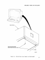
1. Gain access to the lower monitor area.
Cover Removal and Replacement procedure.
Refer to the Monitor - Bottom
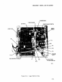
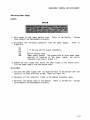
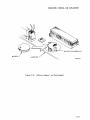
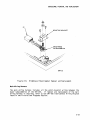
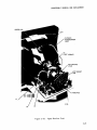
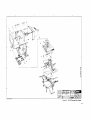
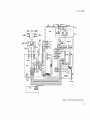
2. Disconnect the following connectors from the logic PCB.
2-6.
P5-1
P5-2
P6
P7
PI0
Refer to Figure
+5 Vdc from the power supply,
+12 Vdc from the power supply,
Vi deo PCB,
Brightness potentiometer,
Keyboard input.
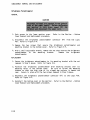
3. Remove the 8 screws that secu re the 1ogi c PCB (and the chass is ground
strap on the keyboard input jack) to the bottom cover.
from the bottom cover.
Lift the logic PCB
REPLACEMENT
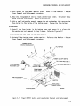
1. Pos it i on the 1ogi c PCB over its mount i ng holes in the bottom cover and
secure it in place with 8 screws. Be sure to also install the chassis
ground strap from the keyboard input jack.
Refer to Fi gure 2-6.
2. Reconnect all connectors listed in the Removal procedure above.
3. Reinstall the bottom cover on the monitor.
Cover Removal
2-12
an~
Replacement procedure.
Refer to the Monitor - Bottom