1
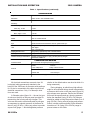
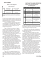
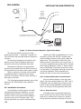
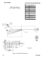
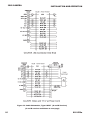
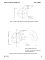
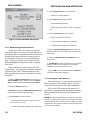
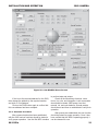
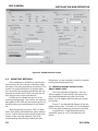
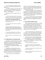
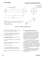
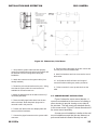
3960 SERIES
ENVIRONMENTAL CAMERA
INSTALLATION AND OPERATION MANUAL
Figure 1. High Performance Environmental Camera
Technical Manual 6X-1050a
Phone: 858-277-6700
Fax:
858-277-0221
[email protected]
www.cohu-cameras.com
Cohu Electronics • 3912 Calle Fortunada • San Diego, CA 92123-1827
August 11, 2005
3960 CAMERA
INSTALLATION AND OPERATION
LIST OF SECTIONS
SECTION
1.0
1.1
1.2
2.0
2.1
2.2
2.3
2.4
2.5
2.6
2.7
2.8
2.9
3.0
3.1
3.2
3.3
4.0
4.1
4.2
4.3
4.4
4.5
4.6
TITLE
GENERAL DESCRIPTION
Electrical Characteristics
Mechanical Characteristics
INSTALLATION
Unpacking and Receiving Inspection
Static Discharge Protection
Equipment Supplied
Equipment Required but Not Supplied
Cabling Requirements
Power Requirements
Mounting Requirements
Installation Procedure
Preparation for Shipment and Storage
Operation
Local Panel Control
Local Laptop PC Control
WinMPC Installation Setup
Mounting Methods
Pedestal Mount Installation - Small Base Plate
Large Base Plate Installation
Wall Mount Installation
Pole Mount Installation
Corner Mount Installation
Parapet Mount Installation
PAGE
1
1
1
7
7
8
9
9
10
15
15
17
17
18
18
18
18
22
22
24
24
25
25
25
FCC STATEMENT
This equipment has been tested and
found to comply with the limits for a
Class A Digital Device, pursuant to Part
15 of the FCC Rules. These limits are
designed to provide reasonble protection against harmful interference when
the equipment is operated in a commercial environment. This equipment
generates, uses, and can radiate radio
frequency energy and, if not installed
and used in accordance with the instruction manual, may cause harmful
interference to radio communications.
Operation of this equipment in a residential area is likely to cause harmful
interference in which case the user will
be required to correct the interference
at his own expense.
This device complies with Part 15 of the
FCC Rules. Operation is subjected to the
following two conditions: (1) this device
may not cause harmful interference and
(2) this device must accept any interference received, including interference
that may cause undesired operation.
LIST OF FIGURES
F IG U R E
T IT L E
PAG E
1
2
3
4
5
6
7
8
9
10
11
12
13
14
15
16
17
18
19
20
21
22
23
24
25
26
H ig h P e rfo rm a nc e E nviro nm e nta l C a m e ra
M o d e l N um b e r Inte rp re ta tio n D ia g ra m
O p tio na l L P E D D A d a p te r P la te
W a ll M o unt A rm
P o le M o unt
C o rne r M o unt
P a ra p e t M o unt
D im e ns io ns , M o d e l 3 9 6 0 C a m e ra
Typ ica l 2 3 2 /4 2 2 C o nve rte r
P ino ut D ia g ra m , 3 9 6 0 P ig ta il C o nne c to r
Inte rco nne ctio n D ia g ra m , Typ ic a l Te st S e tup
Te st C a b le , C TC -3 0 , 11 5 V a c
Te st C a b le , C TC -3 5 , 2 4 V a c
C a m e ra M o d ule R e a r P a ne l
M o d e l 9 3 0 0 L o c a l C o ntro l P a ne l
C a b le S c he m a tic , Typ e C A -2 9 7 A , B , C a nd D
D im e ns io ns , 3 9 6 0 Sta nd a rd B a se
D im e ns io ns , O p tio na l L a rg e B a s e
A b o ut W inM P C G U I S c re e n
C o hu W inM P C H o m e S c re e n
W inM P C S e tup S c re e n
D im e ns io ns , W a ll M o unt A rm
D im e ns io ns , P o le M o unt
D im e ns io ns , C o rne r M o unt
D im e ns io ns , P a ra p e t M o unt
Ins ta lle d P a ra p e t M o unt
1
6
7
7
7
7
7
9
11
11
12
13
14
15
15
16
19
19
20
21
22
24
25
26
27
27
2
CAUTION: Changes or modifications
to this device not expressly approved
by Cohu Electronics could void the
user’s authority to operate the device.
LIST OF TABLES
TABLE
TITLE
PAGE
1
2
3
4
5
6
7
Specifications
Mounting Configurations
Items Supplied
Items Required but Not Supplied
System Connectors
Pin Functions, 24 V ac Cable
Pin Functions, 115 V ac Cable
4
5
9
9
9
11
12
6X-1050a
3960 CAMERA
INSTALLATION AND OPERATION
1.0 GENERAL DESCRIPTION
This introduction briefly describes the overall
characteristics of the Model 3960 Camera/
Positioner (figure 1) related to its installation and
operation.
1.1 Electrical Characteristics
The 3960 provides a highly sensitive CCD
camera in a pressurized housing together with a
high performance pan/tilt positioner environmentally sealed from the environment..
All electrical connections are via 11 pins of a
single 16 pin connector on the end of a 34 inch
permanently attached “pigtail” cable. Table 1 lists
electrical and mechanical specifications for the
3960.
The 3960 is available with either NTSC or PAL
video output, depending on the model. Operating
power is either 24 V ac or 115 V ac — again depending on the model.
It has a day/night feature that increases sensitivity by reverting from color to monochrome output
in low light conditions. This feature can be made to
operate automatically or by manual control when
desired.
A model number interpretation diagram appears in figure 2. That diagram shows the various
basic configurations of the 3960.
1.1.1 Initial Setup Software
Win MPC Graphical User Interface (GUI)
software is available for setting the address and
performing field tests and setups for each camera/
positioner. This can be obtained at no cost from
either the cohu-cameras.com web site or by mail on
CD ROM for no cost. This test/setup software does
not control auxiliary equipment such as video
switchers, screen switchers, VCR’s, and such.
A separate manual is available for the Win
MPC software. The part number for that manual is
6X-1032. A suffix may be attached to this basic part
number to indicate the latest revision level of the
manual, but it can be downloaded or ordered using
the basic part number with the latest suffix.
To operate the 3960 in a system after setup by
WinMPC, either Cohu system software or some
6X-1050a
common third-party software can be used, depending on the requirements of the installation.
1.1.2 Cohu System Control Software
The 3960 can be operated by either the Cohu
Cams or NetCams software or by a variety of other
common third-party software protocols. Not all
features may be available with some of these thirdparty protocols. The protocols currently supported
are listed in both the specifications table and the
model number interpretation diagram.
The Cohu 3960 system control software is
designed to control the camera, the camera DSP
functions, lens functions, positioner pan/tilt functions, as well those of auxiliary equipment such as
video switchers, screen splitters, monitor selectors,
VCR’s, and other such equipment. The protocol and
message structure for the camera is common for all
cameras. No proprietary protocol and message
structure is used. Two versions of control software
are available:
Cams
The Cams protocol software is intended for
controlling multi-camera/positioner systems when
the Cohu MPC Master Control Panel is the central
control “intelligence” for the system. All control and
respond commands among the various equipment
in the system pass through the Master Control
Panel.
Net Cams
The Net Cams software is intended for controlling multi-camera/positioner systems when a Windows based PC is the central control “intelligence”
for the system. All control and respond commands
among the various equipment in the system pass
through the Net Cams Server.
1.1.3 Other Control Software/Protocols
During initial setup and testing of a 3960, the
Cohu WinMPC software is typically used for communications with the camera module and pan/tilt
positioner section of the 3960. This is typically done
with the software running on a windows based PC
at a test bench or at the installation site location..
Once the 3960 is ready to be released for service at
its installation site, a “working” protocol can be
selected for use in the control system. The currently
3
3960 CAMERA
INSTALLATION AND OPERATION
Table 1. Specifications
SYSTEM RELATED
Pan/Tilt Driver
Angular Travel
360° continuous pan range; -90 to +90 tilt range
P/T Speed (preset)
160° / sec
Pan Speed (manual)
0.1° to 80° sec
Tilt Speed (manual)
0.1° to 40° sec
Preset Accuracy
>0.1°
Power Input
89 V ac to 135 V ac; 120 V ac nominal, 60 Hz; per NEMA 2.1.2 Std TS2 for
traffic control systems
24 V ac optional
Power Consumption
70 W max with heaters
Power Transient Interruptions
NEMA 2.1.6 TS2
Weight
15 pounds (7 kg)
Environmental
-34° to 74° C (-29° to 165° F);
Conforms to NEMA 2.1.5.1 Standard TS2 for traffic control systems
Presets
64 preset positions
Title Generation
2 lines of 24 characters each for camera ID;
Preset ID, sector ID, privacy zone;
Low pressure alarm, temperature readout, pressure readout
Tours
8, each consisting of 32 presets with dwell time per preset per tour
Sectors
16 in the horizontal plane
Privacy Zones
8 programmable zones can be set for video blanking
Cloning
Positioner settings (presets, titles, etc.) can be stored to file for easy duplication
Inverted Operation
Can be mounted in an inverted position; software compensates for inversion
Vibration (less lens)
Sine vibration from 5 to 30 Hz, 1/2 g, 3 axis one hour
Shock
Up to 10 g's, 11 ms, in any axis under nonoperating conditions
Air Contaminants
Withstands exposure to sand, dust, fungus, and salt atmospheres per MIL-E5400T, paragraph 3.2.24.7, 3.2.24,8, and 3.2.24.9
Acoustical Noise
Can withstand environments >150 dB continuously to 30 minutes
EMI
FCC rules, part 15, subpart J, for class A devices
available protocols are listed in the Protocol Options
section of the Model Index shown in figure 2. Some
of these protocols may not support all functions of
the 3960.
mounted together with a high performance
positioner (pan/tilt unit) that is sealed from rain,
dust, dirt, and other undesirable contaminants. The
pan/tilt assembly is environmentally sealed but not
pressurized.
1.2 Mechanical Characteristics
The moulded housing provides an integral sun
shield over the camera module housing to prevent
heat build up that could result from direct sun light
on the camera module housing.
Dimensions are shown in figure 8. The 3960
consists of a sealed, pressurized camera module
4
6X-1050a
3960 CAMERA
INSTALLATION AND OPERATION
Table 1. Specifications (continued)
CAMERA RELATED
Imager
1/4-inch interline transfer color CCD
Resolution
NTSC or PAL: 470 horizontal tv lines
S/N Ratio
>50 dB
Sensitivity
Color, day, 1/60 sec
3.0 lux
Color, day, 1/4 sec
0.2 lux
Mono, night, 1/60 sec
0.3 lux
Mono, night, 1/4 sec
0.02 lux
Iris
Auto or manual override
Shutter
Auto or manual override
Focus
Auto or manual override
Sync
Interal ac linelock with remote line lock for system-wide sync
Lens
Intergal 23X optical (3.6 to 82.8 mm)
10X digital
Auto / manual focus
Day/Night Switch Over
Day (color) / night (mono), auto or manual control
Humidity
100 percent relative humidity
Camera Housing Pressurization
Sealed and pressurized to 5 psig (35 kPa) with dry nitrogen
Rated IP67, NEMA 4X
COMMUNICATIONS RELATED
Communications
RS-422 serial with digital positioning feedback
NTCIP
Protocol
Firmware
Cohu multiprotocol
Philips / Bosch RS-232
Javelin
Ultrak
Kalatel / GE
Vicon Surveyor
Stored in flash memory; uploaded via serial port
All electrical connections are made via a 34inch pigtail cable permanently attached to the
bottom of the 3960 base. A connector with positions
for 16 pins is connected to this cable to provide all
electrical connections. Only 11 of these pin locations are used.
A Schrader valve (figure 14 — the car tire type
air valve on the left) on the rear panel provides for
pressurizing the housing with dry nitrogen. This
valve can be used to occasionally add dry nitrogen
as necessary to maintain pressure in the barrel at
about 5 psig (35 kPa). (Note: psig refers to pounds
square inch gauge — which designates pressure
6X-1050a
Pelco D
relative to the altitude above sea level at which it is
being measured.)
During shipping, at which times high altitude
might be encountered during aircraft transportation,
a pressure relief valve on the rear panel (figure 14)
may release some pressure. Back at low altitudes
this would be experienced as a housing pressure
below the standard 5 psig (35 kPa). Dry nitrogen
should be added to bring the pressure back up to 5
psig (35 kPa). During normal purging and pressurization, internal pressure should not be allowed to
rise above a 5 to 8 psig (35 to 55 kPa) range to
prevent stress on the seals.
5
3960 CAMERA
INSTALLATION AND OPERATION
396 x — x x x x
SERIES
DSP Color Camera
Pressurized Housing
Sunshield
xxxx
ACCESSORIES
VIDEO
FORMAT
Not
Assigned
3 NTSC
7 PAL
0 None
MOUNT
PROTOCOL
OPTIONS
POWER
4 24 V ac input power
5 115 V ac input power
1
PEDD
LPED
WALL
POLE
CONR
PARP
Cohu
(Contact Cohu for
other available
protocols)
Pedestal - Small Base
Pedestal, Large Base
Wall Mount
Pole Mount
Corner Mount
Parapet Mount
Figure 2. Model Number Interpretation Diagram
Table 2. Mounting Configurations
MOUNT
DESIGNATION
MOUNT
DESCRIPTION
3960
CAMERA /
POSITIONER
PEDD
pedestal,
small base
•
LPEDD
pedestal,
large base
•
WALL
wall
•
•
POLE
pole
•
•
CONR
corner
•
•
PARP
parapet
•
•
LARGE
BASE
ARM
ASSEMBLY
POLE
MOUNT
ASSEMBLY
CORNER
MOUNT
ASSEMBLY
PARAPET
MOUNT
ASSEMBLY
•
•
•
•
NOTE: Dot ( • ) designates an item supplied for each mounting configuration. Example: a PARP (parapet )
mount configuration consists of the 3960 camera/positioner, an arm assembly and a parapet mount assembly.
Note that the LPEDD (large pedestal base) does not mount to any of the accessories listed in this table. This
adapter plate has hole patterns typically used by other accessory mounts used with cameras.
6
6X-1050a
3960 CAMERA
INSTALLATION AND OPERATION
Figure 3. Optional LPEDD Adapter Plate
Figure 7. Parapet Mount
Figure 4. Wall Mount Arm
The pressure relief valve should be lifted off its
seat during purging of the camera. This aids in the
flow of gas through the housing while purging
moisture laden air from inside.
The mounting base for the 3960 has a fourhole pattern for attachment to a pedestal, mounting
arm, or other suitable base. High quality (grade
316) stainless steel bolts and lock washers should
be used. An additional add-on base plate is available to provide additional hole patterns on a larger
diameter.
Figure 5. Pole Mount
A 3960 can be mounted in any one of six
mechanical configurations depending on the mounting accessories supplied. The model number
defines the mounting equipment supplied as part of
the 3960. Table 2 shows the mounting items supplied for each of the mounting configurations available with a 3960.
2.0 INSTALLATION
This section covers the general requirements
of installing the 3960 including cabling, power
requirements, and pressurization considerations. In
addition to the actual installation requirements, this
section covers a number of other items including
static discharge protection and proper shipping and
handling of the 3960.
Figure 6. Corner Mount
6X-1050a
Section 4 at the rear of this manual covers the
various mounting brackets, their dimensions, and
7
3960 CAMERA
general installation requirements of bolting the 3960
in place. . A prime consideration will be routing of
the system cable to a 3960. This must be planned
for during the initial consideration of an installation
location.
These mounts should be installed only by
qualified installers thoroughly familiar with the
various code requirements and industry standard
best practices for an installation.
2.1 Unpacking and Receiving Inspection
This item was thoroughly tested and carefully
packed in the factory. Upon acceptance by the
carrier, they assume responsibility for its safe
arrival. Should you receive this item in a damaged
condition, apparent or concealed, a claim for damage must be made to the carrier.
If a visual inspection shows damage upon
receipt of this shipment, it must be noted on the
freight bill or express receipt and the notation
signed by the carrier's agent. Failure to do this can
result in the carrier refusing to honor the claim.
When the damage is not apparent until the unit
is unpacked, a claim for concealed damage must be
made. Make a mail or phone request to the carrier
for inspection immediately upon discovery of the
concealed damage. Keep all cartons and packing
materials.
INSTALLATION AND OPERATION
Components used in modern electronic equipment, especially solid state devices, are susceptible
to damage from static discharge. The relative susceptibility to damage for semiconductors varies from
low with TTL to high with CMOS. Most other semiconductors fall between TTL and CMOS in susceptibility to static discharge. As a minimum, therefore,
observe the following practices when working inside
this or any other electronic equipment:
1. Use conductive sheet stock on the work bench
surface.
2. Connect the sheet stock to ground through a 1
megohm or greater value resistor.
3. Use a wrist strap connected to ground through a 1
megohm or greater value resistor when working at the
bench.
4. Maintain relative humidity of the room above 30
percent. This may require a room humidifier. Working
on circuits with relative humidity below 30 percent
requires extraordinary procedures not listed here.
5. Use antistatic bags to store and transport an
exposed chassis, circuit boards, and components.
Use new antistatic bags. Old, used bags lose their
static protection properties.
To return the product to the factory for service,
please contact the Customer Service Department
for a Return Authorization (RA) Number.
This list serves as a reminder of the minimum
acceptable practices. Be sure that all static discharge devices at the work bench are properly
installed and maintained. Standard grounding mats
and wrist straps purchased for use at work benches
are supplied with leads having current limiting
resistors for safety. Never substitute with a grounding lead not having the resistor.
2.2 Static Discharge Protection
2.3 Equipment Supplied
Procedures in this manual do not require entry
into the housing of the 3960. But in the event that a
disassembled 3960 is being handled, the following
precautions should be followed:
The assembly consists of a pressurized camera
housing and environmentally sealed positioner (pan
and tilt) assembly. The housing is fitted with an
integral sun shield assembly that covers the camera
module housing. This sun shield minimizes heat
buildup inside the camera by shielding it from the
direct rays of the sun. Table 3 lists the items supplied.
Since shipping damage is the carrier's responsibility, the carrier will furnish you with an inspection
report and the necessary forms for filing the concealed-damage claim.
CAUTION
This 3960 contains sensitive devices that can be damaged by static discharge. Use appropriate static control methods when working inside the 3960.
8
A connector is supplied to mate with the 3960
pigtail connector. This connector is to be wired to the
system interconnection cable. See table 3.
6X-1050a
3960 CAMERA
INSTALLATION AND OPERATION
Figure 8. Dimensions, Model 3960
If the optional large mounting base is ordered
(LPEDD option) it will be supplied with four 1/4-20 x
3/4 mounting screws. If the plate is factory installed
these screws will be used for that installation and
not supplied as loose parts.
2.4 Equipment Required but Not Supplied
Table 4 is a list of equipment that may required
to install and make use of the 3960. As a minimum
the 3960 requires a source of operating power, a
monitor on which to view the scene, an interconnection cable, and a computer running Graphical User
Interface (GUI) software for control of the 3960 if
this is desired. Programming the optional ID generator messages requires a GUI software such as
the Cohu WinMPC setup and maintenance software. This is available at no cost from Cohu Electronics:
www.cohu-cameras.com
During maintenance and setup operations
using either a laptop or desktop PC it is likely that a
6X-1050a
422/232 converter will be required. Most PC’s have
only a serial RS-232 communications port.
Installing the 3960 will also require high quality
stainless steel (preferably grade 316) mounting
bolts and a platform of some type on which to
mount it. Gasket materials and sealing compounds
may also be required to provide waterproofing of
mounting holes in structures.
For installing with a pole mount (POLE option),
a tensioning tool is available to snug up the stainless steel straps holding the mount to the pole.
2.5 Cabling Requirements
All electrical connections for the 3960 route
through a permanently attached 34-inch cable. This
cable is attached to the bottom of the 3960 housing.
A 16 pin connector is attached to the free-hanging
end of the cable.
A mating connector is supplied for making
system interconnections. This connector should not
be attached to the system cable until it is known that
9
3960 CAMERA
INSTALLATION AND OPERATION
Table 3. Items Supplied
Table 4. Item Typically Required
But Not Supplied
IT E M S S U P P L IE D
IT E M S T YP ICAL LY RE QUIRE D BUT NOT S UP P L IE D
IT E M
1
DE S CRIP T ION
Co h u P a r t Nu m b e r
C onnector B ody
1310307-009
B ackshell
1310307-103
S ockets (11 each)
1310308-002
T hese item s m ake up a connector that m ates with the cam era pigtail
connector. N ote that while this connector is capable of interfacing 16
sockets to 16 pins on the 3960 connector, only 11 of these positions
are used.
the cable can be routed through any narrow places
(such as conduit) with the connector attached. Note
that bends and turns in a routing can sometimes be
difficult with an attached connector.
Figure 11 shows a typical test setup interconnection diagram for the 3960 using a laptop PC
running WinMPC as the control point. Test cables
CTC-30 (115 V ac) and CTC-35 (24 V ac) are
available for this purpose.
Figure 16 shows four versions of a typical
system interconnection cable. Only 11 of the pin
locations on the connector body are used for the
two versions of the 3960 (24 V ac and 115 V ac).
Note that different pins are used for the power
input. Pin 12 is used for the line (hot) lead for 115 V
ac and pin 16 for one lead of 24 V ac.
Always pre-plan all system cabling before
starting an installation. Before a 3960 is bolted in
place, the system cable must be available to attach
to the pigtail cable at the mounting location.
Figure 16A is an assembly diagram for the
cable used between the 3960 and a typical junction
box having a terminal strip for all connections. This
cable has five stripped wire leads for the data
connections and also stripped leads for the ac
power plug BNC video connector.
Figure 16B is the assembly diagram for the
cable used between a 3960 and a typical junction
box. This cable has an ac power plug, BNC video
connector, and stripped leads for data connections
at the junction box.
Figure 16C is an assembly diagram for the
cable used between the 3960 and a junction box
having RS-232 data communications available. This
cable has an RS-232 to RS-422 converter wired in
10
IT E M
Descriptio n
Chara cteristics
1
S upport base
Hole pattern to match 3960
2
C able
P ower, RS -422, 75 ohm coax
3
S ource of power
24 V ac or 115 V ac,
as required
4
V ideo monitor
75 ohm, NTS C or PA L,
as required
5
P C , laptop or other
RS -232 serial output
6
S erial converter
232 / 422 conversion
7
Installation/setup software
C ohu W in MP C
(available at no cost from C ohu)
8
S ystem C ontrol S oftware
C ohu C ams, C ohu Net C ams
or various other common
software depending on the
installation
9
Tensioning tool (for pole mount
installation only)
C ohu part no. 7411411-001
10
Local C ontrol P anel (optional)
C ohu Model 9300
for data communications with the RS-232 sources.
This cable also has an ac power plug and the BNC
video connector like the previous cable.
Figure 16D shows the cable wiring between
the 3960 and an optional Cohu Model 9300 Local
Control Panel (figure 15).
This panel is typically located in a nearby
equipment cabinet. It is used when an on-site local
control panel is desired for setup and maintenance
operations. This panel typically is installed in a
weatherproof cabinet located near the 3960 installation location. This optional panel can control
some functions of the 3960 without use of a local
laptop PC running WinMPC.
But a front panel BNC connector on the 9300
provides for connecting the RS-232 serial port of a
laptop PC to communicate with the 3960 using
WinMPC. When a 9300 local control panel is
installed at the 3960 site location, it becomes the
site address for the 3960. Any address programmed into the 3960 is not seen by the system.
Figure 12 is the assembly diagram for a test/
setup cable intended for use during setup and
maintenance operations of a 115 V ac 3960. This
cable is intended for use with the RS-232 output of
a laptop or other type PC; thus, an RS-232 to RS422 converter is required to communicate with the
3960 — which uses only RS-422.
6X-1050a
3960 CAMERA
INSTALLATION AND OPERATION
Table 5. 3960 Connector & Mating Cable Plug
DE S CRIP T ION
CAME RA P IGTAIL
CONNECTOR
MAT ING S YS TE M
CABLE P LUG
C onnector Housing
1310306-010
C ohu 1310307-009
Backshell
1310307-103
Cohu 1310307-103
Contacts (11 each)
Pins
1310308-001
Sockets
C ohu 1310308-002
One end of cam era 34-inch pigtail cable is perm anently attached to
base of cam era and the other end is term inated with the pigtail
connector.
Figure 13 is a version of the cable to use with
a 3960 operating from 24 V ac.
Figure 9 shows a typical 232/422 converter.
The terminal labels used on various models of
these converters differ, so it is important to read the
literature accompanying the converter being used.
Handshake is not used in this application. It is
recommended that a B & B model 422PP9TB
converter be used. This converter is available from
Cohu Electronics as part number 3010100-001.
Note that when a Local Control Panel is being
used this test/setup cable and 232/422 converter
are not required. The Panel has an RS-232 D9
connector on its front panel. The system cable from
the central control station connects to the rear of
this panel. Communications passes through the
panel to another rear panel connector to which the
3960 pigtail connector connects.
Table 6 is a list of pin functions for the connector used with a 3960 that operates from 115 V ac.
Table 7 is for the 24 V ac version of a 3960 cable.
2.6 Power Requirements
Two versions of the 3960 are available: The
model 3964 operates from 24 V ac; the 3965
operates from 115 V ac.
(Available from Cohu as Part Number 3010100-001)
POWER
MAY BE REQUIRED
WITH CA-297C CABLE
Model 422PP9TB
xR
x+
R
Tx
+
Tx
B&B Electronics
707 Dayton Road
PO Box 1040
Ottawa IL 61350
422
232
B
&B
CONVERTER
TD(A)
TD(B)
RD(A)
RD(B)
GND
+12V
D9
FEMALE
[email protected]
www.bb-elec.com
TO 3960
Figure 9. Typical 232/422 Converter
6X-1050a
2
1
3
7
4
8
5
6
9 10
11 12 13 14
15 16
Mating View of Connector on Cable
Attached to Camera Base
Figure 10. Pin Location Diagram,
3960 Pigtail Connector
The maximum power requirements is 70 watts
which occurs with heaters on during cold conditions.
The line (hot) lead of 115 V ac power uses pin
12 of the connector. Neutral connects through pin
13. Ac ground is pin 15.
On a 24 V ac version of the 3960, power is
applied to pins 13 and 16.
2.7 Mounting Requirements
The dimensions shown in figure 8 related to
mounting the 3960. The 3960 can be optioned for
six different mounting configurations:
1. Direct mounting to the base plate on the 3960.
See section 4.1 for details about this standard mounting base.
2. Mounting to a second, larger circular mounting
base which then mounts to a suitable surface. See
section 4.2 for mounting with this option.
3. Wall Mount Arm (for direct mounting to a suitable
wall surface or for mounting to items 4, 5, or 6 below)
4. Pole Mount. Clamps to a pole using stainless steel
straps. The wall mount arm then attaches to this pole
mount.
5. Corner Mount. Bolts to the corner of a building or
other structure. The wall mount arm then attaches to
this corner mount.
6. Parapet Mount. Bolts to the inside of a parapet on
a roof of a building or other structure. The wall mount
arm then attaches to the parapet.
11
3960 CAMERA
INSTALLATION AND OPERATION
Connect
Either
115 V ac
or
24 V ac
(Depends on
Camera Model)
3960
115 V ac
24 V ac
Picture
Monitor
75 Ohm
Coax
Terminated 75 Ohms
Use Test Cable CTC-30 for 115 V ac use
Use Test Cable CTC-35 for 24 V ac use
Converter
422 232
Twisted
Data Pairs
Win
MPC
Direct Plug-in
to Laptop
Serial Port
Figure 11. Interconnection Diagram, Typical Test Setup
All mounting hardware should be of high
quality stainless steel — preferably of grade 316.
This will ensure high strength fasteners resistent to
corrosion.
All mounting hole patterns discussed in this
section are four holes 90 degrees apart at the
diameters noted unless otherwise mentioned.
Mechanically indexing to a home position
should not be required since the 3960 will return to
the last position at shut down when turned on again.
Refer to section 4 at the back of this manual
for additional details concerning these various
methods of mounting a 3960 to a pole, building, or
other type of structure.
The following paragraphs describe some of the
features of the 3960 related to the installation
process.
2.8 Installation Procedure
It is important to carefully plan for all cable
routing before starting an installation. In some
situations cable will have to be pulled through
conduit or other narrow places before adding a
connector to the end of a system cable. Any
through-wall holes may require weatherproofing.
12
Installing the 3960 is straightforward. It is only
necessary to mount the 3960 to a suitable base,
mate the cable connector to the system cable and
apply power. This assumes the other end of the
cable is properly connected to a source of power, a
tv monitor, a graphical user interface (GUI), and any
other required equipment. Figure 11 shows a basic
setup of the 3960 in a test setup as would be used
in a test facility. This diagram should give some idea
of a typical installation. Each installation site,
though, will have its own unique requirements.
2.8.1 Camera Module Rear Panel Features
Only two features appear on the rear panel
(figure 14) of the camera module of a 3960. One is
a Schrader valve for applying dry nitrogen to the
interior of the Camera assembly housing and the
other is a 20 psig (138 kPa) pressure relief valve.
2.8.1.1 Schrader Valve
A Schrader valve is functionally identical to
those used for car tires. But this valve should be
used only to introduce dry nitrogen to a camera.
During assembly cameras are purged of normal
6X-1050a
3960 CAMERA
INSTALLATION AND OPERATION
PIN
Table 6. Pin Functions,
115 V ac Camera Connector
FUNCTION
1
video, 75 ohm
2
ground, video
3
ground, data
4
TX-
5
TX+
6
RX+
7
RX-
8
nc
9
nc
10
nc
11
nc
12
115 V ac line (high/hot)
13
115 V ac neutral (low)
14
shield, overall cable
15
ground, ac
16
nc
nc designates not connected (not used)
Figure 12. Test Cable, CTC-30, 115 V ac
6X-1050a
13
3960 CAMERA
INSTALLATION AND OPERATION
PIN
Table 7. Pin Functions,
24 V ac Camera Connector
FUNCTION
1
video, 75 ohm
2
ground, video
3
ground, data
4
TX-
5
TX+
6
RX+
7
RX-
8
nc
9
nc
10
nc
11
nc
12
nc
13
24 V ac low
14
shield, overall cable
15
ground, ac
16
24 V ac high
nc designates not connected (not used)
Figure 13. Test Cable, CTC-35, 24 V ac
14
6X-1050a
3960 CAMERA
INSTALLATION AND OPERATION
camera housing. If the camera module should loose
some dry nitrogen during high altitude transportation (as indicated by a pressure reading below
about 5 psig) then some additional dry nitrogen may
be added to replenish the lost nitrogen.
This valve should be manually lifted off its seat
or pushed slightly to the side when it is desired to
flow dry nitrogen through the camera to purge
moisture laden atmospheric air from the camera
module.
Regularly applying pressure above 5 to 8 psig
(35 to 55 kPa) may cause seals to weaken and
leak.
Figure 14. Camera Module Rear Panel
room air (which typically has a high relative humidity) by flowing dry nitrogen into the Schrader valve
and out the pressure relief valve. This relief valve
should be held open to aid in the flow of nitrogen
out of the camera.
This purging process removes moist room air
from inside the camera and provides an internal
relative humidity of five percent or less. A camera is
typically pressurized to 5 psig (34 kPa). Pressure
can be allowed to go below this — even down to
one or two pounds so long as the pressure does not
ever become zero. An occasional recharge of dry
nitrogen can be used to maintain pressure near 5
psig (34 kPa). If pressure continually drops it is an
indication of a slow leak. These pressure references are gauge pressures (psig). They are relative
to the altitude above sea level at which they are
being measured.
2.8.2 16-pin Connector
This connector is attached to the 34 inch (86
cm) long cable that is permanently attached to the
base of the 3960. Table 6 lists pin functions for a
115 V ac version of the 3960 and table 7 lists
functions for a 24 V ac version. Note that five of the
pins are not used — although different pins are
used to apply the line (hot) lead of 115 V ac and
one line of the 24 V ac power. The camera model
number identifies whether it is configured for 115 V
ac or 24 V ac operation.
Figure 10 is the pin location diagram of this
connector. It is a view from the mating side of the
connector. This view is identical to the wiring view of
a mating connector (supplied) for the system cable
that plugs into this 3960 connector.
The connector supplied for the system cable
should not be installed until it is verified that the
cable can be pulled through any conduit or other
restricted passage on its way to the mounting
location of the 3960.
2.8.1.2 Pressure Relief Valve
The pressure relief valve opens at about 20
psig (138 kPa). This relief pressure allows the 3960
to be taken to high altitude during transportation
without excess bleed off of dry nitrogen from the
2.9 Preparation for Shipment and Storage
Maintain the 3960 storage environment within
a range of -34 to 74 °C (-29 to 165 °F).
Figure 15. Model 9300 Local Control Panel (Optional Installation Equipment)
6X-1050a
15
3960 CAMERA
INSTALLATION AND OPERATION
Figure 16. Cable Schematics, Type CA-297 (A and B Versions)
(C and D versions and Notes on next page)
16
6X-1050a
3960 CAMERA
INSTALLATION AND OPERATION
CA-295
CONNECTOR
ACCESSORY ACCESSORY
(MAIN)
A
1310307-009
1310307-103
(clamp)
B
1310307-009
1310307-103
(clamp)
C
1310307-009
1310307-103
(clamp)
D
1310307-009
1310307-103
(clamp)
1310308-002
(6-contact)
1310308-008
(5-contact)
1310308-002
(6-contact)
1310308-008
(5-contact)
1310308-002
(6-contact)
1310308-008
(5-contact)
1310308-002
(6-contact)
1310308-008
(5-contact)
CONNECTOR ACCESSORY
RS-232 TO RS-422
CONVERTER
—
—
—
1310212-004
(BNC)
—
—
1310212-004
(BNC)
—
—
1310306-010
(Amp)
1310307-103
(clamp)
1310308-001
(6-contact)
1310308-007 (5-contact)
Figure 16. Cable Schematics, Type CA-297 (C and D Versions)
6X-1050a
17
3960 CAMERA
INSTALLATION AND OPERATION
For shipment, package with enough foam
padding or other packing material to prevent damage that can occur during shipping. The original
shipping carton is a good container if it has not
been damaged or subjected to excessive moisture.
For shipping to the factory by Common Carrier, use
the following address:
Cohu Electronics
3912 Calle Fortunada
San Diego, CA 92123-1827
Please contact the Customer Service Department for a Return Authorization (RA) number before
sending any shipments to the factory:
central control facility, it is possible to connect a tv
monitor to the Panel and control basic functions of
the 3960. A laptop PC running Windows would
connect to the RS-232 BNC connector on the front
of the panel for communications with the 3960. The
LOCAL/REMOTE switch on the 9300 must be set to
LOCAL to perform this local control.
The model 9300 local control panel can be
programmed for a site address. That address is
used for the site address — not the address of the
3960.
The system cable plugs into the 9300 and a
second cable then interconnects between the 9300
and the 3960. The 9300 becomes the site address.
3.2 Local Laptop PC Control
[email protected]
or
858-277-6700 extension 261
Prominently display the RA number on the
outside of the shipping container(s) and on paperwork contained inside. Give a brief description of
why the equipment is being returned and list the
symptoms of any problems being experienced with
the equipment.
3.0 OPERATION
Several GUI interfaces are available for use
with the 3960:
1. Win MPC (figure 19) is used to control a single
3960 during installation or maintenance operations.
This can be done either at a central shop facility or at
the site location of the 3960.
2. CAMS is used to control multiple 3960 systems
when an MPC Master Control Panel is being used as
the central control point.
3. NET Cams is used to control systems with multiple
3960 when the central control is a Net Cams Server.
This section of the manual describes use of
the WinMPC maintenance and setup GUI software.
3.1 Local Panel Control
If the 3960 has been connected through a
nearby Model 9300 Local Control Panel back to the
18
A local laptop PC running Win MPC software
can be used to connect to the 3960 and control a
full range of functions including the setting of its
address. This laptop can either connect through an
RS-232 connector on the front of an optional Local
Control Panel or it can connect directly to the 3960
RS-422 cable — in which case the RS-232 to RS422 converter is required.
3.3 WinMPC Installation Setup
Figure 20 is the home window of WinMPC. It is
from this window that other windows can be accessed. When Win MPC is used to set up the
3960, it must be isolated from all other 3960s (or
other addressable equipment) in the system. This
generally is no problem since the 3960 setup is
performed either at a test bench location or at the
actual 3960 site itself. If the address setting function of Win MPC were to be sent to multiple 3960s
they would all have identical addresses programmed into their memory. Since all addressable
equipment in a system must have a unique address, this would result in an inoperative system.
Note: A separate operator’s manual is available for
the WinMPC software (Cohu manual No. 6X-1032.)
The information here describes initial use of
WinMPC for use with the 3960. Additional information is available in the WinMPC manual. Also be
aware that the software may be updated more often
than this manual. Slight differences may be noted
with the version of WinMPC that is currently available for the 3960.
6X-1050a
INSTALLATION AND OPERATION
3960 CAMERA
Figure 17. Dimensions, 3960 Standard Base (Permanent Part of 3960)
Fastens to Standard Base Above
Four 1/4-20 x 3/4 Flathead Screws Included
Cohu P.N. 0310010-093
Figure 18. Dimensions, Optional Large Base (attaches to base above)
6X-1050a
19
3960 CAMERA
INSTALLATION AND OPERATION
c. At the Comm Mode area of the Window:
i. Select PC to MPC Receiver
d. At the Camera area of the window:
i. Select Day/Night (default)
ii. Under Video select NTSC or PAL, as appropriate
e. Under the Pan/Tilt area of the window:
i. Select Var Speed P/T (default)
Figure 19. About WinMPC GUI Screen
ii. Select a Max Pan Speed of 15 (default)
iii. Select a Max Tilt Speed of 15 (default)
3.3.1 Establishing Communications
Since each 3960 in the system (or optional
local control panel) must have a unique address, it
is probably best to set all addresses at a test bench
located at the central distribution location prior to
sending each of them out to the field installation
sites. Providing a central control location for all
address assignments may ensure that no duplications occur.
Before the address can be set or any other
setups made, it is necessary to establish communications with the 3960. The home window of Win
MPC provides the initial setup selections. Proceed
as follows:
1. Under the Special Functions menu area of the
Cohu - WinMPC (home) window, click on Camera
Setup. A new window should appear titled Setup.
2. Under the Setup window set:
a. Receiver selections to iDome/iView/IView2 (this
is the series to which the 3960 belongs)
b. At the Comm area of the window:
i. Select the Port being used on the PC (Com1,
Com 2, Com 3, Com 4)
ii. Select a Baud Rate of 9600 (Click “Set Baud”)
20
f. Under the Pan/Tilt Background area select any
desired image type for the center pan/tilt area of the
home page.
g. Under the Set Elevation (0-10,000 ft) area of
the window:
h. Set Elevation for the elevation above sea level at
which the 3960 is to be installed. (This provides
calibration for the low pressure circuit)
i. Click on OK to exit the Setup window (or Cancel to
exit without making any changes).
3.3.2 Setting the 3960 Address
After initial setup, it is a good idea to allow Win
MPC to search for the existing address. This will
verify that communications has been established.
Click on the FIND button at the upper left of
the window. A pop-up window will appear while Win
MPC searches for all allowable 3960 addresses (1
to 223).
NOTE: Win MPC is intended to be connected to one 3960
at a time. If it were to be connected into a system of 3960s
and the Address Set Function used, all 3960s (or other
equipment) in the system would have their identifications
set to the same address.
6X-1050a
3960 CAMERA
INSTALLATION AND OPERATION
Figure 20. Cohu WinMPC Home Screen
to perform tests and setups.
If this is not the required address for this 3960,
then change the address to the required number
and click on “Set Address.”
Click on the FIND button again to confirm that
this new address has been accepted.
3.3.3 Checkout Procedure
After communications has been established
with the 3960 various functions should be tested to
verify proper operation. Use the Win MPC interface
6X-1050a
Check all the Momentary functions: zoom,
focus, iris, color, and integration. Latch commands
also should be tested: 3960 power, lens fast,
manual iris, and color balance. Several presets
should be set and then re-established to verify their
operation.
After presets are established, the tour function
should be tested for proper operation. Once it has
been verified that the 3960 is operating properly it
can be released for use.
21
3960 CAMERA
INSTALLATION AND OPERATION
Figure 21. WinMPC Setup Screen
4.0
MOUNTING METHODS
Since installation of a 3960 may require that it
be mounted to any of a variety of structures, different types of mounting assemblies are required. This
section is a generic description of typical installations for each of the mounting assemblies that can
be optioned with the 3960. Each mounting site will
likely have its own unique requirements.
A 3960 can be ordered with any one of six
mounting arrangements. Two of these are related to
base plates for the 3960 and the remaining four are
actual mounting arms and brackets for an installation.
Before preparing to mount a 3960 it is important to have either pre-installed the system cable or
to have verified that the cable can be routed to the
location of the mounting assembly. This often
requires pulling cable through conduit and other
22
tight places. It is also necessary to plan for weatherproofing any through-wall holes
4.1 PEDESTAL MOUNT INSTALLATION SMALL BASE PLATE
This is the simplest configuration. Only the
3960 is supplied. It bolts directly onto the top of a
site-supplied pedestal having the correct hole
pattern or to an adapter plate providing the proper
hole pattern.
Figure 17 is a dimensional diagram of the hole
pattern on this plate. This base is a 6-inch diameter
0.375-inch plate permanently mounted to the 3960.
It provides four 1/4-20 threaded bolt holes
spaced 90° apart on a 4.75-inch diameter hole
pattern.
6X-1050a
INSTALLATION AND OPERATION
The 1/4-20 fasteners threaded into these
holes must not protrude through the base more
than 0.1 inch.
The 3960 can be directly mounted to the wall
mount arm (section 4.3 below) or to any other
base that matches the 4.75-inch diameter hole
pattern on the 3960 Base.
Proceed as follows to install the 3960 on a
pedestal:
1. Route the cable pigtail down into the pedestal.
This cable should be secured by a strain relief and
not allowed to hang free within the pedestal if there
is a long cable run hanging underneath. (If an
access plate is not available at the top of the
pedestal, the system cable must first be connected
to the pigtail connector.)
2. Bolt the 3960 to the pedestal using stainless
steel hardware.
3. Attach the pigtail connector to the system
connector. This often is done through a removable
access plate. Be sure these cables are secured
with a strain relief so that they do not hang free with
long cable runs.
4. Verify that the 3960 will have a full range of
movement without striking any nearby structure.
5. Refer to section 3 to set up and check out the
3960.
3960 CAMERA
pattern. If site-supplied flathead screws are used
they must not protrude through the standard base
plate by more than 0.1 inch. More than this would
jam into the 3960 housing.
This optional base has two four-hole patterns
for mounting to a pedestal or other type mount. One
pattern is on a 7-inch diameter and the other on a
7.25-inch diameter pattern. Holes on each pattern
are spaced 90° from each other. These patterns are
offset from each other by 22.72°.
All support mounting holes are 0.380 diameter.
They are intended for 3/8-inch hardware. Use high
quality fasteners made from grade 316 stainless
steel.
4.3 WALL MOUNT INSTALLATION
Figure 4 shows the wall mount arm. For a wallmount installation, the support arm bolts directly to
a wall. An adapter plate on the end of the arm
matches the hole pattern of a 3960 base. The 3960
is placed on the arm and is then bolted to it. This
arm is also used with the remaining three mounting
methods (pole, corner, and parapet).
Figure 22 shows dimensions of the basic wall
mount arm. The 0.38-inch diameter holes (slotted)
are suitable for use with 5/16-inch mounting hardware. All mounting hardware should be of high
quality and made from grade 316 stainless steel.
This diagram does not show the adapter plate
on the end of the arm to which the 3960 fastens.
4.2 LARGE BASE PLATE INSTALLATION
This plate is not required for any of the Cohu
supplied mounting arms and brackets covered in
this manual. It is an optional 8.5 inch diameter
base plate that attaches to the 3960 base plate to
provide additional mounting hole options.
Figure 18 is the dimensional diagram of this
optional base.
It attaches to four threaded holes on the
3960 standard base with flathead 1/4-20 x 3/4
mounting screws. Use of flathead screws maintains the entire surface of the adapter plate flat for
placing on an existing on-site mounting base
This adapter plate has four 1/4-20 threaded
holes on a 4.75-inch diameter hole pattern to match
the baseplate of the 3960.
The basic installation procedure is:
1. Verify that the system cable is accessible for
connection to the 3960 pigtail cable at the mounting
location.
2. Install a connector to the end of the system cable
(if not already installed).
3. Attach the adapter plate to the wall mount arm (if
not already attached).
These holes are on the 4.750 diameter
6X-1050a
23
3960 CAMERA
INSTALLATION AND OPERATION
Figure 22. Dimensions, Wall Mount Arm
4. Install a weather tight gasket between the arm and
the surface of the wall (if this is required).
5. Route the 3960 pigtail cable down into the arm
and out the back. Note that plastic plugs can be
removed to aid in this process.
6. Position the 3960 on the arm adapter plate and
secure it with the hardware.
7. Connect the pigtail connector to the system cable
connector.
8. Pull the system cable back into place so the are
can be positioned to the wall.
9. Bolt the Arm to the wall.
10. Verify that the 3960 will have a full range of
movement without striking any nearby structures.
11. Refer to section 3 to set up and check out the
3960.
24
4.4 POLE MOUNT INSTALLATION
Figure 5 shows the pole mount bracket.
This mounting arrangement provides a pole
mount bracket to which the wall mount arm
attaches. The bracket attaches to the pole
using stainless steel straps. A tensioning tool
will be required to secure the stainless steel
straps to the pole (Cohu tool, part number
7411411-001). See item 8 in table 4
Provisions must be made for routing the
system cable up to the 3960 location on the
pole. Cables often route up through the pole
and exit at an access port near where the pole
mount bracket will attach. Provisions may have
to be made to support the cable inside the pole
so that the full cable weight is not supported
solely at the top.
A pole mount installation is similar to the
wall mount installation except that the arm
fastens to a pole mount bracket instead of
directly to a wall.
6X-1050a
3960 CAMERA
INSTALLATION AND OPERATION
Figure 23. Dimensions, Pole Mount
1. Verify that the system cable has been properly
routed to a location where the pole-mount bracket will
be attached. Plan the routing before doing any
installation.
2. Attach the connector to the system cable (if not
already installed).
3. Fasten the pole-mount bracket to the pole – being
sure that the system cable is routed so that it is
available for the wall-mount arm.
4. Attach the adapter plate to the wall mount arm (if
not already attached).
5. Route the 3960 pigtail cable down into the arm
and out the back. Note that plastic plugs can be
removed to aid in this process.
6. Position the 3960 on the arm adapter plate and
secure it with the hardware.
7. Connect the pigtail connector to the system cable
connector.
6X-1050a
8. Pull the system cable back so the arm can be slid
over the pole mount threaded studs..
9. Install lock washers and nuts to secure the arm to
the bracket..
10. Verify that the 3960 will have a full range of
movement without striking any nearby structures.
11. Refer to section 3 to set up and check out the
3960.
4.5 CORNER MOUNT INSTALLATION
Figure 6 shows the corner mount bracket.. A
corner mount attaches to the corner of a building or
other structure to provide viewing on two sides of
the structure. The wall mount arm attached directly
to the corner mount. Figure 27 shows dimensions of
the corner mount assembly.
A corner mount installation is similar to the wall
mount installation except that the arm fastens to a
pole mount bracket instead of directly to a wall.
25
3960 CAMERA
INSTALLATION AND OPERATION
1. Verify that the system cable has been properly
routed to a location where the corner-mount bracket
will be attached. Plan the routing before doing any
installation.
2. Attach the connector to the system cable (if not
already installed).
3. Fasten the corner mount bracket to the structure –
being sure that the system cable is routed so that it is
available for the wall-mount arm.
4. Attach the adapter plate to the wall mount arm (if
not already attached).
5. Route the 3960 pigtail cable down into the arm
and out the hole at the bottom near the back. Note
that plastic plugs can be removed to aid in this
process.
6. Position the 3960 on the arm adapter plate and
secure it with the hardware.
7. Connect the pigtail connector to the system cable
connector.
8. Pull the system cable back so the arm can be slid
over the corner mount threaded studs..
9. Install lock washers and nuts to secure the arm to
the bracket..
10. Verify that the 3960 will have a full range of
movement without striking any nearby structures.
11. Refer to section 3 to set up and check out the
3960.
4.6 PARAPET MOUNT INSTALLATION
Figure 7 shows the parapet mount. A parapet
is the wall that rises above the flat roof of a typical
commercial building. This mount typically attaches
inside this raised wall and the vertical mounting
surface faces out toward the surrounding area. The
wall mount arm bolts directly to the parapet mount.
Figure 26 shows a parapet mount installed on
the roof of a building. Dimensions are shown in
figure 25.
26
Figure 24. Dimensions, Corner Mount
1. Verify that the system cable has been properly
routed to a location where the parapet-mount bracket
will be attached. Plan the routing before doing any
installation.
2. Attach the connector to the system cable (if not
already installed).
3. Fasten the parapet mount bracket to the structure
– being sure that the system cable is routed so that it
is available for the wall-mount arm.
4. Attach the adapter plate to the wall mount arm (if
not already attached).
5. Route the 3960 pigtail cable down into the arm
and out the back. Note that plastic plugs can be
removed to aid in this process.
6. Position the 3960 on the arm adapter plate and
secure it with the hardware.
7. Connect the pigtail connector to the system cable
connector.
6X-1050a
3960 CAMERA
INSTALLATION AND OPERATION
Figure 25. Dimensions, Parapet Mount
8. Pull the system cable back so the arm can be slid
over the parapet mount threaded studs..
9. Install lock washers and nuts to secure the arm to
the bracket..
10. Verify that the 3960 will have a full range of
movement without striking any nearby structures.
11. Refer to section 3 to set up and check out the
3960.
-end-
Figure 26. Installed Parapet Mount
6X-1050a
27
3960 CAMERA
INSTALLATION AND OPERATION
COHU ELECTRONICS WARRANTY
Cohu, Inc., Electronics Division warrants equipment manufactured to be free from defects of
material and workmanship. Any part or parts will be repaired or replaced when proven by Cohu
examination to have been defective within two years from date of shipment to the original
purchaser for standard CCD cameras and one year from date of shipment to the original
purchaser for intensified CCD cameras and all other Cohu manufactured products.
Pressurized Housings: Pressurized camera products include a lifetime pressurization warranty.
Cohu will re-pressurize at no charge returned environmental cameras not exhibiting evidence of
physical damage due to misuse. All warranty repairs will be performed at the factory or as
otherwise authorized by Cohu in writing. Purchaser shall prepay transportation charges to Cohu.
Extended IR Cameras: Cameras utilizing extended infrared (extended IR) sensors found to
exceed acceptable white blemish specifications within one month of delivery shall be repaired
without charge.
This warranty does not extend to Cohu equipment subjected to misuse, accident, neglect,
improper application, or repaired or altered by other than Cohu or those authorized by Cohu in
writing. Cameras utilizing extended IR sensors are not warranted for use in areas of elevated
levels of cosmic radiation. Television image pickup tubes, image intensifiers, lenses, and
products manufactured by companies other than Cohu are warranted by the original
manufacturer.
This warranty is in lieu of all other warranties, express, implied, or statutory, including warranties
of fitness for a particular purpose and merchantability, and set forth buyers sole remedy in
connection with such warranties. Cohu, in no event, whether as a result of breach of contract or
warranty, tort (including negligence) or otherwise, shall be liable for any penalties regardless of
reason; collateral, consequential, incidental, or exemplary damages, including without limitation,
any loss of profit or revenues, loss of use of any equipment or goods, or removal or re-installation
of equipment without prior written approval.
A Return Authorization (RA) Number must be obtained from Cohu prior to returning any item for
warranty repair or replacement.
4/03
28
6X-1050a