1
lllustrations
Contents
Page
Page
Introduction
Installation
Mounting the units
Connections
Pickup(Disc)AdaPtor ...
Tape Adaptor
Initial Checksand OPeretion
Controls
Loudspeakerphasing
Loudspeaker position
Operation Summary
Service
Specifications
Guarantee
2
J
4 & 5
6to10
7
l0
13
13 to 15
l5
I7
l8
18
l 9 to 23
24
Installation Schematic
Pickup and motor wiring
Mounting the Quad 33
Connectionsto Quad 303
DIN plugs
DISC input
Disc Adaptor Board
Tape and Radio inputs
Tape Adaptor Board
Tape Adaptor adjustments
Quad 33 rear panel laYout
Quad 33 controls
Quad 33 performancecurves
Quad 303 performancecurves
3
4
5
6
7
8
8
9
10
1l
l2
l6
23
CO. LTD.
MANUFACTURING
THE ACOUSTICAL
ST. PETERS ROAD, HUNTINGDON,ENGLAND
Telephone: Huntingdon (0480) 2561
Telegrams:Acoustical Huntingdon
lssue 4/3m/271
INTRODUCTION
QUAD
for the closest
approachto the
originalsound
This amplifier has been designedto provide the best
possible quality of reproduction but it must be borne
in mind that the standardof performanceof the complete equipment will be limited by that of the poorest
link in the chain. Thus, the gramophonemotor, pickup,
loudspeaker,etc.,shouldall receivecarefulconsideration
if full advantageis to be taken of the capabilities of the
amplifier.
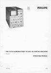
A complete installation is shown in Fig. I and the
samobasic arrangementwill apply in whole or in part,
whatever associatedequipment is used with the Quad
33. Installation is quite straightforward and should
present no difficulty to the intelligent enthusiastprovided the following notes are observed.
Pleasenote that threeprintedcircuit boardsfrom the
Quad 33 are packedseparatelyfor safetransit. These
must be insertedduring installation. See Fig. 3 and
also instructionscontainedin the packing.
Page Two
It
INSTALLATION
Normally equipment of this type may be either
mounted in a wide varietry of housings or used freestanding, and if you are designing your own layout it
might be advisable to assembleall the parts in a mockup form before deciding on the final arrangement,just
to make sure there are no unforeseen difficulties of
operation or inter-unit wiring, etc.
Adequate ventilation must be provided for units
producing heat, including transistorisedlx]wer amplifiers
and if the latter are to be mounted closer than about
12 inches from either control unit or tuner it might be
nec€ssaryto experiment with orientation and position
to ensurethat no hum is inducedin the latter units.
0lN plugto
DISCinputotO33
FIG. 1
Page Three
Close proximity of the control unit and tuners to
each other should causeno problem unlessthe control
unit is mounted immediately on top of the tuner, in
which casea spaceof about two inchesshould be left
betweenthem.
Hum can also occur if a low output magneticpickup
is too close to a mains transformeror if its leads run
closeto the mains wiring. (SeeFig. 2).
All metal parts must be earthedbut, becausemultiple
earth connectionscausehum, they should be earthed,
directly or indirectly, by one connectiononly, and the
whole installation earthed at one point such as the E
terminal on the rear of the control unit, OR the third
pin of the control unit mains socket,but not both.
(Note: All the Quad units are already bonded
togetherby their own inter-connectingcables).
Alwaysfollow the manufacturers'instructionssupplied
with pickup, motor, tape recorder,etc., and refer any
query which may arise to your dealer or in case of
difficulty to the manufacturerconcerned.
Page Four
PLUGIN BOAROS
2 x M12017
M120lS
I ' ( 2 O m m )t i c k
OUAD 33cover
Lugs .
CovsrLocatins Slid6
t)
FIG. 3
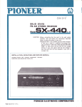
If the Quad 33 is not to be used free standing you
will require an aperture lA' x 3" as shown in Fig. 3
and a template is provided in the rear of this booklet
to assistin marking this out on the cabinet. The cover
is then removed from the Quad 33, the unit p'assed
through the aperture from the front so that its lugs
locate in the aperture,and the cover replacedfrom the
rear, thus gripping the cabinetpanel betweenthe Quad
33 front casting and its cover. The securing screws
shouldbe insertedfingertight and then givenone further
half-turn to lock the unit firmly in position.
The Quad 303 carries no controls and may be
mounted out of sight inside the cabinetor at any other
convenientposition in the installation.
The Quad 303 may be either stood on its feet on a
shelf or baseboard of a cabinet,or more securelyfixed
by drilling four holes in the shelf or board to coincide
with the feet centres,removing the feet securingscrews
and passingthe longerscrewsprovided,up throughthese
holes, through the feet which act as spac€rsto assist
circulation of air under the amplifier, and into the
tappedbushesin the base-plate.
Slots or holes should be cut in or near the baseand
in or near the top of any enclosedcompartment to
permit a flow of air upwardsthrough the compartment,
past and through the amplifier to assistventilation. In
confined spaceswhere the exit vents are not directly
over the amplifier a deflector plate of plywood or
asbestosmay be mountedat an inclined angleabovethe
amplifier to help guide the rising warm air towardsthe
exit vent and prevent an accumulation of warm air
under a closedhorizontal top.
Page Five
CO N N EC T I O NS
Din styls plugs showing method of assembly. See individual illustrations
for Din connections.
Control Unit to Power Amplifier
Two leads are supplied with the control unit. That
with a 4-pin connector at each end is reversible and
connectsthe control unit output to the power amplifier
input. The other connectsthe switchedmains supply
from the control unit to the power amplifier and the
2-pin plug at the control unit end of this lead is
reversible.(SeeFig. l0). Longer leads are permissible
whererequiredfor specialinstallations(seeSpecification
on page2l).
Pape Six
Power Amplifier to Loudspeakers
Ordinary lighting flex or similar cable may be used
for connectingthe loudspeakersto the power amplifier
unlessa very long run is involvedin which casea heavier
calibre cable should be used. As a rough guide the DC
resistanceof the cable should not exceed about 5,%of
the nominal impedanceof the loudspeaker.Each loudspeakershould be connectedto its appropriate llower
amplifier output so that the two pairs of wires are connected in the same way, to ensure that the speakers
operatein phase. For example,if the top output socket
on one channel is connectedto the left-hand terminal
of its speaker, the top output socket on the other
channel should also be connected to the left-hand
terminal of its speaker. This is quite straighfforward
but should there be any doubt the phasing can be
checked later experimentally. (See Page l5). Where
one loudspeakeronly is used for mono, phase is not
important and in this case either outlet may be used
and the socketsof the other channelleft vacant.
In caseswhereloudspeakers,such as the electrostatic
loudspeaker, also require an eneryising supply, the
\
instructions provided with the loudspeakershould be
followed. Each loudspeakershouldbe capableof handling the full output of the power amplifier.
Notez Quad electrostatic loudspeakersprior to serial
number 16800need slight modification before
being used with the Quad 303 amplifier.
The fourth position is to enable the amateur or
professionalengineerto provide any other circuit conflguration he may require and it alsoprovides,of course,
facility for accommodatingany new type of pickup
which may be introduced, requiring a different input
from existingtypes.
Pickup (Disc) Input
The pickup input is via a 5-pin plug and the same
connectionsare usedfor all types of pickup. The necessary changein input circuitry to suit different types of
pickup is achievedby the Disc Adaptor Board. This
board provides matching for pickups of low output
magnetictypes (Ml), high output magnetictypes (M2),
ceramictypes(Cl), and a spareposition (Sl), according
to the edge insertedinto the holder. (SeeSpecification
on Page20).
The M2 position should normally be used for most
magneticpickups but for those with very low outputs
Ml shouldbe usedinstead.
*6lril
ru.*tgdr foebd,
FIG. 5
Page Seven
input and an AM tuner for long distancereception to
Radio 2. Quad self-poweredtuners are supplied with
the correct connectorsand may be pluggedin immediately. The connectorsusedon other self-poweredtuners
should be adaptedas n€cessaryand thosealready fitted
u u' t
Rldb I
Tcpr Rrcold
fS.Qlt
,f,-,Sc
Sbrt
DISC ADAPTOR BOARD
Radio
T,?t--euAD33
(SeeFig. 7)
Socketsare provided on the Quad 33 for two radio
tuners to be connected. For example, an FM tuner,
usedfor mono or stereo,may be connectedto Radio I
Page Eight
FIG. 7
AgfSG
with the sametype of plug shouldbe checkedto ensure
that the sameconnectionsare used. The output of such
tuners should be suitable for the Quad 33 input of
l00mV and l0OK ohms (stereo) or l00mV and
50K ohms(mono).
The mains supply for these tuners should also be
taken from the mains outlet socketsat the rear of the
Quad33. (SeeFig. l0).
WARNING
On no accountshould the HT ILT lead of earlier Quad tuners
be connected to the power supplies sockets of the Quad 33
control unit. If such tuners are used a separute power pack
must be provided.
Tape
Three essentialfunctions are provided for tape
recording:
(l) to provide a signalof the right level for recording,
not afiected by any of the tone, filter or volume
controls and without afiectingnormal listening;
(2) to accept a signal of any likely level from the recorder for replay and subject this to all the
appropriatecontrol facilities,and
FIG. 8
TAPE ADAPTOR BOARD
(3) to monitor the signal off the tape during recording
without interrupting the recordingoperation,providing, of course, that the tape recorder has a
monitor output.
Page Nine
The plug-in Tape Adaptor Board provides three
alternativesignallevel settingseach for recordingand
replay on both channels,by means of small screws
insertedfrom the undersideof the board into the appropriate positionfor the signallevel of the tape recorder
on Pages20
to be used. (SeeFig. 9 and Specification
and 2l').
Scr€ws for adju$ing outpu!
lrcm Ou6d 33rotam r€coder
L6fthandchannol
In$dthi6dgs
inlo r€ar of
contol Untr
Righ! hand channcl
FIG. 9
Normally either one or both tapesocketsmay be used
for recordingand replay as convenientthe (L) and (R)
pins (SeeFig. 7) of the recordsocketbeinglinked inside
Pape Ten
the control unit to the correspondingpins of the replay
socket. Where the levels and impedancesare such that
cross-talk can appear in the cables and connectorsit
will be advisableto usecompletelyseparateconnections
for recordingand replay.
Mains Outlets
These socketsare intended for supplying the Quad
303 power amplifier and the FM stereotuner. Normally
it will be moreconvenientto run the mainssupplydirect
to tape recorder and gramophonemotor since these
incorporate their own on/off switching, but if other
units are run off the Quad 33 mains outlets the total
current drawn must not exceed2 amps.
Mains Input
A 3-pin connector is provided for the control unit
and this should be wired to the mains supply using a
suitable grade of flexible cable. In countrieswhere an
earth connectionis not usedor where an external earth
is connectedto the E terminal of the control unit the
third pin of the plug should be left blank.
Combined record/replay socket.
Any programme passing through
the Quad 33 may be recorded
w i t h o u t i n t e r r u p t i n gn o r m a ll i s t e n Ing.
Input for stereo/mono radio
Two switchedAC Mainsoutlets
f o r s u p p l y i n gr a d i o t u n e r a n d
poweramplifier
Additional inout for
tape replay only.
A C M a i n si n p u t .
I
Inputfor stereo,/mono
pickup.
QIAD 33
Output to power amplifier
Second radio. e.9., AM for long
distancereception,or Auxiliary input.
Ftc. 10
Plug-in printed circuit board
permitting independent adjustment of signal levels for both
recording and replay on each
channel.
Eanhterminal.
All signal connections comply with the intemationally
Plug-in printed circuit board
canying pickup input circuit.
This board may be inserted on
any of its four edges to provide
f o u r a l t e r n a t i v ei n p u t m a t c h i n g s .
used DIN standads.
Page Eleven
V o l u m ec o n t r o la n d
on/off switch
Q U A D n a m e p l a t el i g h t su p
when unit is switchedon
C o n t r o lf o r a d j u s t i n g
b a l a n c eb e t w e e nc h a n n e l s
I
I
I
I
l
I
I
I
I
I
P r e s st o s e l e c tl e f t - h a n dc h a n n e l
a n d u p p e rt r a c kt a p e .
P r e s st o s e l e c tr i g h t - h a n dc h a n
n e l a n d l o w e r t r a c kt a p e
Press both together for two
c h a n n e lm o n o
Page Twelve
l
Press to select the input required
Pressing the Tape button while
another input is selected also
provides AB monitoring facility
off tap€ during recording: Press
to listen to tape: Release to
listen to original.
FtG. t1
P r e s s i n gt h e C a n c e lb u t t o no v e r r i d e s t h e s e t t i n g so f b a s s ,t r e b l e
a n d f i l t e rc o n t r o l sa n d p r o v i d e sa
v e r y u s e l u lr e f e r e n c es t a n d a r d
F i l t e rS l o p ec o n t r o l ,u s e d i n c o n junction with the 5K, 7K and
1 0 K p u s h b u t t o n s ,r e m o v e s r e cord surface noise, high frequency distortions, eic (see
p e r f o r m a n c ec u r v e s )
INITIAL CHECKS AND OPERATION
Before connectingthe mains supply, ensurethat the
voltage marked on the rear of the control unit and the
settingof the selectorson the power amplifier and tuner
are correct for your mains. Theseselectorsare set by
withdrawing the cap $", rotating it to the required
voltageand pushingit fully home again. Then connect
the mains and rotate the volume cantrol to switch on
the equipment. The Quad 33 nameplate,the Quad 303
indicator light and the tuner scaleshouldnow light up.
reproduce a mono sigral from Disc or Radio I whether
tle programme sourceis mono or stereo. With Radio 2
or Tape inputs, however, apart from selecting loudspeakers,the Mon buttons also select left or righthand
inputs, each to its own speaker. In addition,* either
input may be reproducedover both speakersby pressing
the Stereo button as well as the <-Mon or Mon'+
button and, of course,Radio 2 or Tape.
* This facility wan not available prior to serial number 7500.
Volume Control
Pushbuttons (seealsoFilters)
The input (Radio 1, Radio 2, Tap, replay or Disc)
and the service(Stereo,or Mono on left-hand speaker,
right-hand speaker or both), are selectedby pressing
the appropriatepushbuttons.
With Stereo pressed, all inputs are connectedfor
stereoreproduction. In the caseof radio, the tuner will
automatically switch to Stereowhen a stereo signal is
received,reverting to Mono at all other times.
Pressing either or both of the Mon buttons will
The volume control is advanced to the appropriate
level, bearing in mind that apart from enabling a level
of sound to be obtained which suits the listening conditions of the moment,the volume control also has the
important function of adjustingthe intensityof soundso
that it is correctly related to the perspective of the
recordingor broadcast. This is obviouslyimportant for
realisticreproduction.
For example, if a voice is picked up close to a
microphonein a very absorbentstudio, then on reproPage Thirteen
duction that voice will take up a positionat the centre
of, and in the plane of the loudspeakers.For natural
sound,therefore,the loudspeakers
shouldradiatesimilar
powerto that of the originalvoice. If on the otherhand
the voice is picked up someway from the microphone
in a more live studio, then the voice on reproduction
will take up a positionsomedistancebehind the loudspeakersand it is clear that the power required for
natural sound is now very much less. The positionor
perspectiveof the reproducedsound is fixed at the
studio end and there is little that can be done at the
listeningend to alter it. It follows that the volume
settingfor natural sound is to a large extent fixed at
the studioend.
Filters (Seepage16).
The filtersaffectthe extremeharmonicrangeonly and
do not interferewith musicalbrilliance. Their purpose
is to enablethe maximum contentof the programme
to be reproducedwith the minimum distortion.
With most types of recording the distortion rises
Pape Fourteen
rapidly at high frequenciesand the wider the loudspeakerrangethe more audiblethis will be. It may be
removedor mitigatedby rotatingthe filter slopecontrol
anti-clockwise
from the levelposition. As the controlis
"
rotated, the quality and " cleanness
of the reproduction will improve. There will, however,be a point
beyondwhich further rotation degradesthe sound due
to lossof the usefulharmonicrange.
The pushbuttonsmarked5K, 7K and l0K, determine
the frequencyat which filtering commencesand that
marked 7K is the most useful for modern recordings.
Pressingthe 5K pushbuttontransposes
the filter operation to a lower frequencyfor use with older recordings
and pressingthe lOK pushbutton transposesit to a
higher frequencywhere it is useful with very good
recordsor high quality radio transmissions.
The Cancelbutton bypassesthe bass,treble and filter
controls to give a level response.This position is a
referenceby which the effectsof the settingsof the other
controlsmay be judged without upsettingthe position
of thesecontrols.
Balance Control
This merelyadjuststhe balanceof the two channels
and after initial adjustmentit shouldrequireno alterarecording
tion for normal listeningunlessa misbalanced
or broadcastis to be reproduced,which is unusual,or
unless the position of the loudspeakersor their
environmentis changed.
Bass and Treble Controls (Seepagel6).
LoudspeakerPhasing
If, for any reason,there is any doubt about the way
in which the loudspeakersare connected(seepage 6)
their phasingmay now be checkedby playing a mono
disc over both channels,when the soundshouldappear
to emanatefrom a point midway between them. If
this is indefinitethe connectionsto either of the loudspeakers,but not both, should be reversed.Correctly
connectedthe speakerswill give a definitecentresound
by a more full bodiedsoundin the
sourceaccompanied
tenorand bassregisters.
The musical balanceof a programmeis carefully
adjustedduring recordingor broadcastingand adjustmentof the bassand treblecontrolsshouldnot normally
be necessaryunlessan inferior loudspeakeror the listening environmentproduces some effect which needs
correction.Onceset for a particularinstallation,therefore.thesecontrolsshouldbe little used.Smalldeviations
of the bass control will affect very low notes only.
Greaterdeviationsaftect not only the very low notes
to a greaterextent but also the high bass notes. The
treblecontrol afiectsbrilliance.
Page Fifteen
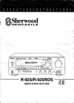
As the Filterslope control
is rotated lrom 0 to 25 the
filter swings from a level
response to a steep cut as shown.
f is the frequency selected
bythe skHz. TkHz or'10kHz
push buttons.
/
a
I
&
t
o
&
s
@
nt
)
7
/
All sub-audio signals below
20Hz are drasticallyf iltered
as shown.
Thethree curuescorrespond
to minimum,leveland
maximum settings olthe Bass
t
ttl
,l
control.
s $
Page Sixteen
o
1 6
1
2
"
p
lA.
The Bass STreble controls provide smooth and independent
adjustment of the responseto suit programme or environment
QUAD33
PERFORMANCE
CURVES
LoudspeakerPosition
The standardof reproductionobtainedfrom any loudspeakeris influencedby both its position in the room
and its position in relation to the listening area. The
optimum position can only be found by experimentand
this cannot be carried out quickly or in a perfunctory
manner, if long term non-fatiguing listening is to be
obtained.
It is a fact that the standardof reproductionin many
homes,both mono and stereo,is significantlybelow that
which could have beenobtained had sufficientattention
been paid to loudspeaker positioning. Broadly, for
stereothe two loudspeakersshould be 6ft' to 8ft. apart
with the listenerat a similar distancefrom each.Clearly,
when more than one person is listening they cannot
both occupy the same position and all listening tests
should aim at obtaining good stereoover a reasonable
area.
This can usually be achievedover an area immedi
ately behind the listening point already defined'with a
width equal to the distancebetweenloudspeakersand
with a similar depth.Outsidethis areathe overall quality
should be satisfactoryalthough the perspectivemay be
of 6ft. to 8ft. is basedon
degraded.The measurement
a small room. With a larger room the scale may be
increasedaccordingly.
The quality of the resultsobtained will dependupon
the following:(a) The position of the loudspeakerswith respectto
the room boundaries (and sometimes floor
joists).
(b) The direction of loudspeakeraxis.
(c) The position of large piecesof furniture.
With stereothe following may be added:(d) The distanceapart.
(e) The point of intersection of the loudspeaker
axes.
(f) The relation of the base line (an imaginary
straight line joining the two speakers)to the
room boundaries.
(g) The positionof the listeners.
The instructionssupplied with the loudspeakermay
resolvesomeof the variablesand the rest must be solved
Page Seventeen
by experiment. Few people can successfullycomplete
theseexperimentsat a singlesessionand it is strongly
recommended
that the followingprocedurebe adopted.
The loudspeaker(s)
should be tried in the various
room positionswhich appearphysicallypossible,in
order to ascertainwhich positionsare likely to be
worth further investigation.
The loudspeakershould now be used in each of
thesepositionsfor normal day to day listening.The
usual attention should be paid to the programme
itself without any consciousconcentrationon the
quality. In this way the optimum positionfor most
satisfactorylistening will soon becomeapparent.
O P ER A T I O NSU MMA R Y
With all the testsdetailed in the previoussection
completed,operationof the Quad 33 should now be
readily apparent and completelystraightforward. It
may be summarised
asfollows:Use the pushbuttons to select input and system
required.
Adjust the volumecontrolfor a levelof soundsuitable for the programme.
Page Eighteen
Adjust the filter to obtain the bestquality inherent
in the programmeremembering
that this meansfiltering aslittle as possible.
Adjust bassand treble controlsonly if it is necessary to alter the musicalbalanceof the programme.
Adjust the balancecontrol only if the programme
levels of the two channels are themselvesout of
balance.
SERVICE
Normally the dealersupplyingthe equipmentwill be
able to assistwith adviceor any attentionthe equipment
may require but in caseof difficulty you should return
any Quad unit you wish to have checked,direct to our
ServiceDepartment,or that of our. main agent in the
country concerned,carriagepaid and preferablypacked
in its original carton. If this is not availablea pack
will be forwardedon request.
Do not forget to enclosea note giving your nameand
address,full details of the reasonfor returning the unit
and all the symptomsyou have observed.
SPECIFICATIONFOR QUAD 33 CONTROLUNIT
DISTORIION:
All controls level, O'SVrms output,
with anv inout.
Any coritrofsettings and any level
within overload ratings
RESIDUAL NOISE:
0-30 phon weighting ls'7kHz bandwidth
controls level or cancel
FREQUENCY RESPTONSE:
Any input, any output
RIAA or flat as appropriate
TONE CONIROIS:
:L ldB of published curves
(see page 16)
FILTERSI:
To pubtished curves at Sktlz,TkHzandl0kJlz!
(see page 16)
INTER.CHANT\IEL
BALANCE:
Within ldB with volume control varied
from maximum to -45db
BALANCE CONTROL
RANGE:
9dB either way
CROSSTALK:
o.o2%)
Hz
) 30-lo,ooo
o.r'% )
:
-90d8
t0.5dB 30-20.000Hz
3/o
Dependant on input source impedances.
Reilav/record typically better 1an 70dB 30-10,000Hz
Intirchinnel tvrjiiattv better than 40dB 30-10,000 llz
Page Nineteen
FOR QUAD33 CONTROLUNIT
SPECIFICATION
INPUTS(all voltagesrms)
DISC
l.
,
Input l*vel
for 0.5V
lMain Output
3.
Maximum
Input
4.
Signal to noise
referred to level
in Col. 3
0-30 phon weighting
l00K ohms
lOOmV
2Y
85dB
H
any
4OK ohms
1V
10v
85dB
M
any
40K ohms
400mV
4V
85dB
L
any
40K ohms
lOOmV
1V
85dB
2mV at
lkHz
40mV at
lkHz
70dB
5.6mV at
lkqz
120mVat
lkHz
8odB
l00mV at
lkHz
l.2Y at
lkHz
MI
Low Output Magnetic
0.5-2mViCmlSec.
68K ohms
M2
High Output Magnetic
1.5-6mV/CmiSec.
68K ohms
Ceramic
450-800pF
2l80mvicm/Sec.
Special
cl
s
Page Twenty
Loail
Impedance
20K ohms or less
RADIO
TAPE
REPLAY
Recommended
Source Impedanoe
FOR SPECIAL REQUIREMENTS
I
;t
SPECIFICATIONFOR QUAD 33 CONTROL UNIT
OUTPUTS(all voltagesrms)
Level
TO POWER AMPLIFIER
TO
TAPE
RECORDER
0.5v
Maximum Cable Lengtbs (Using 20pF/ft Screened
Lead)
Source
Impedance
Recommended
Load Impedance
lK ohms
lOK ohms or over
100 feet
H
l00mV *
5K ohms
25K ohms or over
150 feet
M
20mV *
800 ohms
any
any
L
3.7mV*
any
any
180ohms
* 3OVoprogramme modulation
WEIGHT:
6i lb. (3Kg.)
DIMENSIONS:
width
Height
Depth
POWER INPUT:
l0+" (260mm)
l1t" (92mm) free stalrding, 3|" (83mm) panel
6 j" (l65rnm) free standing
5*" (l40mm) behind cabinet panel when mounted
(Allow a further 2i" 64mn) beyond rear
panel for connectors)
100-130/200-260V50-60 Hz 1.5 Watts.
Page Twenty-one
SPECIFICATIONFOR QUAD 303 POWERAMPLIFIER
The figures and curves refer to measurernentson either channel,
with or without the other channel operating.
POWER OUTPUT AND DISTORTION
(with unrestrictedbandwidth)
FREQUENCY RESPONSE:
OUTPUT SOURCE IMPEDANCE:
INPUT LEVEL:
INPUT IMPEDANCE:
HUM AND NOISE:
INTDRCHANITIEL CROSSTALK :
STABILITY:
POWER INPUT:
WEIGHT:
DIMENSIONS:
OIIIER
APPLICATIONS:
Page Twenty-two
O.O3% ll ^7O Hz
cj.6ln I anv level up to 28w 16 ohms load
.titit uZ
nnY level up to 45w 8 ohms load
o.lV;
io nri
1
-ldB (ref: lkHz) at 30 Hz and 35kHz into 8 ohms
-ldB (ref : lkHz) at 2O Hz and 35kHz into 16 ohms
0.3 ohms in series with 2000pF and 6pH.
0.5V rms fqr 30 watts into 16 ohms
22K ohms in parallel with 60pF
-l00dB below full output
30-10,000 Hz better than 60dB. Input load I K ohms.
unconditionally stable with any load.
100-125 or 200-250V 50-60 Hz.
40-200 watts depending on signal level.
l8 lb. (8.2Ke.)
Width 4i" (l20mm.)
Heisht 6+" (159mm.)
Depth l2*" (324mm.)
(plus 1]" (38mm.)for connectors).
The ampli{er may be used for any purposes into load
impedancesgreater than 8 ohms. Below 8 ohms applications
should be rbstricted to music and speechreproduction
or intermittent sine-wave dutv.
I
I
I
;
t
t
t t
r r |
8n Resistiw Lod
70Hz & 70OHz
-------
o
i
I
I
-
VA ohose
-----
VA ohqse 45"
..
...
.
I
lOKHz
16^ Resistiw Lood
TOHz & TOOHz
........
I
loKHz
Oo(Resistive)
VA ohose 96o(Reocriw)
Woits
+l
QUAD 303
PERFORMANCE
CURVES
8ntu
o
-t
o _ ,
-3
m
t@
--------
t@
hnr
tuqsq
tud
Le$ tfEn tZ Dbt at aryfiq|ry
L6dbolzqdataryftqumry
Odb =4li watts
0.m
&@
Page Twenty-three
6uarantee
This instrument is guaranteedagainst any defect in material or workmanship
for a period of twelve ialendar months frorn the date of purchase.
Within this period we undertake to supply replacementsfree of charge for
provide.d.that such
any parts whici may prove on examinatioi to be defectiu_e
tieieitiveness is not ihi result ol misuse (including use with unsuitable ancillary.
eq'uipment),accident or negligence,and further that the instrument was purchased
ai tie proper retail price prevailing in the country ol purchase.
Any set requiring service under this guarantqeshould be taken to the suppli.er
throuih whom it w7s purchased,or, in-case of dificulty, it should be carelully
puckeZ and consigned,'carriage paid to the main distributor for the country-of
'purchase
quoting ihe date and place of purchase. It must not be sent to any other
agent or distributor except by special arrangement.
This guaranteeis valid only when these-conditionsare complie_dwith and does
not cove"rlabour or carriage iosts involved in any repair under the guarantee.
No guarantee card is packed with the equipment.
Page Twenty-four