1
STEREO CASSTTTE TAPE DECK
MAGNETOPHONE
A CASSETTE STEREO
STEREO-CASSETTENDECK
DR.M33HX /DR-M44HX
OPERATING INSTRUGTIONS
MODE D'EMPLOI
BEDIENUNGSANLEITUNG
FOR ENGLISH READERS
POUR LES LECTEURS FRANCAIS
rÜR oeurscHE LESER
PAGE 1-PAGE
19
PAGE 20- PAGE 37
SEITE 38 - SEITE 56
IMPORTANT TO SAFETY
WARNING:
TO PREVENT FIRE OR SHOCK HAZARD, DO NOT EXPOSE THIS APPLIANCE
TO RAIN OR MOISTURE.
GAUTION:
1.
Handle the power supply cord carefully
Do not damage or deform the power supply cord. lf it is damaged or deformed, it
may cause electric shock or malfunction when used. When removing from wall outlet,
be sure to remove by holding the plug attachment and not by pulling the cord.
2. Do not open back plate
ln order to prevent älectric shock, do not open the back plate. lf problems occur.
contact your DENON dealer.
3. Do not place anything inside
Do not place metal objects or spill liquid inside the cassette deck. Electric shock or
malfunction may result.
Model DR.
Serial
Please, record and retain
the rating
label.
No.
the Model name and serial number of your set shown
on
IMPORTANT
(BRITISH MODEL ONLY)
The wires in this mains lead are coloured in accordance with the following code:
Blue:
Brown;
Neutral
Live
The colours of the wires in the mains lead of this apparatus may not correspond
with the coloured markings'identifying the terminals in your plug proceed as follbws.
The wire which is coloured blue must be connected to the terminal whicn is marked
with the letter N or coloured black.
The wire which is coloured brown must be connected to the terminal which is marked
with the letter L or coloured red.
FOR YOUR SAFETY
(AUSTRALTAN MODEL ONLY)
To ensure safe operation, the three-pin plug supplied must be connected only with
a standard three-pin power point which is effectively earthed through the normal
household wiring.
Extension cords used with the equipment must be three-core and be correctly
wired to provide connection to earth. Wrongly wired extension cords are a major
cause of fatalities.
The fact that the equipment oper€tes satisfactorily does not imply that the
power point is earthed and that the installation is completely safe. For your safety,
if in any doubt about the effective earthing of the power point, contact a qualified
electrician.
-2-
Thank you very much for purchasing the DENON component DR-M33HX/M44HX.
The DENON DR-M33HX/M44HX is a top-line stereo cassette tape deck, capable of
outstanding performance in combination with high grade hi.fi systems.
DENON proudly presents this advanced tape deck to audiophiles and music lovers
as a further proof of DENON's non-compromising pusuit of the ultimate in sound quality.
The high quality performance and easy operation are certain to provide you with many
hours of outstanding listening pleasure.
TABLE OF
FEATURES.
SAFETY INSTRUCTIONS FOR AUDIO SET.
SPECIFICAT|ONS
.
CONTENTS_
.
FRONT PANEL SWITCHES AND
CONTROLS..
AUTO TAPE SELECT FEATURE
....
CoNNECT|ON.....
CASSETTE TAPE .
PLAYBACK
RECORDTNG
AUTO TUNNING SYSTEM (DR-M44HX
CENTRALIZED DISPLAY
only)
........ 3
.., .....,. 4
........ 5
......6-7
........ 8
....... 9
.... 9
........1O
.......11
.
....I2-I3
.........I4
only)..
........15
.......15
..,......16
LEVEL
PROPER RECORDING
RECORDING BIAS ADJUSTMENT (DR-M33HX
SWTTCH
TIMER RECORDING/PLAYBACK
PAUSE/MUTE KEY.
DOLBY HX PRO HEADROOM EXTENSION SYSTEM.
DOLBY C NOISE REDUCTION SYSTEM
MA|NTENANCE ...
SYMPTOMS OFTEN MISTAKEN AS BREAKDOWNS
MONTTOR
....L4
.... ...17
.........L7
........17
...... ..18
....19
r
Computer-controlled servo technology
. Direct drive closed-loop dual-capstan. tape transport (DR-M44HX)
. Closed-loop dual-capstan tape transport (DR-M33HX)
. Silent, soft-touch controls provide maximum ease-of-use.
. Computer-controlled, full-logic tape controls enabie fool-proof operation"
r Three-head design utilizes the DENON's new SF record/playback combination head assembly.
r Dolby HX PRO headroom extension.
r Computerized Linear counter with memory stop.
r Auto tuning system provides automatic level and EQ adjustment. (DR-M44HX)
rDolby-B/C noise reduction systems (Double Dolby System).
r Extended range, dual-color fluorescent peak meters with auto peak hold.
r Auto tape selector.
I
r
Remote control connection
terminal.
,
High-grade 5-pole DC reel drive motor.
rBias fine adjustment (DR-M33HX).
ODolby noise reduction and HX PRO headroom extension manufactured under license from
Dolby Laboratories Licensing Corporation. HX PRO originated by Bang and Olufsen. "Dolby", the
double-D symbol and "HX PRO" are trademarks of Dolby Labsratories Licensing Corporation.
-3-
SAFETY INSTRUCTIONS FOR AUDIO SET
I !NSTALLATION
1. Operate the set only from a power source which is indicated on the rating label (indication)
at the back of the set.
2. Frayed cords and broken plugs may cause a fire or shock hazard. Do not damage the power cord.
r Do not cut and splice the power cord.
oWhen removing the power cord from wall outlet, be sure
to unplug by holding the plug attachment and not by pulling the cord. Do not hold the plug by wet hand.
r Call your service technician for replacement of damaged cords and plugs.
Check voltage
Select a place so that the
location or position does not
3.
interfere with the proper
ventilation of the set for
releasing heat generated
during operation.
r Select a f lat and level surface
Do not pinch power cord.
rffi
Do not splice power cord.
on a bed, sofa, rug, etc.
"builtNever plaie the set in a "bu
proper
in" enclosure unless prol
ventilation is provided.
. Never place the set near or
over a radiator, heat regis ter
or stove.
r Avoid locatiöns where the
is exposed directly to the :
o
allowing enough space for
setting up and operation.
Avoid heat.
. Never block the bottom venlight.
tilation holes placing the set
I usE
1. Do not expose the set to rain or water (liquid). Do not spill liquid or insert metal objects
inside the set. Rain, water or liquid such as cosmetics as well as metal may cause electric
shorts which can result in fire or shock hazard. lf anything gets inside, unplug the power
cord and have a DENON service technician check your set before further use.
2. Never leave your se\ switched on when leaving the house. For added protection of your audio
system during lightning storm or when the set is to be left unused for a long period of
time, be sure to unplug the..power cord from the wall outlet.
3. Take care so that the set is not dropped to avoid damaging the cabinet which defeats safeguards or injuring yourself. lf the set has been dropped or the cabinet has been damaged,
unplug the set and have it checked by a DENON service technician to restore the safeguards.
r
Remove power in your absence.
I SERVICING
1. The servicing
2.
Do not drop.
No user-serviceable parts inside.
of set must not be attempted by yourself beyond that described inthe operating
instructions. ln case of problems that cannot be settled by referring to your operating instructions, unplug the power cord and contact your DENON dealer. No user-servicable parts
are inside the set. Only qualified service technician can service inside your set.
Refer to the operating instructions for maintenance and cleaning.
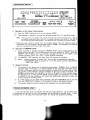
SPECIFICATIONS
.
Vertical tape loading 4-track 2-channel stereo cassette tape deck
SF Record/Playback Combination head x L
Erase head (Ferrite) x 1
o Motors
FG Servo Direct Drive motor (for capstan) x 1 (DR-M44HX)
Electronic servo DC motor (for capstan) x1 (DR-M33HX)
S-pole DC motor (for reel winding) x 1
r Tape Speed
4.8 cmisec.
o Fast forward, rewind time. Approx. 8O sec. with a C-60 cassette
o Recording bias . .
Approx. 1O5 KHz
o Overall S/N ratio.
Dolby C NR on .. . 75 dB (CCIR/ARM)
(at 3% THD level)
o Overall frequency response. 25-ZO,OOOHz +3dB (at
-2OdB METAL tape)
r Channel separation.
(at
KHz)
40
l
more than
dB
r Crosstalk.
more than 65 dB (at 1 KHz)
. Wow & flutter
O.O35% w.rms (DR-M44HX)
O.O4% w.rms (DR-M33HX)
Type
o Heads
o lnputs
line
..
o Outputs
line...
headphone
rAccessories.....
. Power supply
. Power consumption
77.5mY (-2OdB) input level at maximum
lnput impedance: 50 Kohm unbalanced
775 mY (O dB) output level at maximum (with 47 Kohm load,
recorded level of 2OO pwb/mm)
1.2 mW output level at maximum (optimum load impedance 8 ohm
-1.2
Kohm)
Parallel pin cord
x
2
o
Dimensions
50 Hzl6O Hz compatible, voltage is shown on rating
25 W (DR-M44HX), 24 W (DR-M33HX)
434 (W) x 115 (H) x 286 (D) mm
o
Weight.
5.6 kg
label
r Above specifications and design styling are subject to change for improvement.
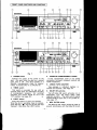
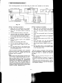
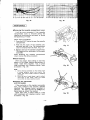
FRONT PANEL SWITCHES AND CONTROLS
0l'_tEE
!====III==:
ffioffirEcB
!1n
t,
Lr
Fig.
1,
fi!1
I;;;?;ir;?.
Lt
t_r
1
POWER switch
Controls the supply of AC power to the
deck. One push turns the deck on, a second
push turns it off. The deck remains in a
stand-by (non-operative) mode for approximately 4 seccjnds afier it is switched on.
2.
TIMER switch
This switch is provided for use with
an
optional audio timer for unattended recording
or
morning-alarm playback. For non-timer
this switch should be set in the
"off" position (sed page 16):
.e
operation,
3'
EJECT button
Press this button
4. CASSETTE COMPARTMENT GOVER
lf this compartment cover is not closed
completely, the deck's transport controls will
remain inoperative.
5.
LINEAR TAPE COUNTER
Tape' passage is indicated digitally in
minutes and seconds. (See Page 14)
6.
DOLBY NR switches
The left Dolby NR switch activates (in) or
deactivates (out)
reduction
the deck's Dolby
circuitry. The right switch
noise
selects
between Dolby B-Type (out) or C-Type NR (in).
(see page 17).
to eject the cassette.
the deck is operating (tape is running),
press the stop ( I ) key first to stop the tape
transport; then press the EJECT button.
When
t+tq
-6-
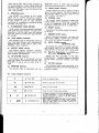
7.
MPX FILTER switch
The MPX FILTER switch should be used to
prevent interference with the Dolby NR circuit
when making Dolby NR encoded recordings of
FM stereo programs. When making Dolby NR
encoded recordings from any program source
other than FM stereo, leave this switch in the
"off"
8.
1eu1) position.
MONITOR switch
The SOURCE (in) position of this switch
allows you to monitor the source program
before it is recorded. The TAPE (out) position
of this switch is used for tape playback
monitoring or simultaneous monitoring during
recording (see page 15).
9.
FLUORESCENT PEAK METERS
These meters indicate recording or piayback
peak levels for each channel. For peak levels
exceeding -l dB, the Auto Peak Hold featuae
holds the peak level reading for approximately
1.5 seconds.
lO.
TAPE SELECT indicator
This indicator light is interlocked with the
Auto ,Tape Select feature which automatically
adjusts the deck to the type of tape in use.
(NORMAL, CrOz,
or
METAL).
11.
OUTPT T LEVEL controt
This control adjusts playback, recording
monitor, and headphones output levels for the
both channels simultaneously.
t2,
NR SYSTEM indicator
This indicator light is interlocked with the
Dolby NR switch and informs the user that
Dolby NR is in use as well as which (B or C)
Type.
13.
MONITOR indicator
This indicator light is interlocked with the
MONITOR switch to inform the use of the
selected monitoring source-TAPE or SOURCE.
14.
INPUT LEVEL tontrots
These controls are used to adjust recording
levels for each channel. The front control is
for the left channel; the rear control for the
right channel (see page 14).
15.
PHONES jack
For private music enjoyment without disturbing others, or for monitoring a recording,
a set of headphones may be plugged in.
lmpedance should be from 8 to'120O ohms.
16. RESET button
Operation of the button resets the counter
to all zero.
L7.
MEMORY STOP button
i
.i
During rewinding operations, the tape will
stop at the " OOOO " counter point automatically when this button is pressed in.
18. AUTO TUNING system
(DR.M4AHX only)
By pushing this button, the deck automaticaily adjusts itself for the optimal recording
characteristics of the tape that is being used.
19. Bias Fine Adjustment (for NORMAL and
CrO, tape) (DR-M33HX only)
Adjust the bias according to the tape
characteristics. Standard biasing is obtained
at the center click-stop position. (see page
15).
2L.
HX PRO indicator
This indicator lights when the power is on
to indicate provision of the HX-PRO headroom
extension system.
20. Tape transport controls
I
Press
to playback tape.
to stop tape in any mode.
I
STOP KEY
Press
<<
REW KEY
Press for fast rewind.
>>
FF KEY
Press for fast forward tape winding.
o
REC
O
RECORD KEY
rr
it?f
II
PAUSE/MUTE KEY
I o began recorcling, press the RECORD and PLAY
keys simultaneously. lf only the RECORD key is
pressed, the deck is placed in the REC PAUSE
(record standby) mode.
;Phe PAUSE key causes the tape to stop momen.
tarily during recording or to mute the recording
input to create blank (non.recorded) portions on
the tape (see oaee l7)
q
T
,A
f,
:ä
.H
ä
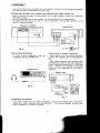
CONNECTION
. Leave your entire system (including this cassette deck) turned ofi untit all connections between
the deck and other components have been made.
I
Connecting the deck to an amplif ier and attaching the remote control unit
. Before connecting the deck to your amplifier, it is a good practice to review your amplifier's
instruction manual.
. Use the white plugs for the left channel, and the red plugs for the right channel.
. An optional remote control unit (RC-57) can be attached to the rear DIN connector of the
deck for remote operation.
Receiver or amplifier
Remote control unit
50
rGonnecting Headphones
To listen through headphones, plug your
headphones into the PHONES jack.
Gassette Deck
/&Hz
r Connection to Another Tape Deck
When dubbing to or from another tape deck,
connect this cassette deck as illustrated below:
Many stereo amplifiers and receivers have
tape dubbing circuitry so that tape duplication
can be performed between two or more tape
decks. Review your amplif ier's instruction
manual for a full explanation of this mode of
operation.
Dubbing from
Fis. 3
a
seCOnd
deck
LtilEour
Fig. 4
r lnstallation Precautions
lf the deck is placed on or too near an amplifier or tuner, noise (induced hum) or beat interference may result (especially during AM reception). lf this occurs, separate the deck from
other components or reorient its position.
-8-
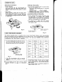
CASSETTE TAPE
r Handling Frecautions
o C12O cassettes
C12O cassettes are
r Storage Precautious
not recommended
o
as
they use a very thin tape base which may
become tangled around the capstan or pinch
roller.
Do not store cassette tapes in a place where
they will be subject to:
. Extremely high temperature or excessive
moisture
. Excessive dust
. Direct sunlight
. Magnetic fields (near TV set or speäkers)
o To eliminate tape slack, store your'cassettes
in cassette cases with hub stops.
r Tape slack
Before putting a tape into the deck, take
qp any slack with a pencil or your f inger tip.
This precaution is also to prevent the tape
r Accidental Erasure Prevention
. Every cassette has erasure prevention tabs
for each side. To protect your valuable
from becoming entangled around the capstän
or pinchroller.
recorded tapes from accidental or inadvertent
erasure,. remove the tab for the appropriate
'
side with a screwdriver or other toois.
. To record on
a
tape with the
erasure
prevention tabs removed, cover the tab holes
with plastic tape.
Erasure prevention
Fis. 5
Erasure prevention
tab for side
tab for side
A
B
Fig. 6
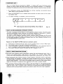
AUTO TAPE SELECT FEATURE
This Stereo Cassette Deck is equiped with an Auto Tape Select feature which automatically
selects the optimum bias and equalization for the tape in use. This is accomplished by sensing
the tape type detection holes in the cassette housing. The Tape type (NORMAL, CrOz, or METAL)
is indicated by the TAPE SELECT indicator.
.
lf a tape without tape type detection holes is
used, the TAPE SELECT indicator will not indicate the correct tape type and the deck will
automatically adjust itself for normal tapes.
Brand
NORMAL
DENON
XDX 3H
DX3
UL
MAXELL
UDI
XLI
XLTS
TDK
tection ho
Detection holes
Fig. 7
.
lf
DX7
XHD
7E
SA
MA
FUJI
DR
ER
FR- II
SCOTCH
BX
CX
XS_
AHF
HF
XDXM
MX
SA-X
SONY
METAL
XLI
XLIS
OD
for metal
for chrome tape
AD
CrOz
MA_R
FR METAL
[
UCX
UCX_S
METALLIC
the döck is switched on with no cassette
loaded,
the TAPE SELECT indicator will show
..METAL''.
r For the details of
TUNING SYSTEM''
only)
. Typical
FeCr tape, see the "AUTO
tape brands for each type are listed
.,, in the above table. There may be differ-
on page 12. (DR-M44HX
9-
ences in sensitivity of a few decibels between
tape brands.
r This Cassette Deck is optimally aligned for
tapes marked with " X ".
. Switch on your amplifier or receiver.
. Set the TAPE MONITOR switch on your amplifier or receiver to the TAPE position.
. Operate the deck in numerical order as illustrated below:
@t [p"*a
pr.rsh the switch
@)
to turn "on" ( r ) the
power
r-oaa the cassette tape
Push the PLAY KEY
( [tPLATl indicator will licht up)
Playback sound is fed into
the headphone set
@
tci=ztt
lburPur
Press the EJECT button to open
the cassette compartment.
LEVEL'l
Adjust the OUTPUT LEVEL
@ n*cEt
Check to make sure that it
ll.aöNrroRl
Press this switch to the TAPE
( I ) position.+(See page 15)
is turned "off".
For recordings made without Dolby NR, set to "of f ".
For recordings made with Dolby B NR, set to "on"
and "B".
Fis. 8
For recordings made with Dolby C NR, set to "on"
and "C".
I ) key. To pause during playback, press the
To restart the tape, press the PLAY ( > ) key.
When playback is finished, press the stop (
PAUSE/MUTE ( ll
lf
) key.
different types of Dolby Noise Redugion are used
response will be adversely effected.
l0I
for record and playback,
playback
. Switch on the source component (tuner, amplifier, etc.)
. Set the TAPE MONITOR switch on your amplifier or receiver to the SOURCE position.
@ mwäA Push the switch to turn "on" ( r ) the power.
(TheDprÄYlana
filFEöl
t-@I-:E
E-ttti;;;;;;
ts@DEfuI:Et_]
ffi
liNPUr LEvet-".l
Adjust the recording
Press the EJECT button
to open the
compartment.
Ievel. +(See paee L4)
cassette
@ Fa'ir*l
Press this switch
SOURCE
Check
to
indicators wiu tight up.)
to the
(^) position-(see
page 15)
make sure
is turned "off".
For FM recording using DOLBY NR, set
.^\.-..-----NRI
(5)
IDoLBY
to "on" ( ^
Set, in accordance with the recording to be made.
For recordings without Dolby NR, set to "off ',. For
recordings with Dolby B NR, set to "on,' and ,,8".
,.on',
For recordings with Dolby C NR, set to
and
"C". Future mistakes during playback can be avoided
if the cassette is so markbd fbr DolbyNR encoded
recordi ngs.
Fig. 9
@
*r"o*o
WheLpls:93d, the deck goes into the record standby mode.
rne IIJFEöI ano F-flR]..l:1ÜEE7MuEl lamps wil tight, and both
;:i;'t;?'{3i?0",?1,,?10,3{,i;?:?::.yJJ,'i,"'il,?"1!'?n::i}";:
made in the record standby mode.
I
When recording is finished, press the STOP ( I
)
key.
lnstant playback to recording mode
To start recording right after previously recorded material on a tape, this feature is quite
convenient.
1. Play the section of the tape with previously recorded program material.
2. When the previously recorded material finishes, press both the RECORD ( O ) key and the
PLAY ( ) ) key at the same time. Without stopping, the deck will go from the playback to
the recording mode, and the leR-föl indicator tamp-wiil go on.
Gaution:
Be careful not to erase important'recordings by mistake. Mis-erasing can be avoided. if
you remember the two steps below:
1. lf the PLAY ()) key is pressed while the laF-flöl indicator is on, the tape wiil be recorded.
2. lf the PLAY ()) and RECORD (O REC) key are pressed at the same time, the tape will be
recorded.
-
1l
-
)
AUTO TUNING SYSTEM
(DR-M44HX only)
The same type of tapes can have slightly different perfo'rmance characteristics depending on the tape brand or individual tape characteristics. This occurs even though the deck
automatically selects bias according to type of the tape placed in the deck. The auto tuning
system automatically further fine tunes the deck to achieve the optimum recording response
according to individual tape characteristics, and stores this information in its memory.
Auto Tuning System Gontrols and lndicators
rAUTO TUNING ...During tuning operations, this
tnotcaror rtasnes.
.
.. .. ..Lights when optimum tuning is
completed and the information
stored in the memory.
[RlJlREt{CEl....Displaysthestandardref erence
position before auto tuning.
MEMORY/REF Key:
Operation of this key alternately selects the
stored response (after auto tuning) and the
factory preset standard response.
START
Fig.
Key: This begins the tuning
sequence.
1O
Auto Tuning System Operation
1. Place the cassette. (The TAPE SELECT indicator will indicate the tape type).
2. When the MEMORY STOP indicator is lit, press the memory stop button to deactivate
function during Auto Tuning.
3. Press the START key.
ffi
lf not deactivated, it will interfere with the tuning
(
ffiF-l
START
ffi
START
1)
MEMORY/ REF
\)
Tuning begins and the AUTO TUNING in'
dicator lamp starts flashing.
(The deck enters the record mode.)
(2)
Fis.
When tuning is completed after approxi'
mately 6 seconds, the tape is automatically
rewound to a point just preceding the original
start point. The tuned response is stored in
the memory. (The MEMORY lamp comes on
11
and the deck returns to the STOP mode.)
The deck is now ready for recording.
[{EMORY/REF
(3)
\)
Tuned response (MEMORY) and standard
response (REFERENCE) can be alternately
selected by pressing the MEMORY/REF key.
Fig. 12
- t2i.L
this
operation.
. The auto tuning system can store one optimized recording response setting each for
CrOz and METAL positions. (e.g.)
ruPosrtlor
AUTO START MEMORY
TUNING
Optimum recordlng response
-+
REFERENCE
Preset standard response
NORMAL
CrO,
METAT
Blank
du*o"
diernorY
O
roxsHr
NORMAL,
O
o,no,,,
roxur
For tape positions with optimum recording responses stored in the memory, the MEMORY and
STANDARD responses can be alternately selected by pressing the MEMORY/REF key. (The MEMORY
and REFERENCE indicator lamps correspond to the selected key position.)
For a tape position (CrO2 in this example) with no optimum response stored, a new tape response
can be quickly determined and stored in the memory.
When a tape response for each of the three positions
stored in the memory, six different
recording responses can be selected.
. lf tuning is attempted more than once for the
same type of tape, the optimized response
for the last tape will remain in the memory and all the previous responses will be cleared.
r lf the tape is started from the clear leader tape, the time that it takes for the leader
tape to clear the heads will be added to the tuning time. ln these cases, the tape will
be rewound to a position just prior to the beginning of the magnetic tape. The counter
may not indicate the original start position.
r Before the tuning sequence is performed, MEMORY response cannot be selected even
if the MEMORY/REF key is pressed.
rAll memory contents are cleared when the deck is switched off.
. lf the START key is pressed during recording, the MEMORY response will automatically
be switched into the STANDARD response.
o lf the START key is pressed during playback of a recorded tape with the erasure prevention
tab intact, the tuning sequence will begin and part of the recorded tape will be erased.
Be sure to remove the erasure prevention tabs from recorded tapes.
r lf the tape is too loose or too tight, the AUTO TUNING will not function properly. Take
care to make sure that tape tension is even.
o lf the MEMORY STOP function is activated during AUTO TUNING, it may interfere with
the tape running of the tuning operation. Make sure MEMORY STOP is off before tun.
ing is begun
I FeGr Tape
Since the Auto Tape Select feature does not have a separate position for FeCr, the optimum
recording response for FeCr tapes will be achieved only if the Auto Tuning feature is used.
(When playing. a FeCr tape recorded on the DR-M44HX Deck on another deck, set the deck's
tape selector to the NORMAL position).
-13-
1.
.
*
ud*ft*g*a*, liu+
'",
f
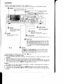
CENTRALIZED DISPLAY
n Ft ,-t t-t BE
11 11
tla
l@l
lml
i_l t_t
2()8
c
p
?
-Mo ilttü
3
rffiilFffia
3
[E-äIT] rä-Fl
lE-o P---ffi7tFi-]
lotl58+
ro4tYrG
RESET
It---------------r
f)
STOP
-
r-TF---.l
rdft-l
FLI'ORESCE}IT PEAK IETER
UI€AR COI'{TER
COUNTER iGII,ORY
lfitfi
rrf€
[0 E nrffiitmrEalErfl
DOLBY
- oll
IFil
START IäIORY./REF
ll--rll-l
Ifi
B-
Fil
mCml
Tf,XFA-TER
ott I
|-il
ltollToR
TAPE I
sor.RcE
r
Operation of the Linear Tape Gounter
( 1 ) Press the RESET button first to set the counter "OOOO".
(2) Tape passage is counted in minutes and seconds during PLAY, FF, and REW modes.
Note
There may be errors between the counter indication and the real recording time. This is
inevitable to some extent due to the fact the counter indicates time during FF and REW as
well as during recording and playback. The degree of error is different for different tapes.
r When the power switch is turned "off", the counter display turns off. When the deck is
turned back "on", the counter is automatically reset to "0OOO", The reading of this counter
does not correspond with that of any other deck.
2)
Operation of MEMORY STOP
1) During recording or playback operations, MEMORY STOP can be used to locate, a particular point on the tape. At the desired point, reset the counter to "OOO0". Wlth the
MEMORY STOP button in the " on " position, the deck will stop at the " OOOO " point
(actually between "9955" and "OOO1") during REWIND operations.
(2) The MEMORY STOP indication will light when this function is activated.
(3) Notes: oWhen the power is turned "off", this function is automatically cancelled.
oThe MEMORY STOP is accurate to -5 on the counter, and will stop between
"9955" and "OOOO"
(
3)
Display Functions
( 1) The position of the tape in use is displayed automatically. NORMAL, CrOz, or METAL
indicators light in the display. A special indicator on the bar-graph level meter shows
the limit of the upper region of the recommended recording level for each type of tape.
The position of this indicator changes according to the type of tape in the deck. For
NORMAL position tapes, the indicator is at the +1 dB point; for CrO, position tapes,
the indicator is at +3 dB; and for METAL position tapes, the indicator is at +5 dB.
ln addition to the level indication, the meters also feature auto peak hold for easy and
precise setting of recording levels.
(2) lf a blank space is to be made during recording, hold the PAUSE/MUTE key in. At this
time, the PAUSE/MUTE indicator in the display will flash in one-second intervals.
(3) The display features two-color lettering and indications for easy identification.
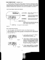
PROPER RECORDING LEVEL
A too high recording level can saturate the tape and cause distortion. On the other hand,
recording levels are set too low, soft passages will be marked by residual noise. Proper
recording level is the single most important factor for making well balanced recordings.
if
- 14-
f
The tape select indicator adopted on this deck displays the tape type (NORMAL, CrOz, METAL)
in words. Also, a bar graph indicator shows the maximum recording level. Recording input
levels can be set by matching with the reading of the PEAK LEVEL METER.
Table
:
Guideline
for maximum recording
Normal tape
* I dB levels on
CrO2 tape
+3
dB levels on peaks
Metal tape
+5
dB levels on peaks
level
Note
peaks
:
Optimum recording levels can dif fer depending
on program sources or the type of tape used.
Make trial recordings using the simultaneous.
monitoring. Refer
,.MONITOR
to the
SWITCH''.
description under
OFor input levels between -1dB and +8d8, the Auto Peak Hold feature holds the peak level
on the meter for approximately 1.5 seconds for easier reading.
OMeter reading difference between L and R channels
The left and right channel readings of the FL PEAK METER can differ in average due to
variations in input signal levels. ln such cases, adjust the individual channels of the INPUT LEVEL
controls until equal meter readings are obtained for both channels.
:
(DR-M33HX only)
RECORDING BIAS FINE ADJUSTMENT
,l
For best recording results, monitoring during the recording process and comparing various
recordings using your own judgement are essential.
The DR-M33HX is equipped with a bias fine adjustment control to assist you in setting the
optimal bias for different types and brands of recording tape. At the center-stop position,
I
j
3
the deck is set for a reference bias level for CrOz and NORMAL tapes. lf the resulting
recording in this position has too much or too little high frequency content, varying the bias
fine adjustment control can be useful to achieve better results.
lf the high frequencies (treble sounds) are to be boosted, turn the bias control counterclockto decrease bias current. lf distortion is of more concern than high frequency response,
turn the control clockwise to increase bias current. By the use of this control, you can
record tapes with response that matches your personal listening tastes.
wise
6
!
BIAS TINE AOJ
aa
a
J
U
U
J
t-
=
o
F
=
o
fl
FREQUENCY ( Hz)
MONITOR SWITCH
This Stereo cassette deck uses a three-head system which permits simultaneous " off
-
fl
the-tape monitoring" during recording. Use the MONITOR switch to select monitcring sources.
The MONITOR indicator shows the selected monitoring source, "TAPE" or "SOURCE".
Monitor Switch
Rac
Recordlng
.
B
"TAPE(I }"
enables you easy check for optimum recording
levels. ln the "TAPE" mode, the FL PEAK METER
indicates the signal levels played back off.the.tape.
H.d
Monitor Switch i"SOURCE(-)"
Monitor Switch r) "TAPE ( f
\
Playback
lop.
--Tn,,,""
--r
f
The signal recorded on the tape is monitored simul'
taneously "off-the-tape". This monitoring mode
t
L-DHourput
)
The SOURCE position enables you to monitor the
input source signal before it is recorded on the
tape. Using the FL PEAK METER, this mode is
convenient for setting recording levels or input
leVel monitoring during recording.
During playback, the MONITOR switch must be
placed in the TAPE posision. lf it is set in the
SOURCE position, the signal f rom the tape won't
be heard.
-15-
'
*
.:
8*g
,*i
rTIMER RECORDING/PLAYBACK
I
I
i
Timer recording/playback can be made using any audio timer avaitable on the market.
Tuner
Stereo cassette deck
I
L---_---------
---------l
Timer
Speaker System
Fis. 13
r Timer recording procedure
1. Make sure the connections are
I Timer playback procedure
1. Make sure the connections
2.
2.
3.
4.
5.
6.
7.
8.
9.
correct,
especially the power supply connections.
Turn " on " the power switch of each appliance.
Tune the desired station on the tuner.
Load the tape for recording. (Make sure
the erase prevention tab is not broken off;
if it is, cover the hole with plastic tape).
Set the Dolby NR switch to the appropriate
position.
Press the monitor switch
Position (
to the
SOURCE
^ ).
Adjust the recording input level.
Set the starting position of the tape.
Set the timer switch (TIMER) to the "rec"
side.
10. Set the audio timer to the desired time.
The audio timer will turn the power supply
on at the desired time.
*With the above procedures, timer controlled
recording can be made. When the preset time
comes, the power is supplied and the FM
broadcast can be recorded.
Note:
. When making Dolby NR encoded recordings from
FM broadcast, set the Dolby NR switch to either
B or C. Push the MPX FILTER switch on ( r ).
. When the power supply is turned " on " with the
timer switch is set to the " rec " side, the auto
tuning system will operate first. The EQ and the
sensitivity will be automatically adjusted for the
3.
4.
5.
6.
7.
8.
pliance.
Load the pre-recorded tape
back.
to be played
Set the Dolby NR switches to the apiropriate positions.
Set the monitor switch to the TAPE ( r )
position.
Press the PLAY ( > ) key and playback
the tape; adjust the playback level.
Set the timer switch (TIMER) to the "play"
side.
Set the audio timer to the desired time.
The audio timer will turn the power supply
on at the desired time.
*With the above procedures, timer playback
can b'e accomplished. When the preset time
comes, the power is supplied and playback
will start.
Note:
. Please read the operating instructions
tape being used. When the adjustme4;fs are
completed, the tape will be rewound to the point
. where the auto tuning was started, followed by the
start of recording. When setting the timer, always
remember to allow some time for the auto tuning
system to operate. (DR-M44HX only)
-15-.t
are correct,
especially the power supply connections.
Turn "on" the power switch of each ap-
for
the
timer before use.
. lf the timer recording or playback is not desired,
be sure to switch the timer switch (TIMER) to
"oft".
. When using timers that allow several " onloff "
operations, timer start functioning can continue
an unlimited number of times until the tape in
the machine is finished.
PAUSE/MUTE KEY
This is an original feature developed by DENON. lt enables bottr pause functioning during
playback as well as pause and mute functioning during recording operations. lt is especially
convenient for adding non-recorded intervals (blank spaces) between selections being recorded.
l.
By continuously pressing the PAUSE/MUTE key during recording, non-recorded interval
(blank space) will be recorded on the tape.
2.
When the PAUSE/MUTE key is released during recording, the deck reverts
3.
To restart recording (or playback), push the PLAY key.
ing standby mode.
Note
When using this function during playback, refer to page 10.
When using this f unction during recording, ref er to page 11.
to the
record-
Fig. 14
DOLBY HX.PRO HEADROOM EXTENSION SYSTEM
This deck is equipped with the DOLBY HX-PRO headroom extension system. Since the system
functions automatically during recording, no switching operation or adjustment is required.
The system is effective with any type of Normal, CrOz or Metal tapes.
The Dolby HX-PRO headroom extension system functions during recording to lift up the
saturation level in the treble range. Therefore, most of the treble range components distorted
or lost during recording on conventional cassette decks are more faithfully recorded on the
new DR-M33HX/M44HX cassette deck.
Features of the DOLBY HX-PRO headroom extension system
1)
(2)
(3)
(
(4)
Performance of Normal and CrO, tapes can be up-graded closer to that of Metal tapes.
The dynamic range in the treble is. improved signif icantly.
Since no decoding in playback is necessary, the improvement can be obviously heard on
any hi-fi playback system including portable components and car systems.
The system functions whether the Dolby B/C NR is engaged or not.
DOLBY C NOISE REDUCTION SYSTEM
r
The Dolby noise reduction system substantially reduces the tape background noise (hiss) in'
herent in the cassette medium. Dolby B NR is most widely in use. However, Dolby C NR is
a much more recent development and represents a signif icantly improvement over Dolby B NR.
rTape background noise consists primarily of high freqnency information which is particularly
annoying during soft passages. The Dolby NR system increases the level of low volume mid
and high frequency signals during recording and reduces the level of these signals by an identical
amount during playback. As a result, the playback signal is identical to the original source
signal, but the level of background noise generated by the tape is greatly reduced.
r
The operating principle of Dolby C NR is similar to that of B except for the encoding/decoding
response curves. The noise reduction effect obtained by Dolby C NR is up to 2OdB, compared to
lOdB with Dolby B NR. ln addition, Dolby C NR uses an antisaturation network and spectral
skewing circuitry, and significantly improves the dynamic range in the mid to high frequencies.
-17-
Fis. 15
MAINTENANCE
r
Removing the cassette compartment cover
It will be more convenient if the cassette
compartment cover is removed during the
cleaning of the pinchroller and heads, or during
demagnetizing of heads.
Follow these procedures:
1. Press the EJECT button to open the cassette
compartment.
2. Hold only the cover of the cassette
com-
partment'and pull it up. The compartment
cover is removed from the front. (Fig. 17)
3.
Fig. 17
Replace and lock the cassette compartment.
Tlie heads and the pinchroller will be easily
accessible.
When attaching the. cassette compartment
cover, reverse the above procedure.
r
Head Gleaning
After long usage, tapp coating or dust may
adhere to the heads causing deterioration of
sound. Clean them regularly. Use a cotton
swab moistened with cl'eaning solution (such
as alcohol). (Fig. 18)
Note:
1.
2.
Some cleaning cassettes on the market have
strong abrasive effect and scratch the
heads. Use cotton swabs instead of cleaning
cassettes.
Since the use of metal tapes is apt to collect
a
more dust on the heads, clean the heads
more often to enjoy optimum sound.
r Cleaning the pinchroller
and the capstan
lf the pinchroller or the capstan accumulate
dust, tape transport may become unstable
resulting from slippage during recording or
playback. The tape can also be dartläged by
being rolled up around the capstan.
Clean them with a cotton swab or a soft
cloth moistened with cleaning solution (such
as atcohot). (Fie. 19)
-18-
Fig. 19
I Demagnetizing
the heads
The heads may become magnetized after long usage or by having a-strongly magnetized object
brought near them. The result is a generation of noise, loss of thä high frequency range, or
erasing the treble components of pre-recorded tapes and adding noise.
Demagnetize the heads on a regular basis.
I Procedure
1.
2.
3.
Be sure to turn "off" the power supply.
Turn .the demagnetizer "on" while it is more than 3Ocm away from the heads. Bring the
demagnetizer near the heads and slowly move it in a small circle four or five times.
Slowly move the demagnetizer away from the heads and turn "off" the power of the de.
magnetizer when it is about 30cm away from the heads.
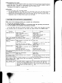
SYMPTOMS OFTEN MISTAKEN AS BREAKDOWNS
Make sure of the followings before you consider any malfunctions :
1. Are all the connections correct?
2. ls the set being operated correctly in accordance with the operating instructions?
3. Are the speakers and amplifiers functioning correctly?
.
lf the tape deck still does not function properly, check it again, using the check list below.
lf the symptom does not correspond to the check list, please contact your DENON dealer.
Symptom
Cause
Tape does not run
Remedy
Power cord is off.
Tape is completely wound up.
Tape is loose.
Cassette is not loaded properly.
Defective cassette.
Tape is not recorded No cassette is loaded.
when recording button Erase prevention tab is broken off
is
pressed.
Sound is warbled or
istorted.
d
Heads, capstan or pinchroller are con.
taminated.
Tape is wound too tight.
Tighten tape with pencil, etc.
Load cassette properly.
Replace cassette.
Load cassette.
Cover hole with plastic tape.
Clean them.
Tape is worn out and has "drop.outs".
to loosen tape
winding.
Adjust recording input level.
Replace tape.
Tape is worn.
Heads, capstan or pinchroller are con-
Replace tape.
Clean them.
Recording input level is too high.
Excessive noise.
Check power cord.
Rewind tape.
Fast forward or rewind
taminated.
Heads are magnetized.
Recording input level is too low.
Demagnetize heads.
High f requency(treble)
is emphasized.
Dolby NR switch is set improperly.
Set Dolby NR switch properly.
High f requency(treble)
is lost.
Heads are contaminated.
Tape is worn.
Clean them.
Replace tape.
Auto tuning is inoper.
ative(DR-M44HX only)
Erasure prevention tab is removed.
Cover the erasure prevention tab hole
Adjust recording input level.
with plastic tape.
or metal The cassette housing is of an older Use the latest cassettes with tape type
tape is placed in the
design without tape type detection
detection holes.
deck, a different tape
holes.
When a CrOz
indicator comes on.
The cassette
tape
cannot be removed.
lf the
power switch is tu'ned off in Turn the power switch ON again,
then press the stop ( f ) t<ey.
eithei the recording or pfayback mode,
and
and the unit is stopped, there may be Then, in the stop mode, press the
EJECT button to remove the cassette
cases when the cassette cannot be
removed, even if the EJECT button is
pressed.
- l9-
tape.