1
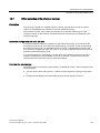
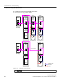
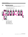
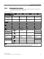
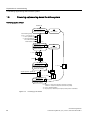
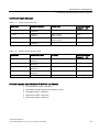
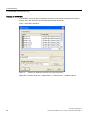
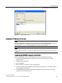
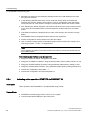
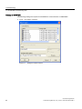
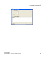
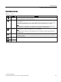
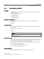
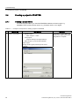
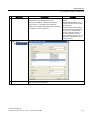
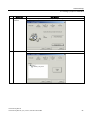
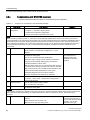
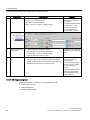
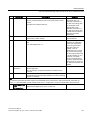
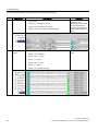
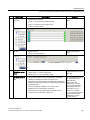
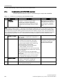
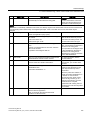
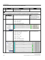
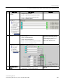
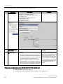
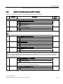
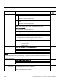
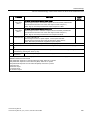
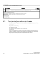
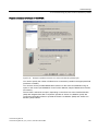
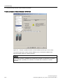
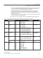
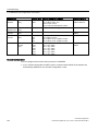
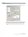
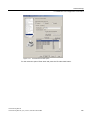
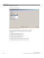
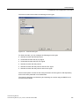
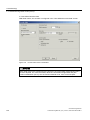
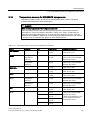
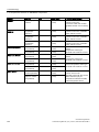
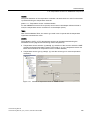
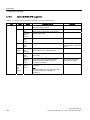
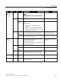
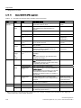
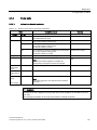
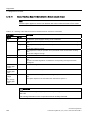
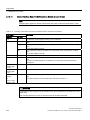
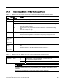
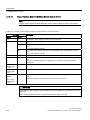
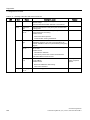
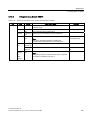
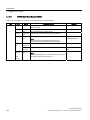
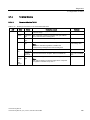
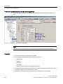
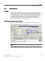
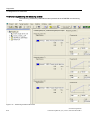
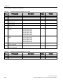
Commissioning 2.7 First commissioning, vector control mode in the chassis format What to do? How to do it? Comment 6. Motor temperature Thermistor selection: via Motor Module (11) Temperature sensor type: KTY84 (2) Response to overtemperature: alarm and fault (no reduction of Imax) Fault message for thermistor failure: ON Deceleration time: 0.100 s Alarm threshold: 120.0° C Fault threshold: 155.0° C 7. Save the parameters on the device Target device -> Copy from RAM to ROM Position cursor on drive unit and right-click. 8. The motor starts to run. The drives can be started via the control panel in STARTER. For more information about the control panel, see Getting Started. Line/DC link identification will be carried out once the pulses for the infeed have been enabled and line/DC link identification has been activated. The infeed then switches to operational mode. When the pulses are enabled, a one-off motor data identification run (if activated) is carried out. When the pulses are enabled again, optimization with a rotating motor (if activated) is carried out. During motor data identification, a current flows through the motor, which means that it can align itself by up to a quarter of a revolution. For more information about line/DC link/motor data identification, see the SINAMICS S120 Function Manual. Diagnostics parameters (see the SINAMICS S120/S150 List Manual) ● r0002 Infeed/drive operating display ● r0046 Missing enable signals (for more information, see "Diagnostics") Commissioning Manual 104 Commissioning Manual, (IH1), 01/2011, 6SL3097-4AF00-0BP1