1
SD16 Series
Digital Indicator
Instruction Manual
Thank you for purchasing the Shimaden SD16 Series. Please check that the delivered product is the correct
item you ordered. Please do not begin operating this product until you have read this instruction manual
thoroughly and understand its contents.
Notice
Please ensure that this instruction manual is given to the final user of the instrument.
SD16F-1BE
Apr. 2001
CAUTION
Preface
Regarding the alert symbol mark
on the plate attached
to this instrument:
On the terminal nameplate attached to the case, an alert
symbol
is printed. This is to give a caution not to
touch the electrical charging part when power is being
supplied so as to avoid the risk of electrical shock.
Install a switch or breaker on the external source power
circuit connecting to the source power terminal as a means
of shutting down the power.
The switch or breaker should be installed adjacent to the
instrument at a position which allows easy access of the
operator. Put up a sign indicating that this switch is for
shutting down the power of the instrument.
Regarding the fuse:
Since this instrument has no built-in fuse, make sure to
install a fuse in the electric circuit connecting to the source
power terminal.
Install the fuse at a position between the switch or breaker
and the instrument and attach it to the L side of the source
power terminal.
Fuse Rating: 250V AC 1.0A/Time-lag(T), Low-breaking
capacity (L)
Use a fuse which meets the requirements of IEC127.
The load of voltage and current to be applied to the output
terminal (analog output) and the alarm terminal have to be
within the rated range. If the range is exceeded, the
instrument will overheat and, as a result, there is a risk of
the instrument being damaged and the life reduced.
As for the rating, please refer to "7. Specification" on page
8.
The unit connected to the output terminal should conform to
the requirements of IEC1010.
Do not apply over-rated voltage or current to the input
terminal. There is a risk of the instrument being damaged
and the life reduced.
As for the rating, please refer to "7. Specification" on page
8.
In case the input type is voltage (mV or V) or current (4 ~
20mA), the unit connected to the output terminal should
conform to the requirements of IEC1010.
The instrument has a ventilating hole for heat radiation.
Take care to prevent metal or other foreign matter from
obstructing it. It will cause damages to the instrument and
may even result in fire.
Do not block the ventilating hole. Also avoid dust
accumulation. Any rise in temperature or insulation
failure may result in a shortening of the life of product
and/or problems with the product. As for the clearance
space for installing the instrument, refer to "2-3 External
dimensions and panel cutout" on page 4.
Repeating withstanding tests on voltage, noise, surging may
lead to deterioration of the instrument. Please be careful.
Strictly refrain from remodeling and using the instrument
improperly.
This instruction manual is meant for those who will be involved in
the wiring, installation, operation and routine maintenance of the
SD16 series.
This manual describes items concerning safety cautions,
installation, wiring, functions and operating method for SD16
series. Always keep this manual close at hand when handling this
instrument.
Please observe the descriptions in this manual whenever you use
this instrument.
Matters of attention concerning safety, damages on machines and
equipment, additional explanations and commentaries are
described under the following headings.
WARNING
Items concerning matters that may lead to an accident involving
human injury or death, if the warning is not observed.
CAUTION
Items concerning matters that may lead to an accident involving
damages to machines or equipment, if the caution is neglected.
Note
Additional explanations and commentaries.
expresses the terminal of protective conduction.
The symbol
Please make sure to arrange wire connection for grounding.
Safety Cautions
WARNING
SD16 series indicator is designed to indicate temperature,
humidity and other physical data of general industrial
equipment. Do not apply this instrument to other objects in a
way that may give grave effects on safety of human life. For
such uses involving possible risks, proper safety measures have
to be provided. In case of an accident by operation without
safety countermeasures, sellers shall not take any
responsibility.
WARNING
• In using this product, be certain to house it, for example, in
a control panel so that the terminals cannot come into
contact with personnel.
• Do not take this instrument out of the case or put your hand
or any conductor inside the case. Such conduct may lead to
an accident which endangers life or causes serious injury
due to electric shock.
• Do not fail to ground the earthing terminal in use.
CAUTION
To avoid damage to the connected equipment, facilities or the
product itself due to a fault of the product, safety countermeasure must be taken before usage, such as proper installation of
the fuse and the overheating protection device. No warranty,
express or implied, is valid in the case of usage without having
implemented proper safety countermeasures.
-2-
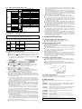
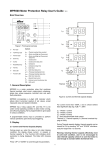
SD16- 8
90-
0 0
0
0
Item
Reference code and contents
CONTENTS
Page
1. Introduction............................................................................ 3
1-1. Check before use ............................................................. 3
1-2. Caution for use ................................................................ 3
2. Installation and wiring .......................................................... 3
2-1. Installation site (environmental conditions) .................... 3
2-2. Mounting ......................................................................... 3
2-3. External dimensions and panel cutout ............................. 4
2-4. Wiring.............................................................................. 4
2-5. Terminal arrangement...................................................... 4
2-6. Terminal arrangement table ............................................. 4
1. Series
SD16 : 48 × 96 DIN size
2. Input
8: Multi-input, thermocouple,
Voltage (mV, V), Current (mA)
3. Power supply
90-: 100 – 240V AC ±10% (50/60Hz)
08-: 24V AC (50/60Hz)/DC ±10%
4. Alarm (option)
0: None
Digital Indicator
R.T.D.,
1: Alarm output
5. Analog output (option)
0: None
3: 0~10mV DC (output resistance 10 Ω)
4: 4~20mA DC (load resistance 300 Ω max.)
6: 0~10V DC (load current 1mA max.)
6. Communication (option)
0: None
5: RS-485
7: RS-232C
7. Remarks 0: Without
3. Instruction for front panel..................................................... 4
3-1. Front illustration and the name of parts ........................... 4
3-2. Instruction for front panel................................................ 4
9: With
Accessory list check:
Instruction Manual
1 copy
Unit decal
1 sheet
Communication Instruction Manual
1 copy
(In case of optional communication selected)
4. Explanation of each screen .................................................... 5
4-1. List of screen sequence.................................................... 5
4-2. Mode 0 screen group ....................................................... 6
4-3. Mode 1 screen group ....................................................... 6
4-4. Table of measuring range code ........................................ 7
4-5. Table of alarm type code ................................................. 7
4-6. Method of shifting screens .............................................. 7
Note: Contact our representative concerning any problems
with the product, accessories or related items.
1-2. Caution for use
(1) Avoid operating keys of the front panel with hard or sharp
objects or motions. Lightly touch the operating keys with
finger tip for operation.
(2) When cleaning, do not use solvent like thinner. Wipe the
instrument with dry cloth lightly.
5. Supplementary explanation................................................... 7
5-1. Display update cycle (Screen No.1-2) ............................. 7
5-2. Alarm output action (option) ........................................... 7
5-3. Analog output action (option) ......................................... 7
5-4. Auto-return function........................................................ 7
2. Installation and wiring
6. Error message......................................................................... 7
2-1. Installation site (environmental conditions)
7. Specification ........................................................................... 8
CAUTION
Do not install the instrument at a place of environmental
conditions as listed below. Otherwise, it will cause damages
to the instrument and may even result in fire.
1. Introduction
1-1. Check before use
The instrument passes thorough quality checks before shipment.
When the instrument is delivered, please confirm the type code
number, then check the external conditions and the list of
accessories. Make sure that there are no apparent damages or
discrepancies.
Confirmation of the type code: Collate the type code printed on the
label attached to the packing case with the following schema and
confirm that the delivered goods meet your order.
(1) Where flammable or corrosive gas, oil soot or dust that
deteriorates insulation is generated or abundant.
(2) Where ambient temperature is below −10°C or above 50°C.
(3) Where ambient humidity is higher than 90% RH, or below dew
point.
(4) Where strong vibrations or impact is generated or transferred.
(5) Where there is a high-tension electrical circuit in the
neighborhood, or induction interference.
(6) Where under exposure to direct sun light or dew drops.
(7) Where the elevation is higher than 2000m.
(8) Outdoors
Note: The environmental conditions belong to the installation
category II of IEC 664 and the degree of pollution is 2.
2-2. Mounting
(1) Cut a fitting hole by referring to the panel cutout plan in item
2-3.
(2) Applicable thickness of the panel is 1.0 ~ 4.0mm.
(3) The instrument has catching claws to fix it in position.
Just push it in from the front panel.
Note: SD16 is a panel installation type indicator. When the
instrument is used, make sure to mount it on a panel.
-3-
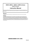
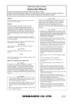
2-6. Terminal arrangement table
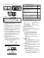
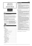
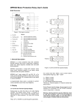
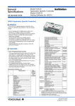
2-3. External dimensions and panel cutout
SD16 External dimension
111
100
11
96
Name of terminal and contents
44.6X91.6
AL1
48
AL2
SET
COM
ENT
SD16
SD16 Panel cutout
60min.
45+0.6
0
92+0.8
0
110min.
(Unit : mm)
2-4. Wiring
WARNING
(1)
(2)
(3)
(4)
(5)
(6)
(7)
(8)
(9)
(10)
(11)
When making wire arrangement, be sure to cut the power
supply OFF. There is a risk of electric shock.
Make sure the protective conductor terminal ( ) is
grounded. Otherwise, a serious electric shock may result.
After completing wiring arrangement, do not touch the
terminals and electrically charged parts while power is ON.
Arrange wiring according to the terminal layout in item 2-5
and the terminal arrangement table in item 2-6. Confirm
that all connections are made correctly.
Use crimp-style terminals of 7mm or narrower width to meet
M3.5 screws.
In case of thermocouple input, use a compensation wire with
the type of thermocouple selected. The external resistance
should be100 Ω or less.
In case of R.T.D. input, the resistance value per lead wire
should be 5 Ω or less and all the 3 wires should have the same
resistance value.
Avoid arranging the input signal line to pass through in the
same conduit or duct with high-tension circuit.
Shield wire (one-point grounding) is effective to eliminate
the electrostatic induction noises.
An effective way of eliminating the magnetic induction
noises is to twist the input wire in short and equal intervals.
For source power connection, use wire or cable having a
cross section of 1mm2 or larger and performance capacity
equivalent to 600V vinyl insulation wire.
Grounding wire should have a cross section of 2mm2 or
larger and the grounding work should ensure ground
resistance of 100 Ω or less.
Screw up the terminal connection securely.
Tightening torque 1.0N·m (10kgf·cm)
Noise filter
In case the instruments are affected by the power supply
noise, install a noise filter to avoid operation errors.
Mount the noise filter on the grounded panel and connect the
noise filter output and the power supply terminal of the
indicator with shortest possible distance.
11
12
13
SD
RD
+
-
+
-
17
18
19
14
15
16
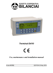
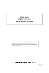
Name of each part
1 Display part for measured
value
2 LED for monitoring
3 Key switch operating part
3-2. Instruction for front panel
1 : Display part for measured value (red)
Mode 0, Current PV value is displayed on the basic screen.
Type of parameters is displayed on each parameter
character screen.
Set value is displayed on each parameter setting screen.
2 : LED for monitoring
(1) AL1 (Alarm 1) output monitoring LED (red)
LED lights when an assigned alarm is ON.
(2) AL2 (Alarm 2) output monitoring LED (red)
LED lights when an assigned alarm is ON.
(3) SET (parameter setting) monitoring LED (green)
LED lights when screen display is other than the basic
screen.
(4) COM (communication) monitoring LED (green)
LED lights when communication mode is on remote
control.
3 : Key switch operating part
(1)
(Parameter key)
By pressing this key, display changes from a screen to
the next in each screen group.
By pressing this key for 3 seconds or longer, the key
works as the shifting key to shift the screen from the
basic screen of Mode 0 screen group to the initial
parameter screen of Mode 1 screen group.
(2)
(down) key
By pressing this key on each screen, the decimal point
of the last digit blinks and the data value is decreased
or the decimal point shifts downward.
(3)
(up) key
By pressing this key on each screen, the decimal point
of the last digit blinks and the data value is increased or
the decimal point shifts upward.
(4) ENT (entry/register key)
This key works for mutual shifting between the
parameter character display screen and the parameter
setting screen. (when light of the decimal point of the
last place is OFF)
On each screen of Mode 0 and Mode 1 screen groups,
the data changed by the
or
key is
established. (when light of the decimal point of the last
place is also OFF)
20
mA (250Ω register
!
24V DC 7W
/24V AC ~
+
-
V
-
L 50/60Hz N
2
3
B
B
+ mV + T.C. -
100-240V AC
1
attached externally)
R.T.D.
R.T.D.
A
+
4
5
6
7
8
9
11
12
13
15
16
17
18
19
3-1. Front illustration and the name of parts
Communication Analog output
RS-485 SG
5
6
7
9
3. Instruction for front panel
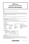
2-5. Terminal arrangement
RS-232C SG
3
Note: In case of thermocouple, voltage and current input,
keep terminal No. 9 open.
Recommended noise filter: TDK product ZMB2203-13
AL1 AL2
Power supply terminal
100 − 240V AC ± 10% 50/60Hz 11VA
24V DC 7W/24V AC ± 10% 50/60Hz 11VA
Protective conductor terminal ( )
Input terminal
Voltage (V)· Current: +
R.T.D. A, thermocouple/voltage (mV): +
R.T.D. B, thermocouple/voltage (mV, V)· current: −
R.T.D. B
Alarm output (option) terminal
COM contact point rating 240V AC, 1.5A (load
resistance)
AL1
AL2
Communication (option) terminal SG, SG
SD, +
RD, −
Analog output (option) terminal
+
−
Terminal
No.
1-2
10
-4-
4. Explanation of each screen
4-1. List of screen sequence
Alarm
-5-
4-2. Mode 0 screen group
Alarm 1 hysterisis
Initial value: 5 unit,
Setting range: 1 ~ 999 unit
This screen is for setting Alarm 1 hysterisis.
In case of the system without alarm option, this screen is
not displayed.
Basic screen
Current PV value is indicated.
PV bias value setting screen
Initial value: 0 or 0.0, Setting range: −200 ~ 200 unit
Used for compensating input errors by sensor, etc.
When bias is applied, compensated PV indication value is
displayed.
Alarm 2 code
Initial value: LL__
Selected from alarm type code table in item 4-5.
In case of the system without alarm option, this screen is
not displayed.
PV filter time setting
Initial value: 0 second
Setting range: 0 ~ 100 seconds
Used for reducing the effect of excessive input fluctuation
and repeating noise.
Alarm 2 hysterisis
Initial value: 5 unit, Setting range: 1 ~ 999 unit
This screen is for setting Alarm 2 hysterisis.
In case of the system without alarm option, this screen is
not displayed.
Analog output lower limit value scaling
Initial value: Measuring range lower limit value
Setting range: Lower limit ~ higher limit of measuring
range
Setting of lower limit value of analog output scaling is
made.
Span with higher limit value = 1 count
Reverse scaling is possible.
In case of the system without analog output option, this
screen is not displayed.
For details, refer to item 4-6 (5).
Alarm 1 level setting screen
This screen is displayed when the following setting code is
selected on the code selection screen of Mode 1 setting
screen. On this screen, setting of alarm action point is
available.
In case of the system without alarm option, this screen is
not displayed.
Alarm type
Higher limit
Lower limit
Code
HL__, HL_S
LL__, LL_S
Initial value
Higher limit value
Lower limit value
Setting range
Within range
Within range
Analog output higher limit value scaling
Initial value: Measuring range higher limit value
Setting range: Lower limit ~ higher limit of measuring
range
Setting of higher limit value of analog output scaling is
made.
Span with lower limit value = 1 count
Reverse scaling is possible.
In case of the system without analog output option, this
screen is not displayed.
For details, refer to item 4-6 (5).
Alarm 2 level setting screen
Same as the above Alarm 1 setting screen
4-3. Mode 1 screen group
Parameter initial screen
This is the heading screen of Mode 1.
Key lock mode setting screen
Initial value: OFF,
Setting range: OFF, ON
When key lock ON is set, data is protected and cannot be
changed.
Communication mode
Initial value: Loc (local), Setting range: Loc, Com
Communication mode is set.
Front key operation can change Com → Loc only.
For details, refer to separate Instruction Manual for
communication.
In case of the system without communication option, this
screen is not displayed.
Indication renewal time setting screen
Initial value: 0.5 second
Setting range: 0.5 ~ 5.0 seconds
Setting of the time of renewing PV value indication is made
on this screen. Time is set by every 0.5 second.
Measuring range selecting screen
Initial value: 05
Setting is made by selecting the code from the measuring
range code table in item 4-4.
Communication address
Initial value: 1,
Setting range: 1 ~ 255
When plural machine is connected, the number of the
machines is set.
For details, refer to separate Instruction Manual for
communication.
In case of the system without communication option, this
screen is not displayed.
Input unit setting screen
Initial value: °C,
Unit selection: °C or °F
The input unit is selected.
In case of linear input (mV, V, mA), this screen is not
displayed.
Communication data
Initial value: 7E1,
Setting range: 7E1, 8N1
Setting of communication data format is set.
For details, refer to separate Instruction Manual for
communication.
In case of the system without communication option, this
screen is not displayed.
Input scaling decimal point position
Initial value: 0.0
Setting range: No decimal point, 0.0, 0.00, 0.000
The decimal point setting is made at the time of linear input
(mV, V, mA) scaling.
For sensor input, this setting is not possible, where
monitoring only will do.
Start character
Initial value: STX,
Setting range: STX, ATT
The character at the head of communication is set.
For details, refer to separate Instruction Manual for
communication.
In case of the system without communication option, this
screen is not displayed.
Input scaling lower limit
Initial value: 0.0, Setting range: −1999 ~ 9999 units
The lower limit value setting is made at the time of linear
input (mV, V, mA) scaling.
The span with the higher limit = 10 ~ 5000 counts
Reverse scaling is possible.
For sensor input, this setting is not possible, where
monitoring only will do.
For details, refer to item 4-6 (4).
Communication speed
Initial value: 1200bps
Setting range: 1200, 2400, 4800, 9600, 19200bps
Transmitting speed of communication data is set.
For details, refer to separate Instruction Manual for
communication.
In case of the system without communication option, this
screen is not displayed.
Input scaling higher limit
Initial value: 100.0
Setting range: −1999 ~ 9999 units
The higher limit value setting is made at the time of linear
input (mV, V, mA) scaling.
The span with the lower limit = 10 ~ 5000 counts
Reverse scaling is possible.
For sensor input, this setting is not possible, where
monitoring only will do.
For details, refer to item 4-6 (4).
Delay time
Initial value: 80,
Setting range: 0 ~ 500
The delay time from receipt of communication command
till starting transmission is set.
Delay time = 0.1 × Setting value (in milli-second)
For details, refer to separate Instruction Manual for
communication.
In case of the system without communication option, this
screen is not displayed.
Alarm 1 code
Initial value: HL__
Selected from alarm type code table in item 4-5.
In case of the system without alarm option, this screen is
not displayed.
-6-
limit value is set with a difference less than 10 counts from that of the higher
limit value, the lower limit value is forcibly changed to a new value at higher
limit value plus 10 counts.
As a result, when the lower limit exceeds 9999 counts, it is changed to the
value of the higher limit value minus 10 counts. Also, when the higher limit
value is set at a value with a difference exceeding 5000 counts from the lower
limit value, the lower limit value is forcibly changed to a new value at higher
limit value plus 5000 counts (−5000 counts).
(5) Method of setting analog output scaling screen in Mode 1 screen group
On condition that "Lower limit value < Higher limit value", when the lower
limit value is set at the same value of the higher limit, the higher limit value is
automatically changed to the lower limit value +1 count. As a result, when
the higher limit exceeds the higher limit of the measuring range, it is changed
to the value of lower limit −1 count.
On condition that "Lower limit value < Higher limit value", when the higher
limit value is set at the same value of the lower limit, the lower limit value is
automatically changed to the higher limit value −1 count. As a result, when
the lower limit exceeds the lower limit of the measuring range, it is changed to
the value of higher limit +1 count.
On condition that "Lower limit value > Higher limit value", when the lower
limit value is set at the same value of the higher limit, the higher limit value is
automatically changed to the lower limit value −1 count. As a result, when
the higher limit exceeds the lower limit of the measuring range, it is changed
to the value of lower limit +1 count.
On condition that "Lower limit value > Higher limit value", when the higher
limit value is set at the same value of the lower limit, the lower limit value is
automatically changed to the higher limit value +1 count. As a result, when
the lower limit exceeds the higher limit of the measuring range, it is changed
to the value of higher limit −1 count.
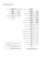
4-4. Table of measuring range code
Input type
Thermocouple
R.T.D.
B
R
S
K
K
E
J
T
N
*1
U
*1
L
*2 WRe5-26
Pt100
Code
Measuring range
°C
°F
0
~ 1800
0
~
0
~ 1700
0
~
0
~ 1700
0
~
−199.9 ~ 800.0 −300
~
0
~ 1200
0
~
0
~ 700
0
~
0
~ 600
0
~
−199.9 ~ 300.0 −300
~
0
~ 1300
0
~
−199.9 ~ 300.0 −300
~
0
~ 600
0
~
0
~ 2300
0
~
−200
~ 600
−300
~
−100.0 ~ 100.0 −150.0 ~
Initial value: 0.0 ~ 100.0
Scaling range: −1999 ~ 9999 count
Span: 10 ~ 5000 count
3300
3100
3100
1500
2200
1300
1100
600
2300
600
1100
4200
1100
200.0
0 ~ 10mV
0 ~ 5V
Voltage
1 ~ 5V
0 ~ 10V
Current
4 ~ 20mA
Thermocouple:
B, R, S, K, E, J, T, N: JIS/IEC
*1 Thermocouple
U, L: DIN43710
*2 Thermocouple
WRe5-26: Hoskins product
R.T.D. Pt100:
New JIS/IEC
Note: When the measuring range is changed, data related to measuring range,
such as set value and alarm setting value are initialized.
5. Supplementary explanation
4-5. Table of alarm type code
5-1. Display update cycle (Screen No.1-2)
Alarm code can be assigned each for AL 1 and AL 2 independently.
*1
Alarm Alarm type Inhibit
Remarks
Communic
action
code
ation
HL__ Higher
No
1
Output ON, also in case of sensor
limit
breakage or higher limit scale-over
Yes
2
HL_S absolute
value
LL__ Lower limit
No
3
Output ON, also in case of lower
absolute
limit scale-over
Yes
4
LL_S value
*1 During communications, Read and Write become possible at the above values.
Setting of PV display update cycle on the basic screen is made.
The setting of value is made every 0.5 second.
5-2. Alarm output action (option)
(1) Setting of alarm higher limit value
For setting the alarm higher limit value, the alarm hysterisis is set by selecting
the higher limit alarm on the alarm code screen of Mode 1 screen group (when
alarm option is attached).
The higher limit alarm is output when the process value exceeds the alarm
level value. The output goes off when the process value comes down below
the alarm level value minus the alarm hysterisis.
(2) Setting of alarm lower limit value
For setting the alarm lower limit value, the alarm hysterisis is set by selecting
the lower limit alarm on the alarm code screen of Mode 1 screen group.
The lower limit alarm is output when the process value comes down below the
alarm level value. The output goes off when the process value exceeds the
alarm level value plus hysterisis.
4-6. Method of shifting screens
(1) Method of shifting between Mode 0 screen group and Mode 1 screen
group
By pressing the
key on the basic screen for 3 seconds or longer,
the display changes to the parameter heading screen of Mode 1
screen group. To return to the basic screen, keep pressing the
key again for 3 seconds or longer.
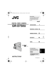
5-3. Analog output action (option)
The analog output is a function that outputs the analog voltage or analog
current corresponding to the process value. They are used for input signal
into a recorder and data accumulation equipment.
Within the measuring range specified by the lower and higher limit value of
the analog output scaling, analog output signal to correspond to the process
value is available.
(2) Method of shifting screen within Mode 0 screen group
By each pressing of the
key, screen shift takes place.
When the light of decimal point of the lowest digit place is OFF, by each
ENT
pressing of
key, the screen shifts alternately between the parameter
character indicating screen and the parameter setting screen.
(3) Method of shifting screen within Mode 1 screen group
By each pressing of the
key, screen shift takes place.
When the light of decimal point of the lowest digit place is OFF, by each
ENT
pressing of
key, the screen shifts alternately between the parameter
character indicating screen and the parameter setting screen.
(4) Method of setting input scaling screen in Mode 1 screen group
On condition that "Lower limit value < Higher limit value", when the lower
limit value is set with a difference less than 10 counts from that of the higher
limit value, the higher limit value is forcibly changed to a new value at lower
limit value plus 10 counts.
As a result, when the higher limit exceeds 9999 counts, it is changed to the
value of the lower limit value minus 10 counts. Also, when a lower limit
value is set at a value with a difference exceeding 5000 counts from the higher
limit value, the higher limit value is forcibly changed to a new value at lower
limit value plus 5000 counts (−5000 counts).
On condition that "Lower limit value < Higher limit value", when the higher
limit value is set with a difference less than 10 counts from that of the higher
limit value, the lower limit value is forcibly changed to a new value at higher
limit value minus 10 counts.
As a result, when the lower limit exceeds −1999 counts, it is changed to the
value of the higher limit value plus 10 counts. Also, when a higher limit
value is set at a value with a difference exceeding 5000 counts from the lower
limit value, the lower limit value is forcibly changed to a new value at higher
limit value minus 5000 counts (+5000 counts).
On condition that "Lower limit value > Higher limit value", when the lower
limit value is set with a difference less than 10 counts from that of the higher
limit value, the higher limit value is forcibly changed to a new value at lower
limit value minus 10 counts.
As a result, when the higher limit exceeds −1999 counts, it is changed to the
value of the lower limit value plus 10 counts. Also, when a lower limit value
is set at a value with a difference exceeding 5000 counts from the higher limit
value, the higher limit value is forcibly changed to a new value at lower limit
value minus 5000 counts (+5000 counts).
On condition that "Lower limit value > Higher limit value", when the higher
Scaling output diagram
5-4. Auto-return function
On any screen other than 0-0 basic screen, if no key operation is made for 3 minutes
or longer, the screen shifts to the basic screen (auto-return).
6. Error message
Abnormal input of process value (indicated on the basic screen of Mode 0 screen
group)
This message is indicated when the thermocouple or A of R.T.D. is
burnt out, also when PV value exceeds the higher limit of the
measuring range by about 10%.
When PV value is below the lower limit of the measuring range by
about 10%, by reason such as wrong polarity of input wiring.
When the Pt B (terminal No.7) wire breaks.
When the cold junction (CJ) is abnormal on the higher side in
thermocouple input.
When the cold junction (CJ) is abnormal on the lower side in
thermocouple input.
When the B wire (terminal No.9) breaks, or when plural number of
wires out of A B B break.
· ·
Note: When abnormality occurs, please contact our sales agent or to our business
office directly.
-7-
7. Specification
Display
Digital display : Process value (PV) 7 segment Red LED 4 digits
Action indication : 1 point of parameter display (SET) by green LED
1 point of communication display (COM) by green LED
2 points of alarm (AL1, AL2) by red LED
Display accuracy : ±(0.3% FS+1 digit) within measuring range
Excluding cold junction temperature compensation accuracy in
the case of thermocouple input
±5%FS for temperature below 400˚C of thermocouple B
When the thermocouple [T, U] indication value is –100 ~ 0˚C,
±0.5%FS and when it is below –100˚C, ±1% FS
Display accuracy : 23˚C ±5˚C (18 ~ 28˚C)
range
Display
: Depends on measuring range (0.001, 0.01, 0.1, 1)
resolution
Measured value : –10 ~ 110% of measuring range (Accuracy guaranteed for value
display range
is within measuring range only)
For R.T.D. input of –200 ~ 600˚C : 210 ~ 680˚C
For thermocouple [K] input of –199.9 ~ 800.0˚C: –273.1 ~
900.0 ˚C
Display update : 0.5 ~ 5.0 seconds (0.5 Steps)
cycle
When 0.5 second or more is set, there may occur a difference
among the displayed value, the analog output and the
communication data.
Setting
Setting
Setting range
Alarm setting
:
range
Alarm action
:
Alarm sensitivity :
Alarm output/ :
rating
Alarm output
:
update cycle
Thermocouple
External
resistance
Input impedance
Burnout
Cold junction
temperature
compensation
accuracy
R.T.D.
Amperage
Lead wire
tolerable
resistance
ON-OFF action
1 ~ 999 unit (within measuring range)
Contact 1a (common) / 240V, AC1.5A (resistive load)
0.5 seconds
Analog output (option)
Analog output : 0 ~ 10mV (output resistance: 10Ω)
type
0 ~ 10V (load current: 1mA max)
4 ~ 20mA (load resistance : 300Ω max)
Output
: Approx. 0.03% (1/3000)
resolution
Output accuracy : ±(0.3%FS + 1 digit) of display value
Output scaling : Within measuring range (inverse scaling possible)
Output update : 0.5 seconds
cycle
Communication (option)
Communication : RS-232C, RS-485
type
Communication : Half duplex start-stop synchronized system
system
Communication : 1200, 2400, 4800, 9600, 19200 bps
speed
Data bit length : 7 bit even parity 1 stop bit
8 bit non parity 1 stop bit
Communication : 1 ~ 255
address
Multi-drop
: 31 max (with RS-485)
connection
Communication : 0 ~ 50.0 milli-seconds
delay
: By four (4) front key switches
: Same as measuring range
Input
Type of input
Within measuring range or within full scaling range
: Multiple input of Thermocouple, R.T.D., Voltage (mV, V) and
Current (mA)
: B, R, S, K, E, J, T, N, {U, L (DIN43710)}, WRe5-26
Refer to measuring range code table.
: 100Ω max.
Others
Data storage
: By non volatile memory (EEPROM)
Ambient conditions for use
Temperature/
: –10 ~ 50˚C /90%RH max (on condition that there is no dew
humidity
condensation)
Height
: 2000m above sea level or lower
Installation
: Category II
category
Degree of
: Degree 2
pollution
Power supply
: 100 – 240V AC±10%, 50/60Hz
voltage
24V AC/DC ±10%
Power
: 11VA (AC) max., 7W (DC) max.
consumption
Applicable standard
Safety
: IEC1010-1 and EN61010-1
EMC
: EN61326
(EMC testing display accuracy: ±5% FS)
: 500KΩ min.
: Standard feature (Up-scale)
: ±1˚C (18 ~ 28 ˚C range)
±2˚C (5 ~ 18˚C , 28 ~ 45 ˚C range)
(±5˚C to the negative side of measuring range in case of T and
U input)
: JIS Pt100 3-wire type
: Approx. 0.25mA
: 5 Ω max. / wire (3 lead wire should have same resistance)
When the resistance value of each wire is same
0 ~ 5Ω: 0.05˚C max., 5 ~ 10Ω: 0.2˚C max., 10 ~ 20Ω: 0.6˚C
max., 20 ~ 30Ω: 1.4˚C max.
Voltage
(mV): 0 ~ 10mV DC
(V)
: 0 ~ 5V, 1 ~ 5V, 0 ~ 10V DC
Input impedance : 500KΩ min.
Current
: 4 ~ 20mA DC
Input impedance : 250Ω [A shunt resistor (option) needs to be connected to the
terminal.]
Input scaling
: Scaling possible for voltage (mV, V) or current (mA) input and
function
inverse scaling possible.
Scaling range
: –1999 ~ 9999 count
Span
:
10 ~ 5000 count
Position of
: None, 0.0, 0.00, 0.000
decimal point
Sampling cycle : 0.5 seconds
PV bias
: ±200 unit
PV filter
: 0 ~ 100 seconds (0 = without filter)
Isolation
: Between input and analog output
Dust proof/drip : IP66 equivalent
proof
Insulation
: Between input/output terminal and power supply terminal:
resistance
500V DC 20MΩ minimum
: Between input/output terminal and protective conductor
terminal: 500V DC 20MΩ minimum
Dielectric
: 1 min. at 2300V AC between input/output terminal and power
strength
supply terminal
: 1 min. at 1500V AC between power supply terminal and
protective conductor terminal
Case material
: PPO resin molding (equivalent to UL94V-1)
External
: H48 × W96 × D111 mm
dimensions
Mounting
: Push-in panel (one-touch mount)
Panel thickness : 1.0 ~ 4.0 mm
Panel cutout
: H45 × W92 mm
Weight
: Approx. 250g
Alarm output (option)
Number of alarm : 2 (AL1 and AL2) for both normal open and common
points
Alarm type
: Selectable from combinations of the following 4 types
Higher limit absolute value without inhibit action
Higher limit absolute value with inhibit action
Lower limit absolute value without inhibit action
Lower limit absolute value with
inhibit action
PRINTED IN JAPAN
The contents of this manual are subject to change without notice.
Distributed in New Zealand by:
Temperature and Humidity Control Specialists
Head Office: 2-30-10 Kitamachi, Nerima-Ku, Tokyo 179-0081 Japan
Phone: +81-3-3931-7891 Fax: +81-3-3931-3089
E-MAIL: [email protected] URL: http://www.shimaden.co.jp
-8-
Christchurch
Ph: +6433430646
Fx: +6433430649
Auckland
098271930
098271931
www.intech.co.nz
[email protected]