1
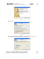
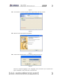
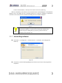
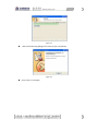
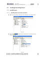
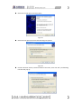
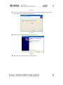
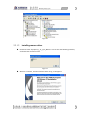
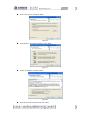
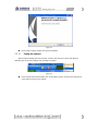
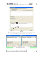
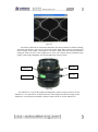
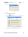
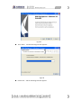
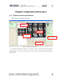
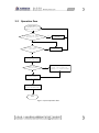
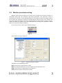
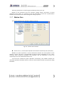
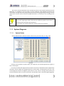
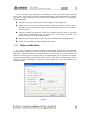
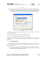
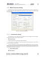
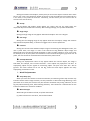
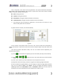
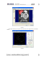
Owner's Manual MACHINE VISION SYSTEM Copyright Statement GD Han’s Yueming Laser Technology co.,Ltd. All rights reserved. GD Han’s Yueming Laser Technology co.,Ltd (Han’s Yueming Laser hereafter) reserves the right to modify the products and product specifications described in this manual without advance notice. Han’s Yueming Laser is not responsible to any direct, indirect, or consequential damage or liability caused by improper use of this manual or the product. Han’s Yueming Laser owns the patent, copyright or any other intellectual property right of this product and the related software. No one shall duplicate, reproduce, process or use this product and its parts, unless authorized by Han’s Yueming Laser . All the name refered in this manual only for identification, if belongs to other company’s registered trademark or copyright, proprietary rights of the name belongs to their respective holder. -1- Foreword Thanks for purchasing the laser engraving machine control system of our company. Before operating, please read this manual carefully to ensure proper operation. Please keep the manual properly for reference. Since the configs are different, certain models do not have the functions listed in this manual. Please refer to the specific functions for details. Due to the constantly tech update, the specification for reference only, subject to the real standard. Tags in this book: Special Attention: User must follow and perform as the manual. Otherwise, it could lead to errors or relatively serious problem. Alarm Note: User should comply with the attention and suggestion in this manual. it could bring much easier operation. Note -2- Contents Chapter 1 Introduction.............................................................................................................. 1 1.1 Working principle ...................................................................................................... 1 1.2 Software function description................................................................................... 1 Chapter 2 Installation ................................................................................................................ 2 2.1 Installing/Uninstalling Software ................................................................................ 2 2.1.1 Installing Software..................................................................................................... 2 2.1.1.1 Requirement ........................................................................................................ 2 2.1.1.2 Steps ..................................................................................................................... 2 2.1.2 Uninstalling Software ................................................................................................ 5 2.2 Installing/Uninstalling Drivers ................................................................................... 7 2.2.1 Install Drivers............................................................................................................. 7 2.2.1.1 Installing driver for motion controller ................................................................. 7 2.2.1.2 Installing camera driver...................................................................................... 10 2.2.1.3 Config the camera .............................................................................................. 14 2.2.2 Uninstall Drivers ...................................................................................................... 19 2.2.2.1 Uninstalling driver for motion controller ........................................................... 19 2.2.2.2 Uninstalling drive for camera ............................................................................. 20 Chapter 3 Operation instructions ........................................................................................... 23 3.1 System interface introduction................................................................................. 23 3.2 Operation flow ........................................................................................................ 25 3.3 Machine parameter setting..................................................................................... 26 3.3.1 Technics Para........................................................................................................... 27 3.3.2 Working Para ........................................................................................................... 29 3.3.3 Special Machine Para .............................................................................................. 30 3.3.4 Manual Para ............................................................................................................ 31 3.3.5 Set System Para ....................................................................................................... 32 3.3.6 Laser Para ................................................................................................................ 34 -1- 3.3.7 Motion Para............................................................................................................. 36 3.3.8 Backlash table ......................................................................................................... 37 3.3.9 System Diagnose ..................................................................................................... 38 3.3.9.1 System Status ..................................................................................................... 38 3.3.9.2 I/0 status ............................................................................................................ 39 3.4 Vision parameter setting ......................................................................................... 40 3.4.1 Camera parameter .................................................................................................. 40 3.4.2 Camera calibration .................................................................................................. 41 3.4.2.1 Grid calibration .................................................................................................. 42 3.4.2.2 Dot calibration ................................................................................................... 43 3.5 Create model and parameter setting ...................................................................... 45 3.5.1 Create model ........................................................................................................... 45 3.5.2 Model Parameter Setting ........................................................................................ 49 3.5.2.1 Find Parameter Setting ...................................................................................... 49 3.5.2.2 Model Parameter Setting ................................................................................... 53 3.5.2.3 Process Parameter Setting ................................................................................. 56 3.5.3 Model List Management ......................................................................................... 58 3.5.4 Joint BMP Function ................................................................................................. 59 3.5.5 Find Test Function ................................................................................................... 60 3.6 Layer Parameters .................................................................................................... 61 3.7 Control Panel ........................................................................................................... 63 3.8 Find Process Automatically ..................................................................................... 64 Chapter 4 Example .................................................................................................................. 65 4.1 Brand Transfer Cut Automatically ........................................................................... 65 4.2 Touch Screen Cut .................................................................................................... 71 Chapter 5 Fault Diagnose ........................................................................................................ 75 5.1 Common Fault Type of Vision ................................................................................. 75 5.1.1 The cut graph shifts to left/ right ............................................................................ 75 5.1.2 The cut graph shifts to the top/bottom .................................................................. 76 5.1.3 The cut graph deflects deasil/anticlockwise ........................................................... 77 -2- 5.1.4 Outside enlarge/inside shrink along X direction ..................................................... 78 5.1.5 Outside enlarge/inside shrink along Y direction ..................................................... 79 5.1.6 The position or angle of cut graph is wrong............................................................ 80 5.1.7 The size of cut graph is wrong ................................................................................. 81 5.1.8 The reverse and positive direction are not accord ................................................. 81 5.2 How to Improve the Speed and Precision of Vision Orientation ............................ 84 Chapter 6 Appendix................................................................................................................. 86 6.1 I/O port description................................................................................................. 86 Post ......................................................................................................................................... 87 -3- Chapter 1 Introduction This control system is suitable for vision cutting and developed basing on SmartCarve4.2 software platform. The system adopts mature domestic machine vision and motion control program, which is capable of image recognition, model matching and positioning, image contour extraction, automatic search and processing control. 1.1 Working principle The machine vision system is an automatic control system that searches, positions, and processes graphs automatically through intelligent camera. Grab images with industrial camera; Indicate the searching object of the vision system by making model; Drawing or import the cutting graph on the model image; Complete the automatic processing; 1.2 Software function description For the different technics, the machine vision system now supports search model cutting and search mark point cutting. The following three functions are available: Machine vision The machine vision includes data collection, vision display, correction, calibration, model extraction, search positioning, etc.; Motion control Motion control includes jog, laser burst, home, border cutting, automatic process control, state monitoring, etc.; Plot This software integrates simple graphics function, including the drawing of line, circle (arc), rectangular, polygon, Bezier curve, text, etc. It also can import vector or bitmap graphics, such as plt, dxf, ai, dst, bmp, jpg, etc. You can typeset and zoom in/out the graphs, promoting the graph preparation (contour extraction). For more information about this software, please reference the user manual of SmartCarve4.2 software. 1 Chapter 2 Installation 2.1 Installing/Uninstalling Software 2.1.1 Installing Software 2.1.1.1 Requirement Operating system: Windows2000/XP/VISTA/Win7 Computer: CPU: > 1GHz; Memory: > 1GB; 2.1.1.2 Steps Open the soft directory in the CD (or hard drive), find the SmartCarveInstall4.2.X.exe and double click it, and then the following dialogue box will show up: Fig. 2-1 Fig. 2-2 Choose your language and click “OK”. The system enters the following interface: 2 Fig. 2-3 Click “Next”: Fig. 2-4 Please read the software license agreement. If you want to continue, please select “I accept the terms in the license agreement”, and click “Next”: 3 Fig. 2-5 Click “Browse” to locate the path of the target folder, and click “Install”: Fig. 2-6 Wait for the final prompt for completion: Fig. 2-7 If select “Run SmartCarve4.2”, the following dialog box pops up: Fig. 2-8 Select the required language in the “Language” item, and select your required card type in “Machine”. Then, click “OK” to start the soft. 4 If select “Show Readme”, it will open the readme.txt for the update log. After the installation, two shortcut icon of SmartCarve4.2 will be displayed on the Windows desktop. Users can double click the “SmartCarve42”icon for execution. Softdog is required for execution. Users need insert the SmartCarve Softdog into the computer USB port. Fig. 2-9 Note If users no softdog, “SmartCarve42_Demo” will available for 10 days. Reinstall the software or system cannot extend the probation day. Please keep your softdog well, if you lose it, please contact our company to buy another one. 2.1.2 Uninstalling Software Click “Start”-> “All Programs”-> “SmartCarve4.2”-> “Uninstall”, and a dialogue box shows up: Fig.2-10 Click “Next”, and the following dialogue box will show up as soon as the progress bar completes: 5 Fig.2-11 Wait till the following dialogue box shows up upon completion: Fig.2-12 Click “Finish” to complete. 6 2.2 Installing/Uninstalling Drivers 2.2.1 Install Drivers 2.2.1.1 Installing driver for motion controller Right click “My Computer”, and select “Device Manager”, as in the figure below: Fig.2-13 Right click shown in Fig. 2-14: and Select option “Update Driver…” to have the interface Fig.2-14 7 Select the second option and click “Next”: Fig.2-15 Select the first option and select the following two options: Fig.2-16 Click the “Browse” button, locate the folder of the driver, then click “OK” ,the following interface will pop up: 8 Fig.2-17 It is seen from the figure above that the wizard is installing the driver. Please wait. In the process, the following interface will pop up: Fig.2-18 Finished the installation, you may need click “Finish”: Fig.2-19 After that, the “Device Manager” interface follows: 9 Fig.2-20 2.2.1.2 Installing camera driver Double click the “flycapture_1_8_3_23_x86.exe” icon to have the following interface, and follow the wizard to install: Fig.2-21 Wait for a moment, and the interface shown in Fig. 2-23 appears: 10 Fig.2-22 Click “NEXT”: Fig.2-23 Select the first option “I accept the license agreement” and click “Next”: Fig.2-24 Click “Next”: Fig.2-25 11 Select “Only for me” and click “Next”: Fig.2-26 Click “Browse” can choose install list. Click “Next”: Fig.2-27 Choose “Complete” and click “Next”: Fig.2-28 Select the first three options and click “Next”: 12 Fig.2-29 Wait the process bar running, then: Fig.2-30 Do not select any checkbox, click “Next”: 13 Fig.2-31 2.2.1.3 Click “Finish” button to finish this driver installation. Config the camera After finished installing the camera driver, initialize the camera’s scheme that base on different type of the camera.Open the procedure as follow: Fig.2-32 Click “Utilities→driverControlGUI.exe” as the above picture. And then the interface of camera driver comes out as follow: 14 1 2 Fig.2-33 Click “FlyCap.exe” in figure 2-32, they are the scheme and test software of camera, user can use them to test the connection of camera whether right or not. Left is CMC6050V, right is SM960 15 Fig.2-34 The interface will show the type of connected camera and serial, resolution, color, and so on. As the above picture shows two types (CMC6050V and SM960)of machine’s camera our company. The blank list of camera means that it is unconnected. You should check the connected line of the camera and whether the data colletion card is installed. Click the “Configure Selected” button, enter the parameters setting interface. Left is CMC6050V, right is SM960 Fig.2-35 In Fig. 2-35, you need to select two parameters: One is the “Format”, and the other is “Frame Rate”, you need select the right parameters for the camera .Left figure is the parameters of CMC6050V(the Format is 640×Y8,the Frame Rate is 30Hz) right figure is the parameters of SM960 (the Format is 1280×Y8,the Frame Rate is 30Hz) 16 Fig.2-36 In the interface shown in Fig. 2-36, you can set the brightness, exposure, gain and other parameters of the camera, and then click the “Save“ button to save the modification. The ray from the exterior surroundings and the object’s color are difference lead the lighteness differently. you need adjust the parameters base on the factual instance. Note The neutral parameters of the camera can be adjusted through the vision module’s camera parameters of Smart Carve4.2 directly. When the above steps are finished, click the “OK” button in the interface shown in Fig. 2-37 to enter the interface below, and view the captured images in real time: 17 Fig.2-37 The picture shows not as usual means that there are some problems in camera installing and driver parameters. User need to check and install again about camera connected and driver scheme. If the image is too bright or too dark, it means that the neutral parameters setting of camera is error. If the image’s size is error, User need to set the resolution ratio rightly. If the image is illegibility, user should adjust the camera’s focus. Screw 1 Aperture 1 Screw 2 Aperture 2 Fig.2-38 Use “Aperture 1” in Fig. 2-38 to adjust the brightness, and then rotate “Screw 1” to lock “Aperture 1”; use “Aperture 2” to adjust the focus; if the images resolution isn’t high, rotate “Aperture 2” to improve the resolution, and then rotate “Screw 2” to lock “Aperture 2”. 18 2.2.2 Uninstall Drivers 2.2.2.1 Uninstalling driver for motion controller Right click “My computer” and select “Device manager” to pop up the following interface: Fig.2-39 ,and the interface below shows up: Right click Fig.2-40 19 Choose “Uninstall” and the following interface appears: Fig.2-41 2.2.2.2 Click”OK”. Uninstalling drive for camera Double click“ 2-42 ” icon to have the interface shown in Fig. Fig.2-42 Choose “Remove”,click “Next”, and the following interface appears: 20 Fig.2-43 Click “Next”,and the following interface appears: Fig.2-44 Please wait,and the following interface appears: 21 Fig.2-45 Click “Finish” to complete the uninstallation. 22 Chapter 3 Operation instructions 3.1 System interface introduction Software main interface shows as follow: Drawing bar Vision area Drawing area Layer parameter Control panel Fig.3-1 software main interface This software included plot module, vision module, motion control module and parameters setting module. For more information, please read “Han's Yueming Software Manual for Smartcarve42” 23 Model list area Image shown area Operation and para setting area Fig.3-2 vision model main interface Vision model included display section, module list, operation and parameters setting. Image display section mostly used to collect and display vision image, it can be taken model directly and show the image at the same time when working. Module list shows currently machining module, right click and set the parameters as you want. Operation and parameters setting section mostly used to operate the vision model. 24 3.2 Operation flow Start Smart carve42(machine type is machine vision system) Hardware(controller and camera) Initialize in gear? Exclude Hardware problem No Yes Whether the calibration file exist Vision calibrating No Yes Create or load model(or model base) Whether setting process file No Drawing or loading process figure, save as smc file, binding it to opposite model Yes Setting vision research parameter and process parameter Press “Start” to process automatically Finish Fig.3-3 system operation flow 25 3.3 Machine parameter setting Machine Vision System use the No.4 controller of our company for the main controller. Its parameters divide into user parameter and factory parameter. User parameter relate on machining arts and crafts, it is the add supplement for the image parameter.This chapter involves the machine tool parameter settings of Yueming Machine Vision System. The machine tool parameters affect the working state of the engraving machine. Please read this chapter carefully, and do not modify any option if you haven’t understood the meaning of the parameters. Please back up the parameters before modifying. In main menu “Tools”, select option “Machine Setting”: Fig.3-4 The interface as in Fig. 3-5 pops up: Fig.3-5 machine parameter interface The button for the following function: Apply: Save the currently parameter setting Import: To keep the format file ini to your system interface parameter sets Export: The system for keeping papers in the format ini Cancel: Exit Parameters of the system interface 26 User parameters include arts and crafts parameter, machining parameter, special machine parameter and manual parameter. Factory parameters include system parameter, laser parameter, movement parameter and reflect clearance. Now explains as follow: 3.3.1 Technics Para Motion Para: Start Vel: The step motor requires setting the start frequency, i.e. this parameter (unit: m/min). Jump Vel: It is the speed in idle motion section in the course of processing. To improve the processing efficiency, please set it to a larger value (unit: m/min). Jump Acc: It is the acceleration in idle motion section in the course of processing. To improve the processing efficiency, please set it to a larger value (unit: mm/s2). Jump Delay: The device runs in high speed in idle process. To avoid the trembling during continual cutting, please set this parameter. Vel Ratio: Set the parameter of velocity ratio, which affects all the speeds of the system; Power Ratio: Set the processing power ratio, which affects the processing power output of all processing; Corner Ratio: Set the corner power ratio of processing, which affects the corner power output of all processing; Backlash adjust An adjustment process for the scanning of the reverse of x games, (unit: mm) Engrave parameters: Engrave mode: Two options are available: Black or White, the effect as follow: Engrave Black Engrave White 27 Fig.3-6 Engrave Ratio: The pulse amount corresponding to distance of 1 mm (unit:0.01% ~100%) ratio = 2 ratio = 0.2 Fig.3-7 Cut Para: Corner: precision and velocity settings are available on both sides of the sliding block. If the sliding block is on the right, the speed at the corner is higher but the precision is lower, while the cut corner is smoother; if it is on the left, the speed is lower but the precision is higher, while the cut corner is sharper. Precision corner, low speed Smooth corner, high speed Fig.3-8 Small Circ: It is necessary to reduce the speed to cut small circle. You can drag the sliding block to select the speed. The smaller this value is, the lower the small circle processing speed is. SetPos Para: It is the processing anchor, which is also called processing reference point and equivalent to the work piece origin. This is a fixed value relative to the mechanical origin. SetPos X: This parameter is used to set the position relative to the X direction of the origin (unit: mm). SetPos Y: This parameter is used to set the position relative to the Y direction of the origin (unit: mm). 28 3.3.2 Working Para The Working parameters dialog as follow: Fig.3-9 Cyc Number: set the number of cut files (1~9999) Total Number: The cumulated processed work pieces of the system Start Position: Set the start point of processing,CurPt: start processing from current point; Set Pt: start processing from locating point Transfer Machine Parameters Feed par Row: Set whether enable progressive feeding: No – disable progressive feeding; Yes: enable progressive feeding; Feed Vel: The speed of feeding (unit :mm/s Range:0~9999.99) Compensation: The length compensation of the entire feeding (unit:mm) Manual Adjust: When the feeding axis has deviation, make the feeding in accurate state through manual alignment. Feed at last: Processing is complete if you have sent for Array parameters Rows: he processing number of work pieces every row in array processing(Range: 1-9999) Columns: the processing number of work pieces every column in array processing (1-9999); Row Distance: the row misalignment of work pieces in array processing (unit: mm, -999.99 – 999.99); 29 Col Distance: the column spacing of work pieces in array processing (unit: mm, -999.99 – 999.99); Row Indnt: the Row misalignment of work pieces in array processing (unit: mm, -999.99 – 999.99); Col Indnt: the column misalignment of work pieces in array processing (unit: mm, -999.99 – 999.99); Row Mirror: Used for models with intelliPCInt dual laser heads and the even rows process the graphs in X /Ydirection mirror imaPCI (0: No; 1: Yes); Col Mirror: Used for models with intelliPCInt dual laser heads and the even cols process the graphs in X direction mirror imaPCI (0: No; 1: Yes); 3.3.3 Special Machine Para The setting interface of Special Machine Para is shown as follow: Fig.3-10 Rotate Axis Parameters(for Machine CMA6040K/1390K) Rotation dia. (mm): To set the diameter length for the rotation axis. Pulses per rev: To set the pulse number required for every revolution. Air curtain para (For CMA1625): This parameter use to set the switch position of control air curtain switch. 30 Position of Switch 1 (mm): To switch on the air curtain when the laser head arrives at the position. Position of Switch 2 (mm): To switch on the air curtain when the laser head arrives at the position. Pen para (CMA1610F-P/1810F-P): Pen offset X (mm): departure distance from X to the pen. Pen offset Y (mm): departure distance from Y to the pen. Vision Transfer Parameters (for SM960F/CMA1610TF-V): Transfer Dis(mm):set the parameter about transfer distance,unit :mm. Transfer Axis:choose which axis will transfer. 3.3.4 Manual Para The setting interface of Manual is shown as follow: Fig.3-11 Jog Vel: The feeding speed (unit: mm/s, 0-9999.99) when the motion axis feeding is controlled in manual mode; Jog Acc: The feeding acceleration (unit: mm/s2, 0-9999.99) when the motion axis feeding is controlled in manual mode; Shot Power: The laser energy while spotting (the actual output energy is the sum of this value and the minimum energy) (1-32767); Shot Time: The laser output time while spotting (unit: ms, 0-99999); Jog Mode: The manual control mode: 0-continuous motion; 1-inching motion; 31 Step Distance: The inching feeding when the manual control mode is inching (unit: mm, 0.01-999.99); Scale Margin: The deviation (margin) of the actual frame from the graph frame while testing or trimming; Scale Mode: Available in array processing: 0-cut LARPCI; 1-cut SMALL; 3.3.5 Set System Para The setting interface of System is shown as follow: Fig.3-12 Home Para Fig.3-13 Home Style: Four home modes are available: limit, home, limit +Index signal home and Home +Index home, as in Fig. 3-14. Fig.3-14 Home mode 32 Home Dir: Two home directions available: positive and negative. Home Vel: Set the home speed of every axis respectively (unit: mm/s). Offset: It is the distance that the machine (laser head) drifts relative to the origin switch to avoid the device staying in the origin signal triggering state after collecting the origin signal (mm). If it is positive, the machine moves certain distance to the reverse direction of home; if it is negative, the machine continues to move to the home direction for certain distance. Generally, this value is positive. Note In Home + Index (or Lmt + Index) mode, install the Home switch between two adjacent Index signals. When Home (Lmt) switch and Index signal superpose, it may cause collection error of Index signals. Han’s Yueming has set the machine before delivery. Please modify the parameters under the guidance of qualified personnel. Sensor Para: Fig.3-15 Limit switch config Corresponding card has been connected Limit signal and select the relevant options Other Para: Start Auto: The operation performed when the device is started. Three options are available: NONE, Go Home and Go Setpos. Machine type: Two feeding model and standard model are available Language: Set the langua of this system: Chinese or English; Open Cover Protect: Two modes are available: Available and invalidate. Control mode: 33 Three modes are available: Analog, pulse + dir and +/- pulse, as in the figure below. Please select the motor control mode according to the actual condition of the device (note: blue box controller doesn’t have analog control mode) Fig.3-16 3.3.6 Laser Para The setting interface of laser is shown as follow: Fig.3-17 Laser Parameters dialog The setting of laser parameters follows: Laser Num Two options are available: 1 indicates that only up laser is single laser head processing; 2 indicates that two channels of laser are double laser head processing. Adjust Mode: When double laser head, set the adjust manner of double laser head, manual or automatic Min. Dis (mm) : When double laser head, set the minimum distance between these two laser head Power mode: Three options are available, as in Fig. 3-18 34 Fig.3-18 A. In duty cycle output mode, the controller outputs pulse quantity to control the laser, and adjusts the laser energy by changing the duty cycle of the pulse. In this mode, you need to set the frequency of PWM. The maximum output frequency of the system can’t exceed the maximum frequency of the laser. Fig.3-19 B. In frequency output mode, the controller outputs pulse quantity to control the laser, and adjusts the laser energy by changing the pulse frequency. Fig.3-20 C. In analog quantity output mode, the controller outputs analog quantity to control the laser, and adjusts the laser energy by changing the analog quantity. In this mode, it is necessary to set the pre-voltage and maximum voltage of the laser control power supply, where pre-voltage is the minimum voltage of the energy output port when the laser is idle. Fig.3-21 Power Ctrl Mode: Two energy control modes are available: Linear servo and constant value output, as in Fig.3-22. Fig.3-22 Laser On/Off Delay: 35 These two parameters are used for light on/off delay of laser (unit: μs). Because of the hysteresis from the controller sending motion instructions to actual movement of the motor, it is necessary to set this parameter to ensure the synchronization between laser and the motor motion during laser cutting in process. 3.3.7 Motion Para The setting interface of Con X/Y/Z/A is shown in Fig.3-23: Fig.3-23 Motion Para interface Set the Con X, Y, Z and A pulse equivalent of the device respectively (unit: pulse/mm). Whether the pulse equivalent is correct determines whether the actual position of the motion is correct. The user is recommended to keep the pulse equivalents of con X and Y consistent while mechanical designing. This parameter sets the equivalent of every axis respectively to trim the mechanical motion error. To let the user calculate the pulse equivalent conveniently, this software provides the automatic equivalent calculation function. Click the “Auto Calculate” button to pop up the dialog box below 36 Fig.3-24 The procedure follows: (1) The user selects the axis to calculate the pulse equivalent first, and enter the set motion length L (default: 100mm); (2) Move the selected axis for L distance through “Inching” function in lower computer; (3) Measure the actual inching distance L of the axis with a rule, and enter this value into the edit box of actual motion length; (4) Click the “OK” button and the software calculates the pulse equivalent of current axis. Soft Limit X/Y/Z and A (range :0~9999.99, unit: mm) Set the mechanical stroke, which is equivalent to soft limit function. 3.3.8 Backlash table Function: Set the reverse clearance during cutting processing, which is shown in Fig. 3-25 below: Fig.3-25 37 The reverse clearance depends on the mechanical precision and response speed of the laser. Generally, it is possible to set one group of reverse clearance value (default: 0) because the speed doesn’t change obviously during cutting processing. During engraving processing, since the speed value and the reverse clearance change obviously, it is necessary to set according to the table. Note The factory parameters and equipment hardware parameters affect the working state of the engraving machine. Please do not modify any option if you haven’t understood the meaning of the parameters. If you modify your factory parameters, please restart your computer. 3.3.9 System Diagnose 3.3.9.1 System Status System state function: check the motion state of every axis and track, as in Fig. 3-26: Fig.3-26 Under the stir interface of system status, if the signal on, the relevant light will turn green, if not, it may be gray. Four ways of shaft state signal shows the state of the four manipulators which supported by controllers. Not all models are equipped with four control shafts, it all depends by use case. User can through the interface to diagnose system when it error. Such as: Through this interface you can check whether there is a motor drive alarm, also whether there is axial limit signal triggering. 38 Motion status mainly show format motion status. If the equipment errors, this interface can help you diagnose the system rapidly. 3.3.9.2 I/0 status Function description: check whether the connection of every I/O port is normal, as in Fig.3-27: Fig.3-27 I/O include EXI, EXO and Special Input . EXI use to connecting the simple import sigle, such as the sensor of water sensor and cover protection.The define about the neutral EXI of our company’s No.4 controller as follow: EXI0 ——water sensor sigle, this light light means normal,if not ,water sensor will trigger and the laser cannot work. EXI1 ——cover protection sigle, this light light means cover, at the machine which set the cover protection effectively, wporking stop. EXI2 ——The second water sensor sigle, it means the second laser’s water sensor’ status at the machine with two laser EXI3 ——Stop sigle, this sigle keeping light under the normal condition. When you press this button, this sigle will not light. EXO use to connecting the simple output sigle, such as the three-color light, alarm machine. Click the sigle light to control the output status directly. The output light lights ,the sigle will out from the relevant output. The define about the neutral EXO of our company’s No.4 controller as follow: EXO0 ——use to change spin sigle, this sigle lights mean t it change to the spin sigle. EXO4/5/6 ——use to control the three-color light. EXO7 ——alarm machine control 39 Attention: The define is not for all No.4 controller effectively, please read the equipment’s electrical manual about the pratical setting. Special input is managed by controller, include limitted sigle, home sigle and laser switch sigle. Different equipment has different sigle switch . 3.4 Vision parameter setting Vision parameter include demarcate and camera setting. Click “parameter setting” and enter vision parameter setting interface at vision main interface. Fig.3-28 3.4.1 Camera parameter Camera parameter mainly use to setting the parameter which relative with the equipment’s camera. Including the type of camera, install parameter, use parameter, and so on. Camera type: Choose PGR130 if the machine is SM960, Choose PRG30 if the machine is CMC6050V. The system will awake you to restart after change the type of camera. Camera install parameter: There is excursing position between shoot area and laser’s position. In order to incise rightly, you need to set the offset. Cam offset X(mm): The offset between lens center and X direction of laser head Cam offset Y(mm): The offset between lens center and Y direction of laser head Camera parameter: 40 It use to setting collect image Due to the difference of the ray outside and the working object’s color, it will make the camera’s imaging effect different. These parameters use to adjust the effect of image collecting. But if the system hasn’t detected the camera, the parameters cannot be adjusted. Gain (dB): setting the camera’s gain, the gain bigger, the more brightness. Shutter (ms): the time of the camera to take a picture, the shutter’s range is relative with the frame rate of camera. In order to ensure collecting image in time, it should not be set too large. Sharpness: setting this parameter to adjust the image’s sharpness, base on the detail and character of different image, the sharpness is not the larger the better, this parameter mainly use to adjust model’s detail. Gamma: this parameter work in setting sharpness to affect the final imaging purpose. Frame rate: the degree of refurbish image every second. 3.4.2 Camera calibration The use of calibration is revise the original collected image, and count the corresponding relation between image’s pixels and actual distance automatically. Because the camera lens may distortion, it must be revised to create calibrating file at the first time. If the vision install or the thickness of material does not change clearly, the calibrating file can be fixedness. The system will load the calibrating file automatically when it starts. If you want to calibrate again, please delete the primary calibrating file which the system loading and restart the software. The interface follows: Fig.3-29 41 Attention Before you calibrate , you must make sure the equipment’s motion (X/Y axis pulse) setting rightly, X axis and Y axis plumb each other, it isn’t twitter when it move straight, if not, it will affect the result of calibration, make the final working error bigger. Try your best to make the platform keep horizontal, if not, the working error will be made bigger. This system support grid calibration and dot calibration. The two manners’ step as follow: 3.4.2.1 Grid calibration Prepare a sheet of A4 paper, put it under the laser on the working platform, keeping the paper clean and do not penetrate it. Move the laser to the left down of the paper, set shooting laser’s energy and manual speed. Make the laser’s work show on the paper distinctly (but do not lacerate the paper). Enter the calibration interface, choose “grid” at “calibration type”, set the row distance and coloum distance to 10mm. Click “Draw Cross” the equipment will control the laser working which on the paper automatically. The camera will place above the cross after finished drawing. Please attention: if found that the paper is not suitable and must stop motion at the working progress. Please press the “stop” button on the control plate. If you found the sight extension haven’t been bespreaded by gridding after finishing the above steps, please adjust the camera’s position through the control plate. If you can’t see the gridding clearly in the sight extension, maybe it too light or too dark, you may adjust the brightness through camera’s parameter to make sure that you can see the gridding clearly through the vision display area. You must make sure the paper’s position hasn’t changed in the whole process. It is need to remove if there is something keeps out, such as laser head and air tube. 42 Fig.3-30 Click the “Calibrate” button; the system calibrates and calculates automatically; wait for a moment; if the calibration is successfully, the “Save as” dialog box pops up, and you can click the Save button to save the data. If the calibration fails, the corresponding error dialog box also pops up. It need to check the calibrate steps and calibrate again. Fig.3-31 After calibrating, the system displays the storage path and calibration result of current file in the “Calibration file” text box: Col result X (mm/pixel): the length of every pixel in X direction, Col result Y (mm/pixel): the length of every pixel in Y direction Start the system next time, it will insert the calibration file automatically, users do not need to calibrate again. The result of calibration is very important, wrong calibration may lead the vision and size error. 3.4.2.2 Dot calibration DOT calibration doesn’t need to draw the gridding, but need to use the DOT calibration which our company equipped. Different type of machine use different calibration. The manner of DOT calibration follows: Put a sheet of blank paper on the processing platform; put the transparent calibration with black dot on the paper. Keep the calibration stay horizontal, adjust the camera parameter, make the image can be seen clearly. 43 Fig.3-32 Dot calibration Enter the calibrate interface, choose “dot calibration” in the “calibration type”, Fig.3-33 In above interface, “Row Distance” and “Coloum Distance” indicate the space between two points on the plate. Enter according to actual values (the machine SM960 is usually 10mm and the machine CMC6050-V is usually 0.5mm), and then click the “Calibrate” button; the system calibrates and calculates automatically; wait for a moment; if the calibration is successfully, the “Save as” dialog box pops up, and you can click the Save button to save the dat. If the calibration fails, the corresponding error dialog box also pops up. Above steps gained the result of calibration, but it also need to count the calibrating angle, follows: 1) Put a sheet of blank paper under the laser, move the laser to the middle of the paper through the controller. Set the laser’s energy and manual speed, make the laser cross to be seen clearly,( but do not penetrate the paper) 44 2) Click “draw cross” on the dot calibrating interface, the equipment will control the laser to draw a “cross line”. 3) Move the laser, let the above cross and the center of the green cross in the vision show area superpose,( if the image too light or too dark ,it will be seen unclearly, then you can adjust the lighteness through the camera parameter) 4) Look into the two cross, whether they are superposition it need to set the deflexed angle. If it doesn’t superpose: enter the dot calibrating interface, set the deflexed angle, click “refurbish” button, look into the change of image shows area. User should repeat to set and refurbish the angle again and again, ensure the two cross complete superpose. At last, click “apply” to save the calibrating parameter. For SM960, we suggest the user choose the gridding to calibrating, this manner is not only convenience but also little account and it just cost a little. Note For CMC6050V, you can just use the dot calibration. 3.5 Create model and parameter setting Model is used to the reference standard of vision researching. Whether the model facture is good or not that decide the lookup orientation’s result is right or wrong and speediness. 3.5.1 Create model Ensure the system parameters and vision parameters have adjusted normally before you set up the module. The wrong value or calibrating result will make the module’s pick up the distorted image, and lead the module making differ from the fact. The process follows: First, put the working object under the vidicon at the watching pattern. Click “stetting model” button, vision area will stop collecting image. At the same time, A blue rectangular box will pop up at the screen as follow: 45 Model selected box Fig.3-34 Click the model select box; it will be navy blue when it has been selected. In this interface, click the four angle of the module selected box, you can pull and extend it, drag its four lines and move the module selected box. Then, you can move the model selected box to the place of module setting what you need. 46 Fig.3-35 After setting the selected area of the model, click the “set up module” button, in the interface, the “save as” dialog box will pop up. Fig.3-36 Select the location and file name, and click Save. The model file will be saved in .mdl format. The created module will appear at the module list as follow: 47 Fig.3-37 Finished to set a model as above, click “save module base” button to save the current model list. The software will load the current model automatically next time. If the users need to set up more models, please repeat the above steps. It will pop up an operation menu of vision interface when you right click in the main interface; it is convenience for the user look into detail and operates as follow: Pointer: move the module selected box, ext. Pan: moving image, Zoom In: enlarge, Zoom Out: shrink, Fit Image: appropriate size Zoom 100﹪: Show factual size. Fig.3-38 Note Module selecting is not the bigger the better, the selected figure has enough visible character is ok. The bigger of the image selecting, the looking time will longer, but if the module selecting is too small, the orientation’s precision will not enough. 48 3.5.2 Model Parameter Setting Model parameter includes find parameter, module parameter and vector file. Right click on the model image, the model operating menu will pop up, select” setting” to enter the config model parameter. Fig.3-39 config model parameter 3.5.2.1 Find Parameter Setting The system base on the model which setting by user to find working. The find parameter interface shows in figure 3-39, the explain follows: Vision find type: Setting the find type. It includes find model and find dot. In the manner of find model, the system will find the similar image base on the current model, orientating and machining it. In manner of find dot, the system will find the similar signed dot base on the current model, and account the central position of the signed dot automatically. Then ensure the position of the working image that base on the position of multi dot to complete working. Presently, you can only choose the “area find” to working. Vision find parameter Want number 49 Setting the amount of find object, namely that you can see the object’s amount at the same time in your vision. This parameter should not be set so large that affect the find speed. But if it is too small, it may make the find lose. Commonly, set the entries you can see one time at current vision area in theory. Accept The find object and model’s similar degree, the range is 0.5~1.0, the range larger, the requested object and model more similarly. But if setting too large, it may make the find lose. Angle range Setting the angle range of may appear about the find object. The unit is degree. Size range Setting the size changing range of may appear about the find object, change this measure may lead the find speed slowly, so we do not suggest user to set this parameter. Contrast Setting the contrast value between object image of researching and background color, the unit is pixels value, the range is 1~255. If the contrast too big between object image and background color, this value should be set bigger in order to reduce interfere, if not, set it small. For example, if set 10, the system will research it in the area which the figure’s gray value over 10 pixels, the area cannot be researched and orientated if the pixels less 10. Overlap threshold Setting the superposition value of may appear about the research object, the range is 0.01~0.99, For example, set 0.3 means that 30﹪ of the object may superpose. Low 30﹪ of superposing object may be signed to researching object. The part more than 30﹪ will be ignored. This value should not be set too big, avoid the same object appears too many superposing orientation’s result. Work find parameter Jump delay (ms) When you move the camera to research orientation, the dithering of the stop moment may lead the camera collect image unclearly. Set this parameter to deal with image dithering. If this parameter set to small, the research may lose and the orientation may wrong. Whereas, set too big may add researching time, affect working efficiency. User should set it rational base on the instance of factual use. Parameter is 200ms. Work find type Work find type includes area find, array find and manual. (1) When choose the “area find” ,the interface follows 50 Fig.3-40 In the area find, users need to set vision size of camera and area size of working object. The system will account researching path automatically base on the user’s setting and take researching working in pointed area. This manner is equal to the instance which the image is too small and array too tight. Vision width (mm): setting current vision width of the camera Vision height (mm): setting current vision height of the camera Workspace X (mm): setting the width of the object area of which need to researching, please attention when you set, do not overstep the X axis’s path. Workspace Y (mm): setting the height of the object area of which need to researching, please attention when you set, do not overstep the Y axis’s path. Start position Setting the start position of the current find model, you can choose “current position” or “machine zero position” to count start position. When you choose “current position”, “start position X” and “start position Y” take the current position for the reference point to count start position. if they all be set zero, it will start orientation from current position. When you choose “machine zero position”, the system go back to machine origin firstly, “start position X” and “start position Y” are the equipment’s utter coordinates. (2) When choose “array find” the interface follows, Fig.3-41 51 In the “array find”, users need to set array parameter. The system will find the orientation object base on the array parameter. This manner is equal to be used in the instance of object image’s array that orderliness and tidiness. Rows: setting find rows Columns: setting find columns Row distance: setting the distance between row and row, Column distance: setting the distance between column and column, The meaning of the start position’s parameter is as the same as area find, so if you want to read, please refer to area find. (3) When choose “manual”, the interface follows, Fig.3-42 In the “manual”, find position take on list form. User need to import the coordinates by manual. This manner is equal to be used in the instance of object image’s array that ruleless and messy. The manual interface add demo model, user can use manual control expediently, the operation steps follows, (1) Press (2) Press image. to come back start position (if it has come back, this step can be omitted) 、 、 、 these four keys, the camera will move to the first above (3) Click “insert” button insert the coordinates of current position to the list. (4) Repeat the above two steps, continue to register the following image coordinates. For the list which has registered data, you can change its number through double click the form. You can operate “insert” and “delete”, and also arranging find position through “move up” button and “move down” button. “orientation” button use to move vision to the position of current selected form to test whether the number is right. 52 3.5.2.2 Model Parameter Setting System interior, model is described by a series of character. The character is good or not, determines the speed and veracity of object finding. The orientation effect or speed cannot attain user’s request, the model parameter need to be adjusted, the interface follows, Model reference point Fig.3-43 Granule: setting the granule of characteristic points, the more large you set, the less characteristic points, the sooner will the find, but the worse will the precision. Granule2: setting the second characteristic points, the granule cannot exceed the current one, the lower it is, the higher the precision. Noise: setting the noise, some disturbing point can be sieved when you augment noise. Threshold: setting the threshold, some disturbing point can be sieved when you augment threshold. Different model has different character, setting different model parameter to achieve best effect. The beginner should test again and again to pile up setting experience, Note Characteristic points are not the more the better, the more characteristic points, the slower find speed. More characteristic points are easy to bring disturbing, it will debase the find precision and lead find failing. The model characteristic points’ detail in figure looks richness, but 53 it is not good for find orientation of model. Overfull detail character form disturbed points, it is easy to lead find failure or too slow. Adjust properly to achieve best as follow Fig.3-44 The above operations reduce model characteristic points, only save the image’s primary character. For the figure that the model character can be reduced if it is not vivid enough. Or may make the orientation unfaithfully and lead incise disorderly. Model mask Model mask is mainly use to the occasion of image disturbed too much. Using this function can mask some disturbed image, and then take the characteristic points. Tick model mask and click the “model mask” button. The interface pops up as figure 3-45 Tool bar’s functions: open, save, save as, cut, copy, paste, redo, undo, erasure, mask offset and size settings, show shape control, select, choose, image move, zoom in, zoom out, fit image. The tool in the left: Dashed line, color fill, pen, brush, circle rectangle, white and red. Red means masking image, white means the part needs to save. 54 Fig.3-45 In the above interface, the red part is the masked area, click “apply” button, the interface follows, Fig.3-46 55 3.5.2.3 Process Parameter Setting After created model, need to set the corresponding working image of this model. System find object through model, working through working image. Working parameter only support our company’s .smc file. The manner follows, Created model (double click and open model in the model list), software drawing area will show the current vision image. The one signed red cross is the position of model image. Show as follow Fig.3-47 Choose the suited drawing tool to drawing incision line in the drawing tool bar (usually, draw profile, using bezer to drawing incision line is convenience.). Or, insert the image which draw by drawing software (such as, Corel Draw) through image insert and fit the position. The green curve in the below figure is the incision line image. 56 Fig.3-48 Setting the image working parameter (the working line is the green image as above, it need to set green image’s working parameter.) and save as “*.smc” file. (Save the above figure as “Test.smc “file to desktop.) right click the current model in the model list , the model menu will pop up, select “vector file”, enter vector file setting interface as follow, Fig.3-49 Click button in above figure, open file dialog box will pop up. Select the last saved smc.file, and then click “apply”, finishing the working file setting of current model. If you want to make over or reset the working image of former image, you can double click the model object the one you want to make over in the model list. It will load an smc file of this model automatically at the drawing area. Repeat the above steps, and then finish to making over and resetting. Note After you created model, the system will create a BMP bitmap file (such as, the created Test.mdl model will create a bitmap file named Test.bmp in the same list.) which the name is the same as the model in the list of saved model file. User can insert the bitmap to other image design software (such as, Corel Draw) to drawing the model working image. And then create the image’ format file (such as, plt, ai, dxf) which our company’s software supported. It is convenience for user to drawing. 57 3.5.3 Model List Management This software manage model by model base. One model base may include many different models. It offers a model list to express the current model base at the right side of the vision interface. It can be working by insert some model, setting and arrange the model in the list. Right click the model list, the operation menu will pop up as follow, Functions of the menu, Open: the same as double click model function. Open current model, setting the current model to an originate working model, it will be green. If current model has been set not working (it may be gray), open is useless. Config: enter model config interface. Set vector file path: enter the setting interface of model’s vector directly. Load model: load model to current list. Load and insert to current position: load model and insert it in front of the current model position. Delete: delete current model. Delete all: delete all models in the current model list. Process: set the current model process, model shows gray. 58 Process only this model: set the current model process, all of others in the list do not process. Process all: set the entire model in the list process. No process: set the current model not process, model shows puce. No process only this model: set the current model not process, all of others in the list process. No process all: set the entire model in the list not process. Move up: move the current model up to a position. Move down: move the current model down to a position. Move top: move the current model to the top of the model list. Move bottom: move the current model to the bottom of the model list. Besides, there are “load model library” and “save model library” in the function area of vision interface . Click “load model library” button, open file dialog box will pop up, select model library’s file (save as *.lib) . The current library will be covered if the new model library loading. Click “save model library” button, save file dialog box will pop up, save or save as the current model. Note System default will create a model library file (default.lib) at software install content. If users haven’t pointed the file name to save, the system will default to save current model in this model library and load automatically next time when you start software. 3.5.4 Joint BMP Function Generally, the vision range of our company’s brand cut equipment is 160mm×120mm. If the working objects overstep this range, camera cannot see the entire figure one time. Base on this instance, you can take “joint BMP” to working. Operation as follow 1) Create model, if the image overstep vision range, you can only take the part image with vivid character for model. After created model, keep the camera and object fixedly. Tick “joint BMP” in the vision interface as follow figure, 59 Fig.3-50 2) The functions of joint BMP can be used at this time; it is effective of “start” and “joint”. Click “start” button to start jointing. 3) Operate control panel, move camera and stop at the next area that need to joint. Click “joint” button to jointing image. You can see the model image has jointed automatically in the drawing area. 4) Repeat last step, till the whole object image jointed and show in software drawing area. Finished the above steps means finished jointing a large image. And then, user can drawing process image on this image. The manner is the same as 3.5.2.3. Note Attention Tick in the vision interface, you can double click to move camera through mouse at the image vision area. The green cross will move to the double click position automatically. Before you joint image, you must ensure motion(X/Y axis pulse) of equipment has set rightly. X axis and Y axis plumb each other, and the calibration is right. Or joint veracity will be affected. Finally, augment the error. 3.5.5 Find Test Function Whether the model can orientate object fast and rightly. You can find test it first. 1) Open the testing model (double click in the model list) ,setting pertinent parameters (model parameter and find parameter) and move camera to the position that need to test. 2) If the system is in RT pattern, click “stop RT” button, let the current image on stop situation. 3) Click “find orientation” button and wait a moment, the green pane will show in the object position of RT interface and mark current orientation result (pixel and deflexed angle) if it find successfully. It would change not if find failure. 60 Fig.3-51 4) If continue to test, click “RT pattern” to switch back RT pattern state. Move camera to next position and repeat the above steps. If the testing object is bitmap, not the current real-time RT, you can load image at stop RT pattern, and then find testing it. Note System use current model image for reference to find, it can’t be find if the object overstep vision range. As above image , it can only find the three middle object, three object cannot be find at up, down and right side. 3.6 Layer Parameters The layer parameters’ interface of No.4 controller in Smart Carve 4 as follow, layer parameters mainly use to set different color layer’s image working parameter. 61 Work power (%): Set the amount of laser energy during the processing. 100% means the most power. Such as the laser tube with 60W.set work power to 50%, means current process power is 30W. Corner power (%): Set the amount of laser energy. must smaller than work power. This parameter is inefficacy to cutting process. Layer list Layer Para small corner power big corner power Fig.3-52 Work Para Work vel (mm/s): the speed of cutting. Work acc: the larger the parameter is, the less time it accelerates to work vel. Note Please read “Smart Carve 4 software manual” about others parameter setting and usage of layer parameter: “ Hans YueMing Smart Carve4 software manual” Para Info Fig.3-53 Layer parameter 62 3.7 Control Panel The control panel completes the motion and processing control of the machine, including manual, home, laser and cut processing, etc. The main interface is shown in Fig. 3-54: Fig.3-54 Manual model: Press the Up/Down/Left/Right arrows to realize the feeding control in positive or negative directions of X and Y axis. The “HOME” key in the center is used to return to machine origin. The origin here is the mechanical origin and the home mode depends on the settings of system parameters. The key is used for the feeding control in positive and negative directions of Z axis in feeding system. It isn’t used in this system. Step: This parameter is used to switch the manual mode, including continuous and step. When this option is selected, the system moves in step mode. Every time when you press the feed button, the motor moves certain distance and the step displacement depends on the parameter later. The motion speed is set in “Vel” parameter. Laser model The laser module is mainly used to control laser shot. The laser shot power and time are set in “Laser power” and “Laser time” respectively. When set “laser time” to 0 means current laser continue. Cutting model Go scale: Enter the test (go scale) function. Cut edge: Enter cut scale function Start: Process the graph 63 Pause: Pause current processing Stop: Stop current processing Cut information and alarm information Cut time: account the time from start process to finish process or pause. Time reset: reset cut time to 00:00:00. Cut number: account machine current process number. Number reset : reset process number. Limit Alarm: Show the alarm information about limit. Axis Alarm: Show the alarm information about axis alarm. Water Alarm: Show the alarm information about water. Open Cover: Show the alarm information about open Cover. Emergency: Show the alarm information about emergency button. Cut information and alarm information are convenient for the user to observe the equipment’s working state. More system state, please refer to 3.3.9 Note 3.8 Find Process Automatically Base on different machine scheme and process technics, the manner of find process automatically is different. Process operation interface and pertinent parameter are also different. Main steps are the same as: take model→drawing image →set parameter →start process. Base on different machine scheme, ours equipment include common vision cut, feeding vision cut and high precision vision cut. Base on different process technics, vision cut including model find cut and dot calibration cut. Next chapter, we will make operation example of brand cut and touch screen to find process automatically 64 Chapter 4 Example 4.1 Brand Transfer Cut Automatically Machine Select And Parameter Setting Start software, make sure the current machine is “machine vision system” and the machine parameter were set rightly, for the transfer, you should setting the parameter follows First, select current machine type for “transfer”: Fig.4-1 Then, setting transfer parameter, including “transfer dis” and “transfer axis” as follow 65 Fig.4-2 At last, setting Cyc number: Fig.4-3 Setting Model After make sure the vision parameter setting is right, put the process object under the camera on the process platform to take model. The particular steps of model created, please refer to 3.5.1. 66 Fig.4-4 Drawing And Binding Process Figure There are many manner of drawing process image, refer to 3.5.2.3 about the particular manner. Now, make the Corel Draw for example to drawing picture. First, insert the corresponding BMP image of model to Corel Draw. And then, drawing the process profile line: Fig.4-5 And then, export the profile line to ai.file or plt. File. 67 Fig.4-6 Then, insert ai.file to our company’s software and fit the position. Fig.4-7 Save as the above image to “Test.smc” 68 Fig.4-8 Bind the smc.file to current model, Fig.4-9 Setting Find Parameter Different model and process technics have different find parameter, please refer to 3.5.2. Take “find model “ for example. Choose “array find” for work find type as follow 69 Fig.4-10 Automatic Processing Before automatic processing, you should set process parameter (layer parameter). First, please refer to chapter 3.6 about the layer parameter’s explain. And then, open control panel, click” start” button to start process. Fig.4-11 The equipment will start to find and process automatically. After process all image according to the find parameter, equipment will transfer and go on next cycle, till the process complete. When processing, the process information bar will show the cut time and cut number. If process stop accidentally, the note box will pop up. Attention to the status pilot lamp at the right side of the control panel. It engross more resource when process, user should try the best to avoid operate other model of this software, prevent stopping accidentally. If you Attention want to reset the process parameter, please stop first, and then reset. 70 4.2 Touch Screen Cut The difference between touch screen cut and brand cut is touch screen use dot calibration for anchor point to find process. Besides, touch screen need high cut precision,. Generally, the image export by designed figure, do not need to manual the dot for model like brand cut. The cut elements: to know the opposite position relation between foregone dot and process image from designed image, first, set dot to model. Then, find the dot position row by row, the two near dot can only ensure the position of process image. At last, it will process base on the orientation accurately. Suppose that the touch screen which user need to process is follow Fig.4-12 Setting Model Touch screen use the find mark point for vision find type, first, you need to set this parameter. Fig.4-13 71 Under the find mark point, the work find type can only be set “array find”. Then, take model by mark point. Fig.4-14 After created model, enter model setting interface, the system will account the middle position of mark point model automatically as follow, Fig.4-15 The blue cross model reference point has set to the middle of mark point. If the middle position error, you can drag the model reference point to the middle position directly through mouse or adjust it through , , have this function when it is “find model”. , these four buttons.( attention : it does not Insert Working Image 72 The cutting image of touch screen is inserted by designed primary figure. Suppose that the primary figure is dxf file, insert it as follow Fig.4-16 Find mark point is only orientated vision to the mark point. And then, base on the position of mark point to account the working image’s position. So the working image can be place optionally it doesn’t need contraposition for model figure and working image like find model. Setting Find Parameter The find mark point can only use “array find” to find working. To ensure array parameter is base on the actual status of working object. Need to attention, the start position is the touch screen image’s left down, it is the displacement relative to left mark point. Such as the displacement relative to the cross of left down corner of touch screen image is 10mm、-5mm. The parameter setting follows 73 Fig.4-17 Automatic Process The process parameter (layer parameter) should be set first before automatic process. Please refer to 3.6 about the layer parameter. First, move camera to the first mark point of left down corner. And then, open “control panel” click” start” to process. Fig.4-18 The cut time of touch screen is camera find the mark point1 of left down corner. Then, X axis move a right row distance to find mark point2. Mark point1 and mark point2 ensure the position of the first cutting image A jointly, then cutting. Next, move camera to 3rd position to find mark point3. Mark point2 and mark point3 ensure the position of the second cutting image B jointly, then cutting. Cycle it till finish to cut the whole object. If users consider the object (touch screen) with high precision, does not need to orientate before cut every time. Take all objects for a process image to process, orientate only once. Take this manner, only need to set the array parameter to Note one row and one column, set the column distance from left down corner to right down corner is OK. 74 Chapter 5 Fault Diagnose 5.1 Common Fault Type of Vision When cutting unfaithfully or machine changed, the parameter should be adjusted. Including follow types A. The cut graph shifts to the left/right from the actual graph. B. The cut graph shifts to the top/bottom from the actual graph. C. The cut graph deflects deasil/anticlockwise relative to actual graph. D. Outside enlarge /inside shrink along X direction E. Outside enlarge /inside shrink along Y direction F. The position or angle of cut graph is wrong. G. The size of cut graph is wrong. H. The reverse and positive direction are not accord. 5.1.1 The cut graph shifts to left/ right The reason of the cut graph shifts to the left/ right from actual graph is the X excursion number setting of camera install parameter error, click “parameter setting” of vision model→”camera setting” →”vision excursion number X “ to adjust. 75 Fig.5-1 Fig.5-2 offset left, increase offset X offset right, decrease offset X 5.1.2 The cut graph shifts to the top/bottom The reason of the cut graph shifts to the top/bottom from actual graph is the Y excursion number setting of camera install parameter error, click “parameter setting” of vision model→”camera setting” →”vision excursion number Y “ to adjust. Fig.5-3 offset up, increase offset Y 76 Fig.5-4 5.1.3 offset down, decrease offset Y The cut graph deflects deasil/anticlockwise The cut graph deflects deasil/anticlockwise and right deflects deasil/anticlockwise from the whole angle, ensure the process figure of model and model image have not deflected. If the drawing not error but produce all the time, it means that the camera calibration is error, it indicates to calibrate again. Fig.5-5 The cut graph deflects anticlockwise 77 Fig.5-6 the cut graph deflects deasil If the system takes the grid calibration, it is necessary to calibrate again. If the system takes the dot calibration, it needs to set the parameter of angle offset again. 5.1.4 Outside enlarge/inside shrink along X direction The cut graph outside enlarge /inside shrink along X direction relative to actual graph means that the calibration is wrong and need to adjust calibration amount. If the error bigger, it indicates to calibrate again. Fig.5-7 whole outside enlarge along X direction, decrease the calibration amount 78 Fig.5-8 whole inside shrink along X direction, increase the calibration amount 5.1.5 Outside enlarge/inside shrink along Y direction The cut graph outside enlarge /inside shrink along Y direction relative to actual graph. It means that the calibration is wrong and need to adjust calibration amount. If the error bigger, it is necessary to calibrate again. Fig.5-9 whole outside enlarge along Y direction, decrease the calibration amount 79 Fig.5-10 whole inside shrink along Y direction, increase the calibration amount 5.1.6 The position or angle of cut graph is wrong The position of cut graph is wrong relative to actual graph, exclude the setting problem of camera install parameter first. If the camera install parameter is right and the calibration is inerrability, it means that the position or angle of the process figure and model image is not right, it is necessary to set again. Fig.5-11 the angle is wrong It is necessary to adjust the angle of the above figures. 80 5.1.7 The size of cut graph is wrong The size of cut graph is wrong relative to actual graph, exclude the drawing problem, it means that the motion amount of machine parameter is set error. It is necessary to set motion amount and calibrate again. Fig.5-12 the size is wrong 5.1.8 The reverse and positive direction are not accord When the two directions process at the same time, the result may not the same as follow, Fig.5-13 process right in positive direction, move left in reverse 81 It is necessary to move left the process figure; increase vision offset X of camera install parameter as above figure. Fig.5-14 process right in positive direction, move right in reverse It is necessary to move right the process figure; decrease vision offset X of camera install parameter as above figure. Fig.5-15 process right in positive direction, move up in reverse It is necessary to move up the process figure, increase vision offset Y of camera install parameter as above figure. 82 Fig.5-16 process right in positive direction, move down in reverse It is necessary to move down the process figure, decrease vision offset Y of camera install parameter as above figure. Fig.5-17 process right in positive direction, angle deflection in reverse The orientated precision of vision model is not high as above figure, it can be reformed by following manners Improve model’s characteristic, (such as, select more characteristic area for model, increase the selected range of model, decrease granule and noise of the model.) Reform vision ray to reduce find disturbed. Improve the parameter amount of find similar degree. 83 For solid brede and glisten material, adjust the find vision range, local in the middle area to find orientation. If the otherness of process object is bigger, it may lead the orientation error. Attention 5.2 How to Improve the Speed and Precision of Vision Orientation Find speed and precision of vision model is incompatible. In order to improve find speed and precision effectively, it needs to analyse base on process object. As a whole, you should attention the following. Select the model range The larger of the model range you selected, the more character of image, it will improve find precision, but it will also increase find time. The object with big otherness, more models’ characteristic will pose disturbed and find missing. It is rightly to select the area with bright character and simple background. It is more slowly if the background complicated. Setting model parameter Model parameter means granule and noise which affect to account parameter of model character. The smaller granule, the more character, the orientation is more nicety, but it will increase find time. At the same time, more models’ characteristic will pose disturbed and find missing. Setting find parameter The parameters of effecting find speed and precision are find similar and find angle. The higher the similar you set, the right the result you find. But high similar may filtrate some right find result. Try to set small find range is propitious to improve find speed. But if the range is too small, the user may transfer difficultly. Some image (such as, reverse image) must be set -180°~+180°to find. The effect of image brightness The brightness of image will affect the model execution, the disturbed of strong glisten pattern and complicated material can be filtrated by adjusting image’s brightness. But the contrast is inconspicuous between image and background. The image with little model character can be intensifying by adjusting image’s brightness. The effect of plane degree The process object cannot keep horizon or machine platform is uneven may affect the veracity of orientation. Machine platform is uneven may lead imaging aberrance. And the orientated result can not apply the whole process interface. When process big area, it may 84 appear accumulative error. The same, if the process object is uneven, the imaging and orientation will error. The effect of height change If the height of process object has changed, the imaging may not clear enough and change object’s size. It will affect the veracity of orientation. So when the height of process object changed, it needs to focus and calibrate camera again. The effect of drawing For the image of brand cutting, it need to drawing and amending by manual. The veracity of drawing decided the final process veracity directly. User should contrast the difference between figures and image carefully and adjust it meticulously. You can use the drawing software (such as, Corel Draw) with stronger function drawing figure and edit. The effect of find object difference The process object may exist difference (shape, color, material change, and so on), it will lead vision orientation error. Besides, for the object with better consistency, it may show different form (such as, glisten, shadow difference) under the camera vision. It may increase error of final orientation. 85 Chapter 6 Appendix 6.1 I/O port description I/o signal ports are on connect board, the parameter follows Connect board ports description Input Output EXI0 Water alarm 1 EXI1 Open cover EXI2 Water alarm 2 EXI3 Emergency EXI4 Cold water over loading EXI5 Air pump over loading EXI6 Blow machine over loading EXI7 Assistant machine join machine/ offline watch EXI8 Foot-switcher in EXO1 Air pump startup EXO2 Blow machine startup EXO4 Red light designation EXO5 Yellow light designation EXO6 Green light designation EXO7 Sound alarm 86 Post Final explanation right belongs to Hans YueMing Laser Technology Co. Ltd of GuangDong. We reserve the right to make changes on our machines without notice to users. The above icon is the registered trademark of Hans YueMing Company. Copyrights belong to Hans YueMing Tech. Co. Ltd. It is forbidden to pirate or copy any part of our machines without our permission. Violators will be prosecuted to the full extent of applicable law. 07020100700 CNY: 50.00 87