1
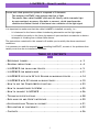
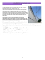
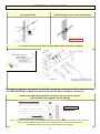
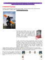
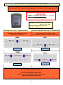
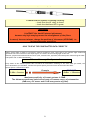
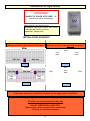
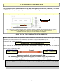
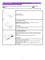
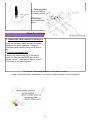
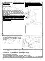
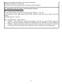
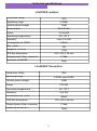
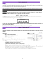
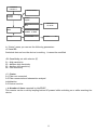
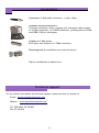
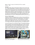
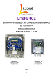
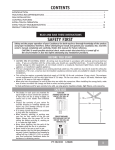
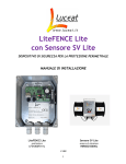
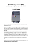
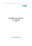
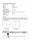
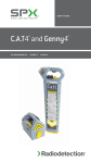
LITEFENCE SECURITY DEVICE FOR PERIMETER PROTECTION USER'S MANUAL L I T E F EN C E T R A N S M I T T E R 320. SIS . LF E N300F 011 T L I T E F EN C E ( A N A LY S E R ) 3 2 0 . S IS . LF E N3 0 0 F 0 1 1 S L I T E F EN C E L I T E ( A N A LY S E R ) 320. SIS . LF E N300F 011 L Rev.002 1 2 LiteFENCE - How it works Luceat anti-climb protection system is composed of 3 elements: The analyser LiteFENCE, that analyses the flow of light The plastic fiber cable LiteWIRE (with anti-UV filters), which transmits light An opto-mechanic accessory (like bolts or sensors), which transforms the vibration/oscillation/ flexion of the fence into a variation of the light signal It is important to make sure that the cable LiteWIRE is installed correctly, i.e.: it is fastened to the fence without introducing attenuation on the light signal; it is installed correctly to the fence by means of opto-mechanic accessories to detect attempts of climbing-over without false alarms. The instructions contained in this manual will enable you to satisfy the above mentioned conditions. It is necessary to read this manual before installing LiteFENCE, as most of the problems that usually occur are due to installation mistakes. TABLE OF CONTENTS - R EF ERENCE - G ENERAL FIGURES ................................................... P. PRECAUTIONS ................................................ P. 4 - L ITE FENCE FOR CHAIN - LI NK FENCES - L ITE FENCE FOR BARBED WIRE - L ITE FENCE L ITE WITH - L ITE FENCE SV WITH TO USE THE - H OW TO CONNECTORIZE - H OW TO CONNECT - T ECHNICAL .................................. P. 5 ........................................ P.11 SV L ITE S ENSOR ON MODULAR FEN CES SENSOR O N RIGID FENC ES - H OW 3 P OWER M ETER FUNCTION ......... P.14 ........................ P.19 ............................ P.23 L ITE W IRE ..................................... P.25 L ITE FENCE ........................................ P.26 SPECI FICATI ONS ............................................ P.28 - D ATA ANALYSIS - A CCESSORIES - D ECLARATION AND AND U SER ' S INTERFACE ................................. P.29 T ECHNICAL SUPPORT ................................ P.31 OF CONFOR MITY ......................................... P.32 - C ONTACTS ............................................................. P.36 3 Reference figures LiteFENCE analyser Power supply: 12-24VDC±10% max) Consumption: 200mA at 12VDC (2W Alarm output: 5A/240Vac NC Tamper: optical anti-tampering sensor Optical Power budget: -30dBm 250m* + 25 tension bolts) Fiber: LiteWIRE simplex anti-UV (max LiteFENCE transmitter --------------- LiteFENCE Lite analyser Protection rating Operating range Optical power budget Power supply Operating temperature Humidity Consumption at 12VDC Dimension in IP55 box Otptical connector out EMI/RFIiImmunity IP55 0-250m* (max 30dB) 30dB 9-12V±10% -20°+70°C 5 to 90% 80mA 115x160x60mm F-SMA total *distance reachable with a correct installation with fiber Plastic fiber (TX) Power Attenuation <0.1 dB/m at 525nm. (Sharp curves, cable ties or mechanical stress while placing the fiber can reduce the distance) 4 General precautions Plastic fiber is very resistant and does not break, but bends and angles may reduce, also significantly, the maximum distance of the system. Do not tread or walk on the cable LiteWire Do not pull hard on the cable LiteWire Minimum bending radius of 25mm LiteFENCE monitors the optical power constantly, so you can detect installation mistakes and install the system properly. (see: “How to use the power meter function”) 5 LiteFENCE for chain-link fences The plastic optical fiber is first “woven” along the fence, going in and out as shown in the figure. It is then affixed to the poles with tension bolts (one every 10m) and on the fence with cable ties (1every two meters or between the two poles). THE CABLE CROSSES THE MESH During an attempt to climb, the fence and cable bend due to the weight of the thief. This variation is read by the analyser that triggers the alarm via a NC relay contact which can be connected to any alarm control panel. Wind and vibrations caused by weather conditions and moving vehicles do not cause the fence to bend and so it does not trigger any alarm. For this reason, the installation of the perimeter protection system is simple and does not require the learning of any software program, ensuring a ‘stop to false alarms’. Depending on the required level of security, you can install on the fence: - 1 fiber to the centre (to detect climbing and breaking); - 2 fibers (0.5m and 1.5m from the ground up) to detect climbing and lifting; - 4 fibers (0.25m, 0.5m, 0.8m, 1.5m from the ground up) to create an impenetrable barrier even in the event the fence is cut. In general, for the protection of a chain-link fence, the following components are required: - 1 LiteFENCE analyser every 200/250m of plastic fiber cable LiteWIRE plastic fiber cable with UV protection 2 FSMA metal connectors every LiteFENCE analyser or coupler 1 tension bolt every 10m of fiber 1 cable tie every 2m of fiber 6 Examples of connection schemes for chain-link fences LiteFENCE analyzers can be connected separately or in daisy chain. Using the LiteFENCE transmitter, you can create a point-to-point link (with no need to close the loop) The jumper is usually inserted: this creates independent alarm zones (No.LiteFENCE=No. Alarm zones) on the entire perimeter; if the jumper is not inserted, the alarm will be transmitted throughout the length creating one single alarm zone( No. LiteFENCE=1 alarm zone) Loop connection (max 250m*) Point-to point connection using LiteFENCE Transmitter and LiteFENCE Analyser (max 250m*) Daisy chain devices point-to-point/loop (no distance limit) 7 Independent loops (no distance limit) *this distance is reachable with a correct installation with fiber attenuation <0.1 dB/m at 525nm. (Sharp curves, cable ties or mechanical stress while placing the fiber can reduce the distance) 8 Security levels on chain link fences Depending on the requried level of security and budget available, you can install 1, 2, or 4 fibers on the fence E.g. 200m* perimeter – 1 zone ANTI-CLIMIBING ANTI-BREAKTHROUGH 1 fiber connection: the fiber replaces the middle rod, which is removed. Only the upper and lower rods are present. Basic protection, but cheap solution; max. fence length is 200/250m* E.g. 400m* perimeter - 4 zones ANTI-CLIMBING ANTI-LIFTING Connection with 2 fibers, at 0.5m and 1.5m from ground up (on a 2m high fence) All the rods (upper, middle and lower) are present. Standard, recommended protection rate; max. fence length is 100/125m* E.g. 100m perimeter – 2 zones ANTI-CLIMBING ANTI-LIFTING ANTI-BREACH Connection with 4 fibers. At 0.25/0.50/0.80 and 1.5m from ground up, on a 2m high fence Highest protection: it creates a barrier which is difficult to be breached, even after the mesh has been cut; max. fence length is 50m* *this distance is reachable with a correct installation with fiber attenuation <0.1 dB/m at 525nm. 9 (Sharp curves, cable ties or mechanical stress while placing the fiber can reduce the distance) Installation on chain-link fences 1. Screw the bolt into the pole 2- Weave (enter/exit) the fiber through the mesh 1 bolt every10m (each bolt introduces a maximum attenuation of 0,10.2dB equal to about 1-2m LiteWIRE cable) THE CABLE CROSSES THE MESH 3. Connectorize the fiber and connect/power LiteFENCE analyser INITIALIZATION; yellow LED SYSTEM WORKING (RELAY: CLOSED); green LED SYSTEM IN ALARM (RELAY: OPEN); red LED 4- Set LiteFENCE to Power Meter mode To prevent increase of attenuation of the fiber during the installation of bolts and cable ties, it is VERY IMPORTANT to keep the optical power of the fiber constantly monitored. Keep the DOWN button pressed while you switch on the system, until a dashed line appears on the display 10 DOWN button N.B.: if you want to set the system to Power Meter mode when it has already been switched on, Reset the system: while you keep the DOWN button pressed, press the Reset button, and then release Reset first and DOWN afterwards. After a few seconds a dashed line will appear. HOW TO READ THE POWER METER DATA CORRECTLY Plastic optical fiber is made of a polymeric material realized in such a way that it can lead the light inside and guarantee the total reflection of the input signal, to transfer all the entering light to the exit. However, physical and technical factors occur (ties, tension bolts, eye bolts) and cause power losses along the fiber. That power loss is called attenuation. Attenuation = optical power loss Every meter of the installed plastic fiber introduces an attenuation resulting in: the more fiber you install, the more attenuation you introduce, and the less optical power you will receive at the end of the fiber. Optical power is measured in dBm. FIBER ENTRANCE 0 dBm = 0meters Example FIBER EXIT -10dBm = 100meters Maximum sensitivity of Luceat systems is 30dB. The distances mentioned take into account all common source of attenuation (9dB every SV sensor and 0.1dB every meter of fiber) 5- While you fasten the fiber to the bolts, keep the attenuation monitored with LiteFENCE (5mm hole and 8mm flare) ...or make the fiber pass IN FRONT of the Each tension bolt normally introduces an attenuation of 0.1 to 0.2 dB, pole (this, however, reduces the system which equals to about 1 to 2m of LiteWIRE cable sensitivity) If the power meter shows a higher attenuation value, make sure that the fiber is streight 11 For the poles where no bolt is screwed: use existing holes OR drill the pole and pass the cable through it 6- Tie the cable to the mesh between the poles using cable ties Tie NO fascetta STRETTA When you tighten the ties, monitor the attenuation values Cable ties shouldn't introduce any attenuation In case you notice an increase in attenuation, make sure that the fiber doesn't make folds OK 7 - Select sensitivity 12 RESET after every change of sensitivity F - MANUAL SENSITIVITY SELECTOR High Medium-low Medium-high Low G - RESET BUTTON 13 LiteFENCE for barbed wire On each barbed wire arm (usually one every 2m), a clip is attached using a self- drilling screw. The clip fastens the barbed wire and the plastic fiber together. The plastic fiber is passed through the front of the screw, preventing it from unscrewing, and is attached to the barbed wire with two cable ties near the barb arms (to approx. 10 cm from the clip) and with a third cable tie between the two barb arms. Any attempt to cut or bend the barbed wire (such as deformation due to the weight of a thief) is detected by the sensor which triggers the signal via the NC alarm output relay (connectable to any alarm control panel). We recommend the use of two rows of fiber attached to the lower barbed wire and to the upper barbed wire. In general, for the protection of a perimeter wall with barbed wire, the following components are required: - 1 LiteFENCE analyser every 200/250m of plastic fiber cable LiteWIRE plastic fiber cable with UV protection 2 FSMA metal connectors every LiteFENCE analyser or coupler 1 tension bolt every 10m of fiber 1 clip every barb arm 2 cable ties every barb arm and 1 cable tie every 2 barb arms 14 Installation on barbed wire 1- Fasten the barbed wire to the arm using the special clips 2- Thread the fiber into the clip hole, protecting the screw from unscrewing Plastic fiber 3. Connectorize the fiber and connect and power LiteFENCE analyser 4- Set LiteFENCE to Power Meter mode To prevent increase of attenuation of the fiber during the installation of bolts and cable ties, it is VERY IMPORTANT to keep the optical power of the fiber constantly monitored. Keep the DOWN button pressed while you switch on the system, until a dashed line appears on the display DOWN button N.B.: if you want to set the system to Power Meter mode when it has already been switched on, Reset the system: while you keep the DOWN button pressed, press the Reset button, and then release Reset first and DOWN afterwards. After a few seconds a dashed line will appear. 15 HOW TO READ THE POWER METER DATA CORRECTLY Plastic optical fiber is made of a polymeric material realized in such a way that it can lead the light inside and guarantee the total reflection of the input signal, to transfer all the entering light to the exit. However, physical and technical factors occur (ties, tension bolts, eye bolts) and cause power losses along the fiber. That power loss is called attenuation. Attenuation = optical power loss Every meter of the installed plastic fiber introduces an attenuation resulting in: the more fiber you install, the more attenuation you introduce, and the less optical power you will receive at the end of the fiber. Optical power is measured in dBm. FIBER ENTRANCE 0 dBm = 0meters FIBER EXIT -10dBm = 100meters Example Maximum sensitivity of Luceat systems is 30dB. The distances mentioned take into account all common source of attenuation (9dB every SV sensor and 0.1dB every meter of fiber) 5-Tie the fiber to the barbed wire (10cm before and 10cm after the clip) and midway between the 2 arms Do NOT OVERTIGHTEN the cable ties 6 - Select sensitivity F - MANUAL SENSITIVITY SELECTOR High Medium-low Medium-high Low G - RESET BUTTON 16 RESET after every change of sensitivity LiteFENCE Lite with SV Lite Sensor on modular fences (type Orsogril/Keller/Betafence/Pratika) Our SECURITY SYSTEM “SV” is patent pending For semi-rigid grating fencing panels (type Orsogril / Keller) and electrically welded panels (type Betafence / Pratika) with a minimum height of 145cm. The semi-rigid modular nets do not bend under the weight of the thief, but, rather, move back and forth along a single axis in response to the strain caused by the climbing over. Such fluctuations are detectable by attaching the SV Lite sensor to the fence (patent pending). In fact, in the SV Lite sensor, light passes through two fibers facing each other and is constrained to move only on one axis, the same as that in which the fence sways. In the event of climbing over, swaying causes the misalignment of the fibers, the light beam completely stops and the LiteFENCE Lite analyser, which analyses the light signal, recognizes this variation triggering the alarm. Simple vibrations resulting from weather conditions or moving vehicles fail to create a swing capable of completely stopping the light beam. Therefore the system has an excellent resistance to false alarms and does not require adjusting, new learning phases or software. Each SV Lite sensor detects oscillations up to 40m per side (depending on the type of fence) and protects up to 80m of straight fence. 17 In the case of fence curves, these will decrease the oscillations, so the use of more sensors will be required. All LiteFENCE analyzers and SV sensors are connected as shown in the figure. The plastic fiber is “woven” along the fence with an enter and exit process to prevent an entry attempt via the dismounting of a panel. Grating fence type Orsogril/Keller Electro-welded fence type Betafence/Pratika Each SV Lite sensor detects oscillations caused Each SV Lite sensor detects oscillations caused by climbing over up to 40m away (straight) in by climbing over up to 25m away (straight) in both directions. both directions. In general, for the protection of modular fencing, the following components are required: Grating fence type Orsogril/Keller Electro-welded fence type Betafence/Pratika - 1 SV Lite sensor every 80m of straight fencing (pre-cabled with 40+40m each sensor) - 1 SV Lite sensor every 50m of straight fencing (pre-cabled with 40+40m each sensor) - 1 LiteFENCE analyser every 2 SV Lite sensors - 2 FSMA metal connectors every analyser LiteFENCE Lite or coupler - 1 LiteFENCE analyser every 2 SV Lite sensors - 1 coupler every 2 SV Lite sensors - 2 FSMA metal connectors every analyser LiteFENCE Lite or coupler - 1 cable tie every 1.5m of fiber - 1 coupler every 2 SV Lite sensors - 1 cable tie every 1m of fiber 18 Installation on modular fences (h>145cm) The position of the SV Lite sensor (on the fence) influences the overall sensitivity: installing the SV Lite sensor to the upper part of the fence will increase sensitivity ATTENTION! HANDLE SV SENSOR WITH CARE (it contains precision machinery) Power source: completely passive Attenuation: 15dB with 2x40m plastic fiber (equal to 150m fiber) Protection Grade: IP68 in metal box Dimensions: 60x80xh150mm Grating fence (e.g. Orsogril/Keller) Electro-welded Fence (e.g. Betafence) The fence must be higher than145cm. Attach the SV Lite sensor to the upper part of the fence The fence must be higher than145cm. Attach the SV Lite sensor to the lower part of the fence or to the fence pole LiteFENCE Lite LiteFENCE Lite LiteFENCE Lite LiteFENCE Lite Pass the fiber (sewing) into the fence to avoid intrusion by panel removal DO NOT OVETIGHTEN CABLE TIES! Tighting too much increases fiber attenuation reducing the maximum distance 19 1- Attach the SV Lite sensor to the fence by using the brackets supplied and connect plastic fiber to the LiteFENCE Lite analyser Daisy-chain The jumper is usually inserted: this creates independent alarm zones (No.LiteFENCE Lite=No. Alarm zones) on the entire perimeter; if the jumper is not inserted, the alarm will be transmitted throughout the length creating one single alarm zone( No. LiteFENCE Lite=1 alarm zone) Daisy chain installation + single zone alarms 2-Power LiteFENCE Lite analyser Jumper 12Vdc Power/80mA Alarm LED Power ON LED Plastic fiber (RX) connector Alarm output (NC relay) Certification Plastic fiber (TX) connector part15 IP protection rate Optical power budget Optical output (relay) Power supply Operating temperature Humidity Power consumption Max power EMI/RFI 20Immunity Dimensions EMC2004/108/CE FCC verification level IP55 30dBm 0,2A/230vac 1a/24vdc +9/12vdc -20°c+50°c from 5 to 95% 80mA 1W Total 116x62x160 (with cable glands) 2 SV 1 Lite 3-Connect the two SV Lite sensors (with a coupler) and connect them to LiteFENCE Lite 4-Check that the system is working correctly - check that the NC relay is closed - check the the Alarm LED is green WARNING LiteFENCE Lite has NO internal adjustment because only high swaying causes the misalignment of the fibers. In case of incorrect alarms, change the position of the sensor (UP/DOWN) to increase/decrease sensitivity HOW TO READ THE POWER METER DATA CORRECTLY Plastic optical fiber is made of a polymeric material realized in such a way that it can lead the light inside and guarantee the total reflection of the input signal, to transfer all the entering light to the exit. However, physical and technical factors occur (ties, tension bolts, eye bolts) and cause power losses along the fiber. That power loss is called attenuation. Attenuation = optical power loss Every meter of the installed plastic fiber introduces an attenuation resulting in: the more fiber you install, the more attenuation you introduce, and the less optical power you will receive at the end of the fiber. Optical power is measured in dBm. FIBER ENTRANCE 0 dBm = 0meters Example FIBER EXIT -10dBm = 100meters Maximum sensitivity of Luceat systems is 30dB. The distances mentioned take into account all common source of attenuation (9dB every SV sensor and 0.1dB every meter of fiber) 21 L ITE FENCE WITH SV SENSOR ON RIGID FENCE Our SECURITY SYSTEM “SV” is patent pending For rigid fences higher than 115 cm. The fiber, normal or in a hybrid version (to power LiteFENCE analysers), is “woven” along the fence with an in and out process. In the SV sensor, light passes through two fibers facing each other. A vibration creates a misalignment of the fibers and a variation of the light intensity that the LiteFENCE analyser detects, in turn generating an alarm. LiteFENCE, compared to LiteFENCE Lite, is able to detect the partial misalignment of the fiber caused by a slight vibration and, therefore, detects vibrations up to 10/15m (for fences with a height between 110 and 145 cm) and up to 15/25m (for fences higher than 145cm per side), protecting up to 30/50m of a straight fence. In the case of fence curves, these will decrease the oscillations, so the use of more sensors will be required. Excellent tolerance to false alarms is guaranteed by the high frequency of vibrations caused by weather conditions and moving vehicles on this type of fence, filtered by the inertia of the SV sensor and LiteFENCE firmware. The parameters of LiteFENCE are pre-set in the factory according to the type of fence to protect (selectable from the menu); in order to conform to the specific requirements, however, the operator may adjust the following: - pre-alarm time (i.e. how long should an oscillation / vibration last before triggering the real alarm); - sensitivity level (high or low); - activation filter for high frequency vibrations All LiteFENCE analysers and SV sensors are connected as shown in the figure. The fiber, normal or in a hybrid version (to power LiteFENCE analysers), is “woven” along the fence with an in and out process. 22 In general, for the protection of modular fencing, the following components are required: Height of fence: 115 cm to 145cm Height of fence: over 145cm - 1 LiteFENCE analyser every 60m of plastic - 1 LiteFENCE analyser every 100m of plastic fiber cable fiber cable - 1 SV sensor every 30m of plastic fiber - 1 SV sensor every 50m fiber - LiteWIRE plastic fiber cable with UV protection - LiteWIRE plastic fiber cable with UV protection - 2 metal connectors for each LiteFENCE - 2 FSMA metal connectors every LiteFENCE analyser or coupler analyser or coupler - 1 cable tie every 1m of fiber - 1 cable tie every 2m of fiber 23 Installation on rigid fences ATTENTION! HANDLE SV SENSOR WITH CARE! (it contains precision machinery) Power source: completely passive Attenuation: 9dB (equal to about 90m of fiber) Protection rate: IP68 in metal box Dimensions: 50x83x178mm INSTALLATION EXAMPLES Height of fence ≥145 cm Height of fence ≥110 cm If the fence is higher than 145cm, attach the SV sensor to the lower part of the fence If the fence is higher than 110cm, attach the SV sensor to the upper part of the fence 30m max 50m max 15m max 25m max 15m max 25m max LiteFENCE LiteFENCE 100m max 60m max 30m max 15m max 25m max 100m 50m max max 25m max LiteFENCE LiteFENCE The position of the sensor (on the fence) influences the sensitivity: To increase sensitivity, install the SV sensor on the upper part of the fence Pass the fiber (weaving) into the fence to avoid intrusion by panel removal The fiber can be fastened with cable ties DO NOT OVERTIGHTEN CABLE TIES! Tightening too much increases fiber attenuation reducing the maximum distance 24 15m max 1- Attach the SV sensor to the fence by using the brackets supplied and connect the plastic fiber to the LiteFENCE analyser 2 SV Sensors 1 LiteFENCE 1 SV Sensor 1 LiteFENCE Daisy-chain Before fastening cable ties, set LiteFENCE to Power meter mode, so you'll constantly monitor the attenuation of the fiber during the installation, to identify and avoid any increase of fiber attenuation The jumper is usually inserted: this creates independent alarm zones (No.LiteFENCE SV=No. Alarm zones) on the entire perimeter; if the jumper is not inserted, the alarm will be transmitted throughout the length creating one single alarm zone( No. LiteFENCE SV=1 alarm zone) 2-Power LiteFENCE Insert cables and fibers through the cable glands before you conectorize them. In case of armoured cables, connect Their shield to the ground. 25 26 3- Set LiteFENCE to Power Meter mode To prevent increase of attenuation of the fiber during the installation of cable ties, it is VERY IMPORTANT to keep the optical power of the fiber constantly monitored. Keep the DOWN button pressed while you switch on the system, until a dashed line appears on the display DOWN button N.B.: if you want to set the system to Power Meter mode when it has already been switched on, Reset the system: while you keep the DOWN button pressed, press the Reset button, and then release Reset first and DOWN afterwards. After a few seconds a dashed line will appear. HOW TO READ THE POWER METER DATA CORRECTLY Plastic optical fiber is made of a polymeric material realized in such a way that it can lead the light inside and guarantee the total reflection of the input signal, to transfer all the entering light to the exit. However, physical and technical factors occur (ties, tension bolts, eye bolts) and cause power losses along the fiber. That power loss is called attenuation. Attenuation = optical power loss Every meter of the installed plastic fiber introduces an attenuation resulting in: the more fiber you install, the more attenuation you introduce, and the less optical power you will receive at the end of the fiber. Optical power is measured in dBm. FIBER ENTRANCE 0 dBm = 0meters Example FIBER EXIT -10dBm = 100meters Maximum sensitivity of Luceat systems is 30dB. The distances mentioned take into account all common source of attenuation (9dB every SV sensor and 0.1dB every meter of fiber) Each LiteFENCE tolerates a maximum attenuation of 30dB, equal to 2 SV sensors (equal to 15dB each) and 100m* of plastic fiber LiteWIRE *this distance is reachable with a correct installation with fiber attenuation <0.1 dB/m at 525nm. (Sharp curves, cable ties or mechanical stress while placing the fiber can reduce the distance) 27 4-Set the sensitivity Default setting of LiteFENCE is: height ≥145cm pre-alarm time is 5s filter is ON In case of special environmental conditions or if you want to have different sensitivity performances you can reset these values from the menu Press the “DOWN” button to enter the menu RESET after every change of sensitivity Press DOWN to access the configuration OK 1-Thresholds: select fence type and height (110 for rigid or over 110cm fence / 145+ for semirigid or over 145cm fences OK 2-Time Window: pre-alarm time before alarm goes off (from 0.1 to 10 sec.) OK 3-Input filter: high frequency filter (“OFF” only if you want to detect vibrations on very rigid fences) SUGGESTED PRESET Fence height Detection from XXX to XXX SENSITIVITY PRE-ALARM TIME FILTER 110cm ≥145cm From 15 to 25m* each side From 25 to 40m* each side S3 S3 0,1 sec 5,0 sec Off On *These distances are approximate and may vary depending on the type of fence and its propagation of vibrations/ocillations 28 How to connectorize Litewire FIRST insert the cables into the cable gland of the water tight box, THEN crimp the connectors. All the tools required to install a connector can be found in the Litewire connectorization kit. 1- Cut the fiber with any cutting tool. 2 – Remove the jacket Remove about 1 cm of jacket. The jacket of the optical cable has a diameter of 2.2mm. The fiber has a diameter of 1 mm. ATTENTION! Use a standard cable stripper with a hole of 1.0 mm or more, so you will not damage the fiber. 3 – Crimp the connector Insert the protection boot. Insert the FSMA connector onto the cable till the jacket stops against the connector; the fiber should come 2mm out of the connector. Crimp the FSMA connectors on the cable jacket. ATTENTION! The connector must be crimped on the cable jacket and must not be crimped directly on the fiber. The crimp tool for FSMA connectors must have a hexagonal crimping diameter of 3mm. In case you use a Luceat crimp tool (SMAT.001.M22M), use the 0.122” hole. 29 4 – Fiber polishing Level the fiber by polishing the connector on sand paper using the metal polishing disc. ATTENTION! You should make some "8"-shapes with the connector on the sand paper. How to connect LiteFENCE 1- Connect the cable Litewire to the device Insert the Litewire cables through the cable glands of the water tight box, crimp the connectors and connect them to the device (B). 2-Connect the alarm zone Connect the alarm zone (D) of the alarm panel; in case the LiteFENCE devices are placed “in bus”, only the last device will be connected to the alarm system. The circuit is normally closed, so the relay is closed. In case of disconnection, cable break, no power or cable bending, the circuit opens. 30 3- Connect power supply (e.g.from the battery of the alarm panel) Connect the power supply (A) 4- Connect the alarm relay (10A to 240VAC) to the alarm system; you can place the anti-tampering resistance in series. (see previous figure). The yellow led glows for some seconds and the green led glows. From this moment on, the transmission port (Tx) emits codified light signals which pass through the plastic optical fiber and arrives at the receiving port (Rx). The device will continually control the power of the signal received. When the device detects a difference in power, due to cable cut or bendings on the fiber, an alarm will go off. The alarm status is shown on the display and with the glowing red led. 5-Sensitivity adjustment This device has 4 sensitivity settings you can select according to your application using the selector (F). The intermediate levels can be used to decrease the system sensitivity in case, for example, of alarms due to bad weather conditions or to increase the protection level. After changing sensitivity, RESET the system using the reset botton(G). 6-a Installation with bolts and clips: Set the analysis interval Menu→Configuration→ Time window You can set the analysis interval of the light signal. Range:1s to 60s. The analyser compares the current attenuation rate to the attenuation rate of 1 to 60 seconds 31 before, and triggers the alarm if the rates are different. Standard interval: 20 or 60 seconds. Set a short interval in case you want to reduce unwanted alarms. 6-b. Installation with SV sensor: Set the analysis interval Menu→Configuration→ Time window You can set the analysis interval of the light signal. Range: 0.1s to 10s. If the variation of the light signal last over that interval, there will be an alarm on the NC contact. Standard interval: 1 second. Menu →Configuration →Type of fence 1. Orsogril – lower sensitivity: choose this setting if the fence is type Orsogril, about 2m high, or if the fence easily transmits the oscillations due to climbing over a long distance 2. Standard – higher sensitivity: choose this if the fence is very low, very rigid or, in general, if the fence scarcely transmits the oscillations due to climbing over a long distance 32 Technical specifications LiteFENCE analyser Protection rating IP55 Operating range 0-250m Optical power budget 30dB Alarm output 5A/240 VAC Power 12-24±10% Operating temperature -20°+70°C Humidity Consumption at 12VDC from 5 to 90% 140mA Max. power 2W Weight in IP55 box 194g IP55 Box dimensions 220 x 255 x 90 mm Output plastic fiber connector F-SMA Immunity to EMI/RFI Total LiteFENCE Transmitter Protection rating IP55 Operating range 0-250m (max 30dB) Optical power budget 30dB Power 12V±10% Operating temperature -20°+70°C Humidity 5 to 90% Consumption at 12VDC 80mA IP55 Box dimensions 115 x 160 x 60 mm Output plastic fiber connector F-SMA Immunity to EMI/RFI Total 33 Data Analysis LiteFENCE continually logs the attenuation rates over the cable as well as alarms, recording them to an SD memory card (E). Date and time are already set. After one month of operation, you can send the SD memory card in the device to Luceat: we will give you free support about the most appropriate level of sensitivity that should be selected on the device. For this reason, there are 2 SD memory cards in the package. WARNING: the files reporting the logs can only be read by a special software of Luceat. Do not try to open the SD memory card, as all data could be cancelled. ALERT “Link is too long” LiteFENCE indicates when the maximum link length or the maximum attenuation rate has been reached with the following alert on the display. ATTENTION! LINK IS TOO LONG In this case, the system keeps operating correctly, but we recommend turning down sensitivity in order to avoid false alarms. Sensitivity can be adjusted using the selector (F), as shown on page 27. User's interface LiteFENCE features a text interface which you can access using the button on the right of the display. Functions: Up - menu scroll upwards Down - menu scroll downwards OK - option selection ESC - menu exit The tree structure will be explained in the next section. Sub-menus: Firmware: shows current firmware version Language: language can be selected Clock: shows date/time, which can also be set Status: reports statistical data on how the device is working Settings: you can set the analysis interval of the light signal attenuation. The variation of this parameter detects attenuation variations in different intervals. Rates range from 1s (default: lowest sensitivity) to 60s (highest sensitivity). 34 LiteFENCE Luceat S.r.l. Version FW 0,9 Firmware Language < Italiano English Set Show Clock Status Settings < < 04/01/10 12:22.59 < < P1=127 S1 P2=087 S=00001 A=0054 Time window < Seconds: 01 In “Status” menu you can see the following parameters • P1 and P2 : Statistical data on how the device is working – it cannot be modified •S1: Sensitivity set with selector (F) S1 = High sensitivity S2 = Medium-high sensitivity S3 = Medium-low sensitivity S4 = Low sensitivity • S : Status S=1 Fiber not connected S=2 Fiber connected and attenuation analysis/ initialization S=3 Device is active • A: Number of alarm reported by LiteFENCE This counter can be re-set by keeping button UP pressed while switching on or while resetting the device. 35 Accessories Connectors: F-SMA metal connectors , 1 pack= 10pcs LiteWIRE connectorization kit Tool-case containing: cutter, crimping tool, automatic cable stripper, no.5 FSMA connectors, no.5 HFBR connectors, polishing discs for FSMA and HFBR, 1000 grit sand paper Coupler for F-SMA splices. Each splice also requires no.2 FSMA connectors. Tensioning bolt for installations on chain link fences Clip for installations on barbed wire Technical support For any further information and technical support, please feel free to contact us: E-mail : [email protected] Website : www.cyprusalarmsystems.com Tel. 7000 4002, 25 748 830 Fax: 25 108 616 36 81, Ellados Str, 3041, Limassol, Cyprus Phones: 7000 4002, 25 748 830 Fax: 25 108 616 Email: [email protected] Website: www.cyprusalarmsystems.com 37