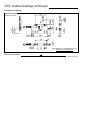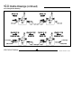
1
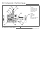
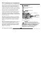
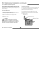
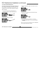
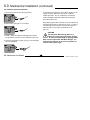
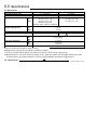
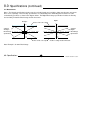
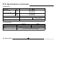
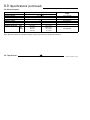
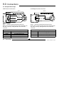
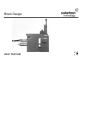
Block Gauge
user manual
1.0: Index
Section
Title
1.0
Index . . . . . . . . . . . . . . . . . . . . . . . . . 1
Section
Title
2.0
Safety Summary . . . . . . . . . . . . . . . . . 2
8.2
Mechanical . . . . . . . . . . . . . . . . . . . . . 14
3.0
Introduction . . . . . . . . . . . . . . . . . 3
8.3
Environmental . . . . . . . . . . . . . . . . . . 14
4.0
Components of the Block Gauge . . . . . . . . 4
8.4
Electrical Interface. . . . . . . . . . . . . . . . 15
5.0
Care of the Block Gauge . . . . . . . . . . . 5
9.0
Connections . . . . . . . . . . . . . . . . . . . .16
6.0
Mechanical Installation . . . . . . . . . . . . 6
9.1
Analogue Block Gauge . . . . . . . . . . . .16
6.1
Tip Installation/Replacement . . . . . . . . 7
9.2
Digital Block Gauge . . . . . . . . . . . . . . 17
6.2
Tool Holder Installation/Adjustment . . . . . . 8
10.0
Outline Drawings . . . . . . . . . . . . . . . . 18
6.3
Spring Installation/Adjustment . . . . . . . . . 9
10.1
Mechanical Drawings . . . . . . . . .. . . . . 18
6.4
Pneumatic Actuator Installation . . . . . . 10
10.2
Configuration Drawing . . . . . . . . . . . . 21
7.0
Maintenance . . . . . . . . . . . . . . . . 11
Return of Goods
7.1
Sensor Replacement . . . . . . . . . . . . 11
Solartron Sales Offices
8.0
Specifications . . . . . . . . . . . . . . 12
8.1
Measurement . . . . . . . . . . . . . . . 12
1.0 Index
Page
1
Page
Part No. 501512 Issue 5
2.0: Safety Summary
Terms in this Handbook
WARNINGS:
WARNING statements identify conditions or practices
Do not operate in an explosive atmosphere
that could result in personal injury or loss of life.
To avoid explosion, do not operate this equipment in
an explosive atmosphere.
CAUTION statements identify conditions or practices
that could result in damage to the equipment or other
Air Pressure
property.
Under no circumstances should the recommended
maximum overpressure of 7 bar be exceeded when
using pneumatics with the Block Gauge.
NOTES:
This equipment contains no user serviceable parts
Symbols in this manual
This symbol indicates where applicable
This equipment must be returned to your Solartron
cautionary or other information is to be found.
dealer for all servicing and repair (see section 10/11).
Low Voltage
This equipment operates at below the SELV and is
therefore outside the scope of the Low Voltage
Directive.
2.0: Safety Summary
2
Part No. 501512 Issue 5
3.0: Introduction
The Block Gauge family makes precision measurements of bores
and cavities a simple and reliable process. The use of these
devices is ideal in applications where space is limited and where
the use of axial probes is not possible.
Both digital and analogue versions of the Block Gauge are
available, with measurement ranges of 2mm, 5mm or 10mm.
The analogue versions can be used with standard conditioning
electronics.
The digital versions are designed to be connected directly onto
the Orbit Measurement Network, a modular system enabling fast
and versatile connection of multiple probes.
3.0: Introduction
3
Part No. 501512 Issue 5
4.0: Components of the Block Gauge
Key
1 Sensor
2 Sensor Grub Screw
3 Sensor Grub Screw
4 Pneumatic Actuator
5 Spring Holder
6 Spring
7 Tool Holder
8 Tip Carrier
9 Tip
10 Tip Carrier Grub Screw
11 Caphead Screw
4.0 Components of the Block Gauge
4
Part No. 501512 Issue 5
5.0: Care of the Block Gauge
The Block Gauge is a rugged parallel motion Universal
Gauge designed to withstand the rigours of an industrial
manufacturing environment. However, care should be
taken during installation to avoid dropping the Block
Gauge or subjecting it to severe shock loads.
In order to avoid damage to the linear bearings, it is
important not to exceed the specified torque setting (1.5
to 2Nm) of the fixing screw (11) when adjusting the tool
holder (7).
The contact tip (9) should be fitted to the tip carrier (8)
and tightened before the tip carrier is fitted to the tool
holder. Tip carriers are available in 20mm, 30mm and
40mm versions.
5.0 Care of the Block Gauge
5
Part No. 501512 Issue 5
6.0: Mechanical Installation
First establish the orientation in which the Block Gauge
will be used. The choice of return spring (6) and its
position depends on the orientation of the gauge and
should be made after the tool holder (7) and contact tip
(9) have been fitted. A set of return springs (for different
measurement forces) are included with each gauge.
Tip (9)
Tip Carrier (8)
Tool Holder (7)
It may be easier to set contact tip forces as close as
possible to operating forces before the Block Gauge is
installed onto a machine or fixture. Final adjustments
may then be made after installation. Final adjustment of
the spring force is made by winding the spring holder (5)
in or out. (section 5.3)
Sensor (1)
Pneumatic
Actuator (4)
When fitting a pneumatic actuator (4), ensure that the
threads in the Block Gauge and the actuator are clean.
In order to avoid damage to the actuator or the Block
Gauge, it is important not to exceed the specified air
pressure.
Spring Holder (5)
Return Spring (6)
Anti rotation adjustment
When mounting the Block Gauge in a fixture, care must
be taken not to drop the gauge or apply excessive
shocks which may degrade performance. It should be
secured by using the fixing screws at the base of the
Block Gauge. The fixing screws are M6. The thread
depth in the body is 8mm.
6.0: Mechanical Installation
CAUTION
The pneumatic Block Gauge works at a
higher air pressure than pneumatic Gauging
Probes. In order to avoid damage to
Gauging Probes when used in conjunction with
Block Gauges, it is important that separate
regulators are used for each product.
6
Part No. 501512 Issue 5
6.0: Mechanical Installation (continued)
6.1: Tip Installation/Replacement
To avoid placing strain on the tool holder (7) and the
Block Gauge frame, the tip carrier (8) should be
removed from the tool holder before fitting or removing a
tip (9).
Tip Installation
1. Screw the tip (9) into the tip carrier (8).
2. Position the tip carrier in the tool holder (7).
The Block Gauge tool holder allows the Block Gauge tip
and tip carrier to be mounted in one of three different
planes for maximum flexibility.
3. Tighten the 2.5mm tip carrier grub screw (10). Take
care not to overtighten it.
Tip Removal
Tip (9)
1. Loosen the 2.5mm tip carrier grub screw (10) which
holds the tip carrier (8) in place.
2. Remove the tip carrier from the tool holder (7).
Tip Carrier (8)
3. Unscrew the tip (9) from the end of the tip carrier.
Tip Carrier Grub Screw (10)
Tool Holder (7)
6.0: Mechanical Installation
7
Part No. 501512 Issue 5
6.0: Mechanical Installation (continued)
6.2: Tool Holder Installation/Adjustment
The tool holder is infinitely adjustable along the industry
standard dovetail fitting on the Block Gauge frame. This
dovetail fitting ensures that the gauge is rigid yet easy to
install and adjust.
Tool Holder Installation
To remove the tool holder (7), loosen the caphead screw
(11) located on the tool holder using a 3mm Allen key.
Slide the tool holder off the dovetail.
Tool Holder Adjustment
To re-install the tool holder, simply slide it over the
dovetail joint to the required position and then tighten
the caphead screw.
1. Loosen the caphead screw (11) located on the tool
holder (7) using a 3 mm Allen key.
Tool Holder (7)
2. Slide the tool holder to the required position.
3. Tighten the screw.
Caphead Screw (11)
Dovetail Fitting
CAUTION
In order to avoid damage to the linear
bearings, it is important not to exceed the
specification for the torque setting (1.5 to 2Nm) of
the fixing screw when adjusting the tool holder.
6.0: Mechanical Installation
8
Part No. 501512 Issue 5
6.0: Mechanical Installation (continued)
6.3: Spring Installation/Adjustment
The choice of spring return and its position depends on
the orientation of the gauge and should be made after
the tool holder and contact tip have been fitted. (See
section 6.2). A set of four return springs are included
with each gauge.
3. Select an appropriate spring, and insert this into the
frame.
1. Unscrew and remove the spring holder (5) or
pneumatic actuator (4) if this was being used.
4. Insert the screw holder back into the Block Gauge
frame and screw in.
5
4
2. Remove the spring (6) if installed.
5. Final adjustment to the spring force is made by
winding the spring holder in or out using a flat blade
screwdriver.
6
Refer to section 10.2 for information on the configuration
of the spring and pneumatic actuator.
6.0: Mechanical Installation
9
Part No. 501512 Issue 5
6.0: Mechanical Installation (continued)
6.4: Pneumatic Actuator Installation
1. Unscrew and remove the spring holder (5).
To maximise the working life of the Block Gauge, the air
supply should be both clean and dry for continual
reliable operation. The air should have a maximum
relative humidity of 60% RH and be filtered to better
than 5µm particle size.
5
When fitting a pneumatic actuator, ensure that threads in
the Block Gauge and the actuator are clean. In order to
avoid damage to the actuator or the Block Gauge, it is
important not to exceed the specification for air
pressure.
2. Remove the spring (6) if it is installed.
6
CAUTION
The pneumatic Block Gauge works at a
higher air pressure than pneumatic gauging
probes. In order to avoid damage to gauging probes
when used in conjunction with Block Gauges, it is
important that separate air pressure regulators are
used for each product type.
3. Install a spring and spring holder opposite to where
the pneumatic actuator is to be installed (section 5.3).
4. Insert the pneumatic actuator (4) and screw until tight.
Do not overtighten.
4
6.0: Mechanical Installation
10
Part No. 501512 Issue 5
7.0: Maintenance
7.1 Sensor Replacement - Analogue Version Only
3. Adjust the spring holder (5) opposite the sensor so
that there is a small gap of approximately 0.25mm
between the T-piece and the frame (see below).
Sensor Removal
1. Loosen the two sensor grub screws (2 & 3) which
hold the sensor (1) in place.
T-piece
2. Gently ease the sensor away from the frame. Care
must be taken not to damage the core or the gaiter
during removal.
Sensor (1)
Adjustment of
spring holder
Small Gap of approx. 0.25mm
Sensor Grub Screw (3)
4. Move the T-piece in by 2.65mm. The T-piece must
remain fixed in this position during the setting of
electrical null.
Sensor Grub Screw (2)
5. Connect an oscillator supply to the sensor.
Sensor Installation
6. Monitor the output of the sensor on a DVM.
1. Insert the replacement sensor (1) into the Block
Gauge frame. Care must be taken not to damage the
core or the gaiter during insertion. The carrier must
not protrude from the T-piece.
7. Adjust the position of the sensor relative to the frame
to achieve minimum output on the DVM. Care should
be taken not to rotate the sensor during this
adjustment. This is electrical null.
2. Tighten sensor grub screw (3), but leave screw (2)
loose.
7.0: Maintenance
8. Tighten sensor grub screw (2).
11
Part No. 501512 Issue 5
8.0: Specifications
8.1: Measurement
Measurement Range (mm)
Mechanical Travel (mm)
Accuracy(1)
Repeatability
(on-axis at 70 g tip force)
2mm
5mm
10mm
2mm
5mm
10mm
Resolution
Null Position
Tip Force(2)
Temperature Coefficient
Life
2mm
5mm
10mm
2mm
5mm
10mm
Analogue
±1.0, ±2.5 and ±5
3, 6 and 11
±1.0 µm or ±0.5% x D
±2.5 µm or ±0.5% x D
±5.0 µm or ±0.5% x D
(whichever the greater)
at 5kHz for LVDT, at 10kHz for half bridge
0.25 µm
0.25 µm
0.50 µm
Dependent on Electronics
Adjustable
Digital
2, 5 and 10
3, 6 and 11
±0.1 µm ±0.1% x D
±0.1 µm ±0.15% x D
±0.1 µm ±0.15% x D
User selectable to < 0. 1(µm)
Do Not Adjust
0.75 N minimum
± 0.2 µm/°C
± 0.5 µm/°C
± 1.0 µm/°C
Better than 5 million measuring cycles (dependent on application)
Accuracies quoted are through the gauge centreline.
Unplugged (free lead) and other specification available on request.
(1) Accuracy includes both linearity and sensitivity errors (D is the distance from setting master).
(2) Maximum tip force is 3.5N. A selection of springs can be supplied for attitude and dead wight compensation. Care
should be taken as the probe performance (accuracy and repeatability) may degrade at high tip forces.
8.0: Specifications
12
Part No. 501512 Issue 5
8.0: Specifications (continued)
8.1: Measurement
Note 1: The linearity specification includes errors due to both linearity and sensitivity. Other manufacturers may quote
these errors separately. These linearity specifications are substantially more demanding than the 0.25% full scale
conventionally specified, as shown in the diagram below. The Digital Block Gauge specification includes the linearity
and sensitivity for both the Block Gauge and the electronics.
Analogue
Solartron
Analogue
Block Gauge -2.5
Specification
-2.0 -1.5 -1.0 -0.5
12.5
10.0
7.5
5.0
2.5
0
-2.5 0.5
Digital
0.25% of full scale output
µm
µm
12.5
10.0
7.5
5.0
2.5
1.0
1.5
2.0
2.5
mm
0.0
0.5
-5.0
-7.5
-10.0
-12.5
0.25% of full scale output
1.0
1.5
2.0
3.0
-2.5
-5.0
-7.5
-10.0
-12.5
3.5
4.0
4.5
mm
5.0
Solartron
Digital
Block Gauge
Specification
Assumes setting master at mid stroke
Note: Example is for 5mm Block Gauge
8.0: Specifications
13
Part No. 501512 Issue 5
8.0: Specifications (continued)
8.2: Mechanical
Analogue
2mm
5mm
10mm
Mass of moving parts (g / lbs) 2mm
5mm
10mm
Material
IP Rating
Mass (g / lbs)
(Without toolholder)
Operating Pressure
Digital
160 g (0.352 lbs)
390 g (0.858 lbs)
385 g (0.847 lbs)
35 g (0.077 lbs)
90 g (0.198 lbs)
95 g (0.209 lbs)
Stainless Steel (300 Series) with Viton® Gaiters
IP65
IP65
IP43 for electronics
1 bar to 3 bar
7.3: Environmental
Storage Temperature (°C)
Operating Temperature (°C)
Shock
8.0: Specifications
Analogue
Digital
-40 to +85
-20 to +70
+5 to +85
+5 to +65
To maintain best performance, the Block Gauge should be protected
from excessive shock loads and dropping
14
Part No. 501512 Issue 5
8.0: Specifications (continued)
8.4: Electrical Interface
Analogue
LVDT
Energising Voltage
Energising Frequency
Energising Current
Calibration Voltage
Calibration Frequency
Calibration Load
Sensitivity (mV/V/mm)
2mm
5mm
10mm
Half Bridge
1 to 10 Vrms
2 to 20 kHz
2 mA/V at 5 kHz
2 mA/V at 10 kHz
3V
5 kHz
10 kHz
10 KW
2 KW
200 ±0.5%
73.5 ±0.5%
80 ±0.5%
29.4 ±0.5%
40 ±0.5%
14.7 ±0.5%
at 5 kHz
at 10 kHz
Digital
5 V ± 0.25 Vdc
Not Applicable
55 mA at 5 VDC
Not Applicable
Not Applicable
Not Applicable
Not Applicable
Note: Operation outside of calibration voltage, frequency and load may degrade performance.
8.0: Specifications
15
Part No. 501512 Issue 5
9.0: Connections
9.1: Analogue Block Gauge
LVDT Electrical Connections
Half Bridge Electrical Connections
Black
Black
Cable Screen
LVDT
+
Yellow
Case
-
Cable Screen
White
Green
Half
Bridge
3
4
5
Blue
2
Yellow
1
Case
Red
Note 1: + indicates forward movement of the tip.
Note 2: The transducer body may be disconnected from
the cable screen by cutting the black wire inside the
connector.
-
3
4
2
5
1
Red
Note 1: + indicates forward movement of the tip.
Note 2: The transducer body may be disconnected from
the cable screen by cutting the black wire inside the
connector.
LVDT Electrical Connections
Red & Blue
Energising
Green & White
Signal
Yellow
Secondary Centre Tap
Red & White
In Phase for Inward Displacement
Black
Transducer Body Ground
9.0: Connections
+
Half-Bridge Electrical Connections
Red & Blue
Energising
Yellow
Signal
Red & Yellow
In Phase for Inward Displacement
Black
Transducer Body Ground
16
Part No. 501512 Issue 5
9.0: Connections (continued)
9.2: Digital Block Gauge
PIE Pin assignment
Pin
Function
1
(none)
2
RS485(A)
3
RS485(B)
4
0V
5
0V
6
+5V
7
+5V
8
+5V
9
0V
9.0: Connections
PIE can be fitted directly into the back of the Digital
Readout or linked into the ‘Orbit’ Network using the
stackable T-CON connectors.
17
Part No. 501512 Issue 5
10.0: Outline Drawings
10.1: Mechanical Drawings
2mm Block Gauge
eg DK/2/S, BG/1/S
CAD drawings can be downloaded from
www.solartronmetology.com
10.0:Outline Drawings
18
Part No. 501512 Issue 5
10.0: Outline Drawings (continued)
10.1: Mechanical Drawings
5mm Block Gauge
eg DK/5/S, BG/2.5/S
CAD drawings can be downloaded from
www.solartronmetology.com
10.0:Outline Drawings
19
Part No. 501512 Issue 5
10.0: Outline Drawings (continued)
10.1: Mechanical Drawings
10mm Block Gauge
eg DK/10/S, BG/5/S
CAD drawings can be downloaded from
www.solartronmetology.com
10.0:Outline Drawings
20
Part No. 501512 Issue 5
10.0: Outline Drawings (continued)
10.2: Configuration Drawing
10.0:Outline Drawings
21
Part No. 501512 Issue 5
Return of Goods
Devices returned for service/repair/calibration should be
shipped prepaid to your distributor or, if purchased
directly from Solartron Metrology, to the relevant Sales
Office (see below).
The shipping container should be marked: "For the
Attention of the Returns Department"
The following information should accompany the
device(s):
1. Contact details of company/person returning device,
including return shipping instructions.
repair. Customer damage and any device found, upon
inspection, to have no fault will be considered nonwarranty.
Please contact the Sales Office or Distributor for
warranty terms, service options and standard charges.
Adherence to these procedures will expedite handling of
the returned device and will prevent unnecessary
additional charges for inspection and testing to
determine the condition.
Solartron Metrology reserves the right to repair or
replace goods returned under warranty.
2. A statement of service required and purchase order.
3. Description of the device fault and the circumstances
of the failure, including application environment and
length of time in service.
4. Original purchase order number and date of
purchase, if known.
Please note: A standard assessment charge is
applicable on all non-warranty devices returned for
All repairs are guaranteed for 3 months (unless
otherwise stated).
Solartron Metrology reserves the right to make changes
without further notice to any products herein to improve
reliability, function or design. Solartron Metrology does
not assume any liability arising out of the application or
use of any product or circuit described herein, neither
does it convey any licence under patent rights nor the
rights of others.
SOLARTRON METROLOGY OFFICES
OFFICES WORLDWIDE - Addresses for Repairs
France
Germany
United Kingdom
U.S.A.
Solartron Metrology
Z.I. du Bois Chaland
2, rue du Bois Chaland
CE 5611 Lisses
Evry Cedex, 91056
Solartron Metrology
Wittekindstrasse 12
45470
Mülheim/Ruhr
Solartron Metrology
Steyning Way
Bognor Regis
West Sussex
PO22 9ST
Solartron Metrology
10770 Hanover Road
Forestville
NY 14062
Tel: +33 (0) 1 69 64 47 47
Fax: +33 (0) 1 69 64 47 49
Tel: +49 (0) 208 31026
Fax: +49 (0) 208 31441
Tel: +44 (0) 1243 833333
Fax: +44 (0) 1243 833332
Tel: +1 (716) 965 4100
Fax: +1 (716) 965 4144
[email protected]
[email protected]
[email protected]
[email protected]
www.solartronmetrology.com
Solartron Metrology Ltd. is a subsidiary of The Roxboro Group Plc.
Solartron pursues a policy of continuous development. The specifications in this document may therefore be changed without notice
Solartron Metrology. A Roxboro Group Company