1
3 6 0 d e g re e In c lin o m e te r
MSENS-IN360
User's Manual
309-3, Yangno-ri, Bibong-myeon, Hwaseong-si, Gyeonggi-do, Korea [445-842]
http://www.das-co.com T) +82-31-356-3541, F) +82-31-356-3572
Contents
1. Introduction ······················································································································· 1
2. Specification ······················································································································ 1
2.1. Dimensions ················································································································· 1
2.2. Technical Specification ···························································································· 1
3. Wiring ································································································································· 3
3.1. RS-485 Wiring ··········································································································· 3
3.2. Analog mA Wiring ··································································································· 3
4. Communication and Command ··················································································· 4
4.1. Communication Settings ························································································· 4
4.2. Command ··················································································································· 4
5. Software ····························································································································· 8
5.1. Software manual ······································································································· 8
360degree Inclinometer MSENS-IN360
User's Manual
Before using
1. This equipment is versatile as a tilt sensor, use the following information to be checked.
2.
Check used to test the power. 10 ~ 30Vdc voltage is used. In noisy environments must be
connected to the ground.
3.
Tilt sensor is a gravity-based equipment is measured. This is based on the direction of gravity.
Please check the directions.
4.
Connect the correct cable to determine the index, please. Incorrect connection may result in
damage of the equipment.
5. 1 year warranty on this product.
309-3, Yangno-ri, Bibong-myeon, Hwaseong-si, Gyeonggi-do, Korea [445-842]
http://www.das-co.com
T) +82-31-356-3541, F) +82-31-356-3572
360degree Inclinometer MSENS-IN360
User's Manual
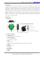
1. Introduction
MSENS-IN360 uses a three-axis acceleration sensor. This can be measured in all directions, and
measuring the angle 360 degrees, so there is no limit measure. 3-axis acceleration sensor mutual
temperature compensation. Microprocessor is equipped with 3 poly-fit look with high precision
and linearity. The user settings can be stored in internal memory of sensor. (direction, the
analog output range, the sensor ID, specify the initial value, etc.) In addition, because the sensor
RS-485 communication can be connected to more than 1Km, a line can be connected to
Maximum 80 sensors. Core sensor shield to prevent penetration through the strong noise,
motors, etc. can be used in strong noise environment. Sensors have been molded silicone inside
can be used in inclement weather.
2. Specification
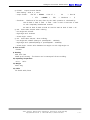
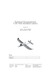
2.1. Dimensions
fig2.1 MSENS-IN360 Dimensions
2.2. Technical specifications
1) Measuring Range
- RS-485 out : 0 ~ 360도 Full-Range
2) Core sensor & CPU
3 axis 1g accelerometer
32bit ARM micro processer
3) Power
Typical : 12Vdc
The sensor was unregulated power(10~30Vdc) supply is also available.
4) Current
<150mA at 12Vdc
5) Resolution
0.1 Degree
6) Max total error
0.25%(FS)
7) Output
309-3, Yangno-ri, Bibong-myeon, Hwaseong-si, Gyeonggi-do, Korea [445-842]
http://www.das-co.com
T) +82-31-356-3541, F) +82-31-356-3572
- 1 -
360degree Inclinometer MSENS-IN360
① RS-485 :
User's Manual
Output Interval 50mSec
- Serial Setting : 9600, 8, 1, none
- output format :
Hex 02
=
- Checksum :
+ 359.90
STX
+ Hex 17
+ ANGLE +
+
ETB
06
+
+
Hex 24
Checksum +
$
Checksum of the way down by the 'XOR' operation is calculated by.
Hex 02 XOR ‘3’ XOR ‘5’ XOR ‘9’ XOR ‘.’ XOR ‘9’ XOR ‘9’ XOR Hex 17 XOR
Or with completely hexadecimal notation:
02 XOR 33 XOR 35 XOR 39 XOR 2C XOR 39 XOR 39 XOR 17 XOR = 06
② mA : Users select mA/mV when ordering
- Low-angle end: 4.32mA
- High-angle end: 19.68mA
- Center-angle : 12mA
③ mV : Users select mA/mV
when ordering
- Low-angle end: 100mV (Change is possible(100 ~ 1000mV))
- High-angle end: 4,900mV(Change is possible(4,000 ~ 4900mV))
- Center-angle : Center value between Low-angle out with High-angle out
8) Turn-on Time
<50mSec
9) Housing
IP66, PVC Case
Water-proof Housing : The Sensor can be waterproof silicone molding.
10) Operating Temperature
-20 to .. +85°C
11) Weight
about 68g
12) Cable
5P Shield cable, 50cm
309-3, Yangno-ri, Bibong-myeon, Hwaseong-si, Gyeonggi-do, Korea [445-842]
http://www.das-co.com
T) +82-31-356-3541, F) +82-31-356-3572
- 2 -
360degree Inclinometer MSENS-IN360
User's Manual
3. Wiring
MSESE-IN360 for a five-stranded shielded cable is used. Supply voltage 2-line, RS-485 2-line,
mA output consists of a line. RS-485 and the unused line of mA output does not touch the
other by cutting the cable must be insulated. When using RS-485 distance is longer than 50M
120 Ohm termination is recommended. In addition, if multiple sensors connected in parallel to
use in the termination resistors.
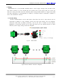
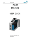
3.1. RS-485 Wiring
RS-485 communications can be read sensor value when the one or more sensors can be
connected in parallel to a line. However, caution this time, each sensor's ID to be different,
continuous data read (# READ) instruction, such as ID and to answer all the sensors,
regardless of instruction should not be used. And when you use multiple sensors to allow
sufficient power supply wiring should be designed.
fig 3.1
Cable Index
fig3.2 RS-485 Parallel connection diagram
309-3, Yangno-ri, Bibong-myeon, Hwaseong-si, Gyeonggi-do, Korea [445-842]
http://www.das-co.com
T) +82-31-356-3541, F) +82-31-356-3572
- 3 -
360degree Inclinometer MSENS-IN360
User's Manual
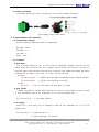
3.2. Analog mA Wiring
The analog output mA output. The 485 can not be like a parallel connection.
fig3.3 Analog output Cable index
4. Communications and command
4.1. Communication Settings
Set the following values 485 need to communicate.
Baudrate : 9600
Data Bits : 8
Stop Bits : 1
Parity : none
4.2. Command
1) Data Read
First of all the transfer of 'CR / LF' will be sent by appending. Reading instruction for the
sensor values are two kinds. The first '# READ' and the second one 'B0 05' is the first to
send the ASCII code, the second will be sent to the hex code. Where 'B0' means the sensor
ID. Sensor ID is '0 xB0 'in the '0 xFF ' is to be a total of 80 dogs.
(1) ASCII
ex) #READ+CR+LF
=> Sensors will send data continuously.(Output Interval 50mSec)
ex) #DATA+CR+LF
=> Sensors will send data to a week.
(2) HEX
ex) B0 05
=> ID is 0, the sensor will send data to a week.
2) Stop transfer
'# READ' command to transfer data continuously. If you stop the transfer of data '# STOP'
to send commands. After all the commands 'CR / LF' will be prefixed with.
ex) #STOP+CR+LF
=> Stop data transfer
3) ID Setting
Sensor ID is '# ID {NO}' can be changed to. After all the commands 'CR / LF' will be
prefixed with.
ex) #ID1+CR+LF => Sensor ID set to 1
=> Return message : #OK+CR+LF
309-3, Yangno-ri, Bibong-myeon, Hwaseong-si, Gyeonggi-do, Korea [445-842]
http://www.das-co.com
T) +82-31-356-3541, F) +82-31-356-3572
- 4 -
360degree Inclinometer MSENS-IN360
User's Manual
ex) B1 05 => Sensor value of sensor 1 ID0 transmission (transmission as a hex code)
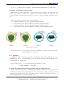
4) Direction and positioning sensors installed
M360 install the sensor according to the position of the direction and angle, you can
specify
the
detection
method.
For
example,
the
sensor
attached
to
the
wall
and
counter-clockwise rotation angle of 0-360 if you want to output, '# MODE' command can be
set.
MODE Set the value according to the value defined
0
=> Sensors installed in the wall, increasing clockwise rotation
1 => The bottom of the sensor installation, increasing clockwise rotation
2
=> Sensors installed in the wall, increasing counter-clockwise rotation
3
=> The bottom of the sensor installation, increasing counter-clockwise rotation
MODE0
MODE2
MODE1
MODE3
fig4.1 Sensor Direction
ex)#MODE1+CR+LF => The bottom of the sensor installation, increasing clockwise rotation
=> Return message : #OK+CR+LF
5) 0 ° positioning
0 degrees is used to specify the location. For example, if the current angle of -10.5 to 0
degrees if you want it, use this feature. At this point, enter the input value multiplied by 10,
you must enter an integer only.
ex)#OFFS-105+CR+LF => 0 to move back as the position of -10.5.
=> Return message : #OK+CR+LF
6) Specify the analog output of measured angular range (For professional use.)
Analog output (mA) and 4.32 ~ 19.68mA output stage is shown. At this point you want
to measure only the desired angle range, the user can specify a range of settings with the
command. For example, when -30〬 to +30〬 then output is 4.32mA to 19.68mA. At the end of
all the commands 'CR / LF' will be prefixed with.
309-3, Yangno-ri, Bibong-myeon, Hwaseong-si, Gyeonggi-do, Korea [445-842]
http://www.das-co.com
T) +82-31-356-3541, F) +82-31-356-3572
- 5 -
360degree Inclinometer MSENS-IN360
User's Manual
CALI Set the value according to the value defined
C => Specify the lower angle range (example. -30 degrees)
D => Specify the Higher angle range (example. -30 degrees)
ex)#CALIC-30+CR+LF => Measured from -30 degrees (4.32mA)
#CALID30+CR+LF
=> Measuring up to 30 degrees (19.68mA)
If the above settings, the analog output -30 to 30 degrees and 4.32 ~ 19.68mA output is
detected. -180 to -30 degree and 4.32mA out, and from +30 to +180 degree 19.68mA
output.
7) Get sensor information
The set of sensor information and can determine the version of sensor.
ex) #INFO+CR+LF => Sensor information transfer
=> Return message : MSENS-IN360 Ver:1.00,ID:B0,MODE...........
8) Initialization (For professional use.)
To reset all settings. Set the value used for calibration, the sensor will reset all features,
including directions. After initializing the use must be recalibrated.
ex) #INIT+CR+LF => Sensor Resetting all settings (factory settings will erase all kinds.)
=> return message : #OK+CR+LF
309-3, Yangno-ri, Bibong-myeon, Hwaseong-si, Gyeonggi-do, Korea [445-842]
http://www.das-co.com
T) +82-31-356-3541, F) +82-31-356-3572
- 6 -
360degree Inclinometer MSENS-IN360
User's Manual
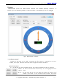
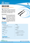
5. Software
MSENS-IN360 provide the 'M360 Display' software. This software operating condition
is
Window O/S. The software operates to check the status of the sensors, ID can be changed.
fig5.1 M360 Display Software
5.1. Software manual
Software is very easy to use. After connecting the first sensor is connected to the port
number, 'Port Open' and then send the sensor triggers the Send Command.
1) Send Command
4 to the left of the Send Command button. This simple command is easy to transport.
'# READ': the sensor will send data continuously. The round gauges and the
angle is shown.
‘B1 05' : On the right side 'ID No' box reads the number of sensors. And
located in the center of the command 'Send Counter' and sends
309-3, Yangno-ri, Bibong-myeon, Hwaseong-si, Gyeonggi-do, Korea [445-842]
http://www.das-co.com
T) +82-31-356-3541, F) +82-31-356-3572
- 7 -
360degree Inclinometer MSENS-IN360
User's Manual
repeated. Sending interval (in msec) and 'Interval' field to enter.
‘#DATA’ : Regardless of the sensor ID and a time to measure the slope.
And located in the center of the command 'Send Counter' and
sends repeated. Sending interval (in msec) and 'Interval' field to
enter.
‘#STOP' : Data transfer stops.
‘B1 05', '#DATA' Will be used to send commands over
and over.
'Send counter' means the number of transfers to the
instruction, 'Interval (> 200)' means the transmission time
interval.
'ID No' to specify a sensor ID number. Enter the number after the 'ID
Change' button will change the sensor ID. The left of the 'B1 05' button,
the sensor ID here to see the ID number is transmitted.
For example, ID number, type 3 and 'B1 05' button to actually send the
hex code to the command 'B3 05' is sent. And the 'INFO' button to bring
up the configuration information of the sensor.
309-3, Yangno-ri, Bibong-myeon, Hwaseong-si, Gyeonggi-do, Korea [445-842]
http://www.das-co.com
T) +82-31-356-3541, F) +82-31-356-3572
- 8 -


![2010 [FACILITATOR]](http://vs1.manualzilla.com/store/data/005655528_1-cab0d059d42c2f5dfa4b2de0f050c49f-150x150.png)