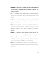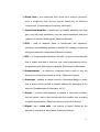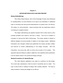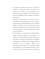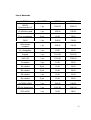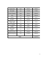
1
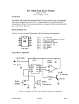
Library Noise Detector and Short
Information Provider
By
Caryll S. Ferrer
Harvey L. Lim
Aubrey Rae P. Ronquillo
A Design Report Submitted to the School of Electrical Engineering,
Electronics and Communications Engineering, and Computer
Engineering in Partial Fulfilment of the Requirements for the Degree
Bachelor of Science in Computer Engineering
Mapúa Institute of Technology
November 2008
ii
ACKNOWLEDGEMENT
We, the designers, would like to thank our parents for the support that they
have given us in building the design that we have made; our friends who
willingly participated in testing our design effectively; Engr. Eliseo R. Francisco
who has been patient in giving us lectures and recommendations in the making
of the design; Prof. Benigno Agapito Jr. who checked the format of our
document; Prof. Susana Alabastro who patiently proof read our documents; and
especially God Almighty, who gave us strength and patience in making our
design and documenting our sources.
Caryll S. Ferrer
Harvey L. Lim
Aubrey Rae P. Ronquillo
iii
TABLE OF CONTENTS
TITLE PAGE
i
APPROVAL SHEET
ii
ACKNOWLEDGEMENT
iii
TABLE OF CONTENTS
iv
LIST OF TABLES
vi
LIST OF FIGURES
vii
ABSTRACT
viii
Chapter 1: DESIGN BAKCGORUND AND INTRODUCTION
1
The Design setting or context or frame of reference
Statement of the Problem
The Objective of the Design
The Significance of the Design
The Conceptual Framework
The Scope and Delimitation
Definition of Terms
Chapter 2: REVIEW OF RELATED LITERATURE AND RELATED STUDIES
Noise Detection: Bandwidth Uncertainty
and Adjustable Channels
Room Noise Detector
Snore Alarm Electronic Device
Noise Sensor Simplifies Automated Noise Monitoring
WHO Standard Environmental Noise
Decibel Loudness Chart
Chapter 3: Design Methodology and Procedures
Design Methodology
Design Procedures for Actual Design
Hardware Design
1. Block Diagram
2. Schematic Diagram
1
4
4
5
6
7
8
13
13
14
15
18
19
19
23
23
23
26
26
27
iv
3. List of Materials
Hardware Components
Software Design
Software Components
Prototype Development
Chapter 4: TESTING, PRESENTATION, AND INTERPRETATION OF DATA
Testing of the Operation of the Library Noise Detector
with Short Message Provider
Testing of the Operation of Noise Detector
Quantifying the Noise in the Circuit
Testing of Noise Detection with Different Source of Sound
Testing of Noise Detection with Varying Distances
Chapter 5: CONCLUSION AND RECOMMENDATIONS
Conclusion
Recommendation
34
35
30
38
40
42
42
42
43
44
46
49
49
50
BIBLIOGRAPHY
51
Appendix A Material Listings and Price Lists
Appendix B Data Sheets
Appendix C Program Listing
Appendix D User’s Manual
53
54
59
83
v
LIST OF TABLES
Table 2.1: World Health Organization suggested
Environmental Noise Level.
Table 2.2: Environmental Noise
Table 2.3: OSHA Daily Permissible Noise Level Exposure
Table 2.4: Perceptions of Increases in Decibel Level
Table 2.5: Sound Levels of Music
Table 3.1: List of Materials
Table 4.1: Testing of the Operation of Noise Detector
Table 4.2: How the noise is quantified in the circuit
Table 4.3: Noise Detection with Different Sound Sources
Table 4.4: Testing Operation with sound level meter
19
19
20
21
22
34
42
43
45
47
vi
LIST OF FIGURES
Figure
Figure
Figure
Figure
Figure
Figure
Figure
Figure
Figure
Figure
Figure
Figure
Figure
Figure
Figure
1.1:
2.1:
2.2:
2.3:
3.1:
3.2:
3.3:
3.4:
Conceptual Framework
Circuit diagram of room noise detector.
Snore Alarm Electronics Device
Schematic Diagram of Snore Alarm Electronic Device
Block Diagram
Diagram of whole library noise detector
Diagram with Microcontroller Z86733
Schematic Diagram of Microcontroller
PIC16F877 for the 8x8 LED Matrix
3.5: Diagram of the Noise Detector
3.6: Schematic Diagram of Power Supply
3.7: PCB Layout for Noise Detector
3.8: PCB Layout for PIC16F877 Microcontroller
3.9: PCB Layout for Z86E08 Microcontroller
3.10: System Flowchart
6.0: Picture of the actual Library Noise Detector
With short Information provider
6
14
15
17
26
29
30
31
32
33
35
35
36
39
85
vii
ABSTRACT
The Library Noise Detector with Short Information Provider is a portable device
that is used in detecting noise in the library. The device is used to control
excessive noise inside the library. The system uses an operational amplifier as a
sensor to detect noise and microcontroller in displaying the output in the
message display. The design was developed as an alternative or additional help
in controlling the noise and prevent disturbances in a specific area of the library.
Keywords: library, sensor, noise, noise detector, microcontroller, operational
amplifier, message display
viii
Chapter 1
DESIGN BACKGROUND AND INTRODUCTION
a. The design setting or context or frame of reference
Noise is widely known in science and technology. Its general meaning in
such fields, as in everyday life, is useless or interfering signal of some form. It is
any unwanted sound due to a variety of causes.
Often, noise is a nuisance
because it interferes with a measurement that it is being made or with some
signal that is being transmitted. The amount of signal, divided by the amount of
noise that is also present, is often called ‘signal – to – noise ratio’. Techniques
such as electronic filtering are often used to improve the signal – to – noise ratio.
This is useful if the signal that is being looked for is at particular frequency; the
filter allows that frequency to pass through, but not the other frequencies which
are present in the noise.
The study of noise is important, because by
understanding the processes that cause it we can try to reduce it. Judgments of
whether or not environmental sounds are noises are subjective, but the fact is
that unwanted sounds can precipitate severe psychological effects. In addition,
above certain levels of intensity, noises can cause physical harm.
Such uses of the term noise have been extended to the fields of electricity
and electronics and, in general, to all areas that involve some form of frequency
range.
Noise is generated within electron tubes and electrical conductors in
general, and all circuits posses an inherent level of random noise.
External
interferences also contribute to electrical and electronic noise.
1
Broadly speaking, the term noise is used in information theory to refer to
any form of disturbance of information-bearing signals, or to any meaningless
addition to such signals.
This does not, however, include redundant signals
added as means of checking the accuracy of the signals.
Noise levels are usually measured in decibel unit. A decibel is one tenth
of a bel (B). Devised by engineers of the Bell Telephone Laboratory to quantify
the reduction in audio level over a 1 mile (1.6 km) length of standard telephone
cable, the bel was originally called the transmission unit or TU, but was renamed
in 1923 or 1924 in honor of the laboratory's founder and telecommunications
pioneer Alexander Graham Bell.
In many situations, however, the bel proved
inconveniently large, so the decibel has become more common.
The decibel (dB) is a logarithmic unit of measurement that expresses the
magnitude of a physical quantity relative to a specified or implied reference level.
Its logarithmic nature allows very large or very small ratios to be represented by
a convenient number, in a similar manner to scientific notation. Being essentially
a ratio, it is a dimensionless unit.
Decibels are useful for a wide variety of
measurements in acoustics, physics, electronics and other disciplines.
The
decibel is not an SI unit, although the International Committee for Weights and
Measures (CIPM) has recommended its inclusion in the SI system. Following the
SI convention, the d is lowercase, as it represents the SI prefix deci-, and the B
is capitalized, as it is an abbreviation of a name-derived unit, the bel (see below).
The full name decibel follows the usual English capitalization rules for a common
2
noun. The decibel symbol is often qualified with a suffix, which indicates which
reference quantity has been assumed. For example, "dBm" indicates that the
reference quantity is one milliwatt.
Noise is always present everywhere but
prohibited to areas that needs to have a peaceful environment such as libraries.
Library is a study place for people especially for students. It is a place
where books, journals, compact discs, microforms, other media, and online
access systems connect searchers to cultural, factual, educational, and
recreational information. This information may be found in the local library or at
other sites in an expanding global network of bibliographic databases. Public
libraries provide access to materials of general interest and are open to
everyone. School libraries support student research and enrich curriculum by
integrating cultural and educational resources into classroom instruction.
Corporate libraries provide businesses with access to current research and
developments in their fields and sustain productivity and competitiveness. In the
mid 1990’s, there were approximately 76,500 school, 15,200 public, 6,000
corporate, 4,600 college and university, and 4,100 law, medical, and religious
libraries in the United States, and Mexico. These range in size from the Library
of Congress to the smallest elementary school library.
libraries serving the media and professions.
In addition, there are
American libraries currently are
expanding and enriching their services in an economy dominated by converging,
computing, and communication technologies while facing severe cutbacks in
public funding and government support.
3
A quiet ambiance is essential in the library; it should have a peaceful and
noiseless environment all the time to avoid distractions to library users.
But
most of the time, as the people in the library increase; noise is always present
and cannot be easily managed by the library staffs. With this implication, the
groups decided to design a system that can help detect noise in the library with
an alert message provider to let the people become aware whenever they are
making loud noises.
The device will monitor the library without further
intervention of the library staffs.
b. Statement of the Problem
Generally, the library is a learning place for everyone. In places like this
where people are always present the tendency of having noise cannot be
avoided. When library becomes a noisy environment the main library rule to
observe silence is violated. As the people in library increase, there is a bigger
probability to have uncontrollable noise inside the library.
In this case, the
library staffs have a hard time controlling and informing the people that they are
creating intolerable noise that can disturb others.
c. Objective of the Design
The design aims to create a device that will detect excessive noise inside
the library as well as inform the library users of the rules and regulations that are
strictly implemented.
The following points were considered in order to implement the design
project:
4
1. To be able to lessen the library staff’s task in maintaining a quiet
ambience;
2. To interface noise detector circuit with a microcontroller-based
message display; and
3. To design an effective and efficient device for the use of school
libraries.
d. The Significance of the Design.
The design provides the library staff with a means of immediately
controlling the noise level inside the library with any arrangement of the people.
It further provides a means of instructing students to accept responsibility for
maintaining a level of noise in to the library conducive to studying. The message
provider presents a good alternative in posting or displaying the library rules and
regulations.
For the designers being also student is and having the right to use the
library, it is important for them to implement the design to help the library staff
in managing and making the library a better learning place. All the people using
the library will benefit from the design especially when they are annoyed of the
noise and distractions created by unconcerned people.
5
e. Conceptual Framework
In order to build the design, Ideas and principles related to the design
were studied and discussed. Figure 1.1 shows the conceptualized design of the
system.
This conceptual framework illustrates how the system of the design
works starting from its inputs then how it will be processed until it produces an
output.
INPUT
Noise
User
setting
OUTPUT
PROCESS
-Detect the noise
within the area
-Communicates within
the microcontrollers
-Provides the alert
messages for awareness
-A chime sound from a
wireless alarm after
a noise is detected
-A short message to alert
that silence should be
observed (LED Matrix)
Figure 1.1 Conceptual Frame work
The inputs are the noise and the user settings which are independent
variables that come from the user and the surroundings. The noise is the main
input for the design that needs to be detected. The noise level that the detector
should identify can be varied through a potentiometer.
After the noise is
detected, the two microcontrollers will act as the communication medium for the
detector and the output devices. The Z86733 microcontroller will process the
signal that the detector sends and then pass the alert message made or chosen
by the user to the PIC16F877 microcontroller for it to output in the 8x8 LED
Matrix. A chime sound will first occur after the detected noise is processed and
6
then followed by a short alert message. This concept describes how the device
was designed for its environment and its users.
f. Scope and Delimitation
The device covers and delimits the following:
Scope
1. The noise level that the detector should detect can be varied
through a potentiometer.
2. LCD display is used to see the saved messages or user input
message.
The keypad can be used to input lowercase and
uppercase letters and numbers as well or a combination of different
format of characters.
3. The LED matrix is used for message display.
4. Select button and delete button are provided.
5. A chime sound will occur once a noise is detected and the selected
message will appear.
6. It automatically returns to a monitoring mode with a default
message upon completion of its response mode.
7. The device is a stand alone; it does not need a computer or other
devices to change message and do other things.
8. It will use the principle of noise detector.
7
Delimitation
1. The detection of noise may be delayed considering the distance
and the volume of noise from the microphone.
2. The message length can reach up to 35 characters only.
3. The standby mode has a default message that cannot be changed
by the user.
4. There are only limited numbers of messages to choose from the
design project.
5. The different messages to choose from are installed in the
microcontroller which is limited to four different rules and
regulations of a library.
6. User input message should be placed before the noise detector
detects a noise.
7. The scrolling messages experience delay because it also considers
the blank spaces as a character.
g. Definition of Terms
These are the technical terms which are mentioned in the design
documentation and design as follows:
1. Alarm – a device that signals the occurrence of some undesirable
event (Electronics for the Electrician).
8
2. Analog – implies a continuous signal in contrast with digital, which
breaks everything into numbers (Instruments and Measurements for
Electronics).
3. Assembly - translation of computer language; the translation of
assembly language
into
machine language
(IBM
PC
Assembly
Language).
4. Breadboard – a thin plastic board used to held electronic components
that are wired together (Electronic Devices).
5. Decibel – literally means one tenth of a bel. A unit named after
Alexander Graham Bell. It is not an absolute unit but rather it is
indicated
the
relation
between
two
powers
(Communications
Engineering, Black Book).
6. Detector – a device that recovers information of interest contained in
a modulated wave (Electronic Sensors for the Evil Genius).
7. Device – an invention serving a particular purpose, especially a
machine used to perform one or more relatively simple tasks
(Instruments and Measurement for Electronics).
8. Electret Microphone – a type of condenser microphone which
eliminates the need for a power by using permanently-charged material
(Electronic Sensors for the Evil Genius).
9
9. Frequency – the number of complete cycles per second in alternating
current direction. The standard unit of frequency is the hertz (Hz)
(Electronic Devices).
10. IC – or “Integrated Circuit”; a tiny complex of electronic components
contained on a thin chip or wafer of semiconducting material (Digital
Design).
11. Keypad - a set of buttons arranged in a block which usually bear digits
and other symbols but not a complete set of alphabetical letters
(Electronics for Electrician).
12. LED - light-emitting diode; a semiconductor diode that emits light when
conducting current and is used in electronic equipment, esp. for
displaying readings on digital watches, calculators, etc. (Electronic
Devices).
13. Library - a collection of books, newspapers, records, tapes, or other
materials that are valuable for research (The World Book Dictionary).
14. Microcontroller - a single chip that contains the processor, nonvolatile memory for the program, volatile memory for input and output,
a clock and an I/O control unit (Electronics for Electrician).
15. Noise – an unwanted energy, usually of random character, present in
transmission system, due to a variety of causes (Communications Engineering,
Black Book).
10
16. Noise Level – are measured with noise level meters, generally
with a weighting that mirrors human sensitivity to different
frequencies (Communications Engineering, Black Book).
17. Operational Amplifier – special type of amplifier exhibiting very high
gain, very high input impedance, very low output impedance, and good
rejection of common diode signals (Electronic Devices).
18. PCB – used as dielectric fluids in transformers and capacitors,
lubricants, and stabilizing additives in flexible PVC coatings of electrical
wiring and electronic components (Electronic Devices).
19. PIC – or “Programmable Interface Controller”; a type of microcontroller
that is widely used due to their low cost, serial programming and reprogramming with flash memory capability (Electronics for Electrician).
20. Potentiometer – an electronic component that is used to vary the
amount of current flows through a circuit. (Electronic Devices).
21. Prototype - building an actual circuit to a theoretical design to verify
that it works, and to provide a physical platform for debugging it if it
does not (Fundamentals of Electronics, vol.3).
22. Sensor - a device that measures or detects a real-world condition,
such as motion, heat or light and converts the condition into an analog
or digital representation (Electronics Sensors for the Evil Genius).
23. Signal – to – noise ratio - the amount of signal, divided by the
amount of noise that is also present (Electronic Devices).
11
24. Sound – created when objects vibrate, resulting in a minute variation
in surrounding atmospheric pressure (Communications Engineering,
Black Book).
25. Sound Level Meter - measures sound pressure level and are
commonly used in noise pollution studies for the quantification of
almost any noise (Communications Engineering Black Book).
26. Transducer – electronic device that converts energy from one form to
another (Electronic Devices).
27. Zilog – a onetime programmable microcontroller which helped to
create the personal computer industry (Electronics for Electrician).
12
Chapter 2
REVIEW OF RELATED LITERATURE AND RELATED STUDIES
Noise detection: Bandwidth uncertainty and adjustable channels
Previous work has shown that the detection of band-pass noise patterns is
well described by an ideal observer, indicating that observers can integrate
spatial frequency information efficiently over a six-octave wide band (Kersten,
1987). One interpretation of this result is that observers use a channel with an
adjustable bandwidth that matches the bandwidth of the signal when detecting
band-pass noise (Green, 1960).
To investigate the notion that observers use
adjustable bandwidth channels for spatial frequency, we had observers perform a
noise detection task under two conditions: an uncertainty condition where the
bandwidth of the noise could vary from trial to trial and a blocked condition
where the bandwidth of the signal was held constant during a block. We used
horizontal, one-dimensional, band-pass noise patterns that were Gaussian
windowed.
The center-frequency of the noise was 5 cycles/degree and
bandwidth varied from one-half to four octaves. Seven bandwidths were used
and a detection threshold measured at each bandwidth for both the blocked and
uncertainty conditions. Stimuli were presented for 200ms. At each bandwidth,
three 150 trial thresholds were collected.
Noise detection r.m.s. contrast
thresholds increase with the fourth-root of bandwidth for the ideal observer. For
our blocked condition, we again found that human observers’ noise detection
thresholds increase with the fourth-root of bandwidth (Kersten, 1987). Under
13
conditions of bandwidth uncertainty, we found that detection thresholds
continued to increase with the fourth-root of bandwidth. Our results support the
notion that when detecting wide-band noise patterns, observers can adjust the
band of spatial frequencies they use from trial to trial and select the frequency
band efficiently. To explore adjustable channels further, we are investigating the
effects of stimulus duration, center-frequency uncertainty and the combination of
center-frequency and bandwidth uncertainty on noise detection.
Room Noise Detector
Figure 2.1 Shows the circuit of an existing room noise detector Which is
used as the basis of the circuit of the library noise detector. However instead of
using fixed resistors, a variable potentiometer is used for the variation of noise
levels.
Figure 2.1 Circuit diagram of room noise detector.
The 50 db setting is provided to monitor the noise in the bedroom at
night.
If the LED is steady or flashes bright often, then the bedroom is
inadequate and too noisy for sleep. The 70 dB setting is for living rooms. If this
level is often exceeded during the day, the area is uncomfortable. If the noise
14
level is constantly over 85 dB, light 8 hours a day, then the environment is
dangerous.
LM358 IC Dual Operational Amplifier is used to provide necessary circuit
gain for sounds picked-up by a miniature electret microphone to drive a LED.
Voltage gain should be measured in order to quantify if the sound entering the
circuit is considered as noise in the circuit. The same IC is used to make the
design of the project possible.
Snore Alarm Electronic Device
Figure 2.2 Snore Alarm Electronics Device
Figure 2.2 is the picture of the snore alarm electronic device. Breathe is a
repetitive phenomenon.
Moments of silence and noise repeat.
Detection of
snoring is based on the recognition of the cycle silence-snoring. The duration of
each silence is compared to the duration of the previous silence.
1.
The duration of each noise is compared to the duration of the previous
noise. The precision of the periodicity of the cycle as well as the number of
15
successive cycles necessary to trigger the alarm can be configured by the use
of jumpers connected to the input port of a micro controller.
Based on Figure 2.3 the snore alarm electronic device uses two
potentiometers, one to control the sound level of the tweeter and second to
control the final gain of the analog amplifier. When the user wants to increase
the sensitivity, the knob should be turned clockwise and at the middle course, a
long liner airplane at 10000 feet makes enough noise to switch off the LED. On
power up, a timer is reset and starts to count. The device is active only for the
first two hours and after six hours. If the alarm triggers after fourteen hours, it
means that a new night started and the timer is reset. This is to avoid alarms
right in the middle of the night.
This circuit is used to apply potentiometer in the design project.
16
Figure 2.3 Schematic Diagram of Snore Alarm Electronic Device
17
Noise sensor simplifies automated noise monitoring
Based on this research study, the Cirrus Environmental has launched its
MK:427 noise sensor - a self-contained outdoor noise meter that connects
directly to SCADA systems. The sensor allows noise level data to be incorporated
into Process Measurement and Control systems.
The data can be stored to
provide a complete record of a plant's noise activities, and can also be used to
control noisy processes in real time.
For example, a pump or fan can be
throttled back when the noise it generates reaches an excessive level at the site
boundary.
Unlike a conventional sound level meter, the MK: 427 convert the
noise level in decibels into standard 4-20mA and linear DC outputs. With the 420mA output, very long cable lengths can be used without reducing the accuracy
of noise measurements.
The sensor incorporates a 1.2m microphone pole,
allowing the microphone to be positioned in free space, well away from any
obstructions.
Cirrus said that the pure analogue electronics are reliable and operate
without any user intervention.
The sensor hardware is based on a well-
established Cirrus design that has been proven in harsh weather conditions. To
ensure that the sensitive microphone transducer is always in good condition, it is
fitted with an electrostatic actuator calibrator. This can be used to make regular
fixed-point calibrations of the entire measuring chain, thus verifying data
integrity. A pre-scaling calibration system allows any 65dB span in the range 20
to 130dB to be selected by the user.
18
Cirrus Environmental aims to help organizations measure the noise they
make and thereby help manage the impact that noise has on neighbors and the
surrounding environment.
WHO Standard Environmental Noise
The World Health Organization has published guidelines suggesting the
environmental noise lead:
Where?
School playground (outdoors)
Hospital rooms
Classrooms
Libraries
Factories, traffic, shopping areas,
both indoors and outdoors
Why?
Avoid annoyance.
To avoid disturbing sleep.
To ensure that speakers can understand
one another.
To avoid destructions and annoyance to
others.
To avoid hearing impairment.
dB
55
30
35
40
70
Table 2.1 World Health Organization suggested environmental noise level.
The information outlined in Table 2.1 is used as a basis to the setting of
the noise level that the noise detector should detect.
Decibel Loudness Chart
These are the measured increase in decibel level that depends on the
change of the volume of sound.
PERCEPTIONS OF INCREASES IN DECIBEL LEVEL
1 db
Imperceptible change
3 db
Barely perceptible change
5 db
Clearly noticeable change
10 db
About twice as loud
20 db
About four times as loud
Table 2.2 Perceptions of Increases in Decibel Level
19
Based on Table 2.2, the allowable additional amount of decibel level
should only limit with the values given in the table to have an acceptable change
of sound level in the sense of hearing.
These data are collected from a variety of sources which can help one to
understand the volume levels of various sources and how they can affect our
hearing.
DECIBEL
0 db
35 db
60-70 db
80 db
85 db
90 db
95 db
90-95 db
107
100
110
115
db
db
db
db
ENVIRONMENTAL NOISE
EXAMPLE OF SOUND SOURCES
Weakest sound heard
Whisper Quiet library
Normal conversation
Telephone dial tone
City traffic (inside car)
Train whistle at 500’, truck traffic
Subway train at 200’
LEVEL AT WHICH SUSTAINED EXPOSURE MAY RESULT IN
HEARING LOSS
Power mower at 3’
Snowmobile, motorcycle
Power saw at 3’
Sandblasting, loud rock concert
Table 2.3 Environmental noise
Table 2.3 pertains to different environmental noises and their equivalent
noise level measured in decibel.
The Occupational Safety and Health Administration (OSHA) suggested the
following daily permissible noise level exposure.
20
OSHA DAILY PERMISSIBLE NOISE LEVEL EXPOSURE
HOURS PER DAY
SOUND LEVEL
8
90 db
6
92 db
4
95 db
3
97 db
2
100 db
1.5
102 db
1
105 db
.5
110 db
.25 or less
115 db
Table 2.4 OSHA Daily Permissible Noise Level Exposure
Based on Table 2.3, each person can only be exposed to these certain
values of noise level directly proportional to the number of hours per day in
order to avoid hearing impairment.
In an orchestral music room, each musical instrument has its own sound
level of music.
The commonly used musical instruments are listed with their
corresponding sound level in Table 2.5.
The table shows the measurements of sound levels quantify the music
from becoming noise. The sound level may also depend on the kind of music
played by the musicians using these instruments and the volume of the music
created. An excess in the sound level creates noise.
21
SOUND LEVELS OF MUSIC
DECIBEL
SOUND SOURCES
60 – 70 db
Normal piano practice
70 db
Fortissimo singer, 3’
75 – 85 db
Chamber music, small auditorium
84 – 103 db
Piano Fortissimo
82 – 92 db
Violin
85 – 111 db
Cello
95 – 112 db
Oboe
92 – 103 db
Flute
90 – 106 db
Piccolo
85 – 114 db
Clarinet
90 – 106 db
French horn
85 – 114 db
Trombone
106 db
Tympani and bass drum
94 db
Walkman on 5/10
120 – 137 db
Symphonic music peak
120 db
Amplifier rock, 4-6’
150 db
Rock music peak
Table 2.5 Sound Levels of Music
These statistics for the Decibel Chart were taken from a study by Marshall
Chasin, M.Sc., Aud©, FAAA, Centre for Human Performance & Health, Ontario,
Canada. There were some conflicting readings and, in many cases, authors did
not specify at what distance the readings were taken or what the musician was
actually playing. In general, when there are several readings, the higher one is
chosen.
22
Chapter 3
DESIGN METHODOLOGY AND PROCEDURES
Design Methodology
The Library Noise Detector with a Short Message Provider was developed
for implementation in school libraries to be used as an alternative or additional
help in controlling noise and prevent disturbances in a specific area of the library.
The design is a microcontroller - based prototype that can stand-alone without
connecting to computer devices.
The design methodology was applied research that is often used to solve
practical problems that relate to this kind of study.
This form of research is
necessary to improve this field of technology. The group research is based on
different designs of previous studies in relation to the design project. Additional
information and concepts needed were gathered from books, journals, articles,
and internet for further understanding of the design concepts.
With this
information, the group was able to portray the process of the system.
This
approach helps the design to obtain a balance to the objectives and expectations
from the actual results of the produced design prototype.
Design Procedures for Actual Design
The noise detector application was used as a reference for the design.
The circuit was customized so that the level of sensitivity can be varied. The
logic of the process in making the design was carefully analyzed. The step by
step processes in making the design are as follows:
23
1. The problem was determined and the factors that should be
considered in the design were identified.
The objectives of the
design were set and ideas on how the prototype should be
designed were gathered. Adaptation to the environment where the
design will be implemented was also considered for the quality of
the design itself.
2. Researches on related literature for the design and how to
conceptualize the other related designs were done. Deciding on
the approach and the possible applications that can be coordinated
altogether for the design were one of the tasks was to find the
suitable microcontrollers that can be used and tested using analog
input from a serial data. These researches helped how the design
should be implemented.
3. The circuit diagram of the noise detector was developed with the
application of operational amplifier and a potentiometer for the
variation of the noise level and the analog output needed by the
microcontroller. The designed circuit was tested in the breadboard
and during testing - the blinking of the LED indicator dictates the
characteristic
of
the
noise
detection.
Z86733,
a
Zilog
Microcontroller was used in the process of connecting the Keypad
inputs, displaying it to the LCD and sending the data to the other
microcontroller. Each pin of this microcontroller was manipulated
24
how it will function and be connected to other devices.
It also
stored the program of the process and how the alarm can be
manipulated according to its assigned function in the design. The
Z86733 Microcontroller is also the communication medium for the
PIC16F77, the microcontroller which connected the noise detector
and the 8x8 LED Matrix.
4. Program listing was the next process after designing the circuit
diagrams. The program applied the assembly language. A serial
input of data was used to test the program to the design itself.
Each function in the program was separated according to the
objectives of the alert message displayed and the operation of the
other devices connected to the microcontroller. The LCD was the
output device for all the inputs in the keypad.
The behavior of
each button in the keypad was also included in the program listing
including each delays and functions on interchanging characters in
the keypad, which is similar to the characteristic of a cellular phone
keypad. Additional buttons were also included in the design for
editing the alert message and for choosing the library rules and
regulations that would be saved inside the microcontroller.
The
stand-by message was also included in the program while the
device is in the steady state.
25
5. After being tested, the circuit was transferred into a PCB layout to
avoid loose circuitry as compare to the breadboard. The program
was also burned in the ICs of the microcontrollers for further
testing of the whole design prototype.
Testing and experiments
have been made to test if the program works according to its
environment on a near and far range of noise. The testing and
interpretation of data will be further discussed in the next chapter.
Hardware Design
The following diagram refers to the hardware design of the system:
1. Block Diagram
LCD
2x40 characters
Alarm
Microcontroller
Z86733
Keypad
PIC16F877
Noise Detector
Microcontroller of the
LED Matrix
8x8 LED Matrix
Figure 3.1 System Design Block Diagram
26
Figure 3.1 shows an illustration of the System Block Diagram for the
system design. Initially, the user will set the desired noise level in the noise
detector and an alert message to be displayed after detection.
By using the
keypad, the user can input alert messages which are temporarily shown in the
LCD display. When the noise signal is detected and exceeds the noise level set,
the PIC16F877 microcontroller is triggered.
After the PIC microcontroller
receives the signal, it will transfer to the Z86733 microcontroller and the alarm
will be turned on. The Z86733 will acknowledge the transferred signal and it will
then pass the user input message to PIC16F877 that controls the 8x8 LED Matrix
for message display.
2. Schematic Diagram
The schematic diagram of the design system illustrates how the circuitry
of the design was developed and connected with each other.
Figure 3.2 shows the whole circuit of the Library Noise Detector with Short
Information Provider.
This schematic diagram describes the different
components used for the whole design system. This circuit operates as noise
sensor and message provider that are put together as one design system. The
block
diagram represents
the
other
circuit
connected to
the
Z86733
microcontroller. For the schematic diagram of the power supply, refer to Figure
3.6.
Figure 3.3 refers to the schematic diagram of the Z86733 microcontroller.
This microcontroller is responsible for handling the data to be displayed in the
27
LCD display and LED matrix. The seven pins of the keypad for the row and
column are connected to the input ports of the Z86733. The input/output ports
of the LCD display are connected to the Z86733 for displaying the data. The
alarm switch is also connected to P01 of the microcontroller.
Figure 3.4 is the schematic diagram of the 8 x 8 LED Matrix display. The
LED Matrix display is connected to PIC16F877 as driver to display the message.
The PIC is connected to the noise detector and the Z86733 microcontroller.
Once the noise is detected, it will trigger the PIC to display the message.
Figure 3.5 refers to the circuit of the noise detector. The noise detector
uses LM358 IC which is a dual operation amplifier. The electret microphone is
connected to the input part of the circuit. The circuit has a connection to the
input of the PIC16F877 and connected to Z876733 to trigger the alarm and the
message display once noise is detected.
28
Figure 3.2 Schematic Diagram of the whole Library Noise Detector with Short Information
Provider
29
Figure 3.3 Schematic Diagram with Microcontroller Z86733
30
10.240 MHz
Figure 3.4 Schematic Diagram of Microcontroller PIC16F877 for the 8x8 LED Matrix
31
Figure 3.5 Schematic Diagram of the Noise Detector
32
Figure 3.6 Schematic Diagram for the Power Supply
33
3. List of Materials
The following is the list of materials used in creating the circuit of the
design system:
Materials
Quantity
Materials
Quantity
Z86733 Microcontroller IC
1 pc
03SBA10 bridge rectifier
diode
1 pc
10.240Mhz crystal
1 pc
2200 uf/35v capacitor
1 pc
27 pf np capacitor
2 pcs
0.1 uf capacitor
4 pcs
78L05
1 pc
2n3904
8 pcs
Male-female connector
1 pc
Toggle switch
2 pcs
0.1 uf capacitor
1 pc
Tact switch
1 pc
Keypad
1 pc
14”x18” Plywood
2 pcs
2x40 LCD
1 pc
PCB
1 pc
1k resistor
3 pc
8x8 LED Matrix
2 set
10k resistor
6 pcs
Wireless doorbell
1 pc
56k resistor
3 pcs
Electret Microphone
1 pc
33k resistor
1 pc
1N4001
2 pcs
22k resistor
2 pcs
PIC16f877
1 pc
1 pc
Lm7805/Lm7808
2 pc
LM358 Dual Operational
Amplifier
750 mA transformer
1 pc
2200 uf/25v
1 pc
Table 3.1. List of Materials
34
Hardware Components
These figures show the actual PCB layouts of the hardware components in
the circuit.
PCB Layouts
Figure 3.7 Noise Detector
Figure 3.7 shows the PCB layout of the circuit of noise detector. It is a
double sided etched with single wired PCB design.
35
Figure 3.8 Z86733 Microcontroller
Figure 3.8 shows the PCB layout for the Z86733 Microcontroller.
The
layout shows how the other components such as resistors, transistors, and
capacitors should be connected to the pin configuration of the IC.
Figure 3.9 PIC16F877 Microcontroller
Figure 3.9 illustrates the actual PCB layout of the PIC16F877. This lay-out
shows the connection on the IC of the PIC microcontroller of the crystal,
capacitor, and voltage regulators as part of the hardware components.
LCD Display
The saved and input messages are displayed in the LCD. The data to be
displayed will come from the microcontroller. The LCD will display the options of
the user and the selected alert messages will be displayed in the LED Matrix.
36
Keypad
A keypad that operates like a cellular phone keypad was used for the user
input message.
8 x 8 LED Matrix
Since the design displayed short information, an 8x8 LED Matrix was used
to display information visible to the people inside the library. It is displayed the
selected message of the user once noise was detected. It also displayed the
default message while in standby mode.
Electret Microphone
The electret microphone serves as a transducer in the circuit. It converts
noise to electrical signal given that the circuit is an electrical circuit. Basically, it
is a cardiod type of microphone which is said to be the most common
unidirectional since all microphones can only absorb when the source is in front.
Operational Amplifier
The operational amplifier has been found to be the best device for the
system design.
microphone.
It is a device that amplifies the signal coming from the
By getting the voltage gain in this stage, the noise can be
quantified in the circuit.
Its unique characteristic helped to make the design
possible.
Software Design
The microcontroller was used for the design project. It gives control to
the operation of the whole system of the design especially in interfacing the
37
noise detector with the LED Matrix display and also with the other input/output
devices used in the circuit.
The microcontrollers save the data coming from the user for message
display. It also functions as a medium for transmitting the noise signal coming
from the noise detector.
The main routine of the program of the
microcontrollers is to save the user input data and to acknowledge the noise
signal being detected.
Software Components
The software component part of the
design is
placed
in the
microcontroller which serves as the storage of the received data as well as the
communication medium between the other parts and i/o devices within the
system design. The language of the program in the Z86733 microcontroller is an
Assembly Language which has simpler and shorter syntax of program codes. For
the PIC16F877 microcontroller, the programming language used was C# for the
LED Matrix display. The program codes are separated according to the different
functions that will be performed by the i/o devices in the system design.
Instruction sets used in the program dictates how each ports in the
microcontrollers should be assigned and how each ports should function either as
a receiver or sender of the data inputs and outputs as well.
38
1. System Flowchart
START
Initialization of LCD
Input data using the
keypad
Short inform ation
to be displayed
NO
Is there a noise?
Continue displaying
the default stand by
m essage
Y ES
Send serial data to
PIC m icrocontroller
Output the short
inform ation from the
Z86733
END
Figure 3.10 System Flowchart
39
Figure 3.10 shows the system flowchart of the design project. The
flowchart specifies how the system decides and sets its condition before it
outputs any results.
It indicates the operation of the microcontrollers in
processing the input data of the user and the input data coming from the noise
detector. The flowchart is the overall route of all the inputs until it produces a
certain output.
Prototype Development
The summary of the whole process of developing the Library Noise
Detector with a Short Message Provider is as follows:
1. Submission and approval of the proposed design project
2. Conducting research on related studies, articles and literature about the
system design.
2.1
Existing circuit of noise sensors as basis.
2.2
The applicable or suitable microcontroller to be used.
2.3
The standard noise level for the environment of the library
where the design should be implemented.
2.4
The program language to be used for the i/o device.
3. Preparing the list of materials and electronic devices to be used for the
design hardware.
40
4. Designing the circuitry of the noise detector with a variation of noise
level.
5. Testing the circuitry and encoding the program listing for the message
display
6. Modifying and testing the actual finish product of the design in an
environment for demonstration purposes.
41
Chapter 4
TESTING, PRESENTATION, AND INTERPRETATION OF DATA
Since the design of the noise detector was based on an existing room
noise detector as discussed in Chapter 2 of the Review of Related Literature and
Related Studies, the circuit was redesigned by having a potentiometer instead of
fixed values of resistances and several switches for setting the noise level to be
detected. After the device has been constructed, several testing has been made
on the prototype and the operation of each major components of the system. In
testing the operation of the detection process, it is essential to know if the
program responds with the electronic devices. Hence, checking was made by
data validity and setting of the noise level of the noise detector.
Testing of the Operation of Noise Detector
In conducting the test, the circuit of the noise detector and the source of
sound are needed. The initial testing made was checking if the existing room
noise detector with a fixed noise level will work after replacing it with a
potentiometer with variable resistances. The noise detector circuit was formed
and temporarily tested in a bread board with a LED indicator for the noise
detection.
After the circuit was formed, it was placed in a slightly noisy
environment. In this testing the exact noise level was not yet exactly measured.
KNOB POSITION OF
THE POTENTIOMETER
Approx. 50 dB
Approx. 65 dB
Approx. 85 dB
STATUS OF THE LED
CONDITION
Lights on and continuously blinking
Lights on and blinking
Lights on
Very good
Good
Slight delay of detection
Table 4.1 Testing of the Operation of the Noise Detector
42
The result of this test showed the behavior of the noise detector as it
detected noise or different sources of sounds from its environment. Since the
noise level did not measure the threshold value of the resistance set for 50 db to
85 db, noise level the position of the knob showed how the noise level varied.
The KNOB POSITION OF THE POTENTIOMETER became the comparative
medium in determining the validity of the data in noise detection. Moreover, the
STATUS OF THE LED can be determined when the LED lighted on as the noise
detector detected noise. The CONDITION results indicated that the tests simply
show that the noise detector is in good condition and that it can determine the
validity of an input noise.
Quantifying the Noise in the Circuit
In order to quantify the considerable noise in the library based on the
circuit of the noise detector, another test was made which showed how the noise
level was set and how much voltage was needed to reach a certain noise level.
To conduct the test, a digital multimeter and the noise detector circuit were
used.
The reference AC voltage as well as the variable resistances in the
potentiometer was measured. The noise level depended on the voltage gain of
the operational amplifier.
VOLTAGE
RESISTANCE
9.49 V
30 V
94.87 V
533.48 V
50 Ω
12.5 K Ω
25 K Ω
51.4 K Ω
DECIBEL
50
60
70
80
db
db
db
db
CONDITION
Noise
Noise
Noise
Noise
detected
detected
detected
detected
Table 4.2 How the noise is quantified in the circuit
43
Based on Table 4.2, the resistances in potentiometer are set and the
output voltage is measured. The reference is a quiet environment in the library
having a 0.03 AC voltage. The table shows the values of the output voltages
that should be produced by the circuit in order to obtain the set noise level and
trigger the message display. In order to compute the equivalent decibel value,
the gain was computed based on the formula of db = 20 log (Vout / Vin). When
the input noise reaches these certain amount of voltages, it is considered noise
in the circuit. The standard noise levels can be found based on Chapter 2 on
Review of Related Literature and Related Studies. The results of this test help
the user to understand how the noise is quantified by the noise detector
considering different kinds of sources from the environment.
Testing of Noise Detection with Different Source of Sound
To perform the test, the noise detector circuit and any sound source were
needed. After learning how the noise level was set and varied from the results
of its detection, another testing was done in a 7.4’ x 6.3’ x 8.1’ room to show
and test how the noise detector detects different sources of noise that are
usually found in a library.
In the test conducted, specific sound sources
commonly heard in a school library were used. The Noise Detector was set to 50
db, 65 db, 85 db to detect noise based on the LED indicator and if the
PIC16F877 was triggered to display an alert message. The status results are
most likely expected to have similar results based on the earlier test done by the
noise detector.
44
At 50 db noise level
TEST
1
SOURCE OF
SOUND
STATUS OF THE LED
REMARKS
Blinking with high intensity of LED
Message displayed
Continuous blinking of LED
Message displayed
Blinking with high intensity of LED
Message displayed
Blinking with Low intensity of LED
Message displayed
Steady with High intensity of LED
Message displayed
Steady with High intensity of LED
At 65 db noise level
Message displayed
5
Whistle
Clapping
Normal
Conversation
Blowing of horns
(outside the room)
Music
6
Scream
TEST
SOURCE OF
SOUND
STATUS OF THE LED
REMARKS
1
Whistle
Blinking with low intensity
No message
displayed
2
Clapping
Continuous blinking with low intensity of
LED
Message displayed
Blinking with low intensity of LED
Message displayed
2
3
4
3
4
Normal
Conversation
Blowing of horns
(outside the room)
No detection
5
Music
Steady with low intensity of light
6
Scream
Steady with low intensity of LED
TEST
SOURCE OF
SOUND
STATUS OF THE LED
1
Whistle
Low detection, low intensity of LED
2
Clapping
No detection
No message
displayed
No message
displayed
No message
displayed
At 85 db noise level
3
4
Normal
Conversation
Blowing of horns
(outside the room)
5
Music
6
Scream
No detection
No detection
Steady light and dependent on the volume
of sound.
Blinking with low intensity of LED
REMARKS
No message
displayed
No message
displayed
No message
displayed
No message
displayed
Message displayed
Message displayed
Table 4.3 Noise Detection with Different Sound Sources
Table 4.3 shows the different results in testing the library noise detector
with different sources of sound. Based on the results, the noise detector can
45
easily detect constant noise and high pitch sounds. The detection varies with the
kind of sound produced and its distance to the noise detector. The sensitivity of
the sensor depends on the noise level set on the noise detector. If the noise
level is low, the detector can easily detect noise and if the noise level is high,
longer time is needed to detect noise. The intensity of light of the LED indicates
how much noise is detected. When the intensity of light of the LED is high it
means that the noise has reached the sound level set on the noise detector. If
the LED blinks the noise is detected and it can either produce an alarm or not. If
it does not produce an alarm but the LED is blinking, it means that the noise
detector can still detect but the noise does not reach the sound level set on the
noise detector.
On the remarks, messages saved from the Z86733
microcontroller are transferred to the PIC16F877 for message display in the 8x8
LED Matrix. These messages are only displayed if the noise detector has enough
voltage gain to trigger the microcontroller.
Sudden loud noise that occurred during testing such as sneezing,
whistling, and banging of the door was easily detected.
Testing of Noise Detection with Varying Distances
The following materials were used to conduct the test: sound level meter,
push-pull rule, and the noise detector circuit.
The noise detector was set to approximately 50 db noise level and in a
testing room that measured 31’ x 23.5’ x 18.95’. The setting was only at the
minimum noise level of 50 db because according to the researches, 40 db is the
46
considerable noise level in a library environment. Since the device was placed on
each table inside the library, the distance of the source of sound is 0.25m, 0.5m,
and 1m measured by the push-pull rule from the noise detector. This testing
aimed to prove that the noise detector can detect different sound sources even if
the source was almost one meter away from the noise detector. The sound level
meter was used to measure the amount of noise in terms of decibel.
Sound Level
Meter
Normal Conversation
Source
Distance
Trial 1
0.25 m
55dB
Trial 2
0.50 m
48 dB
Trial 3
1m
40 dB
Remarks
Noise detected with message
display
Noise detected but with no
message display
Noise detected but with no
message display
Music
Trial 1
0.25 m
55 dB
Trial 2
0.50
45 dB
Trial 3
1m
40 dB
Noise detected with message
display
Noise detected but with no
message display
Noise detected but with no
message display
Scream
Trial 1
0.25 m
58 dB
Trial 2
0.50 m
51 dB
Trial 3
1m
45 dB
Noise detected with message
display
Noise detected with message
display
Noise detected but with no
message display
Table 4.4 Testing Operation with Sound Level Meter
Based on the results in Table 4.4 the measured values have discrepancy
due to the consistency of the sound sources that the sound level meter detects.
The noise level of the sound varies with its distance to the sound level meter.
When the source is near the sound level meter, the decibel value is higher and
as it gets farther, the decibel value decreases. For this reason, the detection of
47
the noise detector also depends on the distance of the sound source. As the
sound level meter measures the noise level, the noise detector also detects the
noise at the same time. It shows that the noise level set in the potentiometer is
only approximately 50 db since lower than 50 db is still detected by the noise
detector.
The remarks prove the design project set the validity of the input
noise. It only triggers the PIC16F877 to send alert messages to be displayed in
the 8x8 LED Matrix if it reaches the set noise level of 50 db.
Even though
detection of noise is in the process in the noise detector, the warning is only
made if the source of noise will reach or exceed 50 db which proves the
efficiency and quality of the noise detector and the microcontrollers for the
message display as the design projects works altogether.
48
Chapter 5
CONCLUSION AND RECOMMENDATION
Conclusion
The design project was able to detect excessive noise and provide a short
message to remind the library users not to make excessive noise. This feature of
the design is an aid to avoid having too much noise created by the people inside
the library.
The library staff takes care of borrowed and returned books as well as
maintaining order in the library. The device will inform the library users through
the detector’s alarm and alert messages displayed on a LED matrix panel after
detection of excessive noise; thus lessening the library staff’s task of maintaining
a quiet ambience.
Based on the research conducted, a noise detector was designed that can
vary the noise level, and through microcontrollers, a message display device was
used to add functions to the whole design system. The Library Noise Detector
with Message Provider was put into operation by interfacing a noise detector’s
circuit into a microcontroller based 8x8 LED Matrix.
Most of the time, students go to the library just to hangout, chat with
friends or use for their benefit of the facilities without realizing the disturbances
they create. This design project will be very much effective in maintaining order
in school libraries because it will make the students become aware of the proper
manner inside the library.
49
Recommendation
A further enhancement on the design of the Library Noise Detector with
Short Message Provider is recommended in terms of its capacity for detection of
other kinds of noise sources and its message provider. Making the design not
just portable but also wireless would be a great improvement of the design itself.
A Wireless FM Transmitter and Receiver can be used in order to transmit the
input signals from the microphone to the system design. This device is also used
to create a wireless connection from the noise detector to the message display
device. This is implemented to provide convenience and allows the library staff
or roaming security guard to control the device at a distance of 10 meters
maximum. For practicality means it is much better to have only one set of the
Library Noise Detector provided that it can detect noise in a larger area and alert
messages are displayed in larger panel of LED Matrix.
The design system can also be applied in classrooms, offices and in any
environment where silence needs to be observed. More improvement can be
applied in the packaging of the whole system design, to have a more
sophisticated look in putting altogether all the parts or input/output devices of
the design prototype.
50
BIBLIOGRAPHY
Bogart T., Linear Electronics (1993); Rutkowski, G., Operational Amplifiers,
Detection of Signals in Noise.2nd Edition (March 1993); Robert McDonough, Noise
Level
Fay, Thomas H., ed., Noise and Health (1991); Morrison, Ralph, Noise and Other
Integrated and Hybrid Circuits (1993); Stanley, W., Operational Amplifiers with
Linear Integrated Circuits, 3d ed., (1993)
Interfering Signals (1991); Tempest, W., ed., The Noise Handbook (1985).
Kingfisher Science Encyclopedia. Noise. Vol.7 p.491
Taylor, C.P., Bennett, P.J., & Sekuler, A.B. (2003), Noise detection: bandwidth
uncertainty and adjustable channels [Abstract]. Journal of Vision, 3(9): 9a.
World Book Dictionary, Volume 1 (A-K) and Volume 2 (L-Z) © 1976, By Field
Enterprises Educational Corporation All rights reserved.
Birgitta Berglund, Thomas Lindvall and Dietrich H. Schwein, editors. Guidelines
for Community Noise. World Health Organization, 1999.
Floyd, Thomas L. Electronic Devices, 5th Edition, p.842 – p.867
Mano, Morris,. Digital Design, 3rd edition
Herrick, Clyde N., Instruments and Measurement for Electronics, p.17 – p.19
Petruzzelis, Tom, Electronic Sensors for the Evil Genius, p.3 – p.15
Owen, George E., Keaton, P.W., Fundamentals of Electronics, Vol.3
Braga, Newton C., Electronics for the Electrician
51
APPENDIX A
Material Listings and Price Lists
52
List of Materials
MATERIALS
QUANTITY
PRICE
TOTAL
Z86733
Microcontroller IC
1 pc
P200.75
P200.75
10.240Mhz crystal
1 pc
P35.00
P35.00
27 pf np capacitor
2 pcs
P2.50
P5.00
78L05
1 pc
P18.00
P18.00
Male-female
connector
1 pc
P25.00
P25.00
0.1 uf capacitor
1 pc
P2.50
P2.50
Keypad
1 pc
P113.00
P113.00
2x40 LCD
1 pc
P700.00
P700.00
1k resistor
3 pc
P1.00
P3.00
10k resistor
6 pcs
P1.00
P4.00
56k resistor
3 pcs
P1.00
P3.00
33k resistor
1 pc
P1.00
P1.00
22k resistor
2 pcs
P1.00
P2.00
Lm7805/Lm7808
2 pc
P24.00
P48.00
750 mA transformer
1 pc
P187.00
P187.00
2200 uf/25v
1 pc
P8.00
P8.00
53
Toggle switch
2 pcs
P10.00
P20.00
Tact switch
1 pc
P 18.00
P 18.00
14”x18” Plywood
2 pcs
P75.00
P150.00
PCB
1 pc
P160.00
P160.00
1N4001
2 pcs
P2.00
P4.00
PIC16f877
1 pc
P225.00
P225.00
03SBA10 bridge
rectifier diode
1 pc
P35.00
P35.00
0.1 uf capacitor
4 pcs
P2.50
P10.00
2n3904
8 pcs
P5.00
P40.00
2200 uf/35v
capacitor
1 pc
P12.00
P12.00
Wireless doorbell
1 pc
P499.95
P499.95
Electret Microphone
1 pc
P 150.00
P150.00
Total
P 4,952.20
54
APPENDIX B
Data sheets
55
56
ZILOG Z86733 MICROCONTROLLER
57
58
59
APPENDIX C
Program Listing
60
Program Listing in the Z86733 for Keypad and LCD
data_set1
data_set2
data_out
position
milli
press_no
counter
letra
variable1
variable2
value
ctr
bitrate
com_flag
shift_bit
seconds
indicator
.equ 20h
.equ 21h
.equ 22h
.equ 23h
.equ 24h
.equ 25h
.equ 26h
.equ 27h
.equ 28h
.equ r10
.equ r11
.equ r12
.equ r13
.equ r14
.equ r15
.equ 6ch
.equ 6dh
;lcd
;3sec delay
;keypad
.org 00h
.word 0ffffh ;p33
.word 0ffffh ;p32
.word 0ffffh ;p31
.word 0ffffh ;p30
.word baudrate
.word timer_int
.org 0ch
di
srp #10h
ld spl,#80h
ld p01m,#04h
ld p2m,#00110000b
ld p3m,#01h
;disable interrupt
;set register pointer to #10h
;initialized stack pointer at 80h
;set port0( p0 )as output
;set port2 (p2 )as output
;set port2 as digit and push-pull mode
clr irq
clr ipr
ld t1,#3bh
ld pre1,#00010011b
ld pre0,#00100101b ;104 micro secs.
ld t0,#15
;note set crystal oscillator 11.150mhz; 15 use 10.24mhz
ld imr,#30h
ei
;enable interrupt
61
call erase_ram
ld r4,#29h
ld 28h,#0ffh
clr p3
clr p0
call delay2
call lcd_init
restart:
ld r6,#>tittle
ld r7,#<tittle
call line1
ld r6,#>school
ld r7,#<school
call line2
call delay2
call line2
ld position,#0c3h
ld r6,#>clear
ld r7,#<clear
call line1
ld r6,#>clear
ld r7,#<clear
call line2
jr input
; starting position of char display in the lcd
loop_restart:
tm p3,#01h
jr z,loop_restart
ld r6,#>clear
ld r7,#<clear
call line2
call delay
input:
ld r6,#>lower
ld r7,#<lower
call line1
call delay
call keypad
input_a:
cp press_no,#02h
jp eq,keyabc
cp press_no,#03h
jp eq,keydef
cp press_no,#04h
62
jp eq,keyghi
cp press_no,#05h
jp eq,keyjkl
cp press_no,#06h
jp eq,keymno
cp press_no,#07h
jp eq,keyprs
cp press_no,#08h
jp eq,keytuv
cp press_no,#09h
jp eq,keywxy
cp press_no,#00h
jp eq,keyzero
cp press_no,#0f3h
jr eq,upper_input
jr input
upper_input:
ld r6,#>upper
ld r7,#<upper
call line1
call delay
call keypad
upper_a:
cp press_no,#02h
jp eq,keyABC
cp press_no,#03h
jp eq,keyDEF
cp press_no,#04h
jp eq,keyGHI
cp press_no,#05h
jp eq,keyJKL
cp press_no,#06h
jp eq,keyMNO
cp press_no,#07h
jp eq,keyPRS
cp press_no,#08h
jp eq,keyTUV
cp press_no,#09h
jp eq,keyWXY
cp press_no,#00h
jp eq,keyZERO
cp press_no,#0f3h
jp eq,numlock
jr upper_input
63
numlock:
ld r6,#>number
ld r7,#<number
call line1
call delay
or tmr,#0ch
numlock_a:
call keypad
cp press_no,#01h
jr eq,key1
cp press_no,#02h
jp eq,key2
cp press_no,#03h
jp eq,key3
cp press_no,#04h
jp eq,key4
cp press_no,#05h
jp eq,key5
cp press_no,#06h
jp eq,key6
cp press_no,#07h
jp eq,key7
cp press_no,#08h
jp eq,key8
cp press_no,#09h
jp eq,key9
cp press_no,#00h
jp eq,key0
cp press_no,#0f3h
jp eq,input
jr numlock_a
readytosend:
ld r1,#29h
ld r0,#'A'
call tx_data
ld r0,#'T'
call tx_data
ld r0,#'+'
call tx_data
send_msg:
ld r0,@r1
call tx_data
inc r1
cp r1,#6ah
;transfer the content data of address to working reg r0
;pulse enable
64
jr eq,return1
jr send_msg
;inc address to fetch next character from ascii
return1:
ld r0,#0h
call tx_data
ld p0,#06h
call delay2
ld p0,#0h
; this is for the alarm on state
; alarm off state
hang:
tm p2,#20h
jr nz,readytosendb
jr hang
readytosendb:
tm p2,#20h
jr nz,readytosendb
jr readytosend
;========= numlock text =========
key1:
ld letra,#02h
ld variable1,#'1'
ld variable2,#02h
call showtxt
jp numlock_a
key2:
ld letra,#02h
ld variable1,#'2'
ld variable2,#02h
call showtxt
jp numlock_a
key3:
ld letra,#02h
ld variable1,#'3'
ld variable2,#02h
call showtxt
jp numlock_a
key4:
ld letra,#02h
ld variable1,#'4'
ld variable2,#02h
call showtxt
jp numlock_a
key5:
ld letra,#02h
65
ld variable1,#'5'
ld variable2,#02h
call showtxt
jp numlock_a
key6:
ld letra,#02h
ld variable1,#'6'
ld variable2,#02h
call showtxt
jp numlock_a
key7:
ld letra,#02h
ld variable1,#'7'
ld variable2,#02h
call showtxt
jp numlock_a
key8:
ld letra,#02h
ld variable1,#'8'
ld variable2,#02h
call showtxt
jp numlock_a
key9:
ld letra,#02h
ld variable1,#'9'
ld variable2,#02h
call showtxt
jp numlock_a
key0:
ld letra,#02h
ld variable1,#'0'
ld variable2,#02h
call showtxt
jp numlock_a
;=========== keytext =============
keyabc:
ld letra,#04h
ld variable1,#'a'
ld variable2,#02h
call showtxt
jp input_a
keydef:
ld letra,#04h
ld variable1,#'d'
66
ld variable2,#03h
call showtxt
jp input_a
keyghi:
ld letra,#04h
ld variable1,#'g'
ld variable2,#04h
call showtxt
jp input_a
keyjkl:
ld letra,#04h
ld variable1,#'j'
ld variable2,#05h
call showtxt
jp input_a
keymno:
ld letra,#04h
ld variable1,#'m'
ld variable2,#06h
call showtxt
jp input_a
keyprs:
ld letra,#05h
ld variable1,#'p'
ld variable2,#07h
call showtxt
jp input_a
keytuv:
ld letra,#04h
ld variable1,#'t'
ld variable2,#08h
call showtxt
jp input_a
keywxy:
ld letra,#05h
ld variable1,#'w'
ld variable2,#09h
call showtxt
jp input_a
keyzero:
ld letra,#02h
ld variable1,#20h
ld variable2,#00h
call showtxt
jp input_a
keyautospace:
67
ld letra,#02h
ld variable1,#20h
ld variable2,#0ffh
call showtxt
jp input_a
keyABC:
ld letra,#04h
ld variable1,#'A'
ld variable2,#02h
call showtxt
jp upper_a
keyDEF:
ld letra,#04h
ld variable1,#'D'
ld variable2,#03h
call showtxt
jp upper_a
keyGHI:
ld letra,#04h
ld variable1,#'G'
ld variable2,#04h
call showtxt
jp upper_a
keyJKL:
ld letra,#04h
ld variable1,#'J'
ld variable2,#05h
call showtxt
jp upper_a
keyMNO:
ld letra,#04h
ld variable1,#'M'
ld variable2,#06h
call showtxt
jp upper_a
keyPRS:
ld letra,#05h
ld variable1,#'P'
ld variable2,#07h
call showtxt
jp upper_a
keyTUV:
ld letra,#04h
ld variable1,#'T'
ld variable2,#08h
68
call showtxt
jp upper_a
keyWXY:
ld letra,#05h
ld variable1,#'W'
ld variable2,#09h
call showtxt
jp upper_a
keyZERO:
ld letra,#02h
ld variable1,#20h
ld variable2,#00h
call showtxt
jp upper_a
keyAUTOSPACE:
ld letra,#02h
ld variable1,#20h
ld variable2,#0ffh
call showtxt
jp upper_a
;======== keypad routine========
keypad:
clr seconds
keypad_a:
jp delete_button
loop_keypad:
cp seconds,#18
; timer for auto increment
jp uge,keypad_out
and p0,#00000000b
or p0,#01110000b
tm p3,#02h
jr nz,two
call delayk
ld press_no,#01h
ret
two:
tm p3,#04h
jr nz,three
call delayk
ld press_no,#02h
ret
three:
tm p3,#08h
jr nz,four
call delayk
69
ld press_no,#03h
ret
four:
call wait_1
and p0,#00000000b
or p0,#10110000b
tm p3,#02h
jr nz,five
call delayk
ld press_no,#04h
ret
five:
tm p3,#04h
jr nz,six
call delayk
ld press_no,#05h
ret
six:
tm p3,#08h
jr nz,seven
call delayk
ld press_no,#06h
ret
seven:
call wait_1
and p0,#00000000b
or p0,#11010000b
tm p3,#02h
jr nz,eight
call delayk
ld press_no,#07h
ret
eight:
tm p3,#04h
jr nz,nine
call delayk
ld press_no,#08h
ret
nine:
tm p3,#08h
jr nz,ask
call delayk
ld press_no,#09h
ret
ask:
call wait_1
70
and p0,#00000000b
or p0,#11100000b
tm p3,#02h
jr nz,zero
call delayk
ld press_no,#'*'
sub press_no,#30h
ret
zero:
tm p3,#04h
jr nz,sharp
call delayk
ld press_no,#0h
ret
sharp:
tm p3,#08h
jp nz,keypad_a
call delayk
ld press_no,#'#'
sub press_no,#30h
ret
keypad_out:
ld press_no,#0ffh
ret
delete_button:
tm p2,#10h
jr z,erase_char
tm p2,#20h
jp nz,readytosend
tm p3,#01h
jp z,message_one
jp loop_keypad
erase_char:
clr seconds
looperase_char:
cp seconds,#20
jr ule,looperase_char
cp position,#0c3h
jr eq,exit_erase
dec position
dec r4
loop_erase:
cp seconds,#30
; timer for erasing all char
jr uge,erase_lahat
tm p2,#10h
jr z,loop_erase
71
ld data_out,#20h
call dis_char
ld press_no,#0edh
ret
; flag for erasing a char
exit_erase:
ld position,#0c3h
ret
erase_lahat:
ld r0,#00
ld r1,#29h
clean:
ld @r1,r0
inc r1
cp r1,#069h
jr ne,clean
ld position,#0c3h
ld r4,#29h
ld r6,#>clear
ld r7,#<clear
call line2
ret
;=================================
showtxt:
or tmr,#0ch
clr counter
ld value,variable1
showtxt1:
call lcddisplay
inc counter
cp counter,letra
jr uge,showtxt
call keypad
cp press_no,#0edh
jr eq,exittext
cp press_no,#0d0h
jr eq,exittext
cp press_no,variable2
jr ne,outshowtx
inc value
clr seconds
jr showtxt1
outshowtx:
cp position,#0e5h
jr eq,stoptxt
cp press_no,#0ffh
72
jr eq,autospace
cp indicator,#0ffh ; autospace flag
jr eq,stoptxt
inc position
inc r4
exittext:
ret
stoptxt:
clr indicator
ret
autospace:
inc position
inc r4
ld indicator,#0ffh ; the autospace happens
ret
lcddisplay:
ld @r4,value
ld data_out,value
call dis_char
ret
;========== transmit routine=========
tx_data:
rcf
or p0,#01h
clr ctr
clr bitrate
and com_flag,#11111110b ;clr rx_flag
or tmr,#03h
idle:
or p0,#01h
;idle
cp bitrate,#1
jr ne,idle
rl r0
rl r0
start_bit:
and p0,#0feh
;start bit
cp bitrate,#2
jr ne,start_bit
or p0,shift_bit
;8 bit data shift
clr ctr
rcf
ld shift_bit,r0
and shift_bit,#01h
loop_upto8:
or p0,shift_bit
; data shift
cp ctr,#8
73
jr ult,loop_upto8
and tmr,#0fch
or p0,#01h
ret
baudrate:
rr r0
ld shift_bit,r0
and shift_bit,#01h
and p0,#0feh
inc ctr
inc bitrate
iret
;========== LCD routine============
display:
add data_out,#30h
dis_char:
ld data_set1,position
call pulse
ld r8,data_out
call pulse1
ret
display_back:
add data_out,#30h
dis_char1:
ld data_set1,position
call pulse
ld r8,data_out
call pulse1
dec position
ret
line1:
ld data_set1,#80h
call pulse
call display_msg
ret
;set first address of first line
;pulse register select
;go to fetching of data from ascii setting
;return
line2:
ld data_set1,#0c0h
call pulse
call display_msg
ret
display_msg:
ldc r8,@RR6 ;transfer the content data of address to working reg r8
cp r8,#24h
74
jp eq,return
call pulse1
;pulse enable
incw RR6
;inc address to fetch next character from ascii
djnz r9,display_msg ;dec working reg. r9 and check if 0, end of line
return:
ld r9,#40
clr r8
ret
;reset the character counter
lcd_init:
ld data_set1,#02h
call pulse
ld data_set1,#28h
call pulse
ld data_set1,#28h
call pulse
ld data_set1,#28h
call pulse
ld data_set1,#0ch
call pulse
ld data_set1,#06h
call pulse
ld data_set1,#01h
call pulse
ld data_set1,#02h
call pulse
ld data_set1,#40h
call pulse
ld data_set1,#80h
call pulse
call delay
ld r9,#40
ret
;set data length for 8 bits/5x7 dots/2line
;pulse enable pin
;entry mode:inc address ,no shift
;pulse enable pin
;set dd ram
;pulse enable pin
;set dd ram
;pulse enable pin
;set dd ram
;pulse enable pin
;set dd ram
;pulse enable pin
;set dd ram
;pulse enable pin
;set dd ram
;pulse enable pin
;return end of initialization
pulse:
call split_data
and p2,#0f0h
or p2,data_set1
or p2,#80h
and p2,#7fh
and p2,#0f0h
or p2,data_set2
or p2,#80h
and p2,#7fh
and p2,#0f0h
call wait_1
ret
;#20h;set enable pin to high state
;#0dfh ;set it low
;#20h;set enable pin to high state
;#0dfh
;wait awhile
;return
pulse1:
75
ld data_set1,r8
call split_data
and p2,#0f0h
or p2,data_set1
and p2,#03fh
or p2,#40h
nop
nop
nop
or p2,#80h
and p2,#07fh
call wait_1
and p2,#0f0h
or p2,data_set2
and p2,#03fh
or p2,#40h
nop
nop
nop
or p2,#80h
and p2,#07fh
nop
nop
nop
and p2,#03fh
call wait_1
ret
;load data to port 2
;#0cfh
;#10h;set register select high
;#20h;set enable and register select pin high
;#0dfh
;load data to port 2
;#0cfh
;#10h;set register select high
;#20h;set enable and register select pin high
;#0dfh
;#0cfh
;clear both pin
split_data:
ld data_set2,data_set1
swap data_set1
and data_set1,#0fh
and data_set2,#0fh
ret
erase_ram:
ld r0,#00
ld r1,#12h
clean2:
ld @r1,r0
inc r1
cp r1,#07fh
jr ne,clean2
ld r1,#31h
ret
;========== timer interrupt routine ===========
timer_int:
76
inc milli
cp milli,#100
jr uge,segundo
iret
segundo:
clr milli
inc seconds
iret
;======== delay routine =========
wait_1:
ld r3,#1fh
busy:
djnz r3,busy
ret
delay:
ld r3,#01fh
loop1:
ld r2,#0ffh
loop2:
djnz r2,loop2
djnz r3,loop1
ret
delay2:
ld
r0,#100
del:
call delay
dec r0
cp r0,#0
jr ne,del
ret
delayk:
ld r6,p3
rr r6
and r6,#07h
cp r6,#07h
jr ne,delayk
clr p3
call delay
ret
;========== default display for matrix =============
message_one:
tm p3,#01h
jr z,message_one
call erase_lahat
77
;observe_silence:
ld r6,#>message1
ld r7,#<message1
call line1
ld r6,#>observe
ld r7,#<observe
call line2
ld 29h,#'O'
ld 2ah,#'b'
ld 2bh,#'s'
ld 2ch,#'e'
ld 2dh,#'r'
ld 2eh,#'v'
ld 2fh,#'e'
ld 30h,#' '
ld 31h,#'s'
ld 32h,#'i'
ld 33h,#'l'
ld 34h,#'e'
ld 35h,#'n'
ld 36h,#'c'
ld 37h,#'e'
loop_msg1:
tm p2,#20h
jr nz,readytosendmsg1
tm p3,#01h
jr z,message_two
jr loop_msg1
readytosendmsg1:
tm p2,#20h
jr nz,readytosendmsg1
call send_savemessage
jr loop_msg1
message_two:
tm p3,#01h
jr z,message_two
call erase_lahat
ld r6,#>message2
ld r7,#<message2
call line1
ld r6,#>do_not
ld r7,#<do_not
call line2
ld 29h,#' '
ld 2ah,#'D'
78
ld 2bh,#'o'
ld 2ch,#' '
ld 2dh,#'n'
ld 2eh,#'o'
ld 2fh,#'t'
ld 30h,#' '
ld 31h,#'l'
ld 32h,#'e'
ld 33h,#'a'
ld 34h,#'v'
ld 35h,#'e'
ld 36h,#' '
ld 37h,#'t'
ld 38h,#'h'
ld 39h,#'i'
ld 3ah,#'n'
ld 3bh,#'g'
ld 3ch,#'s'
ld 3dh,#' '
ld 3eh,#'u'
ld 3fh,#'n'
ld 40h,#'a'
ld 41h,#'t'
ld 42h,#'t'
ld 43h,#'e'
ld 44h,#'n'
ld 45h,#'d'
ld 46h,#'e'
ld 47h,#'d'
loop_msg2:
tm p2,#20h
jr nz,readytosendmsg2
tm p3,#01h
jr z,message_three
jr loop_msg2
readytosendmsg2:
tm p2,#20h
jr nz,readytosendmsg2
call send_savemessage
jr loop_msg2
message_three:
tm p3,#01h
jr z,message_three
call erase_lahat
ld r6,#>message3
79
ld r7,#<message3
call line1
ld r6,#>sleeping
ld r7,#<sleeping
call line2
;sleeping:
ld 29h,#' '
ld 2ah,#'s'
ld 2bh,#'l'
ld 2ch,#'e'
ld 2dh,#'e'
ld 2eh,#'p'
ld 2fh,#'i'
ld 30h,#'n'
ld 31h,#'g'
ld 32h,#' '
ld 33h,#'a'
ld 34h,#'n'
ld 35h,#'d'
ld 36h,#' '
ld 37h,#'e'
ld 38h,#'a'
ld 39h,#'t'
ld 3ah,#'i'
ld 3bh,#'n'
ld 3ch,#'g'
ld 3dh,#' '
ld 3eh,#'a'
ld 3fh,#'r'
ld 40h,#'e'
ld 41h,#' '
ld 42h,#'n'
ld 43h,#'o'
ld 44h,#'t'
ld 45h,#' '
ld 46h,#'a'
ld 47h,#'l'
ld 46h,#'l'
ld 47h,#'o'
ld 46h,#'w'
ld 47h,#'e'
ld 46h,#'d'
loop_msg3:
tm p2,#20h
jr nz,readytosendmsg3
tm p3,#01h
80
jp z,loop_restart
jr loop_msg3
readytosendmsg3:
tm p2,#20h
jr nz,readytosendmsg3
call send_savemessage
jr loop_msg3
message_four:
tm p3,#01h
jr z,message_three
call erase_lahat
ld r6,#>message4
ld r7,#<message4
call line1
ld r6,#>cellphone
ld r7,#<cellphone
call line2
;cellphone:
ld 29h,#' '
ld 2ah,#'c'
ld 2bh,#'e'
ld 2ch,#'l'
ld 2dh,#'l'
ld 2eh,#'p'
ld 2fh,#'h'
ld 30h,#'o'
ld 31h,#'n'
ld 32h,#'e'
ld 33h,#' '
ld 34h,#'a'
ld 35h,#'r'
ld 36h,#'e'
ld 37h,#' '
ld 38h,#'n'
ld 39h,#'o'
ld 3ah,#'t'
ld 3bh,#' '
ld 3ch,#'a'
ld 3dh,#'l'
ld 3eh,#'l'
ld 3fh,#'o'
ld 40h,#'w'
ld 41h,#'e'
ld 42h,#'d'
81
loop_msg4:
tm p2,#20h
jr nz,readytosendmsg4
tm p3,#01h
jp z,loop_restart
call erase_lahat
jr loop_msg4
readytosendmsg4:
tm p2,#20h
jr nz,readytosendmsg4
call send_savemessage
jr loop_msg4
send_savemessage:
ld r1,#29h
ld r0,#'A'
call tx_data
ld r0,#'T'
call tx_data
ld r0,#'+'
call tx_data
loopsend_msg:
ld r0,@r1
;transfer the content data of address to working reg r0
call tx_data ;pulse enable
inc r1
cp r1,#6ah
jr eq,return1a ;inc address to fetch next character from ascii
jr loopsend_msg
return1a:
ld r0,#0h
call tx_data
ld p0,#06h
; this is for the alarm on state
call delay2
ld p0,#0h
; alarm off state
ret
;======== LCD display =========
clear:
.ascii "
$"
tittle:
.ascii " Microcontroller Based Matrix Display $"
school:
.ascii " Mapua Institute of Technology $"
lower:
.ascii "-->lowercase:
$"
upper:
82
.ascii "-->uppercase:
$"
.ascii "-->num. lock:
$"
number:
message1:
.ascii "-->message one: $"
message2:
.ascii "-->message two: $"
message3:
.ascii "-->message three: $"
observe:
.ascii "Observe Silence$"
do_not:
.ascii "Do not leave your things unattended$"
sleeping:
.ascii "Sleeping and eating are not allowed$"
cellphone:
.ascii "Cellphones are not allowed$"
.end
83
APPENDIX D
User’s Manual
84
Library Noise Detector with Short Information Display
User’s Manual
These are the proper ways in using the designed noise detector:
1. Initially plug on the device in a 220 VAC to turn-on the system design.
Make sure that the toggle switch on the noise detector is turned-off
before any task is be done.
8. To choose whether the message is a user input or a stored message,
press the push button beside the keypad.
when the button is pushed.
A stored message appears
If you want to display a personal input
message to display, wait until a blank selection appears.
9. If it is a user input message, enter the short information that you want to
display during the detection of the noise within the library. Enter alert
messages that can really catch the attention of the library user.
10. The keypad functions like the cellular phone keypad and the tact switch
beside the keypad is used for deleting a character.
11. Set the desired level of sensitivity of the sensor by turning the knob of the
noise detector.
The clockwise direction makes the noise detector turn
from 50 decibel to 80 decibel.
12. Turn on the toggle switch in the noise detector to start the communication
between the display device and the noise detector.
85
13. Leave the device on the table or in a specific place in the library then let it
function by itself.
A default message of “Mapua Library” will be shown
until noise is detected. The chime sound will occur, the LED indicator in
the sensor blinks, and the entered short information will be displayed once
noise is sensed.
Figure 6. Pictures of the actual Library Noise Detector with Short Information
Provider
86