1
NX-900/ NX-901
800MHz DIGITAL TRANSCEIVER
900MHz DIGITAL TRANSCEIVER
INSTRUCTION MANUAL
ÉMETTEUR-RÉCEPTEUR NUMÉRIQUE 800MHz
ÉMETTEUR-RÉCEPTEUR NUMÉRIQUE 900MHz
MODE D’EMPLOI
TRANSCEPTOR DIGITAL 800MHz
TRANSCEPTOR DIGITAL 900MHz
MANUAL DE INSTRUCCIONES
© B62-2384-00 (K)
09 08 07 06 05 04 03 02 01 00
NX-900/NX-901
INSTRUCTION MANUAL
ENGLISH
800MHz DIGITAL TRANSCEIVER
900MHz DIGITAL TRANSCEIVER
THANK YOU
We are grateful you have chosen Kenwood for your personal mobile applications.
We believe this easy-to-use transceiver will provide dependable communications
to keep personnel operating at peak efficiency.
Kenwood transceivers incorporate the latest in advanced technology. As a result,
we feel strongly that you will be pleased with the quality and features of this product.
NOTICES TO THE USER
◆ Government law prohibits the operation of unlicensed transmitters within the territories under
government control.
◆ Illegal operation is punishable by fine and/or imprisonment.
◆ Refer service to qualified technicians only.
SAFETY: It is important that the operator is aware of, and understands, hazards
common to the operation of any transceiver.
◆ EXPLOSIVE ATMOSPHERES (GASES, DUST, FUMES, etc.)
Turn OFF your transceiver while taking on fuel or while parked in gasoline service stations. Do not carry
spare fuel containers in the trunk of your vehicle if your transceiver is mounted in the trunk area.
◆ INJURY FROM RADIO FREQUENCY TRANSMISSIONS
Do not operate your transceiver when somebody is either standing near to or touching the
antenna, to avoid the possibility of radio frequency burns or related physical injury.
◆ DYNAMITE BLASTING CAPS
Operating the transceiver within 500 feet (150 m) of dynamite blasting caps may cause them
to explode. Turn OFF your transceiver when in an area where blasting is in progress, or where
“TURN OFF TWO-WAY RADIO” signs have been posted. If you are transporting blasting caps
in your vehicle, make sure they are carried in a closed metal box with a padded interior. Do not
transmit while the caps are being placed into or removed from the container.
i
One or more of the following statements may be applicable:
FCC WARNING
This equipment generates or uses radio frequency energy. Changes or modifications to this
equipment may cause harmful interference unless the modifications are expressly approved in the
instruction manual. The user could lose the authority to operate this equipment if an unauthorized
change or modification is made.
INFORMATION TO THE DIGITAL DEVICE USER REQUIRED BY THE FCC
This equipment has been tested and found to comply with the limits for a Class B digital device,
pursuant to Part 15 of the FCC Rules. These limits are designed to provide reasonable protection
against harmful interference in a residential installation.
This equipment generates, uses and can generate radio frequency energy and, if not installed and
used in accordance with the instructions, may cause harmful interference to radio communications.
However, there is no guarantee that the interference will not occur in a particular installation. If
this equipment does cause harmful interference to radio or television reception, which can be
determined by turning the equipment off and on, the user is encouraged to try to correct the
interference by one or more of the following measures:
• Reorient or relocate the receiving antenna.
• Increase the separation between the equipment and receiver.
• Connect the equipment to an outlet on a circuit different from that to which the receiver is
connected.
• Consult the dealer for technical assistance.
PRECAUTIONS
Observe the following precautions to prevent fire, personal injury, and transceiver
damage.
• Do not attempt to configure the transceiver while driving; it is too dangerous.
• Do not disassemble or modify the transceiver for any reason.
• Do not expose the transceiver to long periods of direct sunlight, nor place it near heating
appliances.
• If an abnormal odor or smoke is detected coming from the transceiver, switch the
transceiver power off immediately, and contact your Kenwood dealer.
• Use of the transceiver while you are driving may be against traffic laws. Please check
and observe the vehicle regulations in your area.
• Do not use options not specified by Kenwood.
◆ The transceiver operates in 12 V negative ground systems only! Check the battery polarity and
voltage of the vehicle before installing the transceiver.
◆ Use only a Kenwood optional DC power cable.
◆ Do not cut and/or remove the fuse holder on the DC power cable.
For passenger safety, install the transceiver securely using an optional mounting bracket and screw
set so the transceiver will not break loose in the event of a collision.
ii
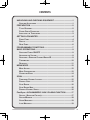
CONTENTS
UNPACKING AND CHECKING EQUIPMENT ....................................1
SUPPLIED ACCESSORIES .......................................................................1
PREPARATION ...................................................................................2
TOOLS REQUIRED ................................................................................2
POWER CABLE CONNECTION .................................................................2
INSTALLING THE TRANSCEIVER ...............................................................3
GETTING ACQUAINTED.....................................................................4
FRONT PANEL .....................................................................................4
DISPLAY .............................................................................................5
REAR PANEL ......................................................................................6
PROGRAMMABLE FUNCTIONS ........................................................7
BASIC OPERATIONS..........................................................................9
SWITCHING POWER ON/OFF ...............................................................9
ADJUSTING THE VOLUME.......................................................................9
SELECTING A ZONE AND CHANNEL/GROUP ID..........................................9
TRANSMITTING ...................................................................................10
RECEIVING ........................................................................................11
MENU MODE .....................................................................................12
MENU ACCESS ..................................................................................12
MENU CONFIGURATION .......................................................................12
CHARACTER ENTRY ...........................................................................14
SCAN .................................................................................................15
TEMPORARY CHANNEL LOCKOUT..........................................................15
PRIORITY SCAN .................................................................................15
SCAN REVERT...................................................................................16
SCAN DELETE/ADD ............................................................................16
PRIORITY-CHANNEL SELECT ................................................................16
FleetSync: ALPHANUMERIC 2-WAY PAGING FUNCTION ............17
SELCALL (SELECTIVE CALLING) ...........................................................17
STATUS MESSAGE .............................................................................18
SHORT MESSAGES .............................................................................19
LONG MESSAGES ..............................................................................19
iii
GPS REPORT...................................................................................19
DTMF (DUAL TONE MULTI FREQUENCY) CALLS........................20
MAKING A DTMF CALL .....................................................................20
AUTODIAL .........................................................................................20
STUN CODE ......................................................................................20
TRUNKING CALLS............................................................................21
MAKING A TELEPHONE CALL ...............................................................21
RECEIVING A TELEPHONE CALL ...........................................................21
EMERGENCY CALLS .......................................................................22
SCRAMBLER.....................................................................................23
SECURE (ENCRYPTED) TRANSMISSION...................................................23
SIGNALING........................................................................................24
QUIET TALK (QT)/ DIGITAL QUIET TALK (DQT) ...................................24
RADIO ACCESS NUMBER (RAN) .........................................................25
OPTIONAL SIGNALING .........................................................................25
ADVANCED OPERATIONS ..............................................................26
CLOCK .............................................................................................26
LCD BRIGHTNESS .............................................................................26
HORN ALERT ....................................................................................26
PUBLIC ADDRESS (PA) ......................................................................27
BACKGROUND OPERATIONS ........................................................28
TIME-OUT TIMER (TOT) .....................................................................28
SIGNAL STRENGTH INDICATOR .............................................................28
COMPANDER .....................................................................................28
BUSY CHANNEL LOCKOUT (BCL) ........................................................29
CONTROL CHANNEL HUNT ..................................................................29
PTT ID ...........................................................................................29
VGS-1 OPTIONAL VOICE GUIDE & STORAGE UNIT .....................30
VOICE RECORDER ..............................................................................30
VOICE GUIDE ....................................................................................31
iv
UNPACKING AND CHECKING EQUIPMENT
Note: The following unpacking instructions are for use by your Kenwood dealer, an authorized
Kenwood service facility, or the factory.
Carefully unpack the transceiver. We recommend that you identify the items
listed in the following table before discarding the packing material. If any items
are missing or have been damaged during shipment, file a claim with the carrier
immediately.
SUPPLIED ACCESSORIES
•
•
•
•
•
•
Microphone (with cable) . . . . . . . . . . . . . . . . . . . . . . . . . . . . . . . . . . . . . . . . .
Microphone hanger (with 4 x 16 mm self-tapping screws) . . . . . . . . . . . . . . .
DC power cable . . . . . . . . . . . . . . . . . . . . . . . . . . . . . . . . . . . . . . . . . . . . . . .
• Fuse (15 A) . . . . . . . . . . . . . . . . . . . . . . . . . . . . . . . . . . . . . . . . . . . . . . . .
Mounting bracket . . . . . . . . . . . . . . . . . . . . . . . . . . . . . . . . . . . . . . . . . . . . . .
Screw set
• 5 x 16 mm self-tapping screw . . . . . . . . . . . . . . . . . . . . . . . . . . . . . . . . . .
• Hex-headed screw with washer . . . . . . . . . . . . . . . . . . . . . . . . . . . . . . . .
• Spring washer . . . . . . . . . . . . . . . . . . . . . . . . . . . . . . . . . . . . . . . . . . . . . .
• Flat washer . . . . . . . . . . . . . . . . . . . . . . . . . . . . . . . . . . . . . . . . . . . . . . . .
Instruction manual . . . . . . . . . . . . . . . . . . . . . . . . . . . . . . . . . . . . . . . . . . . . .
1
1
1
2
1
4
4
4
4
1
1
PREPARATION
Various electronic equipment in your vehicle may malfunction if they are not properly protected
from the radio frequency energy which is present while transmitting. Electronic fuel injection, antiskid braking, and cruise control systems are typical examples of equipment that may malfunction.
If your vehicle contains such equipment, consult the dealer for the make of vehicle and enlist
his/her aid in determining if they will perform normally while transmitting.
Note: The following preparation instructions are for use by your Kenwood dealer, an authorized
Kenwood service facility, or the factory.
TOOLS REQUIRED
Note: Before installing the transceiver, always check how far the mounting screws will extend
below the mounting surface. When drilling mounting holes, be careful not to damage vehicle wiring
or parts.
The following tools are required for installing the transceiver:
• 1/4 inch (6 mm) or larger electric drill
• 5/32 inch (4.2 mm) drill bit for the self-tapping screws used to mount the optional
mounting bracket
• Circle cutters
POWER CABLE CONNECTION
◆ The transceiver operates in 12 V negative ground systems only! Check the battery polarity and
voltage of the vehicle before installing the transceiver.
◆ Use only a Kenwood optional DC power cable.
◆ Do not cut and/or remove the fuse holder on the DC power cable.
1 Check for an existing hole, conveniently located in the firewall, where a power
cable can be passed through. If no hole exists, use a circle cutter to drill the
firewall, then install a rubber grommet.
2 Run the two power cable leads through the firewall and into the engine
compartment, from the passenger compartment.
3 Connect the red lead to the positive (+) battery terminal and the black lead to
the negative (–) battery terminal.
• Locate the fuse as close to the battery as possible.
4 Coil and secure the surplus cable with a retaining band.
• Be sure to leave enough slack in the cables so the transceiver can be removed for
servicing while keeping the power applied.
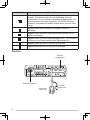
2
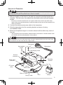
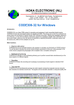
INSTALLING THE TRANSCEIVER
For passenger safety, install the transceiver securely using an optional mounting bracket and screw
set so the transceiver will not break loose in the event of a collision.
1 Mark the position of the holes in the dash by using the mounting bracket as a
template. Drill the holes, then attach the mounting bracket using self-tapping
screws.
• Be sure to mount the transceiver in a location where the controls are within easy
reach of the user and where there is sufficient space at the rear of the transceiver for
cable connections.
2 Connect the antenna and power cable to the transceiver.
3 Slide the transceiver into the mounting bracket and secure it using
hex-headed screws.
4 Mount a microphone hanger in a location where it will be within easy reach of
the user.
• The microphone and microphone cable should be mounted in a location where it will
not interfere with the safe operation of the vehicle.
When replacing the fuse in the DC power cable, be sure to replace it with a fuse of the same value.
Never replace a fuse with a fuse that has a higher value.
Flat washer
Hex-headed
screws
Microphone
Spring washer
Self-tapping screw
Antenna
connector
Mounting
bracket
Power input
connector
DC power
cable
Ignition
sense cable
Black (–) cable
Red (+) cable
Fuse
12 V vehicle
battery
3
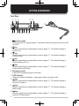
GETTING ACQUAINTED
FRONT PANEL
: @.
;=
B> 2 8 q
(power) switch
Press and hold for approximately 1 second to switch the transceiver power ON
and OFF.
w
key
Press to activate its programmable function {page 7}. The default setting is
Volume Up.
e
key
Press to activate its programmable function {page 7}. The default setting is
Volume Down.
r
key
Press to activate its programmable function {page 7}. The default setting is
Channel/Group ID Up.
t
key
Press to activate its programmable function {page 7}. The default setting is
Channel/Group ID Down.
y Microphone jack
Insert the microphone plug into this jack.
u LED indicator
Lights red while transmitting. Lights green while receiving a call.
i
key
Press to activate its programmable function {page 7}. The default setting is
None (no function).
o
key
Press to activate its programmable function {page 7}. The default setting is
Menu mode.
!0
key
Press to activate its programmable function {page 7}. The default setting is
Squelch Off Momentary.
4
!1
key
Press to activate its programmable function {page 7}. The default setting is
Zone Down.
!2
key
Press to activate its programmable function {page 7}. The default setting is
Zone Up.
!3
key
Press to activate its programmable function {page 7}. The default setting is
None (no function).
!4 Speaker
Internal speaker
!5 PTT (Push-to-Talk) switch
Press and hold this switch then, speak into the microphone to call a station.
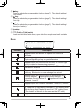
DISPLAY
Indicator
Description
Appears when the Monitor or Squelch Off function is
activated.
Blinks when signaling of an incoming call matches the
Optional Signaling set up on your transceiver.
Appears when the current zone (left icon) or CH/GID (right
icon) is added to the scanning sequence.
Appears when you are using Scan mode. Blinks while
paused at a channel.
Appears when there is a message stored in the transceiver
memory. Blinks when a new message has arrived.
Appears when the current channel is programmed as a
Priority channel. “ ” represents Priority channel 1. “ ”
represents Priority channel 2. “ ” represents Priority
channels 1 and 2.
Appears when the Operator Selectable Tone (OST) function
is activated.
A Telephone ID call is being received in LTR Trunking mode.
Blinks during AutoTelephone search in LTR Trunking mode.
(The location of this icon is the same as the OST icon.)
Appears when the Talk Around function is activated.
5
Indicator
Description
The number of bars indicates the strength of incoming
signals. The antennal plus 3 bars represents a strong
signal while only the antenna represents a weak signal. No
antenna means no signal is present. On NXDN Trunking
channels, the antenna indicator flashes when you are out of
range.
Appears when the Scrambler/ Encryption function is
activated.
Appears when the Auto Recording function on the VGS-1
option is activated.
Appears when the Auto Reply Message is on. (The location
of this icon is the same as the Auto Recording icon.)
Appears when the AUX A function is activated.
Appears when the AUX B function is activated.
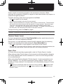
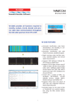
REAR PANEL
External
speaker jack
Antenna connector
Power input
connector
6
Ignition
sense line
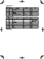
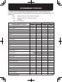
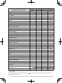
PROGRAMMABLE FUNCTIONS
Following is a list of available programmable functions. Please contact your
dealer for further details on those functions which have been programmed on your
transceiver.
Conv:
Trunk:
✓:
N/A:
Channels set up for Conventional Operation
Channels set up for Trunking Operation
Available
Not Available
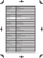
Programmable Function
Auto Reply Message 1
Analog
Conv LTR Trunk
NXDN (Digital)
Conv
Trunk
✓
✓
✓
✓
N/A
✓
N/A
N/A
Autodial
✓
✓
✓
✓
Autodial Programming
✓
✓
✓
✓
AUX A
✓
✓
✓
✓
AUX B
✓
✓
✓
✓
Broadcast
N/A
N/A
N/A
✓
Call 1 ~ 6
✓
✓
✓
✓
CH/GID Down
✓
✓
✓
✓
Channel Entry
✓
✓
✓
✓
CH/GID Up
✓
✓
✓
✓
CH/GID Recall
✓
✓
✓
✓
Clock
✓
✓
✓
✓
Clock Adjustment
✓
✓
✓
✓
N/A
Auto Telephone
N/A
N/A
✓
Direct CH/GID 1 ~ 5
✓
✓
✓
✓
Direct CH/GID Select 1 ~ 5
✓
✓
✓
✓
Display Format
✓
✓
✓
✓
Emergency 2
✓
✓
✓
✓
Fixed Volume
✓
✓
✓
✓
Forced Search
CW Message
N/A
N/A
N/A
✓
Function
✓
✓
✓
✓
GPS Position Display
✓
✓
✓
✓
Group (NXDN)
N/A
N/A
✓
N/A
Group + SDM (NXDN)
N/A
N/A
✓
✓
N/A
N/A
✓
✓
Home CH/GID
✓
✓
✓
✓
Home CH/GID Select
✓
✓
✓
✓
Horn Alert
✓
✓
✓
✓
Individual (NXDN)
N/A
N/A
✓
✓
Individual + SDM (NXDN)
N/A
N/A
✓
✓
Group + Status (NXDN)
7
Programmable Function
Individual + Status (NXDN)
Analog
Conv LTR Trunk
NXDN (Digital)
Conv
Trunk
N/A
N/A
✓
✓
LCD Brightness
✓
✓
✓
✓
Lone Worker
✓
✓
✓
✓
Maintenance
✓
✓
✓
✓
Menu
✓
✓
✓
✓
Monitor
✓
✓
✓
N/A
Monitor Momentary
✓
✓
✓
N/A
OST (Operator Selectable Tone)
✓
N/A
N/A
N/A
Playback 1
✓
✓
✓
✓
Priority-channel Select
✓
N/A
✓
N/A
Public Address
✓
✓
✓
✓
Scan
✓
✓
✓
✓
Scan Delete/Add
✓
✓
✓
✓
Scrambler/Encryption
✓
✓
✓
✓
Scrambler/Encryption Code
✓
✓
✓
✓
SDM (FleetSync/ NXDN)
✓
✓
✓
✓
Selcall (FleetSync)
✓
✓
N/A
N/A
Selcall + SDM (FleetSync)
✓
✓
N/A
N/A
Selcall + Status (FleetSync)
✓
✓
N/A
N/A
✓
✓
✓
✓
Site Lock
N/A
N/A
N/A
✓
Site Up
N/A
N/A
N/A
✓
Site Down
N/A
N/A
N/A
✓
N/A
Send the GPS data
Squelch Level
✓
N/A
N/A
Squelch Off
✓
N/A
N/A
N/A
Squelch Off Momentary
✓
N/A
N/A
N/A
Stack
✓
✓
✓
✓
Status (FleetSync/ NXDN)
✓
✓
✓
✓
✓
✓
✓
N/A
Telephone Disconnect
Talk Around
N/A
✓
N/A
N/A
Transceiver Password
✓
✓
✓
✓
Voice Memo 1
✓
✓
✓
✓
Volume Down
✓
✓
✓
✓
Volume Up
✓
✓
✓
✓
Zone Delete/Add
✓
✓
✓
✓
Zone Down
✓
✓
✓
✓
Zone Up
✓
✓
✓
✓
1
2
8
Auto Reply Message, Playback, and Voice Memo are available only if the VGS-1 optional board has
been installed.
Emergency can be programmed only on the
key and an optional auxiliary switch, such as an
emergency foot switch.
BASIC OPERATIONS
SWITCHING POWER ON/OFF
Press and hold the
switch for approximately 1 second to turn the transceiver
switch again to turn the transceiver OFF.
power ON. Press and hold the
■ Transceiver Password
If the transceiver is password protected, “PASSWORD” will appear on the
display when the power is turned ON. To unlock the transceiver, enter the
correct password:
1 Select a character using the
and
keys.
• If you are using a microphone keypad, you can enter the password by direclty
pressing the DTMF keys instead.
2 Press the
key to enter the selected character.
• This step is unnecessary when using a keypad.
3 Repeat steps 1 and 2 to enter the entire password.
• Press the
key or microphone # key to delete an incorrectly entered character.
Press and hold the
key or microphone # key to delete all characters.
4 Press the
key or microphone
key to confirm the entry.
• If you enter an incorrect password, an error tone sounds and the transceiver
remains locked.
• The password can contain a maximum of 6 digits.
ADJUSTING THE VOLUME
Press the keys programmed with Volume Up/ Volume Down to adjust the
volume level.
SELECTING A ZONE AND CHANNEL/GROUP ID
Select the desired zone using the keys programmed as Zone Up/ Zone Down.
Each zone contains a group of channels.
Select the desired channel/group ID using the keys programmed as CH/GID Up /
CH/GID Down. Each channel/group ID is programmed with settings for
transmitting and receiving.
Names can be programmed for zones and channels/group IDs. Each name can
contain up to 14 characters.
• You can toggle the display between the zone and channel/group ID names and number
by pressing the key programmed as Display Format, or by accessing the Display Format
function through the Menu {page 12}.
9
TRANSMITTING
For Trunking channels, refer to “Making Group Calls (Digital)” and “Making
Individual Calls (Digital)”, below.
1 Select the desired zone and channel using the Zone Up/ Zone Down or
CH/GID Up/ CH/GID Down keys.
2 Press the key programmed as Monitor or Squelch Off to check whether or
not the channel is free.
• If the channel is busy, wait until it becomes free.
3 Press the microphone PTT switch and speak into the microphone. Release
the PTT switch to receive.
• The LED indicator lights red while transmitting and green while receiving a signal.
This indicator can also be disabled by your dealer.
• For best sound quality, hold the microphone approximately 1.5 inches (3 ~ 4 cm)
from your mouth.
■ Making Group Calls (Digital)
If a key has been programmed with Group or Group + Status, you can select
a group ID from the list to make a call to those parties. To select a group ID:
1 Press the key programmed as Group or Group + Status.
2 Press the / keys to select a group ID/name from the list that has been
pre-entered into your transceiver.
• The target group ID/name appears on the display.
• If you are using a microphone keypad, you can enter a unit ID by pressing the
DTMF keypad.
3 Press and hold the microphone PTT switch to make the call.
• Speak into the microphone as you would during a normal transmission.
■ Making Individual Calls (Digital)
If a key has been programmed with Individual or Individual + Status, you
can make calls to specified persons.
1 Press the key programmed as Individual or Individual + Status.
2 Press the / keys to select a unit ID/name from the list that has been
pre-entered into your transceiver.
• The target unit ID/name appears on the display.
• If you are using a microphone keypad, you can enter a unit ID by pressing the
DTMF keypad.
3 Press and hold the microphone PTT switch to make the call.
• Speak into the microphone as you would during a normal transmission.
10
RECEIVING
1 Select the desired zone and channel using the Zone Up/ Zone Down or
CH/GID Up/ CH/GID Down keys. (If the Scan function has been programmed,
you can switch it on or off as desired.)
2 When you hear a caller’s voice, readjust the volume as necessary.
• If signaling has been programmed on the selected channel, you will hear a call only
if the signaling tone matches the tone set up on your transceiver.
Note: Signaling allows your transceiver to code your calls. This will prevent you from listening
to unwanted calls. It does not make calls private, it only prevents them from being heard by
transceivers set with a different signaling code. Refer to “SIGNALING” on page 24 for details.
■ Receiving Group Calls (Digital)
When you receive a group call on a Conventional channel and the received group
ID matches the ID set up on your transceiver, you can hear the caller’s voice.
When on a Trunking channel, if the Group ID of a received call matches your
Group ID, you will hear the call.
• Readjust the volume as necessary.
■ Receiving Individual Calls (Digital)
When you receive an individual call on a Conventional channel, a ringing tone
will sound and the display will show the caller’s ID. To respond to the call,
press and hold the microphone PTT switch and speak into the transceiver as
you would during a normal transmission.
When you receive an individual call on a Trunking channel, a ringing tone will
sound and the caller’s ID will appear on the display. After receiving the call,
you can respond to the call by pressing and holding the microphone PTT switch
and speaking into the microphone as you would during a normal transmission.
11
MENU MODE
Many functions on this transceiver are selected or configured through the Menu
instead of physical controls. Once you become familiar with the Menu system,
you will appreciate the versatility it offers.
MENU ACCESS
1 Press the key programmed as Menu.
2 Press the
/
keys to select your desired Menu item.
• If you are using a microphone keypad, you can directly enter a Menu number to skip
to that Menu.
3 Press the
4 Press the
key to set up the selected Menu item.
/
keys to select your desired setting.
• For settings with more than 1 level, repeat steps 3 and 4.
5 Press the
• Press the
• Press the
key to set the selected setting and exit Menu mode.
key at any time to return to the previous display.
key at any time to exit Menu mode.
MENU CONFIGURATION
Some transceiver keys may already be programmed with functions listed in
the Menu. Those functions can be accessed directly by pressing the key, or
by accessing the Menu. All other functions can still be accessed using the
transceiver Menu. The following table lists all the available Menu items.
Menu
Description
AUTO REPLY MSG
Auto Reply Message ON/OFF
AUTO TELEPHONE
Auto Telephone
AUTO DIAL
Autodial Mode
AUTO DIAL PROG
Autodial Programming Mode
AUX A
AUX A ON/OFF
AUX B
AUX B ON/OFF
BROADCAST
Broadcast ON/OFF
CLOCK
Clock ON/OFF
CLOCK ADJUST
Clock Adjustment mode
DIRECT CH1 SEL
Direct CH/GID 1 ~ 5 Select
DISP FORMAT
Display Format ON/OFF
EXT MIC TYPE
External Microphone Type mode
FIXED VOLUME
Fixed Volume
12
Menu
Description
FORCED SEARCH
Forced Search
GPS POS DISP
GPS Position Display mode
GROUP
Group mode
GROUP+STATUS
Group + Status mode
GROUP+SDM
Group + SDM mode
HOME CH SEL
Home CH/GID Select
HORN ALERT
Horn Alert ON/OFF
INDIVIDUAL
Individual mode
INDIV+STATUS
Individual + Status mode
INDIV+SDM
Individual + SDM mode
LCD BRIGHTNESS
LCD Brightness level
LONE WORKER
Lone Worker ON/OFF
MAINTENANCE
Maintenance Display Mode
MONITOR
Monitor ON/OFF
OST
OST ON/OFF
OST LIST
OST mode
PLAYBACK
Playback mode
PRI CH SEL
Priority Channel Select mode
RX AUDIO EQ
RX Audio Equalizer mode
RX AGC
RX Audio Gain Control mode
RX LOW CUT
RX Low Cut mode
PUBLIC ADDRESS
Public Address System ON/OFF
SCAN
Scan ON/OFF
SCAN DEL/ADD
Scan Delete/Add
SCRAM/ENCRYP
Scambler/Encryption ON/OFF
SCRAM CODE
Scrambler Code mode
SELCALL
Selcall mode
SELCALL+STATUS
Selcall + Status mode
SELCALL+SDM
Selcall + SDM mode
SEND GPS DATA
Transmit your GPS data
SITE LOCK
Site Lock ON/OFF
SITE No.
Display Site Number
SITE
Site Select Mode
13
Menu
Description
SQUELCH LEVEL
Squelch Level mode
SQUELCH OFF
Squelch Off ON/OFF
STACK
Stack mode
STATUS
Status mode
SHORT MESSAGE
Short Message mode
TALK AROUND
Talk Around ON/OFF
TX AUDIO EQ
TX Audio Equalizer mode
TX AGC
TX Audio Gain Control mode
TX NOISE SUPPR
TX Noise Suppressor mode
PASSWORD
Transceiver Password mode
VOICE MEMO
Voice Memo mode
ZONE DEL/ADD
Zone Delete/Add
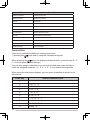
CHARACTER ENTRY
There are 2 methods available for entering characters:
1) pressing the / keys and 2) using the microphone keypad.
When pressing the / keys, the displayed character entry cycles through A ~ Z,
0 ~ 9 and a space (default settings).
You can also assign a character to an optional key and later press that key to
recall the assigned character: A ~ Z, a ~ z, 0 ~ 9, or a space and characters.
When using the microphone keypad, you can enter characters as shown in the
table below:
DTMF Key
14
Default Character Cycle
1
1
2
A
>
B
>
C
3
D
>
E
>
F
4
G
>
H
>
I
5
J
6
M
>
N
>
O
>
6
7
P
>
Q
>
R
>
S
8
T
>
U
>
V
>
8
9
W
>
Y
>
Z
0
[space]
K
>
>
3
>
4
>
L >5
>
X
2
>
>
0
>
7
>
9
SCAN
Scan is useful for monitoring signals on the transceiver channels. While
scanning, the transceiver checks for a signal on each channel and only stops on a
channel if a signal is present.
To begin scanning, press the key programmed as Scan.
• The icon appears on the display.
• The channels included in the scan list are scanned.
• When a signal is detected on a channel, Scan pauses on that channel. The transceiver
will remain on the busy channel until the signal is no longer present. When the signal
“drops out”, the transceiver will remain on the channel momentarily before Scan
resumes. This delay time is programmed by your dealer. If a signal is received during
the delay time, the transceiver will remain on the same channel.
To stop scanning, press the Scan key again.
Note: In order for Scan to operate, there must be at least 2 channels added to the scanning
sequence. If there are less channels than this, Scan will not operate.
TEMPORARY CHANNEL LOCKOUT
If a key is programmed with the Scan Delete/Add function, each channel can be
locked out of the scan sequence manually.
During scan, you can temporarily remove specific channels from the scanning
sequence by selecting them and pressing the Scan Delete/Add key.
• The
icon (right side) no longer appears on the display for that channel.
• The channel is no longer scanned. However, when scanning is ended and restarted, the
channels will reset and the channel will again be in the scanning sequence.
PRIORITY SCAN
A Priority channel must be programmed in order for Priority Scan to function.
When using a single Priority channel, the transceiver will automatically change to
the Priority channel when a call is received on it, even if a call is being received
on a normal channel.
When using dual Priority channels, Priority channel 1 is given precedence over
Priority channel 2. So, if a call is received on Priority channel 1 while a call is
already on Priority channel 2, the transceiver will automatically change to Priority
channel 1.
• “ ” appears on the display when the channel is Priority channel 1, “ ” appears when
the channel is Priority channel 2, and “ ” appears when the channel is both Priority
channel 1 and 2.
15
SCAN REVERT
The Scan Revert channel is the channel selected when you press the microphone
PTT switch to transmit during scan. Your dealer can program one of the following
Scan Revert channels:
•
Last Called + Selected: The last channel on which you received a call is
assigned as the new revert channel. If the channel has been changed, the
newly selected channel is assigned as the new revert channel.
•
Selected: The last channel selected is assigned as the new revert channel.
•
Selected + Talkback: If the channel has been changed, the newly selected
channel is assigned as the new revert channel. The transceiver “talks back”
on the current channel.
•
Priority 1/ Priority 2: If your dealer has programmed a Priority channel
(either Priority 1 or Priority 2), this channel is the revert zone and channel.
•
Priority 1 + Talkback/ Priority2 + Talkback: If your dealer has programmed
a Priority channel (either Priority 1 or Priority 2), this channel is the revert zone
and channel. The transceiver “talks back” on the current receive channel.
SCAN DELETE/ADD
You can add and remove zones and/or channels/group IDs to and from your scan
list.
1 Select your desired zone and/or channel/group ID.
2 Press the key programmed as Zone Delete/Add (to add/remove zones) or
Scan Delete/Add (to add/remove channels/group IDs).
• You can also press and hold the key programmed as Scan Delete/Add to add/
remove zones.
PRIORITY-CHANNEL SELECT
If the Priority channel has been set as Operator Selectable by your dealer, you
are also able to reprogram the Priority mode.
1 Select your desired zone and channel.
2 Press the key programmed as Priority-chanel Select, or press and hold the
key programmed as Scan.
• A list of channel types appears on the display.
3 Press the
/
keys to select the channel type for your current channel.
• You can set the channel as “NORMAL”, “PRIORITY 1”, “PRIORITY 2”, or
“PRIORITY 1&2”.
4 Press the
16
key to save the setting and exit Priority-channel Select Mode.
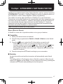
FleetSync: ALPHANUMERIC 2-WAY PAGING FUNCTION
FleetSync is an Alphanumeric 2-way Paging Function, and is a protocol owned by
JVC KENWOOD Corporation. FleetSync enables a variety of paging functions on
your transceiver, some of which depend on dealer programming.
Your dealer can set up either FleetSync or FleetSync II on your transceiver.
Transceivers set up with FleetSync can communicate with other transceivers that
have been set up with FleetSync. Likewise, transceivers set up with FleetSync II
can communicate with other transceivers set up with FleetSync II. However,
transceivers set up with FleetSync cannot communicate with transceivers that
have been set up with FleetSync II, and vice-versa.
Note: This function is available only in analog operation.
SELCALL (SELECTIVE CALLING)
A Selcall is a voice call to a particular station or to a group of stations.
■ Transmitting
1 Select your desired zone and channel.
2 Press the key programmed as Selcall or Selcall + Status to enter Selcall
mode.
3 Press the
/
keys to select the ID of the station you want to call.
• If Manual Dialing is enabled, you can enter the station ID by using the
microphone keypad, or by using the / keys. When using the /
keys,
cycle through the digits to select a digit, then press the
key to set
the digit and move the cursor to the right. Repeat this process until the
entire ID is entered.
4 Press the microphone PTT switch and begin your conversation.
■ Receiving
An alert tone will sound and the transceiver will automatically enter Selcall
Mode.
The calling station’s ID will appear when a Selcall is received. When the call
station’s ID appears on the display, you can respond to the call by pressing the
microphone PTT switch and speaking into the microphone.
17
■ Identification Codes
An ID code is a combination of a 3-digit Fleet number and a 4-digit ID number.
Each transceiver must have its own Fleet and ID number.
•
•
•
•
Enter a Fleet number (100 ~ 349) to make a fleet call.
Enter an ID number (1000 ~ 4999) to make an individual call in your fleet.
Enter a Group ID (which is programmed in the FPU) to make a group call.
Enter a Fleet number followed by an ID number to make an individual call in your
desired fleet (Inter-fleet call).
• Select “ALL” Fleet and “ALL” ID to make a call to all units (Broadcast call).
• Select “ALL” Fleet and enter an ID number to make a call to the selected ID in all
fleets (Supervisor call).
Note:
◆ Broadcast and Supervisor calls are programmed functions that cannot be made with a keypad.
◆ The ID range may be limited by programming.
STATUS MESSAGE
You can send and receive 2-digit Status messages which may be decided in your
talk group. Messages can contain up to 16 alphanumeric characters. Status
messages range from 10 to 99 (80 ~ 99 are reserved for special messages).
A maximum of 15 received messages can be stored in the stack memory of your
transceiver. These saved messages can be reviewed after reception. Depending
on your dealer settings, when the stack memory is full, either the oldest message will
be erased when a new message is received or the new message will not be stored in
the stack memory. The icon lights when a message is stored in the stack memory.
■ Transmitting
1 Select your desired zone and channel.
2 Press the key programmed as Status to enter Status mode or Selcall +
Status to enter Selcall mode.
• When using the Status key to enter Status mode, the target Fleet/ ID is fixed and
cannot be selected. Skip to step 5 to continue.
3 In Selcall mode, press the
want to call.
/
keys to select the ID of the station you
• If Manual Dialing is enabled, you can enter the station ID by using the
microphone keypad, or by using the / keys. When using the /
keys,
cycle through the digits to select a digit, then press the
key to set
the digit and move the cursor to the right. Repeat this process until the
entire ID is entered.
4 Press the
5 Press the
key enter Status mode.
/
keys to select the status ID you want to transmit.
• If Manual Dialing is enabled, you can enter the station ID by using the microphone
keypad, or by using the / keys. When using the / keys, cycle through
the digits to select a digit, then press the
key to set the digit and move
the cursor to the right. Repeat this process until the entire ID is entered.
18
6 Press the microphone PTT switch or the
key to initiate the Status call.
• “<<COMPLETE>>” is displayed when the call has been successfully transmitted.
■ Receiving
The icon will flash and a calling ID or text message will appear when a
Status call is received.
Press any key to return to normal operation.
■ Reviewing Messages in the Stack Memory
1 Press the key programmed as Stack, or press and hold the key
programmed as Selcall, Status, or Selcall + Status to enter Stack mode.
• The last received message is displayed with the message number.
2 Press the
/
keys to select the desired message.
• Message types are identified as follows:
I: Caller ID
S: Status Message
M: Short Message
• You can change the displayed information by pressing and holding the
key
for 1 second. The display cycles as follows:
ID Name > Status/Short Message > CH/GID > Time Stamp > ID Name ...
3 Press the
key to return to normal operation.
• To delete the selected message, press the
key or microphone # key. To
confirm the deletion, press the
key or microphone key.
• To delete all messages, press and hold the
key or microphone # key for 1
second. To confirm the deletion, press the
key or microphone key.
SHORT MESSAGES
To send a short message, you must connect the transceiver to a PC. Ask your
dealer for details.
• Short messages can contain a maximum of 48 characters.
• Received short messages are displayed the same as Status messages and are
stored in the same stack memory. A combined maximum of 15 Status calls and short
messages can be stored in the stack memory.
LONG MESSAGES
To send and receive long messages, you must connect the transceiver to a PC.
Ask your dealer for details.
• Long messages can contain a maximum of 4096 characters.
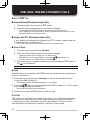
GPS REPORT
To send your location data, you must first connect a GPS unit to the transceiver.
GPS data can be manually transmitted by pressing the key programmed as Send
the GPS data, or by accessing the Send the GPS data function through the Menu
{page 12}. If set up by your dealer, GPS data may be automatically transmitted at a
preset time interval.
19
DTMF (DUAL TONE MULTI FREQUENCY) CALLS
MAKING A DTMF CALL
■ Manual Dialing (Microphone Keypad Only)
1 Press and hold the microphone PTT switch.
2 Enter the desired digits using the microphone keypad.
• The corresponding DTMF tones sound each time you press a key.
• If you release the microphone PTT switch, transmit mode will end even if the
complete number has not been sent.
■ Keypad Auto PTT (Microphone Keypad Only)
If your dealer has activated the Keypad Auto PTT function, simply press the
microphone keys to make the call.
• The DTMF code will be sent automatically when you press a key.
■ Store & Send
1 Press the key programmed as Autodial.
2 Enter the desired digits using the microphone keypad.
• The digits appear on the display as you enter them.
• Alternatively, you can enter digits by using the / keys {page 14}.
• You can enter up to 30 digits before transmitting.
3 After entering the complete number, press the microphone PTT switch or
the
key to transmit.
Note: If you switch the power OFF before transmitting the number, the number will be cleared.
AUTODIAL
Autodial allows you to quickly call DTMF numbers that have been programmed
onto your transceiver.
1 Press the key programmed as Autodial, or access the Autodial function
through the Menu {page 12}.
• The first entry in the Autodial list appears on the display.
2 Press the / keys or enter the appropriate DTMF number (01 ~ 32) to select
your desired Autodial list number.
• The stored entry appears on the display.
3 Press the microphone PTT switch to make the call.
STUN CODE
This function is used when a transceiver is stolen or lost. When the transceiver
receives a call containing a stun code, either transmit mode will be disabled,
or both receive mode and transmit mode will be disabled. The stun code is
cancelled when the transceiver receives a call with a revive code.
20
TRUNKING CALLS
MAKING A TELEPHONE CALL
■ Manual Dialing (Analog)
1 Select your desired zone and telephone group ID.
2 Press the microphone PTT switch to start the call.
3 Enter your desired number using the microphone keys.
■ Selecting a Number from the List
1 Select your desired zone and telephone group ID.
2 Press the key programmed as Autodial.
• The last called unit appears on the display.
3 Press the
/
keys to select your desired list number.
4 Press the microphone PTT switch to start the call.
RECEIVING A TELEPHONE CALL
When a call is received, press and hold the microphone PTT switch to speak, and
release it to receive.
• Only one person can speak at a time.
21
EMERGENCY CALLS
If your transceiver has been programmed with the Emergency function, you can
make emergency calls.
Note: Only the
key and an optional auxiliary switch, such as an emergency foot switch, can be
programmed with the Emergency function.
1 Press and hold the key programmed as Emergency.
• Depending on the delay time programmed into your transceiver, the length of time it
takes to switch to Emergency mode will vary.
• When the transceiver enters Emergency mode, the transceiver will change to the
Emergency channel and begin transmitting based on how the transceiver is set up
by your dealer. Transmit periods are also set by your dealer.
2 To exit Emergency mode, press and hold the Emergency key again.
• If the Emergency mode completes a preset number of cycles, Emergency mode will
automatically end and the transceiver will return to the zone and channel that was in
use before Emergency mode was entered.
Note:
◆ Your dealer can set the transceiver to emit a tone when transmitting in Emergency mode.
◆ Your dealer can set the transceiver to emit tones and received signals as normal or mute the
speaker during Emergency operation.
22
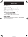
SCRAMBLER
Note: Ask your dealer for details concerning the Voice Scrambler board.
SECURE (ENCRYPTED) TRANSMISSION
Press the key programmed as Scrambler/ Encryption, or access the Scrambler
function through the Menu {page 12}, to switch the transceiver to secure
(encrypted) transmission.
• The icon appears when the Scrambler function is turned ON.
• Pressing the microphone PTT switch after the Scrambler function has been turned ON
encrypts the transmitted signal.
23
SIGNALING
QUIET TALK (QT)/ DIGITAL QUIET TALK (DQT)
Your dealer may have programmed QT or DQT signaling on your transceiver
channels. A QT tone/ DQT code is a sub-audible tone/code which allows you to
ignore (not hear) calls from other parties who are using the same channel.
When a channel is set up with a QT tone or DQT code, squelch will only open
when a call containing a matching tone or code is received. Likewise, signals that
you transmit will only be heard by parties whose QT/ DQT signaling matches your
transceiver.
If a call containing a different tone or code is made on the same channel you
are using, squelch will not open and you will not hear the call. This allows you
to ignore (not hear) these calls. Although it may seem like you have your own
private channel while using QT/ DQT, other parties can still hear your calls if they
set up their transceiver with the same tone or code.
■ Operator Selectable Tone (OST)
If a key has been programmed with OST, you can reprogram the QT/DQT
settings on each of your channels.
1 Select your desired channel.
2 Press and hold the key programmed as OST for 1 second.
• The
icon appears on the display.
3 Press the / keys to select your desired tone or code. (Your dealer can
set up to 40 tones/codes.)
4 Press the
key to save your new setting.
After selecting and setting up your desired tone or code, the OST function is
activated. When you have finished operating using OST, press the OST key to
turn the OST function OFF.
24
RADIO ACCESS NUMBER (RAN)
RAN is a new signaling system designed only for digital radio communications.
The operation is the same as the analog QT/ DQT signaling.
When a channel is set up with a RAN, squelch will only open when a call containing
a matching RAN is received. Likewise, signals that you transmit will only be heard
by parties whose RAN signaling matches your transceiver.
If a call containing a different RAN is made on the same channel you are using,
squelch will not open and you will not hear the call. This allows you to ignore (not
hear) these calls.
OPTIONAL SIGNALING
Your dealer may also program several types of option signaling for your
transceiver channels.
DTMF Signaling: DTMF Signaling opens the squelch only when the transceiver
receives a call containing a matching DTMF code. Refer to “DTMF (DUAL TONE
MULTI FREQUENCY) CALLS” on page 20.
FleetSync Signaling: Refer to “SELCALL (SELECTIVE CALLING)” on page 17.
NXDN ID Signaling: NXDN ID is an optional signaling system available only for
digital communications.
25
ADVANCED OPERATIONS
CLOCK
If activated by your dealer, your transceiver can track the time with its builtin clock. The time will display momentarily when the transceiver power is
turned ON. Additionally, you can view the clock any time by pressing the key
programmed as Clock.
Note: Removing the transceiver power for extended periods will cause the clock time to clear.
■ Clock Adjustment
To set the time:
1 Press the key programmed as Clock Adjustment.
• The current time setting appears.
2 Press the
3 Press the
/
keys to increase or decrease the year setting.
key to set the year and cycle to the month setting.
4 Repeat steps 2 and 3 to set the day, hour, and minute.
5 Press the
key to exit Clock Adjustment mode.
• You can press
at any time to exit Clock Adjustment mode.
LCD BRIGHTNESS
The LCD backlight can be turned off or set to low or high levels. To cycle through
the brightness settings, press the key programmed as LCD Brightness.
• Each press of LCD Brightness cycles the brightness level from high to low to off, and
then back to high.
HORN ALERT
To use the Horn Alert function, your dealer must install an optional unit. When
a call is received that matches the optional signaling set up on your transceiver,
Horn Alert causes the vehicle horn or some other external alert to sound. This
function notifies you of a received call when you are away from your vehicle.
To toggle Horn Alert ON and OFF, press they key programmed as Horn Alert or
access the Horn Alert function through the Menu {page 12}.
• HA momentarily appears on the display when Horn Alert is active.
26
PUBLIC ADDRESS (PA)
To use the Public Address system, your dealer must install an optional unit and an
external speaker. This function causes all audio input via the microphone to be
amplified and output through the external speaker.
To use the PA system:
1 Press the key programmed as Public Address or access the Public Address
function through the Menu {page 12}
• PA appears on the display when the PA system is active.
2 Press and hold the microphone PTT switch, then speak into the microphone.
• Use the Volume Up and Volume Down keys to adjust the audio output from the
external speaker.
3 Press the Public Address key again or change the zone or CH/GID to return
to normal operation.
27
BACKGROUND OPERATIONS
Your dealer can activate a variety of transceiver functions to perform without any
additional operation on your part.
TIME-OUT TIMER (TOT)
The Time-out Timer is used to prevent any caller from using a channel for an
extended period of time.
If you continuously transmit for a period of time that exceeds the programmed
time, the transceiver will stop transmitting and an alert tone will sound. To stop
the tone, release the microphone PTT switch.
If programmed by your dealer, a pre-alert tone will sound before the timer expires.
Also, if programmed by your dealer, you may have to wait for a short duration
before you can continue to transmit. If you press the microphone PTT switch
before the timer has been reset, an alert tone will sound and the transceiver will
not enter transmit mode.
SIGNAL STRENGTH INDICATOR
The signal strength indicator displays the strength of received calls.
Strong signal
Sufficient signal
Weak signal
Very weak signal
No icon appears when no signal is available
Flashes when out of range (NXDN Trunking only)
COMPANDER
The compander can be programmed only for specific FM channels. If it has been
programmed by your dealer, transmitted signals are compressed before being
sent and received signals are expanded when they arrive.
• Your dealer must set the compander for both the transmit side and the receive side in
order for the compander to operate.
This background feature allows higher clarity of signals, avoiding excessive noise.
This feature is not used on digital channels, as they are not susceptible to noise
and interference.
28
BUSY CHANNEL LOCKOUT (BCL)
On Conventional channels, if BCL is set up by your dealer, you will be unable to
transmit on the channel if it is already in use. Under these circumstances, use a
different channel or wait until the channel becomes free.
However, if BCL Override has also been programmed, you can transmit over the
current signal:
1 Press and hold the microphone PTT switch.
• If the channel is already in use, a warning tone will sound.
2 Release the PTT switch, then press and hold the microphone PTT switch
again within half a second.
3 Speak into the transceiver as you would during a normal call.
CONTROL CHANNEL HUNT
On digital Trunking channels, the transceiver must search for a control channel.
While searching for a control channel, no signals can be received. The search
begins automatically when you change to a digital Trunking channel.
• While hunting for a control channel, the antenna icon will flash. When an available
system has been found, the antenna icon remains on the display without flashing.
PTT ID
PTT ID is the transceiver unique ID code which is sent each time the microphone
PTT switch is pressed.
Note: PTT ID can be made only in analog operation.
If Beginning of Transmit is set, the ID signal is transmitted when you press the
microphone PTT switch.
If End of Transmit is set, the ID signal is transmitted when you release the
microphone PTT switch.
If both are set, the ID signal is transmitted when you press and release the
microphone PTT switch.
29
VGS-1 OPTIONAL VOICE GUIDE & STORAGE UNIT
When using the optional VGS-1 voice guide & storage unit, you gain access to the
voice recorder and voice announcement functions. Ask your dealer for details.
VOICE RECORDER
The voice recorder provides you with an auto recorder to record your
conversations and a voice memo function to create voice memos.
■ Auto Recording
If activated, the auto recording function will continuously record all transmitted
and received signals. The recording storage area retains 30 seconds of
recording, so all transmitted and received signals are simultaneously recorded
and erased, leaving only the last 30 seconds of recording in memory.
• The
icon appears on the display when this function is activated.
■ Voice Memos
To record a voice memo, for later playback:
1 Press the key programmed as Voice Memo, press and hold the key
programmed as Playback for 1 second, or access the Voice Memo function
through the Menu {page 12}.
• The duration of recording memory will appear on the display and begin counting
down.
2 Speak into the microphone to record your voice memo.
3 Press the
key to end the recording at any time and store it into the
transceiver memory.
• If the memory becomes full, recording will stop automatically and store the voice
memo to memory.
30
■ Auto Reply Message
You can set the transceiver to automatically respond to Individual Calls (while
using FleetSync/NXDN):
1 Press the key programmed as Auto Reply Message to enter Auto Reply
Message mode.
• The
icon appears on the display.
2 When you receive an Individual Call, Auto Reply will begin after waiting for
3 seconds, the transceiver will send an automatic response to the caller,
and “GREETING” appears on the display
• If you are available to receive the call, press any key to cancel the auto
response.
• If there is a channel available on your transceiver for recording, “I am not
available. Leave your Message.” will be sent to the caller. The caller can then
leave a recorded message on your transceiver which you can later recall and
listen to. When a message is stored on your transceiver, “Msg Rcvd” appears on
the display.
• If there is no channel available on your transceiver for recording, “I am not
available” will be sent to the caller and “ MEMORY FULL” appears on the display.
■ Playback
To play back a recorded conversation, memo, or message:
1 Press the key programmed as Playback or access the Playback function
through the Menu {page 12}.
• If the last action on your transceiver was to auto record your conversation,
“STORE?” will appear on the display, otherwise a recording channel with the time
of the recording will appear.
2 Press the
/
keys to select the channel you want to play back.
• “AR” represents auto recorded conversations.
• “RM” represents auto reply messages.
• “VM” represents voice memos.
3 The transceiver will announce the time and channel, then the recording will
automatically play back.
• When the entire recording has been played, “END OF MESSAGE” is displayed.
You can also end the recording at any time by pressing the
key.
• To delete the selected recording, press the
key. To clear all the recorded
data, press and hold the
key.
VOICE GUIDE
If set up by your dealer, when changing the zone and/or channel, an audio voice
will announce the new zone and channel number/group ID. Additionally, when
changing a function setting, an audio voice will announce the new setting. (Voice
announcements vary by dealer setting.)
31